

Teaberry НР - 141 T Service Manual


TECHNICAL MANUAL
OPERATOR’S ORGANIZATIONAL, DIRECT SUPPORT, AND
GENERAL SUPPORT MAINTENANCE MANUAL
INCLUDING REPAIR PARTS AND SPECIAL TOOLS LISTS
FOR
SPECTRUM ANALYZER IP-1 21 6(P)/GR
(HEWLETT-PACKARD MODEL 141T)
(NSN 6625-00 424 4370)
This copy is a reprint which Includes current
pages from Change 1.
HEADQUARTERS, DEPARTMENT OF THE ARMY
TM 11-6625-2781-14&P
JUNE 1977

WARNNG NOTICE
A SHOCK HAZARD MAY EXIST ON THE FAN HOUSING OR ANY METAL PART COMMON TO IT . IF ANY OF THE
SERIES REGULATORS, THE TERMINAL SWITCH, OR THE FAN MOTOR ITSELF SHOULD SHORT T O TIHE FAN
HOUSING, A SHOCK HAZARD WOULD EXIST. TO ELIMINATE THE POTENTIAL SHOCK HAZARD, IT IS
NECESSARY TO INSTALL A GROUND WIRE FROM THE FAN HO USING TO T HE CHASSIS OF THE INST RUMENT;
PROCEED AS FOLLOWS:
a. Solder one end of ground wire to the chassis side of R11, as shown at point A of the figure below.
b. Install a starred washer and a ground lug ’under existing hardware, as shown at point B.
c. Solder other end of ground wire to ground lug.
AFTER INSTALLATION OF THE GROUND WIRE, INSURE THE FAN ASSEMBY HAS GOOD CONTINUITY TO
GROUND.
Parts required /one each)
Wire, black, 18 awg, 8 inches
Solder lug
External starred washer

TM 11-6625-2781-14&P
CHANGE
HEADQUARTERS
DEPARTMENT OF THE ARIMY
NO. 1 WASHINGTON, DC, 11
Operator’s, Organizational, Direct Support, And
General Support Maintenance Manual
(Including Repair Parts And Special Tools Lists)
For
SPECTRUM ANALYZER IP- 1216(P)/GR
(HEWLETT-PACKARD MODEL 141T)
(NSN 6625-00-424-4370)
TM 11-6625-2781-14&P, 1 June 1977, is changed as follows:
1. New or changed material is indicated by a vertical bar in the margin of the page.
2. Remove and insert pages as indicated below:
Remove Insert
i through 0-2..................i through 0-2
6-1 through 6-18............None
B-1.................................B- through B-28
C-l through C-5..............C- through C-4
3. File this change sheet in front of the publication for reference purposes.
C1
August 1978,
By Order of the Secretary of the Army:
Official:
J. C. PENNINGTON
Brigadier General, United States Arm
y
The Adjutant General
DISTRI BUTION:
Active Army:
TSG (1) Army Dep (1) except
USAARENBD (1) Fort Carson (5)
USAINSCOM (2) Fort Gillem (10)
TRADOC (2) Fort Huachuca (5)
DARCOM (1) Ft Richardson (CERCOM Ofc) (1)
TECOM (2) LBAD (10)
OS Maj Comd (2) SAAD (30)
USACC (2) TOAD (14)
HISA (Ft Monmouth)(33) SHAD (3)
Armies (I) Sig See USA Dep (1)
USASIGS (10) Units org under fol TOE’
Svc Colleges (1) 29-134 (1)
WSMR (1) 29-136 (1)
USAERDAA (1) 29-207 (2)
USAERDAW (1) 29-610 (2)
USA Dep (1)
NG.
None
USAR
For explanation of abbreviations used see, AR 310-50
None
BERNARD W. ROGERS
General, United States Army
Chief of Staff

TM 11-6625-2781-14&P
This manual contains copyright material reproduced by permission of the Hewlett-Packard Company.
TECHNICAL MANUAL, HEADQTUARTERS
DEPARTMIENT OF THE AR MY
} WASHINGTON ,
NO 11-6625-2781-14&P
OPERATOR’S, ORGANIZATIONAL, DIRECT SUPPORT, AND
GENERAL SUPPORT MAINTENANCE MANUAL
(INCLUDING REPAIR PARTS AND SPECIAL TOOLS LISTS)
FOR
SPECTRUM ANALYZER IP- 1216(P)/GR
(HEWLETT-PACKARD MODEL 141T)
(NSN 6625-00-424-4370)
REPORTING OF ERRORS
You can improve this manual by recommending improvements using DA Form 2028-2 (Test)
located in the back of the m anual. Simply tear out the self-addressed form , fill it out as shown on the
sample, fold it where shown, and drop it in the mail.
If there are no blank DA Forms 2028-2 (T est) in the back of your manual, use the standard DA
Form 2028 (Recomm ended Changes to Publications and Blank Forms) and forward to the Com mander,
US Army Communications and Electronics Materiel Readiness Command, ATTN: DRSEL-MA-Q, Fort
Monmouth, New Jersey 07703.
1JUNE 1977
In either case a reply will be furnished direct to you.
Change 1 i

TM 11-6625-2781-14&P
SAFETY SUMMARY
The following general safety precautions must be observed during all phases of operation, service, and repair of this
instrument. Failure to comply with these precautions or with specific warnings els ewhere in his manual violates safety
standards of design, manufacture, and intended use of the instrument. Hewlett-Pac kard Company assumes no liability for
the customer’s failure to comply with these requirements.
GROUND THE INSTRUMENT.
To minimize shock hazard, the instrument chassis and cabinet must be connected to an electrical gr ound. The instrument
is equipped with a three-conductor ac power cable. The power cable must either be plugged into an approved threecontact electrical outlet or used with a three-contact to two-contact adapter with the grounding wire (green) firmly
connected to an electrical ground (safety ground) at the power outlet. The power jack and mating plug of the power cable
meet International Electrotechnical Commissioned (IEC) safety standards.
DO NOT OPERATE IN AN EXPLOSIVE ATMOSPHERE.
Do not operate the instrument in the presence of flammable gases or fumes. Operation of any electric al instrument in
such an environment constitutes a definite safety hazard.
KEEP AWAY FROM LIVE CIRCUITS.
Operating personnel must not remove instrument covers. Component replacement and internal adjustments must be
made by qualified maintenance personnel. Do not replace components with power cable connected. Under certain
conditions, dangerous voltages may exis t even with the power c able removed. To av oid injuries always dis connect power
and discharge circuits before touching them.
DO NOT SERVICE OR ADJUST ALONE.
Do not attempt internal service or adjustment unless another person, cable of rendering first aid and resuscitation, is
present.
USE CAUTION WHEN EXPOSING OR HANDLING THE CRT.
Breakage of the cathode-ray tube (CRT) causes a high velocity scattering of glass fr agments ( implosion) . To pr event CRT
implosion, avoid rough handling or jarring of the instrument. Handling of the CRT shall be done only by qualified
maintenance personnel using approved safety mask and gloves.
DO NOT SUBSTITUTE PARTS OR MODIFY INSTRUMENT.
Because of the danger of introducing additional hazards, do not install substitute parts or perform any unauthorized
modification to the instrument. Return the instrument to a Hewlett-Packard Sales and Service Officer for service and
repair to ensure that safety features are maintained.
DANGEROUS PROCEDURE WARNINGS.
Warnings, such as the example below, precede potentially dangerous procedures throughout this manual. Instructions
contained in the warnings must be followed.
Dangerous voltages, capable of causing death, are present in this instrum ent. Use ex trem e caution when
handling, testing, and adjusting.
Change 1 ii

Model 141T
TM 11-6625-2781-14&P
TABLE OF CONTENTS
Section Title Page
0 GENERAL..................................................................... 0-1
I GENERAL INFORMATION........................................... 1-1
1-1 Introduction.........................................................1-1
1-4 Description..........................................................1-1
1-9 Cathode Ray Tube..............................................1-1
1-11Warranty.............................................................1-1
1-13Associated Equipment........................................1-1
1-15Instrument and Manual Identification..................1-3
1-19Inquiries.................................................................1 - 1-3
II INSTALLATION.................................................. 2-1
2-1 Introduction........................................................ 2-1
2-3 Initial Inspection................................................. 2-1
2-6 Preparation for Use............................................ 2-1
2-9 Three-conductor Ac Power Cable..................... 2-2
2-11Instrument Mounting.......................................... 2-2
2-14Instrument Cooling............................................. 2-3
2-17Claims......................................................... 2-3/’2-4
2-19Repacking for Shipment.............................. 2-3/2-4
III OPERATION...................................................... 3-1
3-1 Introduction........................................................ 3-1
3-3 Controls and Connectors................................... 3-1
3-5 Trace Align......................................................... 3-1
3-7 Beam Finder...................................................... 3-1
3-9 Focus and Astigmatism..................................... 3-1
3-11Z-axis Input........................................................ 3-1
3-13Plug-in Units...................................................... 3-1
3-19Operating Considerations.................................. 3-4
3-20Definitions.......................................................... 3-4
3-22Control Functions............................................... 3-4
3-30Operating Procedures........................................ 3-5
3-32Single-shot Operation........................................ 3-6
SectionTitle Page
V PERFORMANCE CHECK AND AD-
JUSTMENTS.................................................................5-1
5-1 Introduction...................................................... 5-1
5-3 Test Equipment.................................................5-1
5-5 Performance Check......................................... 5-1
5-8 Preliminary Setup............................................ 5-1
5-9 Beam Finder.....................................................5-2
5-11 Focus and Astig............................................... 5-2
5-13 Trace Align.................................................... 5-5-2
5-14 Calibrator......................................................... 5-2
5-15 Variable Persistence.........................................5-2
5-16 Writing Speed, Fast..........................................5-2
5-17 Store Time, Fast.............................................. 5-3
5-18 Writing Speed, Standard....................................53
5-19 Store Time, Standard....................................... 5-3
5-21 Adjustments.................................................... 5-3
5-24 Preliminary Setup........................................... 5-3
5-25 Low Voltage Power Supply
Adjustment....................................................... 5-3
5-26 High Voltage Power Supply
Adjustment....................................................... 5-3
5-27 Intensity Limit Adjust........................................ 5-4
5-28 -Geometry--..................................................... 5-5
5-29 Calibrator Adjustment...................................... 5-5
5-30 Pulse Circuit Adjustments................................ 5-5
VI REPILACEABILE PARTS DELETED
VII MANUAL CHANGES AND OPTIONS.............. 7-1
7-1 Introduction.......................................................7-1
7-3 Manual Changes...............................................7-1
7-5 Special Options.................................................7-4
7-9 Standard Options..............................................7-4
7-14. Additional Manual Changes................................7-4
IV PRINCIPI,ES OF OPERATION.......................... 4-1
4-1 Introduction........................................................ 4-1
4-3 Overall Functional Description........................... 4-1
4-5 Low-voltage Power Supply................................. 4-1
4-7 Calibrator.......................................................... 4-1
4-9 High-voltage Power Supply................................ 4-1
4-11Pulse Circuit....................................................... 4-2
4-13Horizontal Driver Circuit..................................... 4-2
4-15Circuit Description.............................................. 4-2
4-16Low-voltage Power Supply................................. 4-2
4-24Calibrator........................................................... 4-3
4-28High-voltage Supply........................................... 4-3
4-34Storage CRT...................................................... 4-4
4-41lPulse Circuit....................................................... 4-4
4-41 STD and Fast Modes......................................... 4-4
1-5,3 Pulse Circuit’ Store Mode............................... 4-6
4-57 Pulse Circuit: Conventional Mode.................. 4-6
4-60 Trace Align............................................... 4-7/4-8
4-62 Plug-in Kit Fabrication.............................. 4-7/4-8
Change 1 iii
VIII SCHEMATICS AND TROUBLE-
SHOOTING...................................................... 8-1
8-1 Introduction.......................................................8-1
8-3 Schematics.......................................................8-1
8-8 Reference Designations...................................8-1
8-12 Component Locations...................................... 8-1
8-14 Preventive Maintenance.................................. 8-1
8-15 DELETED.
8-17 Filter Maintenance............................................8-2
8-19 Electrical Maintenance......................................8-2
8-21 Repair and Replacement................................. 8-2
8-23 Instrument Repair.............................................8-2
8-26 CRT Removal and Replacement......................8-2
8-29 Fan Removal and Replacement...................... 8-2
8-31 Semiconductor Replacement........................... 8-2

List of Illustrations
TM 11-6625-2781-14&P
TABLE OF CONTENTS
Section Title Page
8-33.Servicing Circuit Boards..................................... 8-3
8-36. Overall Troubleshooting..................................... 8-3
8-39.Front Panel Controls.......................................... 8-4
8-41.Visual Checks.................................................... 8-4
8-43.Waveforms and Voltages..................................... 8-4
8-45.Final Checks...................................................... 8-4
8-47Detailed Troubleshooting................................... 8-4
8-48.Low-Voltage Supply........................................... 8-4
8-55.High-Voltage Supply.......................................... 8-6
8-60Pulse Circuit....................................................... 8-6
APPENDIX A References............................................. A-1
APPENDIX B Organizational, Direct Sup-
port, and General Support
’Maintenance Repair Parts
and Special Tools List (Including Depot Maintenance
Repair Parts and Special
Tools)
I INTRODUCTION.......................................................... B-1
II REPAIR PARTS LIST................................................... B-9
LIST OF ILLUSTRATIONS
Figure Title Page
1-1 Model 141T Display Section.............................. 1-0
1-2 Instrument Serial Number -................................ 1-3
2-1 Voltage Selection............................................... 2-1
2-2 Rear Mounting Procedure.................................. 2-2
3-1. Mode(141T Controls and Connectors................ 3-2
3-2 Intensity Adjustment.......................................... 3-3
3-3 Background Illumination immediately
after- erasing with ’RITING SPEED
in FAST and PERSISTENCE to
MAX S................................................................ 3-5
3-4 Persistence with a Slow Repetitive
Sweep............................................................... 3-5
3-5 Single-shot Trace Bloom caused by
INTENSITY and/or PERSISTENCE
set too high........................................................ 3-5
.3-6.Single-shot Display With INTENSITY
and PERSISTENCE set the same as
figure 3-5 and Increased Amplitude................... 3-5
3-7. Fade Positive after 2 to 4 minutes
in STD mode...................................................... 3-6
3-8 Single-shot 20 usec/div display......................... 3-6
3-9 Same Display as figure :3-S after
three minutes in STD mode............................... 3-6
Model 1llT
Section Title Page
Group OOSpectrum Analyzer IP-1216(P)/
GR (Hewlett-Packard Model
141T)....................................................... B-9
01 Circuit Card Assembly, Al..................... B-13
02 Circuit Card Assembly, Power
Supply, A2............................................. B-17
03 Circuit Card Assembly, Pulse, A.5........ B-21
04 Circuit Card Assembly, Horizon
tal Drive, A6.......................................... B-25
III SPECIAL TOOLS LIST (Not applicable)
IV NATIONAL STOCK NUMNBER AND
PART NUMBER INDEX........................ B-26
APPENDIX C Maintenance Allocation
I INTRODTUCTION.................................. C-1
II MAINTENANCE ALLOCATION
CHART.................................................... C-3
III TOOL AND TEST EQIUIPMENT
REQUIREMENTS................................... C-4
IV REMARKS (Not applicable)
Figure Title Page
3-10.Small Bright Spots caused by Minute
Imperfections in Storage Mesh.......................... 3-6
4-1. Model 141T Block Diagram ---........................... 4-1
4-2. Regulated Power Supply- Block
Diagram-............................................................ 4-2
4-3. High-voltage Power Supply Block
Diagram............................................................. 4-3
4-4. Pulse Circuit Block Diagram.............................. 4-5
4-5. Erase Functional Waveform.............................. 4-6
5-1ASpectrum Analyzer Intensity Limit
adjust-................................................................ 5-4
5-1. Adjustment Location...................................... 5-7/5-8
6-1
thru
6-5DELETED...........................................................................I
7-1A.Effect of Change 11........................................... 7-3
7-1. Component Identification Pulse
Circuit A5........................................................... 7-5
7-2 Pulse Circuit Schematic..................................... 7-5
7-3 Line Voltage Schematic..................................... 7-6
7-4. Option 009 Schematic Diagram......................... 7-6
7-5. Pulse Circuit Schematic..................................... 7-7
7-6 Line Voltage Schematic..................................... 7-8
Change 1 iv

Model 141T
TM 11-6625-2781-14&P
LIST OF ILLUUSTRATIONS
Figure Title Page
8-1 Semiconductor Terminal Identi-
fication............................................................ 8-3
8-2 Component Location, Top View..................... 8-8
8-3 Component Location, Bottom View................ 8-9
8-4 Component Location, Front View................. 8-10
8-5 Component Location, Rear View -............... 8-12
8-6 Plug-in Jack Connections............................. 8-13
8-7 Auxiliary A and Auxiliary B Wiring
Diagram........................................................ 8-13
8-8 Component Identification, Power
Supply A2..................................................... 8-14
8-9. Component Identification, Diode
Assy A1........................................................ 8-15
8-10. Low Voltage Schematic................................ 8-15
8-11. Component Identification, Power
Supply A2..................................................... 8-16
8-12. Component Identification, Horizontal
Driver A6...................................................... 8-17
8-13. High Voltage Schematic............................... 8-17
8-14. Component Identification, Pulse
Circuit A5...................................................... 8-18
8-15. Waveforms................................................... 8-19
8-16 Pulse Circuit Schematics............................ 8-19
LIST OF TABLES
Figure Title Page
B-1 Spectrum Analyzer IP-1216(P)/GR
(Hewlett-Packard Model 141T)
(Sheet 1 of 5)................................................. B-4
B-1 Spectrum Analyzer IP-1216(P)/GR
(Hewlett-Packard Model 141T)
(Sheet 2 of 5)................................................. B-4
B-1 Spectrum Analyzer IP-1216(P)/GR
(Hewlett-Packard Model 141T)
(Sheet 3 or 5)................................................. B-6
B-1 Spectrum Analyzer IP-1216(P)/GR
(Hewlett-Packard Model 141T)
(Sheet 3 or 5)................................................. B-6
B-1 Spectrum Analyzer IP-1216(P)/GR
(Hewlett-Packard Model 141T)
(Sheet 5 of 5)................................................. B-8
B-2 Circuit Card Assembly, Diode...................... B-12
B-3 Circuit Card Assembly, Power Supply
(Sheet 1 of 2)............................................... B-15
B-3 Circuit Card Assembly, Power Supply
(Sheet 2 of 2)............................................... B-16
B-4 Circuit Card Assembly, Pulse...................... B-20
B-5 Circuit Card Assembly, Horizontal
Drive............................................................. B-24
Table Title Page
1-1 Specifications..................................................... 1-2
1-2. Reference Designators and Abbre-
viations-............................................................. 1-3
1-3. Plug-ins for Model 141T Display
Section................................................................1-4 -1-
4-1. Current Capability........................................ 4-7/4-8
5-1 Recommended Test Equipment........................ 5-1
Performance Check Record............................. 5-4a
5-2 Low Voltage Power Supply Adjustment............. 5-4
Change 1 v
Table Title Page
6-1
thru
6-4 DELETED
7-1 Manual Changes................................................7-1
7-2 DELETED
7-3 Option 009, Replaceable Parts...........................7-4
8-1 Troubleshooting High-voltage Supply,
No Voltage..........................................................8-5
8-2. Troubleshooting Hligh-voltage Supply,
Incorrect Voltage............................................... 8-5
8-3. Schematic Diagram Notes................................. 8-7
TM 11-6625-2781-14&P
General Information Model 141T
141T-R-14 1
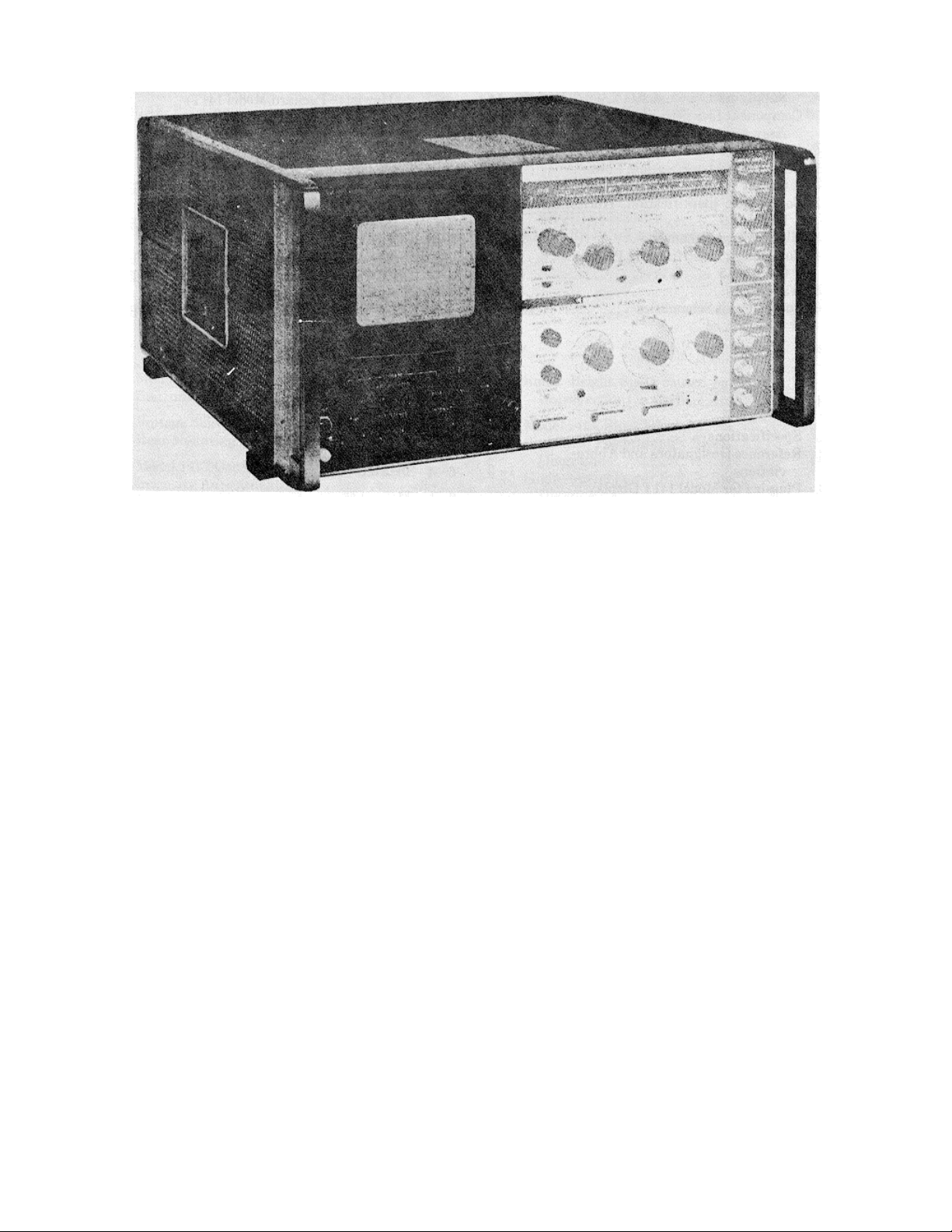
Figure 1-1. Model 141T Display Section
1-0

TM 11-6625-2781-14&P
SECTION 0
GENERAL
0-1. SCOPE.
This manual describes Spectrum Analyzer IP-1216(P)/GR (fig. 1-1) and provides instructions for operation and
maintenance. Through- out this manual, the IP-a216(P)/GR is referred to as the Hewlett-Packard Model lh1T.
0-2. INDEXES OF PUBLICATIONS.
a. DA Pam 310-4. Refer to the latest issue of DA Pam 310-4 to determine whether there are new editions,
changes, or additional publications pertaining to the equipment.
b. DA Pam 310-7. Refer to DA Pam 310-7 to determine whether there are modification work orders (MW O’s)
pertaining to the equipment.
0-3. FORMS AND RECORDS.
a. Reports of Maintenance and Unsatisfac tory Equipment. Maintenance forms, recor ds, and reports which are to
be used by maintenance personnel at all maintenance levels are listed in and prescribed by TM 38-750.
b. Report of Packaging and Handling Deficiencies. Fill out and forward DD Form 6 (Packaging Improvement
Report) as prescribed in AR700-58/NAVSUPINST 4030.29/AFR 71-13/MCO P4030.29A and DSAR 4145.8.
c. Discrepancy in Shipment Report (DISREP) (SF 361). Fill out and forward Discrepancy in Shipment Report
(DISREP) (SF 361) as prescribed in AR 55-38/NAVSUPINST 4610.33A/AFR 75-18/MCO P4610.19B and
DSAR 4500.15.
0-4. REPORTING EQUIPMENT IMPROVEMENT RECOMMENDATIONS (EIR).
EIR’s will be prepared using DA Form 2407, Maintenance Request. Instructions for preparing EIR’s are provided in
TM 38-750, The Army Maintenance Management System. EIR’s should be mailed directly to Commander, US Army
Communications and Electronics Materiel Readiness Command, AT TN: DRSEL-MA,-Q, Fort Monmouth, NJ 07703. A
reply will be furnished directly to you.
Change 1 0-1

TM 11-6625-2781-14&P
0-5. ADMINISTRATIVE STORAGE.
Administrative storage of equipment issued to and used by Army activities shall be in accordance with TM 740-90-1.
0-6. DESTRUCTION OF ARMY ELECTRONICS MATERIEL.
Destruction of Army electronics materiel to prevent enemy use shall be in accordance with TM 750-244-2.
0-2

TM 11-6625-2781-14&P
Model 141T General Information
SECTION I
GENERARAL INFORMATION
1-1. INTRODUCTION.
1-2. This manual provides operating and service
information for the Hewlett-Pack ard Model 141T Display
Section (figure 1-1). The manual is divided into eight
sections, each covering a specific topic or as pect of the
instrument. All schematics are located at the rear of the
manual and can be unfolded and used for reference
while reading any part of the manual.
1-3. This section contains a description of the Model
141T. The instrum ent s pecific ations ar e listed in table 1-
1. Table 1-2 lists and describes the abbreviations used
in this manual except Section VI. The parts list is a
computer printout and uses computer supplied
abbreviations. Table 1-3 contains a list of current plugins available for use with the Model 141T.
1-4. DESCRIPTION.
1-5. The Model 141T is designed for use as a display
section for the HP Model 141T/8550-series plug-in
spectrum analyzer and as an oscilloscope when used
with HP Model 1400-series plug-ins. The instrum ent has
variable persistence (duration of trace afterglow) and
storage of CRT displays. Persistence is variable from
0.2 second to more than 60 seconds . A display can be
stored (at reduced intensity) for more than hours or
displayed at normal intensity for up to 1 minute. Stored
displays can be erased in 350 milliseconds.
20 MHz and sensitivities to 100 microvolts per division
are available as well as time domain reflectometry and
swept frequency indicator units.
1-9. CATHODE RAY TUBE.
1-10. The Model 141T uses a post- ac celer ator CRT with
a non-glare rectangular faceplate. An internal graticule is
located on the same plane as the display to eliminate
parallax errors. The tube has a 9-kV accelerating
potential, and 8 vertical by 10 horizontal divisions. A type
P31 phosphor is used in the standard CRT.
CAUTION
The warranty may be void for
instruments having a mutilated serial
number tag.
1-11. WARRANTY.
1-12. The instrument ( except the CRT) is certified and
warranted as stated on the inside front cover of this
manual. The CRT is covered by a separate warranty.
The CRT warranty and a warranty claim form are located
at the rear of this manual. Should the CRT fail within the
time specified on the CRT warranty page, complete the
warranty claim form and return it with the defective CRT.
The procedure for returning a defective CRT is described
on the CRT warranty page.
1-6. Variable persistence is especially useful for viewing
slow-sweep signals. The persistence of the signals f rom
electrocardiograms or other bio-chemical phenomena
can be adjusted to provide a complete trace, yet to fade
fast enough to prevent interference with the next trac e..
Display persistence of swept frequency and time domain
reflectometry measurem ent readouts can be adj usted to
eliminate flicker and still provide high resolution.
1-7. The storage feature of the instrum ent can be used
to store single-shot waveforms and to later view or
photograph the phenomena. Comparis on of wave form s
can be accomplished by storing several display
separately and then viewing them simultaneously.
1-8. The instrument ac cepts all HP Model 1400 series
plug-in units. Amplifiers with bandwidths to
1-13. ASSOCIATED EQUIPMENT.
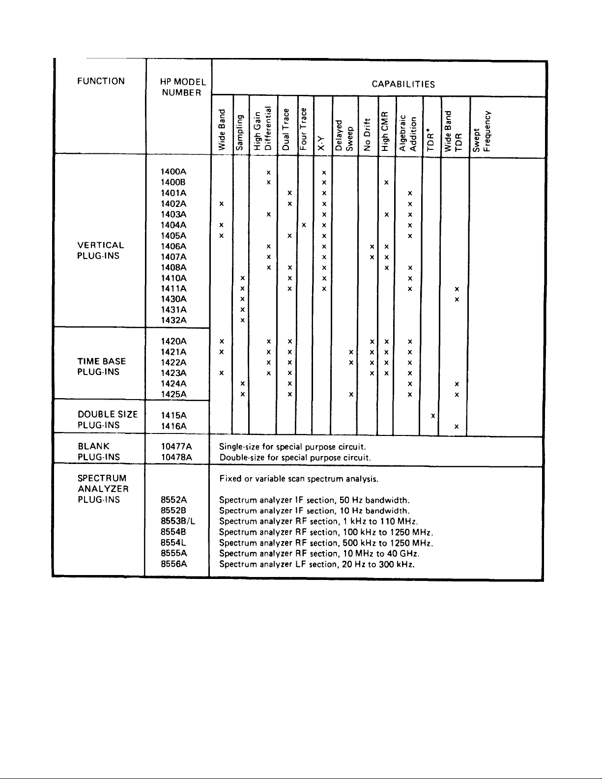
1-14. Plug-ins available for use with the instrument are
listed in table 1-3 and in the Hewlett-Packard
Instrumentation Catalog. The instrument is normally
operated with an IF section plug-in in the lower
compartment and an RF section plug-in in the upper
compartment. T he instrument can also be used as an
oscilloscope with a vertical plug-in in the lower
compartment and a time-base plug-in in the upper
compartment. Both plug-in com partments are the sam e
size, and the plug-in instruments may be interchanged
for any special application. The divider shield that
separates the two compartments can be removed and
one double sized plug-in installed. Blank plug-in kits,
both single and double sized, are available for fabrication
of special circuits. See table 4-1 for power supply
current limitations.
1-1

TM 11-6625-2781-14&P
General Information Model 141T
Table 1-1. Specifications
PLUG-INS
Accepts Model 8050-series IF and RF Section spectr um
analyzer plug-ins without the use of a center divider
shield
Also, accepts all HP Model 1100-series plug-ins. All
plug-ins operate directly into the horizontal and vertical
deflection plates. Centaur shield may be removed to
provide double-sized compartment f or use with a single,
dual axis Model 1400-series unit.
CATHODE-RAY TUBE
Type:
Post-accelerator storage tube; 9000s V accelerating
potential; aluminized P31 phosphor; etched safety glass
face plate.
Graticule:
8 x 10 divisions (approx. 7.1 .: 8.9 cm) parallax-free
internal graticule. Subdivisions of 0 2 div per major
division on major horizontal and vertical axes.
Intensity Modulation:
AC coupled, -20 volt pulse will blank trace of normal
intensity, input terminals on rear panel.
PERSISTENCE
Conventional:
Natural persistence of P31 phosphor (about 40 usec).
Variable:
STANDARD W riting Speed Mode: Continuously variable
from less than 0.2 second to more than one minute.
STORAGE TIME
Standard Writing Speed: more than two hours at
reduced brightness (typically four hours). Traces may be
viewed at maximum brightness for more than one
minute.
Fast Writing Speed. traces may be stored at reduced
brightness for more than 15 minutes (typically 30
minutes) or stored at m axim um br ightness for more than
15 seconds.
Brightness:
100 foot-lamberts in standard mode.
CALIBRATOR
Type:
Line-frequency rectangular signal, approximately 0.5
usec rise time.
Voltage.
Two outputs. 1 volt and 10 volts peak-to-peak ±1% from
15°C to 35°C, t3%, from 0°C to 55°C.
BEAM FINDER
Pressing BEAM FINDER pushbutton brings trace on
screen regardless of setting of horizontal, or vertical
position controls.
GENERAL
Power Requirements:
100, 120, 220 or 240 volts (+5 to --10%), 48 to 66 Hz
(Option H16 48 to 440 Hz), normally less than 285 watts
(varies with plug-in units).
ERASE
Manual or optional remote (see Section VII options):
Erasure takes approximately 350 msec ; scope ready to
record immediately after erasure.
WRITING SPEED PHOTOGRAPHIC
Conventional operation (using a HP Model 197A camera
with f/1.9 lens and Polaroid’ 3000 speed-film): 100 div
’usec.
WRITING SPEED
Storage:
Standard Mode: greater than 20 div/ms. Fast Mode:
greater than I div/usec.
Weight:
Net, 40 lbs (18 kg) (without plug-ins). Shipping,
51 lbs. (23 kg).
1-2
Model 141t
TM 11-6625-2781-14&P
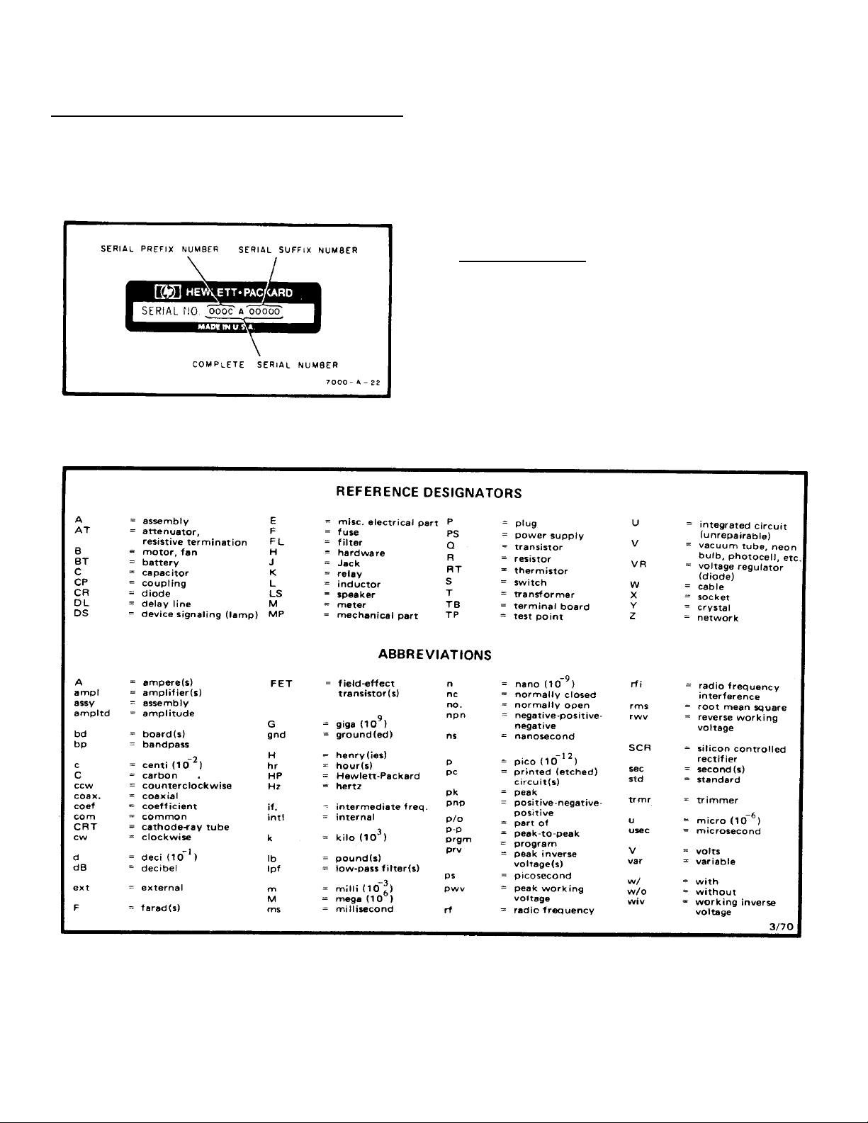
1-15. INSTRUMENT AND MANUAL IDENTIFICATION.
1-16. This manual applies directly to Model 141T
instruments with a serial prefix num ber as listed on the
manual title page, The serial prefix number is the first
group of digits in the instrument serial number (f igure 1-
2). The instrument serial number is
Figure 1-2. Instrument Serial Number
Table 1-2. Reference Designators and Abbreviations
1-17 Check the serial prefix number of the instr ument.
If the serial prefix num ber is diff erent from that listed on
the title page of this manual, refer to Section VII for
instructions to adapt this manual for proper instrument
coverage.
1-18. Errors in the manual are listed under errata on an
enclosed MANIUAL CHANGES sheet (if any).
1-19. INQUIRIES.
1-20) Refer any questions regarding the manual, the
change sheet, or the instrument to the nearest HP Sales
/Service Office. Always identify the instrum ent by model
number, complete nam e, and complete serial num ber in
all correspondence. Refer to the inside r ear c over of this
manual for a world-wide listing of HP Sales/Service
Offices
1-3
TM 11-6625-2781-14&P
Time Domain Reflectometry.
1-4
TM 11-6625-2781-14&P
Model 141T Installation
SECTION II
INSTALLATION
2-1. INTRODUCTION.
2-2. This section contains instructions for perf orming an
initial inspection of the Model 141T. Installation
procedures and precautions are presented in step-bystep order. The procedures for making a claim for
warranty repairs and for repacking the instrument for
shipment are also described in this section.
2-3. INITIAL INSPECTION.
2-4. The instrument was inspected mechanically and
electrically before shipment. Upon receipt, inspect it f or
damage that may have occurred in transit. Check for
broken knobs, bent or brok en connectors, and dents or
scratches. If damage is found, refer to the claims
paragraph in this section. Retain the packing material for
possible future use.
2-5. Check the electrical perf ormance of the instrument
immediately after receipt. Refer to Section V for the
performance chec k procedure. The performance chec k
will determine whether or not the instrument is operating
within the specifications listed in table 1-1. Initial
performance and acc uracy of the instrum ent are certif ied
as stated on the inside front cover of this manual. If the
instrument does not operate as specified, refer to the
claims paragraph in this section.
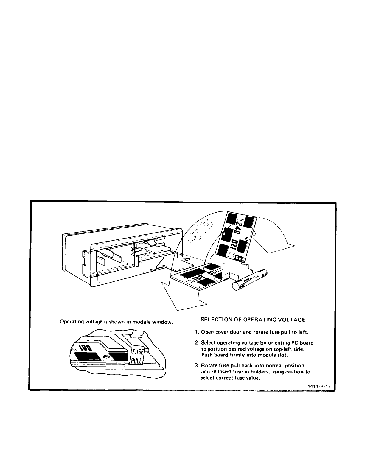
2-6. PREPARATION FOR USE.
2-7. The instrument requires a power source of 100-,
120-, 220-, or 240-volt +5 - 10o, single phase, 48 to 440
Hz, that can deliver approximately 400 volt-amperes. A
removable jumper board in power module A7, provides
selection of the line voltage to be used (figure 2-1).
Figure 2-1. Voltage Selection
2-1
TM 11-6625-2781-14&P
Installation Model 141T
CAUTION
Before placing the Model 141T in operation, ensure that
the operating voltage indicated in the power module
window (figure 2-1) agrees with the line voltage being
used.
To avoid damaging CRT perform Intensity adjustment
(figure 3-2).
2-8. When oper ating the Model 141T from a 1OOV or
125V source, replace line fuse with a 4A slow-blow f use
When operating from a 220V or 240V source, replace
line fuse with a 2A slow-blow fuse.
2-9. THREE-CONDUCTOR AC POWER CABLE.
2-10. For the protection of operating personnel HewlettPackard Company recommends that the instrument
panel and cabinet be grounded. This instrument is
equipped with a three-conductor, ac power cable that,
when connected to an appropriate receptacle. grounds
the instrument through the offset pin. The power jack
and mating plug of the power cord meet International
Electro-technical Commission (IEC) safety standards.
plastic trim in place Four supports are mounted on the
rear panel of the instrument for operation in a vertical
position. Top, left side, and bottom panel covers can he
removed, giving access to components and
adjustments. Allow suff ic ient spac e around the c abinet
for air circulation.
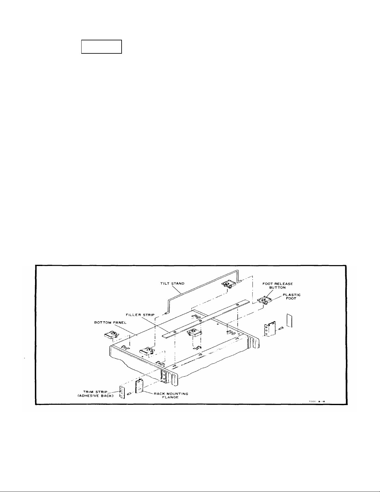
2-1:1. A kit for converting the modular cabinet to a
rack mount is included Instructions for making the
conversion are given Below figure 2-2).
a Detach tilt stand by pressing away from front feet
A.
b. Remove plastic feet by pressing metal button
and sliding each foot free.
c. Using thin-bladed tool, remove aluminum trim
strips. These strips have adhesive backing, and are
located on sides behind front handles.
d. Attach rack mounting flange, using screws
provided in kit, in each space where trip strip was
removed. Position large notch of flange at instrument
bottom.
2-11. INSTRUMENT MOUNTING.
?-12. The instrument is shipped from the factory as
a bench instrument with the tilt stand, feet, and
e. Rack mounting kit contains filler strips that s hould
be used as spacers between Model 141t and other
equipment mounted in same rack.
Figure 2-2. Rack Mounting Procedure
2-2

TM 11-6625-2781-14&P
Installation Model 141T
2-14. INSTRUMENT COOLING.
2-15. Forced-air cooling is used to m aintain the required
operating temperatures within the instrument The air
intake and filter are located on the r ear of the instrument.
Warm air is exhausted through the side-panel
perforations. Allow at least 3 inches of clearanc e around
the top, rear, and both sides of the instrument for
cooling.
2-16. The cooling fan does not require lubrication, but
the filter should be cleaned often enough to ensure
sufficient air flow. A thermal switch is mounted on the
fan to protect against over-heating.
2-17. CLAIMS.
2-18. The warranty statement applicable to this
instrument is printed inside the front cover of this
manual. Refer to the rear of this manual for the CRT
warranty statement. If physical damage is found
or if operation is not as specified when the instrum ent is
received, notify the carrier and nearest HP Sales/Service
Office im mediately (refer to the list in back of this manual
for addresses). The HP Sales/ Service Office will
arrange for repair or replacement without waiting for
settlement of the claim with the carrier.
2-19. REPACKING FOR SHIPMENT.
2-20. If the instrument is to be shipped to a HewlettPackard Sales/Service Off ice f or ser vice or r epair, attach
a tag showing owner (with address), complete instrument
serial number, and a description of the service required.
2-21. Use the original shipping carton and packing
material. If the original pack ing m aterial is not available,
the Hewlett-Packard Sales/Service Office will provide
information and recommendations on materials to be
used.
2-3/2-4

TM 11-6625-2781-14&P
Operation Model 141T
SECTION III
OPERATION
To externally modulate the trace intensity, set the switch
3-1. INTRODUCTION.
3-2. This section contains front panel c ontrol inf orm ation
and considerations for operating the instrument.
Controls for operation of power supplies and c athode-ray
tube are located on the instrument fr ont panel. All other
controls are located on the plug-in units. T he inst rument
includes high and low-voltage power supplies, a
calibrator circuit, a CRT, and a pulse circuit for variable
persistence and storage operation.
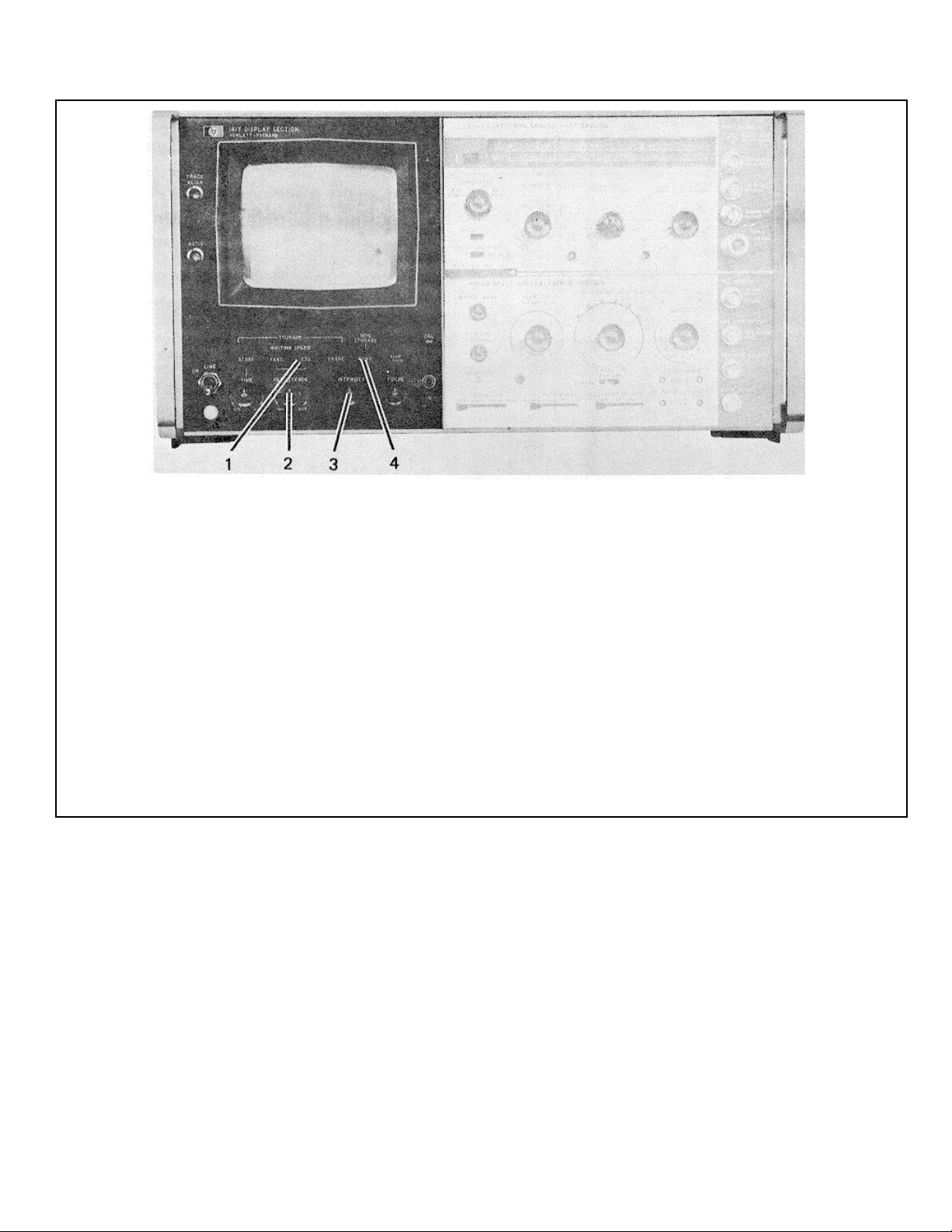
3-3. CONTROLS AND CONNECTORS.
3-4. figure 3-1 identifies the front panel controls and
gives a brief functional description of each. The
following paragraphs provide detailed descriptions of
controls with multiple or complex functions.
3-5. TRACE ALIGN.
3-6. The TRACE ALIGN adjustment compensates for
external magnetic fields that affect alignment of the
horizontal trace with the graticule. The alignment should
be checked when the instrument is moved to a new
location and adjustment made when necessary.
3-7. BEAM FINDER.
3-8. A high dc input signal may drive the trace off the
CRT screen. When the BEAM FINDER push-button is
pressed, the trace will be returned to the screen
regardless of the setting of horizontal or vertical
POSITION controls. If pressing the BEAM FINDER
pushbutton does not return a beam to the viewing area
press and hold the BEAM FINDER and gradually adjust
the INTENSITY control until a visible trace is obtained
and release BEAM FINDER. When used with 8550series frequency domain plug-ins, the BEAM FINDER
has no function.
to EXT, and connect the modulation signal to the
terminals. The am plitude of the pulse required to blank
the trace depends on the front panel INTENSITY control
setting, and is approximately 20 volts positive for normal
intensity settings. When not using ex ternal modulation,
set the switch to INT.
3-13. PLUG-IN UNITS.
3-14. Available plug-ins for the Model 141T ar e listed in
table 1-2. This instrument is norm ally operated with an
RF section plug-in in the upper compartment and IF
section plug-in in the lower compartment. The Operating
and Service Manuals for the plug-in units contain
detailed information for installing plug-ins.
3-’5. Arrangement of plug-ins can be selected to suit
special applications. For example, a vertical amplifier
and time base plug-in can be reversed s o that sweep is
vertical and signal deflection is horizontal. A vertical
plug-in can be used in each compartment to take X-Y
measurements.
3-16. Double-sized plug-ins, such as the Model 1415A
and Model 1416A, can be inserted into the instrument
after removal of the divider shield between lower and
upper compartments. Blank plug-ins, both single and
double size, are available for customer fabrication of
specialized vertical amplifier and time base plug-ins.
Refer to table 4-1 for power supply current limitations.
NOTE
For proper operation, the divider
shield must be in place when using
standard size plug-ins (does not apply to
spectrum analyzer plug-ins).
3-9. FOCUS AND ASTIGMATISM.
3-10. These controls provide uniform focus of the trace
over the entire CRT screen. Adjustment is m ade in the
STD W RITING SPEED with a low intensity spot on the
CRT screen. FOCUS and ASTIG are adjusted for a
round, sharply focused spot.
3-11. Z-AXIS INPUT.
3-12. The Z-AXIS INPUT jack and selector switch are
on the rear panel of the instrument (figure 6-3).
3-17. The Model 141T also accepts Model 1400-ser ies
plug-ins for standard oscilloscope use. W hen standard
1400-series oscilloscope plug-ins are used, plug-in
shield (HP Part No. 00140-0601) must also be-used.
Order the shield from the nearest HP Sales/Service
Office.
CAUTION
Do not operate instrument above 450C,
when using real time plug-ins.
3-1

TM 11-6625-2781-14&P
Operation Model 141T
1. TRACE ALIGN: Adjustment to set trace parallel to
horizontal graticule lines.
2. ASTIG. Adjustment to set roundness of CRT
beam.
3. LINE: ON position connects ac power to
oscilloscope and lights indicator.
4. STORE. Retains displayed signal at reduced
intensity for viewing at a later time.
5. TIME. Control for setting storage time length.
6. FAST. Operates CRT at maximum writing s peed
with variable persistence.
7. PERSISTENCE: Controls endurance time of
displayed signal.
Figure 3-1. Model 141T Controls and Connectors
8 STD: Operates CRT at norm al writing speed with
variable persistence.
9. ERASE’: Removes stored or written displays.
10. INTENSITY. Control for setting intensity of CRT
display.
11. CON: Selects operation as standard oscilloscope.
12. FOCU’S: Control for focusing beam on CRT.
13. BEAM FINDER: Returns beam to CRT screen
regardless of deflection potentials when used with
400-series time-dom ain plug-ins. When used with
8550-series frequency-domain plug-ins , the BEAM
FINDER pushbutton has no function.
11. CAI: I-volt and 10-volt p-p, calibrated square wave
outputs.
3-2
TM 11-6625-2781-14&P
Operation Model 141T
VARIABLE PERSISTENCE MODE
1. Press STD pushbutton.
2. Rotate PERSISTENCE control fully ccw.
3. Adjust INTENSITY to less than that intensity which
just eliminates trace blooming.
Trace blooming (figure 3-5) indicates ex cessive INTENSITY that can damage the CRT. Bloom ing does
not occur in the CONV mode. Do not increase intensity when in CONV mode. Always repeat above
procedure each time sweep speed or input signals change.
Figure 3-2. Intensity Adjustment
CONVENTIONAL
1. Press STD pushbutton.
2. Rotate PERSISTENCE control fully ccw.
3. Adjust INTENSITY to less than that intensity which
eliminates trace blooming.
4. Press CONV pushbutton. Do not increase
INTENSITY.
CAUTION
3-3

TM 11-6625-2781-14&P
Operation Model 141T
3-18. Slight differences in CRT sens itivities, m ay require
readjusting the sensitivity calibration of plug-ins installed
in the instrument for the f irst time, or when moved from
one display section mainframe to another. Ref er to the
Operating and Service Manual of the plug-in for the
required adjustment procedure.
3-19. OPERATING CONSIDERATIONS.
3-20. DEFINITIONS.
3-21. The definition of som e words and phrases used in
this manual may vary slightly from com mon usage. The
definitions of these words and phrase are as follows:
a. Write. To transform an input signal into visible
display on the CRT screen.
b. Persistence. The length of time a s ingle sweepwritten display remains visible on the CR’T screen
(intensity and sweep time constant).
c. Store. To retain, at reduced intensity, a display
which has been written on the CRT.
d. Erase. To rem ove all displays and blooms that
have been stored or written with persistence on the CRT.
e. Intensity. The brightness of a display as it is
written on the CRT screen (persistenc e and sweep time
constant).
f. Bloom. A visible, non-symm etrical expans ion of a
display written on the CRT screen, figure 3-5.
g. Fade positive. Appears as random green areas
on a dark background in MAX PERSISTENCE mode,
figure 3-7.
h. Background illumination. A green cloud of
illumination visible on the CRT screen, figure 3-7.
i. Sweep time. The time (in seconds, m illiseconds,
or microseconds) required for the beam to move
horizontally one unit of distance (division) across the
CRT screen, when writing a display.
j. Fadenegative. A condition in which a portion of
the trace or screen begins to dim.
k. Burn. A burn is permanent dam age to the CRT
phosphor or mesh resulting from excessive intensity
being maintained for too long a period. Phosphor bur ns
appear as a discolored area on the CRT scr een. Mesh
burns appear as spots or traces that are darker than the
background illumination in the MAX PERSISTENCE,
FAST WRITING SPEED modes.
which just eliminates any trace blooming with
minimum PERSISTENCE setting.
3-23. Persistence and intensity determine the duration of
display afterglow. Always set PERSISTENCE and
INTENSITY as shown in figure 3-2. The PERSISTENCE
control sets the rate that a display is erased; INTENSITY
sets the brightness of the trace as it is written. With a
given PERSISTENCE setting, the actual duration of trace
afterglow may be increased by increasing the
INTENSITY. The PERSISTENCE control sets the rate of
erasing a written display. The brighter a trace the more
time required to erase the display. Conversely, a display
of low intensity will erase more rapidly. The same
principle applies to a stored display of high and low
intensity.
3-24. Pressing STORE pushbutton permits a written
display to be stored at reduced intensity in the
oscilloscope for comparison, measurement, or
photography at a later time. Selection of the STORE
configuration disconnects STD, FAST, ERASE,
INTENSITY, PERSISTENCE, and CONV functions.
3-25. The TIME control varies the length of time a
display is stored. The time ranges from 15 seconds,
minimum TIME control setting when writing in FAST
speed and transferring to STORE; to over 2 hours,
maximum TIME control setting when writing STD speed
and transferring to STORE. Light output is inversely
proportional to storage time.
3-26. When the STD WRITING SPEED is used,
pressing ERASE pushbutton establishes the CRT in a
condition for variable persistenc e display of a signal that
later can be stored. Use the m inimum INT ENSITY and
maximum PERSISTENCE required to obtain the desired
display. The STD and FAST writing speeds are the only
configurations that a variable persistence dis play can be
written.
3-27. When FAST W RITING SPEED is used, pres sing
ERASE primes the CRT stor age surface to allow faster
writing on the storage surface. The display however, has
reduced contrast and fades positive more rapidly.
Contrast and storage time are also reduced.
3-22. CONTROL FUNCTIONS.
CAUTION
Excessive intensity may damage the CRT
storage mesh. The INTENSITY setting for any
sweep speed should be less than that intensity
3-28. Pressing ERASE pushbutton removes stored or
written displays from the CRT in either FAST or STD
modes. A display that has been stored or written at a
high level of INTENSITY may remain
3-4
TM 11-6625-2781-14&P
Operation Model 141T
visible after ERASE pushbutton has been released It
may be necessary to press and release ERASE
pushbutton more than once to com plete erasure of high
intensity displays.
3-29. Selection of CONV operating mode, dis ables the
variable persistence and storage functions and the
instrument operates as a c onventional, general purpose,
oscilloscope. Always adjust INTENSITY in STD mode
with minimum PERSISTENCE so the display does not
bloom, then switch to CONV. The PERSISTENCE
control does not function in CONV mode.
3-30. OPERATING PROCEDURES.
NOTE
After applying power, allow instrument
15 minutes warm up before attempting
to make measurements.
3-31. These operating procedures will familiarize the
operator with instrument controls and aid in obtaining
desired CRT display.
a. To improve persistence unif ormity in STD mode
adjust A5R45, STD collimator adjust. This will reduce
size of useable display area.
b. For variable persistence operation, use minim um
INTENSITY and maximum PERSISTENCE compatible
with desired display (figure 34).
c. Use WRITING SPEED in FAST mode only for
fast sweep time, single-shot displays, or to improve
uniformity of trace intensity. FAST WRITING SPEED
mode causes more rapid positive fading on CRT and
reduced persistence or storage time.
d. To store a display, press STD pushbutton and
adjust INTENSITY and PERSISTENCE for desired
display and press STORE.
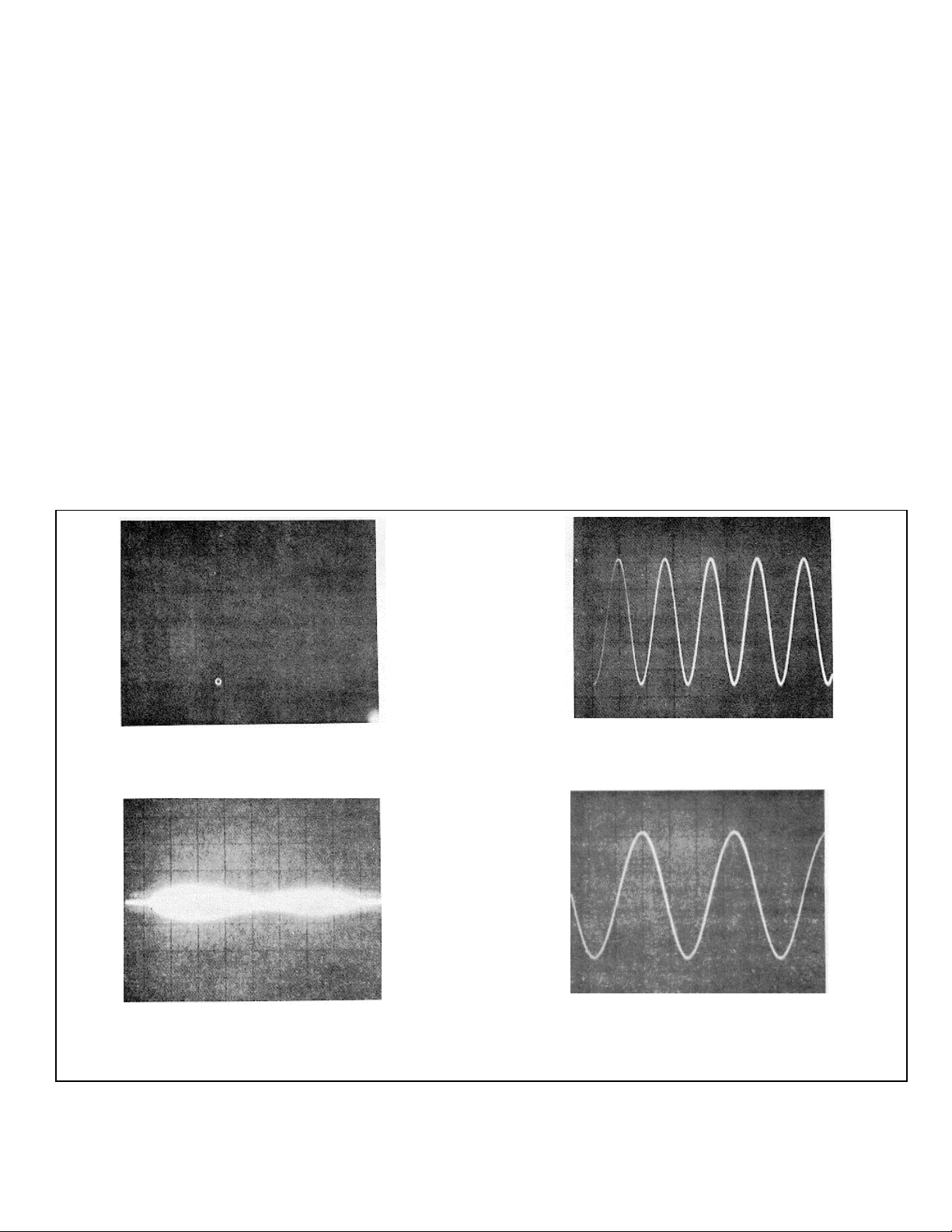
Figure 3-3. Background illumination immediately after
erasing with WRITING SPEED in FAST and
P’ERSISTENCE to MAX
Figure 3-5. Single-shot trace bloom caused by
INTENSITY and/or PERSISTENCE set too high
Figure 3-4. Variable persistence with a slow, repetitive
sweep
Figure 3-6. Single-shot display with INTENSITY and
PERSISTENCE set the same as figure 3-5 and
increased amplitude
3-5
TM 11-6625-2781-14&P
Operation Model 141T
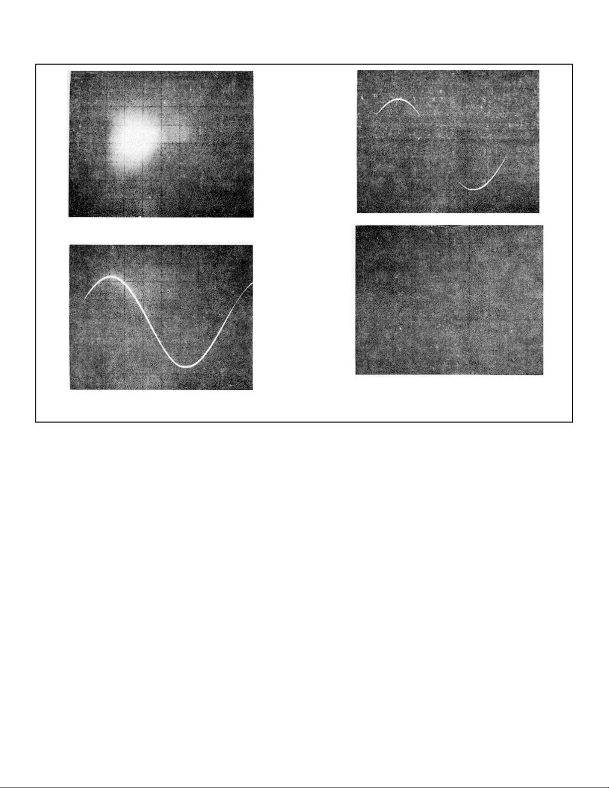
Figure 3-7. Fade positive after 2 to 4 minutes in STD
mode.
Figure 3-9. Same display as figure 3-8 after three
minutes in STD mode
e. To view a stored display, adjust TI ME contr ol until
stored display has desired brightness
f. To store more than one display, press STD
pushbutton, set PERSISTENCE fully cw and INT ENSITY
as required; allow first display to be written on CRT. Set
INTENSITY fully ccw, and connect second signal to be
stored. Reset vertical POSIT ION if s econd display is not
to be superimposed on first Slowly rotate INTENSITY
clockwise until second display appears. Press STORE
pushbutton and both displays will be stored.
g. A display stored when instrument power is turned
off will remain stored for several days. To observe a
stored display, press STORE, set the verti-
Figure 3-8. Single-shot 20 usec/div display
Figure 3-10. Small bright spots caused by minute
imperfections in storage mesh
cal position control ccw before turning on the instrum ent.
Then adjust the TIME control until the stored display is
visible.
h. To erase stored displays, press STD or FAST
and rotate the PERSISTENCE control fully ccw, or press
ERASE for approximately one second, then release.
(First method is not ef fective when W RITING SPEED is
set to FAST).
3-32. SINGLE-SHOT OPERATION.
3-33. To write with persistence or store a single-shot
phenomena, trial setting of INTENSITY is the best
approach. The amplitude of the phenomena and the
sweep-time required to display it will affect the
3-6

TM 11-6625-2781-14&P
Operation Model 141T
persistence. For example, with maximum
PERSISTENCE and some settings of INTENSITY, a
single -shot straight-line trace may bloom as shown in
figure 3-5, while a single-shot signal with amplitude
variations of several divisions may not cause blooming
(figure 3-6). To determ ine the best INTENSIT Y setting,
connect a signal which approximates the sweep time and
amplitude of the single-shot signal to be written. Set
PERSISTENCE fully cw and trigger a single sweep of the
test signal. Set the INTENSITY as far cw as possible
without causing blooming. Repeat the single sweep
signal, erasing the display and setting the INTENSITY
after each trace until the desired display is obtained.
This setup should give maximum persistence to the
single-shot display. After the single-shot signal has been
written, the display may be retained by pressing STORE
and setting the TIME control to MAX.
3-34. Single-shot signals which require a beam speed
faster than 50 microseconds per division can be
written with more brightness by setting the WRITING
SPEED to FAST. The screen will be unevenly
illuminated after erasing when WRITING SPEED is in
FAST, however, the INTENSITY can be set high enough
to make the display visible through the illumination. A
display, written with WRITING SPEED set to FAST, will
be obscured by positive fading more rapidly than a
display written with WRITING SPEED set to STD.
3-35. Single-shot signals which require a beam speed
between 20 and 200 microseconds per division may
have low brightness at some location on the screen. Fire
a single-shot test signal with INTENSITY and
PERSISTENCE fully cw and WRIT ING SPEED in STD,
and if the center brightness is low, wait for one to three
minutes for the low-brightness area to become brighter.
Likewise, if the entire display brightness appear s below a
usable level, or the display is not visible at all, wait for
one to five minutes for the display to appear (figures 3- 8
and 3-9).
3-7/3-8
TM 11-6625-2781-14&P
Theory Model 141T
SECTION IV
PRINCIPALS OF OPERATION
4-1. INTRODUCTION.
4-2. This section contains f unctional descriptions keyed
to an overall block diagram of the instrum ent, and circuit
descriptions keyed to simplif ied block diagram s of circ uit
groups. The schematics are located in Section VIII.
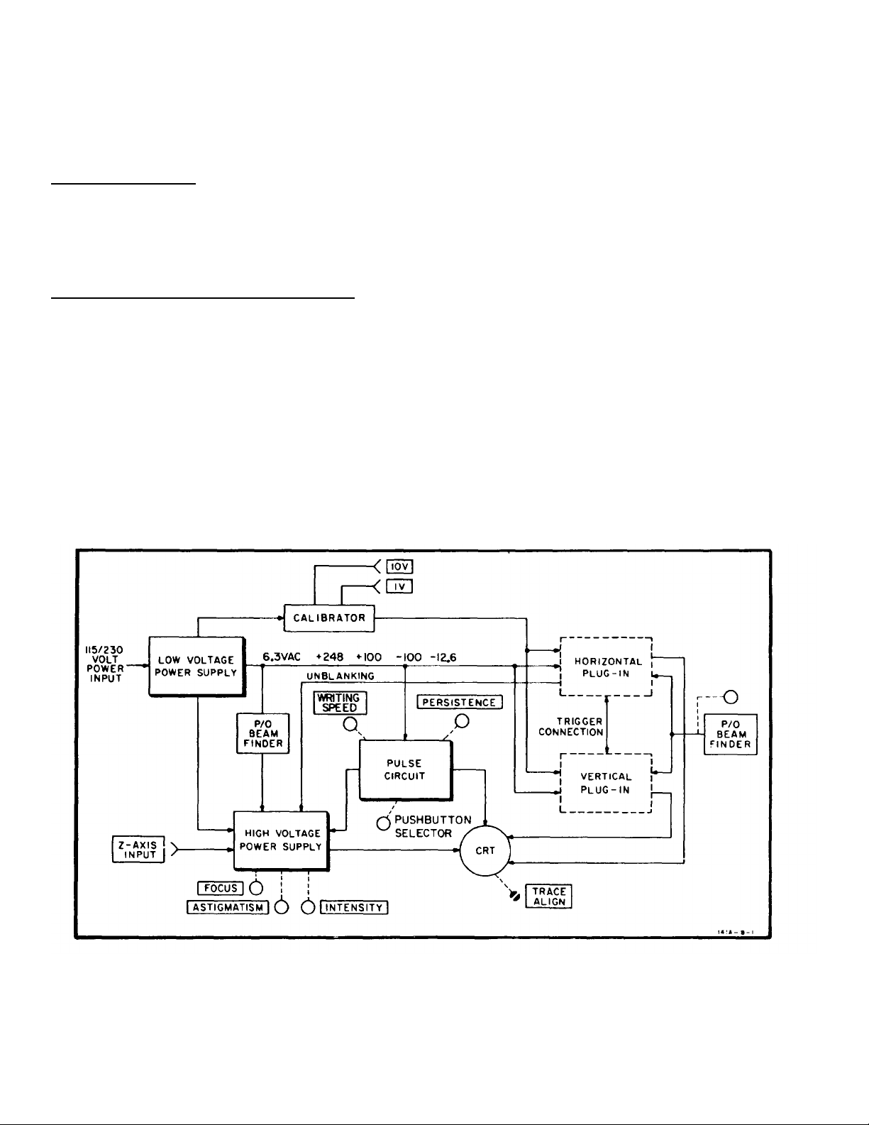
4-3. OVERALL FUNCTIONAL DESCRIPTION.
4-4. The Model 141T Display Section has five main
circuits (figure 4-1): low-voltage power supply, highvoltage power supply, calibrator circuit, pulse circ uit, and
horizontal driver circuit. The horizontal and vertical
amplifier circuits are in the plug-in units.
4-5. LOW-VOLTAGE POWER SUPPLY.
4-6. The low-voltage power supply operates on 100,120-, 220- or 240-volts, single phase, 48-440 Hz.
Output voltages are -12.6-, -100-, +100- and +248-volts
dc. All outputs are fused and electronically regulated.
Voltages are distributed to the high-voltage power
supply, calibrator, pulse circuits, and horizontal and
vertical plug-ins. The low voltage transformer supplies
6.3 Vac to the main filament of the CRT and to the
calibrator circuit.
4-7. CALIBRATOR.
4-8. The 6.3 Vac is applied to the calibrator circuit where
it is shaped into a square wave (of line frequency) and
applied to two front-panel connectors, 1V and 10V pk-pk.
The 1-volt output is also applied to the vertical and
horizontal plug-ins for sensitivity calibration. Accurac y of
the calibrating signals is 1%.
4-9. HIGH-VOLTAGE POWER SUPPLY.
4-10. A transistorized oscillator and a step-up
transformer are used to generate negative and positive
high voltages for the CRT. The negative 2350-volt
supply is electronically regulated.
Figure 4-1. Model 141T Block Diagram
4-1
TM 11-6625-2781-14&P
Theory Model 141T
4-11. PULSE CIRCUIT.
4-12. This circuit generates pulses of variable level and
rate. These pulses and other dc voltages from the circuit
are applied to the storage and persistence elements in
the CRT. The low-voltage power supply provides all
operating power for the pulse circuit.
4-13. HORIZONTAL DRIVER CIRCUIT.
4-14. The horizontal driver is an impedance converter
circuit. The output from the horizontal am plifier circuit in
the plug-in unit is applied to the input of the horizontal
driver circuit, which in turn drives the horizontal plates of
the CRT.
4-15. CIRCUIT DESCRIPTION.
4-16. LOW-VOLTAGE POWER SUPPLY.
4-17. The low-voltage power supply consists of +100volt supply, -100-volt supply, +248-volt supply and -12.6volt supply. The +100-volt supply is independent and
provides a reference voltage for the -100-volt supply.
The +248-volt and -12.6-volt supplies are dependent on
the -100-volt supply for reference voltages.
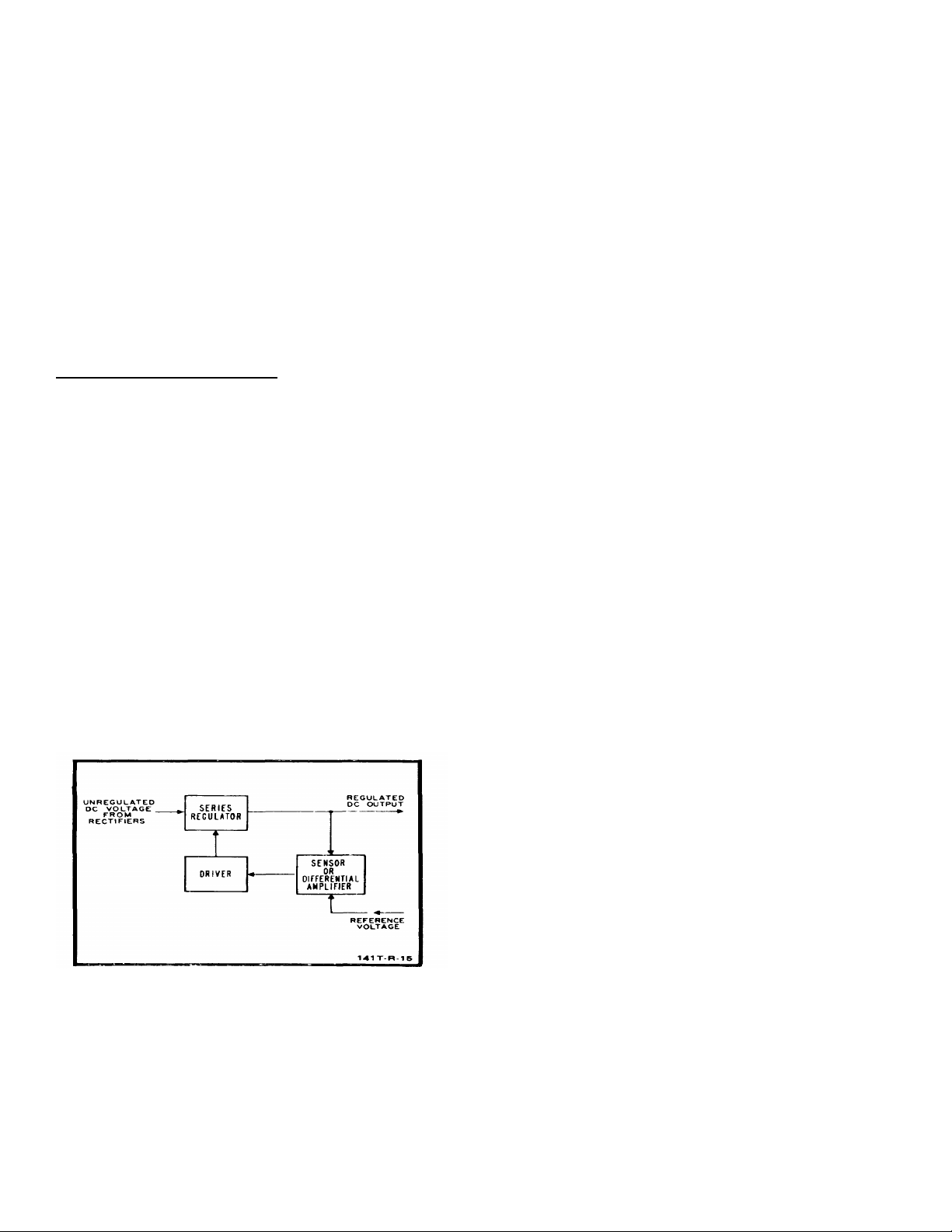
4-18. figure 4-2 is a simplified block diagram of the
regulator used in the low-voltage supply. The series
regulator acts as a variable resistance in the regulated
output. A sensor (or diff erential amplifier) c ompares the
output voltage with a reference voltage. The driver
(emitter follower or amplifier) controls the bias on the
series regulator, which effectively controls the series
resistance. Any change in output voltage is fed bac k to
the series regulator. The change in series resistance
and the resulting voltage drop is opposite to the output
voltage change, maintaining the output voltage at a
constant level.
applied to the primary of TI through an on-off switch, a
fuse and a thermal switch. Pilot lam p DS1, lights when
power is applied to T1. Two shunt resistors are
connected to the +248-volt supply to reduce series
regulator power dissipation when high-current plug-ins
are used. Each shunt is wired to a rear panel connector.
The internal wiring of the plug-in determines whether the
shunt is in the circuit or not.
4-20. +100-Volt Supply.
secondary ofT1 is rectified by A1CR5-AICR8 and
partially filtered by C3 and A2R17. The resulting dc
voltage is applied through the series regulator Q2, to the
output. Differential amplifier A2Q4/A2Q5, com pares the
voltage across A2V1 with a sample of the output voltage.
Any change in output voltage is applied to the base of
driver A2Q3, which controls the bias on regulator Q2.
Series regulator Q2, compensates for the change in
output voltage by changing resistance and restores the
output level to normal. The +100-volt output is adjusted
by A2RllB and fuse A2F2 provides overload protection.
4-21. -100-Volt Supply.
volt supply is taken from the output of the +100-volt
supply. The reference voltage across A2R31 is
compared with a sample of--100-volt output across
A2R35. The error voltage sensed by differential amplifier
A2Q7/A2Q8 is applied through driver A2Q6, and series
regulator Q3. The series regulator brings the -100 volt
supply back into proper balance with respect to the
+100-volt supply. Ac voltage from T1 is rectified by
A1CR9-A1CR12, partially filtered by C4/C5/A2R27, and
the resulting dc voltage is applied by the series regulator
Q3, to the -100-volt output. Regulation is obtained as in
the +100-volt supply. A2R11C adjusts the -100-volt
output, and fuse A2F3 provides overload protection.
4-22. +248-Volt Supply.
+248-volt supply senses any variation in the output
voltage with respect to -100 volts. The err or voltage is
amplified by driver A2Q1, which applies corrective bias to
series regulator Q1. A2RllA adjusts the +248-volt output
and fuse A2F1 provides overload protection. A2CR4
provides temperature compensation for A2Q2, and is
normally forward-biased.
The ac voltage from the
Reference voltage for the -100-
Sensor amplifier A2Q 2, in the
Figure 4-2. Regulated Power Supply Block Diagram
4-19. figure 8-10 is a schematic diagram of the low
voltage power supply. The primary winding is wired
through a rear panel power module for conversion to
100-, 120-, 220- or 240-Vac operation. Line voltage is
4-23. -12.6-Volt Supply.
senses any variation of output voltage with respect to 100 volts and applies the error voltage to driver am plifier
A2Q9. The driver increases signal current to the level
required to control series regulator Q4. The -12.6-volt
output is adjusted by A2R47A. Current limiter A2Q10 is
a protective circuit for the series regulator and is
normally biased off. If an overload occurs across the -
12.6-volt output, the base of
4-2
Sensor amplifier A2 Q11
TM 11-6625-2781-14&P
Theory Model 141T
A2(Q10 goes positive by the voltage drop across R11,
minus the forward voltage drop acros s A2CR16, turning
A2Q(10 on. The collector of A2Q10 is applied through
A2Q9 to the base of series regulator Q4, reducing the
current flowing through Q4. The current flows through
an external overload which limits the c urrent required to
keep A2QIO on. Additional over-load protection is
provided by fuse, A12F4.
4-24. CALIBRATOR.
4-25. The calibrator circuit ( f igure 8- 10) cons is ts of three
parts: a tunnel diode (square wave generator), ;1
transistor switch, and a calibration network.
4-26. Input to tunnel diode A2CRI9, is applied through
A2R5.0. The tunnel diode generates a square wave at
line frequency. Transistor switch A2Q12, is off during
the time of the positive half-cycle of the square wave
(when the voltage at the base is close to zero), and the
collector voltage is at a level set by breakdown diode
A2VR6 and resistor A2R47B. W hen the negative-going
portion of the square wave is applied to the base of
A2Q12, the transistor increases conduction, effectively
shorting the collector to ground. The output of the
calibrator becomes zero. At the end of the negative input
half-cycle (bias of A2Q12 returns to zero) the transistor is
turned off, and the output returns to its previous value.
4-27. Tunnel diode bias current is supplied through
A2R51. The bias current sets an operating level for the
diode which ,affects the symmetry of the square wave
output. Cal adj A2R47R, is used to set the dc
voltage at the collector of A2Q12 to -10 volts when the
transistor is off Breakdown diode A2VR6 reduces the
output impedance, and provides the temperature
compensation for the circuit. Voltage divider
A2R55, reduces the 10-volt output to 1 . Roth 10- and I volt outputs are available at the front panel of the
instrument, and the 1-volt output is available to both
plug-ins.
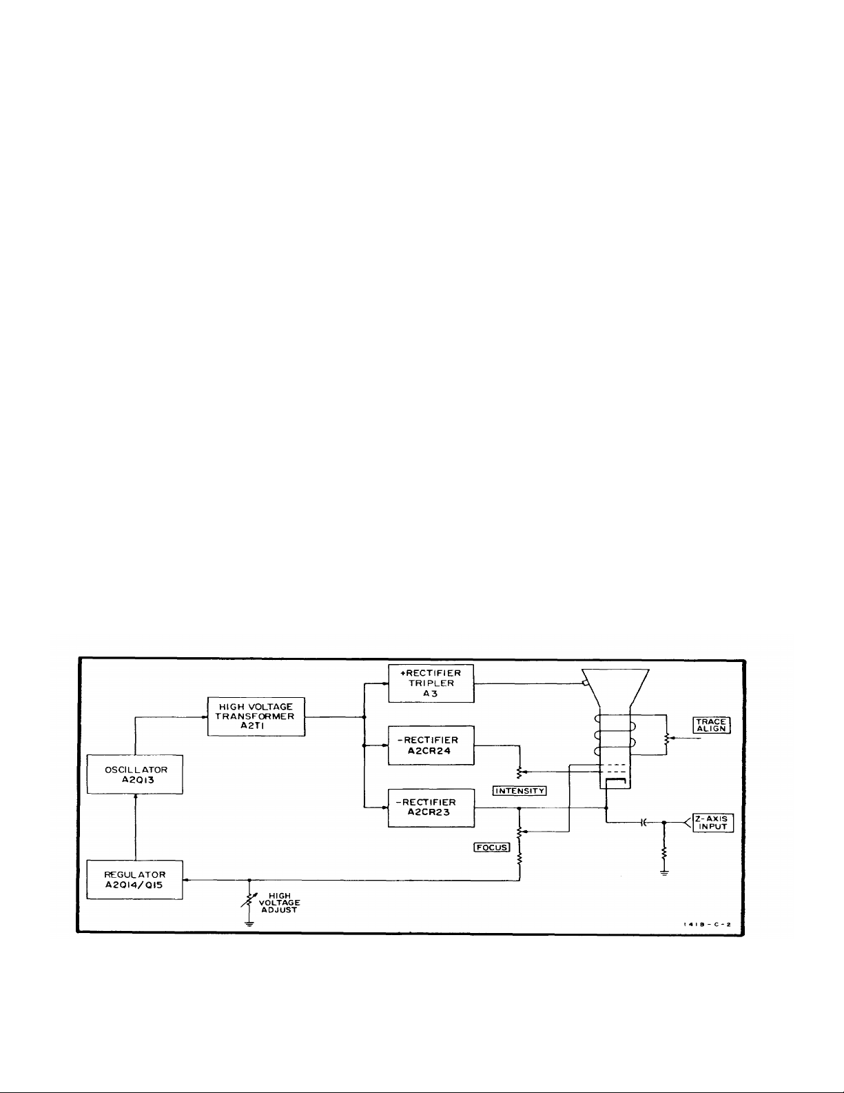
4-28. HIGH-VOLTAGE SUPPLY.
4-29. figure 4-3 is a block diagram of the high-voltage
power supply. The output of a regulated transistor
oscillator is stepped-up in voltage and applied to a ser ies
of high voltage rectifiers. The positive output of the
voltage tripler is connected to the post-ac celerator of the
CRT. The negative output voltages are used in the gun
assembly of the CRT and its associated controls . T he Zaxis input can be used to apply intensity modulating
signals to the CRT.
4-30. figure 8-13 is a schematic diagram of the highvoltage supply and the CRT. Oscillator A2Q12 operates
at a frequency of approximately 32 kHz. Any change in
the output voltage is applied to A2Q15, which converts
the voltage change to a current change. This current
change is applied, by emitter follower A2Q14, to the base
of the oscillator transistor . The amplitude of oscillations
is changed in such a direction as to oppose the original
output voltage change. high-voltage adjust A2R6:3 sets
the amplitude of oscillation to produce the cor rect output
voltage.
A2R;54
,’
Figure 4-3. High-Voltage Power Supply Block Diagram
4-3

TM 11-6625-2781-14&P
Theory Model 141T
4-31. Two separate negative supplies are used, one for
the control grid of the CRT, and one to provide the CRT
cathode and focusing voltages. Both supplies use half wave rectifiers (A2CR23 and A2CR24). T he unblanking
gate from the horizontal plug-in (pin 1, J2) is applied to
the return side of the grid supply, and changes the
negative grid voltage by about +50 volts to unblank the
trace. A positive pulse of about 20 volts will blank the
trace when applied to Z-axis input. When Z-axis input is
not used, S4 is set to INT to rec eive chopped blanking
from a dual-trace plug-in.
4-32. The voltage tripler circuit provides the 6.6 kV postaccelerating voltage applies to the CRT.
4-33. The ASTIG adjustment, R8, adj us ts the roundnes s
of the spot, and the geometry adjustment, A2-R72, is
used to optimize pattern shape.
4-34. STORAGE CRT.
4-35. Refer to figure 8-13 for the schematic diagram of
the storage CRT, VI. The CRT contains the conventional
electron (writing) gun, deflection plates, post-acc elerator,
and phosphor screen. In addition, there are two
floodguns, a collimator, a collec tor mesh, and a storage
mesh. These added elements make possible the
variable persistence and storage functions of the
instrument.
4-36. Flood Guns.
electron gun, outside of the horizontal deflection plates.
Horizontal drivers, A6QI and A6Q2, prevent flood gun
electrons from flowing through the deflection plates to
the output stage of the plug-in. The guns operate
continuously when the power switch is ON. An electron
cloud, that is emitted by the flood guns, is accelerated
toward the CRT screen by collimator and collector m esh
voltages. These electrons make stored or persisting
display visible. They are also used to erase stored and
persisting displays.
4-37 Collimator.
along the tapered portion of the CRT. A positive voltage
applied to the collimator focus es the f lood-gun electr ons.
The flood-gun electrons are formed into a column
perpendicular to, and approximately equal to the width of
the CRT screen.
4-38. Collector Mesh.
the flood guns and the storage mesh (closer to the
storage mesh). It is always positive with respect to the
storage mesh except in the ERASE mode of operation;
both are then at the same potential. In addition to
accelerating flood gun electrons, the collector m esh also
repels positive ions generated by the flood guns.
4-39. Storage Mesh.
the CRT screen and is coated with non-conducting
material. It is statically held at a slightly positive potential
(approximately +3 volts). W hen the electron beam from
the writing gun strikes the mesh coating, secondary
electrons are emitted. T his secondary emission creates
Two flood guns are located on the
The collimator is an internal coating
The collector mesh is between
The storage mes h is just behind
a pattern of positive potential identical to the m ovement
of the beam. Flood gun electrons are accelerated by this
positive potential pattern and strike the phosphor scr een,
creating a visible display.
4-40. The storage mesh is pulsed with pulses of
approximately 10 microseconds duration. T hese pulses
erase the positive pattern on the storage mesh by
discharging the mesh coating. Time required for this
erasing operation is determined by the pulse repetition
rate. The positive pattern on the mesh may also be
neutralized manually by connecting the collector and
storage meshes (erase). The high positive potential
(approximately +156 volts) allows more uniform
discharging of the surface. When the storage mesh is
disconnected from the collector m esh and r eturned to +3
volts, the coated surface is at a uniform ly equal potential
of--9 volts. In both cases, the screen has no illumination.
The pattern may be lost by the storage mesh fading
positive and allowing the entire screen to be illum inated.
This occurs when positive ions from the flood gun raise
the surface potential of the storage mesh in random
areas sufficiently to allow flood gun electrons to strike the
screen.
4-41. PULSE CIRCUIT.
4-42. figure 4-4 is a simplified block diagram of the
pulse circuit. The pulse circuit supplies pulses of
variable repetition rate to control the operation of the
CRT. The pulse timer generates a pulse which trigger s
the monostable multivibrator. The two outputs of the
monostable multivibrator are applied to the flood gun
driver and output pulser. The flood gun driver applies
pulses to the accelerator of the CRT to control storage
time of the display.
4-43. The output pulser applies a positive voltage to the
storage mesh of the CRT . The erase timer provides a
signal to the monostable multivibr ator and output pulser
to generate an erase pulse and also triggers the blanking
circuit. The blanking cir cuit energizes a relay in the high
voltage supply which applies a blanking voltage to the
CRT. The CRT collimator voltage is supplied by a linear
amplifier and is controlled by the selection of the writing
speed at the front panel.
4-44. STD AND FAST MODES.
S-E.S. Pulse Timer. figure
of the pulse circuit. Setting the front panel
PERSISTENCE control, R10, determines the amount of
current available from the pulse timer current source,
A5QI . A5C1 charges to a potential which tur ns A’5Q2
on. A5CI discharges through A5Q2, A5-Q2 turns off,
and A5Cl again begins to build a ramp voltage. The
repetition rate of this action is controlled by the setting of
the front panel PERSISTENCE con-
4-4
8-16 is a schematic diagram
 Loading...