

Page 1

Service Manual
TE3124/TE3112.
Thermal Transfer Printer
Page 2

2 2
Description Part number
TE3124-PRINTER CC9352-000
TE3112-PRINTER CR2120-000
TE Connectivity document number:
412-121032 issue 1
Related Documents
412-121024, TE3124 Operators Manual.
412-121026 TE3112 Operators Manual.
411-121020 Thermal transfer cleaning instructions.
411-121018 Printhead setup for the TE3124/TE3112/
T6112DS.
Copyright
This documentation as well as translation hereof are property of TE
Connectivity.
The replication, conversion, duplication or divulgement of the whole
manual or parts of it for other intentions than its original intended purpose
demand the previous written authorization by TE Connectivity.
Trademark
Centronics
®
is a registered trademark of the Data Computer Corporation.
Microsoft
®
is a registered trademark of the Microsoft Corporation.
Windows 2000
®
, 2003®, XP® are registered trademarks of the Microsoft
Corporation.
TrueType
TM
is a registered trademark of Apple Computer, Inc.
Editor
Regarding questions or comments please contact TE Connectivity.
Topicality
Due to the constant further development of our products discrepancies
between documentation and product can occur.
Please check
http://www.te.com/commerce/DocumentDelivery/DDEController for the
latest update.
Terms and conditions
Deliveries and performances are effected under the General conditions of
sale of TE Connectivity.
Service Manual
for the following products
United States
Toll Free: 1-800-430-7226 x4
(East) or x5 (West)
Email:
United Kingdom
Toll Free: 0 800988 9177
*Phone is monitored in the
afternoon local time
Email:
Germany
+49(0)173-3169004
Email:
Ireland
Toll Free: 800-557-810
*Phone is monitored in the
afternoon local time
Email:
Rest of Europe
http://www.te.com/help
Email:
Asia
+86-21-33980184
Email:
Australia
Toll Free: 1-800-144-078
Email:
New Zealand
Toll free: 0800-TYCO-HELP
Email:
Representatives in other countries on request.
Global Identication Technical Contact Information
Printer & Software Technical Support:
Disclaimers
The information contained within this document is the
property of TE Connectivity. It is supplied in
confidence and the commercial security of the contents
must be maintained. It must not be used for any
purpose other than that for which it is supplied nor may
any information contained in it be disclosed to
unauthorised persons. It must not be reproduced in
whole or in part without obtaining written permission
from TE Connectivity.
While TE Connectivity has made every reasonable
effort to ensure the accuracy of the information in this
document, TE Connectivity does not guarantee that it is
error-free, nor does TE Connectivity make any other
representation, warranty or guarantee that the
information is accurate, correct, reliable or current.
Tyco Electronics reserves the right to make any
adjustments to the information contained herein at any
time without notice. TE Connectivity expressly
disclaims all implied warranties regarding the
information contained herein, including, but not limited
to, any implied warranties of merchantability or fitness
for a particular purpose. Specifications are subject to
change without notice. Consult TE Connectivity for the
latest dimensions and design specifications.
Page 3

3
Table of Contents
1 Important Information ............................................................................................................................ 4
1.1 General Safety Instructions ...................................................................................................................... 4
1.2 Protective Devices ................................................................................................................................... 4
1.3 Handling Electricity .................................................................................................................................. 5
1.4 Procedure in Case of Accidents .............................................................................................................. 5
2 Cleaning .................................................................................................................................................. 6
2.1 Cleaning by the Operator ......................................................................................................................... 6
2.2 Cleaning the Label Sensor ...................................................................................................................... 7
3 Replacing Assembly Units .................................................................................................................... 8
3.1 Tools ......................................................................................................................................................... 8
3.2 Removing and Installing the Plastic Cover ............................................................................................... 8
3.3 Replacing the Printhead ........................................................................................................................... 9
3.4 Replacing the Printhead .......................................................................................................................... 9
3.5 Replacing the Slipping Clutches .............................................................................................................11
3.6 Replacing the Label Sensor ................................................................................................................... 13
3.6.1 Replacing Standard Label Sensor .................................................................................................... 13
3.6.2 Replacing Label Sensor ................................................................................................................... 14
3.7 Replacing the PCB CPU ........................................................................................................................ 15
3.8 Replacing the Power Supply Unit ........................................................................................................... 16
4 Adjustments ......................................................................................................................................... 17
4.1 Measuring and Adjusting the Winding Torques ...................................................................................... 17
4.1.1 Measuring the Winding Torques ....................................................................................................... 17
4.1.2 Adjusting the Winding Torques ......................................................................................................... 20
4.2 Adjusting the Printing Mechanism .......................................................................................................... 21
4.2.1 Preparing the Printer for Adjustment ................................................................................................ 21
4.2.2 Adjusting the Printhead Position....................................................................................................... 22
4.2.3 Adjusting the Printhead Pressure ..................................................................................................... 23
4.2.4 Adjusting the Transfer Ribbon Feed Path......................................................................................... 24
4.2.5 Final Test .......................................................................................................................................... 24
4.3 Adjusting the Belt Tension at the Main Drive Motor ............................................................................... 25
Adjusting the Head Switch ..................................................................................................................... 26
5 Troubleshooting and Error Correction ............................................................................................... 27
5.1 Failure of Device Functions .................................................................................................................... 27
5.2 Hardware Faults ..................................................................................................................................... 28
Block Diagram ...................................................................................................................................... 29
7 Layout Diagram PCB CPU ............................................................................................................. 30, 31
8 Index ...................................................................................................................................................... 32
Page 4

4 4
1 Important Information
1.1 General Safety Instructions
This service manual is intended for use by qualied service and maintenance personnel. For more operation and
conguration information, refer to the user or conguration manual.
Follow the general safety rules below:
• Keep the area around the device clean at all times!
• Work with safety in mind.
• Parts of device that are removed during the maintenance work must be put in a safe place.
• Avoid risks of tripping over.
Danger!
Danger to life and limb from increased current ow through metal parts in contact with the device.
X Do not wear clothing with metal parts.
X Do not wear jewelry.
X Do not wear spectacles with metal frames.
!
Warning!
Items of clothing drawn into the device by moving parts can lead to injuries.
X Do not wear any items of clothing which could get caught by moving parts.
1.2 Protective Devices
!
Warning!
There is a risk of injury if protective devices are missing or defective.
X Replace all protective devices (covers, safety notices, grounding cables etc) after maintenance work
has been completed.
X Replace parts that have become defective or unusable.
Wear protective goggles for:
• Knocking pins or similar parts in or out with a hammer.
• Using spring hooks.
• Inserting or removing springs, retaining rings or grip rings.
• Using solvents, cleansers or other chemicals.
Page 5

5
1 Important Information
1.3 Handling Electricity
The following work may only be done by trained and qualied electricians:
• Work on electrical components.
• Work on an open device still connected to the mains supply.
General precautions before starting maintenance work:
• Find out where the emergency and power switches are so that they can be quickly operated in an emergency.
• Disconnect the current supply before carrying out the following work:
- Installing or removing power units.
- Working in the immediate vicinity of open power supply components.
- Mechanical check of power supply components.
- Modifying circuits in the device.
• Test the zero potential of the device parts.
• Check the working area for possible sources of danger, such as wet oors, defective extension cables, defective
protective conductor connections.
Additional precautions in the case of exposed voltages:
• Ask a second person to remain near the working site. This person must know where the emergency and power
switches are, and how to switch the current off if danger arises.
• Only use one hand to work on electric circuits of devices that are switched on. Keep the other hand behind your
back or in your pocket.
This prevents electricity from owing through your own body.
1.4 Procedure in Case of Accidents
• Act calmly and with great care.
• Avoid danger to yourself.
• Switch off power.
• Request medical assistance.
• Give rst aid, if qualied.
Page 6

6 6
2 Cleaning
2.1 Cleaning by the Operator
The following cleaning work is described in the “Thermal Transfer Printer cleaning instructions“ TE document number:
411-121020.
• cleaning the device
• cleaning the printhead
• cleaning the print roller
• cleaning the label sensor
Danger!
Risk of death via electric shock!
X Before opening the housing cover, disconnect the device from the mains supply and wait at lease one
minute until the power supply unit has discharged.
X Any electrical work must be carried out by a fully trained and qualied Electrical Engineer.
Page 7
7
2.2 Cleaning the Label Sensor
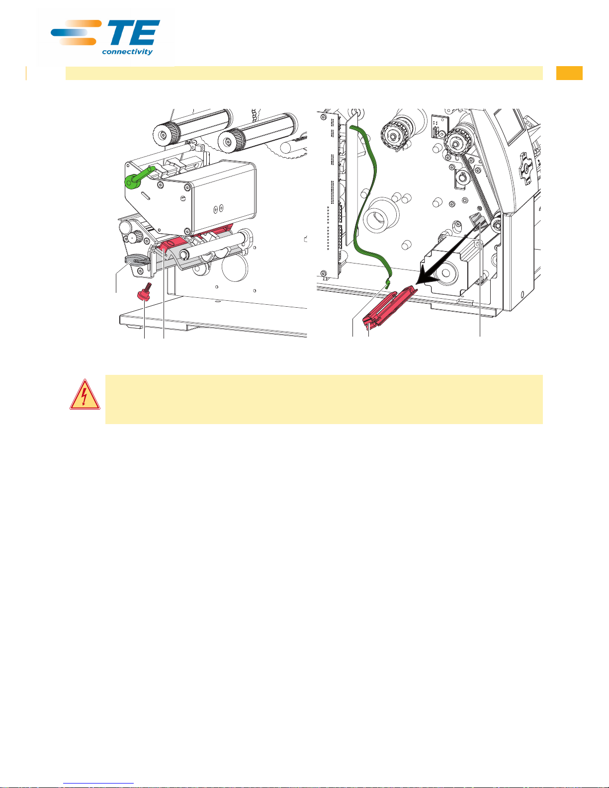
152
423
Fig. 1 Cleaning the label sensor Fig 2 Removing the label sensor
Danger!
Risk of death via electric shock!
X Before opening the housing cover, disconnect the device from the mains supply and wait at lease one
minute until the power supply unit has discharged.
1. Remove media from the printer.
2. Remove the Allen key (5) from its retainer.
3. Remove the rear cover of the printer.
4. Unscrew knurled thumb screw (1).
5. Unplug the cable (3) from the plug on the rear end of the label sensor (2).
6. Push the label sensor (2) so deep as possible into the guide prole toward the chassis.
7. Slide out the label sensor assembly (2) toward the back side cover.
8. Clean label sensor and sensor units (2) with brush or cotton swab soaked in pure alcohol.
9. Push label sensor back toward the print head side of printer so you can see the hole in the label sensor over the
long hole in the prole (guide).
10. Connect the cable (3) to the label sensor (2).
11. Attach knurled thumb screw (1).
12. Pull the label sensor (2) via knurled thumb screw (1) so far as possible toward cover side. This prevents the cable
(3) from being pinched when installing the rear cover.
13. Install the rear cover of the printer.
14. Adjust label sensor operators manual.
15. Insert the Allen key (5) into its retainer.
2 Cleaning
Page 8
8 8
3 Replacing Assembly Units
3.1 Tools
X Do not use any worn of damaged tools.
X Only use tools and testing devices that are suitable for the task at hand.
special tools:
• Test collar for transfer ribbon winder (5534199)
Standard tools:
• Phillips-head screwdriver, size 1
• Allen key 1,5 mm
• Screw driver Torx, size TX 20
• Snap ring pliers ZGG 0
• Cylindrical dynamometer (spring scale), 0 - 10 N
• Cylindrical dynamometer (spring scale), 0 - 25 N
• Jaw wrench 8 mm
3.2 Removing and Installing the Plastic Cover
!
Attention!
The plastic cover can be damaged via careless handling.
X Do not use force.
X Do not twist the plastic cover when removing it or pressing it on.
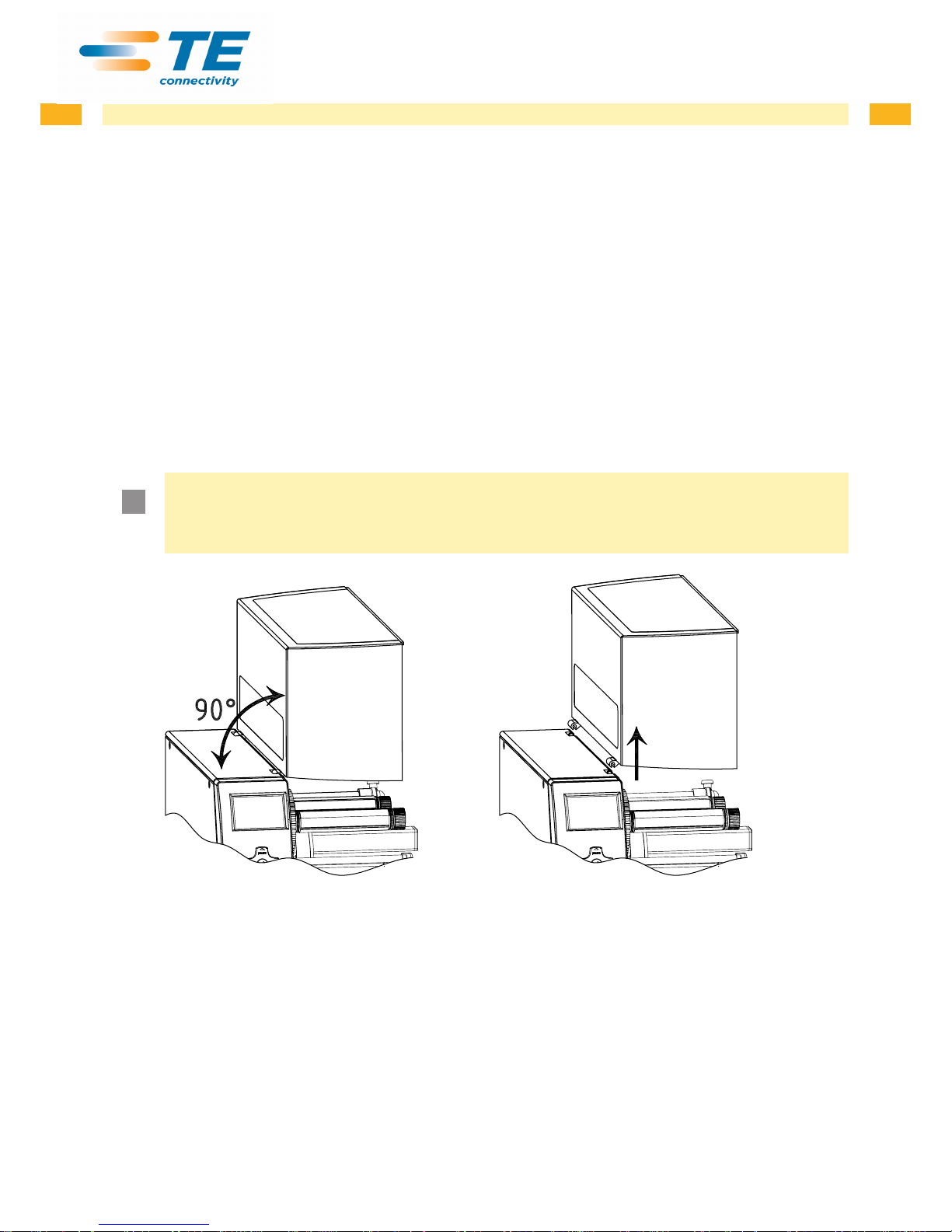
Fig. 3 Removing and installing the plastic cover
Removing the plastic cover :
1. Swivel the plastic cover up 90° and hold it in this position with both hands.
2. Carefully pull the hinges of the plastic cover out of the front mount and then the rear mount.
3. Put the plastic cover in a safe place.
Installing the plastic cover :
1. Place the hinges of the plastic cover onto the mounts with the open side downward.
2. First carefully press the rear hinge onto the respective mount and then do the same with the front hinge.
3. Swivel the plastic cover closed.
Page 9
9
3 Replacing Assembly Units
3.3 Replacing the Printhead
3.4 Replacing the Printhead
The printhead of the printer can be replaced without the need for ne adjustment. The printhead must be replaced if
worn or when switching to a printhead with higher or lower resolution. For better identication, the print heads have a
label stating the printer type and resolution.
1
2
3
4
6
7
4
6
5
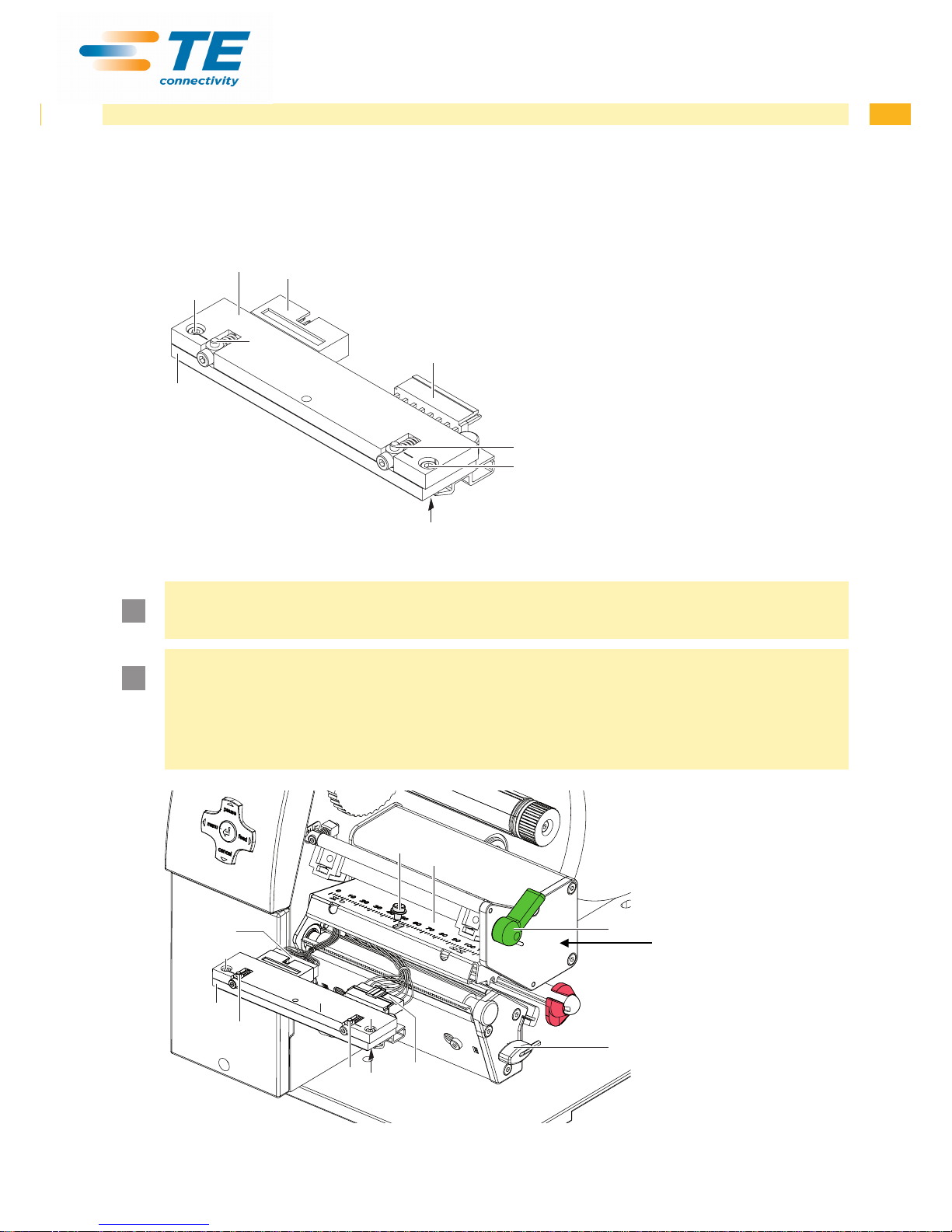
1 Head plate
2 Plug connection
3 Plug connection
4 Screw
5 Printing line
6 Pins
7 Printhead
Fig.4 Structure of the printhead
!
Attention!
The printhead (7) is adjusted on a head plate (1) and precisely aligned at the factory. Do not loosen the
screws (4) under any circumstances.
!
Attention!
The printhead can be damaged by static electricity discharges and impacts!
X Set up printer on a grounded, conductive surface.
X Ground your body, e.g. by wearing a grounded wristband.
X Do not touch contacts on the plug connections (2, 3).
X Do not touch printing line (5) with hard objects or your hands.
5
8
9
10
11
3
6
6
2
1
4
7
4
Fig. 5 Removing and installing the printhead
Note:
Location of item
11 has moved
on more recent
printer models
Page 10

10 10
3 Replacing Assembly Units
Removing the printhead
1. Turn lever (10) counterclockwise to lift the printhead.
2. Remove labels and transfer ribbon from the printer.
3. Remove Allen key (11) from its retainer.
4. Lightly keep printhead mounting bracket (9) on the print roller with one nger and screw out screw (8) with the
Allen key and remove it and the washer.
5. Swivel printhead mounting bracket (9) upward.
6. Remove printhead from the printhead mounting bracket (9) if necessary.
7. Loosen both plug connections (2, 3) on the printhead and set printhead down on a clean, soft surface.
Installing the printhead
1. Attach plug connections (2, 3).
2. Position printhead in printhead mounting bracket (9) in such a way that the pins (6) are secured in the corre-
sponding holes in the printhead mounting bracket (9).
3. Lightly keep printhead mounting bracket (9) on the print roller with one nger and check for correct positioning of
the printhead mounting bracket (9).
4. Screw in screw (8) with washer with the Allen key and tighten it.
5. Reload labels and transfer ribbon.
Page 11
11
3.5 Replacing the Slipping Clutches
The rewinder for the transfer ribbon and the internal rewinder are coupled to slipping clutches in the main drive. The
supply hub of the transfer ribbon is braked with a slipping clutch during printing.
Change the slipping clutch when it can no longer be set 4.1 on page 18. Removal and installation of the slipping
clutch is also required for replacement of a winder.
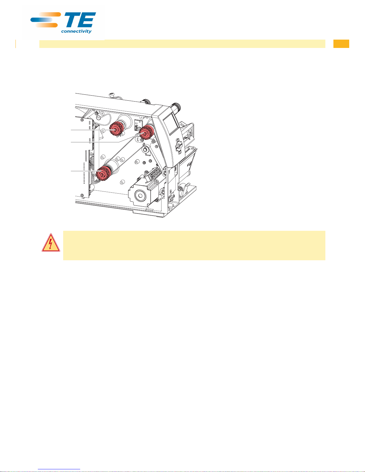
1
2
3
1 Transfer ribbon supply hub: brake
2 Transfer ribbon take up hub: coupling
3 Internal rewinder: coupling
Fig. 6 Slipping clutches
Danger!
Risk of death via electric shock!
X Before opening the housing cover, disconnect the device from the mains supply and wait at lease one
minute until the power supply unit has discharged.
Removing the slipping clutch
1. Unplug the printer from the electrical outlet.
2. Remove the rear cover of the printer.
3. Remove the snap ring (1).
4. Pull coupling or brake (2) from the winder axis (Item 5 in Fig. 7) or (Item 9 in Fig. 8).
5. Ensure that the pin (Item 11 in Fig. 8) remains on the winder axis when pulling the brake off. Reattach the pin to
the winder axis if it has been pulled off. The axis prole is shaped in such a way that the pin only ts on the winder
axis in one way.
3 Replacing Assembly Units
Page 12
12 12
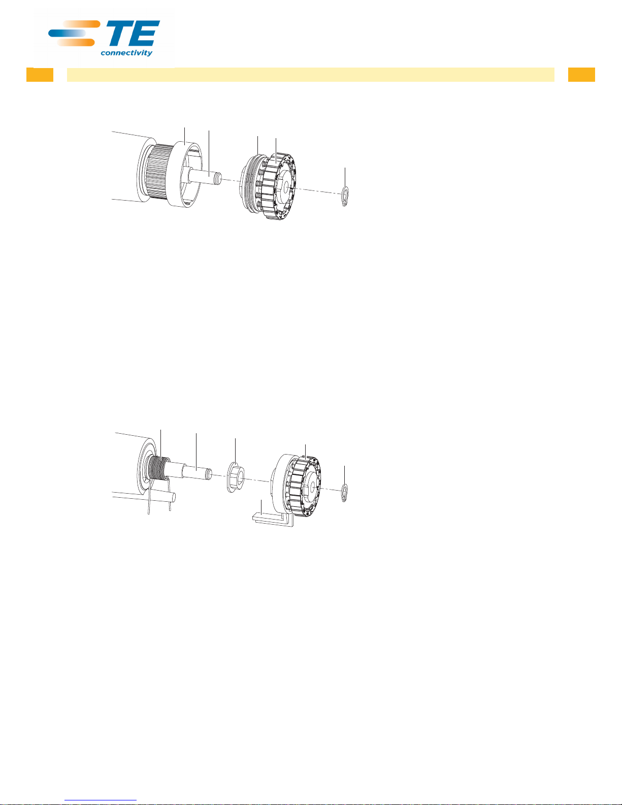
Installing the slipping clutch on the rewinders
8
7
6
5
4
4 Snap ring
5 Slipping clutch
6 Coupling disks
7 Winder axis
8 Collar of the belt wheel
Fig. 7
Slipping clutch on the rewinders
1. Slide coupling (5) onto the winder axis (7).
2. Align grooves in the coupling disks (6) with the guides in the collar of the belt wheel (8).
3. Slide coupling further until it stops.
4. Secure the snap ring (4).
5. Adjust the coupling 4.1 on page 19.
6. Pull the label sensor toward the cover side as far as possible and install the rear cover of the printer.
Installing the brake on the transfer ribbon supply hub
12
7
11
9
4
10
4 Snap ring
7 Winder axis
9 Brake
10 Lever
11 Pin
12 Spring
Fig. 8 Brake on transfer ribbon supply hub
1. Slide the brake (9) onto the winder axis (7) in such a way that it ts on the hexagonal prole of the pin (11).
2. Ensure that the lever (10) grasps between the two ends of the spring (12).
3. Secure the snap ring (4).
4. Adjust the coupling 4.1 on page 19.
5. Pull the label sensor toward the cover side as far as possible and install the rear cover of the printer.
3 Replacing Assembly Units
Page 13
13
3.6 Replacing the Label Sensor
i
Notice!
Contamination of the label sensor can also cause malfunctions. Before replacing the label sensor, check
whether it is soiled and clean it if necessary..
Danger!
Risk of death via electric shock!
X Before opening the housing cover, disconnect the device from the mains supply and wait at lease one
minute until the power supply unit has discharged.
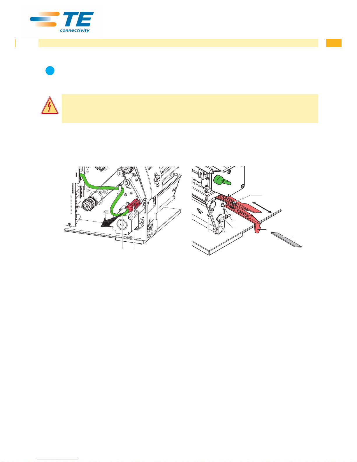
3.6.1 Replacing Standard Label Sensor
2 1
3
4
6
5a
1
5b
5c
7
Fig. 9 Replacing the standard label sensor
Removing the label sensor
1. Remove media from the printer.
2. Remove the Allen key (6) from its retainer.
3. Remove the rear cover of the printer.
4. Slide the label sensor assembly onto the tab (4) toward the rear cover until it stops.
5. Unplug the cable (2) from the plug on the rear end of the label sensor (1).
6. Unscrew the screws (5) with an Allen key and remove the side plate (7).
7. Pull out the label sensor (1) via the tab (4) toward the cover side.
Installing the label sensor
1. Insert the label sensor (1) into the guide from the cover side and slide it onto the tab (5) toward the rear cover until
it stops.
2. Remount the side plate (7) with the screws (5) by tightening the screws in order, i.e. a, b then c.
3. Connect the cable (2) to the label sensor (1).
4. Pull the label sensor (1) via the tab (4) as far as possible toward the cover side.
This prevents the cable (2) from being pinched when installing the rear cover.
5. Install the rear cover of the printer.
6. Insert the Allen key (6) into its retainer.
7. Adjust the label sensor Conguration Manual.
3 Replacing Assembly Units
Page 14
14 14
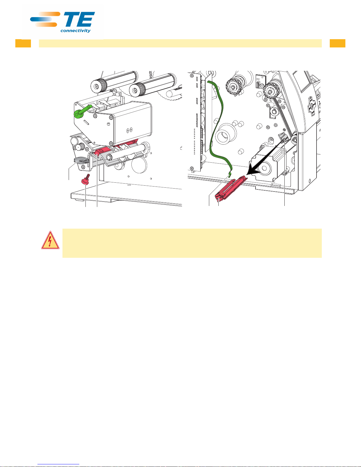
3.6.2 Replacing Label Sensor
152
423
Fig. 10 Replacing the label sensor
Danger!
Risk of death via electric shock!
X Before opening the housing cover, disconnect the device from the mains supply and wait at lease one
minute until the power supply unit has discharged.
Removing the label sensor
1. Remove the Allen key (5) from its retainer.
2. Remove the rear cover of the printer.
3. Unscrew knurled thumb screw (1).
4. Unplug the cable (3) from the plug on the rear end of the label sensor (2).
5. Push the label sensor (2) so deep as possible into the guide prole toward the chassis.
6. Slide out the label sensor assembly (2) toward the back side cover.
Installing the label sensor
1. Push label sensor back toward the print head side of printer so you can see the hole in the label sensor over the
long hole in the prole (guide).
2. Connect the cable (3) to the label sensor (2).
3. Attach knurled thumb screw (1).
4. Pull the label sensor (2) via knurled thumb screw (1) so far as possible toward cover side. This prevents the cable
(3) from being pinched when installing the rear cover.
5. Install the rear cover of the printer.
6. Insert the Allen key (5) into its retainer.
7. Adjust label sensor.
8. Adjust the label sensor.
3 Replacing Assembly Units
Page 15
15
3.7 Replacing the PCB CPU
Danger!
Risk of death via electric shock!
X Before opening the housing cover, disconnect the device from the mains supply and wait at lease one
minute until the power supply unit has discharged.
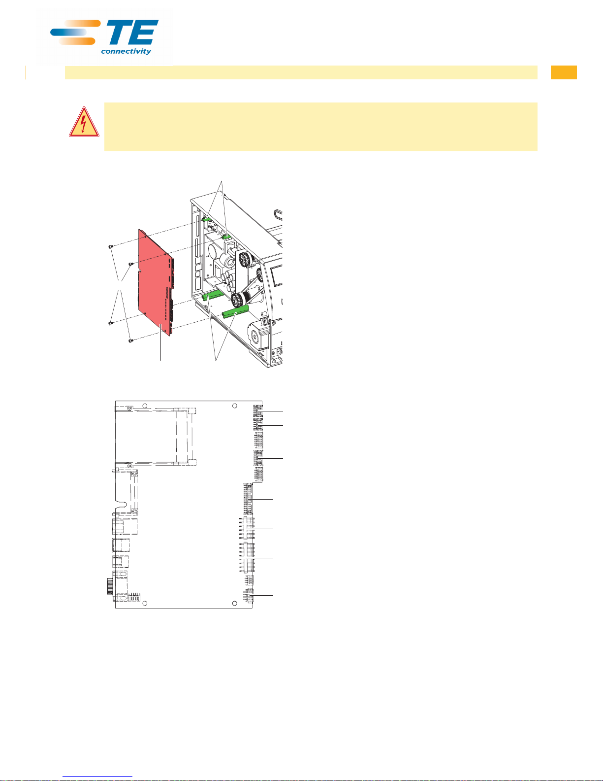
3
12
1
Removing the PCB CPU
1. If possible, save the printer conguration to a CompactFlash card.
2. Unplug the printer from the electrical outlet.
3. Detach all interface cables from the back of the printer.
4. Remove all memory cards from the slots.
5. Screw off the rear cover.
6. Unplug all side plug connections from the PCB CPU (2).
7. Remove the four xing screws (3) from the PCB CPU.
8. Remove the PCB CPU.
Fig. 11 Removing the PCB CPU
4
5
6
7
8
9
10
Fig. 12 Used connectors on the PCB CPU
4 Control panel
5 Peripheral port
6 Sensors
7 Printhead signals
8 Printhead power supply
9 Power supply unit
10 Stepper motor
Installing the PCB CPU
1. Place PCB CPU (2) onto the retainers (1).
2. Secure the PCB with four screws (3).
3. Insert all plug connections on the PCB.
4. Pull the label sensor toward the cover side as far as
possible and install the rear cover of the printer.
5. Restore all interface connections on the back of the
printer.
6. Connect the power cable at the rear of the printer.
7. Update the rmware if necessary.
8. Adjust the label sensor.
9. Load the printer conguration from the memory card if
possible. Otherwise, set the printer conguration via the
control panel.
3 Replacing Assembly Units
Page 16
16 16
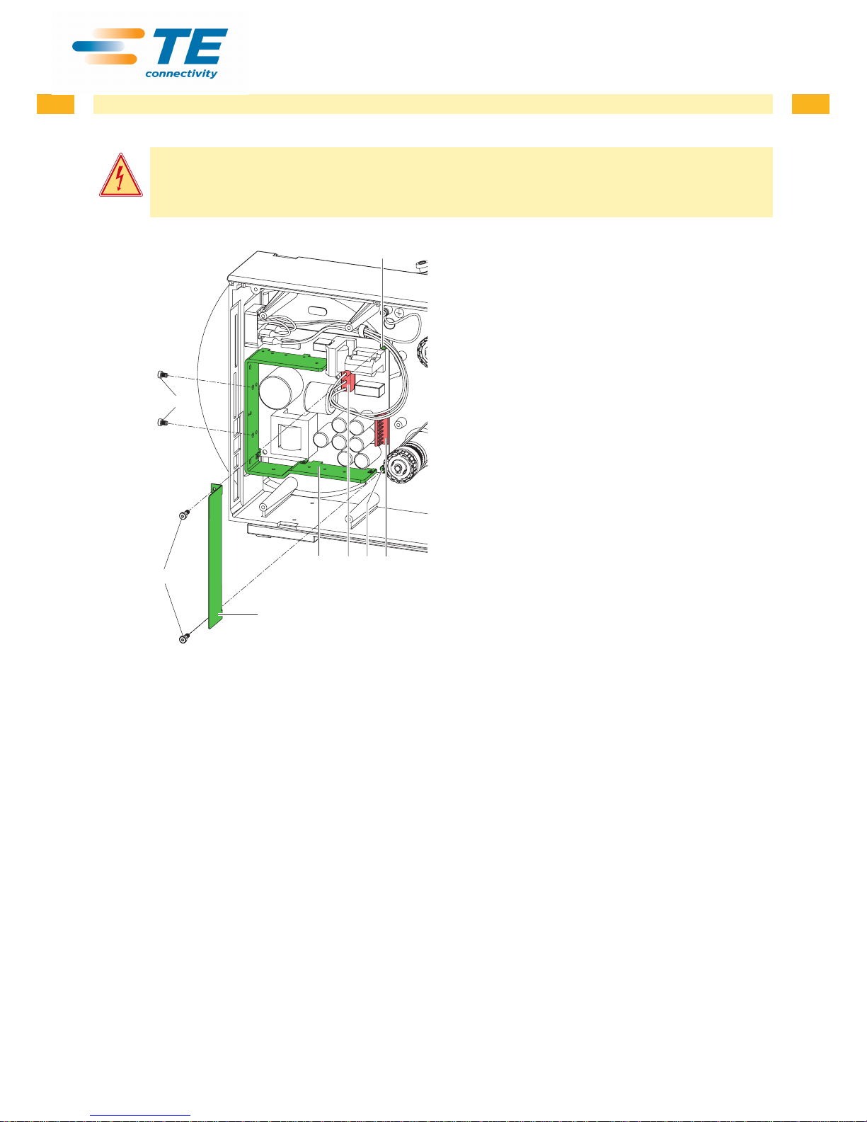
3.8 Replacing the Power Supply Unit
Danger!
Risk of death via electric shock!
X Before opening the housing cover, disconnect the device from the mains supply and wait at lease one
minute until the power supply unit has discharged.
123
2
6
7
5
4
Removing the power supply unit
1. Unplug the printer from the electrical outlet.
2. Remove the PCB CPU 3.7 on page 15.
3. Remove the two screws (6) of the cover plate (5).
4. Remove the cover plate (5).
5. Unplug the plug at the power supply unit input (3).
6. Unplug the plug at the power supply unit output (1).
7. Remove the two screws on the back of the printer (7).
8. Hold the power supply unit rmly at the metal bracket (4)
and remove the two screws (2).
9. Remove the power supply unit.
Installing the power supply unit
1. Insert the power supply unit and secure the PCB with two
screws (2).
2. Secure the metal bracket (4) of the power supply unit to
the back of the printer with two screws (7).
3. Connect the power supply unit cable to the power supply
output (1).
4. Insert the power input cable (3).
5. Insert the cover plate (5) and secure it with the two
screws (6).
6. Install the PCB CPU.
Fig. 13 Replacing the power supply unit
3 Replacing Assembly Units
Page 17

17
4 Adjustments
4.1 Measuring and Adjusting the Winding Torques
The rewinder for the transfer ribbon and the internal rewinder are coupled to slipping clutches in the main drive. The
supply hub of the transfer ribbon is braked with a slipping clutch during printing.
The correct setting of the torques of these slipping clutches is necessary for:
• precise conveyance of the transfer ribbon during label transport
• the prevention of wrinkles in the feed path of the transfer ribbon
• sufciently tight peel-off tension of the liner and thus easy peeling off of labels in peel-off mode
• a sufciently tightened label strip
The winding axes of the rewinder are not actively driven by the belts during label backfeed, but rather solely by the
pull of the print roller. The torque required to disengage the rewinder from the belt drive is implemented via a brake
in the winding reel, which works in both directions. The measured clockwise torque is the sum of the coupling torque
and the torque of the brake. Only the torque of the brake is measured when the winding axis is rotating counterclockwise. For this reason, measurement of the torques at the rewinders are required in both directions.
The method of measurement differs for the various types of slipping clutches:
• measurement of the winding torques at the transfer ribbon take up and supply hub page 18.
• measurement of the winding torque at the internal rewinder page 19.
If the winding torque differs from the set value, it must be adjusted. The procedures for adjusting the winding torques
of the transfer ribbon winders and the internal rewinder are identical 4.1.2 on page 20.
4.1.1 Measuring the Winding Torques
Transfer ribbon take up and supply hub
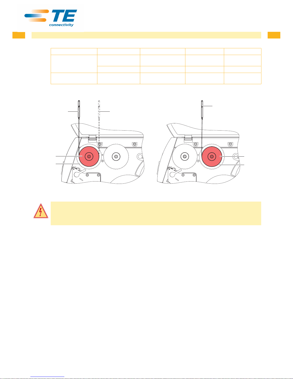
Measurement of the winding torque at the transfer ribbon take up and supply hub occurs by determining the pulling
forces on a test collar attached to the winder.
The physical relation between the torque and the pulling force is:
F= M / r
F: Pulling force [N],
M: Winding torque [Ncm],
r: Radius of the test collar (30 mm)
Page 18
18 18
4 Adjustments
The set values for the winding torque and the resulting pulling force at the test collar are:
Slipping clutch on Direction of rotation Printer Winding torque M Pulling force F
Ribbon take up hub clockwise TE3124
TE3112
13.5 - 14.4 Ncm
13.5 - 14.4 Ncm
4.3 - 4.8 N
4.3 - 4.8 N
counterclockwise all 2.1 - 3.0 Ncm 0.7 - 1.0 N
Ribbon supply hub any TE3124
TE3112
3.6 - 4.5 Ncm
3.6 - 4.5 Ncm
1.2 - 1.5 N
1.2 - 1.5 N
Table 1 Winding torques at the transfer ribbon hubs
1
3
4
4
3
1 2
Fig. 14 Measuring the winding torque at the transfer ribbon take up hub (left) and supply hub (right)
Danger!
Risk of death via electric shock!
X Before opening the housing cover, disconnect the device from the mains supply and wait at lease one
minute until the power supply unit has discharged.
1. Unplug the printer from the electrical outlet.
2. Remove the rear cover.
3. Remove the transfer ribbon from the printer.
4. Attach the test collar (3) to the winder (4).
5. Turn the knurled nut counterclockwise to clamp the test collar.
6. Wind the cord attached to the test collar around the test collar several times.
7. Secure spring scale [10 N] (1) at the end of the cord.
8. Move the spring scale upward vertically until the winder begins turning.
9. If the drive belt at the rewinder is also moving, hold it in place during the measurement. Otherwise, the
measurement is not accurate.
10. Allow the cord to unwind from the test collar at least one full turn and read the pulling force F on the spring scale
at the same time.
11. Determine the pulling force at the transfer ribbon take up hub in the same manner, except in the opposite rotation
direction (2).
12. If the winding torque differs from the set value, it must be adjusted 4.1.2 on page 20.
Page 19
19
4 Adjustments
Internal rewinder
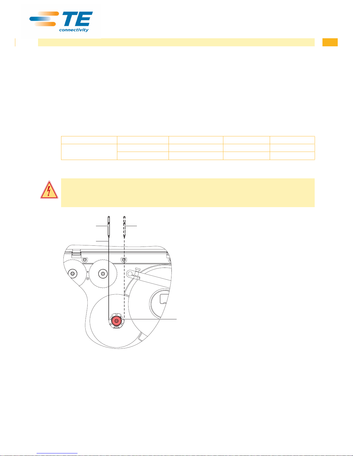
Measurement of the winding torque at the internal rewinder occurs by determining the pulling forces with a cord
wrapped around the rewinder.
The physical relation between the torque and the pulling force is:
F= M / r
F: Pulling force [N],
M: Winding torque [Ncm],
r: Radius of the internal rewinder (20 mm)
The set values for the winding torque and the resulting pulling force at the test collar are:
Slipping clutch on Direction of rotation Printer Winding torque M Pulling force F
Internal rewinder clockwise TE3124/TE3112 28 - 32 Ncm 14 - 16 N
counterclockwise TE3124/TE3112 8 - 12 Ncm 4 - 6 N
Table 2 Winding torques at the internal rewinder
Danger!
Risk of death via electric shock!
X Before opening the housing cover, disconnect the device from the mains supply and wait at lease one
minute until the power supply unit has discharged.
3
1
2
4
1. Unplug the printer from the electrical outlet.
2. Remove the rear cover.
3. Remove the label media from the printer.
4. Push the cord (2) under a bracket of the internal
rewinder (3) and wind it around the rewinder.
5. Secure spring scale [25 N] (1) at the end of the cord.
6. Move the spring scale (1) upward vertically until the
winder begins turning.
7. If the drive belt is also moving, hold it in place during
the measurement. Otherwise, the measurement is
not accurate.
8. Allow the cord to unwind from the test collar at least
one full turn and read the pulling force F on the
spring scale at the same time.
9. Determine the pulling force in the same manner,
except in the opposite rotation direction (4).
10. If the winding torque differs from the setpoint, it must
be adjusted 4.1.2 on page 20.
Fig. 15 Measuring the winding torque at the internal rewinder
Page 20
20 20
4 Adjustments
4.1.2 Adjusting the Winding Torques
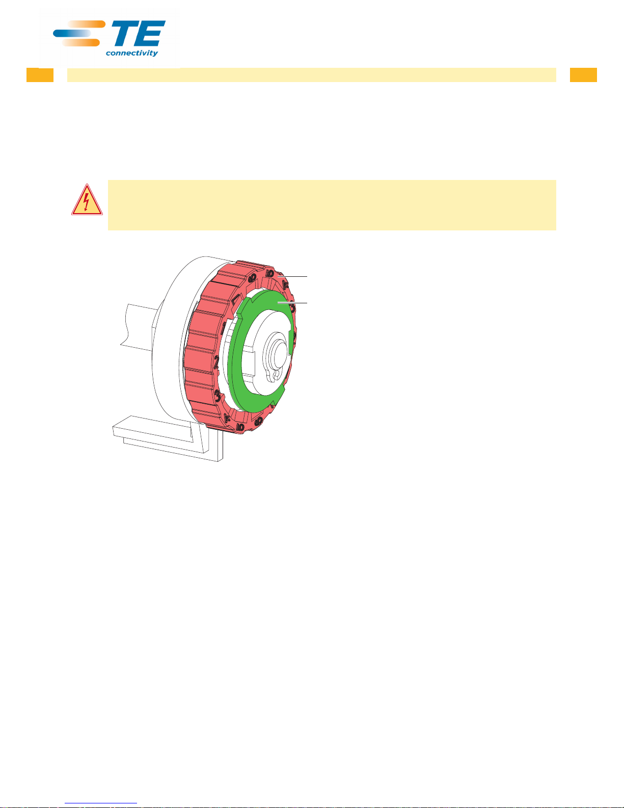
The winding torque of a winder can be changed at the knurled ring of the respective slipping clutch. The numbers on
the knurled ring stand for the value of the winding torque:
• 1: Lowest winding torque
• 7: Highest winding torque
The current value is indicated by the number located at the positions of the two locking tabs.
Danger!
Risk of death via electric shock!
X Before opening the housing cover, disconnect the device from the mains supply and wait at lease one
minute until the power supply unit has discharged.
2
1
1. Unplug the printer from the electrical outlet.
2. Remove the rear cover.
3. Press the knurled ring (1) of the slipping clutch
toward the housing wall.
The lock (2) of the knurled ring is released.
4. Turn the knurled ring while pushing it and release it
in the desired position.
5. Ensure that the tabs of the lock are located
completely in the grooves of the setting value.
6. Measure the winding torque again and compare it to
the set value.
Transfer ribbon hubs page 18
Internal rewinder page 19
7. Repeat the adjustment until the measured winding
torque is within the tolerance range.
8. Pull the label sensor toward the cover side as far as
possible and install the rear cover of the printer.
Fig. 16 Adjusting the winding torque
Page 21
21
4 Adjustments
4.2 Adjusting the Printing Mechanism
Major adjustment of the printing mechanism beyond format-based settings is only required if the printhead assembly
has been removed or parts in this area have been replaced. Excluded from this is the replacement of the printhead,
after which readjustment is generally not required.
The following print quality imperfections may indicate maladjustment of the printing mechanism:
• Print image too light
• Print image is spotty
• Print image lighter on one side
• Horizontal lines not parallel to the horizontal label edges
• Clear lateral drift of the transfer ribbon
i
Notice!
Print image errors can also arise from wrinkling of the transfer ribbon. This is why you should check the
transfer ribbon feed path and the head locking system for correct adjustment before making adjustments to
the printing mechanism Operator's Manual.
Adjustment of the printing mechanism comprises the following procedures in the order specied:
1. Prepare the label printer for adjustment 4.2.1 on page 21.
2. Adjust the position of the printhead 4.2.2 on page 22.
3. Adjust the printhead pressure 4.2.3 on page 23.
4. Adjust the transfer ribbon feed path 4.2.4 on page 24.
5. Perform a nal test 4.2.5 on page 24.
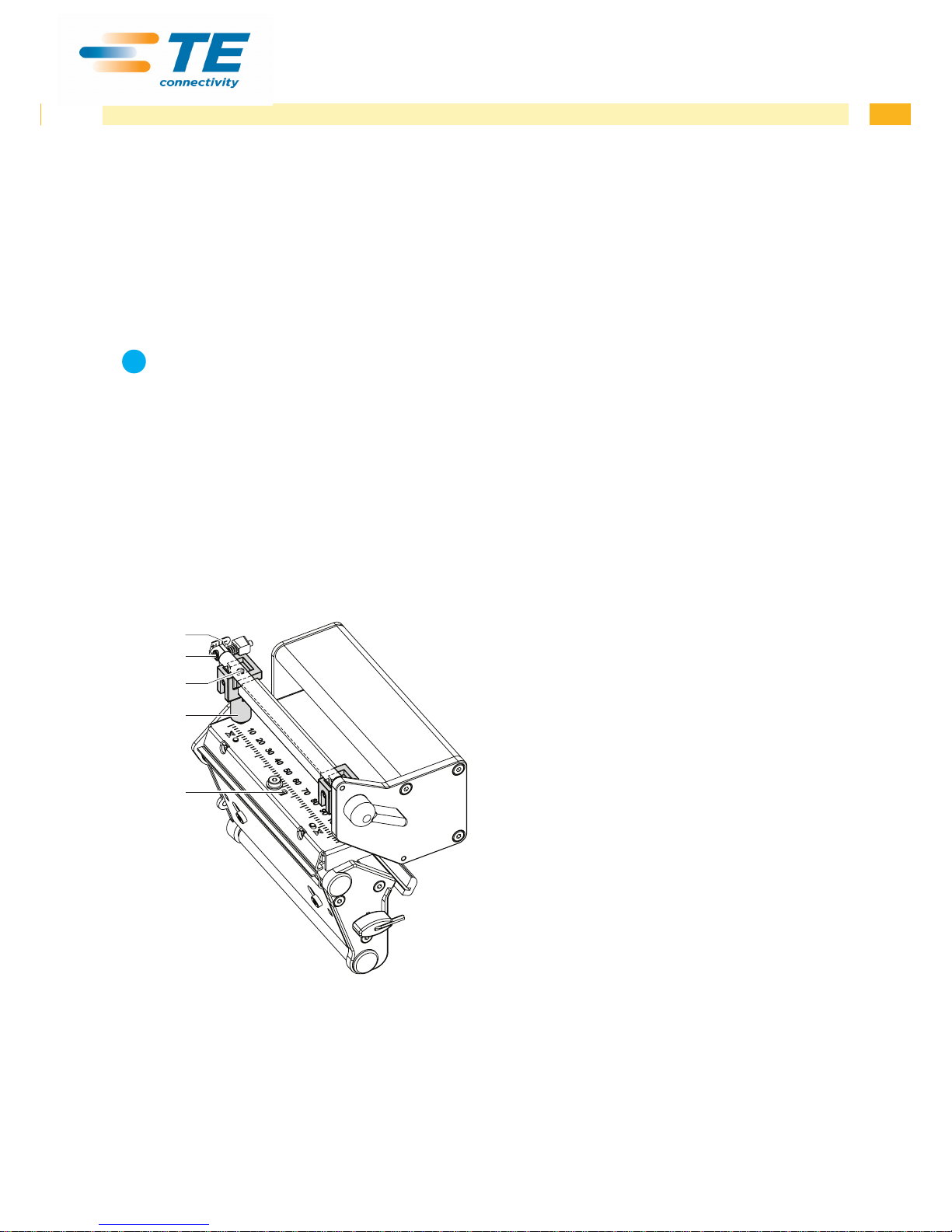
4.2.1 Preparing the Printer for Adjustment
5
4
1
2
3
1. Load labels and transfer ribbon which extend across
the entire printing width.
2. In the printer conguration, set the Heat level
parameter to -5 and the Print speed parameter to
100 mm/s..
3. Move the transfer ribbon deection to the central
position (5) with the screw (4).
4. Position the plungers (2) in such a way that the
adjustment screws are accessible through the holes
(3) of the square axis.
5. Loosen the screw (1) for the printhead bowing with
an Allen key (1.5 mm) and turn it counterclockwise
until turning becomes perceptibly easier. This should
occur after a maximum of a half a rotation.
6. Continue with the adjustment of the printhead
position 4.2.2 on page 22.
Fig. 17 Preparing the printer for adjustment
Page 22
22 22
4 Adjustments
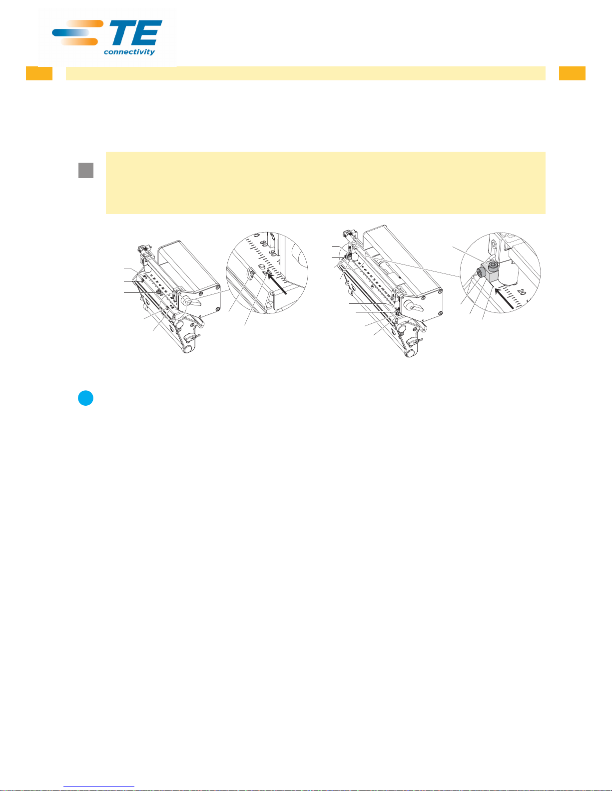
4.2.2 Adjusting the Printhead Position
In order to achieve the best possible print image the following printhead settings are necessary:
• Align the heating line with the highest point of the print roller. Density of the print image is the greatest at this
point.
• Set the parallelism of horizontal lines with the edge of the label.
!
Attention!
The printhead assembly can be damaged.
Attempting to adjust the printhead when the xing screws (3) are tight can lead to defects at the printhead
assembly.
X Always loosen the xing screws (3) before adjusting the printhead.
1a
2a
3
2b
1b
1b
2b
2b
2a
3
3
5a
4a
4b
5b
2a
5a
4a
3
Fig. 18 Adjusting the printhead position
i
Notice!
X Open and close the printhead lock after each step of the adjustment.
1. Check the alignment of the printhead in the adjustment windows (1).
2. If the printhead is not aligned properly, loosen the screw (3) about one quarter turn.
3. If the printhead is not aligned properly, use the screws (2) to align the lines on the printhead with the tips of the
grooves.
- Screw (2a) effects the inner half of the printhead, and screw (2b) the outer half.
- Turning clockwise moves the printhead forward.
4. Create print samples with the test function Test grid or a similar print pattern.
5. If the horizontal lines in the test grid are not parallel with the label edges, adjust the parallelism with the screws
(2).
6. Set the best possible image quality by maintaining parallelism via turning the screws (2a) and (2b) in an alternating fashion.
Differences in the density between the two sides are still permissible.
7. Tighten the screws (3).
8. When the parallelism of the printhead is set, continue with the adjustment of the printhead pressure
4.2.3 on page 23.
Page 23
23
4 Adjustments
4.2.3 Adjusting the Printhead Pressure
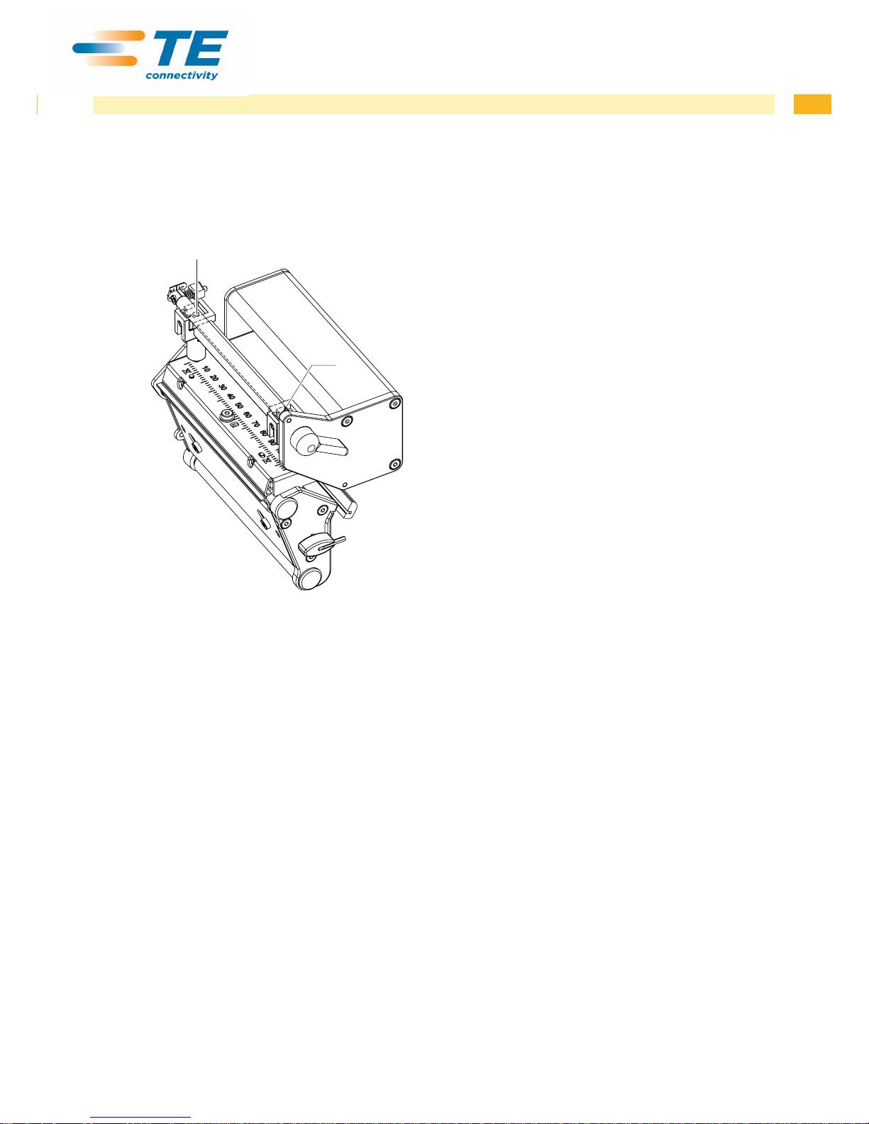
The printhead pressure can be changed with the screws (1a) and (1b) at the inside and outside of the printhead.
Increasing the head contact pressure leads to an improvement of the print image density on the corresponding side
and to a shifting of the ribbon feed path in the corresponding direction.
1a
1b
Fig. 19 Adjusting the printhead pressure
1. Turn the adjustment screws (1) counterclockwise until turning becomes perceptibly easy.
2. The heat level is to be reduced in the printer conguration until the print image is only barely recognizable. Under
these conditions, inaccuracies become clearly visible during adjustment.
3. Create print samples with the test function Test grid or a similar print pattern.
4. Adjust the adjustment screw (1a or 1b) clockwise in small increments on the side with the weaker print image until
the print image is even across the entire width. It may happen that you must turn the adjustment screws in an
alternating fashion, resulting in a print image which is too light overall.
5. For TE3124 /TE3112 printer move the plunger to the printer standard position for the media being printed
operator's manual and repeat the test print. Possibly rerun procedure and adjust again.
6. When the print image is set evenly, continue with setting of the transfer ribbon feed path 4.2.4 on page 24.
Page 24
24 24
4 Adjustments
4.2.4 Adjusting the Transfer Ribbon Feed Path
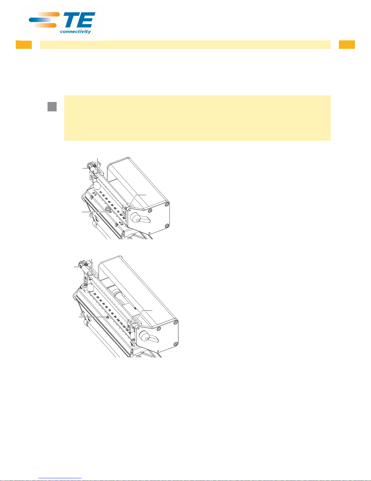
You can adjust the transfer ribbon feed path by changing the head contact pressure and adjusting the transfer ribbon
deection. Increasing the head contact pressure with the screws (3a) and (3b) shifts the ribbon feed path in the
corresponding direction. The skew of the transfer ribbon deection is used to suppress wrinkles in the transfer ribbon
feed path. Wrinkles which cannot be remedied with the skew of the transfer ribbon deection can be suppressed by
bowing the printhead.
!
Attention!
The printhead assembly can be damaged when bowing the printhead.
Turning the adjustment screw (1) too hard can cause damage to the printhead assembly.
X As soon as you perceive clear resistance when turning the adjustment screw (1), you may only continue
turning the screw in very small increments, but no more than one eighth of a turn.
X Only turn the adjustment screw (1) as far as is absolutely necessary.
2
1
3a
3b
3a
2
1
3b
1. Check the transfer ribbon feed path.
The wound up ribbon should be the same distance
from the disk of the winder as the supply roll is from
the disk of the supply hub.
2. If the ribbon runs inward or outward, turn the corresponding screw (3a) or (3b) clockwise in small
increments.
3. Wait until the ribbon feed path has stabilized after
each step of the adjustment.
4. Check the ribbon feed path for wrinkles.
5. If wrinkles arise on the inside, turn the screw (2)
counterclockwise.
6. If wrinkles arise on the outside, turn the screw (2)
clockwise.
7. If the wrinkles cannot be remedied (e.g. wrinkles in
the center), turn the adjustment screw (1) clockwise
with extreme care using an Allen key (1.5 mm) and
observe the ribbon feed path.
When the adjustment screw (1) is tightened, the
printhead is bent downward slightly in the center. It is
possible that a slight lightening at the edge areas of
the print image could occur here.
8. If bowing is not necessary, turn the screw (2)
clockwise until the screw is just barely clamping.
9. When the transfer ribbon feed path is set, continue
with the nal test.
Fig. 20 Adjusting the transfer ribbon feed path
4.2.5 Final Test
X Reset the Heat level to +5 in the printer conguration
X Recheck the setting with the test function Test grid or a similar print pattern.
When using standard media, the test printout must show lines with sharp contours and black areas without any parts
missing.
Page 25
25
4 Adjustments
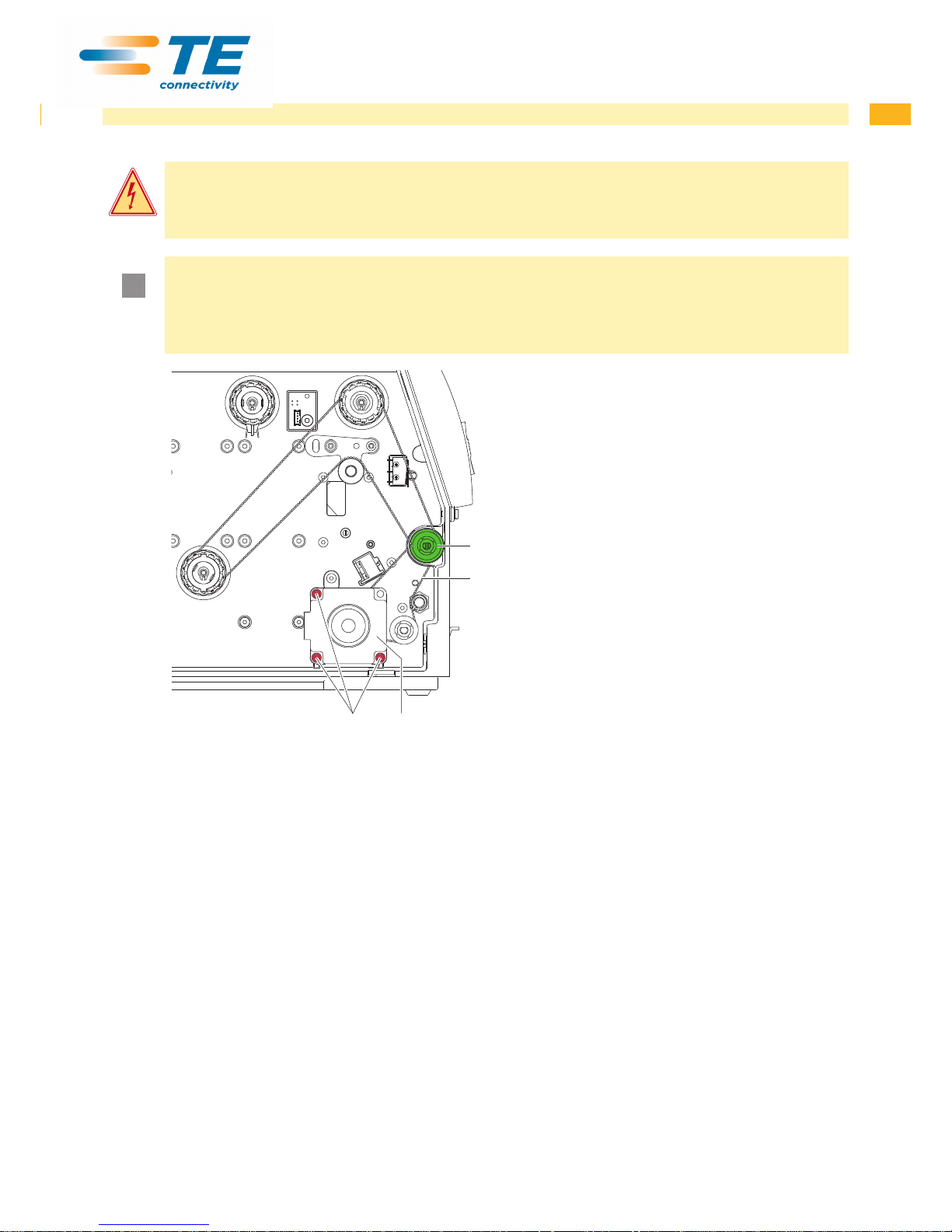
4.3 Adjusting the Belt Tension at the Main Drive Motor
Danger!
Risk of death via electric shock!
X Before opening the housing cover, disconnect the device from the mains supply and wait at lease one
minute until the power supply unit has discharged.
!
Attention!
The toothed belt could be damaged if adjustment is carried out improperly.
Improper adjustment or insufcient tension of the toothed belt could cause it to rub against the label
sensor during printing, which would damage the belt.
X Tension the toothed belt in such a way that it cannot rub against the label sensor.
34
2
1
1. Unplug the printer from the electrical outlet.
2. Remove the rear cover.
3. Loosen the three xing screws (4) of the main drive
motor (3).
4. Swivel the main drive motor (3) in such a way that
the toothed belt (2) is tensioned tightly between the
motor and the print roller (1).
5. Tighten the xing screws (4) in this position of the
motor.
6. Pull the label sensor toward the cover side as far as
possible and install the rear cover of the printer.
Fig. 21 Adjusting the belt tension
Page 26
26 26
4 Adjustments
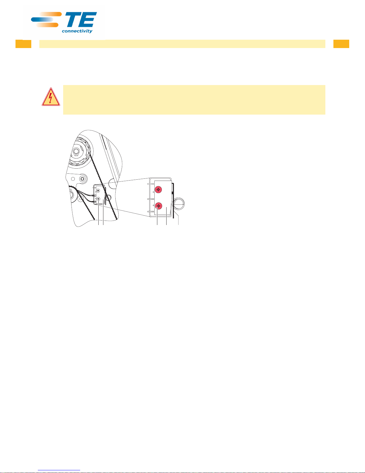
4.4 Adjusting the Head Switch
The head switch prevents printing from occurring when the printhead is open.
Adjust the head switch if the error message Head open appears in the display even though the printhead is locked.
Danger!
Risk of death via electric shock!
X Before opening the housing cover, disconnect the device from the mains supply and wait at lease one
minute until the power supply unit has discharged.
12323
1. Unplug the printer from the electrical outlet.
2. Remove the rear cover.
3. Lock printhead.
4. Slightly loosen the xing screws (3) of the head
switch (2).
5. Move the head switch housing and switching lever
(1) to a parallel position (see magnied cutout).
6. Screw down the head switch in this position.
7. Check whether the Head open message is still
shown in the display. If this is the case, replace the
switch with cable.
8. Pull the label sensor toward the cover side as far as
possible and install the rear cover of the printer.
Fig. 22 Adjusting the head switch
Page 27

27
5 Troubleshooting and Error Correction
5.1 Failure of Device Functions
Functional error Possible remedy
Medium is not transported Check electrical connections between PCB CPU and motor
Check drive mechanism
Replace the PCB CPU
Replace the motor
No print image with medium
transport
Check plug connections at the printhead
Examine printhead cable for damage and replace if necessary
Replace the printhead
Replace the PCB CPU
Display and navigator pad are
not functioning
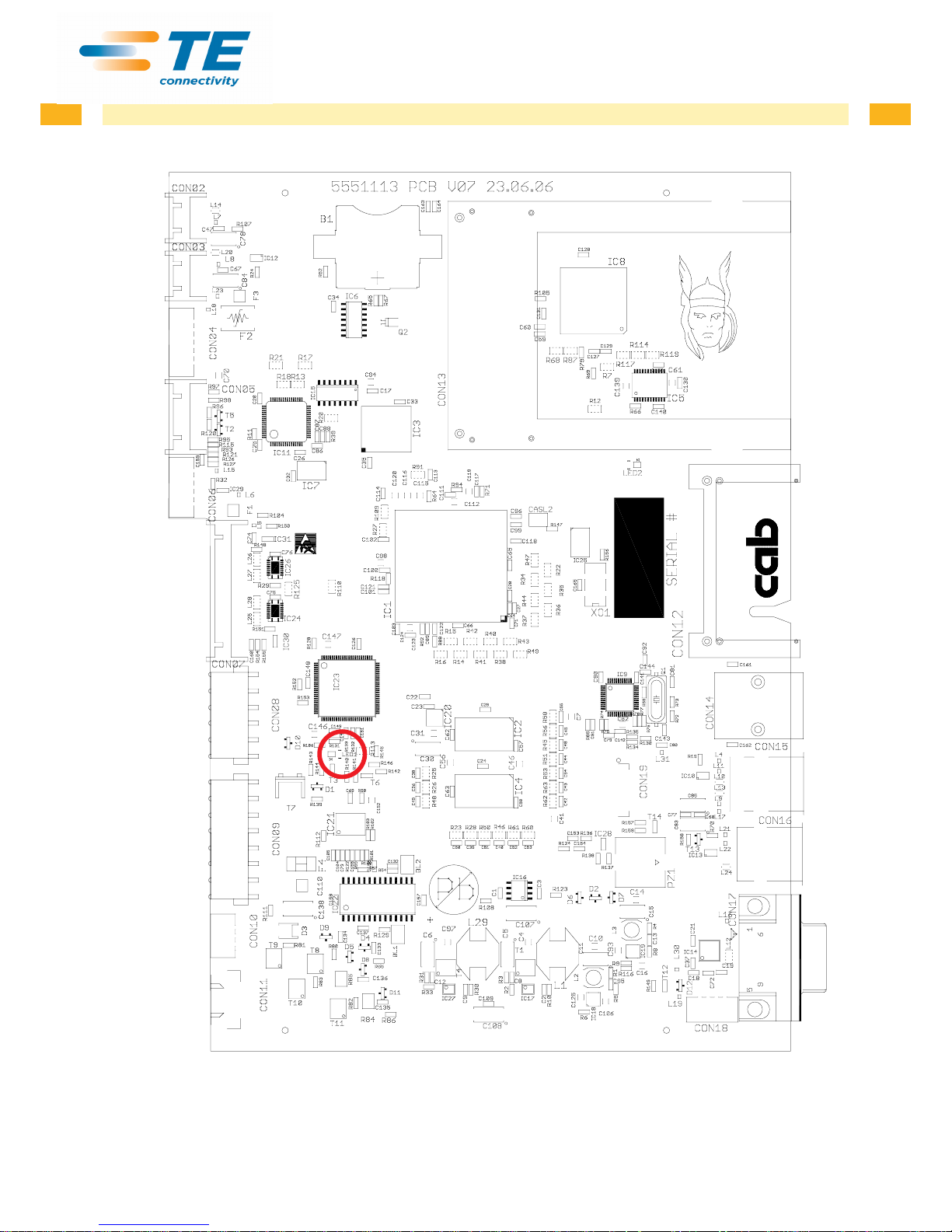
Check whether LED1 (green) is illuminating on the PCB CPU
Fig. 24 on page 30:
• LED1 is not illuminating: The power supply unit or CPU PCB is defective.
Replace PCB CPU or Power supply unit.
• LED1 ashes: Firmware update unsuccessful.
Reload the rmware.
Check cable connection between PCB CPU and control panel
Check whether the correct voltages are active at the 3,3 V and 5 V measurement
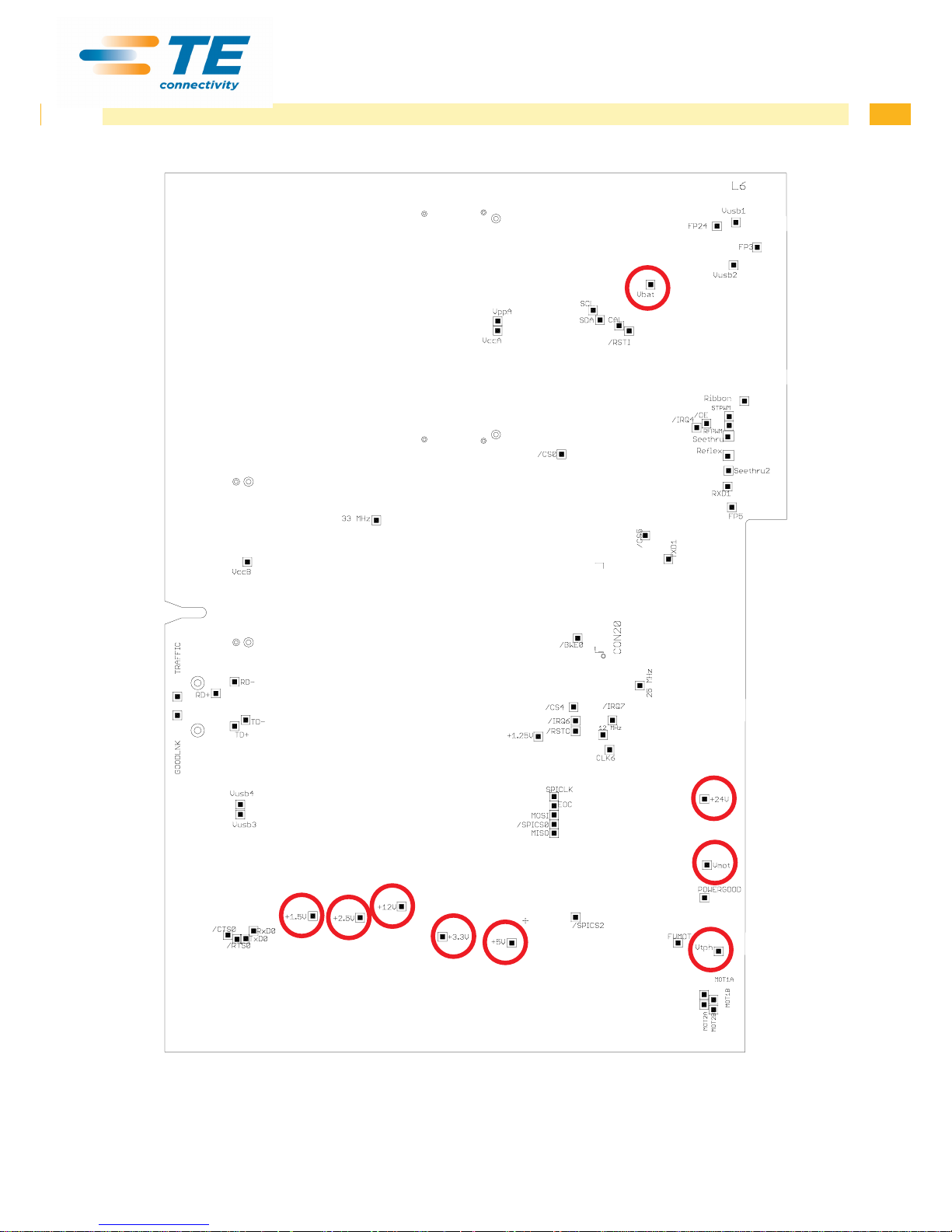
points on the PCB CPU Fig. 25 on page 31
• No voltage at either measurement point: The power supply unit may be
defective. Replace the power supply unit
• No voltage at one measurement point: The PCB CPU may be defective.
Replace the PCB CPU.
Replace LCD Display cpl.
Replace PCB Navi Button assem.
The display is not functioning,
but the navigator pad is
functioning
Replace LCD Display cpl.
The navigator pad is not
functioning, but the display is
functioning
Check the cable connection between LCD Display cpl. and PCB Navi Button
assem. and replace if necessary
Replace PCB Navi Button assem.
Replace LCD Display cpl.
Communication via an interface
is not functioning
Check whether the interface congurations of the printer and computer match
For an Ethernet connection, check the validity of the IP address and the subnet
mask
Check the interface cable and replace it if necessary
If all functionality of the interface has been lost, replace the PCB CPU
A peripheral device is not
functioning
Check whether the peripheral device is activated via programming
Check the USB cable of the peripheral device and replace it if necessary
Check the peripheral device
Replace the PCB CPU
Table 3 Failure of device functions
Page 28

28 28
5 Troubleshooting and Error Correction
5.2 Hardware Faults
Error message Cause Fault recovery
ADC malfunction
Fault on the PCB CPU Replace the PCB CPU
FPGA malfunction
Fault on the PCB CPU Replace the PCB CPU
Invalid setup
Fault on the PCB CPU Replace the PCB CPU
Voltage error
V
BAT
Voltage of the battery on the
PCB CPU is too low
Replace the PCB CPU
V
MOT
Motor voltage is too low Check motor voltage at the
measurement point V
mot
Fig. 25 on page 31:
• Voltage too low:
Replace the power supply unit
• Voltage is correct:
Replace the PCB CPU
24 V
24 V too low Check voltage at measurement point
+24V
Fig. 25 on page 31:
• Voltage too low:
Replace the power supply unit
• Voltage is correct:
Replace the PCB CPU
24 V ext.
24 V at peripheral connection
too low
Disconnect peripheral device
• Fault still exists:
Replace the PCB CPU
• Fault remedied:
Repair or replace peripheral
device
5 V ext.
5 V at Centronics connection
too low
Interface converter with
excessive power consumption
may be connected
Disconnect interface converter
• Fault still exists:
Replace the PCB CPU
• Fault remedied:
Replace interface converter
Table 4 Hardware faults
Page 29
29
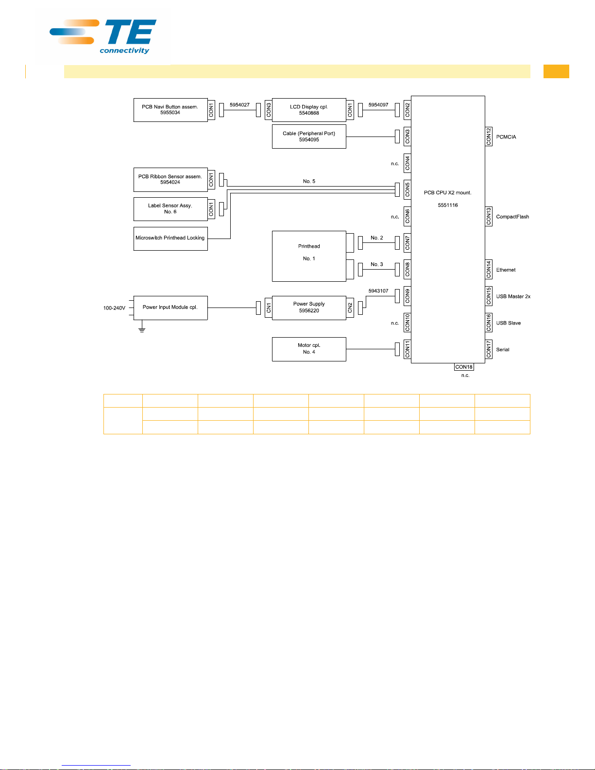
6 Block Diagram
Printer Type Nr. 1 Nr. 2 Nr. 3 Nr. 4 Nr. 5 Nr. 6
TE3112
TE3124
300dpi 5954072 5954067 5954066 5946208 5954099 5958670
600dpi 5954077 5954067 5954066 5946208 5954099 5958670
Fig. 23 Block diagram
Page 30
30 30
7 Layout Diagram PCB CPU
Fig. 24 Layout diagram PCB CPU - components side
Page 31
31
7 Layout Diagram PCB CPU
Fig. 25 Layout diagram PCB CPU - soldering side
Page 32

32 32
8 Index
A
Adjusting the belt tension .................25
Adjusting the head switch ................. 26
Adjusting the printhead position .......22
Adjusting the printhead pressure ...... 23
Adjusting the printing mechanism.....21
Adjusting the ribbon feed path .......... 24
B
Block diagram ................................... 29
C
Cleaning
by the operator .............................. 6
label sensor ..............................6, 7
E
Error Correction ........................... 27,28
F
Failure of device functions ................ 27
G
General safety instructions ................. 4
H
Handling electricity .............................5
Hardware faults ................................28
I
Internal rewinder
winding torque ............................19
L
Label sensor
cleaning ....................................6, 7
replacement ................................ 14
Layout diagram PCB CPU ................ 31
P
Printhead, replacing............................9
Procedure in case of accidents ..........5
Protective devices ..............................4
Pulling force ................................ 18, 19
R
Removing the plastic cover ................8
Replacing the label sensor ............... 14
Replacing the PCB CPU...................15
Replacing the power supply unit.......16
Replacing the printhead......................9
S
Slipping clutch
replacing ..................................... 11
winding torque ............................20
T
Tools ...................................................8
Torque.........................................18, 19
Transfer ribbon hubs
winding torque ............................20
Troubleshooting ................................28
V
Voltages, exposed ..............................5
W
Winding torque
adjusting .....................................20
internal rewinder .........................19
measuring ................................... 19
transfer ribbon hubs .................... 18
 Loading...