

Page 1

©2011 Tyco Electronics Japan G.K.,
a TE Connectivity Ltd. Company
All Rights Reserved
* Trademark
タイコエレクトロニクス ジャパン合同会社、TE Connectivity Ltd. グループ
1 of 31
TE logo is a trademark. Other products, logos, and company names might be trademarks of their respective owners. LOC B
409
-
7800
4
Customer Manual
取扱説明書
08 FEB
2012 Rev A
TE REC
TE RECTE REC
TE REC----Li25
Li25Li25
Li250000MMMM BATTERY OPERATED COMPRESSION TOOL
BATTERY OPERATED COMPRESSION TOOL BATTERY OPERATED COMPRESSION TOOL
BATTERY OPERATED COMPRESSION TOOL
TE REC
TE RECTE REC
TE REC----Li25
Li25Li25
Li250000MMMM バッテリー
バッテリーバッテリー
バッテリー油圧式工具
油圧式工具油圧式工具
油圧式工具
Part Number 2155363
Part Number 2155363Part Number 2155363
Part Number 2155363
部品番号
部品番号部品番号
部品番号 215536
215536 215536
2155363333
LANGUAGE 言語
ENGLISH FROM 2 of 31 to 14 of 31.
JAPANISE FROM 15 of 31 to 31 of 31.
英語
英語英語
英語 2 of 31 から 14 of 31.
日本語
日本語日本語
日本語 15 of 31 から 31 of 31.
この書類は当社により変更管理されており、必要に応じ変更されます。
最新の改訂に関しては当社本支店にお問い合わせ下さい。
This TE controlled document is subject to change. For latest revision call local TE representative.
Page 2

Customer Manual
取扱説明書 409-78004
Rev A 2 of 31
This Operator
This OperatorThis Operator
This Operator’’’’s Guide and S
s Guide and Ss Guide and S
s Guide and Service Manual contains details on using the equipment and important notes for its
ervice Manual contains details on using the equipment and important notes for its ervice Manual contains details on using the equipment and important notes for its
ervice Manual contains details on using the equipment and important notes for its
use
useuse
use
Please read and understand all of the instructions and safety information in this manual to operate the equipment
Please read and understand all of the instructions and safety information in this manual to operate the equipment Please read and understand all of the instructions and safety information in this manual to operate the equipment
Please read and understand all of the instructions and safety information in this manual to operate the equipment
safely.
safely.safely.
safely.
CONTENTS
CONTENTSCONTENTS
CONTENTS
Important Safety Precautions ……………………………………………………… 3 of 31
For Safe Operation …………………………………………………………………… 4 of 31
Precautions for the crimping tool …………………………………………………… 5 of 31
Precautions for the battery pack …………………………………………………… 5 of 31
Precautions for the battery charger ………………………………………………… 5 of 31
Parts and Standard Accessories …………………………………………………… 6 of 31
Options ………………………………………………………………………………… 7 of 31
Particular Use ………………………………………………………………………… 8 of 31
Specifications ………………………………………………………………………… 8 of 31
Guide to Compression Cycles for JIS(Japan Industrial Standard) Dies ………… 9 of 31
Combination table of dies and wire ………………………………………………… 9 of 31
Operating Instructions ……………………………………………………………… 10 of 31
Charging ……………………………………………………………………………… 10 of 31
Attaching and Detaching the Battery Pack …………………………………………11 of 31
Trigger and Release Button ………………………………………………………… 11 of 31
Crimping Operations ………………………………………………………………… 11 of 31
Install The Slide Pin …………………………………………………………………..13 of 31
Maintenance and Inspection …………………………………………………………14 of 31
Page 3

Customer Manual
取扱説明書 409-78004
Rev A 3 of 31
Important Safety Precautions
Important Safety PrecautionsImportant Safety Precautions
Important Safety Precautions
1. Use the battery and the charger designed for the tool
Use the battery designed for the tool
Do not charge the battery with the charger other than recommended in this instruction manual
Ensure that batteries are charged using the correct charger recommended in this instruction
manual. Incorrect use may result in a risk of electric shock, overheating or leakage of corrosive
liquid from the battery.
2. Charge the battery correctly
Use within the rated voltage for this unit
Use under AC power supply from a wall outlet. It can not be used with the portable generator or
DC power supply. Incorrect use may cause overheating of the battery or a fire.
Charge batteries at an ambient temperature of 10°C to 40°C.
Charge the battery in a well ventilated area.
Do not cover the charger or battery with a cloth on charge.
It may cause explosion of the battery or a fire.
Unplug the charger from the outlet to prevent a risk of electric shock or fire when not in use.
3. Do not short circuit the contacts of the battery
Attach a terminal cover if store a spare battery pack.
Short circuit in a flammable bag may cause explosion of the battery or a fire
4. Do not throw the battery pack in a fire
It may cause explosion of the battery or leakage of hazardous chemical substances.
5. In any of the following cases, retract the ram completely and remove the battery
Not in use or need repair
Changing dies or other attachments
A potentially hazardous condition
Activation of the tool may cause personal injury if the battery is attached.
6. Never operate the tool while the head is pointing in the direction of bystanders
The head may break and fly out
7. The use of any accessory or attachment is recommended
The use of any accessory or attachment, other than recommended in this instruction manual, may
present a risk of personal injury.
8. Warning for electric shock
Tools are NOT insulated for use on or near energized conductors. Use of these tools near
energized conductors may lead to electrical shock, causing severe injury or death. Do NOT use
these tools near energized conductors without adequately insulating operator and surroundings
Do not touch the AC plug or the battery pack with moistened hands. It may cause an electric
shock.
9. Prevent the risk of unintentional starting
Do not carry the tool with a finger on the trigger. Activation of the tool may cause personal injury.
10. Use safety glasses
Use safety glasses and if the operation is dusty, a face or dust mask
11. Work environment
Do not expose the tool to rain. Do not use the tool in damp or wet locatio
ns.
It may cause an electric shock or fumes from the tool.
Work in a well lighted area. Dark work environment may cause personal injury.
Do not use tools charge the battery in the presence of flammable liquids or gases.
It may cause explosion of the batter or a fire.
Page 4

Customer Manual
取扱説明書 409-78004
Rev A 4 of 31
For S
For SFor S
For Safe Operation
afe Operationafe Operation
afe Operation
1. Keep work area clean
Cluttered areas and benches injuries
2. Bystanders
Make sure all bystanders are clear of the work area when handling, starting and operating tool
3. Store batteries or idle tools
When not in use, tools and batteries should be stored separately in a dry environment and out of
reach of children or keep under lock and key.
Ensure that battery terminals must not be shorted by other metal parts such as screws, nails, etc.
Store or carry tools and batteries between –20℃ to 50℃.
4. Stay within the capacity of the tool
Do not exceed the capacity. And use the tool for manufacturer’s intended purpose only.
5. Use the right size tool
Do not use small tools or attachments to do heavier duty job. Do not use tool for purposes not
intended.
6. Dress properly
Do not wear loose clothing or jewelry, they can be caught in moving parts. Non-skid footwear and
rubber gloves are recommended when working outdoors. Wear safety cap to protect the head.
7. . Do not over-reach
Keep proper footing and balance at all times.
8. Stay alert
Stay alert with the work. Use common sense. Do not operate the tool when you are tired
9. Do not abuse the cord of the charger
Do not carry the charger by the cord. Do not yank the cord to disconnect from the outlet.
Keep the cord clear of heat, oil, and an accessible sharp point
10. Use the extension cord for outdoor use
Use cabtire type extension cord when charging outdoor
11. Maintain tools with care
Keep the tool clean for better and safer performance. Follow instructions for lubrication.
Inspect the charger cord periodically and if damaged have repaired by an authorized service
facility
Inspect the extension cord periodically and if damaged , replace with new one.
Always keep the grip of the tool clean and dry and free of oil and grease.
12. Check damaged parts
Do not operate the tool if it is damaged, improperly adjusted or not completely and correctly
assembled.
Check for alignment of moving parts, smooth running of moving parts, breakage of parts,
mounting and any other condition that may affect its operation. If damaged, it should be properly
repaired or replaced by an authorized service facility.
Have defective switches replaced by an authorized service facility. Do not use the tool if the
switch does turn it on and off.
13. Have your tool repaired by an authorized service center
This tool is constructed in accordance with the relevant safety requirements. Repairs should
only be carried out by a qualified person using original spare parts, otherwise this may result in
considerable danger to the user.
Page 5

Customer Manual
取扱説明書 409-78004
Rev A 5 of 31
Precautions for the c
Precautions for the cPrecautions for the c
Precautions for the crimping tool
rimping toolrimping tool
rimping tool
This tool is designed to an average operating life of 11.000 times of crimping. Do not use the
tool after this operating life is over.
Select the appropriate male and female indent dies combination for the connector to be crimped
Incorrect combinations will result in inferior connection of the conductors.
Do not operate the tool without dies and a connector in place.
If operating this tool at a temperature of less than -5°C, allow the tool to stand at a room
temperature of between 10°-25°C for 1 hour before using the tool. This is to ensure the smooth
flow of the hydraulic oil and correct operation of the tool.
The valve cartridge is activated and a click is heard when crimping is completed.
The yellow band around the ram becomes visible when the ram is fully extended.
If the yellow band does not became visible, stop the operation and check the condition of the
tool.
Turn the Slide pin counterclockwise to release the lock when pulling it out.
Do not tap the Slide pin with a hammer when it is locked. It may break the Slide pin.
Precautions for the battery pa
Precautions for the battery paPrecautions for the battery pa
Precautions for the battery pack
ckck
ck
Do not short circuit the contacts
Do not expose the pack to water, oil or solvents.
Do not disassemble, modify or attempt to repair the battery pack
Do not dispose of the battery pack in a fire or as domestic garbage
Do not drop or otherwise abuse the battery pack.
Do not leave the battery pack in locations where it is exposed to a temperature greater than
40 for an extended period.
℃
Do not short circuit the battery by attaching foreign materials to the contacts.
Stop using the battery pack if rusting on the contacts appear.
To maintain long life of the Li-Ion battery, the protection feature to stop the output is installed.
When the trigger is pressed with low battery capacity, the motor stops. It is the function of the
protection feature and not an electrical breakdown. Charge the battery if it happens.
Precautions for the
Precautions for the Precautions for the
Precautions for the battery
battery battery
battery charger
chargercharger
charger
The LED indicator lights in green and remains lit when the unit starts charging a battery pack. The
indicator changes to orange when charging is completed.
This unit is for charging battery packs BP-14LN only. Do not use the charger for any other devices.
Allow battery packs to cool down before charging. Allow at least 15 minutes between charges
when charging several packs in succession.
The charging time is approximately 25 minutes (80% capacity) and 45 minutes(100% capacity).
Never short circuit the output terminals.
Do not expose the charger to water, oil or solvents.
Do not disassemble or attempt to modify the charger.
Do not drop or otherwise abuse the charger.
Page 6

Customer Manual
取扱説明書 409-78004
Rev A 6 of 31
PPPParts and S
arts and Sarts and S
arts and Standard Accessories
tandard Accessoriestandard Accessories
tandard Accessories
●●●●Battery Operated Crimping Tool
Battery Operated Crimping ToolBattery Operated Crimping Tool
Battery Operated Crimping Tool
【【【【REC‐Li
REC‐LiREC‐Li
REC‐Li250M
250M250M
250M】】】】
●Battery pack
●Battery pack ●Battery pack
●Battery pack 【【【【BP
BPBP
BP----14LN
14LN14LN
14LN】】】】
●●●●JIS
JISJIS
JIS (Japan Industrial Standard)
(Japan Industrial Standard) (Japan Industrial Standard)
(Japan Industrial Standard)
Indent die
Indent die Indent die
Indent die ((((6
6 6
6 pieces)
pieces)pieces)
pieces) //// Nest die
Nest die Nest die
Nest die ((((4444 piec
piecpiec
pieces
eses
es))))
●Charger
●Charger ●Charger
●Charger 【【【【CH
CHCH
CH----25LNW
25LNW25LNW
25LNW】】】】
●Carrying case
●Carrying case●Carrying case
●Carrying case
●Terminal
●Terminal●Terminal
●Terminal cover
covercover
cover
Attach a terminal cover when not
in use for short circuit protection.
Page 7

Customer Manual
取扱説明書 409-78004
Rev A 7 of 31
Options
OptionsOptions
Options
●●●●Shou
ShouShou
Shoulder
lderlder
lder strap
strapstrap
strap
●●●●Attachments
AttachmentsAttachments
Attachments
The tool can be used for other purposes by changing attachments.
The tool can be used for other purposes by changing attachments. The tool can be used for other purposes by changing attachments.
The tool can be used for other purposes by changing attachments.
Description Model No, Capacity and Remarks
Cable Cutter 200AT-50YC Cu 3×150mm2(46mmOD)
Cu 500mm2(45mmOD)
Threaded bar Cutter 200AT-13WT W3/8” Soft steel(ss),Stainless
W1/2” Soft steel(ss),Stainless
Re-bar Cutter 200AT-S16 16mm rebar, soft steel bar
SS41, MAX SD35
Angle Steel Puncher 200AT-AP18 Punching capacity:φ10.5mm, φ13.5mm, φ17.5mm holes on
6mm thickness steel
Knock out Puncher 200AT-9PD Punching capacity: up to B104(115.5mm) diameter hole on
3.2mm thickness mild steel
Raceway Cutter
Raceway cutter 150AT-DCM
Cutter cassette D1
Cutter cassette S-D1
Cutter cassette D2
Cutter cassette D15
Cutter cassette P-1
Cutter cassette P-2
Raceway attachment 200AD-DCM
200AD-DCM is required when attaching a 150AT-DCM to
TE REC-Li250M.
Applicable raceway: D1, DP1
Applicable raceway: S-D1
Applicable raceway: D2, DP2
Applicable raceway: D15
Applicable raceway: P-1
Applicable raceway: P-2
It is required when attaching a 150AT-DCM to TE REC-Li250M.
Page 8

Customer Manual
取扱説明書 409-78004
Rev A 8 of 31
Particular Use
Particular UseParticular Use
Particular Use
REC
RECREC
REC----Li250M
Li250MLi250M
Li250M::::To indent crimp
To indent crimp To indent crimp
To indent crimp ffff
or non insulated terminals and sleeves
or non insulated terminals and sleevesor non insulated terminals and sleeves
or non insulated terminals and sleeves
14
14 14
14----250mm2
250mm2250mm2
250mm2
Specifications
SpecificationsSpecifications
Specifications
Tool
ToolTool
Tool: REC
: REC: REC
: REC----Li250M
Li250MLi250M
Li250M
Output force:
Output force: Output force:
Output force: 127
127127
127KN
KNKN
KN
Applicable range: 14
Applicable range: 14Applicable range: 14
Applicable range: 14----250mm2( For Non insulated terminals and sleeves)
250mm2( For Non insulated terminals and sleeves)250mm2( For Non insulated terminals and sleeves)
250mm2( For Non insulated terminals and sleeves)
Motor:
Motor: Motor:
Motor: 14.4 V DC Motor
14.4 V DC Motor14.4 V DC Motor
14.4 V DC Motor
Dimensions (L x H x W):
Dimensions (L x H x W): Dimensions (L x H x W):
Dimensions (L x H x W): 34
3434
345
5 5
5 xxxx300
300300
300 x
x x
x 75
75 75
75 mm
mm mm
mm
Weight:
Weight: Weight:
Weight: 4.3
4.3 4.3
4.3 kg (
kg ( kg (
kg (with
withwith
with battery
battery battery
battery and dies for 200mm2
and dies for 200mm2 and dies for 200mm2
and dies for 200mm2))))
Battery Pack (BP
Battery Pack (BPBattery Pack (BP
Battery Pack (BP----14LN
14LN 14LN
14LN ))))
Battery Type
Battery Type Battery Type
Battery Type Lithium
LithiumLithium
Lithium----Ion
IonIon
Ion Battery
Battery Battery
Battery
Output
Output Output
Output 14.4 V DC
14.4 V DC14.4 V DC
14.4 V DC
Capacity
Capacity Capacity
Capacity 3.0 A
3.0 A3.0 A
3.0 Ahhhh
Charging Time
Charging Time Charging Time
Charging Time Approx 25
Approx 25 Approx 25
Approx 25 min
min min
min (80
(80 (80
(80%%%% capacity)
capacity)capacity)
capacity)
Approx 45 min (100
Approx 45 min (100 Approx 45 min (100
Approx 45 min (100%%%% capacity
capacity capacity
capacity))))
Dimensions(L x H x W)
Dimensions(L x H x W) Dimensions(L x H x W)
Dimensions(L x H x W) 107
107107
107 x
x x
x 65
6565
65 x
x x
x 84
8484
84 mm
mm mm
mm
Weight
Weight Weight
Weight 0.
0.0.
0.57
57 57
57 kg
kgkg
kg
Battery
Battery Battery
Battery Charger
Charger Charger
Charger CH
CHCH
CH----25LNW
25LNW25LNW
25LNW
Input Voltage
Input Voltage Input Voltage
Input Voltage 100
100100
100----240
240240
240 V Single Phase
V Single Phase V Single Phase
V Single Phase
Input Frequency
Input Frequency Input Frequency
Input Frequency 50/
50/50/
50/60 Hz
60 Hz 60 Hz
60 Hz
Input C
Input CInput C
Input Capacity
apacity apacity
apacity 145VA(100V)
145VA(100V)145VA(100V)
145VA(100V)----148VA(
148VA(148VA(
148VA(222244440V
0V0V
0V))))
Dimensions
Dimensions Dimensions
Dimensions 230
230230
230 x
x x
x 80
8080
80 x
x x
x 145
145145
145 mm
mm mm
mm
Weight
Weight Weight
Weight 1.6
1.61.6
1.6 kg
kg kg
kg
Page 9

Customer Manual
取扱説明書 409-78004
Rev A 9 of 31
Guide to Compression Cycles
Guide to Compression CyclesGuide to Compression Cycles
Guide to Compression Cycles
FFFFor JIS(Japan Industrial Standard) DIES
or JIS(Japan Industrial Standard) DIES or JIS(Japan Industrial Standard) DIES
or JIS(Japan Industrial Standard) DIES
This guide indicates the number of
This guide indicates the number of This guide indicates the number of
This guide indicates the number of crimpi
crimpicrimpi
crimping cycles that the tools can be exp
ng cycles that the tools can be expng cycles that the tools can be exp
ng cycles that the tools can be expected to perform when the battery is
ected to perform when the battery is ected to perform when the battery is
ected to perform when the battery is
fully
fullyfully
fully charged. These figures are approximate and may vary according to the charging conditions.
charged. These figures are approximate and may vary according to the charging conditions.charged. These figures are approximate and may vary according to the charging conditions.
charged. These figures are approximate and may vary according to the charging conditions.
When the compression capacity is reduced to about 1/2 of a normal cycle, this indicates that the battery life is
When the compression capacity is reduced to about 1/2 of a normal cycle, this indicates that the battery life is When the compression capacity is reduced to about 1/2 of a normal cycle, this indicates that the battery life is
When the compression capacity is reduced to about 1/2 of a normal cycle, this indicates that the battery life is
exhausted
exhausted exhausted
exhausted and
andand
and the battery pack should be replaced with a new one. .
the battery pack should be replaced with a new one. .the battery pack should be replaced with a new one. .
the battery pack should be replaced with a new one. .
Conductor size The number of crimps per charge
14mm2 230 times
22 mm2 205 times
38mm2 180 times
60mm2 175 times
70mm2 130 times
80mm2 145 times
100 mm2 95 times
150 mm2 85 times
200 mm2 55 times
250 mm2 50 times
Page 10

Customer Manual
取扱説明書 409-78004
Rev A 10 of 31
OOOOPERATING INSTRUCTIONS
PERATING INSTRUCTIONSPERATING INSTRUCTIONS
PERATING INSTRUCTIONS
Charging
ChargingCharging
Charging
1111....Connect the AC Plug of the Charger CH
Connect the AC Plug of the Charger CHConnect the AC Plug of the Charger CH
Connect the AC Plug of the Charger CH----25LNW
25LNW 25LNW
25LNW
to an AC outlet.
to an AC outlet. to an AC outlet.
to an AC outlet.
The Indicator
The IndicatorThe Indicator
The Indicator Lamp blinks [STAND BY] in red
Lamp blinks [STAND BY] in redLamp blinks [STAND BY] in red
Lamp blinks [STAND BY] in red
Note:
The rated voltage for this unit is 100V-240V.
Use of voltages over 260V will result in
damage to the charger.
2222....Insert the Battery firmly to the
Insert the Battery firmly to the Insert the Battery firmly to the
Insert the Battery firmly to the charger
chargercharger
charger....
The Indicator Lamp lights [UNDER
The Indicator Lamp lights [UNDERThe Indicator Lamp lights [UNDER
The Indicator Lamp lights [UNDER
CHARGING] in green.
CHARGING] in green.CHARGING] in green.
CHARGING] in green.
Note:
Do not short-circuit the Charger by placing
foreign materials in the terminals on charger, as this
will damage the Charger.
3333....Charging takes approximately
Charging takes approximately Charging takes approximately
Charging takes approximately 25
2525
25 minutes
minutes minutes
minutes(80% capacity) and 45
(80% capacity) and 45(80% capacity) and 45
(80% capacity) and 45minutes
minutesminutes
minutes(100% capacity).
(100% capacity). (100% capacity).
(100% capacity).
When charging is finished, the Indicator
When charging is finished, the IndicatorWhen charging is finished, the Indicator
When charging is finished, the Indicator Lamp lights [COMPLETION] in orange.
Lamp lights [COMPLETION] in orange.Lamp lights [COMPLETION] in orange.
Lamp lights [COMPLETION] in orange.
Note:
If the Indicator Lamp displays [HIGH TEMPERATURE] , remove the Battery from the Charger and allow it to cool
down before trying to charge it again.
4444.
..
.
When the battery becomes dead and no longer can be used, the indicator flashes in red quickly
When the battery becomes dead and no longer can be used, the indicator flashes in red quicklyWhen the battery becomes dead and no longer can be used, the indicator flashes in red quickly
When the battery becomes dead and no longer can be used, the indicator flashes in red quickly
[DEAD BATTERY].
[DEAD BATTERY].[DEAD BATTERY].
[DEAD BATTERY].
5555....When the charger is out of order
When the charger is out of orderWhen the charger is out of order
When the charger is out of order, the indicator does not light up even if AC power is supplied.
, the indicator does not light up even if AC power is supplied., the indicator does not light up even if AC power is supplied.
, the indicator does not light up even if AC power is supplied.
Note:
AC power supply must be a wall outlet. It can not be used with the portable generator.
LED lamp
Status
Red lamp blinks
(every second)
Stand by
The charger is powered.
Green lamp lights Under charging
Green lamp blinks
(0.3sec-on / 0.3sec-off)
80% completion
The battery has been charged
approx 80% of its capacity.
Orange lamp lights
Completion
The battery has been fully
charged.
Green lamp blinks
(every second)
Auxiliary charging
The battery is charged with a
low current.
Red lamp lights
High or low temperature
Waiting for becoming proper
to charge temperature of
battery pack.
Red lamp blinks
(0.3sec-on / 0.3sec-off)
Impossible to charge
Page 11
Customer Manual
取扱説明書 409-78004
Rev A 11 of 31
Attaching
Attaching Attaching
Attaching and Detaching
and Detaching and Detaching
and Detaching the Battery Pac
the Battery Pacthe Battery Pac
the Battery Packkkk
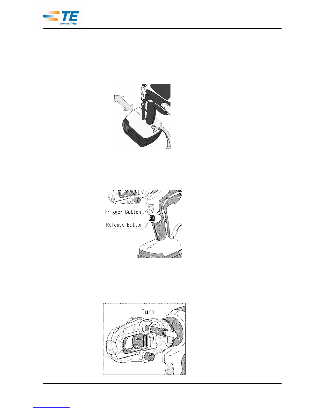
1.
1.1.
1. To attach the battery pack, slide
To attach the battery pack, slideTo attach the battery pack, slide
To attach the battery pack, slide it into the tool until it stops
it into the tool until it stopsit into the tool until it stops
it into the tool until it stops.
. .
.
2.
2.2.
2. To detach the Battery Pack,
To detach the Battery Pack, To detach the Battery Pack,
To detach the Battery Pack, pulling out t
pulling out tpulling out t
pulling out the
he he
he battery
batterybattery
battery pack
pack pack
pack while pressing the latches
while pressing the latcheswhile pressing the latches
while pressing the latches....
3.
3.3.
3. After inserting
After inserting After inserting
After inserting the
thethe
the bbbbattery Pack, check it is securely in
attery Pack, check it is securely inattery Pack, check it is securely in
attery Pack, check it is securely in place by pulling it gently.
place by pulling it gently.place by pulling it gently.
place by pulling it gently.
Do not press t
Do not press tDo not press t
Do not press the Latch
he Latchhe Latch
he Latches
eses
es when pulling the battery
when pulling the batterywhen pulling the battery
when pulling the battery....
Trigger & Release Button
Trigger & Release ButtonTrigger & Release Button
Trigger & Release Button
The Ram advances when the
The Ram advances when the The Ram advances when the
The Ram advances when the Switch Knob
Switch KnobSwitch Knob
Switch Knob is pressed and stops
is pressed and stops is pressed and stops
is pressed and stops when the Switch Knob is released.
when the Switch Knob is released.when the Switch Knob is released.
when the Switch Knob is released.
To retract the Ram, press the Release
To retract the Ram, press the Release To retract the Ram, press the Release
To retract the Ram, press the Release lever
leverlever
lever. The Ram co
. The Ram co. The Ram co
. The Ram continues to
ntinues tontinues to
ntinues to retract while the Release
retract while the Release retract while the Release
retract while the Release lever
leverlever
lever is pressed.
is pressed. is pressed.
is pressed.
CRIMPING OPERATIONS
CRIMPING OPERATIONSCRIMPING OPERATIONS
CRIMPING OPERATIONS
1.
1.1.
1. Select an appropriate size of die for the connector
Select an appropriate size of die for the connector Select an appropriate size of die for the connector
Select an appropriate size of die for the connector
2.
2.2.
2. Turn the Slide pin counterclockwise to release the lock and pull it out
Turn the Slide pin counterclockwise to release the lock and pull it outTurn the Slide pin counterclockwise to release the lock and pull it out
Turn the Slide pin counterclockwise to release the lock and pull it out....
Page 12

Customer Manual
取扱説明書 409-78004
Rev A 12 of 31
3.
3.3.
3. Insert
Insert Insert
Insert Nest
NestNest
Nest die into the Yoke
die into the Yoke die into the Yoke
die into the Yoke and the Indent
and the Indent and the Indent
and the Indent die
die die
die adapter and the Indent die
adapter and the Indent die adapter and the Indent die
adapter and the Indent die to the
to the to the
to the Ram securely
Ram securelyRam securely
Ram securely....
4.
4.4.
4. Close the Yoke and push the Slide pin in securely.
Close the Yoke and push the Slide pin in securely.Close the Yoke and push the Slide pin in securely.
Close the Yoke and push the Slide pin in securely.
5.
5.5.
5. Turn the Slide pin clockwise to lock. If the Slide pin is not locked securely, it
Turn the Slide pin clockwise to lock. If the Slide pin is not locked securely, it Turn the Slide pin clockwise to lock. If the Slide pin is not locked securely, it
Turn the Slide pin clockwise to lock. If the Slide pin is not locked securely, it may break during the
may break during the may break during the
may break during the
operation.
operation.operation.
operation.
6.
6.6.
6. The head is 180
The head is 180The head is 180
The head is 180°°°°rotatable. Rotate the head to the desired position for the job.
rotatable. Rotate the head to the desired position for the job.rotatable. Rotate the head to the desired position for the job.
rotatable. Rotate the head to the desired position for the job.
7.
7.7.
7. Place the connector and p
Place the connector and pPlace the connector and p
Place the connector and press the Trigger and advance the ram so that
ress the Trigger and advance the ram so thatress the Trigger and advance the ram so that
ress the Trigger and advance the ram so that the connector is held between
the connector is held between the connector is held between
the connector is held between
the die
the diethe die
the dies.
s.s.
s.
8.
8.8.
8. When crimping terminal or sleeve(P), i
When crimping terminal or sleeve(P), iWhen crimping terminal or sleeve(P), i
When crimping terminal or sleeve(P), insert the conductor
nsert the conductor nsert the conductor
nsert the conductor until it sticks out 1mm from its barrel edge
until it sticks out 1mm from its barrel edgeuntil it sticks out 1mm from its barrel edge
until it sticks out 1mm from its barrel edge....
When crimping sleeve(B), insert the conductor as far as it goes.
When crimping sleeve(B), insert the conductor as far as it goes. When crimping sleeve(B), insert the conductor as far as it goes.
When crimping sleeve(B), insert the conductor as far as it goes.
9.
9. 9.
9. Press the Trigger until the compression is
Press the Trigger until the compression isPress the Trigger until the compression is
Press the Trigger until the compression is completed.
completed. completed.
completed.
A click will be heard w
A click will be heard wA click will be heard w
A click will be heard when completed.
hen completed.hen completed.
hen completed. The black band around the
The black band around the The black band around the
The black band around the
Ram becomes visible when the Ram is fully extended.
Ram becomes visible when the Ram is fully extended. Ram becomes visible when the Ram is fully extended.
Ram becomes visible when the Ram is fully extended.
10.
10. 10.
10. Press the Release
Press the Release Press the Release
Press the Release lever
leverlever
lever to retract the Ram. The Ram
to retract the Ram. The Ram to retract the Ram. The Ram
to retract the Ram. The Ram continues to retract while the Release
continues to retract while the Releasecontinues to retract while the Release
continues to retract while the Release lever
lever lever
lever is
is is
is
pressed. The
pressed. Thepressed. The
pressed. The Ram stops when it reaches the low
Ram stops when it reaches the lowRam stops when it reaches the low
Ram stops when it reaches the lower end.
er end.er end.
er end.
11.
11.11.
11. To release and pull out the Slide pin, follow the procedure as described in step 2.
To release and pull out the Slide pin, follow the procedure as described in step 2. To release and pull out the Slide pin, follow the procedure as described in step 2.
To release and pull out the Slide pin, follow the procedure as described in step 2.
12.
12.12.
12. Open the Yoke and remove the crimped conductor.
Open the Yoke and remove the crimped conductor.Open the Yoke and remove the crimped conductor.
Open the Yoke and remove the crimped conductor.
13.
13.13.
13. If crimping 200mm2 or 250mm2, change the Yoke and follow the steps from step 2.
If crimping 200mm2 or 250mm2, change the Yoke and follow the steps from step 2.If crimping 200mm2 or 250mm2, change the Yoke and follow the steps from step 2.
If crimping 200mm2 or 250mm2, change the Yoke and follow the steps from step 2.
Note: To maintain long life of the Li-Ion battery, the protection feature to stop the output is installed. When
the trigger is pressed with low battery capacity, the motor stops. It is the function of the protection
feature and not an electrical breakdown. Charge the battery if it happens.
Page 13

Customer Manual
取扱説明書 409-78004
Rev A 13 of 31
Install The Slide Pin
Caution
Use the Slide pin, the stopper pin, and the spring compatible with the tool. The tool may damage if
Use the Slide pin, the stopper pin, and the spring compatible with the tool. The tool may damage if Use the Slide pin, the stopper pin, and the spring compatible with the tool. The tool may damage if
Use the Slide pin, the stopper pin, and the spring compatible with the tool. The tool may damage if
incompatible parts are applied.
incompatible parts are applied.incompatible parts are applied.
incompatible parts are applied.
Ensure that the hole of the slide pin is not deformed or cracked. If such deformations o
Ensure that the hole of the slide pin is not deformed or cracked. If such deformations oEnsure that the hole of the slide pin is not deformed or cracked. If such deformations o
Ensure that the hole of the slide pin is not deformed or cracked. If such deformations or cracks appear,
r cracks appear, r cracks appear,
r cracks appear,
contact an
contact an contact an
contact an authorized
authorizedauthorized
authorized service facility.
service facility. service facility.
service facility.
When replacing the Slide pin, remove the battery from the tool to prevent unintentional starting
When replacing the Slide pin, remove the battery from the tool to prevent unintentional startingWhen replacing the Slide pin, remove the battery from the tool to prevent unintentional starting
When replacing the Slide pin, remove the battery from the tool to prevent unintentional starting
Repair parts and tool
Repair parts and toolRepair parts and tool
Repair parts and tool
Necessary parts
Necessary parts Necessary parts
Necessary parts and tool to replace the slide pin are as follows
and tool to replace the slide pin are as followsand tool to replace the slide pin are as follows
and tool to replace the slide pin are as follows
Installation procedure
Installation procedureInstallation procedure
Installation procedure
1.
1.1.
1. Insert the Spring and the Stopper pin coated with grease into the hole of the Cylinder head in order.
Insert the Spring and the Stopper pin coated with grease into the hole of the Cylinder head in order.Insert the Spring and the Stopper pin coated with grease into the hole of the Cylinder head in order.
Insert the Spring and the Stopper pin coated with grease into the hole of the Cylinder head in order.
2.
2.2.
2. Insert the piano
Insert the piano Insert the piano
Insert the piano wire from the hole of the Cylinder head. While pushing the Stopper pin with the Piano wire,
wire from the hole of the Cylinder head. While pushing the Stopper pin with the Piano wire, wire from the hole of the Cylinder head. While pushing the Stopper pin with the Piano wire,
wire from the hole of the Cylinder head. While pushing the Stopper pin with the Piano wire,
insert the Slide pin coated with grease.
insert the Slide pin coated with grease.insert the Slide pin coated with grease.
insert the Slide pin coated with grease.
3.
3.3.
3. Under the condition of Step 2, push the Slide pin in while pulling out the Piano wire.
Under the condition of Step 2, push the Slide pin in while pulling out the Piano wire.Under the condition of Step 2, push the Slide pin in while pulling out the Piano wire.
Under the condition of Step 2, push the Slide pin in while pulling out the Piano wire.
4.
4.4.
4. Under the condition of Step 3, turn the Slide pin and place the Stopper pin into the groove
Under the condition of Step 3, turn the Slide pin and place the Stopper pin into the groove Under the condition of Step 3, turn the Slide pin and place the Stopper pin into the groove
Under the condition of Step 3, turn the Slide pin and place the Stopper pin into the groove
5.
5.5.
5. Push in the Slide pin completely. Turn the Slide pin clockwise approximately 40
Push in the Slide pin completely. Turn the Slide pin clockwise approximately 40Push in the Slide pin completely. Turn the Slide pin clockwise approximately 40
Push in the Slide pin completely. Turn the Slide pin clockwise approximately 40°°°°and confirm the Slide pin is
and confirm the Slide pin is and confirm the Slide pin is
and confirm the Slide pin is
securely locked and
securely locked and securely locked and
securely locked and not pulling out.
not pulling out.not pulling out.
not pulling out.
6.
6.6.
6. Release the lock and check insertion and extraction of the Slide pin is smooth without wobbling or pulling out
Release the lock and check insertion and extraction of the Slide pin is smooth without wobbling or pulling outRelease the lock and check insertion and extraction of the Slide pin is smooth without wobbling or pulling out
Release the lock and check insertion and extraction of the Slide pin is smooth without wobbling or pulling out
* Due to improvements to conventional parts, the external design of the Slide pin may change.
* Due to improvements to conventional parts, the external design of the Slide pin may change.* Due to improvements to conventional parts, the external design of the Slide pin may change.
* Due to improvements to conventional parts, the external design of the Slide pin may change.
Page 14

Customer Manual
取扱説明書 409-78004
Rev A 14 of 31
MAINTENANCE AND INSPECTION
MAINTENANCE AND INSPECTIONMAINTENANCE AND INSPECTION
MAINTENANCE AND INSPECTION
1.
1.1.
1. Daily
DailyDaily
Daily maintenance is required to ensure that the tool
maintenance is required to ensure that the tool maintenance is required to ensure that the tool
maintenance is required to ensure that the tool is kept in good working condition.
is kept in good working condition. is kept in good working condition.
is kept in good working condition.
2.
2.2.
2. Do not store the tool in a humid environment.
Do not store the tool in a humid environment.Do not store the tool in a humid environment.
Do not store the tool in a humid environment.
3.
3.3.
3. If tool is broken at more than 11,000 times normal operation, do not replace the broken parts and use the
If tool is broken at more than 11,000 times normal operation, do not replace the broken parts and use the If tool is broken at more than 11,000 times normal operation, do not replace the broken parts and use the
If tool is broken at more than 11,000 times normal operation, do not replace the broken parts and use the
tool again. This is
tool again. This istool again. This is
tool again. This is the end of the tool life.
the end of the tool life. the end of the tool life.
the end of the tool life.
4.
4.4.
4. Clean the plastic parts with soapy cloth if they get dirty or dusty.
Clean the plastic parts with soapy cloth if they get dirty or dusty.Clean the plastic parts with soapy cloth if they get dirty or dusty.
Clean the plastic parts with soapy cloth if they get dirty or dusty.
5.
5.5.
5. Attach a terminal cover if store a spare battery pack to prevent short circuit.
Attach a terminal cover if store a spare battery pack to prevent short circuit.Attach a terminal cover if store a spare battery pack to prevent short circuit.
Attach a terminal cover if store a spare battery pack to prevent short circuit.
6.
6.6.
6. Change the hydraulic oil every 24 months.
Change the hydraulic oil every 24 months.Change the hydraulic oil every 24 months.
Change the hydraulic oil every 24 months. Regular
Regular Regular
Regular maintenance
maintenance maintenance
maintenance by an authorized
by an authorized by an authorized
by an authorized service facility
service facility service facility
service facility is
is is
is
rrrrecommended
ecommendedecommended
ecommended....
Page 15

Customer Manual
取扱説明書 409-78004
Rev A 15 of 31
この
このこの
この取扱説明書
取扱説明書取扱説明書
取扱説明書はははは本機
本機本機
本機のののの取取取取りりりり扱扱扱扱いいいい、、、、注意事項
注意事項注意事項
注意事項などについて
などについてなどについて
などについて
説明
説明説明
説明してありますのでご
してありますのでごしてありますのでご
してありますのでご使用前
使用前使用前
使用前によくお
によくおによくお
によくお読読読読みのうえ
みのうえみのうえ
みのうえ、、、、
正正正正しく
しくしく
しく安全
安全安全
安全にご
にごにご
にご使用
使用使用
使用ください
くださいください
ください。。。。
目次
安全上のご注意 ・・・・・・・・・・・・・・・・・・・・・・・・・ 16 of 31
バッテリー油圧式工具使用上の注意 ・・・・・・・・ 20 of 31
各部の名称および標準付属品 ・・・・・・・・・・・・・ 21 of 31
オプション(別売品)のご案内 ・・・・・・・・・・・・・・ 22 of 31
用途 ・・・・・・・・・・・・・・・・・・・・・・・・・・・・・・・・・・ 23 of 31
仕様 ・・・・・・・・・・・・・・・・・・・・・・・・・・・・・・・・・・ 23 of 31
標準圧着可能回数 ・・・・・・・・・・・・・・・・・・・・・・ 24 of 31
ダイスと電線の組合せ表 ・・・・・・・・・・・・・・・・・ 24 of 31
使用方法 ・・・・・・・・・・・・・・・・・・・・・・・・・・・・・・ 25 of 31
スライドピンの取付け手順 ・・・・・・・・・・・・・・・・ 29 of 31
保守・点検 ・・・・・・・・・・・・・・・・・・・・・・・・・・・・・ 31 of 31
修理のときは ・・・・・・・・・・・・・・・・・・・・・・・・・・・ 31 of 31
Page 16

Customer Manual
取扱説明書 409-78004
Rev A 16 of 31
・・・・安全上
安全上安全上
安全上のご
のごのご
のご注意
注意注意
注意
Page 17
Customer Manual
取扱説明書 409-78004
Rev A 17 of 31
Page 18

Customer Manual
取扱説明書 409-78004
Rev A 18 of 31
Page 19

Customer Manual
取扱説明書 409-78004
Rev A 19 of 31
Page 20

Customer Manual
取扱説明書 409-78004
Rev A 20 of 31
・・・・バッテリー
バッテリーバッテリー
バッテリー油圧式工具使用上
油圧式工具使用上油圧式工具使用上
油圧式工具使用上のご
のごのご
のご注意
注意注意
注意
Page 21

Customer Manual
取扱説明書 409-78004
Rev A 21 of 31
・・・・各部
各部各部
各部のののの名称
名称名称
名称および
およびおよび
および標準付属品
標準付属品標準付属品
標準付属品
バッテリー式油圧工具 TE REC-Li250M
Page 22

Customer Manual
取扱説明書 409-78004
Rev A 22 of 31
・・・・オプション
オプションオプション
オプション((((別売品
別売品別売品
別売品))))のご
のごのご
のご案内
案内案内
案内
・肩かけベルト
・アタッチメント
本工具は下記のアタッチメントを使用することにより各作業が行えます。
種 類 型 式 仕様 ・ 備考
ケーブルカッタ 200AT-50YC 600V-CV: 150㎟ 3芯(φ46)
600V-CV: 500㎟ 単芯(φ38)
全ネジカッタ 200AT-13WT 軟鋼全ネジボルト W3/8, W1/2
ステンレス全ネジボルト W3/8, W1/2
鉄筋カッタ 200AT-S16 鉄筋コンクリート用棒鋼、軟鋼材: SS41, SD35以下、
D16 (φ15.8) 以下
アングルパンチャ 200AT-AP18 穴径:φ10.5, φ13.5 φ17.5
等辺山形鋼: 50x50xt6mm、 平鋼: 50xt6mm
ダクター: D1, D2, D15 チャンネル: S-D1, S-D2
パンチャ 200AT-9PD 軟鋼板: SPCC T3.2mm
レースウェイカッタ
レースウェイカッタ 150AT-DCM
カッタカセット D1
カッタカセット S-D1
カッタカセット D2
カッタカセット D15
カッタカセット P-1
カッタカセット P-2
レースウェイ 200AD-DCM
アタッチメント
レースウェイカッタ150AT-DCMをTE REC-Li250Mに取り付ける
には、レースウェイアタッチメント200AD-DCMが必要です。
適用切断物: D1, DP1
適用切断物: S-D1
適用切断物: D2, DP2
適用切断物: D15
適用切断物: P-1
適用切断物: P-2
レースウェイカッタ150AT-DCMをTE REC-Li250Mに取り付ける
際に使用します。
Page 23

Customer Manual
取扱説明書 409-78004
Rev A 23 of 31
・・・・用途
用途用途
用途
・・・・仕様
仕様仕様
仕様
・バッテリー油圧式工具 TE REC-Li250M
・バッテリーパック BP-14LN
・充電器 CH-25LNW
注意
注意注意
注意::::バッテリーパック
バッテリーパックバッテリーパック
バッテリーパック BP
BPBP
BP----14LN
14LN14LN
14LN はははは、、、、充電器
充電器充電器
充電器 CH
CHCH
CH----25LNW
25LNW25LNW
25LNW 以外
以外以外
以外のののの充電器
充電器充電器
充電器でででで充電
充電充電
充電することはできません
することはできませんすることはできません
することはできません。。。。
Page 24

Customer Manual
取扱説明書 409-78004
Rev A 24 of 31
・・・・標準圧着可能回数
標準圧着可能回数標準圧着可能回数
標準圧着可能回数 ((((1111 回回回回のののの満充電
満充電満充電
満充電でででで可能
可能可能
可能なななな圧着回数
圧着回数圧着回数
圧着回数のののの目安
目安目安
目安))))
・・・・ダイス
ダイスダイス
ダイスとととと電線
電線電線
電線のののの組合
組合組合
組合せせせせ表表表表
Page 25

Customer Manual
取扱説明書 409-78004
Rev A 25 of 31
・・・・使用方法
使用方法使用方法
使用方法
注意
注意注意
注意::::正正正正しい
しいしい
しい充電
充電充電
充電をしても
をしてもをしても
をしても、、、、バッテリーパック
バッテリーパックバッテリーパック
バッテリーパックのののの使用時間
使用時間使用時間
使用時間がががが著著著著しく
しくしく
しく低下
低下低下
低下してきたときは
してきたときはしてきたときは
してきたときは、、、、
バッテリーパック
バッテリーパックバッテリーパック
バッテリーパックのののの経済寿命
経済寿命経済寿命
経済寿命とお
とおとお
とお考考考考えいただき
えいただきえいただき
えいただき、、、、新新新新しい
しいしい
しいバッテリーパック
バッテリーパックバッテリーパック
バッテリーパックとととと交換
交換交換
交換してください
してくださいしてください
してください。。。。
Page 26

Customer Manual
取扱説明書 409-78004
Rev A 26 of 31
Page 27

Customer Manual
取扱説明書 409-78004
Rev A 27 of 31
Page 28

Customer Manual
取扱説明書 409-78004
Rev A 28 of 31
注意
注意注意
注意::::本製品
本製品本製品
本製品をををを使用中
使用中使用中
使用中、、、、作動
作動作動
作動スイッチ
スイッチスイッチ
スイッチをををを押押押押した
したした
した状態
状態状態
状態でも
でもでも
でも電池残量
電池残量電池残量
電池残量がががが少少少少なくなると
なくなるとなくなると
なくなると、、、、モーター
モーターモーター
モーターがががが停止
停止停止
停止する
するする
する場合
場合場合
場合がががが
ありますが
ありますがありますが
ありますが、、、、これは
これはこれは
これはバッテリーパック
バッテリーパックバッテリーパック
バッテリーパックのののの電池保護機能
電池保護機能電池保護機能
電池保護機能によるものであり
によるものでありによるものであり
によるものであり、、、、故障
故障故障
故障ではありません
ではありませんではありません
ではありません。。。。この
このこの
この場合
場合場合
場合はははは
バッテリーパック
バッテリーパックバッテリーパック
バッテリーパックをををを充電
充電充電
充電してからご
してからごしてからご
してからご使用下
使用下使用下
使用下さい
さいさい
さい。。。。
Page 29

Customer Manual
取扱説明書 409-78004
Rev A 29 of 31
・・・・スライドピン
スライドピンスライドピン
スライドピン取付
取付取付
取付けけけけ手順
手順手順
手順
Page 30

Customer Manual
取扱説明書 409-78004
Rev A 30 of 31
Page 31

Customer Manual
取扱説明書 409-78004
Rev A 31 of 31
・・・・保守
保守保守
保守・・・・点検
点検点検
点検
・・・・修理
修理修理
修理のときは
のときはのときは
のときは
 Loading...