

Page 1
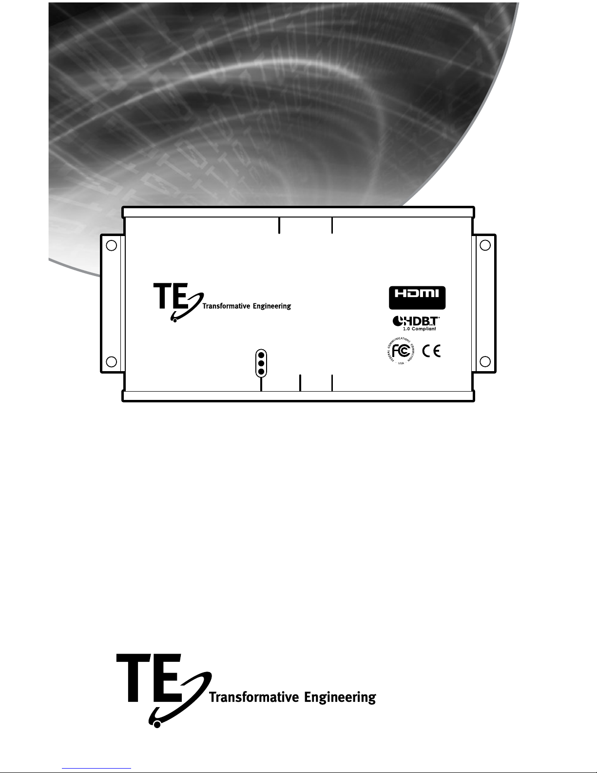
HL-1
HDMI Extender System
Installation Manual
HL-1 RX
HDMI Extender
with HDBaseT-Lite™
HDMI
Out
Power
Link
HDCP
HDBaseT IRDA Out
IRDA
In
Receiver
Page 2

HL-1 Installation Manual
2
Introduction .............................................3
Kit Contents .............................................4
Feature Set .............................................5
Specifications ...........................................6
Transmitter Connections ...................................7
Receiver Connections .....................................8
Connection Diagrams .....................................9
Transmitter Functions ....................................10
Troubleshooting .........................................11
Warranty ..............................................12
Table of Contents
Page 3

HL-1 Installation Manual
3
Introduction
INTRODUCTION
Thank you for purchasing Transformative Engineering’s HL-1 HDMI Extender Kit. This
product incorporates many advanced technologies to accomplish full-function, 1.4a
HDMI compliant extension of the High Definition MultiMedia Interface protocol over
one length of Category 5e/6/7 wire. Among these is the newly certified HDBase-T
technology, licensed here. This unique conversion of HDMI signals provides for the
most reliable, stable and predictable method to transfer all HDMI requirements. More
information on this technology may be found at the HDBase-T website, www.hdbaset.
com. We are proud to be an early Adopter Member of the Alliance.
Proper connection and attention to limitations of this (or any other) product will result
in secure, reliable, and predictable results. The most important variable to success
will depend on wire chosen as the interconnection between our Transmitter and
Receiver. All Category wire is not created equal. It is vital that care is taken at all
times to avoid kinks, crimps, nicks, and other abuse of the wire and jacket. Also, we
highly recommend that all wire be sweep tested before and after installation to insure
full bandwidth is not impaired. A sweep-test generator, such as the Fluke CableIQ
Qualification Tester, or its equivalent, is suggested. Please be sure to specify Category
5e, or better, cable that meets a minimum of 400MHz bandwidth. Typical high-quality
Category 6 cable performs from 550-850 MHz, and Category 7 cable should pass 1GHz
or more.
This HDMI Extender will meet our rated specifications using CAT 5e/6/7 UTP cable. It
will also perform with STP (shielded twisted pair) cable as well. MOST FAILURES OR
INCONSISTENT PERFORMANCE ARE THE RESULT OF INFERIOR WIRE OR IMPROPER
TERMINATIONS. The first step in diagnosing problems with this product should center
on the connection and choice of the wire used.
Please follow the instructions and diagrams shown in this Manual. Any questions
should be directed to your Dealer, Distributor, or to our Technical Department. Our
Contact information is:
Transformative Engineering, Inc.
229 Carnegie Row
Norwood, MA 02062-5000
Telephone: 781-769-6410
Fax: 781-255-0975
Email: [email protected]
Page 4

HL-1 Installation Manual
4
Kit Contents
KIT CONTENTS
(1) HL-1 Transmitter Unit (HL-1TX)
(1) HL-1 Receiving Unit (HL-1RX)
(1) 24V 8.5Watt Power Supply
(4) Nylon “Tie-Wrap” Mounting terminals
(2) Heat-Transfer tape Strips
(4) Metal Mounting Tabs & Screws
(1) User Manual
Page 5

HL-1 Installation Manual
5
Features
FEATURE SET
•HDMI1.4aExtender
•FullHDCPSecurity
•EDIDProtocolIntegrity
•Bi-DirectionalIRPass-ThruwithPowerforActivePickup
•24VPowerSupplyforRobustPerformance
•SinglePowerSupplyforHead-EndPoweringofBothUnits
•ExtrudedAluminumConstructionwithFlexibleMountingOptions
Page 6

HL-1 Installation Manual
6
Specifications
SPECIFICATIONS
Input Signal: HDMI Version 1.0 thru 1.4a
Ethernet (10/100T)
IR Signal – Pass Thru (Industry Compatible)
IR Powered Pickup – Ring (Ground), Tip (Signal),
Sleeve (+12VDC) (see page 8)
Video Formats Supported: 480i/576i/480p/576p/720p/1080i/1080p
Audio Formats Supported: All HDMI Supported Formats, including DTS-HD,
Dolby-HD, DVD-A, Dolby TrueHD, 8-CH LPCM
Output Signal: HDMI Version 1.0 thru 1.4a
Ethernet (10/100T) X 6
IR Signal – Pass Thru (Xantech Compatible)
(See page 8)
Maximum Distance (with CAT6): 70 Meters (230 Feet), @ 1080p
Power Supply X1 (supplied): 24 VDC, 8.5 Watts, Each
Dimensions (Each) 9.0” W x 1.1” H x 3.75” D
Weight: 1.0 Lbs (Each)
Page 7
HL-1 Installation Manual
7
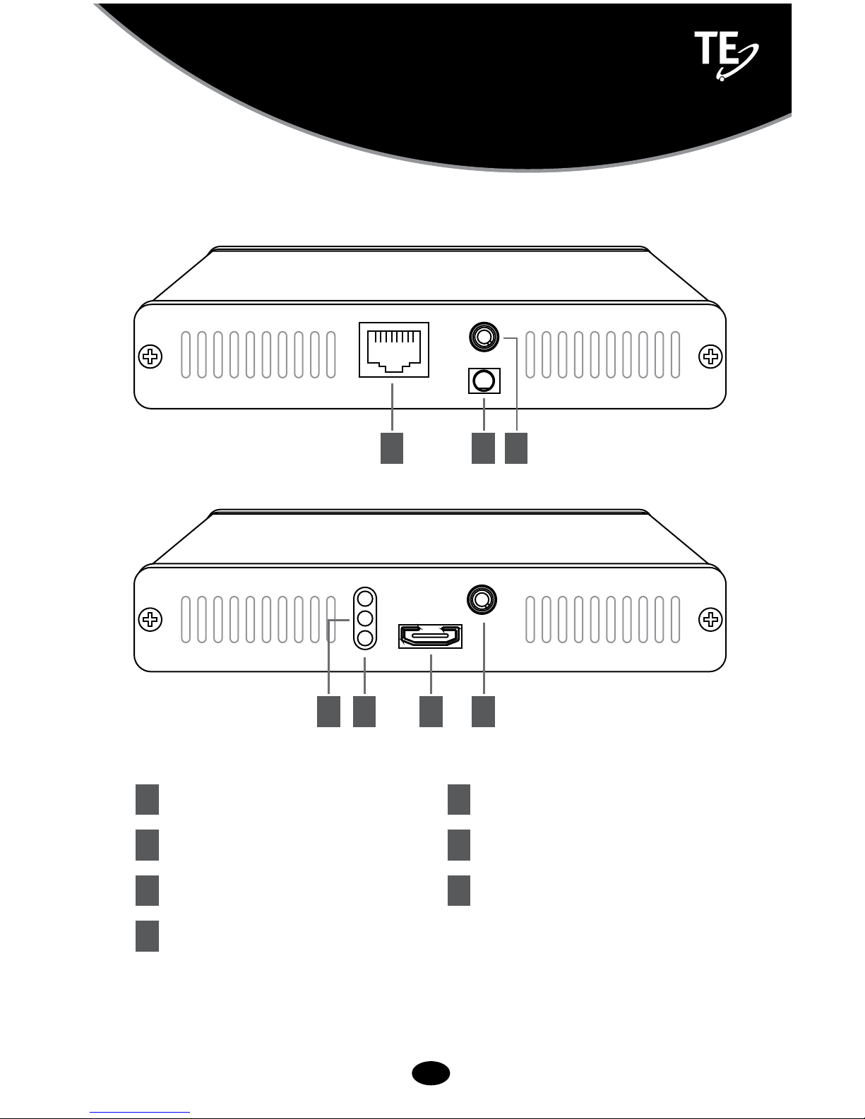
Transmitter Connections
1 HDMI Input
2 HDBase-T Link Connection
3 Power Input
4 IRDA IN
5 IRDA OUT
6 Link Indicators
7 HDCP Indicator
2
6 7
3 5
1 4
TRANSMITTER
Page 8

HL-1 Installation Manual
8
Receiver Connections
1 HDMI Output
2 HDBase-T Link Connection
3 IRDA IN
4 IRDA OUT
5 Link Indicators
6 HDCP Indicator
RECEIVER
2
5 6
4
1 3
Page 9
HL-1 Installation Manual
9
Transmitter Functions
TRANSMITTER FUNCTIONS - See pg 7
1 HDMI Input – Connect this to your HDMI Source – Cable Box, Disc
Player, etc.
2 HDBase-T Link Connection – Connect via Category 5e/6/7
cable to the HL-1 Receiver Unit ONLY. DO NOT CONNECT THIS RJ-45
CONNECTOR TO ETHERNET. DAMAGE TO THIS PRODUCT AND YOUR
NETWORK MAY RESULT. Recommended minimum length is 2 Meters up
to our maximum rated specification of 70 Meters.
3 Power Input – Utilizing the supplied 24V 8.5W supply, connect
at the Transmitter side where indicated. No Power Supply is then
necessary at the Receiver side.
4 IRDA In – Used for connecting to a 12V Powered Infra-Red Pickup
Device via 3-conductor mini-jack, or to IR encoded signal for Pass-Thru
to the IRDA OUT at the Receiver end. Contact TE to purchase an adaptor
if you are using a lower voltage IR device. See Diagram above for
suggested use.
5 IRDA Out – Used for connecting to an Infra-Red Emitter for
controlling a device at this end. The IR Signal would originate from the
Receiver end either from a Powered Pickup or an IR Pass-Thru.
6 Link Indicators – These lights show that communication has been
properly established with the HDBase-T Receiver. No other connections
need be made for these lights to indicate your connection is secure. If
the “POWER” light is not on, you should check that both power supplies
are properly connected.
Page 10

HL-1 Installation Manual
10
Recievers Functions
7 HDCP Indicator – This light shows that a valid HDMI connection has
been made, “handshake” has taken place, and there is a High Definition
Copy Protect flag in operation. Attempts to copy Digital content will not
be allowed. Any connection to a non-compliant Digital copy device will
cause this light to go off, and will result in the loss of signal.
RECEIVER FUNCTIONS - See Page 8
1 HDMI Output – Connect this to your Display device – TV, Projector,
etc. All video signals input to the HDMI Input on the Transmitter will
appear here.
2 HDBase-T Link Connection – Refer to Item (4) above.
3 IRDA In – Used for connecting to a Powered Infra-Red Pickup Device
(Industry compatible) via 3-conductor mini-jack, or to IR encoded signal
for Pass-Thru to the IRDA OUT at the Transmitter end. See Diagram
above for suggested use.
4 IRDA Out – Used for connecting to an Infra-Red Emitter for
controlling a device at this end. The IR Signal would originate from the
Transmitter end either from a Powered Pickup or an IR Pass-Thru.
5 Link Indicator – Refer to Item 9, Above.
6 HDCP Indicator – Refer to Item 10, above
Page 11

HL-1 Installation Manual
11
Troubleshooting
TROUBLESHOOTING
As mentioned previously, most malfunctions can be addressed by
careful examination of the Category cable terminations and suitability
of the UTP cable itself. Once the “Link” lights are on, this system is
operating normally. Lack of function should be traced to a failure in
HDMI interconnection cables or device settings. If all this has been
examined with no resolution of your problem, please contact our
Technical Support Department at 781-769-6410 or via email at: info@
transformativeengineering.com.
Page 12
HL-1 Installation Manual
12
Warranty
WARRANTY
Transformative Engineering, Inc. guarantees this product for Two Years
from your original purchase. We guarantee performance and operation
to published specifications including all parts and labor. We do not
warranty against mis-use or abuse. To obtain warranty service, please
contact our Technical Support Department at 781-769-6410 or via email
at: [email protected].
Transformative Engineering, Inc.
229 Carnegie Row
Norwood, MA 02062-5000
Telephone: 781-769-6410
Fax: 781-255-0975
Email: [email protected]
 Loading...