


RV2VideoProcessor
8-3
RV2Overview
As part of a system is comprised of a machine vision color camera (VGAC), and
a dedicated video processor and collection device (RV2). Video is streamed from
the camera to the RV2 collection device where it is processed and stored. Camera
triggering is precisely synchronized to the collection system (RZ) allowing frame by
frame correlation between video data and other recorded system signals.
A number of methods support robust target tracking including red/green LEDs
mounted on the ZIF-Clip® headstage or limb tracking. Positional information is
available in real-time on the RZ device and can be processed and/or stored. Image
data is stored on dedicated hard drives within the RV2 in DIVX encoded AVI files.
Access to the RV2 storage array can be provided through a LAN connection or
direct connection to a PC.
The RV2 is recommended for use with TDT systems only.
PowerandCommunication
A fiber optic port on the back panel of the RV2 is used to communicate with an RZ
device. The RV2 receives timing pulses from a special DSP (RZDSP-V) and
returns real-time frame and tracking information for further processing and storage.
Communication to the RV2 is provided through a touch screen user interface
independent from the TDT system. Firmware updates for the RV2 interface are
available online through the TDT web server. See “Config” on page 8-15, for more
information.
RV2 Video Processor
8-4 System 3
Snapshots are sent from the RV2 over the network to the PC for laying out regions
using RVMap software. Configuration files are sent from RVMap software to the RV2,
also over the network.
The RV2 contains an integrated switched-mode power supply. The power supply
auto-detects your region’s voltage setting and no further configuration is needed. A
switch located on the back panel of the RV2 is used to enable/disable the power
supply.
SoftwareControl
Software control is implemented with circuit files developed using TDT's RP Visual
Design Studio (RPvdsEx) on the RZ processor through TDT’s OpenEx software
package. A single RPvdsEx macro is provided to configure the RZ to send trigger
information to the RV2 and receive frame and positional information.
See the “RZ Z-Series Processors”, for more information on your RZ processor. For
circuit design techniques and a complete reference of the RPvdsEx circuit
components, see “MultiProcessor Circuit Design” and “Multi-Channel Circuit Design”
in the
RVMap software is used to define regions and tracks for the RV2 search algorithm
and determine what data is returned to the RZ for real-time analysis and/or storage.
See “RVMap Software for RV2” on page 8-21, for more information.
RPvdsEx Manual
.
Triggerin gtheRV2
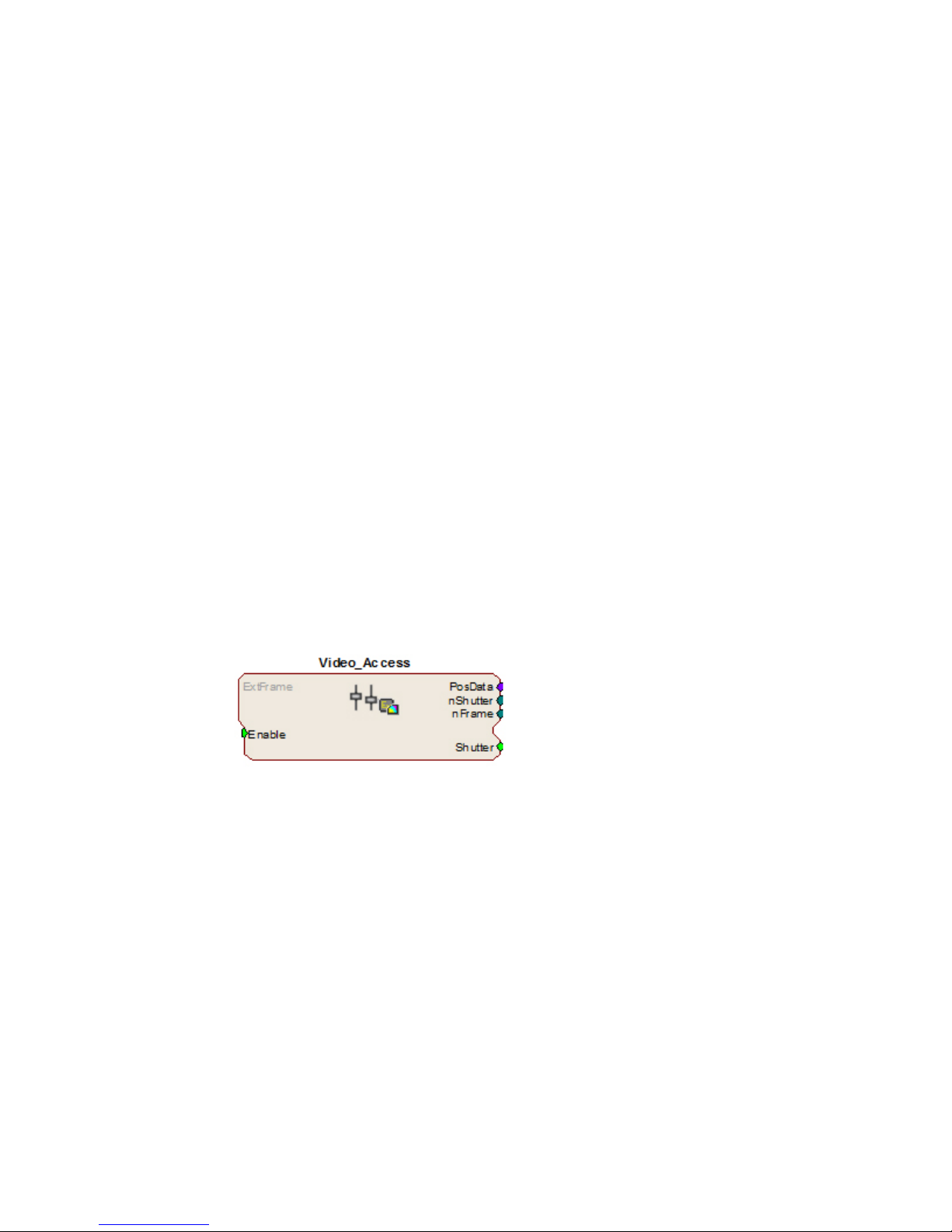
The Video_Access macro is provided for configuring video tracking and must be
added to the circuit file used in OpenEx. The macro has settings for the frame
control, rate, and storage. See the macro internal help for more information.
This macro also requires that the
CoreSweepControl macro is present in
the circuit to handle all circuit timing.
The Video_Access macro stores
timestamps when frame information is
received. The PosData multi-channel
stream contains tracker positions.
Information for up to eight targets can
be returned to the RZ for storage.
RVMap is used to define the targets that
are returned to the RZ. The Video_Access macro must be assigned to the DSP that
is physically connected to the RV2.
The Video_Access macro controls when frame triggers are sent from the RZ to the
RV2. The RV2 receives the trigger, retrieves an image from the camera, adds it into
the video file, performs the tracking algorithm and prepares the tracking data to be
sent to the RZ.
The RV2 waits until the next camera trigger from the RZ before returning the
tracking data from the previous frame to the RZ. This ensures that there is always
enough time to collect an image from the camera and run the tracking algorithm on
it, and greatly reduces the likelihood that a frame is missed due to jitter in the
collection process. However, because of this protection the data received by the RZ
is always off by one frame.
When track data is sent to the RZ it is also written to the tracking.txt file. The
timestamp in the tracking.txt file indicates when the data was collected from the
camera and is relative to when the RV2 began recording.
RV2 Video Processor

System 3 8-5
RecordingSessions
When OpenWorkbench is set to ‘Record’ mode and a Video_Access macro is present
in the circuit, Workbench sends a UDP packet over the network to find RV2s. If
Workbench doesn’t receive a response within five seconds an error message is
displayed and recording begins without video storage. The UDP packet contains the
tank and block name so the RV2 can properly name its files. Once an RV2
responds, OpenEx begins sending frame triggers and recording data. When OpenEx
switches modes to anything other than ‘Record’ a packet is sent to the RV2 to
close the files it is currently writing to and wait for the next recording session.
FrameRate
The maximum frame rate depends on the camera’s exposure setting. This value can
be adjusted using the ‘Lighter’ and ‘Darker’ buttons on the RV2 touch screen
interface. The frame rate is overlaid on the camera image in the Live tab. The
current maximum rate based on the camera settings is displayed when the camera is
in free run mode.
Note: When recording data it is important that the desired frame rate is no greater than
the observed free run frame rate, otherwise frame loss will occur. A lost frame
counter is overlaid on the lower right corner the camera image. To reset this
counter, see the Status tab. A reboot will also reset the lost frame counter.
HardwareRequirements
Basic requirements include a VGAC, an RV2, an RZ equipped with at least one
video fiber optic port, one fiber optic cable for connection between the RV2 and RZ,
the VGAC power cable, one Gigabit Ethernet cable to connect the VGAC to the
RV2, a PC equipped with an Ethernet port or an Ethernet jack connected to a local
area network, and an Ethernet cable.
Setting‐UpYourHardware
Important! Make sure that all cables are connected before powering on the RV2.
RV2toRZ ConnectionDiagram
RV2 Video Processor

8-6 System 3
In the diagram above, a single RZ connects to the RV2. The fiber optic cables are
color coded to prevent wiring errors.
The RV2 Video Processor connects to one RZ processor via orange fiber optic
cables from the back of the RV2 to the dedicated RV2 port on the back of the RZ
(labeled ‘To RV2’).
The gray camera power cable connects the ‘Power-1’ port on the RV2 to the VGAC
camera. A GigE cable connects the ‘Camera-1’ port on the RV2 to the VGAC.
An Ethernet cable connects the ‘Network’ port on the RV2 to either a local area
network or directly to the PC running OpenEx.
Optionally a VGA cable is connected from the ‘Monitor’ port on the RV2 to an
external monitor.
RV2PCand NetworkConnectionDiagram
The diagram above illustrates possible connections from the RV2 to a PC (1) or
network (2). Connect the Ethernet cable to the RV2 port labeled Network.
ConfiguringtheRV2
Default configuration settings allow the RV2 to begin streaming video immediately.
The RV2 supports the DHCP (Dynamic Host Configuration) protocol for automatic
configuration of network parameters. Once connected to an active network, the RV2
will attempt to lease an IP address.
TheDHCPProtocol
DHCP or “Dynamic Host Configuration Protocol” is a protocol used by networked
devices (clients) to obtain various parameters necessary for the clients to operate in
an IP (Internet Protocol) network. By using this protocol, system administration
workload greatly decreases, and devices can be added to the network with minimal
or no manual configuration.
DHCP automates the assignment of IP addresses, subnet masks, default gateway,
and other IP parameters. Three modes for allocating IP addresses exist: Dynamic,
Reserved, and Manual. The RV2 relies on Dynamic mode for its IP configuration. If
no DHCP server responds, enable manual configuration mode with the following static
IP configuration:
RV2 Video Processor

System 3 8-7
IP Address: 10.1.0.42
Netmask: 255.255.255.0
You can configure the IP address manually through the touchscreen interface. See
“To enable manual configuration:” below or “Status” on page 8-14.
Dynamicmode
In dynamic mode a client is provided with a temporary IP address for a given length
of time. The duration is dependent on the server configuration and may range from
several hours to months.
The RV2 will automatically renew the current IP address as needed. This renewal is
used by properly functioning clients to maintain the same IP address throughout their
connection to a network.
AccessingtheRV2
There are two methods provided for accessing the RV2:
• Directly connecting to a PC
• Connection to a local area network
DirectConnectiontoaPC
Direct connection to a PC allows data on the RV2 to be viewed and modified
through the standard Microsoft Windows file sharing protocol.
Important: When using a Static IP, the RV2 Current IP must be set to “Configure Manually”
using the touch screen interface.
To enable manual configuration:
1. Touch the Status Tab and then touch the Current IP field, to display the
Network Configuration window.
2. Touch the Configure Manually check box and click OK to accept the
default value.
UsingWindows7
To access the RV2 file system through a PC, running Windows 7:
3. You will have to configure the PC TCP/IP settings. Open Control Panel
then double-click Network and Sharing Center.
4. Click the desired connection link (this is usually a Local Area Connection).
5. In the status dialog, click the Properties button.
RV2 Video Processor

8-8 System 3
6. In the item list, select Internet Protocol (TCP/IP) or if there are multiples,
select Internet Protocol (TCP/IPv4).
7. Click the Properties button.
8. Select Use the following IP address and enter these values:
IP address: 10.1.0.x, where x can be any value from 1 to 254 except 42.
Subnet mask: 255.255.255.0
Default gateway: Leave empty
9. Click OK. The RV2 can now be accessed by the PC.
10. Obtain the RV2 device address.
a. Press the Live tab on the RV2 interface.
b. The device address is displayed at the top of the page to the right of
Device Name field.
11. Enter the device address as shown in a windows address bar to access the
RV2 file system.
Typically, the path \\RV2-XXXX\ is used to access the RV2 storage array,
where XXXX is the device serial number, but the name should be verified on
the Live tab.
12. Access the files on the RV2 by reading or writing.
WARNING! Do not attempt to write to the RV2 at any time while
data is actively recording Doing so may corrupt data currently being stored.
RV2 Video Processor

System 3 8-9
UsingWindowsXP
To access the RV2 file system through a PC:
1. You will have to configure the PC TCP/IP settings. Open Control Panel
then double-click Network Connections.
2. Right-click the desired connection (this is usually a Local Area Connection)
and select Properties.
3. Select Internet Protocol (TCP/IP) or if there are multiples, select Internet
Protocol (TCP/IPv4).
4. Click the Properties button.
5. Select Use the following IP address and enter these values:
IP address: 10.1.0.x, where x can be any value from 1 to 254 except 42.
Subnet mask: 255.255.255.0
Default gateway: Leave empty
6. Click OK. The RV2 can now be accessed by the PC.
7. Obtain the RV2 device address.
a. Press the Live tab on the RV2 interface.
b. The device address is displayed at the top of the page to the right of
8. Enter the device address as shown in a windows address bar to access the
RV2 file system.
Typically, the path \\RV2-XXXX\ is used to access the RV2 storage array,
where XXXX is the device serial number, but the name should be verified on
the Live tab.
9. Access the files on the RV2 by reading or writing.
Device Name field.
RV2 Video Processor

8-10 System 3
WARNING! Do not attempt to write to the RV2 at any time while
data is actively recording. Doing so may corrupt data currently being stored.
ConnectingThroughaNetwork
Connection to a local area network also allows data to be viewed and modified
through the standard Microsoft Windows file sharing protocol from any PC connected
to the same network as the RV2.
To access the RV2 file system through a network:
1. DHCP must be enabled on the network in order to access the RV2. If
DHCP is disabled or not supported, you can connect the RV2 directly to a
PC.
2. Obtain the RV2 device address.
a. Press the Status tab on the RV2 interface.
b. The device address is displayed in the middle of the page just under the
Fan Speeds.
3. Enter the device address in a windows address bar to access the RV2 file
system.
4. Access the files on the RV2 by reading or writing.
WARNING! Do not attempt to write to the RV2 storage array at any
time while data is actively streaming. Doing so may corrupt data currently
being stored.
FindingtheMACAddress
In some labs, the network administrator may require RV2 users to provide the
device’s MAC address.
To determine the address, follow the instructions below:
1. On the touchscreen interface, press the Status tab. Press in the Current IP
field.
2. A Network Configuration dialog is opened and the MAC address is displayed
at the bottom of the pop-up window.
Note: If the RV2 does not automatically identify on a network, you can force it to reset its
IP address by unplugging the Ethernet cable the plugging it in again.
RV2StorageFormat
The RV2 has three main storage folders – configs, recordings, snapshots.
Configs: All of the rvm configuration files sent from RVMap are stored
here.
Recordings: For each recording, a new folder is created that contains the avi
RV2 Video Processor
file, the rvm used for that recording and a text file
(tracking.txt) that contains the results of the tracking algorithm.
The tracking.txt file contains a list of frame numbers and tracked
point information for each frame. The total number of points may
exceed the 8 tracked target limit of the RZ2

System 3 8-11
Snapshots: Holds JPG images from when the Snapshot button was pressed
on the Live tab of the RV2 interface.
NamingConvention
When connected to an active network, TDT’s OpenEx software sends information to
the RV2 via a broadcast UDP packet allowing it to properly name the video file
recorded on the RV2. This allows you to easily match up the video with data stored
in the tank. For example, if you are recording for the event Vid0 in Block-3 of
DemoTank2 the RV2 will store in the following location and format:
\recordings\DemoTank2\Block-3\DemoTank-Block-3_Vid0.avi
Without the OpenEx network information the RV2 falls back to the default data
format:
\recordings\YYYY-MM-DD hh_mm_ss\YYYY-MM-DD hh_mm_ss.avi
Note: The snapshots always store in the default format.
\snapshots\YYYY-MM-DD hh_mm_ss.jpg
RV2Features
PowerButton
A power button located on the front plate of the RV2 is used to turn the device on
and off. Prior to powering on/off, the device will enter a brief boot/shutdown period.
Important! Only power the RV2 down when it is not actively recording a video. Failure to do
so may result in the RV2 performing a file system check during the next boot
process and possible data loss.
Note: If the RV2 becomes unresponsive and fails to shutdown normally, you can shut the
device down by holding the power button for longer than five seconds. This will force
the device to shutdown. After a forced shutdown, the RV2 may perform a file system
check.
LCDTo uchScreen
The LCD touch screen allows navigation through the RV2 interface. To make a
selection, gently press the touch screen on the desired item.
Interface
The interface reports information and allows configuration of available options. A
selection tab located on the right-side of the screen allows the user to select
between the available pages. To navigate to the desired window, press the
corresponding tab on the right side of the LCD screen.
RV2 Video Processor

8-12 System 3
Live
The Live tab shows the current image captured by the camera, allows changes to
the camera settings, and allows the user to choose the current tracking configuration.
Device Name: The NetBIOS name of the device.
Firmware Version: The currently installed firmware version number. This is
useful for identifying the current firmware version and
also to verify that a recent firmware update has been
installed. See “Config” on page 8-15, for more
information on updating the firmware.
Current Config: A dropdown list of all available configurations. Tap a
configuration to select it.
AutoOnce: Tells the camera to perform its built-in auto-adjustment
of exposure, gain and white balance.
Lighter/Darker: Adjusts the exposure time longer and shorter,
respectively.
Full Screen: Displays the camera image over the entire screen.
Tapping on the full screen image returns the interface to
normal.
Resolution: (v1.6b & above) A dropdown list at the bottom of the
screen controls the camera resolution (640x480 or
320x240). Lower the resolution to achieve a higher
frame count.
Manual Control: Enables the Snapshot, Track LEDs and Record buttons.
You cannot record from OpenEx while the RV2 is in
Manual mode. When in Manual Control mode, tap the
Manual Control button to disable Manual Control.
Snapshot: Copies the current camera image to a JPG file on the
Track LEDs: Applies the tracking specification in the currently selected
RV2 Video Processor
RV2 hard drive, into the snapshots folder.
configuration file to the live camera feed. If colored
targets are tracked, dots will appear in the image where
the algorithm is finding targets. Use this mode to

System 3 8-13
preview the efficiency of the tracking algorithm and then
modify the configuration and/or camera settings if
needed.
Record: Performs a manual recording. Since the camera is in
free-run mode the frame rate will be maximized. Tap
Record again to stop recording.
Color: Switches between color and black-and-white modes.
Playback
The Playback tab provides a list of video files currently stored on the RV2. Videos
may be reviewed through this interface. The video’s length is displayed, in time or
in frames, as well as the current position.
Current Video: A dropdown list containing all video files on the RV2.
Tap a video name to select it.
Play: Begin playing the currently selected video. Tap again to
pause playback. To restart the video, you must select a
different video and then select the original video.
As Frames/As Time: Switch the Video Stats units from time to frames.
Synchronized playback: When tank data is accessed by a TDT application (such
as OpenExplorer or OpenScope) the application will
detect epoch event names that begin with ‘Vid’. When
the TDT application retrieves data from that epoch, the
TDT application will send a UDP packet containing the
tank name, block name and current value of that epoch
(which corresponds to the frame number). An RV2 on
the network will receive the packet, open the
corresponding video file (if it exists) and jump to that
frame. The RV2 must be on the Playback tab for this
functionality.
Rerun tracking algorithm: While playback is occurring on the RV2, the rvm file in
the same directory as the avi file on the RV2 file
system is used to run the tracking algorithm and overlay
the results on the video image.
RV2 Video Processor

8-14 System 3
Status
The Status tab provides system information such as processor usage rates, core
temperatures, fan speeds, device IP address, array reformat progress, memory buffer
allocation, and communication errors. Log information can also be retrieved from this
tab.
System: Displays important system status information.
Processor Usage: Displays the current percent usage for each processor
core.
Core Temperatures (F): Displays the current processor core temperatures
measured in Fahrenheit. The text will turn yellow or
red if the processor gets too hot. This can occur if
there is an issue with the heatsink or internal fans.
When this happens the RV2 will sound a warning
and should be shut down immediately.
Fan Speeds (RPM): Displays the approximate rpm for all three fans located
inside of the RV2.
Current IP: Displays the IP address currently assigned to the RV2.
Press to display Network Configuration Window.
RV2 Video Processor
Configure Manually - select to enable manual
configuration and make fields editable.

System 3 8-15
Storage Array: Displays information about the state of the current
storage array.
Active and mounted: Storage array is available and ready to store data.
Active and not mounted:A support storage array is available but is not
configured to store data.
Array was not found!: The system did not detect a supported storage array.
Progress bar: Displays progress for various processes which run on the
RV2 including:
Reformatting: When reformatting a storage array, the progress
completed (%) as well as the estimated
amount of time remaining is displayed.
Resyncing: If a mirrored array type has been formatted, the
progress completed (%) as well as the
estimated amount of time remaining for the
Resync process is displayed.
File System Check:The RV2 will perform a file system check during the
boot process once every 30 boots. This ensures
the integrity of the storage array and file system.
If the RV2 is performing a file system check,
the progress completed (%) and estimated
amount of time remaining is displayed. During
this time the Playback tab will be disabled and
the RV2 cannot be triggered for storage.
Memory Usage: Displays current and maximum memory (RAM) usage
since last reboot
Memory Usage: High Water Mark displays the most memory used by the
system since last reboot. Current Size displays the
currently used memory. Total System (free total)
indicates how much memory is available vs how
much total memory the system has.
Clear Lost Counter: Resets the lost frame counter.
View Log Window: A log stores relevant messages and any communication
errors encountered while the RV2 is in use. Click to
open and view the log window. The log.txt file can be
copied from the storage array for transfer to a PC.
Note: Individual comments can be saved as well. Use a drag gesture to highlight the
desired comment(s) and click Save to write the selection to the log.txt file.
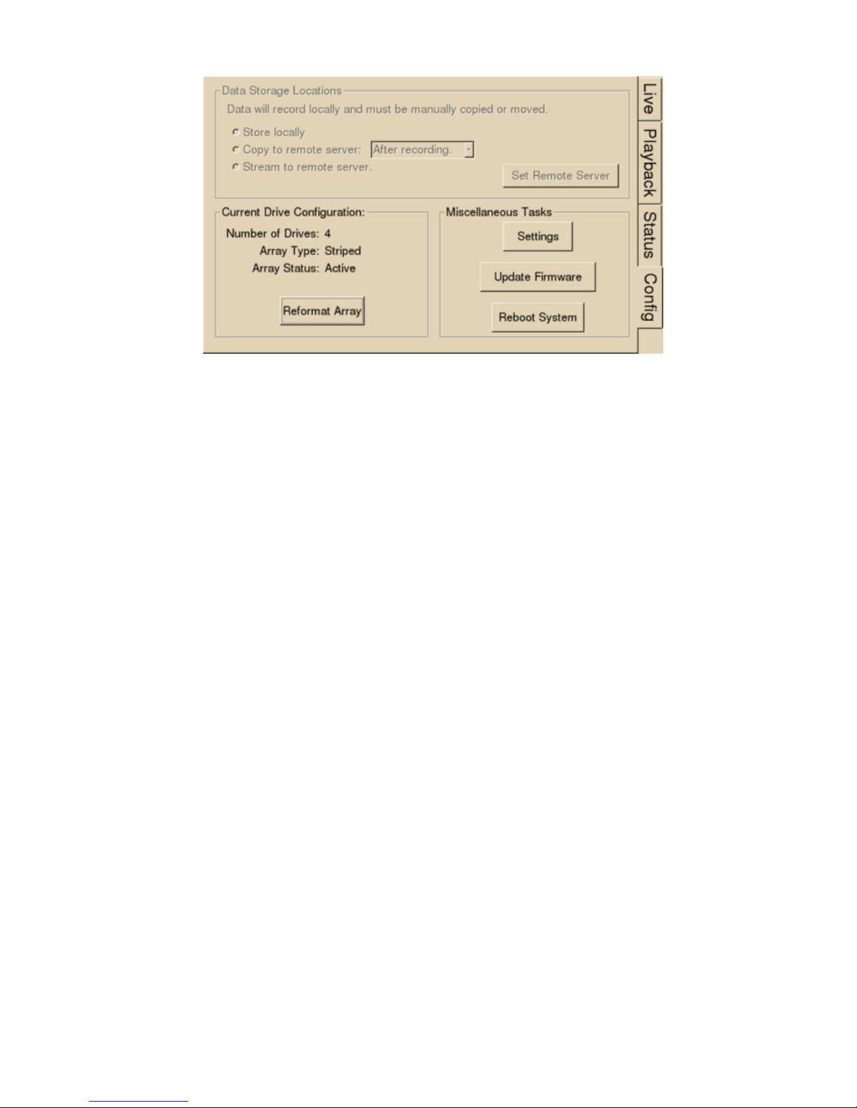
Config
The Config tab provides options for reformatting the currently installed storage array,
updating the RV2 firmware, and rebooting the system.
RV2 Video Processor
8-16 System 3
Data Storage Locations: Not currently implemented.
Current Drive Configuration:Displays information about the currently installed data
drives.
Number of Drives: Displays the number of drives currently installed.
Array Type: Displays the currently configured array type and the
status of the drives.
Striped: Array type is currently configured as striped.
Mirrored(UU): Array type is currently configured as mirrored. A U
indicates that a drive is up and running. A
_ indicates a drive failure.
Missing: No array type is detected.
Array Status: Displays the current status of the array.
Preparing: Storage array is currently being reformatted.
Resyncing: Storage array is being reformatted as a mirrored array
and is currently resyncing the mirrored partitions.
N/A: Storage array is not detected.
Active: Storage array is detected and configured.
Reformat Array: Press to prompt the reformat array dialog. This dialog
will ask for confirmation as well as the desired array
type: Striped or Mirrored. Reformatting an array will
erase all data contained in the array. Note: When
reformatting an array, the interface may become
temporarily unresponsive.
Miscellaneous Tasks: Provides options for updating the current RV2 firmware
and rebooting the system.
Settings: Press to display the settings window, then set date and
Update Firmware: Press to update the RV2 firmware. Firmware is
RV2 Video Processor
time and select unit of measure for temperature.
downloaded from the TDT server and automatically
installed on the RV2. Connection to a DHCP enabled
network that has Internet connectivity is required to
retrieve any updates.

System 3 8-17
Reboot System: Click to reboot the system.
DeviceStatusLEDs
The device status LEDs report streaming or network activity. The following tables
display the status LED indicators.
Video Status Information
Off No video camera is detected.
Lit Video camera has been found
Network Status Information
Off No network traffic detected.
Lit Network traffic is present and detected on the RV2.
Storage Status Information
Off No storage access to the RV2 is detected.
Lit Storage access to the RV2 is in progress
EthernetPorts
Two Ethernet ports are provided on the back panel, Video and Network.
Camera-1 The Camera-1 port connects directly to the Ethernet port on the
VGAC. Important! The cable connecting the RV2 to the VGAC
MUST support gigabit Ethernet (e.g. Cat 5e, Cat 6).
Network The Network port allows connections to either a PC or local
area network via a standard Ethernet cable. The RV2 supports
automatic DHCP protocol.
PowerPort
A 9-pin serial port is provided on the back panel, labeled Power. This port is
connected to a special cable that provides power to the VGAC using the special gray
cable provided with the system.
VGAPort
A VGA port is provided on the back panel, labeled Monitor. This port can be
connected to an external monitor that will show the current camera image or a video
that is being played in the Playback tab.
Important!: The external monitor must be connected before the RV2 is powered on.
USB2.0Port
This port is currently not in use.
RV2 Video Processor

8-18 System 3
Tech nicalSpecifications
Processing Cores
Storage Array Size
System RAM
Number of Video Inputs
Frame Rates (typical with
standard VCAC)
Video File Format
VGAC Specifications:
Camera type
CCD sensor size
Aperture (f/#)
Focal Length
Resolution
4
2 Terabytes
2 GB
1
640x480 color -- 40 FPS
320x240 color -- 100 FPS (firmware v1.6b and above)
DIVX encoded AVI
CCD
1/3”
F1.4
4.0 – 8.0 mm
8-bit per channel (24-bit total)
Auto Exposure
Features
Field of View (degrees)
Spatial Resolution (minutes)
Resolutions
Cables Provided
Auto Gain
Auto White balance
vertical = 57.2, horizontal = 70.6
vertical = 16.3', horizontal = 15.7'
640x480 color
320x240 color
Power: 30 ft (9 m)
Ethernet: 30 ft (9 m)
Troubleshooting
The following section provides examples and solutions to some of the errors that
could be encountered while using the RV2 Video Tracker.
DeviceWillNotPowerUp
Check the position of the power supply switch. If set to the “O” position the power
supply is disabled. To enable, simply ensure that the switch is in the “1” position
and attempt to power on the RV2. If the device does not power up after verifying
that the power supply is enabled contact TDT.
RV2 Video Processor

System 3 8-19
Can’tAccesstheRV2StorageArray
Check the Ethernet cable connection to ensure that the RV2 is connected to a
network or PC using the Network Ethernet port located on the back panel of the
RV2. If the Ethernet cable is connected to the Video Ethernet port, network traffic
will cause the Network status LED to light up. See “Setting-Up Your Hardware” on
page 8-5, for connection diagrams.
If you are attempting to access the RV2 through a network, ensure that the server
supports DHCP. If not, the RV2 will default to its static IP address (10.1.0.42). If
you encounter this issue, see “Direct Connection to a PC” on page 8-7, for
information on how to access the RV2 using a direct connection to a PC.
RV2InterfaceBecomesSloworUnresponsive
Every thirtieth time the RV2 is booted up, it performs a disk check. The length of
time required to perform this check depends on how much video data is currently
stored on the RV2. During this time, the Playback tab will be grayed out and you
will be unable to record to the RV2. The Status tab. TDT recommends removing
unnecessary data remaining on the storage array.
RV2IsNotCorrectlyNamingDataFolders
When connected to an active network, TDT’s OpenEx software sends information to
the RV2 via a broadcast UDP packet allowing it to properly name the video files
stored on the RV2. If the RV2 is powered on before connecting the necessary
network cables it may default to the basic naming format. Power off the RV2,
connect all the necessary cables then power the RV.
RV2 Video Processor

8-20 System 3
RV2 Video Processor
 Loading...