


Siemensstraße 18
84051 Essenbach
Tel:
+49 8703 929-00
Fax:
+49 8703 929-201
Web
www.tdt.de
E-Mail:
support@tdt.de
C1500
–
Series
C1550
–
Series
C2000
–
Series
M3000
–
Series
G5000
–
Series
L3000
–
L5000
DocID:
Manual C-, M-, G-, L-Series
Rev.:
8.54.0 – 01.03.2016 – SH

C-M-G Series
Manual
© TDT GmbH
Imprint
Seite 2 von 136
Manual for C-, M-, G- and L-Series
Imprint
Liability
The compilation of text and illustrations for this manual has been undertaken with the greatest
care. However, errors and omissions cannot be completely ruled out. The pub-lisher accepts
absolutely no responsibility for incorrect information. We reserve the right to make changes to
this documentation and the products described herein at any time with-out prior notice.
Contact
Our document department will be pleased to assist you should you experience problems with
this document
Copyright
TDT GmbH
Siemensstraße 18
84051 Essenbach
Tel.: +49 (8703) 929-00
Fax: +49 (8703) 929-201
Web: www.tdt.de
Email: support@tdt.de
We wish you success and enjoyment
Your TDT Team

C-M-G Series
Manual
© TDT GmbH
Contents
Seite 3 von 136
Contents
Imprint 2
Contents 3
1 First Steps 10
1.1 Commissioning 10
1.2 Package contents 10
1.2.1 C1500 / C1500 10
1.2.2 C2000 10
1.2.3 M3000 / L3000 10
1.2.4 G5000 / L5000 11
1.3 Unit description and Port Allocation 11
1.3.1 C1500, C1550 & C2000 11
1.3.1.1 Front Side C-Series 11
1.3.1.1.1 LED Standard configuration 12
1.3.1.1.2 C1500h 12
1.3.1.1.3 C1500hw 12
1.3.1.1.4 C1550 and C2000 13
1.3.1.2 Rear Side C-Series 14
1.3.2 M3000 15
1.3.3 G5000 16
1.3.4 Serial number 16
1.4 Access Data 17
1.5 How to connect to the Router? 18
1.5.1 Webinterface 18
1.5.2 Command Line Interface (CLI) 19
1.5.3 Serial Connection 19
2 Webinterface 22
3 Command Line Interface - CLI 23
4 System Confuguration 24
4.1 Bootup and Shutdown 24
4.2 Configuration Handling 24
4.3 Event-Handler 24
4.3.1 Event-Handler 24
4.3.1.1 Health Checker 25
4.3.1.2 ICMP Checker 25
4.3.1.3 Example script 25
4.3.2 SMS-Handler 26

C-M-G Series
Manual
© TDT GmbH
Contents
Seite 4 von 136
4.3.2.1 Supported Status Commands 27
4.4 Firmware Update 28
4.5 LED Assignment (C-Series only) 28
4.5.1 Ethernet 28
4.5.2 WLAN 28
4.5.3 PPP and WWAN Interface 29
4.5.4 GSM Options 29
4.5.5 Connection Manager 30
4.5.6 IPSec connection 30
4.5.7 Certificate 30
4.5.8 SIM Card 30
4.5.9 Flashing frequencies 30
4.6 Push Button Settings 30
4.6.1 Push Button Actions 31
4.6.2 Push Button Assignments 31
4.7 Scheduled Cron Jobs 31
4.7.1 Create a new scheduled cron job 32
4.7.2 Create a new environment variable 33
4.7.3 Control user access to cron jobs 33
4.8 System Time 33
4.9 Time Synchronisation 33
4.10 Webmin Configuration 34
4.10.1 IP Access Control 34
4.10.2 Port and Address 34
4.10.3 Logging 34
4.10.4 Language 35
4.10.5 Authentication 35
4.11 Webmin Users 36
5 Network Configuration 37
5.1 BIND DNS Server (M3000, G5000 only) 37
5.2 Certificate Management 37
5.2.1 Import-PKCS#12 38
5.3 Connection Management 38
5.3.1 Connection-Manager 38
5.3.1.1 Connection-Dial-Entry 38
5.3.1.1.1 Inhibit 39
5.3.1.1.2 Interface- and Ping-Checker 39
5.3.1.1.3 Connection overview 39
5.3.1.1.4 Add Connection (Connection-Dial-Entry Parameter) 40
5.3.1.2 Logical Subordinated Connections 43
5.3.1.2.1 Inhibit 43
5.3.1.2.2 Logical-Interface- und Ping-Checker 44
5.3.1.2.3 Add Connection (Connection-Logical-Entry Parameter) 44
5.3.2 Static Connections 45
5.4 DHCP Server 45

C-M-G Series
Manual
© TDT GmbH
Contents
Seite 5 von 136
5.5 DNS Server Update 46
5.6 DNSmasq 47
5.7 Dynamic DNS Update 47
5.8 IPSec VPN 48
5.8.1 Global Settings 48
5.8.1.1 Configure IPSec-Interface-Mappings 49
5.8.1.1 Configure Miscellaneous Settings 49
5.8.2 Debug & Log 49
5.8.3 Connection Defaults 50
5.8.3.1 Global Settings 50
5.8.3.2 Phase1(ISAKMP) Settings 51
5.8.3.2.1 PSK-Settings 51
5.8.3.2.2 Certificate-Settings 52
5.8.3.2.3 XAuth-Client-Settings 52
5.8.3.2.4 XAuth-Server-Settings 52
5.8.3.2.5 IKE Settings 53
5.8.3.2.6 Rekeying Settings 53
5.8.3.3 Phase2 Settings 53
5.8.4 Keys 54
5.9 Linux Firewall (IPtables) 54
5.9.1 Tables 54
5.9.2 Chains 55
5.9.3 Targets 56
5.9.4 Linux Firewall Menu 56
5.9.5 Create a new rule 57
5.9.5.1 Chain and action details 57
5.9.5.2 Condition details 58
5.9.6 Example: Setup IP Forwarding 60
5.10 Network Configuration 61
5.10.1 Network Interfaces 61
5.10.1.1 Bridge Settings 62
5.10.1.2 Tunnel Settings 62
5.10.2 Routing and Gateways 63
5.10.3 DNS Client 64
5.10.4 Host Addresses 64
5.11 OpenVPN 65
5.11.1 Add new server/client 65
5.11.2 Edit existing peer 65
5.12 PPP 68
5.12.1 PPP Interfaces 68
5.12.1.1 Basic PPP configuration for interface ppp# 68
5.12.1.1.1 ISDN PPP Interface Parameter 68
5.12.1.1.2 ISDN Dial-In PPP Interface Parameter 69
5.12.1.1.3 PPPoE Interface Parameter 69
5.12.1.1.4 UMTS/GPRS PPP Interface Parameter 70
5.12.1.2 Advanced PPP configuration for interface ppp# 70
5.12.1.2.1 ISDN PPP Interface Parameter 70
5.12.1.2.2 ISDN Dial-In PPP Interface Parameter 71

C-M-G Series
Manual
© TDT GmbH
Contents
Seite 6 von 136
5.12.1.2.3 PPPoE Interface Parameter 71
5.12.1.2.4 UMTS/GPRS PPP Interface Parameter 72
5.12.1.2.5 General PPP settings 72
5.12.1.2.6 Logging Parameters 73
5.12.1.2.7 Networking Parameters 73
5.12.1.2.8 Authentication Parameters 73
5.12.1.2.9 Compression Parameters 74
5.12.1.3 Parameters for interface pppX when used in Static Connections 75
5.12.2 PPP Accounts 75
5.12.2.1 Create new PPP CHAP/PAP account 75
5.13 Postfix Configuration (M3000, G5000 only) 76
5.14 QoS Control 76
5.14.1 Outgoing Interfaces 76
5.14.1.1 Interface parameters 76
5.14.1.2 Root Qdisc Parameters 76
5.14.1.2.1 TBF (Token Bucket Filter) 76
5.14.1.2.2 SFQ (Stochastic Fairness Queueing) 77
5.14.1.2.3 BFIFO (Bytes First In First Out) 77
5.14.1.2.4 PFIFO Packet First In First Out 77
5.14.1.2.5 DSMARK 77
5.14.1.2.6 HTB (Hierarchical Token Bucket) 78
5.14.1.2.7 PRIO (Filter) 78
5.14.1.2.8 PRIO (Priomap) 78
5.14.2 Incoming Interfaces 78
5.14.2.1 Interface parameters 78
5.14.3 Interface Statistics 78
5.15 SNMP 79
5.15.1 Access Control 79
5.15.2 Sysinfo Setup 79
5.15.3 Trap Control 80
5.15.3.1 SNMP Create New Trap Control 80
5.15.4 (Sub)Agent Configurations 80
5.15.4.1 Common Settings 80
5.15.4.2 Monitor Running Processes 80
5.15.4.2.1 SNMP Agent Create Process Monitor 80
5.15.4.3 Monitor Disk Space 81
5.15.4.4 Monitor File Sizes 81
5.15.4.5 Monitor Load Averag 81
5.16 SSH Server 82
5.16.1 Authentication 82
5.16.2 Networking 83
5.16.3 Access Control 83
5.16.4 Miscellaneous Options 83
5.16.5 Client Host Options 84
5.16.6 User SSH Key Setup 84
5.17 SSL Tunnels 85
5.18 VRRP / Loadbalancer * 86
5.18.1 Functionality VRRP 86
5.18.1.1 Behaviour of the VRRP in Backup Status 86

C-M-G Series
Manual
© TDT GmbH
Contents
Seite 7 von 136
5.18.1.2 Behaviour of the VRRP-Routers in Master-Status 86
5.18.2 Global Definitions 86
5.18.3 VRRP Instances 87
5.18.3.1 Add VRRP nstance 87
5.18.4 VRRP Synchronization Groups 88
5.18.4.1 VRRP Create New Sync. Group 89
5.18.5 Load Balancer Global Settings 89
5.18.6 Load Balancer Real Servers 89
5.18.7 Load Balancer Virtual Servers 90
5.19 WLAN 92
5.19.1 General settings 93
5.19.2 WPA/WPA2-PSK related settings 93
5.19.3 N-Standard settings (High Throughput Capabilities) 93
5.19.4 Advanced settings 94
5.19.5 WEP related settings 94
5.19.6 WPA/WPA2-EAP settings 94
5.19.6.1 Radius Client Settings 94
5.19.6.2 Internal EAP Server Einstellungen 95
5.19.6.2.1 EAP User Einstellungen 95
5.19.7 MAC Address Filtering 95
5.20 WWAN 96
6 The Diagnose Menu 97
6.1 Connection Manager 97
6.2 Distribution Information 97
6.3 GSM Modem State 97
6.4 Load Balancer 97
6.4.1 Load Balancer Statistics 97
6.4.2 Load Balancer Connections 98
6.5 Log File Rotation 98
6.6 PPP 98
6.7 Running Processes 98
6.8 System Information 99
6.9 System Logs 99
6.10 Webmin Actions Log 99
7 The Permanent Save Menu 100
7.1 Save Config 100
7.2 Save System to USB (only M- und G-Series) 100
8 Save and restore configuration 101
8.1 Save configuration 101
8.1.1 Webinterface 101
8.1.2 CLI 102
8.2 Restore configuration 102

C-M-G Series
Manual
© TDT GmbH
Contents
Seite 8 von 136
8.2.1 Webinterface 102
8.2.2 CLI 103
9 Restoration of the delivery status 104
9.1 C-Series 104
9.2 M3000 / G5000 / L-Series 104
10 Firmware Update 105
10.1 Webinterface 105
10.2 CLI 106
11 CLI Commands 107
11.1 Top level - TDT(CLI) 107
11.1.1 Configuration menu - TDT(CLI/configuration) 108
11.1.1.1 Network Configuration menu - TDT(CLI/configuration/network) 108
11.1.1.1.1 Network Interface menu - TDT(CLI/configuration/network/interface) 108
11.1.1.1.2 Connection-Manager - TDT(CLI/configuration/network/dialup) 113
11.1.1.1.3 SNMP Einstellungen - TDT(CLI/configuration/network/snmp) 116
11.1.1.1.4 NTP Settings - TDT(CLI/configuration/network/ntp) 121
11.1.1.2 General Settings - TDT(CLI/configuration/general) 122
11.1.2 Status menu - TDT(CLI/status) 122
11.1.2.1 Show menu - TDT(CLI/status/show) 124
12 Hardware 125
12.1 C-Series 125
12.1.1 Technical Data 125
12.1.1.1 C1500xx 125
12.1.1.2 C1550xxx 125
12.1.1.3 ELW Router C1550lw 126
12.1.2 Hardware Modules 126
12.1.3 DB9 / RS232 PIN- Allocation (DTE/V.24) 127
12.2 M3000 127
12.2.1 Supportet UMTS / GPRS Cards 127
12.2.2 Layout of the DSL/ISDN Y-Cable 128
12.2.3 Ethernet 4 Port Card 128
12.2.4 NT - TE Switching of the HST Saphir III ML DUAL ISDN Karte (Optional) 129
12.3 G5000 129
12.3.1 ISDN PRI 129
12.3.1.1 Pin allocation of the RJ45 PRI connector 130
13 Overview of Important Data 131
13.1 C-, M-, G- and L-Series default 131
13.1.1 Change password 132
13.1.1.1 Webinterface 132
13.1.1.2 Commandline user root 132
13.1.2 Operating temperature 133
13.1.3 Declaration of Conformity 133

C-M-G Series
Manual
© TDT GmbH
Contents
Seite 9 von 136
13.2 System specific data 133
13.2.1 C-Router with radio modem 133
13.2.1.1 GPS 134
13.2.1.1.1 Read GPS Data 134
13.2.1.1.2 Send GPS Data 135
13.2.2 C-Router with WLAN module 135
13.3 Software 135
14 Link Overview 136
14.1 General Links 136
14.2 Important Informationen 136
14.3 Used Software 136
14.4 Further Links 136

C-M-G Series
Manual
© TDT GmbH
Chapter 1: First Steps
Seite 10 von 136
1 First Steps
1.1 Commissioning
Open the transport packaging carefully and check the content.
Connect the delivered unit using supplied power supply or power cable to a 230V mains supply.
Connect your network with the delivered CAT5 network cable to the eth1 port of the router.
Note
Before commencing commissioning remove the router from the packing and let it stand for at
least 1 hour until it has reached room temperature to prevent damage due to condensed
water.
Due to transport, plug-in cards could have become loose. Please check the proper condition
of these cards before attempting to operate the unit.
1.2 Package contents
1.2.1 C1500 / C1500
C1500 or C1550
Power supply (12V DC / 1,8 A) with European plug
CAT5 LAN cable
Associated antennas depending on version
Manual on USB-Stick
1.2.2 C2000
C1500
Power cable
CAT5 LAN cable
Associated antennas depending on version
Manual on USB-Stick
1.2.3 M3000 / L3000
M3000
Power cable
CAT5 LAN cable
ISDN/DSL cable depending on version
1 USB Init-Stick (for Factory Reset)
Manual on USB-Stick

C-M-G Series
Manual
© TDT GmbH
Chapter 1: First Steps
Seite 11 von 136
1.2.4 G5000 / L5000
G5000
Power cable
CAT5 LAN cable
Additional cables depending on Hardware configuration (e.g. Serial, ISDN, etc.)
1 USB Init-Stick (for Factory Reset)
Manual on USB-Stick
1.3 Unit description and Port Allocation
1.3.1 C1500, C1550 & C2000
1.3.1.1 Front Side C-Series
The front of the C1500 includes three LED status indicators, C1550 and C2000 are equipped with eight
additional status LEDs. Furthermore a reset button and a SIM slot are located on the routers front side.
Figure 1: Front side C1500
Figure 2: Front side C1550
Figure 3: Front side C2000

C-M-G Series
Manual
© TDT GmbH
Chapter 1: First Steps
Seite 12 von 136
Description
Power - L2
Status indicator LEDs
Status 1 - 8
additional status indicator LEDs on C1550 and C2000
Reset-Button
Mode of operation see chapter Fehler! Verweisquelle konnte nicht gefunden werden.
SIM 1
Card slot for SIM1
SIM 2
Card slot for SIM2, C2000 only
1.3.1.1.1 LED Standard configuration
The C-Series LEDs are free programmable (see 4.5 LED Assignment (C-Series only)), only the Power
LED is fixed and cannot be changed. Depending on router type and equipment the LEDs are preset.
LED
Status
Beschreibung
Power
off:
Unit is without power / switched off
on:
Operational mode
low flashing:
Boot process
fast flashing:
Remote access via SSH active
1.3.1.1.2 C1500h
LED
Wert
Status
Beschreibung
L1
PPP3_UP_DOWN_DATA
off:
PPP3 Link down
on:
PPP3 Link up
flashing:
data transfer on PPP3 (RX + TX)
L2
WWAN0_UP_DOWN_DATA
equals radio connection
off:
WWAN0 Link down
on:
WWAN0 Link up
flashing:
data transfer on WWAN0
(RX + TX)
1.3.1.1.3 C1500hw
LED
Wert
Status
Beschreibung
L1
WLAN0_ON_OFF_CONNECT
off:
WLAN0 inactive
on:
WLAN0 active
flashing:
at least one connection initiated
L2
WWAN0_UP_DOWN_DATA
equals radio connection
off:
WWAN0 Link down
on:
WWAN0 Link up
flashing:
data transfer on WWAN0
(RX + TX)

C-M-G Series
Manual
© TDT GmbH
Chapter 1: First Steps
Seite 13 von 136
1.3.1.1.4 C1550 and C2000
LED
Wert
Status
Beschreibung
L1
WLAN0_ON_OFF_CONNECT
off:
WLAN0 inactive
on:
WLAN0 active
flashing:
at least one connection initiated
L2
ETH0_UP_DOWN_DATA
off:
ETH0 Link down
on:
ETH0 Link up
flashing:
data transfer on ETH0 (RX + TX)
LED
Wert
Status
Beschreibung
Status 1
WWAN0_UP_DOWN_DATA
equals radio connection
off:
WWAN0 Link down
on:
WWAN0 Link up
flashing:
data transfer on WWAN0
(RX + TX)
Status 2
PPP2_UP_DOWN_DATA
off:
PPP2 Link down
on:
PPP2 Link up
flashing:
data transfer on PPP2 (RX + TX)
Status 3
PPP3_UP_DOWN_DATA
equals DSL
off:
PPP3 Link down
on:
PPP3 Link up
flashing:
data transfer on PPP3 (RX + TX)
Status 4
ACTIVE_SIM_CARD
off:
no SIM in use
on:
SIM1 in use
flashing:
SIM2 in use
Status 5
GSM0_CONNECT_STATUS
off:
no connection
low flashing:
2G connection (GPRS or EDGE)
fast flashing:
3G connection (UMTS/WCDMA or
HSPA)
on:
4G connection (LTE)
Status 6
GSM0_SIGNAL1
off:
no radio reception (0%)
on:
radio reception 1% - 33%
Status 7
GSM0_SIGNAL2
on:
radio reception 34% - 66%
Status 8
GSM0_SIGNAL3
on:
radio reception 67% - 100%

C-M-G Series
Manual
© TDT GmbH
Chapter 1: First Steps
Seite 14 von 136
1.3.1.2 Rear Side C-Series
Figure 4: Rear side C1500
Figure 5: Rear side C1550
Figure 6: Rear side C2000
Connector
Description
3G/4G
SMA socket for radio antenna
ISDN
RJ45 connector for ISDN
L1
ISDN Status LED active ISDN Layer 1 connection
B Rx/Tx
ISDN Status LED on: B chanal connection established
flashing: ISDN data transfer
WiFi AUX
RP-SMA socket for a second WLAN antenna used for N standard
DSL
RJ45 connector for the integrated DSL modem with status indicators
Green flashing: DSL synchronisation is running
Green + Orange on: DSL sync is finnished
Orange flashing: DSL data transfer
Serial 0
9-pole RS-232 console port (speed: 38400 (8N1))
3G/4G AUX
SMA socket for a second radio antenna
C-M-G Series
Manual
© TDT GmbH
Chapter 1: First Steps
Seite 15 von 136
Connector
Description
ETH1
10/100BaseT interface (at C1550 with an integrated 4 Port Switch) with an
automatic speed recognition at its disposal as well as an automatic recognition
of the cable (1:1 or cross over)
ETH0
10/100BaseT interface with an automatic speed recognition at its disposal as
well as an automatic recognition of the cable (1:1 or cross over)
Note
The C1500 and C1550 routers can be supplied with power by the
eth0 interface using »passive Power over Ethernet«.
Therefore a PoE Converter is required.
USB
2 USB 2.0 Ports for external Hardware
Power
Socket for the power connection using the supplied power supply
WiFi
RP-SMA socket for the primary WLAN antenna
1.3.2 M3000
The M3000 is designed for a 19 Zoll Server Rack and takes the height of one rack unit. On the front of the
M3000 the following connectors and switches can be found (from left to right):
Connector
Description
Power
Pushbutton to swich on the Router
LED
Status indicator LEDs
USB
2 USB 2.0 Ports for external Hardware
COM
9-pole RS-232 console port (speed: 38400 (8N1))
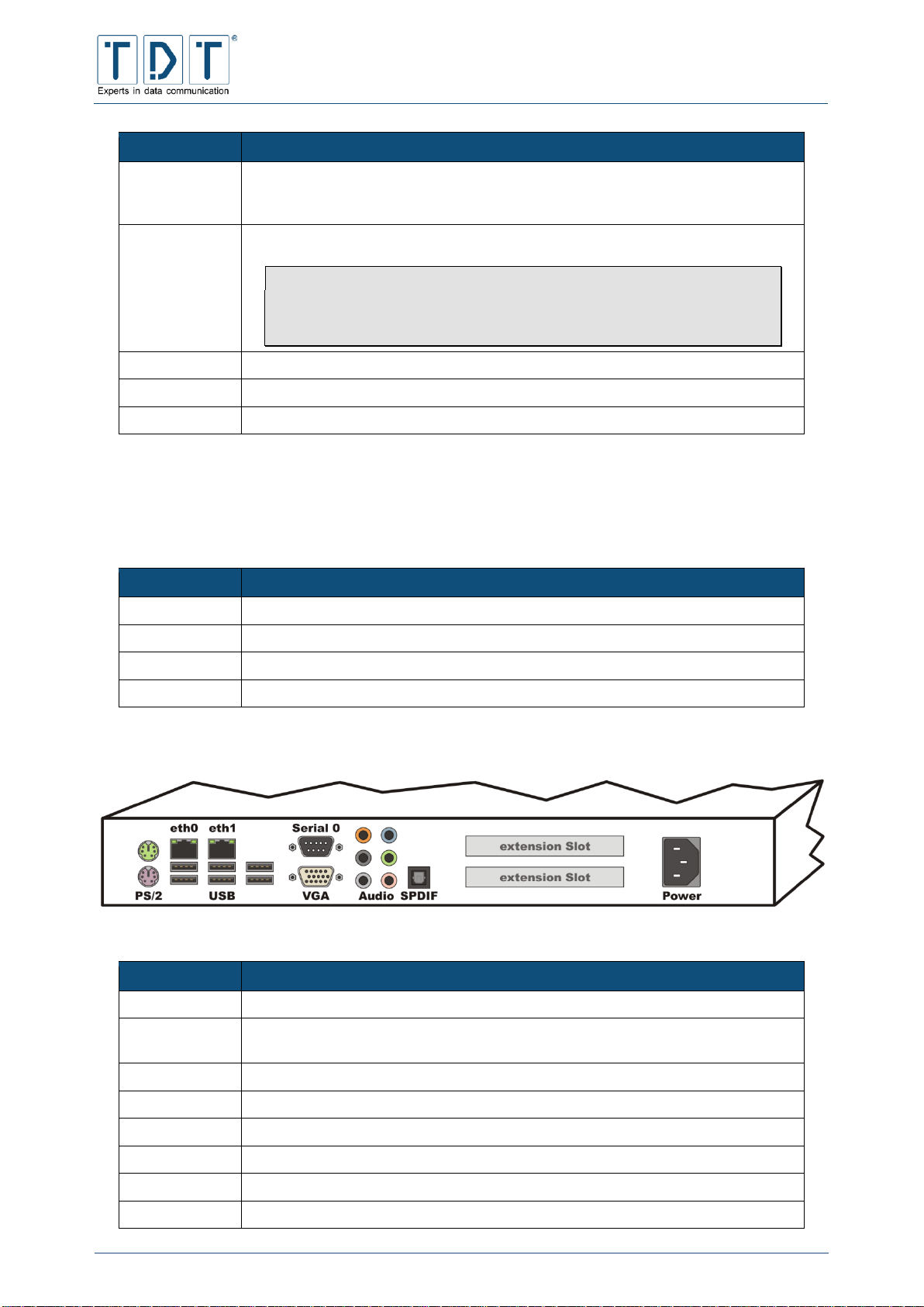
On the rear of the M3000 the following relevant operational connections can be found:
Figure 7: Rear side M3000
Connector
Description
PS/2
Connector for Mouse and Keyboard
eth0 & eth1
10/100/1000BaseT interface with an automatic speed recognition at its disposal
as well as an automatic recognition of the cable (1:1 or cross over)
USB
6 USB 2.0 Ports for external Hardware
Serial 0
9-pole RS-232 console port (speed: 38400 (8N1))
VGA
Monitor connector
Audio & SPDIF
Audio connectors
extension Slot
Depending on hardware configuration (e.g. DSL, ISDN, ethernet port(s))
Power
IEC connector C14 for the power supply with 230V AC

C-M-G Series
Manual
© TDT GmbH
Chapter 1: First Steps
Seite 16 von 136
1.3.3 G5000
The G5000 is designed for a 19 Zoll Server Rack and takes the height of two rack units. Under the front
flap the following connectors and switches can be found (from left to right):
Connector
Description
Power
Rocker button to swich on the Router
Reset
Rocker button to restart the Router
LED
Status indicator LEDs
USB
2 USB 2.0 Ports for external Hardware
PS/2
Mouse/Keyboard connection via Y-adapter
At the rear side of the G5000 there are all necessary connectors:
Figure 8: Rear side G5000
Anschluss
Beschreibung
Power
IEC connector C14 for the power supply with 230V AC
ON/OFF
Rocker switch to switch on the power supply
extension Slot
Depending on hardware of the G5000 (e.g. DSL, ISDN, Ethernet Port(s))
ttyS0, ttyS1
9-pole RS-232 console port (speed: 38400 (8N1))
eth0, eth1,
eth10
10/100/1000BaseT interface with an automatic speed recognition at its disposal
as well as an automatic recognition of the cable (1:1 or cross over)
VGA
Monitor connector
USB
2 USB 2.0 Ports for external Hardware
1.3.4 Serial number
The serial number is located on the bottom side and on the delivery note. This is uniquely assigned to
each device. Please keep the serial number ready at support/service and repair requests.
Note
It is recommended that serial number is documented if the unit is mounted and therefore
serial number no longer be readable.

C-M-G Series
Manual
© TDT GmbH
Chapter 1: First Steps
Seite 17 von 136
1.4 Access Data
In all C-, M-, L- and G-units the following specified data are preset as standard.
Default LAN network
IP adress for eth1
192.168.0.50
Subnet mask for eth1
255.255.255.0
Default WAN interface
IP adress for eth0
10.99.99.99
Subnet mask for eth0
255.255.255.0
Default WLAN configuration
for untis with WLAN
module
IP adress for wlan0
172.16.0.50
Subnet mask for wlan0
255.255.255.0
SSID
TDT-AP
Pre Shared Key (ASCII)
tdt-Router
Channel
1 (2412 MHz)
Encryption
WPA+WPA2-PSK
(AES/CCMP + TKIP)
Webinterface
Access via SSL
https://<interface IP>
Username
tdt
Password
tdt
SSH / CLI
SSH Port
22
CLI Port
2000
Username
root
Password
tdt
Serial Port (RS232)
Speed
38400 bit/s
Data bits
8
Parity
keine
Stop bits
1
Note
For connection to a PC please use a null modem
cable. (not included in delivery)
IMPORTANT!
For safety reasons please change the preset webinterface and SSH-access
passwords! (see 13.1.1 Change password)
Change also the Pre Shared Key on units with WLAN module!

C-M-G Series
Manual
© TDT GmbH
Chapter 1: First Steps
Seite 18 von 136
1.5 How to connect to the Router?
To configure the router you can use the webinterface (for simple configuration via web browser) or the
TDT CLI (Command Line Interface). You are able to connect to the Router via SSH or serial using the
COM port.
Note
To be able to connect to the router via LAN, you need to have a PC which is in the same
TCP/IP network as the router. In default you need an IP adress from the 192.168.0.0/255
range (e.g. 192.168.0.1) and the 255.255.255.0 subnet.
1.5.1 Webinterface
Type the routers IP adress in the adress field of your web browser. In default configuration the IP of the
eth1 port is set to 192.168.0.50.
Because the Webinterface is only accessable via SSL, the syntax https:// must be included in front of
the IP adress.
Example:
https://192.168.0.50
In the login windows of the configuration level the username and corresponding password must be
entered.
Figure 9: For security reasons the characters of the password is displayed as asterisks

C-M-G Series
Manual
© TDT GmbH
Chapter 1: First Steps
Seite 19 von 136
In delivery status Username and Password are preset to tdt and tdt.
There is a download-link for the user manual on the top right corner of the logon page.
1.5.2 Command Line Interface (CLI)
You can connect to your router via SSH, with a SSH client like the free implementation »PuTTY«
(http://www.chiark.greenend.org.uk/~sgtatham/putty).
First navigate to Terminal > Keyboard and set „The Backspace key“ to parameter Control-H.
Figure 10: PuTTY Configuration - Keybord settings
Then navigate back to Session and establish a SSH connection to the Routers IP, using the CLI Port. In
delivery status the eth0 IP adresse is preset to 192.168.0.50 and the CLI Port is 2000.
Figure 11: PuTTY Configuration for a CLI connection
1.5.3 Serial Connection
Note
To be able to establish a serial connection a Null modem cable (not included in delivery) is
needed.

C-M-G Series
Manual
© TDT GmbH
Chapter 1: First Steps
Seite 20 von 136
Connect the Null modem cable to the routers COM port (RS-232) and the serial port of your local
maschine.
Choose e.g. »PuTTY« for dial in.
First set Connection type: to Serial.
Figure 12: change to serial
Then navigate to Terminal > Keyboard and set The Backspace key to parameter Control-H.
Figure 13: PuTTY Configuration Keybord Einstellung
Next navigate to Connection > Serial, type your PCs used COM port (e.g. COM1) in the Serial
line to connect box and set Speed (baud) to 38400. Choose Flow controll None and
establish the connection.
Figure 14: PuTTY Configuration for serial connection

C-M-G Series
Manual
© TDT GmbH
Chapter 1: First Steps
Seite 21 von 136
Press [Enter] in the new opend window to go to the Login screen. Sign in using the SSH Access data.
(for security reasons the characters of the password won’t be displayed). Open the Command Line
Interface by typing the command cli.
Figure 15: Router login

C-M-G Series
Manual
© TDT GmbH
Chapter 2: Webinterface
Seite 22 von 136
2 Webinterface
The Webinterface is a browser-based application that cooperates with every updated web browser. This
graphical user interface is one of the easiest ways to administrate and supervise the C-, M-, G- and
L-Series routers remotely from own workplace.
For better usability, we seperated it into 4 menues called »System«, »Networking«, »Diagnose« and
»Permanent Save«. After log in you will find these items on the left-hand side of the website as well as a
»Manual« Download Link, the »Reboot System« and the »Logout« button.
A click onto a menue item will expand or reduce the menue.
The expanded menues will display the routers configuration items.
Figure 16: Home page and navigation with Networking menu expanded
Important!
Run Permanent Save > Save Config to store your current configuration
including all changes and adjustments permanently on the router
otherwise these changes will be lost after next reboot or power cycle.

C-M-G Series
Manual
© TDT GmbH
Chapter 3: Command Line Interface - CLI
Seite 23 von 136
3 Command Line Interface - CLI
Another easy way to configure your routers is the command line interface (CLI) developed by TDT.
Within the CLI you can display the current configuration and check several parameters on the easiest
way. In addition, a kind of batch configuration is possible, where you can easily paste configurations from
a text file.
The instructions of the current, activated menu levels can be displayed by entering a question mark (see
Example1). Additional information and help about a command can be displayed by entering a question
mark behind the command(see Example2).
Example1:
TDT(CLI): ?
configuration *enter configuration mode
status *Status information
write Save Configuration Permanent to
Flash
save Save Configuration as Textfile
to /tmp
load Load Configuration from
Textfile in /tmp and overwrite all existing configuration
include Include Configuration from
Textfile in /tmp and add it to existing configuration
reboot Reboot System
shutdown Shutdown System
halt Shutdown System immediately
exit Exit CLI
Example2:
TDT(CLI/configuration/general): prompt ?
prompt: TDT
OK
The command quit will terminate the CLI from every menue level.
Important!
To save changes permanently, it is always necessary to complete a Perma-
nent Save in top level with the instruction write, otherwise the settings
will be lost in the case that the router performs a reboot or due to power-
fail.
See chapter 11 CLI Commands for a list of possible commands.

C-M-G Series
Manual
© TDT GmbH
Chapter 4: System Confuguration
Seite 24 von 136
4 System Confuguration
In Webinterfaces System menu the basic router settings can be changed.
Furthermore many configuration tasks can be done using the CLI. This methode is suitable to reduze
traffic and for the case that only low bandwidth is available.
4.1 Bootup and Shutdown
In the Bootup and Shutdown menu the running and stopped services are displayed. By marking one or a
number of the selection boxes the preferred services can be started or stopped by clicking the
corresponding button underneath the table.
On the bottom of the page there are two additional buttons providing the ability to restart or power off the
router. Furthermore the running system will be displayed, and you are able to change the default bootup
system (System 1 or System 2).
CLI-equivalent:
In CLI’s top level the commands reboot and shutdown may be used to perform router reboot
or shutdown.
4.2 Configuration Handling
Using the Configuration Handling, stored router configuration files can be reinstated or respectively the
current router configuration files can be stored. During saving process the whole /etc directory will be
stored into flash.
With the integrated upload and download function, you are able to upload configuration files from your
computer or download files from the router, which have been created with the Configuration Handling
previously. (see chapter 8 Save and restore configuration)
4.3 Event-Handler
4.3.1 Event-Handler
The Event-Handler provides the possibility to react on a certain event with a predefined command (script).
Therefore the router pings a target host and starts the predefined script depending on the result. The
intervals between the pings and the minimum threshold for activating the script can be defined precisely.
Command
Description
Activate process-Monitoring
Activate/deactivate Event-Handlers process-monitoring
Interval for processMonitoring
Intervall in seconds for process-monitoring
Action to perform on
missing process
Action to perform if eventhandler process is not running
Activate Event-Handler
Activate/deactivate Event-Handler

C-M-G Series
Manual
© TDT GmbH
Chapter 4: System Confuguration
Seite 25 von 136
Note
In order to create a userdefined script the event has to be saved using the [Create] button.
4.3.1.1 Health Checker
Command
Description
Health Check Target
Target host
Health Check Port
Target port
Health Check Interval
Interval between the pings in seconds
Health Check Interval if one
request failed
Interval between pings, if one ping has failed
Health Check Timeout
Timeout for Health Check Ping (Default: 60 seconds)
Maximum Failed Requests
Maximum number of failed pings before the script is executetd
(Default: 1)
Action on success
Action to take on success
Action on failure
Action to take on failure
4.3.1.2 ICMP Checker
Command
Description
ICMP Check Target
Target host
ICMP Check Interval
Interval between pings in seconds
ICMP Check Interval if one
request failed
Interval between pings, if one ping failed
ICMP Check Timeout
Timeout for ICMP Check Ping (Default: 5 seconds)
ICMP Check packet-size
ICMP Check packet size in bytes (Default: 4 bytes)
Maximum Failed Requests
Maximum number of failed pings before the script is executetd
(Default: 3)
ICMP Check Interface
Select interface to check in the dropdown menu
Action on success
Action to take on success
Action on failure
Action to take on failure
4.3.1.3 Example script
If the target is reachable, the DNAT rule of the firewall is deleted, all requests go to IP address
192.168.100.51 with port 23966.
#OK script
#!/bin/sh
export
PATH=/usr/local/sbin:/usr/local/bin:/bin:/usr/bin:/sbin:/usr/sbin:/o
pt/TDT/bin
logger "deleting Firewall-Rule for DNAT..."

C-M-G Series
Manual
© TDT GmbH
Chapter 4: System Confuguration
Seite 26 von 136
iptables -D OUTPUT -t nat -d 192.168.100.51 -dport 23966 -j DNAT -to-destination 192.168.100.102:23966
logger DONE
If the target is not reachable, a DNAT rule is added, which redirects all requests to the IP address
192.168.100.102 and port 23966.
#Bad script
#!/bin/sh
export
PATH=/usr/local/sbin:/usr/local/bin:/bin:/usr/bin:/sbin:/usr/sbin:/o
pt/TDT/bin
logger "adding Firewall-Rule for DNAT..."
iptables -A OUTPUT -t nat -d 192.168.100.51 -dport 23966 -j DNAT -to-destination 192.168.100.102:23966
logger DONE
4.3.2 SMS-Handler
The SMS handler provides the ability to send control commands via SMS to the router. Therefore a
SIM-card has to be inserted in one of the simcard slots.
Note
In case a data connection is established the currently active simcard slot is beeing used for
SMS-Handler.
If no data connection is active the interal simcard slot (SIM2) will be used as default. (see
13.2.1 C-Router with radio modem).
In addition single or multiple phone number can be defined from which the router can be controlled. SMS
messages from other numbers will be ignored.
Command
Description
Accept SMS from phonenumbers
Allowed phone numbers with country code but without
leading zero can be defined here. Please seperate multiple
numbers by comma.
Example
4917xxxxxxxx,4916xxxxxxxx
SMS command-separator
For sending multiple commands in one SMS message a
control character is neccessary and can be defined here.
(Default: CR,LF)
Send SMS reply
This parameter defines if the router will send a
response/confirmation message by sms.
Note
For receive status requests via sms this
parameter must be set to Yes.
Activate SMS-Handler
Activates/deactivates the SMS-Handler Service

C-M-G Series
Manual
© TDT GmbH
Chapter 4: System Confuguration
Seite 27 von 136
All CLI configuration commands expect status requests are supported. Check 11 CLI Commands for
more details.
Example1
General prompt <prompt>
Example2
Ethernet-eth0 ip 1.2.3.4
4.3.2.1 Supported Status Commands
Note
Not all status requests are supported yet.
This list contains all available status commands that can be send via SMS.
Command
Description
modemstat
Lists status of GPRS-Module
modem_signal
Shows signal quality
modem_reg
Show registration status to mobile network
modem_net
Show provider network the router is attached to (e.g. T-D1)
modem_lac
Show local area code
modem_cell
Show ID of current cell
get_ip
Provides IP address of the currently active mobile connection
ppp_disc <interface>
Disconnect a PPP interface
connection_deact
Deactivate a Connection-Entry
pppstat <interface>
Shows the status of a PPP connection
ifconfig
Show interface-status
sastat
Show IPSec-SA-status
uptime
Show router uptime
id
Show firmware version
arp
Show/Delete ARP-entries
ping
Ping host (five ping packets will be sent)
traceroute
Traceroute a host (waittime 10 sec)
delete_sa <SA-name>
Delete IPSec-SA
date
Show system date and time
cpu
Show CPU- and memory-Utilization
write
Save configuration permanent to flashdisk

C-M-G Series
Manual
© TDT GmbH
Chapter 4: System Confuguration
Seite 28 von 136
Command
Description
reboot
Reboot system
4.4 Firmware Update
On this page you will find the Firmware Update, which provides the ability to update the units’ firmware.
See chapter 10 Firmware Update for the how to proceede.
4.5 LED Assignment (C-Series only)
In the LED Assignment menu you can view and change the configuration of the LEDs on the front of the
router. In this case the following commands can be defined.
Note
replace n with interface/modem number
4.5.1 Ethernet
Value
Status
Description
ETHn_UP_DOWN
off
ETHn link down
on
ETHn link up
ETHn_DATA
off
no data transfer on ETHn
on
data transfer on ETHn (RX + TX)
ETHn_UP_DOWN_DATA
off
ETHn Link down
on
ETHn Link up
flashing
data transfer on ETHn (RX + TX)
4.5.2 WLAN
Value
Status
Description
WLANn_ON_OFF
off
WLANn inactive
on
WLANn activated
WLANn_CONNECT
off
no WLAN connections initiated
on
at least one WLAN connection initiated
WLANn_ON_OFF_CONNECT
off
WLANn inactive
on
WLANn activated
flashing
at least one WLAN connection initiated

C-M-G Series
Manual
© TDT GmbH
Chapter 4: System Confuguration
Seite 29 von 136
4.5.3 PPP and WWAN Interface
Value
Status
Description
PPPn_UP_DOWN
off
PPPn link down
on
PPPn link up
PPPn_DATA
off
no data transfer on PPPn
on
data transfer on PPPn (RX + TX)
PPPn_UP_DOWN_DATA
off
PPPn Link down
on
PPPn Link up
flashing
data transfer on PPPn (RX + TX)
WWANn_UP_DOWN
off
WWANn Link down
on
WWANn Link up
WWANn_DATA
off
no data transfer WWANn
on
data transfer on WWANn (RX + TX)
WWANn_UP_DOWN_DATA
off
WWANn Link down
on
WWANn Link up
flashing
data transfer on WWANn (RX + TX)
4.5.4 GSM Options
Value
Status
Description
GSMn_CONNECT_STATUS
off
no connection
low flashing
2G connection (GPRS or EDGE)
fast flashing
3G connection (UMTS/WCDMA or HSPA)
on
4G connection (LTE)
GSMn_REG_STATUS
off
not registered to a GSM network
on
Registered to GSM network
GSMn_GPRS_REG_ROAM
off
not registered
on
registered, home network
flashing
registered, roaming network
GSMn_SIGNAL1
1 LED only
off
no radio reception (0%)
low flashing
1 - 25 %
medium flashing
26 - 50 %
fast flashing
51 - 75 %
very fast flashing
76 - 99 %
on
full radio reception (100%)
GSMn_SIGNALm
2 or more LEDs
on/off
signalstrenght depending on number of
configured LEDs
(m == Signal LED number)

C-M-G Series
Manual
© TDT GmbH
Chapter 4: System Confuguration
Seite 30 von 136
4.5.5 Connection Manager
Value
Status
Description
CM_n_CONNECTED (NAME)
off
Connection-Managers Entry n not
connected
on
Entry n connected
flashing
Entry n in initialization sequence
4.5.6 IPSec connection
Value
Status
Description
IPSEC_name_CONNECTED
off
IPSec connection name not established
on
IPSec connection name established
4.5.7 Certificate
Value
Status
Description
CERT_name_STATUS
off
Certificate name not available or damaged
on
Certificate name available and valid
flashing
Certificate name available but expired
4.5.8 SIM Card
Value
Status
Description
ACTIVE_SIM_CARD
off
no SIM in use
on
SIM1 in use
flashing
SIM2 in use
4.5.9 Flashing frequencies
Status
Frequenzy
low flashing:
2000 ms
medium flashing:
500 ms
fast flashing:
100 ms
very fast flashing:
30 ms
4.6 Push Button Settings
Due to the 'Reset-Button' a lot of functions can be run on the C-series, for example a change on the
provider or simply resetting the router to its delivery status.
C-M-G Series
Manual
© TDT GmbH
Chapter 4: System Confuguration
Seite 31 von 136
Depending on how long the reset button is being held down it will have different effects after releasing.
While pushing the Reset-Button the LED's Power, L1 and L2 will flash one after another. Given the
combination of the LEDs' flashing the release of the button will have impact in different ways.
The delivery status' functions are as followed:
Action
Active LED
Time
Function
1st action
Power
0 - 3 seconds
Rebooting the C1500.
2nd action
Power, L1
4 - 14 seconds
C1500 is turning off.
3rd action
Power, L1, L2
≥ 15 seconds
Recovery of the delivery status (factory reset)
and rebooting the router.
You can individually configure the actions 1st action and 2nd action by switching to »Push
Button Assignments«.
4.6.1 Push Button Actions
First a particular action needs to be created. It can be done by navigating through System > Push
Button Settings > Push Button Actions.
Command
Description
Description
Name, brief description of the defined action.
Associated action
Linux-command or selected script.
Note
Command should always be defined within double
apostrophes.
4.6.2 Push Button Assignments
By using the module »Push Button Assignments« the defined actions in »Push Button Actions« can be
assigned to the actions 1st action and 2nd action.
The 3rd action is not configurable and always results in a factory reset.
IMPORTANT!
Any changes will only take effect after the next reboot of the router!
4.7 Scheduled Cron Jobs
The Scheduled Cron Jobs menu contains a compilation of cronjobs. The list contains the cronjobs for
each user and their execution status.

C-M-G Series
Manual
© TDT GmbH
Chapter 4: System Confuguration
Seite 32 von 136
4.7.1 Create a new scheduled cron job
With the Create a new scheduled cron job link a comprehensive formula for entering new
cronjobs is opened, the details as well as the timing of the events can be defined here.
Note
When a cronjob is used to activate (deactivate) a task, it must not be forgotten to create a
cronjob to deactivate (activate) the task.
Command
Description
Execute cron job as
User, under which the cronjob should be executed
Active
Cronjob is activated/deactivated
Command
Unix command to be executed
For example:
/etc/sysconfig/network-devices/ifup wlan0
Input to command
If the task was successfully started, the command entered
here ist passed over during runtime
When to execute
Simple schedule:
The task can be executed at fixed times. Possible values are
hourly, daily (at midnight), weekly (on Sunday), monthly (on
the 1st), yearly (on 1st Jan.) when the system boots
Times and dates selected below:
The task is executed at the selected time
Minutes, Hours, Days, Months,
Weekdays
All: the cronjob will be executed at all the listed entries
Selected: the cronjob will only be executed at selected listed
entries.
In the following example the cronjob task will be used to activate the WiFi interface every Monday to
Friday at 07.00 am.

C-M-G Series
Manual
© TDT GmbH
Chapter 4: System Confuguration
Seite 33 von 136
Figure 17: Example configuration - start WLAN
4.7.2 Create a new environment variable
Enviroment variables for cronjobs can be defined here.
4.7.3 Control user access to cron jobs
Using access control users can be specified wich are permittet to create and start cron jobs. Three
different options are available.
Command
Description
Allow all users
Access to cron jobs is granted for all users
Allow only listed users
Only listed users are allowed to create and execute cron jobs
Deny only listed users
Access to con jobs is not granted for users listed here.
4.8 System Time
System and hardware time can be set within this module. Furthermore the Time zone and a Network
Time Protokoll Server (NTP Server) can be defined here.
4.9 Time Synchronisation
The NTP - Time Synchronisation menu provides the possibility to enter a Network Time Protocol Server.
For example the NTP Server of the Physikalisch-Technisches Bundesanstalt (ptbtime1.ptb.de) can be
used. Note that the entry of a domain name will not work until the DNS task has been configured and is
started.

C-M-G Series
Manual
© TDT GmbH
Chapter 4: System Confuguration
Seite 34 von 136
On all C-Router units with equipped GPS you may be able to sync the time via the integrated GPS
receiver.
This function only works if the Router time devitates not more than 4 hours. This time server uses the
pseudo IP address 127.127.20.0.
4.10 Webmin Configuration
Using the Webmin Configuration menu different settings can be defined such as IP address access
control, language, etc.
4.10.1 IP Access Control
In the IP Access Control menu you have the possibility to restrict acces to the Webmin menu.
Command
Description
Allow from all addresses
(Default)
Allows all IP addresses access to the Webmin interface
Only allow from listed
addresses
Allows Webmin interface access only from those IP addresses
listed in the adjacent window
Deny from listed addresses
Allows Webmin interface access to all IP addresses apart from
those listed in the adjacent window
Resolve hostnames on
every request
Initiates a manually entered host name with every new access.
This is necessary for example when the remote station only has a
dynamic DNS name and hence can change its IP address
4.10.2 Port and Address
In the Port and Address menu you can enter the IP address and the port number the Webmin interface
should listen to.
Command
Description
Listen on IP address
(Default)
Provided the router has several IP addresses you can enter a
number of IP addresses here, which the Webmin interface should
monitor
Listen on port
Here you enter the port number, which the Webmin interface
should use. The port number 10000 is entered as default.
Listen for broadcasts on
UDP port
Here you can enter the UDP broadcast port number, which the
Webmin interface should use. The Port number 10000 is entered
as default
4.10.3 Logging
Webmin can be configured to write a protocol file for page enquiries in standard CLF protocol file format.
When logging is activated, you can choose whether IP addresses or host names should be recorded and
how often the protocol file should be deleted. When protocolling is activated Webmin writes the protocol
in /var/webmin/miniserv.log.

C-M-G Series
Manual
© TDT GmbH
Chapter 4: System Confuguration
Seite 35 von 136
With active logging the Webmin can also store a detailed protocol in the file
/var/webmin/webmin.log. This protocol can be viewed and analysed with the Webmin event viewer
to monitor each activity of every Webmin user.
Command
Description
Disable logging
The logging function is disabled
Enable logging (Default)
The logging function is enabled
Log resolved hostnames
Webmin tries to terminate the IP addresses in the host names
Clear logfiles every
Gives the time in hours after which the Webmin deletes the
logfiles
Log actions by all users
(Default)
All users will be logged
Only log actions by ..
Only the entered users will be logged
Log actions in all modules
(Default)
All modules will be logged
Only log actions in ..
Only the entered modules will be logged
Log changes made to files
by each action
File changes by every action will be logged
4.10.4 Language
In this menu you can change the Webmin interface language. The default language is English.
4.10.5 Authentication
Here you can set the authentication and password timeouts. Password timeouts can protect against
socalled brute force attacks, because they initiate an increasingly delayed logon procedure after an
abortive logon attempt has taken place. When the authentication is activated, the sessions of all users are
logged by the Webmin, all inactive users will be automatically logged off.
Note
Activation or deactivation of the authentication can result in all users needing to log in again.
Command
Description
Disable password timeouts
Any number of false passwords can be entered without a
suspension.
Enable password timeouts
(Default)
A suspension of the Webmin interface in activated after a specific
number of incorrect logins
Block hosts with more than
n1 failed logins for n2
seconds.
(Default: n1=5; n2=60)
Defines the maximum number of incorrect login attempts (n1).
When this number is exceeded the Webmin interface will not
allow any further logins for the time specified in n2 (in seconds)
Log blocked hosts, logins
and authentication failures
to syslog (Default)
Here you can decide if blocked computers, login and
authentication errors should be protocolled in the syslog
Disable session
authentication
The Webmin interface doesn’t require an authentication
(username and password)

C-M-G Series
Manual
© TDT GmbH
Chapter 4: System Confuguration
Seite 36 von 136
Command
Description
Enable session
authentication (Default)
The Webmin interface requires an authentication (username and
password)
Auto-logout after n3 minutes
of inactivity
(Default=7)
If, during the time entered in n3 no activity is undertaken in the
Webmin, the Webmin session will be automatically terminated
Offer to remember login
permanently?
Here you can specifiy whether the Webmin interface should
deposit a cookie on a PC, to automate the authentication
Show hostname on login
screen? (Default)
Displays the host name of the router in the Webmin interface
No pre-login page (Default)
No special page or file will be displayed before login
Show pre-login file
A special page or file will be displayed before login, which you can
enter in the following field
4.11 Webmin Users
The Webinterface provides a powerful and flexilbe user administration.
Using the Webmin Users menu the Webmin’s own user administration is opened. It performes existing
appointed users. Apart from this it allows new users to be added and the authorisation for module access.
The Webmin modul can be configured individual for slow connections (i.e.: GPRS) under
System > Webmin Users > <USER> > Personal Theme. The theme Simple Webmin
Theme generates fewest data.
To change the password select Set to .. in dropdown menu on page System > Webmin Users
> <USER> near parameter Password. The new password will be entered in the following text field an
applied with Save Button.
Note
This will never change commandline user password for user root. This password will be
changed using commandline. (see chapter 13.1.1 Change password)

C-M-G Series
Manual
© TDT GmbH
Chapter 5: Network Configuration
Seite 37 von 136
5 Network Configuration
In the Networking menu you are able to setup all the network specific settings of the router. The
possible settings vary, dependant on the design of the router.
5.1 BIND DNS Server (M3000, G5000 only)
BIND (Berkeley Internet Name Domain) is an Open Source DNS server. This service is only included in
M- and G-Series devices.
Setup and start this service to act as a DNS server for local connected clients.
If The primary configuration file for BIND /etc/named/named.conf does not
exist, or is not valid. Create it? is displayed the DNS Server is not yet configured.
To create the configuration, select one of the following items and press the [Create Primary
Configuration File and Start Nameserver] button.
Kommando
Beschreibung
Setup nameserver for
internal non-internet use
only
This option will setup the DNS server for local use only.
In this case the router can only resolve records that it hosts.
Setup as an internet name
server, and download root
server information
Setup a DNS server wich is able to resolve local records and
internet domains. This presuppose a »Root Zone«, wich will be
downloaded from rs.internic.net
Note
This option requires an active internet connection.
Setup as an internet name
server, but use Webmin's
older root server information
This option is identical to the previous one, but there is no ned to
connect to internet. Instead, it uses a copy of the »Root Zone«
that comes with the router.
A detailed description can be found on the official BIND homepage https://www.isc.org/software/bind.
5.2 Certificate Management
The Certificate Management provides the administration of the certificates. The stored certificates will be
listed according to its specific type. Furthermore new certificates can be added to the router and stored
ones can be deleted.
Command
Description
CA Certificates
Shows all stored »CA Certificates« (Certificate Authority)
Host Certificates
Displays »Host Certificates« (Machine Certificate) deposited on
the router
Host Keys
Lists »Host Keys« stored on the router
Revocation Lists
The »Certificate Revocation List« is a list containing information
about the invalidity of certificates. It enables you to ascertain
whether a certificate is blocked or revoked

C-M-G Series
Manual
© TDT GmbH
Chapter 5: Network Configuration
Seite 38 von 136
5.2.1 Import-PKCS#12
PKCS stands for Public Key Cryptography Standards and designates a range of cryptographic
specifications. The PKCS#12 defines a data format that is used to store a private key and the
corresponding password protected certificate. The import PKCS#12 function of the router enables the
unpacking of a public and a private key and eventually the CA certificate.
Command
Description
Choose File To Upload
Selects the PKCS#12 file. The file must already be on the router.
Passphrase for PKCS#12
The password for the PKCS#12 file
Host Key Name
The name under which the private key is stored on the router.
Must end with .pem
Passphrase for Host Key
The password for the private key
Verify Passphrase
The password for the private key for verification
CA Certificate Name
The name under which the root certificate is stored on the router.
Must end with .pem
Host Certificate Name
The name under which the public certificate is stored on the
router. Must end with .pem
5.3 Connection Management
The Connection Management allows starting existing interfaces
The Static Connections provides a simple start functionality only.
The Connection-Manager monitors his connections. Therefore it is recommended to use Connaction
Manager any time. The Connection Manager also allows realizing complex backup-scenarios.
5.3.1 Connection-Manager
The Connection Manager allows starting and monitoring of multiple physical (ppp, eth, br, wlan)
respectively logical (IPSec) connections.
All these connections will have an equal priority. By configuring the »Inhibit Mode«, dependencies
between the connections can be customized. This might be useful to obtain a better reliability. For
example to start a backup entry if another one has connectivity issues.
5.3.1.1 Connection-Dial-Entry
A Connection-Dial-Entry represents one physical interface and
can handle many static- and default-routings with different metric to any interface.
can handle many logical subordinated logical connections, such as an IPSec-connection.
is able to depend on any number of other connection-dial-entries according to their state
Supports scripts for each internal state-change
On startup, a Connection-Dial-Entry fetches its configuration and enters the main-loop. If defined, a
Power-Up-Delay is applied before.
Within the Main-Loop, conditional action is performed depending on it’s internal state as well as the state
of other dial-entries and even logical-entries.

C-M-G Series
Manual
© TDT GmbH
Chapter 5: Network Configuration
Seite 39 von 136
5.3.1.1.1 Inhibit
On each cycle of the main-loop, every connection-dial-entry checks for the current status of each
configured inhibit-entry. If any status equals or is greater than the configured inhibit mode, this running
connection-dial-entry gets disconnected.
If, for example, the inhibit mode of connection-dial-entry 1 is configured as »Active« and it should be
inhibited by connection-dial-entry 2, entry 1 will be deactivated, if entry 2 owns one of the following states:
Active
Initializing
Connected
Disconnecting
Whereas entry 1 is allowed to connect if entry 2 owns one of the following states:
Power Up Delay
Disconnectet
5.3.1.1.2 Interface- and Ping-Checker
An Interface-Checker is always started for each connection-dial-entry during the initialization-period. The
Interface-Checker checks for the status of the interface each second. If the interface is down due to
whatever reason, the connection-dial-entry will be deactivated.
A Ping-Checker is started for a connection-dial-entry if it is configured during the initialization-period. The
Ping-Checker sends an ICMP-Request on regular configurable interval and checks if an answer is
received. If no answer is received for the maximum of configured attempts, the connection-dial-entry will
be deactivated.
Note
Please note that a connection-dial-entry won’t join status »disconnected« if there is still one
dial attempt present. That means, it will remain in status »disconnecting« until the »redialdelay« is reached.
5.3.1.1.3 Connection overview
All created Connection-Manager entries will be listed and displayed with the current status. To improve
clarity the connection background is colored according to its status.
Grey = inactiv [connection entry is inactive], Blue = active [Power Up Delay, connection setup,
initialization], green = Connected [Connection established], red = disconnected [Disconnected, Inhibited
by other connection entry]
A Reload link is placed at the end of each row, wich performs a reload of the current connection
configuration. In order perform a reload, first the connection will be stopped, the interface parameters and
connection-dial-entry configuration will be reloaded and finally the connection will be started up again.
Note
The connection will be disconnected during a Reload.
A configuration Reload re-reads all connection parameters, including interface settings (e.g.
PPP, WWAN).
Changes on interface settings (e.g. PPP, WWAN) and in the Connection-Manager only
becomes active after a Reload.

C-M-G Series
Manual
© TDT GmbH
Chapter 5: Network Configuration
Seite 40 von 136
The buttons Add Connection to add new connection entries, Refresh to refresh the
connection overview/status and the Reload All to re-read all configured connection entries are
placed below the configured connections.
Global Connection-Manager control buttons are available behind the »Advanced Functions« fly out.
Button
Description
Deactivate ConnactionManager
Disables the Connection-Manager, on bootup the ConnectionManager Daemon will not be started
Note
This Button does not stop Connection-Manager
Activate ConnactionManager
Enables the Connection-Manager, on bootup the ConnectionManager will be started
Note
This Button does not start Connection-Manager
Stop Connaction-Manager
Stop Connection-Manager daemon, all Connection Entries will be
stoped to
Restart Connaction-Manager
Terminate Connection-Manager daemon, stop all Connection
Entries and restarts the Connection-Manager with all Connection
Entries
5.3.1.1.4 Add Connection (Connection-Dial-Entry Parameter)
Parameters for a physical connection can be defined here. For a better handling the configuration page is
splitted in two sections. Thereby the »Advanced Connection Settings« are displayed as hidden in default.
Command
Description
Connection Name
Defines a name for the connection (e.g. »Main« or »Backup«)
Use Interface
Interface for Connection-Entry
SIM card
Specify the SIM-slot for this connection (only for WWAN)
Enable
Defines whether the connection shall be activated on Connection
Manager startup or not
Update DynDNS entry
Perform a DynDNS-Update once the interface comes into service.
Use IPSec-Interface
Select IPSec-Interface to use
5.3.1.1.4.1 Advanced Connection Settings
Command
Description
Power Up Delay
Power-Up-Delay in seconds
Maximum Negotiation
Timeout
Maximum Negotiation Timeout in seconds (Default: 30 sec)
Add these DNS-Serves
Add these DNS-Servers (separated by commas) once the
interface goes into service
Dial Attempts
Number of Dial-Attempts before entering state »disconnected«
Redial delay
Number of seconds to wait between two dial attempts
Synchronize Time
Perform a time synchronization when connection is established

C-M-G Series
Manual
© TDT GmbH
Chapter 5: Network Configuration
Seite 41 von 136
Command
Description
NTP-Server
Server used to synchronize the time
Update DNS Server
Perform a DNS-Server-Update once the interface goes into
service
Debug Mode
Select Debug-Mode
Reset
Reset UMTS-Modem after
this many failed connections
Number of dial attempts before resetting the internal umts-modem
Reboot after this many failed
connections
Number of unsuccessful connection-attempts before performing a
reboot
Note
the connection-counter gets cleared once a
connection could be established successfully
Reboot after this many
deactivated connections
Number of deactivated connections before performing a reboot
Note
this counter increases each time an active connection
got deactivated due to an error reported by either
Interface-Checker or Ping-Checker
Pre-Reboot Command
Command to run before perform the reboot
Reboot Mode
Specifies the reboot mode
Normal
The unit will shutdown regularly and reboot
automatically
Forced
Performs a direct reboot without a controlled
termination of the running processes
Connect time control
Maximum Uptime
Uptime before switch to status »disconnected«
Note
The connection status immediately changes to
»disconnected«, independently from each other
runnig processes
Enable Daily Disconnect
Enables a controlled daily disconnect of this connection
Daily Stop Time
Specifies the stop time for the daily disconnect (24-hour notation)
Daily Start Time
Specifies the start time (24-hour notation)
Add random minutes to
Time
Creates a random value between the defined one and 0 and add
it to the Daily Stop Time and Daily Start Time on
Connection Manager startup.
Using this function prevents remote sites to re-establish the
connection with the central site at the same time. Traffic and load
of the central side can be reduced this way.

C-M-G Series
Manual
© TDT GmbH
Chapter 5: Network Configuration
Seite 42 von 136
Command
Description
Ping Health Checker
Enable Ping-Checker
Enable/disable Ping-Checker
Note
The Ping-Cecker is used for active connection
surveillance
Recommended in particular for mobile or highy
reliable applications
Ping IP/Host
Ping destination IP or host
Ping-Interface
Specifies the interface to usefor sending Ping packets (necessary
for Ping-Recovery)
Ping Gateway
Gateway to use for sending ping packets (necessary for PingRecovery)
Ping Interval
Ping interval in seconds (e.g. 60)
Ping Interval if one request
failed
Ping interval to use if one request failed in seconds (e.g. 2)
Ping Size
Size of Ping-Request in bytes. The default 8-Byte ICMP header
will be added.
(e.g. 8 [+ 8 B ICMP- and 20 B IP-Header = 36 Bytes])
Ping Timeout
Time to wait for a ping response in seconds (e.g. 4)
Maximum failed Requests
Maximum failed ping requests before disconnecting the entry
(default: 2)
Perform Ping-Recovery
Activate/deactivate Ping-Recovery
Note
Using Ping-Recovery checks if data transmission is
possible during initialisation
Disconnect the connection in case of error
Ping Recovery Interval
Interval in seconds
Ping Recovery Timeout
Time to wait for an Ping-Response in seconds
Ping Recovery Count
Maximum failed recovery-ping requests before disconnecting the
entry
Dependencies
Go Out-of-Service
Whether this connection-entry should go Out-of-Service or not
Out-of-Service-Time
Out-Of-Service time in seconds
Inhibited by these
Connections
List of Connection-Dial-Entries by which this entry is inhibited
when:
Mode
Active
Connection Entry is about to establish the
connection
Initializing
Connection is established, initialization is running,
e.g. add a Route, time syncronisation…
Connected
Connection is established, Initialization is done
OOS
Connection Entry is Out-of-Service

C-M-G Series
Manual
© TDT GmbH
Chapter 5: Network Configuration
Seite 43 von 136
Command
Description
Routing
Default-Routing
Interface
Interface (necessary)
Gateway
Gateway
Metric
Routing metric
Static Routing
Destination
Destination (necessary)
Gateway
Gateway
Interface
Interface (necessary)
Metric
Routing metrik
State-Change-Scripts
Script to execute once status [Out-Of-Service,Active,
Initialization,Connected,Disconnecting,Disconnected] is
reached
5.3.1.2 Logical Subordinated Connections
Command
Description
Logical Subordinated
Connections
Lists all Connection-Logical-Entrys; using [Add Connection]
button to create new Connection-Logical-Entrys
A »Logical Subordinated Connection« represents one logical connection, such as an IPSec-connection.
Is able to depend on any number of other connection-logical-entries according to their state
Is able to deactivate its superordinated connection-dial-entry
On startup, a »Logical Subordinated Connection« fetches its configuration and enters the main-loop if it’s
superordinated Connection-Dial-Entry is established successful. If defined, a Power-Up-Delay is applied
before. Within the Main-Loop, conditional action is performed depending on it’s internal state as well as
the state of other logical-entries.
A Logical-Entry is the only instance inside the connection-Manager, which runs in blocking mode. That
means that any system command will block the module for other tasks.
5.3.1.2.1 Inhibit
On each cycle of the main-loop, every connection-logical-entry checks for the current status of each
configured inhibit-entry. If any status equals or is greater than the configured inhibit_mode, this running
connection-logical-entry gets disconnected.
If, for example, the »Inhibit-Mode« von Logical_Connection_2 is configured as »Logical_Connection_1,
Mode Active«, logical entry 2 will be deactivated, if logical entry 1 owns one of the following states:
Active
Connected
Disconnecting
Whereas logical entry 2 is allowed to connect if logical entry 1 owns one of the following states:
Power Up Delay
Disconnectet

C-M-G Series
Manual
© TDT GmbH
Chapter 5: Network Configuration
Seite 44 von 136
5.3.1.2.2 Logical-Interface- und Ping-Checker
A Logical-Interface-Checker is always started for each connection-logical-entry during the initializationperiod depending on the logical-connection-type. The Logical-Interface-Checker checks for the status of
the interface each second. If the interface is down due to whatever reason, the connection-logical-entry
will be deactivated. If the Logical-entry is an IPSec-connection, the Interface-Checker will always check
for the current Phase2-SA.
A Ping-Checker is started for a connection-logical-entry if it is configured during the initialization-period.
The Ping-Checker sends an ICMP-Request on regular configurable interval and checks if an answer is
received. If no answer is received for the maximum of configured attempts, the connection-logical-entry
will be deactivated.
Note
Please note that a connection-dial-entry, which gets deactivated by a logical-entry by the
»Deactivate superordinated Connection« will immediately join status »disconnected« even if
there was one dial attempt left.
5.3.1.2.3 Add Connection (Connection-Logical-Entry Parameter)
Settings for logical connections can be configured in this menu. Most options for logical connections are
equal to physical entries (see Connection overview
All created Connection-Manager entries will be listed and displayed with the current status. To improve
clarity the connection background is colored according to its status.
Grey = inactiv [connection entry is inactive], Blue = active [Power Up Delay, connection setup,
initialization], green = Connected [Connection established], red = disconnected [Disconnected, Inhibited
by other connection entry]
A Reload link is placed at the end of each row, wich performs a reload of the current connection
configuration. In order perform a reload, first the connection will be stopped, the interface parameters and
connection-dial-entry configuration will be reloaded and finally the connection will be started up again.
Note
The connection will be disconnected during a Reload.
A configuration Reload re-reads all connection parameters, including interface settings (e.g.
PPP, WWAN).
Changes on interface settings (e.g. PPP, WWAN) and in the Connection-Manager only
becomes active after a Reload.
The buttons Add Connection to add new connection entries, Refresh to refresh the
connection overview/status and the Reload All to re-read all configured connection entries are
placed below the configured connections.
Global Connection-Manager control buttons are available behind the »Advanced Functions« fly out.
Button
Description
Deactivate ConnactionManager
Disables the Connection-Manager, on bootup the ConnectionManager Daemon will not be started
Note
This Button does not stop Connection-Manager

C-M-G Series
Manual
© TDT GmbH
Chapter 5: Network Configuration
Seite 45 von 136
Button
Description
Activate ConnactionManager
Enables the Connection-Manager, on bootup the ConnectionManager will be started
Note
This Button does not start Connection-Manager
Stop Connaction-Manager
Stop Connection-Manager daemon, all Connection Entries will be
stoped to
Restart Connaction-Manager
Terminate Connection-Manager daemon, stop all Connection
Entries and restarts the Connection-Manager with all Connection
Entries
Add Connection (Connection-Dial-Entry Parameter)). In this case only the differences will be listed.
Command
Description
Use IPSec Connection
Select IPSec Connection
Deactivate superordinated
Connection
Whether the superordinated connection-dial-entry should be
deactivated or not
Change Power-Up-Delay of
these Logical Connections if
this Connection gets
disconnected
Change the Power-Up-Delay for the chosen connection to n
seconds if this connection gets disconnected
5.3.2 Static Connections
In contrast to the Connection-Manager, the Static Connections provides no monitoring or backup of the
connections.
Note
Therefore the StaticConnections are recommended only for dial-on-demand and dial-in
connections.
5.4 DHCP Server
Using the DHCP Server menu it is possible to configure a DHCP server. DHCP servers provide clients
with network information and administer it centrally. The mentioned network information are, amongst
others; IP addresses, network mask, router and DNS addresses and DNS names, etc. Besides a
complete dynamic configuration of the network, specific stations can (via their MAC address) be
appointed with a fixed IP address.This is useful when stations need to be authenticated, due to their IP
address. Naturally a mixed operation of both versions is possible.
Using the overview page of the DHCP server configuration you can create new sub-networks, mutually
used networks and host respectively host groups.
Apart from this, editing of the client stations and the network interface is possible. Using the Start
Server button the DHCP server is started.
Command
Description
Subnet description
Here you can enter the description of the sub-network

C-M-G Series
Manual
© TDT GmbH
Chapter 5: Network Configuration
Seite 46 von 136
Command
Description
Network address
Enter the IP address of you network here
Netmask
Enter the netmask of you network here
Address ranges
Here you can define the range within which your IP addresses
should be automatically assigned (1-254)
Dynamic BOOTP?
Activates the dynamic BOOTP (bootstrap protocol), which is a
predecessor version of DHCP
Shared network
Selection of the subnet, which use a common physical network
Boot filename
When using BOOTP the name of the boot image file needs to be
defined here..
Boot file server
When using BOOTP you can decide here if the router should
directly receive BOOTP requests, or if they should be diverted to
another server.
Lease length for BOOTP
clients
Allocation length for BOOTP clients in seconds
Dynamic DNS enabled?
Enables the assignment of host names to dynamic IP addresses
Dynamic DNS reverse
domain
With the help of Domain Name Systems (DNS) it will be
attempted to remove a domain name corresponding to the
entered IP address.
Allow unknown clients?
Unknown clients should be allowed to connect to the DHCP
server or not be allocate an IP address
Hosts directly in this subnet
Groups, which are found direct in the subnet
Default lease time
The validity time in minutes of the clients allocated DHCP
configuration
Maximum lease time
Value of the maximum validity time of the allocated DHCP
configuration
Server name
Name of the DHCP server
Lease end for BOOTP
clients
The value defines the time at which all BOOTP entries will be
deleted. The default value is never. The time must be entered
using the following format W YYY/MM/DD HH:MM:SS
(W=Weekday 0=Sunday to 6=Saturday, YYYY=year, MM=month,
DD=day, HH=hours, MM=minutes, SS=seconds)
Dynamic DNS domain name
Declaration of the domain names, which is appended to the host
e.g.: testhost.M3000
Dynamic DNS hostname
This value defines whether the client will assume the host name
or if it uses a fixed host name
5.5 DNS Server Update
DNS Server Update runs an update to a defined DNS Server using »DynDNS«.
DynDNS or DDNS (Dynamic Domain Name System) is a system, which can actualize domain name
entries in real-time. Thereby it’s always possible to communicate with a unit possessing a dynamic IP
address using the same DNS name.
Command
Description
DNS server IP address
DNS Servers IP adress

C-M-G Series
Manual
© TDT GmbH
Chapter 5: Network Configuration
Seite 47 von 136
Command
Description
Zone
Domain to update (z.B. mycompany.com)
Name
Name to update (z.B. site1)
Username
Username assigned by DynDNS Service Provider
Password
Password assignet by DynDNS Service Provider
Confirm Password
Type password again to confirm
Time to live
Time to live in seconds; after this period of time name resolution is
neccessary again.
Always delete previous
records
Defines if previous ip address should be deleted
5.6 DNSmasq
DNSmasq is applied as a DNS relay on routers of the C series. This service provides manifold
possibilities in the DNS and DHCP range.
You can carry out any relevant adjustments directly in the configuration file /etc/dnsmasq.conf on
the menu page.
Note
DNSmasq only answers DNS requests for local interfaces while holding the standard
configuration.
Any changes on the configuration are being saved via the button Save Configuration .
Once started the service can take over a changed configuration via the button Restart DNSmasq .
In addition DNSmasq can be
started Start DNSmasq
stopped Stop DNSmasq
restarted Restart DNSmasq
and be defined whether the DNSmasq service shall get started while booting the router.
activate Activate DNSmasq at boot time
deactivate Deactivate DNSmasq at boot time
At http://thekelleys.org.uk/dnsmasq/docs/dnsmasq-man.html you can find a detailed documentation about
DNSmasq.
5.7 Dynamic DNS Update
Under the menu position Dynamic DNS Update the configuration of the www.dyndns.com service can be
customized. To be able to use this service, an account at www.dyndns.com is necessary.

C-M-G Series
Manual
© TDT GmbH
Chapter 5: Network Configuration
Seite 48 von 136
Command
Description
System
Use the following settings:
Dynamic DNS:
when the router is dynamically assigned with an
IP address
Static DNS:
when the router has a static IP address
Custom DNS:
when the custom DNS option from
www.dyndns.com is used
Hostname
DynDNS address, which must already have been created at
http://www.dyndns.com
Username
Username for DynDNS account
Password
Password for DynDNS account
Enable Wildcards
Allows further sub-domains to be used before the DynDNS (e.g.:
ftp.mycompany1.dyndns.com)
Use SSL
No: a SSL connection can not be established to the router via this
DynDNS address
Yes: a SSL connection can be established to the router via this
DynDNS address
Mail Exchange
A-Record of a mail server, which controls the E-Mail traffic for the
DynDNS address (optional)
Backup MX
Defines whether the unit should work e.g. as a secondary MX
5.8 IPSec VPN
In the IPSec VPN Functions menu you can create and administer IPSec connections. The IPSec
implementation is based on the Open Source project OpenSWAN.
Note
Before configuration, the IPSec interface must be mapped to a network interface using
Global Settings menu!
Existing templates and connections will be listet on main page in the »Connection-Templates« and
»Connections« area.
Furthermore, the IPSec Server can be started, restarted or stoped. All so it’s able to change the [Start
at boot time] option on this page. For remote stations it is recommended to use the Connection
Manager to manage IPsec Connections dynamically.
Create new connection-templates or connections using the [Add Template] or [Add Connection]
button. The configuration options are equal to 5.8.3 Connection Defaults.
Using templates provides a more comfortable way to configure new connections with similiar parameters.
The most useful effect is reached on central side where only varying parameter needs to be configured.
5.8.1 Global Settings
Global IPSec settings can be defined using this configuration menu.

C-M-G Series
Manual
© TDT GmbH
Chapter 5: Network Configuration
Seite 49 von 136
5.8.1.1 Configure IPSec-Interface-Mappings
The individual IPSec routes are assigned to the interface here.
Command
Description
Use ipsec0 as defaultroute
Use default route interface as ipsec0
Bind ipsecX to
The indivudual IPSec interfaces will be routed via the mapped
interfaces
5.8.1.1 Configure Miscellaneous Settings
This area is for miscellaneous IPSec settings.
Kommando
Beschreibung
Enable NAT-Traversal
enables/disables NAT-T (default: Yes)
Deny RSA-Connections on
missing or expired CRL
When this option is enabled, all connections with an expired or
missing CRL (X.509 Certificate Revocation List) will be denied
CRL-Check Interval
Interval, specified in seconds, after which IPSec will verify loaded
X.509 CRL's for expiration
Wait for negotiation attempt
before starting next
Yes: Every connection build-up must be completed before the
next connection can be built-up
No: IPSec ignores the connection status during connection buildup (default)
Set MTU of ipsec-Interfaces
to
Defines the MTU size of IPsec interfaces (only necessary in
particular cases)
Virtual Private Subnets (for
NAT-T)
Defines the allowed subnets in the following scheme, multiple
values are comma separated
IPv4: %v4:1.2.3.4/mm
IPv6: %v6:aaaa::bbbb:cccc:dddd:eeee/mm
(default: %v4:10.0.0.0/8,%v4:192.168.0.0/16,%v4:172.16.0.0/12)
Script to run before IPSec
gets started
A script that will be executed before IPSec gets started
Script to run after IPSec was
started
A script that will be executed after IPSec was started
5.8.2 Debug & Log
The IPSec events, which protocol the IPSec services are defined in the Debug & Log menu.
Command
Description
Core dump settings for
programs started by ipsec
No core dumps: a core memory dump will not be created during
IPSec start
To directory: a core memory dump will be created during IPSec
start and written in the following directory
KLIPS Debug
KerneLIPsecSupport Debug permits setup of the debug depth in
the core-implemented part of IPSec.
All:
All functions of the IPSec core sector will be logged
None:
No functions of the IPSec core sector will be logged

C-M-G Series
Manual
© TDT GmbH
Chapter 5: Network Configuration
Seite 50 von 136
Command
Description
Listed:
The selected functions of the IPSec core sector will be
logged (multiple selections are possible using the
[Ctrl] button)
AH (authentication transforms code)
EROUTE (eroute table manipulation code)
ESP (encryptions transforms code)
RADIJ (radij tree manipulation code)
SPI (SA table manipulation code)
TUNNEL (tunneling code)
XFORM (transform selection and manipulation code)
Pluto Debug
Pluto debug permits setup of the debug depth for the IPSec IKE
daemon Pluto.
All:
All messages from Pluto will be logged
None:
Messages from Pluto will not be logged
Listed:
The selected messages from Pluto will be logged:
control: Log the Pluto decision-making
crypt: Log the encryption and decryption of
messages
emitting: Log the structure of the outgoing
messages
klips: Log the interaction between Pluto and
Klips
parsing: Log the structure of the incoming
messages
private: Allows debugging of outgoing messages
using the »private key«
raw: Log raw data
5.8.3 Connection Defaults
Connection Default settings can be defined using this configuration menu. Parameters to create
templates and ipsec connections are equal to the following ones:
5.8.3.1 Global Settings
Command
Description
Action on Startup
Ignore: the connection will not be started (default)
Load/Add: the connection will be started, however builds no
tunnel but waits for the remote station
Initiate: the connection will be started and automatically builds a
tunnel
Connection Type
Tunnel: IPSec will be started in tunnel mode (default)
Transport: IPSec will be started in transport mode
Passtrough: IPSec will be started in pass-through mode (only
with manual keying)
Enable Dead Peer Detection
Determines whether the remote peers accessibility should be
checked
DPD Delay
Check remote peers accessibility every n seconds if »Enable
Dead Peer Detection« is set to Yes

C-M-G Series
Manual
© TDT GmbH
Chapter 5: Network Configuration
Seite 51 von 136
Command
Description
DPD Timeout
If the remote peer is still not accessible within the specified
n seconds, the defined »DPD Action« will be executed
DPD Action
Hold: the connection is maintained (default)
Restart: tries to build up the connection once again
Clear: the connection will be disconnected
5.8.3.2 Phase1(ISAKMP) Settings
Command
Description
ISAKMP Mode
Main Mode: the IP address of the remote station is used for
authentication
Agressive Mode: only 3 messages are exchanged after
negotiating
Due to lack of security, aggressive mode should only be
used when the remote station has no fixed IP addresses
(road warrior)
Our/Left IP
Defines the local external IP address either manually or via
dropdown menu (IP of an interface or default route)
Our/Left Next-Hop
Specifies the gateway IP via which the IPSec remote peer can be
reached
Leave this field blank if peer is accessible directly
Peer/Right IP
IPSec remote peers IP, e.g. IPSec remote peers external IP or
%any for RoadWarriors using dynamic IPs
Peer/Right Next-Hop
Specifies the gateway IP via which the IPSec remote peer can be
reached
Leave this field blank if peer is accessible directly
Authentication Method
Pre-Shared-Keys: Authentication is based on preshared keys
Certificate: Authentication is based on certificates
Our/Left ID
Our/Left IP: The identification of the remote station takes place
via it’s IP address.
String: For identification, the entered value is used
The value must be prefixed with an @
Peer/Right ID
Peer/Right IP: The identification of the remote station takes place
via it’s IP address
String: For identification, the entered value is used.
The value must be prefixed with an @
5.8.3.2.1 PSK-Settings
Command
Description
Pre-Shared-Key
Enter the preshared-key here
Confirm Pre-Shared-Key
Confirm the preshared key here

C-M-G Series
Manual
© TDT GmbH
Chapter 5: Network Configuration
Seite 52 von 136
5.8.3.2.2 Certificate-Settings
Following used certificates were uploaded into the according folders on the router with Fehler!
Verweisquelle konnte nicht gefunden werden. Fehler! Verweisquelle konnte nicht gefunden
werden.
Command
Description
Our Public Key
Dropdown menu to select the public certificate.
(Section: Host Certificates)
By pressing the [DN->Our-ID] button the DN (Distinguished
Name) is used as local ID (Our/Left ID).
Our Private Key
Dropdown menu to select the private certificate
(Section: Host Keys)
Private-Key-Password
Password for private key
Confirm Private-KeyPassword
Repeat the private key password
Restrict Peer Certificate to
CA
Only allow peers with hereby choosen Root CA (Certificate
Authority).
It is possible to use the own CA (Same as Our) or a CA from
section »CA Certificates« (default: No).
5.8.3.2.3 XAuth-Client-Settings
Command
Description
XAuth Client
Shall the router act as XAuth client? (default: No)
MODECFG-Client
Act as Mode-Configuration-Client (default: No)
XAuth Group Name (Our ID)
XAuth group name
XAuth Group Password
(PSK)
XAuth group password
Confirm XAuth Group
Password (PSK)
Password confirmation
XAuth Username
Username for XAuth
XAuth Password
Password for XAuth
Confirm XAuth Password
Password confirmation for XAuth
5.8.3.2.4 XAuth-Server-Settings
Command
Description
XAuth Server
Shall the router act as XAuth Server? (default: No)
MODECFG-Server
Act as Mode-Configuration-Server (default: No)
XAuth Username
Username for XAuth
XAuth Password
Password for XAuth
Confirm XAuth Password
Password confirmation for XAuth

C-M-G Series
Manual
© TDT GmbH
Chapter 5: Network Configuration
Seite 53 von 136
5.8.3.2.5 IKE Settings
Command
Description
IKE algorithms
Encryption Authentication MODP-Group
IKE Lifetime
This value defines the lifetime of the ISAKMP SA (default: 1h,
maximum 24h)
5.8.3.2.6 Rekeying Settings
Command
Description
Perform Rekeying
Defines if rekeying takes places for the session key
Rekey Margin
This value defines the time period when negotiations for a new
session key commence, prior to the expiry of the key lifetime. The
default value is 9 minutes (9m).
Rekey Fuzz
This percent value defines the amount the rekeying margin value
deviates from the set value. For this the rekeying intervals are
randomly selected. Values between 0% and 100%. (default:
100%)
Keying Trials
Defines how many tries or retries are permitted when building-up
a connection. The value %forever or 0 means »never give up«
(default: %forever)
5.8.3.3 Phase2 Settings
Kommando
Beschreibung
Local Subnet
Defines the local private subnet behind the VPN-gateway.
Syntax: IP address / subnet range (e.g.: 192.168.0.0/32)
Local Source IP
Local IP address representing the tunnel endpoint on remote side.
This value is needed for subnet-subnet connections to route
packets through the tunnel.
Remote Subnet
Defines the remote subnet behind the remote VPN gateway
Syntax: IP address / subnet range (e.g.: 192.168.1.0/32)
Remote Source IP
Remote source IP address representing the remote tunnel
endpoint
Die remote IP Adresse, die das Ende des Tunnels darstellt.
IP-Routing-Metric
Specifies the routing metric for the ipsec interface
Local Protocol/Port
Defines the allowed protocol and port for the tunnel
Remote Protocol/Port
Defines the allowed protocol and port for the tunnel
Use IP Compression
Defines if IP compression (RFC 2393) for better throughput on
small WAN bandwith (default: No)
Send Initial-ContactNotification
During a new connection attempt the router transmit an additional
payload message to the remote side that all IPsec-SA
connections related to the current source IP address are obsolete
(default: No)

C-M-G Series
Manual
© TDT GmbH
Chapter 5: Network Configuration
Seite 54 von 136
Kommando
Beschreibung
Perfect Forward Secrecy
Enable or disable Perfect Forward Secrecy (PFS)
Enabled: Discards all secrets previously used for key generation
making it impossible to draw conlusions on the previously
arranged session key (default: yes)
Encapsulating Security
Payload (ESP)
Use ESP (Encapsulated Security Payload) for authentication
(default)
Encryption Authentication PFS-Group
Authentication Header (AH)
AH (Authentication Header) is used for authentication
Note:
When using NAT-T protocol authentication via AH is
not possible
SA Lifetime
Lifetime of the Security Association (SA)
The value can be defined in seconds, minutes, hours or days.
(default 8h, maximum 24h)
5.8.4 Keys
In this menu the connection keys will be displayed (only automatic keying).
5.9 Linux Firewall (IPtables)
The Linux Firewall allows specific filtering and regulation tasks in the data traffic. The packet filter defines
rules, which determine whether single or successive packets are allowed to pass the access protection
system or if they should be blocked. Such a rule could for example be used to discard all packets, which
come from IP address 1.2.3.4.
Every network packet which is transmitted, received or forwarded, pass through a chain of rules e.g. drop
(abolish), accept, queue respectively userspace (buffering), exit chain or run chain (selecting another
chain). The individual rules within a sequence are processed from top to bottom.
5.9.1 Tables
IPtables groups its processing rules for networking packets in three tables.
Packet filtering (filter)
The default table will always be used, if no other table is explicitly specified. This table includes the
INPUT, FORWARD and OUTPUT chains. It is also possible to create userdefined chains.
Packet alteration (mangle)
In this table you will find the PREROUTING and OUTPUT chains and here special changes will be made
to packets for example to the ToS (Type of Service) or TTL (Time to life) time of the IP headers.
Network address translation (nat)
This table is responsible for all sorts of address conversion or port forwarding and consists of the
PREROUTING, OUTPUT and POSTROUTING chains. The chains found in these tables are called every
first packet of a new connection and lead to corresponding changes being made to the port or IP numbers
of the packets.

C-M-G Series
Manual
© TDT GmbH
Chapter 5: Network Configuration
Seite 55 von 136
Figure 18: Firewall work flow
5.9.2 Chains
Iptables uses five fixed built-in chains wich are included to the kernel:
Packets before routing (PREROUTING)
Here you can define the policy immediately used before routing.
Incoming packets (INPUT)
Here you can define the policy for all incoming packets.
Forwarded packets (FORWARD)
Here you can define the policy for all forwarded packets.
Outgoing packets (OUTPUT)
Here you can define the policy for all outgoing packets.
Packets after routing (POSTROUTING)
Here you can define the policy for all local and routed packets after routing.

C-M-G Series
Manual
© TDT GmbH
Chapter 5: Network Configuration
Seite 56 von 136
Note
IPtables works top-down.
Rules (e.g. Destination NAT) which are defined in section »Pakets before routing
(PREROUTING)« are processed immeditally and aren’t passed over to
chain »Incoming packets (INPUT)« or other following chains.
5.9.3 Targets
Each single chain include rules, comprises the filter specification and a target. The target defines how to
handle the packet. Targets are a user defined chain, a default target or an extendet target. For fixed
chains a policy can be defined which will be applied if no rule matches. A policy is always equal to a
default target. A general survey is located in table Chain and action details listed in Action to take column.
Default target is ACCEPT.
Figure 19: Flow diagram – Default Policy Drop btw. Accept
5.9.4 Linux Firewall Menu
The first time you open this menu and no firewall settings have been done yet, a form for basic settings
will be shown.
Once these settings are defined, the following menu will be shown.

C-M-G Series
Manual
© TDT GmbH
Chapter 5: Network Configuration
Seite 57 von 136
5.9.5 Create a new rule
By clicking the Add Rule button you can create a new rule within a chain.
Note
IPtables works top-down.
Rules (e.g. Destination NAT) which are defined in section »Pakets before routing
(PREROUTING)« are processed immeditally and aren’t passed over to
chain »Incoming packets (INPUT)« or other following chains.
For example if a packet is allowed to pass defined through second rule from top and would be
blocked due to third rule from top the packet would be allowed to pass according to second
rule by ignoring third rule.
5.9.5.1 Chain and action details
Command
Description
Part of chain
Defines within which sequencial chain it should be shown
Rule comment
Description of the rule
Action to take
According to the chosen chain type following targets can be
defined:
Do nothing:
no action will be taken
Accept:
the packet will be accepted and processed
Drop:
the packet will be rejected without response
Reject:
the packet will be rejected with response defined
at »Reject with ICMP type«
Userspace:
the packet will be placed in the queue of the user
process
Exit chain:
the sequence chain will be abandoned
Log packet:
logs detailed information about packets to syslog
and continues the chain
Run chain:
the declared sequence chain will be executed
Redirecet:
the packet will be redirected to »Target ports for
redirect«
Destination
NAT:
the packet will be forwarded to »IPs and ports for
DNAT«
Souce NAT:
Source adress will be replaced to values defined
in »IPs and ports for SNAT«
Masquerade:
Source adress will be set to the outgoing
interfaces address
Only in case all in Condition details defined parameters match, the chosen action will be
executed. Otherwise the chain will be skiped and the next chain will start.

C-M-G Series
Manual
© TDT GmbH
Chapter 5: Network Configuration
Seite 58 von 136
5.9.5.2 Condition details
Command
Description
Source address or network
Ignored: The network source address will be ignored
Equals: The network source address must correspond to the
following value
Does not equal: The network source address must be unequal to
the following value
Destination address or
network
Ignored: The network target address will be ignored
Equals: The network target address must correspond the
following value
Does not equal: The network address must be unequal to the
following value
Incoming interface
Ignored: The incoming network interface will be ignored
Equals: The incoming network interface must correspond to the
following value
Does not equal: The incoming network interface must be
unequal to the following value
Outgoing interface
Ignored: The outgoing network interface will be ignored
Equals: The outgoing network interface must correspond to the
following value
Does not equal: The outgoing network interface must be unequal
to the following value
Fragmentation
Ignored: Fragments of IP addresses will be ignored
Is fragmented: For fragment of IP packets there is no possibility
to determine their source or target IP and port. Therefore other
conditions do not apply and it it only possible to perform the rule
with this parameter.
Is not fragmented: When the IP packets are not fragmented, the
rule will be performed.
Network protocol
Ignored: The protocol will be ignored
Equals: The protocol must correspond to the following value
Does not equal: The protocol must be unequal to the following
value
Source TCP or UDP port
Ignored: The source port will be ignored
Equals: The source port must correspond to the following value
or range
Does not equal: The source port must be unequal to the
following value or range
Destination TCP or UDP port
Ignored: The target port will be ignored
Equals: The target port must correspond to the following value or
range
Does not equal: The target port must be unequal to the following
value or range
Source and destination
port(s)
Ignored: The source and target ports will be ignored.
Equals: The source and target ports must correspond to the
following value or range
Does not equal: The source and target ports must be unequal to
the following value or range

C-M-G Series
Manual
© TDT GmbH
Chapter 5: Network Configuration
Seite 59 von 136
Command
Description
TCP flags set
when the TCP flag …
SYN: … SYN (synchronisation) is set, …
ACK: … ACK (acknowledgement) is set, …
FIN: … FIN (final) is set, …
RST: … RST (reset) is set, …
URG: … URG (urgent) is set, …
PSH: … PSH (push) is set, ...
… the rule will be applied
TCP option number is set
Ignored: The TCP »option number« will be ignored
Equals: The TCP »option number« must correspond to the
following value for the rule to be applied
Does not equal: The TCP »option number« must be unequal to
the following value for the rule to be applied
ICMP packet type
Ignored: The ICMP (Internet Control Message Protocol) will be
ignored
Equals: The ICMP Protocol must correspond to the following
value for the rule to be applied
Does not equal: The ICMP Protocol must be unequal to the
following value for the rule to be applied
Ethernet address
Ignored: The Ethernet address (MAC) will be ignored
Equals: The Ethernet address (MAC) must correspond to the
following value for the rule to be applied
Does not equal: The Ethernet address (MAC) must be unequal
to the following value for the rule to be applied
Packet flow rate
Ignored: The packet throughput will be ignored
Below: The packet throughput must be below the following value
for rule to be applied
Above: The packet throughput must be larger than the following
value for the rule to be applied
Packet burst rate
Ignored: The momentary peak packet throughput will be ignored
Below: The peak packet throughput can be below the following
value for a short time without the »packet flow rate« rule being
applied
Above: The peak packet throughput can be above the following
value for a short time without the »packet flow rate« rule being
applied.
Connection states
Ignored: The connection status will be ignored
Equals: The connection status must correspond to the following
value(s) for the rule to be applied
Does not equal: The connection status must be unequal to the
following value(s) for the rule to be applied
Type of service
Ignored: The »Type of Service« value of the IP protocol header
will be ignored
Equals: The »Type of Service« value of the IP protocol header
must correspond to the following value for the rule to be applied
Does not equal: The »Type of Service« value of the IP protocol
header must be unequal to the following value for the rule to be
applied
Additional parameters
For future applications

C-M-G Series
Manual
© TDT GmbH
Chapter 5: Network Configuration
Seite 60 von 136
5.9.6 Example: Setup IP Forwarding
In the drop-down menu right of the button Showing IPtable: , please choose »Network address
translation (nat)« and confirm with the button.
Under »Pakets before routing (PREROUTING)« you can add a new entry with the button Add Rule .
Figure 20: Configuration excaple - IP Forwarding
To keep track you can add a description for an entry under »Rule comment«. Please select
Destination NAT under »Action to take«.
Define the destination IP and the destination port under »IPs and ports for DNAT«. Please note that it is a
so-called »range«. If only one IP or one port should be forwarded, define the value range on it.
Now create conditions for the forwarding to the destination adress:
At »Incoming interface« set the the condition to Equals and in the second drop-down menu choose the
interface, where the originally IP paket will be received (e.g. eth1).
Indicate under »Network protocol« the required protocol (e.g. TCP)
Also set the condition Equals under „Destination TCP or UDP Port“ and indicate the port, which should be
transformed. In the upper example it is the port 55000.
Afterwards save this rule with the button Create and press Apply Configuration in the
Linux Firewall menu.
In this example all TCP pakets , which arrive at eth1 with the destination port 55000, will be forwarded to
the address 192.168.0.1 and the port 1234.
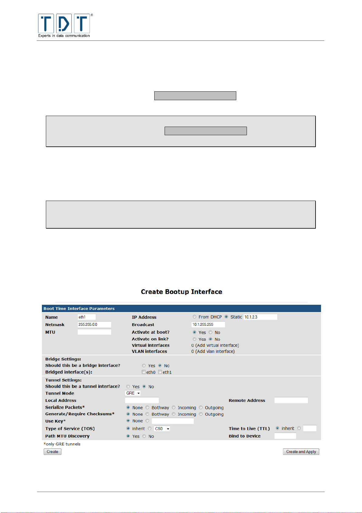
C-M-G Series
Manual
© TDT GmbH
Chapter 5: Network Configuration
Seite 61 von 136
5.10 Network Configuration
Behind module Network Configuration you will find the settings for the network interfaces, routing,
gateway, DNS client and host addresses.
The index page additionally includes an Apply Configuration button, via which the effected
settings can be applied.
Note
Despite saving the settings with the Apply Configuration button, a Permanent
Save is absolutely essential, otherwise the settings will be lost if you reboot the router.
5.10.1 Network Interfaces
Under the menu item Network Interfaces you can configure and add the physical or virtual network
interfaces.
Note
As a result of changes to the network interfaces it might be necessary to log in to
webinterface again using the new IP address.
To create a new permanent interface, click on Add a new Interface in the Interfaces
Activated at Boot Time area. Interfaces created within Interfaces Active Now are temporary
and will be lost after Reboot or »Apply Configuration«.
Enter the values for the interface in the following schedule:
Figure 21: Configuration excaple - Create a new Interface

C-M-G Series
Manual
© TDT GmbH
Chapter 5: Network Configuration
Seite 62 von 136
Command
Description
Name
Designation of the interface e.g.: eth1
IP Address
The IP address that should be applied to the interface
Netmask
The subnet mask for the interface (default: 255.255.255.0)
Broadcast
The broadcast address of the interface. (default: *.*.*.255)
MTU
Maximum Transmission Unit. The maximum permissible length of
a data packet respectively the maximum permissible length of a
data packet data-field when using packet transmitted data
communication. The following standard values are vaild:
X.25 576
Ethernet 1500
ATM (Ethernet) 1500
ATM (Classical IP) 9180
Activate at boot?
Defindes if the interface is enabled at boot time
Activate on link?
Enables the interface only if there is a link detected
Note
This can lead to problems in usage with tunnels (e.g.
IPsec)
Virtual interfaces
Virtual IP addresses for this physical interface can be assigned
here, if the main interface was created. The values correspond to
the ones listed here.
VLAN interfaces
If the physical interface was created, VLAN interfaces can be
assigned to this interface. The values correspond to the ones
listed here.
5.10.1.1 Bridge Settings
Command
Description
Should this be a bridge
interface?
Setup this interface as a bridge
Note
This functionality is used to combine Wi-Fi and
ethernet interfaces to one logical interface
Bridged interface(s):
Select physical interfaces to combine to a bridge interface
5.10.1.2 Tunnel Settings
Command
Description
Should this be a tunnel
interface?
Setup this interface as a tunnel
Tunnel Mode
Set the tunnel mode;
GRE (Generic Routing Encapsulation) or
IP/IP (IP in IP encapsulation)
Local Address
Set the fixed local address for tunneled packets.
Remote Address
Set the remote endpoint of the tunnel.
Serialize Packets*
None
no serialization is used
Bothway
enables sequencing of outgoing packets and
requires that all input packets are serialized

C-M-G Series
Manual
© TDT GmbH
Chapter 5: Network Configuration
Seite 63 von 136
Command
Description
Incoming
requires that all input packets are serialized
Outgoing
enables sequencing of outgoing packets
Command
Description
Generate/Require
Checksums*
None
don‘t use checksums
Bothway
generate/require checksums for tunneled packets in
both directions
Incoming
requires that all incoming packets have the correct
checksum
Outgoing
calculates checksums for outgoing packets
Use Key*
None: no keying will be used
String: use keyed GRE with key (either a number or an IP
address-like dotted quad)
Type of Service (TOS)
Inherit: (Default)
Drop down menu: set a fixed TOS on tunneled packets
Time to Live (TTL)
Inherit: (Default)
Integer: set a fixed TTL on tunneled packets. (range 1-255)
Path MTU Discovery
Enable/disable Path MTU Discovery on this tunnel.
Note
A fixed ttl is incompatible with this option: tunnelling
with a fixed ttl always makes pmtu discovery
Bind to Device
Bind the tunnel to the device NAME so that tunneled packets will
only be routed via this device.
*only GRE tunnels
5.10.2 Routing and Gateways
Using the Routing and Gateways menu you can define which router should be used to reach specific
hosts and networks. Here the units can also be configured as routers between different networks.
Command
Description
Default routes
Interface
Enter the interface for the route (e.g. eth0)
Gateway
Enter the gateway over which the network can be
reached
Act as router?
Yes
The unit operates as a router according to the
following list
No
The routing functionality is deactivated
Static routes
Interface
Enter the interface for the route (e.g. eth0)
Network
Enter the network that should be reached (e.g.
192.168.5.0)
Netmask
Enter the subnet mask of the network to be
reached (e.g. 255.255.255.0)

C-M-G Series
Manual
© TDT GmbH
Chapter 5: Network Configuration
Seite 64 von 136
Command
Description
Gateway
Enter the gateway over which the network can be
reached
Local routes
Interface
Enter the interface for the route (e.g. eth0)
Network
Enter the network that should be reached (e.g.
192.168.5.0)
Netmask
Enter the subnet mask of the network to be
reached (e.g. 255.255.255.0)
Type
host
route to a host
unreachable
Set route to unreachable; an ICMP
unreachable will be generated and
returned to the source address.
Note
The current settings must be stored before entering more static or local routes using the
Add or Submit button.
5.10.3 DNS Client
The router resolver settings are configured using the DNS client menu, it defines the resolution of the
host.
Command
Description
Hostname
Hostname des Routers
DNS servers
The DNS server, which is interrogated by the router when an
unknown host name is used
Resolution order
Name resolution order
Host:
The router attempts to resolve the names itself
DNS:
The router attempts to resolve the names via the server
defined in the DNS list
NIS:
The router attempts to resolve the names via Network
Information Services
NIS+:
The router attempts to resolve the names via Network
Information Services Plus
Search domains
The search domains list contains a list of local host names which,
following the abortive processing of the name resolution, resolves
the local names (e.g. M3000.local)
5.10.4 Host Addresses
Using the Host and Address(es) menu the host names stored under /etc/hosts can be displayed and
modified. To insert a new host address click on the button Add a new host address .
Command
Description
IP Adress
Enter the IP address of the host here

C-M-G Series
Manual
© TDT GmbH
Chapter 5: Network Configuration
Seite 65 von 136
Command
Description
Hostname
Enter the new host name here
5.11 OpenVPN
OpenVPN makes it possible to establish VPN connections over encrypted TLS connections. For
encryption, OpenVPN uses the OpenSSL library. OpenVPN uses UDP or TCP to transport data.
Note
First of all you have to create a new OpenVPN server.
5.11.1 Add new server/client
Command
Description
Peer name
Name of the connection
Port to use
Port for the OpenVPN connection
Operating Mode
Routed VPN: all usually used network protocols based on IP are
transported (Layer 3). A connection to the network „behind“ the
OpenVPN-peer is not possible (Point-to-Point connection)
Bridged VPN (plain tunneling): Layer 2 of the Ethernet frame
will be fully tunneled (e.g.: IPX protocol). Client may get an IP
address assigned from a DHCP server behind the VPN server.
Create appropriate DiffieHellman Random File
String = Length of the Diffie-Hellman Key
The higher the String the longer it takes time to create
the random file.
5.11.2 Edit existing peer
Command
Description
Peer name
Name of the connection
Operating Mode
Defines the operation mode
Port to use
Port for the OpenVPN connection
Protocol
Uses the selected protocol
Standard: UDP
TCP connection retry
Enable internal datagram fragmentation, so that no UDP
datagrams are sent, which are larger than the here defined value.
Internatl UDP fragmentation
Limits the size of the sent packets
TCP send size to fit UDP
Clients may be assigned IP addresses from the defined IP range.
The OpenVPN servers uses always .1 from the IP rage (e.g.
192.168.0.0/24)
Network to assign client
addresses
Clients may be assigned a netmask from the defined range
Netmask to assign client
addresses
All packets are encrypted with the selected algorithm

C-M-G Series
Manual
© TDT GmbH
Chapter 5: Network Configuration
Seite 66 von 136
Command
Description
Encrypt packets with cipher
algorithm
Name of the connection
Listen on IP
All: accepts connections on all network addresses
String: accepts connections only on given network addresses
Authenticate packets with
HMAC
The authentication of packets the packets occours with the given
HASH algorithm
Keepalive
Ping: ping remote over the TCP/UDP control channel if no
packets have been sent for at least n seconds.
Ping-Restart: restarts connection after n seconds pass without
reception of a ping or other packet from remote. (SIGUSR1
Signal)
(Default: 120; Disable: 0)
Max. new connections
Limit server to a maximum of n clients to connect in m seconds
(Servers only)
Allow clients with same
common name
Yes: clients are allowed to use the same name
No: clients have to use different names; if a client connects with
an existing name, the „older“ clients connection will be rejected.
(Servers only)
Route client-to-client traffic
Yes: clients are allowed to exchange data to each other
No: clients are not allowed to exchange data to each other
(Servers only)
Limit concurrent clients
Max. number of simultanously active connections to the
OpenVPN server (Servers only)
Allow remote to change IP
and/or port
Allows the client to use an own IP address and an own port
respectively to change servers preset
Enable Management
Yes: starts an TCP server on the given port for management. For
security reasons it is recommended to set the IP address to
127.0.0.1 (localhost)
(Servers only)
Client’s remote host(s)
Defines the peers (Clients only)
Priority: priority of the server
IP address: servers IP address
Port: OpenVPN Server port
Accept only host with X509
or common name
Accept only host with X.509 or common name (Clients only)
TLS Cipher Algorithm
Packets are encrypted with the given algorithm
TLS Retransmit Timeout
(sec)
If a control packet is sent to the OpenVPN client, it has to be
answered by the client within n seconds
(Default: 2)
Renegotiate Data Channel
Key (sec)
The data channel key is anew negotiated every n seconds
Use PKCS12 File
Uses a PKCS12 certificate
Certification Authority
Defines the Certification Authority (CA)
Certificate
.pem Certificate
Key
The clients private certificate
Diffie-Hellman Random File
File in .pem format, which contains the Diffie-Hellman parameter
Certificate Revocation File
Defines the Certificate Revocation File to verify the clients
certificate

C-M-G Series
Manual
© TDT GmbH
Chapter 5: Network Configuration
Seite 67 von 136
Command
Description
Enable username/password
authentication
Enable/disable username/password authentication
Authentication script
Path to authentication script (Servers only)
Require certificate
authentication additionally
Additional certificate authentication is (not) required
(Servers only)
Username
Username for the OpenVPN connection (Clients only)
Password
Password for the OpenVPN connection (Clients only)
Authentication file
Path to authentication file (Clients only)
‘chroot’ to dir after
initialization
No: (default)
String: Defines the given directory as the new top level directory
(/)
Change user after
initialization
No: (default)
Auswahl: Changes the User-ID from OpenVPN to the defined
string
Change group after
initialization
No: (default)
Auswahl: Changes the Group-ID from OpenVPN to the defined
string
Retain key files (persist-key)
No: (default)
Yes: already read in key-files are retained and aren’t read in once
more
Retain TUN/TAP devices
(persist-tun)
Yes: established connections will not be rejected and start/stop
scripts will not be executed
No: (default)
Additional configurations
OpenVPN supports more than the listed parameters. If you need
one of the parameters, you are able to define them here.
Script to execute after VPN
is up
The defined script will be executed after the OpenVPN connection
is established. The script is running under the user rights given in
„Change user after initialization“.
Script to execute after VPN
is down
The defined script will be executed after the OpenVPN connection
is stopped. The script is running under the user rights given in
„Change user after initialization“.
Logging
Off: the log function is deactivated
Truncate logfile at startup: overrides an existing log file; if file
does not exist, it will be created
Append to logfile: the log will be added to an existing file; if file
does not exist, it will be created
Logfile
Status announcements of OpenVPN are stored in the given log
file
Log same consecutive
messages
A maximum of n messages of the same message type will be
saved
Output Verbosity
Defines the details of issue of OpenVPN.
0: no issue
1 - 4: normal use
5: Read & Write for each packet
6 - 11: Debug info range
Write operational status to
file
No: OpenVPN status will not be written to a file
Yes: stores OpenVPN status in the file
Write status interval
All n seconds a status will be stored

C-M-G Series
Manual
© TDT GmbH
Chapter 5: Network Configuration
Seite 68 von 136
Command
Description
Status file
Name of the status file
5.12 PPP
The PPP Functions menue is used to manage settings all around the point-to-point protocol (PPP).
In order to establish a configured PPP connection the Connection Management (Chapter: 5.3) is used.
Note
For routers which are equipped with a LTE modem (Cxxxxl), a connection establishment
using the WWAN module is required. (Networking > WWAN)
For routers which are equipped with a HSPA modem (Cxxxxh), a connection establishment
using the WWAN module is recomended. (Networking > WWAN)
5.12.1 PPP Interfaces
In this menu ppp connections can be created, administrated and displayed. Following informations are
listed in the overview:
Command
Description
Name
Name of the PPP connection
Type
Connection type of the PPP connection. Possible types: ADSL,
ISDN, ISDN Dial In, UMTS/GPRS
Phone Number(s)
ISDN phone numbers for outgoing ISDN connections
APN
Access Point Name with UMTS/GPRS connection
Username
Username of the connection
Local IP
Local IP address
Remote IP
IP address of the remote station
Using Add a new PPP interface link will create a new connection.
First specify name and type for the new ppp connection and click the Create button. After that the
configuration sheet will be opend.
5.12.1.1 Basic PPP configuration for interface ppp#
According to the chosen connection type specific settings are necessary, listet in the following chapters.
5.12.1.1.1 ISDN PPP Interface Parameter
Command
Description
Phone number(s)*
The value defines the ISDN phone number(s), which will be dialed
during connection establishment.
Numberprefix
The value defines the prefix that will be added to every phone
number.

C-M-G Series
Manual
© TDT GmbH
Chapter 5: Network Configuration
Seite 69 von 136
Command
Description
Outgoing MSN
The value defines the outgoing phone number, which will be
passed to the remote station.
Username
The user name assigned by your provider
Password
The password for the account
Verify Password
Re-enter the password to verify
Ask for DNS server
addresses
The remote station is interrogated about known DNS servers,
which will entered as DNS servers
Maximum Transmit Unit
The value defines the maximum size of a transmitted data packet
Maximum Receive Unit
The value defines the maximum size of a received data packet
Protocol
This parameter defines the connection protocol. It must
correspond to the value in the remote station
5.12.1.1.2 ISDN Dial-In PPP Interface Parameter
Command
Description
Incoming MSN(s)*
Specifies the MSN(s) that are monitored for incoming ISDN calls.
If no MSN is set, all incoming calls are accepted. (comma
seperated)
Accept Calls From*
The definded Peers/Callers are allowed to establish a connection:
Corresponding numbers are given here, separated by commas.
To accept all incoming calls, leave this field empty.
Maximum Transmit Unit
The value defines the maximum size of a transmitted data packet
Maximum Receive Unit
The value defines the maximum size of a received data packet
Protocol
This parameter defines the connection protocol. It must
correspond to the value in the remote station
5.12.1.1.3 PPPoE Interface Parameter
Command
Description
Use Interface
The interface for Internet access can be selected here
Username
The user name assigned by your provider
Password
The password for the account
Verify Password
Re-enter the password to verify
Ask for DNS server
addresses
The remote station is interrogated about known DNS servers,
which will entered as DNS servers
Maximum Transmit Unit
The value defines the maximum size of a transmitted data packet
(Default: 1492)
Maximum Receive Unit
The value defines the maximum size of a received data packet
(Default: 1492)
PPPoE Access Concentrator
Name
PPPoE Access Concentrator Name (optional)
PPPoE Service Name
PPPoE Service Name (optional)

C-M-G Series
Manual
© TDT GmbH
Chapter 5: Network Configuration
Seite 70 von 136
5.12.1.1.4 UMTS/GPRS PPP Interface Parameter
Note
For routers which are equipped with a LTE modem (Cxxxl), the connection establishment
recommends using the Networking > WWAN.
Command
Description
Use Device
The device for this connection can be selected here
Connection Type
Only GPRS
only a GPRS connection will be established
Only UMTS
only a UMTS connection will be established
Auto
select connection type according to availability
SIM card
Specifie the SIM-slot for this connection
PIN (for SIM card)
If a PIN is set on sim card, enter it here
APN
The Access Point Name of the mobile telephone system provider
Username
The user name assigned by your provider
Password
The password for the account
Verify Password
Re-enter the password to verify
Ask for DNS server
addresses
The remote station is interrogated about known DNS servers,
which will entered as DNS servers
Maximum Transmit Unit
The value defines the maximum size of a transmitted data packet
Maximum Receive Unit
The value defines the maximum size of a received data packet
5.12.1.2 Advanced PPP configuration for interface ppp#
For a simple connection, the Advanced PPP parameters are not required, special applications may
require a more in-depth configuration.
The possible Advanced PPP parameters for each connection type are described below.
Because most of the advanced parameters would repeat, overlapping preferences will be listed below the
connection type specific settings.
5.12.1.2.1 ISDN PPP Interface Parameter
Command
Description
Wait for Callback
Activates/deactivates wait for callback
Time to Wait For Callback
Wait n seconds for callback (Default: 60 sec)
Trys before giving up
In case of error a maximum of n re-tries will be initiated
(Default: 4)
Timeout before giving up
Connection establishment will be attempted for n seconds
(Default: 60 sec)

C-M-G Series
Manual
© TDT GmbH
Chapter 5: Network Configuration
Seite 71 von 136
Command
Description
PPP multilink protocol
Multilink PPP provides a bundeling of two ISDN B channels to one
logical connection (MLPPP)
No
don’t combine ISDN B channels to a bundle
Yes
combine ISDN B channels to a bundle
Auto
use bundle if possible
Short sequence numbers in
ML-PPP
Enables the use of short (12-bit) sequence numbers in multilink
ppp headers, instead of the default 24-bit sequence numbers.
5.12.1.2.2 ISDN Dial-In PPP Interface Parameter
Command
Description
Do Callback
Perform callback
Callback Number(s)*
Specifies the ISDN MSN(s) which will be dialed for callback.
(comma seperated)
Time to Wait Befor Callback
Wait n seconds befor performing a callback (Default: 60 sec)
Trys before giving up
In case of error a maximum of n re-tries will be initiated
(Default: 4)
Timeout before giving up
Connection establishment will be attempted for n seconds
(Default: 60 sec)
PPP multilink protocol
Multilink PPP provides a bundeling of two ISDN B channels to one
logical connection (MLPPP)
No
don’t combine ISDN B channels to a bundle
Yes
combine ISDN B channels to a bundle
Auto
use bundle if possible
Short sequence numbers in
ML-PPP
Enables the use of short (12-bit) sequence numbers in multilink
ppp headers, instead of the default 24-bit sequence numbers.
5.12.1.2.3 PPPoE Interface Parameter
Command
Description
PPPoE Access Concentrator
Name
PPPoE Access Concentrator Name (optional)
PPPoE Service Name
PPPoE Service Name (optional)

C-M-G Series
Manual
© TDT GmbH
Chapter 5: Network Configuration
Seite 72 von 136
5.12.1.2.4 UMTS/GPRS PPP Interface Parameter
Command
Description
Numeric Provider ID
Set a prefered mobile operator for the radio connection using the
»Mobile Network Code« of your prefered mobile operator.
This might be useful or necessary, if several providers are
available, to suppress a fluttering between two or more providers.
The Numeric Provider ID is a combination of the three-digit Mobile
Country Code (MCC) and the two-digit Mobile Network Code
(MNC) and is specified without separators or spaces. (see 14.2
Important Informationen)
5.12.1.2.5 General PPP settings
Command
Description
On Demand Calling
Specifies whether the connection will only be established when
data has been sent (yes), or it will be established automatically
during start up. (Default: No)
Idle time before disconnect
The connection will be disconnected after n seconds, when no
more data has been sent or received
LCP-Echo-Failure
Using this option, the PPP connection will be closed if ther is no
reply to n LCP echo requests.
This option can be used to automatically disconnect a connection
if there is no response to the peer or which is already physically
disconnected.
LCP-Echo-Interval
This option causes an LCP echo request to be sent every n
seconds.
This option would be used in conjunction with the LCP-Echo-
Failure option.
Clamp MSS
This function sets the Maximum Segment Size (MSS). It is
necessary to connect networks with different MTU’s, and thereby
to avoid transmission errors due to a possible fragmentation.
For this, the MSS is either automatically determined based on the
»Path MTU« (PMTU, the smallest MTU for the active network
path), or reduced to a predefined value.
Passive Mode
With the LCP option »passive mode« the router tries to establish
a PPP connection. If the remote station does not answer, it will
passively wait until the remote station creates a valid LCP
connection instead of a connection disconnect. (Default: No)
Silent Mode
Using the Silent Mode option, no LCP packets will be transmittet
for a connection establishment, until a valid LCP packet is
received from the remote station. (Default: No)
Magic Number negotiation
Activates the transmission of the magic number, a randomly
generated number that is used in LCP to identify the PPP
connections end points. With this option a possible loop-back can
be recognized. (Default: Yes)

C-M-G Series
Manual
© TDT GmbH
Chapter 5: Network Configuration
Seite 73 von 136
5.12.1.2.6 Logging Parameters
Command
Description
Connection Debugging
Activates the connection debugging, to simplify the
troubleshooting. All received and transmitted control packets will
be logged to /var/log/messages. (Default: No)
Additional Logfile
Inserts log messages from this PPP Connection to a additional
logfile. (e.g. /var/log/ppp/umts/ppp0.log) (Default: No)
Show PAP password in log
In default during PAP packet monitoring the password will not be
entered to the log file. If the password output is required, it can be
activated here. (Default: No)
5.12.1.2.7 Networking Parameters
Command
Description
PPP IP addresses
From peer
The IP address will be assigned by the
remote station (Default)
Local IP
Fixed IP addresses for router and peer
allocated by the provider
Accept local IP address
The remote station is allowed to assign the router’s local IP
address (Default: No)
Accept remote IP address
Allowes the remote station to assign the router’s remote IP
address (Default: No)
PPP interface netmask
Based on Remote IP
the netmask is defined using the remote
IP address (Default)
String
Defines the netmask for this PPP
interface
Force Local IP
No
(Default: No)
Yes, set to
Forces the specified local IP
5.12.1.2.8 Authentication Parameters
Command
Description
Require authentication
No, but prevent
routed IPs
only allow IP adresses where currently no
route is present (Default)
Never
the peer don’t need to authenticate itself
Always
the peer always requires to authenticate
itself
Refuse PAP
Authentication requests via PAP (Password Authentication
Protocol) will be rejected (Default: No)
Require PAP
The peer is required to authenticate itself using PAP. (Default: No)
Refuse CHAP
Authentication requests via CHAP (Challenge Handshake
Authentication Protocol) will be rejected. (Default: No)
Require CHAP
The peer is required to authenticate itself using CHAP. (Default:
No)
Max. CHAP challenge
transmissions
The CHAP authentication will attempt n times (Default: 10)

C-M-G Series
Manual
© TDT GmbH
Chapter 5: Network Configuration
Seite 74 von 136
Command
Description
CHAP restart interval
Set the CHAP restart timeout between the CHAP challenge
transmissions to n seconds (Default: 3 sec)
Refuse MS-CHAP
Reject MS-CHAP authentication requests (Default: Yes)
Refuse MS-CHAPv2
MS-CHAPv2 authentication requests will be rejected
(Default: Yes)
Refuse EAP
Authentication requests via EAP (Extensible Authentication
Protocol) will be rejected (Default: No)
Append domain name
Inserts the entered domain name to the local host name for
authentication purposes.
(e.g.: Local host name is router1 and domain name is
firma.com uses router1.firma.com as »fully qualified
domain name« during authentication.
5.12.1.2.9 Compression Parameters
Command
Description
VJ-Compression
Activates Van Jacobson TCP/IP header-compression in both
directions. (Default: Yes)
VJ-Connection-ID
Compression
Activates connection ID-compression within Van Jacobson
Compression, so the connection ID byte will be compressed.
(Default: Yes)
Protocol Field Compression
Set transmission of »protocol field compression« in transmit and
receive direction. (Default: Yes)
Address/Control
Compression
Activates/deactivates »address/control compression« in both
directions (transmit and receive) (Default: Yes)
Predictor-1 Compression
Using Yes »Predictor-1 Compression« is required, set to No to
refuse »Predictor-1 Compression« (Default: Auto)
BSD Compression
Activates BSD compression scheme, requests the peer to send
packets compressed with a maximum code size of nr bits.
Outgoing packets will be sent with a maximum compression of nt
bits.
A value 0 disables compression in the corresponding direction.
No will refuse compression, Auto assumes the peer settings.
(Default: Auto)
Deflate Compression
Activates Deflate compression scheme, requests the peer to send
packets compressed with a maximum window size of 2**nr bits.
Outgoing packets will be sent with a maximum window size of
2**nt bits.
A value 0 disables compression in the corresponding direction.
No will refuse compression, Auto assumes the peer settings.
(Default: Auto)
Compression Control
Protocol negotiation
No deactivates the compression control protocol for transmission.
This option should only be used if remote station does not accept
CCP transmission. (Default: Yes)

C-M-G Series
Manual
© TDT GmbH
Chapter 5: Network Configuration
Seite 75 von 136
5.12.1.3 Parameters for interface pppX when used in Static Connections
Important!
Don´t use the following parameters in combination with the Connection Manager.
This options only works using ISDN connections.
Command
Description
Add a defaultroute
After a ppp connection is established successfully, a defaultroute
via this interface will be set.
PPP interface routing metric
Specify the routing metric for this interface.
Update DNS Server directly
Perform a DNS Server Update once the interface comes into
service.
Update DynDNS entry
Perform a Dynamic DNS Update once the interface comes into
service.
5.12.2 PPP Accounts
In the PPP Acounts menu PAP (Password Authentication Protocol) or CHAP (Challenge Handshake
Authentication Protocol) users can be created and administered.
5.12.2.1 Create new PPP CHAP/PAP account
Kommando
Beschreibung
Username
Any
The username can be empty or consist of
any ASCII characters.
String
The defined username must be used.
Password
None
There will not be any password control in
login.
From File
The password will be compared with
those stored in the password file.
Set To
The password will be set to a defined
value. Please observe lower and upper
case letters.
Server
Any
There is no control of the incoming server
String
The login can only be made on the
defined server.
Valid Addresses
Allow any
No address control will be carried out
during login.
Allow none
The account is blocked.
Allow listed
Only defined addresses are allowed to log
on.

C-M-G Series
Manual
© TDT GmbH
Chapter 5: Network Configuration
Seite 76 von 136
5.13 Postfix Configuration (M3000, G5000 only)
Postfix is an open source Mail Transfer Agent. This service is only included in M- and G-Series devices.
Please load the description from the official Postfix website under http://www.postfix.org
5.14 QoS Control
Using Quality of Service (QoS) it is possible, to regulate the available bandwith of a connection and for
example to distribute it across different ports or IPs.
During a normal internet connection via modem each packet is stored sequentially in the so-called packet
queue. The size of the packet queue exceeds the bandwith of the internet connection. All stored packets
are processed sequentially. Likewise, QoS only administers a packet queue within a router. Thereby you
have the possibility, using the QoS rules, to decide which packets have priority and which ones must wait.
If these rules are correctly configured, the router sends the packets from its packetqueue to the modem at
such a speed, that they don’t have to wait in line of the modem’s packetqueue. In this case, it is as if the
queue has been fetched from the modem to the router.
5.14.1 Outgoing Interfaces
5.14.1.1 Interface parameters
Command
Description
Interface
Selects the incoming interfaces
Enable Interface
Interface will be activated/deactivated
5.14.1.2 Root Qdisc Parameters
Note
All QoS rules will be carried out as user root.
5.14.1.2.1 TBF (Token Bucket Filter)
Because of this functionality, there are three scenarios:
If the network packets for retransmission arrive at the same rate as the TBF can create new
tokens, the Qdisc can immediately transmit them.
If the network packets arrive at a faster rate, then they must wait until enough tokens are
available. This reduces the transmission rate to the token rate.
If the packets arrive at the TBF with a lower rate or no packets arrive at all, the surplus tokens
trickle back into the bucket. If it is at any time full, all following tokens flow into an electronic gully.
When packets come again with a high rate, they use the collected tokens. This means that the
Qdisc is permitted to send a higher rate as the TBF is really allowed. This excess rate is called
burst.
Command
Description
Rate (kbit/s)
Gives the maximum delay, which the packets are delayed
(resident in the queue)

C-M-G Series
Manual
© TDT GmbH
Chapter 5: Network Configuration
Seite 77 von 136
Command
Description
Burst (Bytes)
Defines the size of the bucket and hence limits the amount of data
in a burst
Latency (ms)
Defines the maximum time in ms, which a packet is allowed to be
in the queue
Peakrate (kbit/s)
Defines the maximum bandwith, which is available during the
burst. The maximum peak rate results from the average packet
size multiplied by the timer rate.
Mpu (Bytes)
The ‘Minimum Packet Unit’ defines the minimum token usage for
a packet.
Minburst (Bytes)
Defines the outgoing bucket size
5.14.1.2.2 SFQ (Stochastic Fairness Queueing)
With a line running at full capacity, the SFQ (Stochastic Fairness Queueing) takes care of fairness within
the active connections. For this, 127 FIFO queues are introduced, which transmit alternatively. A hash
procedure decides, which connections are assigned to which queues. However, occasionally a number of
connections must share the same queue, whereas others use a queue exclusively.
Command
Description
Perturb
Defines the time-span for a hash function change
Quantum
Defines the number of bytes that a queue can send at one time.
This value must be at least as large as the current packet size
(MTU). Otherwise the larger packets will be stuck in the queue.
5.14.1.2.3 BFIFO (Bytes First In First Out)
Command
Description
Limit
Number of bytes that the queue can accommodate.
5.14.1.2.4 PFIFO Packet First In First Out
Command
Description
Limit
Number of packets that the queue can accommodate.
5.14.1.2.5 DSMARK
DSMARK doesn’t control, monitor or change the data traffic. It also doesn’t prioritise, delay or rejects
packets. It solely marks packets with the help of the DS field in the packets.
Command
Description
Number of Indizes
The classes are numbered. n is a parameter, which defines the
size of an internal table, that defines the hierarchy of transit
through the queue.

C-M-G Series
Manual
© TDT GmbH
Chapter 5: Network Configuration
Seite 78 von 136
Command
Description
Default Index (optional)
Packets that do not correspond to any defined rules are
processed in the default class. This value defines the default
class.
Set TC-Index
Yes: This queue rule copies the ToS – value (Type of Service) of
the packets (DS-value)
5.14.1.2.6 HTB (Hierarchical Token Bucket)
Command
Description
R2Q
The R2Q defines a class, which contains all unclassified packets
5.14.1.2.7 PRIO (Filter)
Command
Description
Number of Bands
Defines a class. The higher the number, the higher the value of
the class
5.14.1.2.8 PRIO (Priomap)
Command
Description
Number of Bands
Defines a class. The higher the number, the higher the value of
the class
5.14.2 Incoming Interfaces
There are also possibilities to control the incoming network traffic with rules. This implementation
basically differs from the others, because the incoming packets do not bottle up at the interface. As a
result a rule for incoming traffic can only be used together with filters and policies.
5.14.2.1 Interface parameters
Command
Description
Interface
Selects the incoming interfaces
Enable Interface
Interface will be activated/deactivated
Attached Interface
Defines on which inteface(s) the new QoS rules should be
activated
The Root Qdisc parameters are equal to chapter 5.14.1.2.
5.14.3 Interface Statistics
Statistics for incomming and outgoing QoS interfaces are listed here.

C-M-G Series
Manual
© TDT GmbH
Chapter 5: Network Configuration
Seite 79 von 136
5.15 SNMP
The Simple Network Management Protocol (SNMP) is part of the internet protocol family. It was
developed to control and monitor network elements (Router, Server, Switches, etc) from a central
management station.
SNMP defines a community based administration framework, using it to administer the different SNMP
elements. Each SNMP community is a group of units, which includes at least an agent and a
management system. The characteristics of managed network components which can be accessed and
modified via an agent, the so-called „managed-objects”, will be defined in the Management Information
Base (MIB).
5.15.1 Access Control
The SNMP protocol does not include access or password control mechanisms. In the SNMP access
control you can regulate the access and authorisation which are available via SNMP.
Command
Description
Community Name
Name of the SNMP community to which the router should belong.
Each SNMP community should have at least one SNMP agent
and belong to a managed system. It does make sense, that a
community consolidates different working groups (e.g. Internet,
printer, sales, marketing, etc). Individual SNMP agents can also
be represented in different communities (e.g. routers)
Source:
Default: All SNMP requests will be answered
Hostname: SNMP requests from the defined host will be
accepted
Subnet: SNMP requests from the following networks (IP
address/Subnet e.g. 10.1.4.0/24) will be accepted.
Restricted OID:
None: Access to the total MIB permitted
OID: The value OID controls the accesslevel of the MIB
(Management Information Base) tree; it will only grant access
underneath the entered value. The MIB contains the definition of
all properties, which can be selected or modified via SNMP.
Access Mode:
Read Only: Within the MIB, only read access is permitted. When
using this, the SNMP can therefore only interrogate the respective
status and properties, but not make any changes.
Read/Write: Within the MIB, read and write access is permitted.
When using this, the SNMP can therefore interrogate the
respective status and properties and make changes
Process:
Activates/deactivates this community
5.15.2 Sysinfo Setup
The RFC1214-MIB definition includes various manageable objects and function groups. To clearly
organise these objects and function groups, you can use the SNMP Sysinfo Setup to define the value
sysLocation and SysContact for the router.
Command
Description
System Location
Informative information about the physical location

C-M-G Series
Manual
© TDT GmbH
Chapter 5: Network Configuration
Seite 80 von 136
Command
Description
System Contact
Informative information about the system e.g. the name of the
person, the group or the organisation that is responsible for the
service, maintenance, etc. of the node
5.15.3 Trap Control
Traps are unrequested messages that, are sent from an agent to a management system as soon as
something unforeseen or interesting for the management system happens.
5.15.3.1 SNMP Create New Trap Control
Command
Description
Symbolic Name
Description of the trap control
Destination
Hostname: Accured trap will be sent to the following host
IP: Accured trap will be sent to the following IP address
Community
Name of the trap community
Type
SNMPv1 Trap Receiver: SNMP Server receives SNMP Version 1
traps
SNMPv2 Trap Receiver: SNMP Server receives SNMP Version 2
traps
SNMPv2 Inform Receiver: SNMP Server receives SNMP
Version 2 inform traps
Process
Yes: Activates/deactivates this trap control
5.15.4 (Sub)Agent Configurations
Use this menu to configure the SNMP-Monitoring.
5.15.4.1 Common Settings
Command
Description
Send trap on authentication
failures:
Yes: The router sends a trap when an invalid authentication has
taken place
No: The router does not send a trap when an invalid
authentication has taken place
Enable System Monitoring:
Yes: Activates the sub-agent monitoring
No: Deactivates the sub-agent monitoring
5.15.4.2 Monitor Running Processes
5.15.4.2.1 SNMP Agent Create Process Monitor
Command
Description
Process:
Name of the process be monitored
Max. running instances:
Maximum number of permitted instances. If no value or the value
‘0‘ is entered, then the permitted instances are endless.

C-M-G Series
Manual
© TDT GmbH
Chapter 5: Network Configuration
Seite 81 von 136
Command
Description
Min. running instances:
Minimum number of necessary instances. If no value is entered
and the value max. is not defined, then a value of ‘1’ will be
assumed.
Process:
Monitor for this process will be activated/deactivated
5.15.4.3 Monitor Disk Space
Command
Description
Disk mount path 1:
Path of the free memory to be monitored in device 1
Minimum limit
When this value is undershot, a trap will be sent
Bytes: Minimum free memory in bytes
Percentage: Minimum free memory in percent
Disk mount path 2:
Path of the free memory to be monitored in device 2
Minimum limit
When this value is undershot, a trap will be sent
Bytes: Minimum free memory in bytes
Percentage: Minimum free memory in percent
Disk mount path 3:
Path of the free memory to be monitored in device 3
Minimum limit
When this value is undershot, a trap will be sent
Bytes: Minimum free memory in bytes
Percentage: Minimum free memory in percent
5.15.4.4 Monitor File Sizes
Command
Description
Destination
Path details of the files to be monitored
(e.g.: /var/log/messages)
Max. Size in Byte
Maximum size of the files in bytes
Process:
Yes: The file will be monitored
No: The file will not be monitored
Note
The maximum number of files to monitor is 20!
5.15.4.5 Monitor Load Averag
Command
Description
Maximum load for 1 minute
average:
Maximum permissible average of the CPU utilisation within the
last minute. When this value is exceeded, a trap will be sent.
Maximum load for 5 minute
average:
Maximum permissible average of the CPU utilisation within the
last five minutes. When this value is exceeded, a trap will be sent.
Maximum load for 15 minute
average:
Maximum permissible average of the CPU utilisation within the
last fifteen minutes. When this value is exceeded, a trap will be
sent.

C-M-G Series
Manual
© TDT GmbH
Chapter 5: Network Configuration
Seite 82 von 136
5.16 SSH Server
SSH is a protocol enabling users to call a router, similar a Telnet. However, all SSH connections are
encypted and certified thereby avoiding passwords or transmitted data being seen by hackers.
5.16.1 Authentication
All settings related to SSH securty and also login information beeing displayed can be configured here.
Command
Description
Allow authentication by
password?
Yes (Default): User can logon to a router using a password
No: User can only logon with a public key
Allow login by root?
Yes (Default): User can logon under root
No: User cannot logon under root
Only with RSA auth: User can logon under root when an RSA
authentication has been carried out
Only for commands: User can logon under root to enter
commands
Check permissions on key
files?
Yes (Default): A user’s authorisation will be assigned dependant
on the deposited keys
No: A user’s authorisation will be assigned dependant on the user
name
Ignore users' known_hosts
files?
Yes: The SSH daemon ignores the $HOME/.ssh/known_hosts
files during an RSA authentication
No: THE SSH processes ignores the $HOME/.ssh/known_hosts
file during an RSA authentication
Pre-login message file
None (Default): No message will output before login.
String: The text message will output in the specified file before
login.
User authorized keys file
Default (~/.ssh/authorized_keys): The authentication keys are
located in the default directory
String: The authentication keys are located in the declared
directory
Permit logins with empty
passwords?
Yes: Login with an empty password is permissible
No (Default): Login will require a password
Allow RSA authentication?
Yes (Default): Login with RSA authentication is permissible
No: Login with RSA authentication is not permissible
Display /etc/motd at login?
Yes (Default): The text message stored unter /etc/motd will be
output after login
No: No message will be output
Allow login just by
hosts.equiv
and .rhosts?
Yes: The files hosts.equiv and .rhosts will be used for
authentication (security risk)
No (Default): The files hosts.equiv and .rhosts will not be used for
authentication
Ignore .rhosts files?
Yes (Default): The .rhosts file will be ignored during dial-up
No: The .rhosts file will not be ignored during dial-up
Check hosts.equiv and
.rhosts
for RSA authentication?
Yes (Default): The files hosts.equiv and .rhosts will be used for
RSA authentication
No: The files hosts.equiv and .rhosts will not be used for RSA
authentication

C-M-G Series
Manual
© TDT GmbH
Chapter 5: Network Configuration
Seite 83 von 136
5.16.2 Networking
SSH server includes configuration options to setup the monitored IP addresses, to define the ports to use
and several protocol settings. To configure these options use the Networking menu.
Command
Description
Listen on addresses
All addresses (Default): All IP addresses of the router will be
monitored on an incoming SSH connection
Entered below…: Only the following IP addresses of the router
will be monitored on an incoming SSH connection
Listen on port
Default (22): The port 22 of the router will be monitored on an
incoming SSH connection
String: The declared router port will be monitored on an incoming
SSH connection
Disconnect if client has
crashed?
Yes (Default): The router terminates the connection automatically
when the client has been disconnected
No: The router doesn’t terminate the connection when the client
has been disconnected
Allow TCP forwarding?
Yes (Default): Users can tunnel the client’s TCP connections in
the router network
No: Users cannot tunnel the client’s TCP connections in the
network
Reverse-validate client IP
addresses?
Yes (Default): The router compares the host names with the IP
addresses of the DNS server
No: The router accepts the IP addresses without querying the
DNS server
5.16.3 Access Control
In default, every configured user can get remote access to the router. At this point user and groups for
SSH access can be defined.
5.16.4 Miscellaneous Options
This menu includes options that do not fit in other categories.
Note
X11 is not implemented!
Command
Description
Allow X11 connection
forwarding?
Yes: permittes X11 forwarding for Unix/Linux users
No: disabling X11 forwarding
X11 display offset
Default: 10
String: Specifies the first display number available for X11
forwarding
Full path to xauth program
Default: /usr/X11R6/bin/xauth
String: specified path to xauth

C-M-G Series
Manual
© TDT GmbH
Chapter 5: Network Configuration
Seite 84 von 136
Command
Description
System log facility
The syslog service is used to log failures and information displays
from SSH users. These can be used in connection with the
system protocol module. When using the default parameter, all
services will be logged.
Default: services will be logged
String: Only the selected services will be logged
Logging level
Default: The logging level is set to Info
String: The logging level is set to a specified value, whereby
Quiet represents the lowest and Debug the highest level
Server key size
Default: The authentication key has 128 Bit
String: The authentication key has the given number of bits
Server key regeneration
interval
Default: The SSH key will never be updated
String: The SSH key will be repeatedly actualised after a
specified value in seconds
PID file
Default: The sshd.pid file is stored under /var/run/sshd.pid
String: The sshd.pid file is stored in the specified directory
Use separate unprivileged
process?
Yes: The SSH daemon starts different processes
No: The SSH daemon only runs on one process
5.16.5 Client Host Options
Specifie rules for individual hosts in this menu.
Command
Description
Login as user
Normally if no username is given on the ssh command line, the
name of the current user is used to login to the remote SSH
server. However, this option can be used to specify a different
default username for a particular host or hosts.
Escape character
When making an interactive SSH login, the escape character can
be used to break out of the connection and close or suspend it.
Compress SSH traffic?
If this option is enabled, the SSH client will compress all data sent
to this host with the gzip algorithm. This can be useful if you are
copying large files with scp over a slow link.
Local ports to forward to
server
In this table you can enter local port numbers which will be
forwarded to some host and port by the SSH server. This can be
useful if your only access to some network is via SSH login to one
machine on that network, and you want to access other services
like web or POP servers.
Server ports to forward to
local
In this table you can enter port numbers on the server which will
be forwarded to some host and port on the client machine's
network.
5.16.6 User SSH Key Setup
In this menu you can define SSH options for new local users of a router.
Command
Description
Setup SSH key for new Unix
users.
When this option is activated, all newly registered local users
must first generate an SSH key

C-M-G Series
Manual
© TDT GmbH
Chapter 5: Network Configuration
Seite 85 von 136
Command
Description
Copy new identify.pub to authorized_keys
The SSH key will be stored in the home directory of the user
under .ssh/authorized_keys
Use password as key
passphrase.
The user password will be used as key
5.17 SSL Tunnels
This menue provides the ability to configure the Stunnel service and add new stunnel connections.
Stunnel works as a universal SSL encrypted tunnel between client and router. Thereby it is possible to
encrypt any TCP connection in a very easy way.
Command
Description
Service name
Defines the name of the tunnel connection
TCP port
Defines the port from which ssl connections are accepted
Active?
Activate or deactivate the stunnel connection
Run inetd style program
In case the tunnel connection is used to start an inetd application
define the complete path to the application here. To add additional
startup parameters use the with arguments field.
Run program in PTY
In case the tunnel connection is used to start an application in a
terminal session define the complete path to the application here.
To add additional startup parameters use the with arguments
field.
Connect to remote host
In case the tunnel connection should connect to a server define
the remote hostname and remote port here.
SSL certificate and key file
Choose „Use Webmin’s cert“ to use the Webmin SSL certificate.
For a custom certificate choose „Use cert in file“ and define the
complete path to the certificate.
Note
To upload your custom certificate onto the router use
a SCP program.
Use /etc/stunnel.to store the certificate on the
router
TCP-wrappers name
With this option set to „Automatic“ the wrapper name is choosen
automatically. Otherwise define it manually.
Tunnel mode
Accept SSL and
connect normally
Router is working in server mode and
accepts incoming connections which were
then forwarded normally (unencrypted).
Accept normal and
connect with SSL
Router acts in client mode and accepts
„normal“ unencrypted connections which
were then forwarded to a server ssl
encrypted.
Outgoing source address
Enter outgoing source ip address here or leave this field empty to
let the router fill in the matching ip address automatically

C-M-G Series
Manual
© TDT GmbH
Chapter 5: Network Configuration
Seite 86 von 136
5.18 VRRP / Loadbalancer *
5.18.1 Functionality VRRP
In this menu you can configure and change VRRP (Virtual Router Redundancy Protocol) units and
dependants.
VRRP means that multiple routers can be employed as virtual default routers. If the so-called master
router fails, the backup router dynamically (i.e. without manual switchover) overtakes the tasks of the
master router. For this, the routers exchange so-called VRRP-Advertisements (RFC3768) with each
other.
5.18.1.1 Behaviour of the VRRP in Backup Status
In backup status the VRRP monitors the master router to see if it is active and whether it is regularly
sending its VRRP Advertisements. In backup status the router behaves as follows:
It is not allowed to answer an ARP request for a virtual IP address
It rejects all IP packets, which have a virtual IP address as target IP address
If the router in backup status receives a VRRP Advertisement with priority 0, or the Master_Down_Timer
runs out, the following will happen:
The router sends its own VRRP Advertisement, in which it announces that it is the new master
It sends an ARP Response to announce the assignment of the virtual IP address to the new MAC
address
The Advertisement Timer is started
The router switches to master status
In case the router (that already has master status) receives another VRRP Advertisement:
With a higher priority, the router returns to the backup status
With a lower priority, the VRRP Advertisement IP packet will be rejected and the router
retains its master status
5.18.1.2 Behaviour of the VRRP-Routers in Master-Status
When the router has master status, it is immediately responsible for the forwarding of IP packets in other
IP subnetworks. Hence, it functions as a default gateway. In master status the route behaves as follows:
It sends VRRP-Advertisements in periodical intervals (normally 1s) to the backup router
It answers requests that correspond to the virtual IP address
In case, where it is not the “IP Address Owner”, it rejects all the IP packets, which have a virtual
IP address as target IP address
If the actual master router receives a VRRP Advertisement:
With higher priority as its own, then the Master_Down_Timer is started and it changes to
backup status.
With lower priority, this VRRP Advertisements will be ignored and rejected.
5.18.2 Global Definitions
Menu to configure email alerts for VRRP, which will always inform users whenever each VRRP instance
switches its state.

C-M-G Series
Manual
© TDT GmbH
Chapter 5: Network Configuration
Seite 87 von 136
Command
Description
Router ID
Router name for identification
Notify email address
Recipient for notification mails
From email address
Defines the senders address
SMTP Server IP Address
IP address from email server
SMTP Server Connect
Timeout
Specifies a timeout for SMTP processing
5.18.3 VRRP Instances
Configured VRRP instances will be displayed on this page. Existing instances can be adjusted and new
ones can be added.
5.18.3.1 Add VRRP nstance
Command
Description
Instance
Description of the VRRP Instance e.g. M3000_Master. The name
should be the same for every VRRP group.
Default State
Start instance with state Master or Backup.
Force Election
Yes
Will preempt a lower priority machine
No
The lower priority will maintain the master
role, even wenn a higher priority machine
comes back online.
Delayed
Delayes the preemption of a lower priority
machine for n seconds (Range 0-1000;
Default: 0)
Interface
The corresponding interface which the virtual IP should asume in
error conditions e.g. eth0
Traced Interfaces
Monitor these interfaces as well. Enter FAULT state if any of the
interfaces gi down.
Virtual Router ID
Virtual router ID (integer value 1 – 255) of the the VRRP
synchronisation group. All units in a VRRP group must have the
same VRID
Priority
Enter the priority (integer value 1 – 255) which the instance has
within the VRRP synchronisation group.
The master of a VRRP synchronisation group must
have the priority 255.
Backup instances can have a value in the range from
1 to 254.. For example 254.

C-M-G Series
Manual
© TDT GmbH
Chapter 5: Network Configuration
Seite 88 von 136
Command
Description
Advert Intervall
This value determines the time intervals, in which the VRRP
messages (Advertisements) should be sent. The standard time is
1 second.
The advertisement interval value must be the identical
for all routers with the same VRID.
The value will also be used for the calculation of the Master Down
Interval.
The Master Down Interval is calculated as follows:
(3*Advert Interval) + ((256 – Priority)/256)
This means: the higher the priority of the router, the smaller the
Master Down Interval and the faster the unit reacts in case of an
error.
Virtual IP (s)
The virtual IP(s), which should be assumed in case of failure.
e.g.: 192.168.0.50
192.168.1.50
Virtual Route(s)
The virtual route(s), which should be assumed in case of failure.
Default State:
Master: Defines that the instance works as master instance
Backup: Defines that the instance works as backup instance
Auth. Mode:
None: No authentication will be carried out
Pass: Authentication requires a password
AH: Authentication will require an authentication header
Auth. Password:
Enter the password that will be used for the Auth. Mode Pass.
The length of the password is specified with 8
characters if a password with more than 8 characters
used, the remaining characters will be discarded. A
password with less than 8 characters will be filled with
‘0’s
Please note that the password will be sent over the
network without encoding!
Tracked Interface(s):
Under Tracked Interfaces you have the possibility to enter
interfaces that will be monitored (e.g. sync0). If the monitored
interface goes offline, the instance will also be switched offline
and the master mode forwarded on
Notify Script:
The defined script will be executed on state changes
Activate:
Activate/deactivate this instance
In order to save the configuration, the service must be restarted, so that the virtual IP addresses are
implemented. For this click the [Build Configuration / Start VRRP & Load Balancer]
button, which you can find in the menu Networking > Reliability Functions. If the slave is
being restarted before the master, then it assumes control until the master is available again.
5.18.4 VRRP Synchronization Groups
In the VRRP Create Sync Group menu the dependence between the individual instances will be defined.

C-M-G Series
Manual
© TDT GmbH
Chapter 5: Network Configuration
Seite 89 von 136
5.18.4.1 VRRP Create New Sync. Group
Command
Description
Sync. Group
Describes the Sync. Group
Usable Instances
Select the instances, which should belong to the Sync. Group
Activate:
Activate/deactivate the Sync. Group
5.18.5 Load Balancer Global Settings
The Load Balancer can judge the response times and the utilization of individual servers, to operate a
request in the best possible way. For this purpose, the requests of different servers will be distributed,
that improves the speed for an increased access significantly. However this process is concealed for the
user.
Using the Load Balancer Global Settings menu, common load balancing adjustments can be made.
Command
Description
Load Balancer Symbolic
Name
Name of the Load Balancer
Notify email address
Up to five E-Mail addresses to which a notification will be sent as
soon as a real server status change is recognised.
From email address
Senders E-Mail address with which the E-Mails will be sent
SMTP Server IP Address
The IP address of the Simple Mail Transfer Protocol server
SMTP Server Connect
Timeout
The value defines the time in seconds how long it will be
attempted to reach the SMTP server. (Default: 30 sec)
Connection Synchronization
OFF: stops the synchronisation
Master: the router is defined as synchronisation master and
sends status messages to the group
Backup: the router works as synchronisation backup server and
receives status messages
Synchronization Multicast
Interface
This value defines the interface, to which a multicast message,
including the currently existing connections status, will be sent,
when the router works as master. This function is used to keep
the backup server of the sync. Group informed at all times about
the existing connections and those that could be useful if the
master should fail. When the router works as a backup, this
interface will receive the multicast messages
Create Load Balancer config
on next startup
This value specifies that the router will create a new configuration
file on start-up
5.18.6 Load Balancer Real Servers
Using the Load Balancer Real Servers menu existing real servers can be modified or new real servers
introduced.
Command
Description
IP Address
The IP address under which the real server can be reached

C-M-G Series
Manual
© TDT GmbH
Chapter 5: Network Configuration
Seite 90 von 136
Command
Description
Port
The IP port on which the service runs. If no port should be
defined, this field must be left empty. In direct routing or tunneling
mode, the respective port and service must correspond
Weight
This value defines the weighting of the real server in the sync.
Group. The higher the weighting the more inquiries will be sent to
the real server. Servers that should not receive anymore new
inquiries (e.g. during maintenance work) will be provided with a ‘0’
weighting.
If all inquiries should be simultaneously sent to all real servers,
then all servers must have the same weighting. The weighting has
a range 0 - 65535. (Default: 1)
Healthcheck
None
No health check will be made
TCP
The health ckeck will be carried out via TCP with the
following value
HTTP
The health check will be carried out via HTTP with
the following value
SSL
The health check will be carried out via SSL with the
following value
User
Defined
The health check will be carried out via a function,
which must deliver 0 or -1 as value
Connect Port
This value defines the TCP port, used for healthcheck.
5.18.7 Load Balancer Virtual Servers
Command
Description
IP Address
The IP address under which the virtual server can be reached.
Port
The IP port of the virtual server. A port with address ‘0’ is only
valid, when the service is persistently specified. In this case it is a
wild card port, to which connections to every port are allowed.
Firewall Mark
This value is a firewall marking, an integer value greater than ‘0’,
which implies a virtual service rather than an address, a port and
a protocol (UDP or TCP). The marking of packets with a firewall
marking is configured with the –m | --marking option from iptables.
It can be used to create a virtual service, which will be associated
with the same real server to adapt a number of IP addresses,
ports and protocol triplets.
Firewall marked virtual services provide a comfortable method of
grouping different IP addresses, ports and protocols in one single
virtual service. This is useful for a simplified configuration, when a
large number of virtual services is required, and group persistant
is more important than many multiple virtual services.
Check Intervall
This value defines the time in seconds, which lies between the
individual checks of the real servers.
Persistence Timeout
This value defines the time in seconds that a built-up connection
is attached to an existing server. This option is meaningful in
connection with protocols such as SSL or FTP, because it is
important that the clients are continually connected with the same
real server.

C-M-G Series
Manual
© TDT GmbH
Chapter 5: Network Configuration
Seite 91 von 136
Command
Description
Scheduling Method
Round Robin
The incoming requests will be assigned sequentially and regularly
to the individual servers. This procedure is only suitable when all
servers are identically equipped. It cannot however prevent
different utilisation of the individual servers.
Weighted Round Robin
Using this procedure the performance of the individual real
servers will be taken into account. Weaker systems will be
sporadically skipped during the distribution and servers with a
higher weighting may be used more often. Weighting refers to the
„weight” value setting in the real server.
Least-Connection
The allocation of a new connection is carried out on the server,
which has the least number of running connections. Based on the
fact that not all sessions create the same load, it can result in the
overloading of individual servers.
Weighted Least-Connection
With this procedure the running connections are normalised via a
weighting. High performance servers are therefore allocated with
more connections than weaker servers. The weighting refers to
the „weight” value setting in the real server.
Source Hashing
Using this procedure the jobs are allocated, based on the source
IP address of the individual servers, by looking them up in a static
hash table, which the virtual server creates based on different
criteria. Using “source hashing” can, when the number of
permissible connections (2*Weight) is exceeded, result in the
complete failure of the system.
Destination Hashing
Using this procedure the jobs are allocated, based on the target
IP address of the individual servers, by looking them up in a static
hash table, which the virtual server creates based on different
criteria. Using “destination hashing” can, when the number of
permissible connection (2*Weight) is exceeded, result in the
complete failure of the system.
Locality-Based Least-Connection
Connections that are going in the same IP address direction will
be assigned to the same server, when the server is not
overloaded with connections and is available. Otherwise the
algorithm assigns them to servers with fewer connections and
takes this setting for future assignments.
Forwarding Method
NAT
Using this procedure NAT takes over the control of the individual
real servers. This means that each packet between the client and
server passes through the Loadbalancer. On the way to the
server, the target address of the data packet will be exchanged
with IP of a Backend System. On th way back, the official IP of the
Loadbalancers will be reinstated as the senders address. In the
real servers a default route should be entered on the
Loadbalancers IP.

C-M-G Series
Manual
© TDT GmbH
Chapter 5: Network Configuration
Seite 92 von 136
Command
Description
Direct Routing
Using this procedure, the Loadbalancer receives all packets that a
client sends to a real server. It replaces the target MAC address
of each data packet with the MAC address of the real server. The
corresponding server processes the enquiries and sends the
answer packets directly back to the client.
The IP stacks of the real servers must be configured, that they do
not! answer ARP interrogations on service IP, only the
Loadbalancer is allowed to anwser on the service IP.
Tunneling
Using this procedure all packets which are addressed to the real
server pass through the Loadbalancer. The forwarding of the
packets is done using the IP – IP tunnel procedure, which is
constructed between the Loadbalancer and the backend systems.
Usable Real Servers
Under „usable Real Server” you can select an existing real server
HTTP Virtualhost
This value defines a virtual HTTP host
Sorry Server IP
The IP of the server, which should accept the connections, when
all existing real servers are not available and cannot accept any
additional connections.
Sorry Server Port
The port of the server, which should accept the connection, when
all existing real servers are not available and cannot accept any
additional connections
Activate
The virtual server is activated/deactivated.
5.19 WLAN
Under Networking > WLAN Functions the WLAN interface can be configured to meets its
requirements.
On menu overview page new/additional WLAN profiles can be added, the Country Code can be
configured and the WLAN service to can be set to activated/stopped.
WLAN Standard
Configuration
SSID
TDT-AP
Channel
1 (2412 MHz)
Encryption
WPA+WPA2-PSK
(AES/CCMP + TKIP)
Pre Shared Key (ASCII)
tdt-Router
IMPORTANT!
For safety reasons please change the preset Pre Shared Key!

C-M-G Series
Manual
© TDT GmbH
Chapter 5: Network Configuration
Seite 93 von 136
5.19.1 General settings
Command
Description
Networkname (SSID)
Name of the network.
Broadcast SSID
Defines if SSID will be sendt or not.
Enable IEEE 802.11d
With IEEE 802.11d activated, the router only works within the
approved standards for the region, on WLAN main menu specified
Country Code.
Operation Mode
Transmission speed and frequenc band of the WLAN connection.
Available modes:
IEEE 802.11a (5GHz)
IEEE 802.11b (2,4GHz)
IEEE 802.11g (2,4GHz)
IEEE 802.11g/n (2,4GHz withc N-capability)
IEEE 802.11a/n (5GHz with N-capability)
Channel Number
Channel on which the data will be transmitted.
Security System
Defines type of encryption
5.19.2 WPA/WPA2-PSK related settings
Command
Description
PSK Format
Defines the format of a secret key.
PSK
(Pre-Shared Key) The secret key.
Using HEX format a key lenght of 64 characters is required.
Using ASCII at least 8 and up to 63 character can be used.
5.19.3 N-Standard settings (High Throughput Capabilities)
Kommando
Beschreibung
Supported channel width set
Specifies the channel width to use. If HT40 (High-Throughput) is
used only channels shown below can be configured for Channel
Number.
20 MHz only
Use a normal channel width of 20 MHz.
HT40+
Spreads the channel width ascending to 40 MHz.
Frequency Channels
2.4 GHz 1-7 (1-9 in Europe/Japan)
5 GHz 36,44,52,60
HT40-
Spreads the channel width descending to 40 MHz.
Frequency Channels
2.4 GHz 5-13
5 GHz 40,48,56,64
Short GI for 40 MHz
Uses a shorter Guard Intervall and increases thereby the
datarate. Should be deactivated if problems occure.
DSSS/CCK Mode in 40 MHz
Allows the usage of Clients/Stations DSSS or CCK mode.

C-M-G Series
Manual
© TDT GmbH
Chapter 5: Network Configuration
Seite 94 von 136
5.19.4 Advanced settings
Command
Description
Enable WDS (4-address
frame) support
Enables Wireless Distribution System (WDS) support for the
Access Point.
This will, for example, be required if the WLAN interface at the
access point and station side are combinded to a bridge with
other interfaces.
Beacon Interval
Defines the interval for the access point to broadcast the SSID to
clients. (Default: 100)
DTIM period
(Delivery Traffic Indication Message) informs clients about next
data packet transmission and interval
Maximum number of
stations
Defines the maximum number of clients. (1 - 2007; Default: 2007)
RTS/CTS threshold
Threshold value to define if and when a (RTS/CTS, Ready to
Send/Clear to Send) handshake signal between router and client
will be sent to avoid hidden station problems. (Default: disabled)
Fragmentation threshold
Threshold for data size forcing data packets to be sent
fragmented. (Default: Disabled)
Basic rate set
Defines the basic transmission rate
5.19.5 WEP related settings
Command
Description
Authentification
Open: No authentication will be made
Shared: Authentication will be made using a secret key
Open/Shared: Both variants can be used on the client side
Key Index
Current number when a number of keys are used
Key Format
Defines the key format
Key
Network key
5.19.6 WPA/WPA2-EAP settings
Command
Description
IEEE 802.1X/EAPOL version
Defines the EAPOL version (Version (Extensible Authentication
Protocol over LAN))
EAP Server
Defines if an external radius (Remote Authentication Dial-In User
Service) server or the routers internal EAP server should be used.
5.19.6.1 Radius Client Settings
Command
Description
Own IP address (used as
NAS-IP)
IP address to identify the NAS request
NAS-Identifier
Name to identify the NAS request

C-M-G Series
Manual
© TDT GmbH
Chapter 5: Network Configuration
Seite 95 von 136
Command
Description
Authentication server
address
IP address of the authentication server
Authentication server port
Port of the authentication server (Default: 1812)
Authentication server
secrets
Enter the defined „Shared Secret“ key for the authentication
server here.
Accounting server address
IP address oft he accounting server
Accounting server port
Port of the accounting server (Default: 1813)
Accounting server secrets
Enter the defined „Shared Secret“ key for the accounting server
here
Interim accounting update
interval
Interval in seconds between each refresh being sent from NAS
5.19.6.2 Internal EAP Server Einstellungen
Command
Description
File path to CA certificate
file
Enter the full path to the CA certificate file here
File path to server certificate
file
Enter the full path to the server certificate file here
File path to server private
key file
Enter the full path to the server private key file here
Password for private key file
Enter the passphrase for the „private key“ file here
5.19.6.2.1 EAP User Einstellungen
Command
Description
Username / Identity
Username / identity of the user
Username / Identity match
exact match
Exact username matching required
prefix match
Username hast o start with the prefix defined
any (*)
Every name will be accepted
EAP Method(s)
Choose the authentication methode here
Password
Passphrase for the users
Phase
Choose the phase to be used
5.19.7 MAC Address Filtering
By checking the MAC address, the WLAN access can be allowed or rejected.
Command
Description
Off
no monitoring
Deny unless MAC address is
in the following accept list
WLAN will only be allowed for MAC addresses in this list

C-M-G Series
Manual
© TDT GmbH
Chapter 5: Network Configuration
Seite 96 von 136
Command
Description
Accept unless MAC address
is in the following deny list
WLAN will be denied for MAC addresses in this list
5.20 WWAN
For routers which are equipped with a LTE modem (Cxxxxl), a connection establishment using WWAN is
required.
The available WWAN modules/interfaces are displayed on the main page.
Use the interfaces page to configure SIM1 and SIM2 parameters.
Command
Description
Status
Displays the status for the corresponding SIM card.
Network Technology
Defines which connection technologies should be used. Selects
technology according to availability
2G
use connections type 2G (GPRS/EDGE)
3G
use connections type 3G (UMTS/WCDMA to
HSPA+)
4G
use connections type 4G (LTE)
GSM Network Registration
Specify whether a voice channel registration should be performed
or not.
Note
May be useful if MultiSIM-Cards are employed,
because the router reject calls during »parallel
ringing«
PIN
If PIN is not disabled for the SIM card, enter it here.
After successful authentication PIN can be disabled or changed
here.
Should it be required to enter the PUK, it also can be entered
here.
Public Land Mobile Network
Sets a preferred mobile operator for the radio connection.
This might be useful or necessary, if several providers are
available, to suppress a fluttering between two or more providers.
The »Public Land Mobile Network Code« is a combination of the
three-digit Mobile Country Code (MCC) and the two-/three-digit
Mobile Network Code (MNC) and is specified without separators
or spaces. (see 14.2 Important Informationen)
APN
The Access Point Name of the mobile telephone system provider
Authentication
If your APN needs to authenticate, chose the authentication type
here
Auth. Username
The user name assigned by your provider
Auth. Password
The password for the account

C-M-G Series
Manual
© TDT GmbH
Chapter 6: The Diagnose Menu
Seite 97 von 136
6 The Diagnose Menu
6.1 Connection Manager
The Connection Manager diagnostic module displays status information about the Connection Manager
process itself as well as information and error messages for the connection. So here you can see the last,
connection relevant error messages, for example.
6.2 Distribution Information
The Distribution Information menu displays the installed software modules, version numbers and
optionally the corresponding configuration file. Please have this available when calling TDT Expert
Support.
CLI Equivalent:
On menu site status the command id displays firmware and software module versions.
6.3 GSM Modem State
On this page you can find information about the actual GSM modem state. Depending on the modem
type there can be different types of information.
IMEI and IMSI can be found here, also informations about registration status, network provider,
connection type, location area code (LAC), cell id and signal quality.
CLI Equivalent:
The Command modemstat on menu site status will display these informations too.
6.4 IPSec VPN
Displays the status information (Connection name, SA state and timer, ISAKMP SA state and timer, host
and peer IP as well as the Interface) for each active IPSec tunnel. Moreover, each single tunnel can be
disconnected here.
6.5 Load Balancer
6.5.1 Load Balancer Statistics
On Load Balancers statistic page following informations will be displayed.
Command
Description
Virtual Server
The IP address of the virtual server
Real Server
The IP address of the real server

C-M-G Series
Manual
© TDT GmbH
Chapter 6: The Diagnose Menu
Seite 98 von 136
Command
Description
Forward
Type of connection forwarding
Weight
The weighting of the connection
Active Connections
The number of active existing connections
Inactive Connections
The number of inactive existing connections, e.g. due to a persist
that has not expired
Statistic Details
Below this link the transmitted packets and their respective
connections will be displayed
6.5.2 Load Balancer Connections
Status survery for all configured Load Balancer connections.
Command
Description
Protocol
This value displays the protocol of the existing connection
Expire
This value displays the time in minutes:seconds after which the
session expires
State
Display of the connection status
Source
IP address and port of the client
Virtual
IP address and port of the virtual server
Destination
IP address and port of the real server
6.6 Log File Rotation
The Log File Rotation ensures, that the router will not run out of memory. Therefore the log files are
periodically checked to determine their size and rotates accordingly, which means the files are renamed
(e.g. messages to messages.1). After a defined number of rotated files is reached, the oldest file will be
deleted.
6.7 PPP
The PPP area will show all established connection with the assigned IP addresses.
6.8 Running Processes
In this menu, all ongoing processes of the router are displayed. This can be favourable for analysis
purposes.
There are several categories available:
Command
Description
PID
Processes arranged by the ID
Additionally are indicated the owner (start user of the service), the
start date or time and the associated command

C-M-G Series
Manual
© TDT GmbH
Chapter 6: The Diagnose Menu
Seite 99 von 136
Command
Description
User
Processes arranged by users ordered by CPU usage
Here are indicated the process ID, CPU usage, start date or time
and the associated command
Memory
Processes arranged by used disk space
Indicated are the process ID, the owner (start user of the service),
the size and the associated command
CPU
Sort according to CPU usage
Here are indicated the process ID, the owner (start user of the
service) and the associated command
Search
Here you can search for different parameters of the processes
Run..
The field »Command to run« allows to trigger command line
instructions. For example to run a ping.
Note
The router sends the ping requests continuously, so
it is recommended to use the -c parameter (count),
e.g. -c 4 for four ping echo requests, like Windows
units.
CLI Equivalent:
Under processes on menu site status of CLI, you can see the Linux command lines of the
ongoing processes.
6.9 System Information
This page shows several information about the system, the used hardware, the network, the memory
usage and the filesystem.
6.10 System Logs
In System Logs section you can view and manage present log files and also create new logs.
Displays the routers log file to analyze its behaviour or to show the system state. It just takes a click on
the View... link in the File /var/log/messages line.
At the following output page the number of displayed lines and/or a filter can be set.
CLI Equivalent:
In CLIs status menu view_log displays the messages file and trace_log traces the log
continuously.
6.11 Webmin Actions Log
Within this menu you can search for the different parameters in Webmin Actions Log.

C-M-G Series
Manual
© TDT GmbH
Chapter 7: The Permanent Save Menu
Seite 100 von 136
7 The Permanent Save Menu
7.1 Save Config
The C-, M- and G-Series operating system is only running in the main memory (RAM). Adjustments
carried out in any of the configuration modules and activated with Save or Apply, only takes effect at
runtime.
In order to finish a configuration procedure, it is necessary to save all changes permanently.
Therefore navigate to Permanent Save and press Save Config.
Important!
Run Permanent Save > Save Config to store your current configuration
including all changes and adjustments permanently on the router
otherwise these changes will be lost after next reboot or power cycle.
CLI Equivalent:
Use write in CLIs main menu to run a Permanent Save.
7.2 Save System to USB (only M- und G-Series)
The M- and G-Series units provide the ability to backup the hole operating system to a USB stick.
Therefore it is necessary to use a TDT USB Init-Stick.
Connect the USB Init-Stick supplied by TDT to a USB interface.
Start backup procedure using Permanent Save > Save System to USB, optionally it is
possible to start the backup from a command line interface using save_system_to_usb.
The process may take several minutes.
Important: Don't remove the stick until you get the System backup finished message.
To restore a USB system backup, proceed as described in chapter 9.2 (Restoration of the delivery status
> M3000 / G5000 ).
Important!
Only the currently running system will be saved to the USB stick.
During the restoration process from a USB stick, the backup will be restored on both
systems.
 Loading...