


INSTRUCTION MANUAL
Version
3305-10-03
04.12.2002 LK
26.1.2004 /LK
Instruction Manual
This instruction manual includes a spare parts list and instructions for setup for operation, operation and maintenance of the T-DRILL T-60 tee
forming machine. Type code of manual is 3305-10-03
Manufacturer: Subsidiary: Covering North
America
OY
P.O BOX 20
FIN-66401 Laihia, Finland
Tel. Int +358-6-4753 333
Telefax: (G3) +358-6-4753 300
www.t-drill.fi
INDUSTRIES INC.
1740 Corporate Drive, Suite 820,
N
orcross, Georgia 30093, USA
Phone: 800-554-2730
Fax: 770-925-3912
www.t-drill.com
Your local representative is:
Copyright © 2002 T-DRILL Oy. All rights reserved. This manual, or parts thereof, may
not be reproduced in any form or by any means, nor translated into any other language
without a written permission of T-DRILL Oy.
This manual has been produced with a great deal of care and attention. All information
has been checked for accuracy. No liability will be accepted for any incorrect or
incomplete information.
2

TEE FORMING MACHINE
T-6
0
Table of contents
1. Notes on the use of the instruction manual ......................................5
1.1 Symbols for warning used in this manual ....................................5
1.2 Symbolism...................................................................................6
2. General safety instructions.................................................................7
2.1 General safety instructions for work area ....................................7
2.2 Safety instructions for tool ........................................................... 8
2.3. Safety instructions for tee forming ............................................10
3. T-DRILL T-60, general........................................................................11
3.1 Introduction................................................................................11
3.2 The Parts of the T-60.................................................................11
3.3 Information about Accessories ..................................................12
3.4 Operating Range of the Machine............................................... 13
3.5 Technical specifications.............................................................13
4. Transport, Handling and Storage .....................................................14
4.1 T-60........................................................................................... 14
5. Preparing before use .........................................................................15
5.1 T-60, Detachment and attachment of the connecting cord........ 15
5.2 T-60:s start-up check................................................................. 15
6. The operation of the machine...........................................................16
6.1 Description of the control devices.............................................. 16
6.2 Selection and adjustment of the T-DRILL heads .......................18
6.3 Chucking the T-DRILL head ......................................................21
6.4 The tee forming process with the T-DRILL T-60........................ 23
6.5 Annealing of tube.......................................................................26
7. Maintenance .......................................................................................28
7.1 The maintenance of the T-DRILL T-60...................................... 28
7.2 The replacement of the forming pins ......................................... 29
8. Trouble-shooting................................................................................30
9. Disposing............................................................................................32
10. Warranty............................................................................................33
11. Supplement.......................................................................................34
12. Spare parts list.................................................................................38
12.1. T-60........................................................................................ 38
12.2. The T-60 Tee Forming Unit ....................................................40
12.3 T-DRILL Head..........................................................................42
12.4 Counterplate ........................................................................... 43
12.5 Optional Equipment.................................................................43
13. Ordering spare parts........................................................................45
3

INSTRUCTION MANUAL
4

TEE FORMING MACHINE
T-6
0
5
1. Notes on the use of the instruction manual
1.1 Symbols for warning used in this manual
IMPORTANT! Gray base color is used to emphasize an important detail
NOTE! May cause an accident or damage other property, if the right
precautionary measures have not been taken.
DANGER! Will or may cause a serious accident or death, if the right
precautionary measures have not been taken.
This instruction manual includes instructions for set-up, operation and
maintenance of the T-DRILL T-60 tee forming machine. This book also
includes instructions on how to use and select T-DRILL heads for hand
tools.
NOTE! Before carrying out any actions, read chapter 2 ”Safety
Instructions”.
Get acquainted with the instruction manuals of the MILWAUKEE DRILL
delivered with the machine before using the T-60 machine.
Acquaint yourself with the machine before using it. Read the
operation sequence described in the instruction manual thoroughly before
preparing, operating or maintenance of the machine.
IMPORTANT! Save these instructions for future use!

INSTRUCTION MANUAL
1.2 Symbolism
The following list defines the symbols on the tool.
Read the instruction manual carefully before using this
tool.
Double Insulated
130°
Thermally protected to 130°C)
Warning! Do not throw to trash. Please recycle
Warning! Watch your fingers. Rotating tool.
6
TEE FORMING MACHINE
T-6
0
2. General safety instructions
Read all the instructions before using the machine.
Know your power tool - Read the instruction manual carefully. Learn to
know your own skill and limitations as well as the specific potential
hazards peculiar to this tool.
DANGER! - The use of any accessory or attachment other than the ones
recommended in this operating instruction or T-DRILL catalogue may
create a risk of personal injury.
NOTE! Never detach the MILWAUKEE power unit from the
T-DRILL tee forming unit. Detaching the power unit will damage the
alignment made in factory.
NOTE! - The T-DRILL T-60 is designed for use with MILWAUKEE
power unit. Using any other power units with the T-DRILL
T-60 tee forming unit is not allowed.
IMPORTANT! Warranty is void if the power unit is detached from the
tee forming unit!
2.1 General safety instructions for work area
Keep work area clean – Cluttered areas and benches invite injuries.
Consider work area environment – Don’t use power tool in humid or wet
conditions. Keep work area well illuminated. Don’t use power tool in the
presence of flammable liquids or gases.
Keep children away – Do not let visitors touch the tool or it`s extension
cord. All visitors should be kept away from work area.
Stay alert – Be aware of what you are doing. Use common sense. Do not
operate tool when you are tired.
7

INSTRUCTION MANUAL
2.2 Safety instructions for tool
Store idle tools – when not in use, tools should be stored in dry, high, or
locked-up place, out of the reach of children.
Don’t force tool – It will do the job better and safer at the rate for which it
is intended.
Dress properly – Do not wear loose clothing or jewelry. They can be
caught in moving parts. Use appropriate gloves and footwear. Wear
protective hair covering to contain long hair.
Use safety glasses – Also use face or dust mask if cutting operation is
dusty.
Secure work – Use clamps or a vise to hold your work piece. It’s safer
than using your hand and it frees both hands to operate the tool.
Don’t overreach – Keep proper footing and balance at all times.
Maintain tools with care – Keep tools sharp and clean for better and
safer performance. Follow instructions for lubricating and changing
accessories. Inspect tool cords periodically and, if damaged, have them
repaired by authorised service workshop. Inspect extension cords
periodically and replace if damaged. Keep handles dry, clean and free
from oil and grease.
Don’t abuse cord – Never carry a tool by its cord or yank it to disconnect
it from receptacle. Keep cord from heat, oil and sharp edges.
Disconnect tools – When not in use, before servicing, and when
changing accessories such as blades, bits and cutters.
Remove adjusting keys and wrenches – Make it a rule to check that
keys and adjusting wrenches are removed from tool before turning it on.
Avoid accidental starting – Do not use a tool if the power switch does
not turn the tool on and off. Do not carry the tool with your finger on the
switch.
Outdoor use extension cords – When tool is used outdoors, use only
extension cords intended for use outdoors and so marked.
Check damaged parts – Before further use of tool, a guard or other part
that is damaged should be carefully checked to determinate that it will
operate properly and perform its intended function. Check for alignment of
8

TEE FORMING MACHINE
T-6
0
moving parts, binding of moving parts, breakage of parts, mounting, and
any other conditions that may affect its operation. A guard or other part
that is damaged should be properly repaired or replaced by an authorised
service unless otherwise indicated elsewhere in this instruction manual.
Have defective switches replaced by an authorised service. Do not use
tool if switch will not turn it on and off.
Have your tool repaired only by T-DRILL – This electric tool is in
accordance with the relevant safety requirements. Repairs should be
carried out only by certified persons using original spare parts; otherwise,
this may result in considerable danger to the user.
Keep tools away from items that may be damaged by magnets – The
motor contains a powerful magnet that may damage magnetic tape, credit
cards, computer disks and watches.
Use ear protectors. During operation the noise level of the collaring
machine may exceed 95dB(A).
The vibration excercised on the operator's hand is less than 2.5m/s.
9

INSTRUCTION MANUAL
2.3. Safety instructions for tee forming
Do not touch the rotating tool when the work cycle is on.
When fixing the machine to the tube, be careful not to leave your fingers
between the machine and the tube
When handling the tools, be careful with the cutting blades. Use protective
gloves.
A falling machine or tool may damage your feet. Use protective shoes.
The lubricating oil you use may cause irritation of the skin. Use protective
gloves.
The fumes emitted by the lubricant may irritate your eyes and hinder your
respiration. Pay attention to an adequate ventilation.
Make yourself familiar with the contents of the safetly data sheet regarding
the lubricants.
The loosening chips are hot and sharp. Provide adequate protection in
order not to get damaged.
Be careful to avoid accidental starting of the machine when handling it.
Never carry the tool with your finger on the trigger.
When cleaning the collar always use protecting gloves. The edges of the
collar use to be sharp.
Do not use inadequate protecting gloves, because they may get caught by
the rotating tool. Keep your hands off the dangerous area.
10

TEE FORMING MACHINE
T-6
0
3. T-DRILL T-60, general
3.1 Introduction
The T-DRILL T-60 is a special tool intended for mechanically forming tees
in copper tube typically found in domestic, commercial and industrial
tubing systems. The T-60 extrudes in the run tube an outlet, to which the
branch tube can be joined by brazing.
Before attempting to put the T-60 into service, make sure you have read
and fully understood the safety instructions which apply to all power tools
and capabilities of this special tool.
The T-DRILL T-60 includes an electric network driven power unit with
accessories. The power unit is grounded 120V /60Hz or double insulated
110V /50Hz and 230V /50Hz.
3.2 The Parts of the T-60
4 3
5 1 2
Main parts: 1. T-DRILL tee forming unit, 2. Power unit, 3. Connecting cord,
4. T-DRILL head, 5. Tube support.
11

INSTRUCTION MANUAL
3.3 Information about Accessories
For proper use of T-DRILL T-60 the following accessories are available:
Notcher ND-54
Tube end notcher forms the end of branch pipe to match inner curve of the
run tube. In this way maximum flow is achieved. The notcher also presses
two dimples simultaneously in the end of the branch tube, one acting as a
depth stop and the other one for inspection of the joint after brazing.
Gauge Block and rings
Correct size settings of the T-DRILL head for various tube sizes can easily
be checked with the gauge block. The range of size is NS 1/4"-1" with the
gauge block; 1¼”, 1½” and 2” with the rings).
Counter Plate
The counter plate assists forming of the outlet and improves the quality of
the outlet by supporting the tee forming machine against the run tube. The
counter plate is used for run tube sizes from NS 2 ½” (66.7 mm) to 4” (108
mm).
Lubrication for copper
A bottle of lubricant to be used for forming the outlet in copper tube, is
included.
12

TEE FORMING MACHINE
T-6
0
3.4 Operating Range of the Machine
The T-DRILL T-60 is intended for forming a tee in copper tube. The branch
tube is joined to the run tube by brazing.
The outlet size range of T-60 is NS 1/2" to 2" (10 – 54 mm).
The diameter of the run tube can be 1/2 " to 4" (15 – 108 mm). The
maximum wall thickness of the tube to be branched depends on the tube
diameter and the size of the T-DRILL head used.
Accurate capacity values: diameters and wall thicknesses of the tube are
specified in the capacity chart (chapter 11.1).
3.5 Technical specifications
T-60 Value NOTE!
Type Code 3305
Tee diameter NS 1/2” - 2” / 10– 54mm
Run tube NS 1/2” - 4” / 15– 108mm
Max. wall-thickness See Capacity chart (11.1)
Materials Copper (Cu)
Cycle 1 min. 45 s
Rotation speed of
spindle
500 / 50 RPM
A-accentuated
equivalent level of
sound pressure
82,5 dB (A) Use ear
protectors!
Vibration less than 2,5 m/s2
Dimensions of the unit 22.4”(l) x 4.9” (h) x 7.1” (d)
570 (l) x 125 (h) x 180 (d) mm
Weight of the unit 11,9 lbs /5,4 kg
Supply voltage of the
unit
120V / 60Hz / 7,0AMPS
230V / 50Hz / 4,0A
110V /50Hz 8,4AMPS
13

INSTRUCTION MANUAL
4. Transport, Handling and Storage
4.1 T-60
The T-60 is delivered in a transport box, dimensions 25.2” (640mm) x 6.5”
(165mm) x 14.2” (360mm) (w x h x d). The weight of the box is, depending
on the accessories, between 29 - 49 lbs (13 and 23 kg) .
Storage
Keep the T-60 stored in a cool, dry place, covered against dust etc.
14

TEE FORMING MACHINE
15
T-6
0
5. Preparing before use
5.1 T-60, Detachment and attachment of the connecting cord
When delivered the T-60 power unit is fitted with a connecting cord, which
allows quick changing in field conditions.
Detachment of the cord
Turn the nut of the cord 1/2 turn to the left in order to loosen the cord.
Draw the cord out of the power unit.
Attachment of the cord
Push the connector of the cord into the socket of the power unit, pushing
the connector as far as it will go.
In order to lock the cord, turn the nut 1/2 turn to the right.
5.2 T-60:s start-up check
NOTE! Carry out the start-up checks before using the machine.
Before using the machine, proceed as follows:
1. Check that the cord is connected to the machine
2. Check that the cord is connected to the mains.

INSTRUCTION MANUAL
6. The operation of the machine
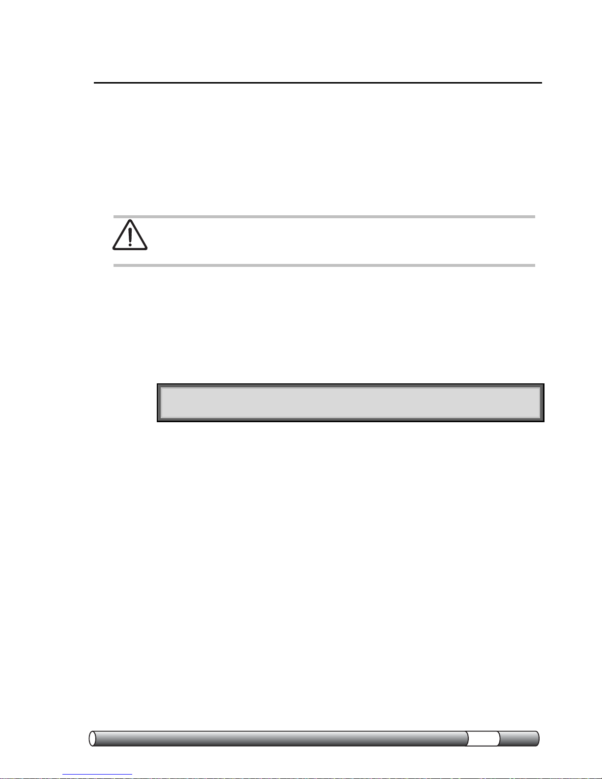
6.1 Description of the control devices
6.1.1 T-DRILL T-60
2 1
3
Control devices: 1. Trigger, 2. Speed selector 3. Feed mechanism
engagement lever
NOTE! Use maximum speed of rotation when drilling and forming the
outlet - when working press the trigger completely down!
16
TEE FORMING MACHINE
17
T-6
0
T
h
e
s
p
e
e
d
s
1. Speed selector
2. The feed mechanism lever
The speed selector knob is on the top of the gearbox of the T-60. Slow
speed is marked “I” and fast speed is marked “II”. To shift from fast to slow
speed, turn the selector knob 180 degrees. Drilling is always done in fast
speed (II). The forming of the tee is done in either slow speed or fast
speed depending on the run tube and outlet sizes. See the chart in
chapter 11.
If the speed selector knob does not engage smoothly, rotate the
motor by “bumping” the trigger.
The feed mechanism lever is situated near the chuck-ring. The feed
mechanism is engaged (on) when the lever is turned downward, i.e. as
shown on the illustration.
If the feed mechanism lever does not engage smoothly, rotate the
motor by “bumping” the trigger.
Do not force lever.

INSTRUCTION MANUAL
6.2 Selection and adjustment of the T-DRILL heads
6.2.1 The identification of the T-DRILL head
The size of the T-DRILL head is stamped on the cover plate:
5310401
15 1/2
1
2
3
Identification: 1. Actual size in millimetres, 2. Nominal size in inches (NS),
3. The ordering and identification number of the T-DRILL head
18

TEE FORMING MACHINE
19
T-6
0
6.2.2 The fine adjustment of the outlet diameter
NOTE! When adjusting the outlet diameter, extend the forming pins first.
Each T-DRILL head is adjusted at the factory to correspond to the nominal
size stamped on the cover of each T-DRILL head. Changing the tube
sizes or the way of joining may require adjustment of the T-DRILL head in
order to achieve the right joint.
To extend the forming pins (1) press
the cover (2) in direction of the
shank. Twist the shank (3) at the
same time clockwise until a positive
stop is reached, and the forming pins
extend.
1
2
3
T
Check the forming pin span diameter T with an adjusting ring or slide
gage.

INSTRUCTION MANUAL
Depending on the size of the T-DRILL head, the forming pin span T should
be 0,020” – 0,055” (0,5 – 1,4mm) bigger than the branch pipe outer
diameter (O.D.)
1. Loosen the screws on the cover
plate by about one circle using a 3
mm hexagon wrench, that is
supplied with the T-DRILL
package.
2. To enlarge the outlet rotate the conical
cover with respect to the cover plate in
plus (+) direction. Hold the cover plate
stationary.
To make a smaller outlet rotate the
conical cover in minus (–) direction while
holding the cover plate stationary.
One
notc
h on the cover-plate equals to 0.01” or
0,25 mm on the forming pin span.
3. Tighten the two screws on the cover
plate and check the adjustment either by
measurement across the pins or by forming
a trial outlet.
20

TEE FORMING MACHINE
T-6
0
6.3 Chucking the T-DRILL head
6.3.1 Chucking
To insert the T-DRILL head into the chuck, rotate the locking ring (1)
clockwise and slide the T-DRILL head shaft into the chuck(2). Release the
locking ring. Rotate the T-DRILL head (3) in the chuck until it locks. Make
sure the T-DRILL head is tightly chucked.
6.3.2 Removal
To remove the T-DRILL head (2) from the chuck (1), rotate the locking ring
as far it will go. Turn the T-DRILL head to the same direction one quarter
of a turn (1/4) at the same time pulling it straight out. Release the lock ring.
2
3
1
Chucking the T-DRILL head and removing it.
21

INSTRUCTION MANUAL
6.3.3 Fitting the old T-DRILL heads to the T-60 –machine
If you have old 42/1½ or 54 /2 T-DRILL heads, you can use them in
T-DRILL T-60 after shortening the drill core as described below. Without
shortening the drill cores of old T-DRILL heads do not fit in the chuck of
the T-60.
6.3.3 Shortening the drill core. The distance between the center line of the
draft hole and the core end has to be 31/32” (25 mm).
22

TEE FORMING MACHINE
T-6
0
6.4 The tee forming process with the T-DRILL T-60
Since the process may be new to you, we recommend that you read the
following instructions carefully and then practice a few times on some
pieces of scrap tubing.
NOTE! Before forming any tee always make sure that the pipe is
completely drained and that it is not under pressure
1. Select the correct T-DRILL head.
2. Check the forming pin span (T). Adjust if necessary. (See chapter
6.2.2).
3. Chuck the T-DRILL head.
4. Lubricate the T-DRILL head
before every tee forming operation!
Extend the forming pins and
lubricate them as well as the
cutting edges of the T-DRILL head
as illustrated. Always use T-
DRILL lubricant.
5. Retract forming pins. Press
the conical cover towards the tool
and rotate it clockwise to retract
the forming pins.
23

INSTRUCTION MANUAL
6. Check that the speed selector knob is in position II and the feed
mechanism lever in “off”-position.
7. Pull the support legs out and place
the tube support firmly onto the point
where the tee is to be formed on the
tube, as shown on the illustration.
Press the tube support with the thumb
against the tube and twist the machine
counterclockwise at the handle of the
tool. This centers the T-DRILL head
onto the tube.
8. Start the tool by pressing the trigger
and drill until the bit has fully
penetrated into the tube. Release the
trigger - the machine will stop.
NOTE! If the tool does not have enough power to drill – select the low
speed I and continue drilling. This may be necessary if a long extension
cord is used.
9. Extend the forming pins on the TDRILL head by pressing the conical
cover towards the tool and rotating it
counterclockwise until the T-DRILL
head locks into the tee forming
position. Do not extend the forming
pins while the motor is running!
24

TEE FORMING MACHINE
T-6
0
10. Select low speed I by turning the
selector knob. (Always use low speed (I)
when forming the outlet, consult
capacity chart in section 11.1 for
options.) Engage the feed mechanism
as shown. If it does not engage
smoothly, rotate the motor by “bumping”
the trigger.
11. Start forming the outlet by pulling
the trigger and continue until the TDRILL head is completely out of the
tube. During the forming of the tee, keep
the tube support against the tube and
push the tool toward the tube. This
insures that you obtain a circular outlet.
12. Once the T-DRILL head has come
completely out of the outlet, release
the trigger.
IMPORTANT! Release the drill trigger as soon as the T-DRILL head
clears the rim of the outlet.
NOTE! Never attempt to “help” the tool by pulling it out of the tube. This
would result in an oval outlet!
NOTE! Wipe away any exess lubricant which may have remained inside
the outlet before brazing. Use sandcloth or Scotchbrite to clean the
inside of the rim of the outlet!
25
INSTRUCTION MANUAL
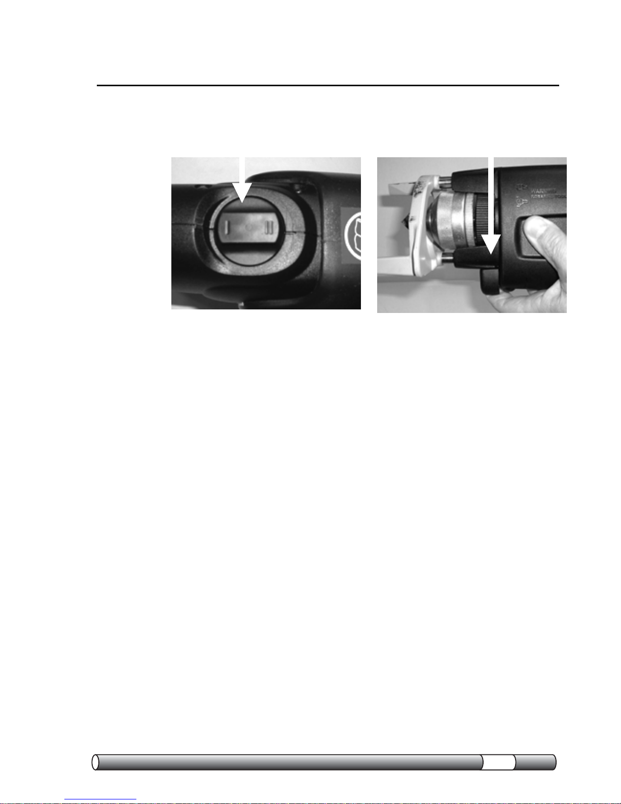
6.5 Annealing of tube
DANGER! The annealed work piece is extremely hot after annealing.
When working with the tube protective gloves should be used.
1. Anneal the area where outlet is to
be formed to a dull red.The area will
remain annealed even when cool. It
is not necessary to form the outlet on
hot tube!
2. Attach counterplate to the tube
where annealing has been done.
3. Lubricate forming pins and cutting
edges on T-DRILL head.
26
TEE FORMING MACHINE
T-6
0
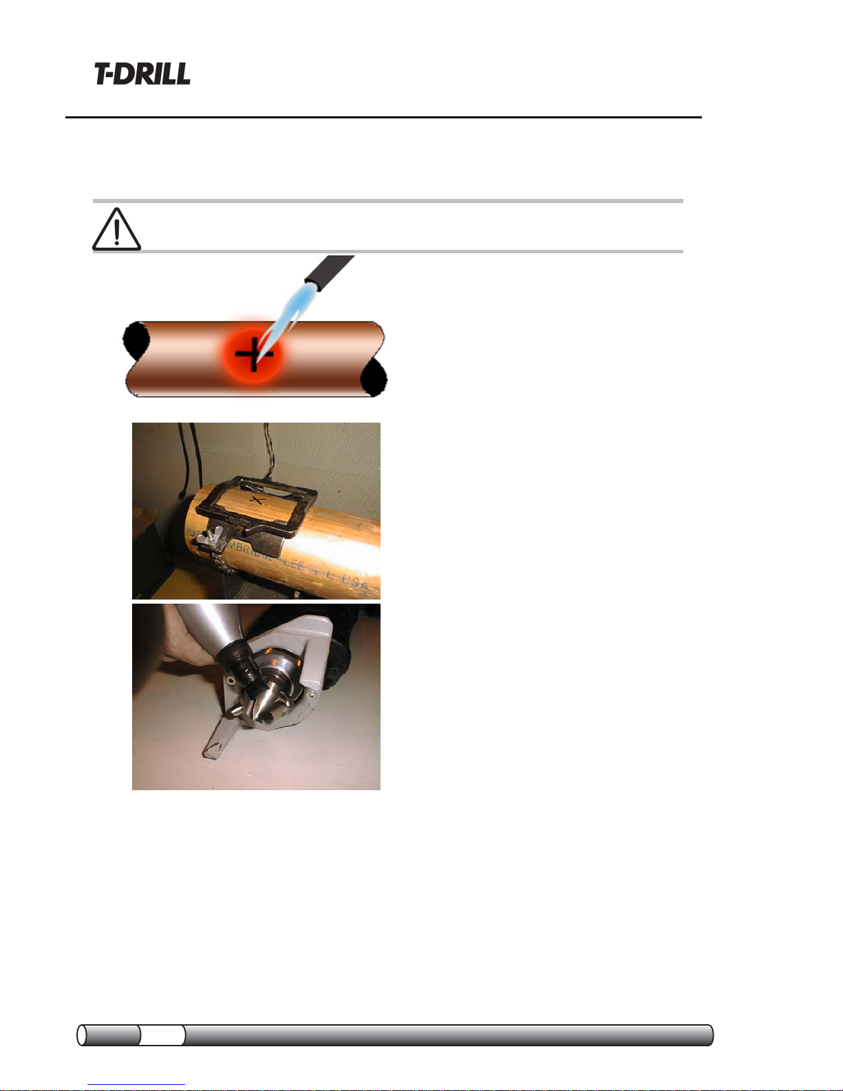
4. Retract forming pins on T-DRILL
Head and attach T-DRILL T-60 to
counterplate. Notches on tube
support fit on tabs of counterplate.
5. Drill pilot hole, extend forming
pins, reduce speed, engage feed
mechanism, pull trigger to form the
outlet. Release trigger when forming
pins clear the rim of the outlet.
6. Notch and dimple both sides of
branch tube.
7. Align dimples with the run of the
tube after insertion into the outlet.
Braze the joint.
27

INSTRUCTION MANUAL
7. Maintenance
7.1 The maintenance of the T-DRILL T-60
The T-DRILL T-60 is prelubricated and does not need special attention for
maintenance. Clean dust and dirt from tool vents.
NOTE! All maintenance operations for the T-DRILL T-60 and
MILWAUKEE power unit sold in North America are to be carried out
only by T-DRILL Industries, Inc. in Norcross, Georgia, USA.
28

TEE FORMING MACHINE
T-6
0
7.2 The replacement of the forming pins
1. Loosen the two screws on the
cover plate one turn and rotate
the conical cover with respect to
the cover plate so that the conical
cover can be removed. When the
conical cover is removed rotate
the cone so that the forming pins
will slide from the shank.
2. The forming pins can now
be changed.
3. Reassemble the T-DRILL
head using new forming pins and
adjust to the right outlet
diameter.
29

INSTRUCTION MANUAL
8. Trouble-shooting
Problem Cause Remedy
The power unit
doesn’t run.
The connection cord loose, or
the plugs do not make contact
with the wires inside the cord.
Trigger not fully pressed.
Insert the cord into the
bracket, or substitute the
cord with a new one.
Press the Trigger fully.
Burrs in the tee that
has been formed
Burrs in the pilot hole
- the drill bit is dull
- lubricant insufficient
- lubricant of bad quality
The forming pins are worn or
dirt stuck on their surface.
Insufficient lubricant during
forming of the outlet.
Lubricant not suitable to the
material
The wall thickness of the tube
exceeds the maximum
allowable thickness.
- Anneal Area to be
drilled
- Change drill bit
- Use more lubricant
- Only lubricant
recommended by
T-DRILL is to be used
Clean or change the
forming pins
Always lubricate the TDRILL head carefully
before every outlet forming
operation
Consult your local T-DRILL
representative
Consult the capacity charts
The size of the tee
varies.
Dirt stuck to the surface or the
holes of the forming pins.
Adjusting screws of the head
are too loose.
Clean the forming pins.
Tighten the screws
30

TEE FORMING MACHINE
T-6
0
Problem Cause Remedy
The forming pins break
off or the drill shank
breaks
Lack of annealling when
called for in instructions.
Burrs in the pilot hole
-drill bit dull
The wall-thickness of the
tube exceeds the max.
allowable thickness.
Not enough lubricant
during forming of the tee.
The lubricant is not
suitable for your
material
Tool is not straight
against the pipe.
Slow speed was not
used when referenced
on the capacity chart.
– Resharpen or change
the drill bit
See the capacity charts.
Lubricate the T-DRILL
head carefully before
forming the outlet.
Consult your local
T-DRILL representative.
Use counterplate. (extra
equipment)
Use slow speed when
indicated on the
capacity chart.
31

INSTRUCTION MANUAL
9. Disposing
Disposing of the T-DRILL machine
In the manufacturing of the T-DRILL machines various kinds of metals,
plastic and lubricants have been used. Dispose of your T-DRILL machine
according to federal, state and local regulations.
32

TEE FORMING MACHINE
T-6
0
10. Warranty
T-DRILL guarantees that every T-DRILL T-60 tee forming machine is free
from defects in materials and workmanship (other than normal wear and
tear) for a period of one (1) year from date of shipment. Should within this
period any T-60 be proved to T-DRILL's satisfaction to be defective, such
product shall be repaired or replaced. Such repair or replacement shall be
T-DRILL’s sole obligation; whereas the buyer's only obligation is to inform
T-DRILL of any such defect. T-DRILL must receive the reclamation in
writing within 10 days after a defect having been noticed and, at
T-DRILL’s option, buyer will have to return the complete tool to the
nearest T-DRILL Representative or Distribution Center. THIS
WARRANTY IS PRIMARY.
T-DRILL’s warranty shall be limited to the aforesaid warranty stipulations.
T-DRILL SHALL NOT BE SUBJECT TO ANY OTHER OBLIGATIONS OR
LIABILITIES, WHETHER ARISING OUT OF BREACH OF CONTRACT,
TORT (INCLUDING NEGLIGENCE) OR OTHER THEORIES OF LAW,
WITH RESPECT TO PRODUCTS SOLD OR SERVICES IMPLICATED,
OR ANY UNDERTAKINGS, ACTS OR OMISSIONS RELATING
THERETO. T-DRILL SHALL NOT BE LIABLE FOR AND DISCLAIMS ALL
CONSEQUENTIAL, INCIDENTIAL AND CONTIGENT DAMAGES
WHATSOEVER.
Please register your purchase by filling out and returning the
warranty registration card enclosed. Save your receipt.
33

INSTRUCTION MANUAL
11. Supplement
Capacity and instruction chart for T-DRILL T-60 on M, L, &
K tubing
Run Tube Size
1
/2” 3/4”
1”
1-1/4” 1-1/2”
2” 2-½” 3” 4”
Nominal
Outlet Size
Notch and dimple all branch tubes. Place dimples in line with the
run of the tube.Braze all joints
1
/2”
3 1 1 1 1 1 5
4
5 4 5
4
3
/4”
3 1 1 1 1 5
4
5
4
5
4
1”
3* 1* 1* 1* 5 5 5
1-1/4”
3 2 2 5 5 5
1-1/2”
3 2 5 5 5
2”
3 5 5 5
= Pre-anneal the area where tee is to be formed or anneal
pilot hole in this section. Form tee at slow speed. Use counter
plate
*
It may be necessary to use reduced speed to form the tee.
1. Apply T-DRILL lube to T-DRILL Head. Extend tube supports, place
tube supports on either side of tube. Drill pilot hole, extend forming
pins, engage feed mechanism, form outlet. Use high speed. Maintain
pressure towards tube as outlet is formed.
2. After drilling pilot hole, extend forming pins, form outlet at reduced
speed. maintain pressure towards tube as outlet is formed.
3. After drilling pilot hole, remove drill by engaging feed mechanism.
Anneal brieflty below each side of pilot hole. Reinsert drill, extend
forming pins and form outlet. It may be necessary to slightly oversize
forming pins to compensate for springback in copper tube wall.
Maintain pressure towards tube as outlet is formed.
4. When a ½“ or ¾“ outlet is needed on 2 ½” , 3” or 4” tube, follow the
directions in Legend 5 but form a 1” outlet and reduce with fitting by
copper reducer. Notch and dimple reducer. Align dimples with the run
of the tube – braze joint.
5. Anneal to a dull red area where outlet will be formed. Attach
counterplate to the tube. Apply T-DRILL lubricant to cutting edges and
forming pins of the T-DRILL Head. Retract forming pins on T-DRILL
Head and attach T-DRILL T-60 to the counterplate, drill pilot hole,
extend the forming pins, reduce speed using the speed selector dial,
34

TEE FORMING MACHINE
T-6
0
engage the feed mechanism, pull the trigger to form outlet. Notch and
dimple branch tube. Insert branch tube into outlet, align dimples with
the run of the tube – braze the joint.
** If motor slows during drilling of pilot hole, shift to slow speed.
NOTE: Lubricate drill bit and forming pins with T-DRILL lubrication on
every outlet. After outlet is formed clean lubricant from inside edge of the
rim with sand cloth or scotchbrite.
Have A Question?
Call Toll Free in USA 1-800-554-2730 Ext. 216
35

INSTRUCTION MANUAL
36
Capacity chart in millimeters
Use the capacity charts to determine the maximum wall-thickness of the
tube and to select the right T-DRILL head.
Instructions for the use of the capacity charts:
1. Use the unit of measure that is correct for you: the measures of the
charts are in both millimeters and in inches.
2. From the horizontal black row, find
the tee size you need (inner
diameter), and from the vertical black
column the outer diameter of your
run tube.
3. The intersection of the horizontal and
vertical rows will show you the
maximum wall-thickness of the tube.
This thickness is not to be exceeded.
Capacity charts for forming tees in copper tubes
Max wall-thicknesses (mm)
10 12 15 18 22 28 35 42 54
1/4” 3/8" 1/2" 5/8" 3/4" 1" 1¼" 1½" 2"
15 1/2" 1.0 1.2 1.2
18 5/8" 1.0 1.2 1.5 1.2
22 3/4" 1.0 1.2 1.5 1.5 1.5
28 1" 1.0 1.2 1.5 1.5 1.5 1.5
35 1¼" 1.0 1.2 1.5 1.5 1.5 1.5 1.5
42 1½" 1.0 1.2 1.5 1.5 1.5 1.5 2.0 2.0
54 2" 1.0 1.2 1.5 1.5 1.5 1.5 2.0 2.0 2.0
64 2½" 1.0 1.2 1.5 1.5 1.5 1.5 2.5 2.5 2.5
76,1 3" 1.0 1.2 1.5 1.5 1.5 1.5 2.5 2.5 2.5
88,9 3½" 1.0 1.2 1.5 1.5 1.5 1.5 2.5 2.5 2.5
108 4" 1.0 1.2 1.5 1.5 1.5 1.5 2.5 2.5 2.5
= Annealing before forming the tee is recommended!

TEE FORMING MACHINE
T-6
0
37

INSTRUCTION MANUAL
38
12. Spare parts list
12.1. T-60
1
6
7
3
2
4
5
8

TEE FORMING MACHINE
T-6
0
12.1. T-60
Part No. Complete Assembly
5330161 T-DRILL T-60 120V US
A
5330163 T-DRILL T-60 230V
Europe
5330110 T-DRILL T-60 110V U
K
5330209 T-DRILL T-60 110V
Item Part No. Description Qty
1 5330158
5330160
5330109
Power Unit 120V USA
Power Unit 230V Europe
Power Unit 110V UK
/Japan
1
2 5330154 T-60 Tee Forming Unit 1
3 2330111 Adapter PUR 1
4 3330032 Tube Support 1
5 9114027 Socket head cap screw 2
6 4330164
4330165
4330108
4330223
Name plate 120V USA
Name plate 230V Europe
Name plate 110V UK
Name plate 110V Japan
1
7 9146622 Sticker, read the instr. 1
8 9048335
9048320
9048342
9048331
Cord 120V USA
Cord 230V Europe
Cord 110V UK
Cord 110V Japan
1
39

INSTRUCTION MANUAL
12.2. The T-60 Tee Forming Unit
14
6
5
18
9
17
16
2
1
18
17
19
15
10
7
23
4
13
21
8
11
9
23
12
40

TEE FORMING MACHINE
T-6
0
Part No. Complete Assembly
5330154 T-60 Tee Forming Unit
Item Part No. Description Qty
1 5330156 Housing 1
2 5330117 Lead Screw 1
3 5330097 Nut Assy Complete 1
4 5540031 Reduction Gear 1
5 3330178 Gear Changer 1
6 5330115 Shift Knob 1
7 4330099 Push Rod 2
8 3330074 Lever 1
9 4540068 Pin 2
10 3330075 Drive Piece 1
11 4540056 Bar 1
12 3300056 Locking Ring 1
13 4300055 Chuck Ring Spring 1
14 4540069 Shaft 1
15 4300054 Chuck Drive Pin 2
16 3540045 Selector Gear 1
17 9026146 Spring 2
18 9018089 Parallel Pin 2
19 9012205 Spring Washer 1
20 9017033 Slot-headed screw 1
21 9018206 Spring Pin 3x8 1
23 9019007 Retaining Ring 2
24 9021006 Groove Ball Bearing
6005 2RS
1
41

INSTRUCTION MANUAL
12.3 T-DRILL Head
7
5
6
3
4
2
1
8
9
6
11
10
2
9
Tee Size ∅ mm
10 12 15 18 22 28 35 42 54
Nominal Tee Size ∅ inch
1/4 3/8 1/2 5/8 3/4 1 1/1/4 1/1/2 2
Order No. 5310399 5310400 5310401 5310402 5310403 5310404 5310411 5310412 5310413
Item Description Qty
Part No.
1 Drill Core 1
2310140 2310150 2310160 2310170 2310180 2310210 4310221 4050253 2050254
2 Forming Pin 2
3310240 3310245 3310250 3310250 4310466 4310467 3430033 3430033 3430034
3 Cone 1
2310283 2310283 2310283 2310283 2310283 2310283 2310451 2310451 2310451
4 Adjustment Plate 1
3310293 3310293 3310297 3310310 3310304 3310304 3310304 3050151 3050151
5 Cover Plate Assembl 1
4310323 4310329 4310335 4310341 4310347 4310359 4310362 4310364 4310365
6 Screw 2
4310372 4310372 4310372 4310372 4310372 4310372 4310372 4310372 4310372
7 Spring 1
4310376 4310376 4310376 4310376 4310376 4310376 4310376 4310376 4310376
8 Conical Cover 1
3310380 3310380 3310380 3310380 3310389 3310389 3050149 3050149 3050149
9 Circlip 2
9019003 9019003 9019003 9019003 9019003 9019003 9019003 9019003 9019003
10 Circlip 1
9019201 9019201 9019201 9019201 9019201 - - - -
11 Pin 1
9018038 9018038 9018038 9018038 9018038 9018038 9018038 9018038 9018038
42

TEE FORMING MACHINE
T-6
0
12.4 Counterplate 5540085
Item Part No. Name Size/Type Std./Manuf. Qty
1 3540011 Counterplate
1
2 3540012 Counter plate mask.
1
3 3540013 Counterplate fem.
1
5 5540201 Chain
1
6 9018038 Parallel pin
Ø3m6x20 DIN 6325 4
7 4540070 Pin
1
12.4.1 Chain 5540201
Item Part No. Name Size/Type Std./Manuf. Qty
1 4050090 Screw
1
2 4540015 Knob
1
3 9013201 Wing nut
M6 DIN 315 1
4 9024117 Coupler link
1/2" Wipperman
332
1
5 9024102 Roller chain
1/2" Wipperman
332 250
DIN 8187 1
43

INSTRUCTION MANUAL
12.5 Optional Equipment
Item Part No. Description Qty
1 5090294 Notcher ND-54 1
2 3310461 Gauge Block 1
3 5540085 Counter Plate 1
5 9010205 Lubricant for Copper
1L-bottle
1
44

TEE FORMING MACHINE
T-6
0
13. Ordering spare parts
When ordering spare parts, please state the following details:
-The type code of the machine
-Manufacturing code of the machine
-The part number
-A description of the part
-The quantity of the parts required
The type code and the manufacturing code of the machine are indicated
on the nameplate of the machine. The other information can be found from
parts list.
For example:
XX: Assembly name 5XXXXXX 2(4)
Item Part No. Designation Std. /Manuf. Qty
33 4800220 Left Hand Slide Gib
3
34 9014313 Flat Head Cap Screw M5x8
DIN7991
12
37 3801440 Lever
2
38 4800276 Rod Eye
1
39 4800299 Clamp Ring
4
1 2 3
1. Part number 2. Description 3. Quantity
When ordering spare parts, make a copy of the Service Sheet, fill it out
and fax or mail it.
To proceeding this way you will prevent misunderstandings and you make
sure to receive the correct spare parts and a prompt service.
45

INSTRUCTION MANUAL
INSTRUCTION MANUAL
46 46
 Loading...