

INSTALLATION INSTRUCTIONS
Please follow these instructions to ensure the proper operation of your T & D MACHINE
PRODUCTS Chrysler B-1 Rocker Arm Assembly with 5/8" diameter rocker shafts.
1. CYLINDER HEAD INSPECTION AND PREPARATION
Inspect the cylinder heads to be sure they are clean and free of any burrs that may
interfere with the rocker stands. Inspect the tapped holes for proper thread depth.
Minimum thread depth is 3/4". This rocker system is designed to oil through the
pushrods, so the block and lifters must be modified accordingly. Also, the oil
supply holes in the cylinder head must be plugged to prevent leaking by tapping the
oil holes for a 12-24 set screw.
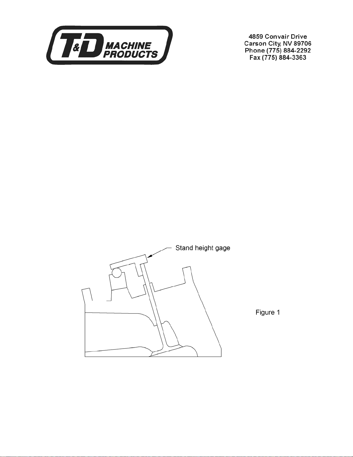
2. DETERMINE CORRECT STAND HEIGHT
Install the rocker stands on the cylinder head using the 3/8-16, 12 point attaching
bolts. Remove a rocker arm from one of the shafts and place that shaft on a
stand. Take the shaft height gage supplied with the kit and place it on the valve
stem as shown in Figure 1.
The gage should contact the top of the valve and the rocker shaft as shown in
Figure 1.
If the gage contacts the shaft before touching the top of the valve stem, as shown
in Figure 2, remove a corresponding amount of material from the stud bosses on
the cylinder head. This will lower the rocker stand on the cylinder head.
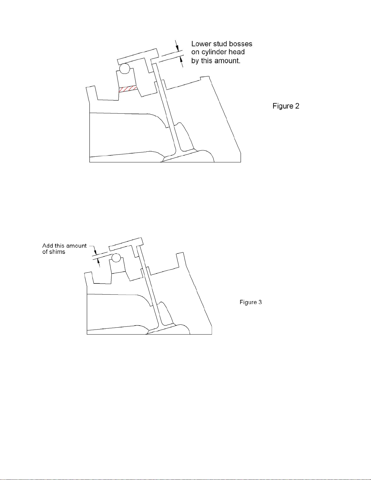
If the gage contacts the top of the valve stem and does not touch the rocker shaft,
as shown in Figure 3, add a corresponding amount of shims between the stand
and the cylinder head. This will raise the rocker stand and shaft to the correct
height.
4. DETERMINE CORRECT PUSHROD LENGTH
Place a pushrod length checker into the lifter and install the rocker arm assemblies.
Be sure the cam is rotated to the base circle. Seat the bottom of the adjuster screw
up against the recess in the rocker arm and turn the adjuster screw clockwise one
full turn down. This is the initial adjuster position. Adjust the pushrod length tool to
the proper length, remove from the engine, and measure its overall length.

The rocker arm should not be operated with the adjuster screw more than one turn
up or down, from the initial adjuster position. Doing so can cut off the flow of oil to
the rocker arm.
5. FINAL ASSEMBLY
After all of the stand heights have been set, place a rocker and shaft back on the
stand to assure good rocker to valve alignment and torque the stand attaching bolts
to 50/55 ft-lbs. Install the 5/16 studs and torque them to 50 inch-pounds. When the
stands are aligned and tightened down, place the rocker arm and shaft assemblies
on the stands and tighten the shaft hold down nuts to 25 ft-lbs. After all of the
rockers have been tightened down, set valve lash and torque the adjuster screw
jam nut to 5/20 ft-lbs.
 Loading...