

Page 1
TPS3000 SERIES
POWER SUPPLY
OPERATION MANUAL
GENERAL SAFETY INSTRUCTIONS ........................................................................................................ 2
High Voltage Warning ................................................................................................................................ 2
Critical Components ................................................................................................................................... 2
Servicing ..................................................................................................................................................... 2
Safety Class of Protection........................................................................................................................... 2
Installation .................................................................................................................................................. 2
Ratings, Specifications and Features .............................................................................................................. 4
Emissions.................................................................................................................................................... 4
Immunity .................................................................................................................................................... 4
Maximum Ratings ...................................................................................................................................... 5
Input Specifications .................................................................................................................................... 5
Output Performance Specifications ............................................................................................................ 6
Protective Functions ................................................................................................................................... 6
Operating Modes ........................................................................................................................................ 6
DC Output Controls and Indicators ............................................................................................................ 7
Remote Control Features ............................................................................................................................ 7
PMBus Features.......................................................................................................................................... 8
Input, Output and Signal Connections ........................................................................................................ 8
Signal Connector ........................................................................................................................................ 9
Local Sense Setup...................................................................................................................................... 11
Remote Sense Setup .................................................................................................................................. 11
Parallel Operation Setup ............................................................................................................................12
Series Operation Setup ..............................................................................................................................14
Ripple and Noise Notes .................................................................................................................................16
Mechanical Drawing .....................................................................................................................................17
PMBus Interface ............................................................................................................................................18
1
30 July 2019
Page 2

GENERAL SAFETY INSTRUCTIONS
TPS3000 SERIES
POWER SUPPLY
OPERATION MANUAL
High Voltage Warning
Dangerous voltages are present within the power supply.
Critical Components
This product is not authorized for use as a critical component in nuclear control systems, life support systems
or equipment for use in hazardous environments without the express written approval of the Engineering
Director of TDK-Lambda Americas.
Servicing
This product is not customer serviceable.
Unit repairs shall only be carried out by TDK- Lambda Americas or their Authorized agents.
Contact: TDK-Lambda Americas
401 Mile of Cars Way, Suite 325
National City, CA 91950
Tel 619-575-4400
Fax 619-575-7185
Safety Class of Protection
The unit is designed for the following parameters: Material Group IIIb, Pollution Degree 2, Overvoltage
Category II, Class 1 (earthed), Indoor use. The unit is considered as fixed and rated IPX0. The TPS300024
and TPS300048 are classed as having SELV outputs. All outputs are capable of providing hazardous energy
(>240VA). The final equipment should provide protection to service personnel against inadvertent contact
with the PSU output terminals.
Installation
This product is designed for use within other equipment which restricts access to Authorized competent
personnel only. The unit covers/chassis must not be made user accessible.
The appliance may be mounted in any orientation.
The mains input connector is not acceptable for use as field wiring terminals.
The appliance must be securely mounted and earthed before any connection to AC mains supply is made.
The ventilation openings must not be impeded – ensure a space at least 5cm between any obstruction and the
ventilation openings.
BEFORE USING THE POWER SUPPLY UNIT
Be sure to read this instruction manual thoroughly before using this product. Pay attention to all cautions and
warnings before using this product. Incorrect usage could lead to an electrical shock, damage to the unit or a
fire hazard.
DANGER
Never use this product in locations where flammable gas or ignitable substances are present.
WARNING
Do not make unauthorized changes to power supply unit, otherwise you might have electric shock and
void your warranty.
Do not touch this unit and the internal components in operation or shortly after shut down. They might
have high voltage or high temperature and as the unit dissipates its heat so the surface of the unit is hot. You
might receive electric shock or burn.
When the unit is operating, keep your hands and face away from it; you might be injured by an accident.
Do not use unit under unusual conditions such as emission of smoke or abnormal smell and sound etc.
It might cause fire and electric shock. In such case, please contact us; do not repair by yourself, as it is
dangerous for the user.
2
30 July 2019
Page 3

TPS3000 SERIES
POWER SUPPLY
OPERATION MANUAL
Do not drop or insert anything into unit. It might cause failure and fire.
Do not operate these units under condensation condition. It might cause fire and electric shock.
CAUTION
As a component part, compliance with the standard will be based upon installation in the final
application. This product must be installed in a restricted access location, accessible to authorized competent
personnel only. These AC to DC converters have reinforced insulation between the input and the output. The
outputs of these products are energy hazards. The equipment has been evaluated for use in a Pollution Degree
2 environment.
This product is designed for use within other equipment or enclosures which restrict access to authorized
competent personnel only and must not be user accessible. Confirm connections to input/output terminals
and signal terminals are correct as indicated in the instruction manual.
Input voltage, Output current, Output power, ambient temperature and ambient humidity should be used
within specifications, otherwise the unit will be damaged.
For application equipment, which requires very high reliability (Nuclear related equipment, traffic
control equipment, medical equipment, etc.), please provide fail safety function in the equipment.
Do not use the product in environment with strong electromagnetic field, corrosive gas and conductive
substance.
Do not operate and store this unit at an environment where condensation occurs. In such case, waterproof
treatment is necessary
Never operate the unit under over current or shorted conditions for 30 seconds or more and out of Input
Voltage Range as specification. Insulation failure, smoking, burning or other damage might occur to the unit.
The output voltage of this power supply unit is considered to be a hazardous energy level (The voltage
is 2V or more and the electric power is 240VA or more). Prevention from direct contact with output terminal
is highly necessary. While installing or servicing this power supply unit, avoid dropping tools by mistake or
direct contact with output terminal. This might cause an electrical shock. While repairing this power supply
unit, the AC input power must be switched off and the input and output voltage should be level.
To maintain the SELV output, under fault conditions, the output must be connected to earth in the final
application.
The application circuits and their parameter are for reference only. Be sure to verify effectiveness of
application circuits and their parameters before finalizing circuit design.
Do not inject abnormal voltage to output terminal and signal terminal from the outside. The injection of
reverse voltage or over voltage exceeding nominal output voltage to output terminals might cause damage to
internal components.
This information in this document is subject to change without prior notice. For actual design-in, please
refer to the latest publications of data sheet, etc., for the most up-to date specifications of the unit.
3
30 July 2019
Page 4

OPERATION MANUAL
AC Line Conducted Emissions
Conducted RF Common Mode
Power Frequency Magnetic
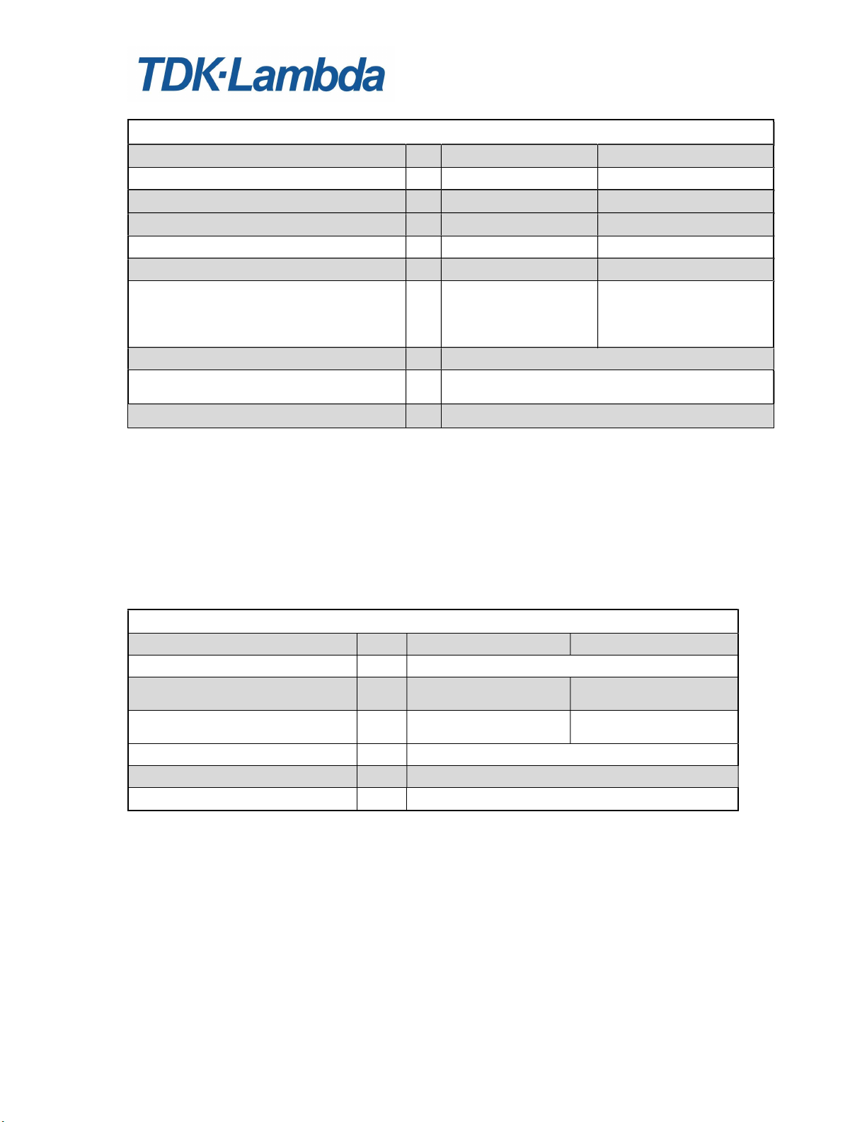
Ratings, Specifications and Features
Emissions
EN 55022: 2010+AC: 2011 (0.15-30 MHz) Class A
Radiated RF Emissions EN55032/EN55022/ EN55011 0-1000 MHz Class A
Immunity
Electrostatic Discharge IEC61000-4-2: 2008 +/-8 kV Air
+/-4 kV Contact
TPS3000 SERIES
POWER SUPPLY
RF Radiated Fields EN 61000-4-3: 2006
+A1:2008 +A2:2010
Electrical Fast Transients EN61000-4-4: 2004+A1:2010 Power line pulses of ± 1 kV;
Lightning Surge IEC61000-4-5: 2005 ±4kV common mode,
EN61000-4-6: 2009 150 kHz - 80 MHz at 3 Vrms
IEC61000-4-8:2009 30A/m (Continuous), 300A/m (Short)
Field
Voltage Dips/Short Variations IEC61000-4-11:2004 5% of nom. line for .5 cycles - Criteria B
Voltage Dips/Short Variations SEMI F47-0706 50% of nom. line for 10 cycles - Criteria B
3 V/m from 80-1000 MHz
(80% AM at 1kHz)
I/O line pulses of ± 0.5 kV
±2kV differential mode
1 kHz 80% amplitude modulated
70% for 25 cycles - Criteria B
40% for 5 cycles - Criteria B
95% Dip for 5 seconds - Criteria B
70% for 25 cycles - Criteria B
80% for 50 cycles - Criteria B
0% for 1 cycle - Criteria B
80% for 10 seconds - Criteria B
95% Dip for 5 seconds - Criteria B
Table 1
4
30 July 2019
Page 5
TPS3000 SERIES
Units
A(W)
A(W)
A(W)
A(W)
A(W)
POWER SUPPLY
OPERATION MANUAL
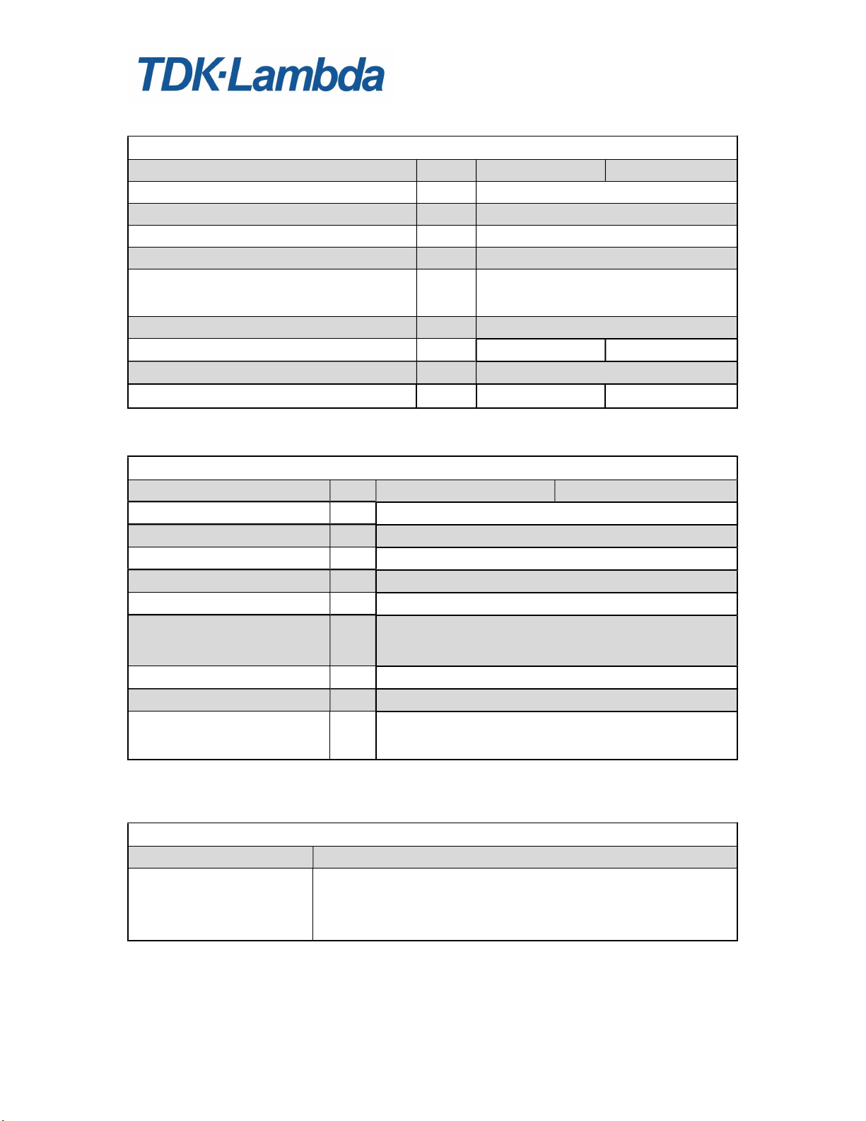
Maximum Ratings
Output Voltage Range1 V 19.5-28.5 38.4-56.5
Maximum Output Current (Power) @ 50°C2
Maximum Output Current (Power) @ 50°C3
Maximum Output Current (Power) @ 60°C3
Maximum Output Current (Power) @ 70°C3
Maximum Output Power with Dropped Phase4
53.75(1290W @ 350VAC)
81.25(1950W @ 480VAC)
Minimum Current5 A 0.5
Operating Temperature °C -10°C to 50°C.
Start-up Temperature °C -40°C to +70°C
1
Output voltage can be adjusted to be outside of the specified range. It is advised to limit the voltage to within the range.
2
Output adjustment at 24V only. Horizontal Mounting configuration only
3
Output current and power, as measured at output terminals, must be less than or equal to quoted maximum values for a
given ambient temperature.
4
Unit is able to handle the specified output power during dropped phase. Other specifications may not be met. Dropped
phase should only be a temporary condition. Prolonged operation under dropped phase may result in decreased lifespan
of the product.
5
Minimum current must be applied to meet all specifications. Without minimum power, some specifications may not be
met.
Input Specifications
Units
Input Voltage VAC 400/480 (50/60Hz) Three Phase Delta
Input Current (RMS) Per Phase
400-480VAC input
Inrush Current (Peak, at cold start)
Per Phase, 400-480VAC input
*
Power Factor (at max output power) - 0.92 typical @ 400/480VAC line
Input EMI Conducted Emissions - FCC Class A, CISPR 22 Class A
Efficiency (at max output power) % 92 typical @ 400/480VAC line
*
excluding initial spike charging EMI capacitors lasting <2mS
A 5.5 5.5
A <15 <15
TPS300024 TPS300048
133.3(3200) 66.7(3200)
125(3000) 66.7(3200)
100(2400) 50(2400)
68.75(1650) 34.375(1650)
26.875(1290W @ 350VAC)
65(1560W @ 400VAC)
32.5(1560W @ 400VAC)
40.625(1950W @ 480VAC)
87.5(2100W @ 528VAC)
43.75(2100W @ 528VAC)
Derating 50°C-60°C - 2%/C, 60°C-70°C 2.5%/C
TPS300024 TPS300048
Table 2
Table 3
5
30 July 2019
Page 6
TPS3000 SERIES
POWER SUPPLY
OPERATION MANUAL
Output Performance Specifications
Units TPS300024 TPS300048
Max Voltage Line Regulation % Less than 0.25%
Max Voltage Load Regulation % Less than 0.5%
Total Regulation % Less than 1.75%
Warm up Drift % Less than 0.15%
Temperature Stability - 0.05% of rated Vout for 8hrs after 30min
warm-up. Constant line, load & temp.
Temperature Coefficient ppm/°C 200ppm/C
Ripple/Noise P-P(20MHz), JEITA RC-9131C6 mVp-p 240 480
Output Ripple, JEITA RC-9131C6 mVrms <0.5% of Vout
Remote Sense Compensation (Total) V 1.0V 1.0V
6
See Ripple and Noise Notes for Details on Jeita RC-9131C method; All Three Phases present
Table 4
Protective Functions
Units TPS300024 TPS300048
OCP TYPE - CONSTANT CURRENT
OCP KNEE POINT7 - Adjustable (70% - 105% of max rated current)
KNEE POINT PROTECTION - NONE. NO DAMAGE AT KNEE POINT
S/C PROTECTION - CONSTANT CURRENT w/ time-delayed shutdown.
SHORTED OUTPUT ON - NO DAMAGE
OVP TYPE - Tracking, Inverter shut-down, manual reset by AC input
recycle or by On/Off control.
OVP RANGE - Vout*1.15
OVP RESET TIME s Less than 5s AC recycle or remote ON/OFF toggle
OTP - Yes. Standard: Non-Latch type (automatic reset),
7
OCP Knee point can physically be adjusted to a value greater than 105% of max rated current. It is advised to limit the
current to 105% max.
Table 5
Operating Modes
Series Operation Yes
Parallel Operation Current share single wire (Terminal 1 on Signal Connector), 10%
accuracy of max Iout up to 8 units. Power derated 10% of rated.
No Oring diodes are required for redundant operation as the
power supplies contain internal Oring MOSFETS.
Table 6
6
30 July 2019
Page 7

TPS3000 SERIES
POWER SUPPLY
OPERATION MANUAL
DC Output Controls and Indicators
Output Voltage Adjust Screwdriver adjustment over entire range. Output voltage range is
specified in Table 2. (Multi-turn potentiometer accessible from
terminal end of chassis.)
Overcurrent Protection Adjust Screwdriver adjustable (70% - 105% of max rated current)
DC OK LED: Green when output >90% of set voltage, Red when fault.
LED will turn off when unit enters OTW range.
AC ON LED: Green when AC is present
Blinking RED/GRN when phase dropped (Applicable for 400/480
with 20% Load or greater).
Table 7
Remote Control Features
Remote Voltage Sensing Provides precise regulation directly at load. Maximum total DC voltage
drop between output terminals and load must be limited to <1.0 V. In
addition, the voltage at the output terminals must be limited to the
maximum voltage range specified in Table 2.
Remote On/Off Control On/Off control: Selectable Enable or Inhibit via front panel switch.
Switch in the ON position: Unit powers up if PSON left open; Unit in
standby mode if PSON shorted to -SNS
Switch in the OFF position: Unit in standby mode if PSON left open;
Unit powers up if PSON shorted to -SNS
PSON High / Low thresholds: 3.0V / 0.6V
12V Maximum allowable.
-5V Minimum allowable
Signal applied between terminals 14 (PSON) and 18 (-SNS) on Signal
Connector.
Remote Voltage
Programming
Remote Overcurrent Limit
Programming
Provides remote adjustment of the output voltage via a DC voltage
applied between terminals 3 (VADJ) and 18 (-SNS) on Signal
Connector.
0V = Vout max, 5V = Vout min
Adjustments of greater than 1V/Sec can cause Fault conditions
Adjustment range changes with adjustment of V
Provides remote adjustment of the Overcurrent limit via a DC voltage
applied between terminals 10 (IADJ) and 18 (-SNS) on Signal
Connector.
0V = Iout max, 5V = Iout min
Adjustment range changes with adjustment of I
Adj trim pot.
out
ADj trim pot.
LIMIT
Table 8
7
30 July 2019
Page 8

TPS3000 SERIES
POWER SUPPLY
OPERATION MANUAL
PMBus Features
Output Voltage Monitoring Output voltage monitoring via the PMBus.
Accuracy of the voltage reading is +/-2% of full scale
Output Current Monitoring Output current monitoring via the PMBus.
Accuracy of the current reading is +/-10% of full scale
Remote On/Off Control Supply ON/OFF control via the PMBus
Remote Voltage
Programming
Remote Overcurrent Limit
Programming
Input, Output and Signal Connections
Input Heavy Duty terminal block with M4 screws. Grounding terminal
DC Output Heavy-duty bus bars with 9mm clearance hole for load connections.
Signal Connector 20 pin signal connector. See Table 11 for pin configuration
Address Pin / PMBus Voltage
Selector Pin
Provides remote adjustment of the output voltage via the PMBus
interface.
Adjustments of greater than 1V/Sec can cause Fault conditions
Provides remote adjustment of the Overcurrent limit via the PMBus
interface.
Table 9
included on terminal block.
Recommended mating connector: JST P/N: PHDR-20VS
Recommended receptacle contacts: JST P/N: SPHD-001T-P0.5
10 pin connector.
Rows 1-4 used for PMBus address selection.
Row 5 used to select PMBus Voltage Selection. Open = 5V; Short = 3.3V
Recommended shunt jumper: Samtec P/N: 2SN-BK-G
Table 10
8
30 July 2019
Page 9

TPS3000 SERIES
POWER SUPPLY
OPERATION MANUAL
Signal Connector
Name Terminal
Location
ISHARE 1 Current share single wire.
Iout 2 Current monitor signal.
VADJ 3 Remote Voltage Programming Terminal.
SDA 4 Data Line for I2C
OTW 5 Over Temperature Warning
SCL 6 Clock Line for I2C
RTN (OTW) 7 Return for Terminal 5
SMB ALERT 8 Interrupt Line for I2C
PHASE OK 9 Open collector. Max. sink current: 5mA.
IADJ 10 Provides remote adjustment of the overcurrent limit via an applied DC
RTN (PHASE OK) 11 Return for Terminal 9
SMB GND 12 Return for I2C (Terminal 4, Terminal 6 and Terminal 8)
RTN (AC OK) 13 Return for Terminal 15
PSON 14 Remote On/Off control. See Remote Control Features section for
ACOK 15 On when Vin>340Vac AND unit enabled. Turns off 5mS before DC
+SNS 16 Positive Sense. Used for remote sense connection.
DC OK 17 Conducts when Vout is greater than 90% of the set output voltage
-SNS 18 Negative Sense. Used for remote sense connection. Analog Signals
RTN (DC OK) 19 Return for Terminal 17
+12V 20 Auxiliary Power Supply: 11.2-12.5V, 0-0.3A. Less than 200mVp-p
Description
0V = Iout min, 5V = Iout max.
Terminal 18 used for Return.
Terminal 18 used for Return.
Provides remote adjustment of Output Voltage via an applied DC
voltage
0V = Vout max, 5V = Vout min.
Open collector. Non Polarized, 60V peak,
Max. sink current: 5mADC. 2Ω ON resistance, Isolated
Terminal 7 used for Return.
Off (open) when OK, strobing when input phase missing
(Applicable for 400/480 with 20% Load or greater).
Open collector. Non Polarized, 60V peak,
Max. sink current: 5mADC. 2Ω ON resistance, Isolated
voltage.
0V = Iout max, 5V = Iout min
Terminal 18 used for Return.
additional details.
Terminal 18 used for Return.
FAIL at nominal Vout, 80% of rated load.
Open collector. Non Polarized, 60V peak,
Max. sink current: 5mADC. 2Ω ON resistance, Isolated
Isolated
(Tracking)
Open collector. Non Polarized, 60V peak,
Max. sink current: 5mADC. 2Ω ON resistance, Isolated
return
ripple and noise.
9
30 July 2019
Page 10

TPS3000 SERIES
POWER SUPPLY
OPERATION MANUAL
Table 11
Figure 1: Pin assignments
10
30 July 2019
Page 11

Local Sense Setup
TPS3000 SERIES
POWER SUPPLY
OPERATION MANUAL
Remote Sense Setup
Figure 2: Typical Local Sense Connection
Figure 3: Typical Remote Sense Connection
* Suitable Decoupling Capacitor (0.1uF or higher) may be required at load.
11
30 July 2019
Page 12

Parallel Operation Setup
TPS3000 SERIES
POWER SUPPLY
OPERATION MANUAL
Figure 4: Parallel Operation (Local Sensing)
*Suitable Decoupling Capacitor (0.1uF or higher) may be required at load.
For optimal performance, power supplies should have their output voltages set to within 1% of each other
12
30 July 2019
Page 13

TPS3000 SERIES
POWER SUPPLY
OPERATION MANUAL
Figure 5: Parallel Operation (Remote Sensing)
*Suitable Decoupling Capacitor (0.1uF or higher) may be required at load.
For optimal performance, power supplies should have their output voltages set to within 1% of each other
13
30 July 2019
Page 14

Series Operation Setup
TPS3000 SERIES
POWER SUPPLY
OPERATION MANUAL
Figure 6: Series Operation (Local Sensing)
*Suitable Decoupling Capacitor (0.1uF or higher) may be required at load.
Note: It is recommended that diodes rated a minimum of 50V be used for any TPS3000-24 units operated in
series and diodes rated at a minimum of 100V be used for any TPS3000-48 units operated in series.
14
30 July 2019
Page 15

TPS3000 SERIES
POWER SUPPLY
OPERATION MANUAL
Figure 7: Series Operation (Remote Sensing)
*Suitable Decoupling Capacitor (0.1uF or higher) may be required at load.
Note: It is recommended that diodes rated a minimum of 50V be used for any TPS3000-24 units operated in
series and diodes rated at a minimum of 100V be used for any TPS3000-48 units operated in series.
DO NOT CONNECT THE SENSE WIRES IN PARALLEL DURING SERIES OPERATION – THIS MAY
RESULT IN DAMAGE TO THE POWER SUPPLY.
15
30 July 2019
Page 16

TPS3000 SERIES
POWER SUPPLY
OPERATION MANUAL
Ripple and Noise Notes
Ripple and Noise is measured according to the description below in accordance with JEITA RC-9131C
(Sections 7.16, 7.17 and 7.18).
The measurement connection is shown in Fig. 3-1.
C1 (0.1µF Ceramic Capacitor), C2 (47uF Aluminum Electrolytic Capacitor) must be connected in parallel at
30cm from the output terminals, along the load cable. Attach a maximum 1.5m 50Ω coaxial cable from the
ceramic capacitor electrodes to a filter attachment installed on the oscilloscope. The filter attachment consists
of C3 (4700pF film capacitor) in series with R (50Ω resistor). Use 100MHz bandwidth oscilloscope or
equivalent.
In general, output ripple voltage and output spike noise voltage can be reduced by increasing external
capacitance.
Figure 8: Output Ripple Voltage (including Spike Noise) Measurement Method
16
30 July 2019
Page 17

Mechanical Drawing
Overall dimensions for the TPS3000 series are shown below:
TPS3000 SERIES
POWER SUPPLY
OPERATION MANUAL
17
30 July 2019
Page 18

TPS3000 SERIES
POWER SUPPLY
OPERATION MANUAL
PMBus Interface
The TPS3000 has Power Management Bus (PMBus) hardware.
The PMBUS interface in the TPS3000 includes:
Monitoring the Output Voltage (+/- 2% of Full Scale).
Monitoring the Output Current (+/- 10% of Full Scale).
Monitoring the Internal Temperature (Works on +40°C to 106°C range. Above 106°C the OTP activates and the
monitor reads ~180°C) .
Programming the Output Voltage (+/- 2% of Full Scale).
Programming the Current Limit
Programming the Supply ON/OFF.
Reading and Clearing Faults.
Reading the Manufacturing Related Data (Model Name, Serial No, Manufacturing Date, etc).
ATTENTION:
The PMBus supports:
100 KHz Operation.
Block Read Protocol.
Group Command Protocol.
Direct Command Format for Monitoring and Programming
Functions. Ver. 1.1 of PMBus Specifications.
18
30 July 2019
Page 19

TPS3000 SERIES
POWER SUPPLY
OPERATION MANUAL
ADDRESSING (A3, A2, A1, A0 inputs)
To communicate with the TPS3000, the master must first address the slave devices via a slave address byte. The slave
address byte consists of seven address bits and a direction bit that indicates the intent to execute a read or write operation.
The TPS3000 features four variable address lines that allow up to 16 Supplies to be connected on a single bus.
PMBus uses 7 bit addressing. There is constant part of address and variable part of address:
Constant part of address consists of 3 Most Significant Bits A6, A5, and A4 and always equals 010.
Variable part of address consists of 4 Least Significant bits: A3, A2, A1, and A0.
These four bits are assigned using the hardware connections of the PS address connector.
The Address lines (A3, A2, A1, and A0) are internally pulled up by resistors to +5V.
The address lines can be left open for ‹1› address or connected for ‹0› address.
The Address Space contains these 16 possible addresses:
R/W
A6 A5 A4 A3 A2 A1 A0
0 1 0 0 0 0 0 x 40h
0 1 0 0 0 0 1 x 42h
0 1 0 0 0 1 0 x 44h
0 1 0 0 0 1 1 x 46h
0 1 0 0 1 0 0 x 48h
0 1 0 0 1 0 1 x 4Ah
0 1 0 0 1 1 0 x 4Ch
0 1 0 0 1 1 1 x 4Eh
0 1 0 1 0 0 0 x 50h
0 1 0 1 0 0 1 x 52h
0 1 0 1 0 1 0 x 54h
0 1 0 1 0 1 1 x 56h
0 1 0 1 1 0 0 x 58h
0 1 0 1 1 0 1 x 5Ah
0 1 0 1 1 1 0 x 5Ch
0 1 0 1 1 1 1 x 5Eh
In case more than one unit is connected to PMBus, each unit must be set to its own unique address. Duplicate addressing
is not allowed.
Note: The TPS3000 is always considered a slave device.
SERIAL CLOCK (SCL)
This line is clocked by the Master which controls the PMBUS. It is connected to +5.0V or +3.3V (referenced to “SMB
GND”) via a 5.0kΩ pull-up resistor.
Byte Hex Address
SERIAL DATA (SDA)
This is a Bi-Directional line which is connected to +5.0V or +3.3V (referenced to "SMB GND") via a 5.0kΩ pull up resistor.
ALERT
ALERT is used to indicate to the HOST about any Faults/Error/Warning Conditions.
This line is connected to +5.0V or +3.3V(referenced to "SMB GND") via a 3.0kΩ pull up resistor.
This Signal is HIGH to indicate that no fault/error/warning is present. If some fault/error/warning occurs, the signal will
go LOW.
The Host system must poll multiple supplies after receiving ALERT to retrieve fault/error/warning information.
Note: The TPS3000 does not respond to Alert Response Address.
19
30 July 2019
Page 20

TPS3000 SERIES
OVP
Output
Voltage
>
1.15xVset
limit.
FANOK
Output
ON
POWER SUPPLY
OPERATION MANUAL
PMBus COMMAND SET
READ_STATUS
This Command is used to read the status of the Power Supply. The Status information is stored in a special register called
the “STATUS REGISTER”
The PMBus reads 16 different types of Faults and Warnings.
Fault is indicated by “1”. No fault is indicated by”0”.
Faults
Low Byte
DCOK
OTP
OTW
ACOK
IPOK
High Byte
IDR
IPM
IOM
I2C_BE
ICPDR
IVPDR
ICR
For Example: If DC Status occurs, READ_STATUS will return 01h. ALERT will go “LOW”
*
Note: There can be a delay of several seconds from the time the fault occurs and the time the status bit updates.
Command Used
D0h
Read
Type
FAULT
FAULT
FAULT
WARNING
*
*
WARNING
FAULT
WARNING 7
0
WARNING 1
WARNING 2
WARNING 3
WARNING 4
WARNING 5
WARNING 6
WARNING 7
Bit # in Status
Register
5
0
1
2
3
4
6
Type
Output Voltage < 85~95% of Set Vout
Internal temperature higher than safe
Internal temperature ~ 10°C below OTP
Fan is rotating slow
Input Voltage <250Vac
One Input Phase Low or Out
Invalid Data Byte Received
Invalid Programming Mode
Invalid Operating Mode
Buss Error
Invalid Current Prog. Data Received
Invalid Voltage Prog. Data Received
Invalid Command Received
#Data bytes
Meaning
2
limit
Main output
behavior
Output ON or
OFF
Output OFF
Output OFF
Output ON
Output OFF
Output ON
Output ON
Output ON
Output ON
Output ON
Output ON
Output ON
Output ON
Output ON
20
30 July 2019
Page 21

TPS3000 SERIES
POWER SUPPLY
OPERATION MANUAL
CLEAR_FAULTS
This command is used to clear the “STATUS REGISTER” after any fault occurs.
If the CLEAR_FAULTS command is not sent after any fault occurs, the “STATUS REGISTER” will not be cleared.
ALERT signal will remain “LOW” until a “CLEAR_FAULTS” command is sent.
If a Fault or Warning is still present after “CLEAR_FAULTS” is sent, “STATUS REGISTER” will be updated and the
ALERT signal will be “LOW” again.
Command code
03h Send Byte 0
OPERATION MODE
This command is used to set the way the user Enables/Disables the output of the Unit. Setting the Operation Mode to
“Remote Mode” allows the user to control the output using the “OPERATION ON/OFF” command via the I2C. In the
“Local Mode” the user has the option to use the Front Panel Output Enable Switch or the “PSON” pin on the Signals
connector.
Command code
D8h R/W Byte 00h=Remote
D8h R/W Byte 80h=Local
When the user switches from “Local Mode” to “Remote Mode” for first time after applying AC power, the default
Operation State will be “Operation ON”. To keep the unit OFF when switching to “Remote Mode”, the “Operation OFF”
command must be sent immediately after entering “Remote Mode”.
If the user tries to change Operation State before the user changes Operation Mode to “Remote Mode” the unit will respond
with error and will ignore the command.
Type
Type
#Data bytes
Data sent
21
30 July 2019
Page 22

TPS3000 SERIES
POWER SUPPLY
OPERATION MANUAL
OPERATION (ON/OFF)
If the Power Supply is turned OFF with the “OPERATION OFF” command, the Supply can be turned ON with the
“OPERATION ON” command.
Command code
01h
01h
After applying AC power to the unit the default control mode is the “Local Mode”.
In this Mode the Front Panel Output Enable Switch will control the output state.
To turn ON or OFF the Unit in “Remote Mode” (I2C) do the following:
Set Operation Mode to “Remote Mode”.
Then issue “Operation ON” to turn ON or “Operation OFF” to turn OFF the unit.
Once the user enters “Remote Mode” the Front Panel Output Enable Switch has no longer control of the Output until the
user changes over to “Local Mode”.
Attention: If the unit is ON and the user issues “Operation OFF” follow by “Operation ON” command within 3.0 Sec,
the Unit will remain in the OFF state for 3.0 Sec from the time the user issue the “Operation OFF” command.
Also in Local Mode the Front Panel Output Enable Switch will behave in the same way. If the unit was enabled and the
User disable it follow by Enable within 3.0 Sec, the Unit will remain in the OFF state for 3.0 Sec from the time the user
disabled the unit.
When the user switches from “Local Mode” to “Remote Mode” for first time after applying AC power, the default
Operation State will be “Operation ON”. To keep the unit OFF when switching to “Remote Mode”, the “Operation OFF”
command must be sent immediately after entering “Remote Mode”.
If the user tries to change Operation State before the user changes Operation Mode to “Remote Mode” the unit will respond
with error and will ignore the command.
COMMANDS TO READ INVENTORY DETAILS
Command Name
PMBUS_REVISION 98h Read Byte 1
MFR_ID 99h Read Block
MFR_MODEL
MFR_REVISION 9Bh Read Block
MFR_LOCATION
MFR_DATE
MFR_SERIAL 9Eh Read Block
All details except for ‹PMBUS_REVISION› are stored in ASCII format.
Command code
9Ah
Read Block
9Ch
Read Block
9Dh
Read Block
Type
R/W Byte
R/W Byte
Type
Data sent
00h=OFF
80h=ON
#Data bytes
10
7
11
3
8
20
22
30 July 2019
Page 23

TPS3000 SERIES
POWER SUPPLY
OPERATION MANUAL
PROGRAMMING AND MONITORING FUNCTIONS
The following equation defines Direct Data format:
Y = (mX + b)* 10
Where Y - digital value sent or received from the supply.
X is the normal value (V, A, °C)
m, b, R - coefficients that are explained in Table 1.
Voltage (V)
48
24
m, b, R coefficients can also be recovered from the EEPROM coefficients are stored in ASCII Format.
R
Physical value
Voltage Programming
Voltage monitoring
Current Programming
Current monitoring
Temperature monitoring °C +40 150 21 5554 -1
Voltage Programming
Voltage monitoring
Current Programming
Current monitoring
Temperature monitoring °C +40 150 21 5554 -1
Command name
X = (Y*10
-
R
- b)/m
Table 1
Physical
V 38.4 58 70 -10 0
V 0 60 166 -47 -1
V 19.2 29 138 -30 0
V 0 30 34 2 0
A
A
A
A
Command code
Min. Value Max. Value
44 66 74 -795 0
0 68 126 0 -1
88 134 35 -607 0
0 150 6281 0 -3
Type
m
b
#Data bytes
R
MFR_VOLTAGE_MON_COEFF
MFR_VOLTAGE PROG_COEFF
MFR_CURRENT_MON _COEFF
MFR_CURRENT_PROG _COEFF
MFR_TEMP_MON_COEFF
D3h
Read Block
D4h
Read Block
D5h
Read Block
D6h
Read Block
D7h
23
Read Block
18
18
18
18
18
30 July 2019
Page 24

TPS3000 SERIES
POWER SUPPLY
OPERATION MANUAL
MONITORING THE OUTPUT VOLTAGE (READ_VOUT)
The accuracy of the voltage reading is +/-2%
The output voltage is read before the ORING Circuit (~50mV Voltage drop @ load, no drop @no load). The read
back Output Voltage can be calculated using the “Direct data Format”.
Refer to Table 1 for the Coefficients for calculating the Output Voltage.
Command code
8Bh Read Word 2
Example:
Hex read back = 02FF h.
Converted to Decimal = 767.
Using the required coefficients the Output Voltage (767*10
Add 0.05V to compensate ORing Circuit drop. So, the actual voltage is (Ex: 22.50 + 0.05 = 22.55V).
Read the Actual Output Voltage on the Output Bus Bar (Ex: 22.88V).
MONITORING THE OUTPUT CURRENT (READ_IOUT)
The accuracy of the current reading is +/-10%
The read back output current can be calculated using the “Direct data Format”. Refer to Table 1 for the
Coefficients for calculating the Output Current.
Example: TPS3000-24v.
Hex read back = 0359h.
Converted to Decimal = 857.
Using the required coefficients the output current = ((857 * 10
TPS3000-24v.
Command Used
8Ch
Read Word 2
MONITORING THE SUPPLY TEMPERATURE (READ_TEMPERATURE_1)
The read back supply temperature can be calculated using the “Direct data Format”.
Please refer to Table 1 for the Coefficients for calculating the Supply Temperature.
Command Used
8Dh
Example:
Hex read back = 02FAh;
Converted to Decimal = 762;
Using the required coefficients the Supply Internal Temperature = ((762*10
Read Word 2
Type
Type
Type
-(-0)
-2)/34 = 22.50V.
-(-3)
)-0)/6281 = 136.44A;
#Data bytes
#Data bytes
#Data bytes
-(-1)
)-5554))/21 = 98.38°C;
24
30 July 2019
Page 25

TPS3000 SERIES
POWER SUPPLY
OPERATION MANUAL
PROGRAMMING MODE
This command is used to set the way the user adjusts the output of the Unit. Setting the Programming Mode
to “Remote” allows the user to program the output voltage and current limit using the PMBus commands. In
the “Local” the user has the option to use the Front Panel Vout ADJ trim pot or the “V
connector to adjust the output voltage and the I
Command code
D2h R/W Byte 00h=Remote
D2h R/W Byte 80h=Local
PROGRAMMING THE OUTPUT VOLTAGE (VOUT_COMMAND)
The accuracy of the Output Voltage Programming is +/-2%
The output Voltage can be programmed using the “Direct data Format”.
Please refer to table 1 for the Coefficients to be used for calculating the Voltage Programming.
Command Used
21h R/W Word 2
Example: TPS3000-24.
To program the Output Voltage to 22.95V, send (22.95x138+ (-30))*100 = 3137 (DEC)
Converted to Hex = 0C41h;
PROGRAMMING THE OUTPUT CURRENT LIMIT (IOUT_COMMAND)
The accuracy of the Output Current Limit Programming is +/-2%
The output current Limit can be programmed using the “Direct data Format”.
Please refer to table 1 for the Coefficients to be used for calculating the Voltage Programming.
Command Used
D1h R/W Word 2
Example: TPS3000-24.
To program the Output Current Limit to 100A, send (100x35+ (-607))*100 = 2893 (DEC)
Converted to Hex = 0B4Dh;
ADJ trim pot to adjust the current limit point.
limit
Type
Type
Type
Data sent
#Data bytes
#Data bytes
” pin on the Signals
adj
25
30 July 2019
 Loading...