

Page 1

TDKLambda
RWS1000B•1500B Series
INSTRUCTION MANUAL
RWS 1000B•1500B Series
Instruction Manual
BEFORE USING THE POWER SUPPLY UNIT (Common)
Be sure to read this instruction manual thoroughly before using this product. Pay attention to all cautions and
warnings before using this product. Incorrect usage could lead to an electrical shock, damage to the unit or a fire
hazard.
DANGER
Never use this product in locations where flammable gas or ignitable substances are present.
INSTALLATION WARNING
• When installing, ensure that work is done in accordance with the instruction manual. When installation is
improper, there is risk of electric shock and fire.
• Installation shall be done by Service personnel with necessary and appropriate technical training and
experience. There is a risk of electric shock and fire.
• Do not cover the product with cloth or paper etc. Do not place anything flammable around. This might cause
damage, electric shock or fire.
WARNING on USE
• Do not touch this product or its internal components while circuit in operation, or shortly after shutdown. You
may receive a burn.
• While this product is operating, keep your hands and face away from it as you may be injured by an
unexpected situation.
• There are cases where high voltage charge remains inside the product. Therefore, do not touch even if they are
not in oepration as you might get injured due to high votlage and high temperature.
You might also get electric shock or burn.
• Do not make unauthorized changes to this product nor remove the cover as you might get an electric shock or
might damage the product. We will not be held responsible after the product has been modified, changed or
disassembled.
• Do not use this product under unusual condition such as emission of smoke or abnormal smell and sound etc.
Please stop using it immediately and shut off the product.
It might lead to fire and electric shock. In such cases, please contact us. Do not attempt repair by yourself, as it
is dangerous for the user.
• Do not operate and store these products in environments where condensation occurs due to moisture and
humidity. It might lead fire and electric shock.
• Do not drop or apply shock to this product. It might cause failure. Do not operate these products mechanical
stress is applied.
CAUTION on MOUNTING
• Confirm connections to input/output terminals are correct as indicated in the instruction manual before
switching on.
• Input/output line, please use the wires as short and thick as possible.
• Do not use this product in special environment with strong electromagnetic field, corrosive gas or conductive
substances and direct sunlight, or places where product is exposed to water or rain.
• Mount this product properly in accordance with the instruction manual, mounting direction and shall be
properly be ventilated.
• Please shut down the input when connecting input and output of the product.
<Page>
1/19 A2730401B
Page 2

TDKLambda
RWS1000B•1500B Series
INSTRUCTION MANUAL
CAUTION on USE
• Product individual notes are shown in the instruction manual. If there is any differnce with common notes
individual notes shall have priority.
• Before using this product, be sure to read the catalog and instruction manual. There is risk of electric shock or
damage to the product or fire due to improper use.
• Input voltage, Output current, Output power, ambient temperature and ambient humidity should be kept within
specifications, otherwise the product will be damaged, or cause electric shock or fire.
• If the builtin fuse is blown, do not use the product even after replacing the fuse as there is risk of abnormality
inside. Be sure to request repair to our company.
• For products without builtin protection circuit (element, fuse, etc.), insert fuse at the input to prevent smoke,
fire during abnormal operation.
As for products with builtin protection circuit, depending on usage conditions, builtin protection circuit might
not work. It is recommended to provide separate proper protection circuit.
• For externally mounted fuse do not use other fuses aside from our specified and recommended fuse.
• When used in environments with strong electromagnetic field, there is possibility of product damage due to
malfunction.
• When used in environment with corrosive gas (hydrogen sulfide, sulfur dioxide, etc.) , there is possibility that
they might penetrate the product and lead to failure.
• When used in environments where there is conductive foreign matter or dust, there is possiblity of product
failure or malfunction.
• Provide countermeasure for prevention of lightning surge voltage as there is risk of damage due to abnormal
voltage.
• Connect together the frame ground terminal of the product and the ground terminal of the equipment for safety
and noise reduction. If these ground is not connected together, there is risk of electric shock.
• Parts with lifetime specifications (builtin fan, electrolytic capacitor) are required to be replaced periodically.
Set the overhaul period depending on the environment of usage and perform maintenance.
Also, note that there are cases when EOL products cannot be overhauled.
• Take care not to apply external abnormal voltage to the output. Especially, applying reverse voltage or
overvoltage more than the rated voltage to the output might cause failure, electric shock or fire.
• This product have a builtin fan for aircooling. Do not block the air intake and exhaust as this might lead to
fire.
• This power supply has possibility that hazardous voltage may occur in output terminal depending on failure
mode. The output of these products must be protected in the end use equipment to maintain SELV.
Note
• Consider storage of the product at normal temperature and humidity avoiding direct exposure to sunlight at
environment with minimal temperature and humidity changes. Storage of product at high temperature, high
humidity and environments with severe changes in temperature and humidity might cause deterioration, and
occurrence of condensation in the product.
• When disposing product, follow disposal laws of each municipality.
• Published EMI (CE, RE) or immunity is the result when measured in our standard measurement conditions and
might not satisfy specification when mounted and wired inside enduser equipment.
Use the product after sufficiently evaluating at actual enduser equipment.
• CE Marking
CE Marking, when applied to a product covered by this handbook, indicates compliance with the low voltage
directive.
<Page>
2/15
Page 3

1. Model name identification method
RWS 1000B 12 /□
TDKLambda
RWS1000B•1500B Series
INSTRUCTION MANUAL
Option (*1)
(*1) Blank : Standard
Rated Output Voltage
Output Power type
Series Name
2. Terminal Explanation
Top side screw (Shipment condition) Front side screw
10
8
6
/R : Remote ON/OFF control
/FO : Power Fail (PF) signal
Parallel Operation
/RFO : Remote ON/OFF control
Power Fail (PF) signal
Parallel Operation
/RF : Reverse fan (Intake air)
9
9
5
7
4
3
1
2
Standard
1
N : Input terminal Neutral line (M3.5 screw)
2
L : Input terminal Live line (Fuse in line) (M3.5 screw)
3
: Earth terminal (M3.5 screw)
4
V : Output terminal
(62.5A max. / terminal, M5 screw)
5
+V : + Output terminal
(62.5A max. / terminal, M5 screw)
6
Output voltage adjustment trimmer
7
Output monitoring indicator (Green LED)
8
Terminal cover 1
9
Terminal cover 2
10
Signal connector CN83,CN84 : Remote sensing
8
5
4
<Page>
3/19
Page 4

TDKLambda
Connector
RWS1000B•1500B Series
INSTRUCTION MANUAL
CN83, CN84 Connector pin Configuration and Function
CN83 and CN84 are same pin configuration and function.
They are connected to each other in this power supply unit.
When the pin of CN83 side is shorted, the same function pins of CN84 side are also shorted.
Please note that the function cannot be separately set with CN83 and CN84.
No. Configuration Function
1 +Vm
2 +S
2
4
6
8
10
CN83,CN84
1
3 NC Do not connect. If connected may cause malfunction.
3
4 NC Do not connect. If connected may cause malfunction.
5
5 NC No connection
7
6 NC No connection
7 NC Do not connect. If connected may cause malfunction.
9
8 NC No connection
9 Vm
10 S
* CN83, CN84 Connector (JST)
Housing Terminal Pin
S10BPHDSS
PHDR10VS
Outp ut monitor terminal (+V). Internally connected to +Output terminal.
(+Vm terminal can not supply load current.)
Remote sensing terminal for +output.
(For remote sensing function, which compensates for line drop between
power supp ly terminals and load terminals. Connect to +Vm terminal when
remote sensing function unnecessary.)
GND for Outp ut monitor t erminal. Internally connected to Out put
terminal. ( Vm terminal can not supp ly load current.)
Remote sensing terminal for output side.
(For remote sensing function, which compensates for line drop between
power supp ly terminals and load terminals. Connect to Vm terminal when
remote sensing function unnecessary.)
SPHD002TP0.5 (AWG24 ~ 28) or
SPHD001TP0.5 (AWG22 ~ 26)
Hand Crimping Tool : YRS620 (SPHD002TP0.5) (JST) or YC610R (SPHD001TP0.5) (JST)
Use maker recommended crimping tool.
"+Vm" terminal (Pin No.1) to "+S" terminal (Pin No.2), and "Vm" terminal (Pin No.9) to "S" terminal
(Pin No.10) are connected by short pieces (connected to CN83) at time of shipment.
<Page>
4/19
Page 5

TDKLambda
RWS1000B•1500B Series
INSTRUCTION MANUAL
/FO, /RFO
10
CN83, CN84 : Remote sensing, PF signal, Parallel operation setup
Remote ON/OFF control (Only /RFO)
No. Configuration Function
1 +Vm
2 +S
3 +R
2
4
6
8
10
CN83,CN84
1
4 R
3
5
7
5 +PF
9
6 PF GND for PF signal.
7 COM Current barance terminal. (For current balancing in parallel operation.)
8 PC Current barance terminal. (For current balancing in parallel operation.)
9 Vm
10 S
* CN83, CN84 Connector (JST)
Each other terminals are same as standard model.
"+Vm" terminal (Pin No.1) to "+S" terminal (Pin No.2), and "Vm" terminal (Pin No.9) to "S" terminal
(Pin No.10) are connected by short pieces (connected to CN83) at time of shipment.
Output monitor terminal (+V). Internally connected to +Output terminal.
(+Vm terminal can not sup ply load current.)
Remote sensing terminal for +outp ut.
(For remote sensing function, which compensates for line drop between
power supp ly terminals and load terminals. Connect to +Vm terminal when
remote sensing function unnecessary.)
Remote ON/OFF control terminal (Only /RFO). Do not connect for /FO. If
connected may cause malfunction.
GND for Remote ON/OFF control terminal (Only /RFO). Do not connect
for /FO. If connected may cause malfunction.
Power fail signal (PF signal) output terminal.
(Open collector output. As the output voltage drops or FAN stop and AC
input voltage down, "PF" signal will be "High".)
GND for Outp ut monitor t erminal. Internally connected to Out put
terminal.
( Vm terminal can not supply load current.)
Remote sensing terminal for output side.
(For remote sensing function, which compensates for line drop between
power supp ly terminals and load terminals. Connect to Vm terminal when
remote sensing function unnecessary.)
/R
10
CN83, CN84 : Remote ON/OFF control
No. Configuration Function
Output monitor terminal (+V). Internally connected to +Output terminal.
(+Vm terminal can not sup ply load current.)
Remote sensing terminal for +outp ut.
(For remote sensing function, which compensates for line drop between
power supp ly terminals and load terminals. Connect to +Vm terminal when
remote sensing function unnecessary.)
GND for Outp ut monitor t erminal. Internally connected to Out put
terminal. ( Vm terminal can not supply load current.)
Remote sensing terminal for output side.
(For remote sensing function, which compensates for line drop between
power supp ly terminals and load terminals. Connect to Vm terminal when
remote sensing function unnecessary.)
2
4
6
8
10
CN83,CN84
1 +Vm
2 +S
1
3 +R Remote ON/OFF control terminal.
3
4 R GND for Remote ON/OFF control terminal.
5
5 NC No cnnection
7
6 NC No cnnection
9
7 NC Do not connect. If connected may cause malfunction.
8 NC No cnnection
9 Vm
10 S
* CN83, CN84 Connector (JST)
Each other terminals are same as standard model.
"+Vm" terminal (Pin No.1) to "+S" terminal (Pin No.2), and "Vm" terminal (Pin No.9) to "S" terminal
(Pin No.10) are connected by short pieces (connected to CN83) at time of shipment.
<Page>
5/19
Page 6

TDKLambda
RWS1000B•1500B Series
INSTRUCTION MANUAL
3. Connecting method
Pay attention to the input wiring. If it is connected to wrong terminal, the power supply will be damaged.
• Input must be off when making connections.
• Connect terminal to earth (frame ground of the equipment etc.) by thick wire for safety and improvement
of Noise sensitivity.
Standard
• Basic connection (Local sensing)
Connect "+S" terminal (Pin No.2) to "+Vm" terminal (Pin No.1), and "S" terminal (Pin No.10) to "Vm"
terminal (Pin No.9) with the attached short pieces. (Short pieces are mounted at time of shipment.)
CN83 or CN84
2
4
6
8
10
Load
Recommended torque : M3.5 screw 1.0N·m (10.2kgf·cm) ~ 1.6N·m (16.3kgf·cm)
M5 screw 2.0N·m (20.4kgf·cm) ~ 2.4N·m (24.4kgf·cm)
• Remote sensing connection
1) Connect "+S" terminal (Pin No.2) to "+" output Terminal of load with wires.
2) Connect "S" terminal (Pin No.10) to "" output Terminal of load with wires. (Sensing lines shall be
twisted.)
1
3
5
7
9
CN83 or CN84
A
2
4
6
8
A
B
10
B
1
3
5
7
9
Load
*If remote sensing terminals are opened, the output will rise and shut down.
<Page>
6/19
Page 7

TDKLambda
RWS1000B•1500B Series
INSTRUCTION MANUAL
/R, /RFO
• Remote ON/OFF control
Connect external voltage between " +R" terminal (Pin No.3) and "R" terminal (Pin No.4) for remote
ON/OFF control. (ON/OFF control lines shall be twisted.)
CN83 or CN84
2
4
6
8
10
Load
/FO, /RFO
• Parallel operation
1
3
5
7
9
Connecting PC to PC terminal (Pin No.8) and COM to COM terminal (Pin No.7), the current balancing
function activates and output current of each power supply is equivalently supplied to load. Wires to
PC terminals, COM terminals shall be as short as possible and same length and twisted.
CN83 or CN84
2
4
6
8
10
Load
1
3
5
7
9
CN83 or CN84
2
4
6
8
10
• PF signal output
PF signal is open collector output. Use as shown below. (Signal lines shall be twisted.)
CN83 or CN84
2
4
6
8
10
Load
1
3
5
7
9
1
3
5
7
9
<Page>
7/19
Page 8

TDKLambda
RWS1000B•1500B Series
INSTRUCTION MANUAL
4. Explanation of Functions and Precautions
41. Input Voltage Range
Input voltage range is single phase 85265VAC (4763Hz) or 120340VDC.
Input voltage, which is out of specification, might lead unit damage. For cases where conformance to various
safeties required, described as 100240VAC (5060Hz).
Output derating is required for AC input voltage less than 90VAC.
42. Output Voltage Range
Output voltage is set at the rated value. Output voltage within the range specified can be adjusted by V.ADJ
trimmer. Output voltage range is within ±15% (48V : +10% / 15%) of nominal output voltage.
Turning the trimmer clockwise, the output voltage will be increased. Take note when the output voltage is
increased. Excessively, over voltage protection (OVP) function may trigger and voltage will be shut down.
Furthermore, when increasing the output voltage, reduce the output current as not to exceed the maximum
output power.
When the trimmer turns quickly at no load condition, the output voltage might become unstable. To maintain
the output voltage stable, flow the output current, or remove the input of power supply until the output be
shut down, and then reinput. Please turn the trimmer slowly during the output voltage adjustment.
43. Inrush Current
Thyristor method is used for limiting the inrush current. Higher current may flow when input turn on interval
is short.
First inrush current and second inrush current flow.
Please select input switch and external fuse carefully.
44. Over Voltage Protection (OVP)
The OVP function is inverter shut down method and manual reset type. OVP function operates within 120145%
(48V : 115125%) of nominal output voltage.
When OVP triggers, the output will be shut down. To reset OVP, remove the input of power supply for a few
minutes, and then reinput. Or, use Remote ON/OFF reset on option model /R and /RFO only (Remote : OFF to
ON). In addition, the setting value of OVP is fixed and not adjustable. Never apply higher voltage externally to
the output terminal to avoid unit failure. In case of inductive load, put protective diode in series to the output
power line.
45. Over Current Protection (OCP)
Constant current limit with automatic recovery.
OCP function operates when the output current exceeds 105% of maximum DC output current of specification.
The outputs will be automatically recovered when the overload condition is removed. Never operate the unit
under over current or shorted conditions, which may lead unit damage. OCP setting is fixed and cannot be
adjusted externally.
46. Delay Shut Down
This product have a delay shut down function provided to protect power supply and equipment at the time
when the output current exceeds maximum DC output current of specification. When the product operate
over current condition for more than 5 seconds, delay shut down function operates and the output will be shut
down.
To reset delay shut down, remove the input of power supply for a few minutes, and then reinput. Or, use
Remote ON/OFF control reset on option model /R and /RFO only ( Remote : OFF to ON).
Delay Shut Down Time value is fixed and not to be adjusted externally.
47. Over Temperature Shut Down
Over temperature shut down function is provided.
When ambient or internal temperature rises abnormally, over temperature shut down function operates and
output will be shut down. After shut down, remove the input and cool it down to reset over temperature shut
down, and then reinput. Over temperature shut down function operates at out of the specification area.
This function may not activate or cannot avoid power supply damage depending on the situation.
<Page>
8/19
Page 9

TDKLambda
RWS1000B•1500B Series
INSTRUCTION MANUAL
48. Output Ripple & Noise
The standard specification for maximum ripple value is measured according to measurement circuit specified
by JEITARC9131C. When load lines are longer, ripple will becomes larger. In this case, electrolytic capacitor,
film capacitor, etc. might be necessary to use across the load terminal.
The output ripple cannot be measured accurately if the probe ground lead of oscilloscope is too long.
150mm
C1 : 0.1uF Cap., Film
+
Power
Supply
-
C1
+
C2
Load
C2 : 47uF Cap., Elect.
C3 : 4700pF Cap., Ceramic
R1 : 50Ω
Coaxial Cable
1.5 m 50
49. Series Operation
For series operation, either method (A) or (B) is possible.
Method (A) Method (B)
Note : E nsure that all units must be in operation. (Never use in condition that one of the units is not
operated.)
Wh en connecte d the byp ass diode, please select a bypass diode with maximum forward current
rating more than output load current. And maximum reveres voltage must withstand each power
supply output voltage.
Ω
R1
C3
Oscilloscope
Bandwidth : 20 MHz
<Page>
9/19
Page 10

TDKLambda
RWS1000B•1500B Series
INSTRUCTION MANUAL
410. Parallel Operation
(A) Operation to increase the Output Current is not possible.
(B) Operation as a Backup System is acceptable.
1.Adjust the output voltage higher by the value of forward voltage drop (VF) of the diode.
2.Adjust each power supply output voltage to be same.
3.Output voltage and output power should be used within specifications.
4.Use blocking diode to prevent reverse current. Diode current rating must be more than output load current.
(A) (B)
Power
Supply
Power
Supply
+S
+Vm
Vm
S
+S
+Vm
Vm
S
+V
V
+V
V
+
-
Power
Supply
Load
Power
Supply
+S
+Vm
Vm
S
+S
+Vm
Vm
S
+
+V
Load
V
-
+V
V
/FO,/RFO
Current balancing function is provided on option model /FO and /RFO. Both operations mode (A) and (B) are
possible.
(A) To Increase the Output Current
Connecting PC to PC terminal and COM to COM terminal, the current balancing function activates and
output current of each power supply is equivalently supplied to load. Wires to PC terminals, COM
terminals shall be as short as possible and same length and twisted.
1. Adjust the output voltage of each power supply to be same value within 1%.
2. Use same length and type of wires for all load lines.
3. Use the power supply within the rated output current for all paralleled models.
4. Parallel operation is possible up to 5 units.
(B) To Use as a Backup Power Supply
1. Adjust the output voltage higher by the value of forward voltage drop (VF) of the diode.
2. Adjust each power supply output voltage to be same.
3. Output voltage and output power should be used within specifications.
4.Use blocking diode to prevent reverse current. Diode current rating must be more than output load current.
<Page>
10/19
Page 11

(A) (B)
TDKLambda
RWS1000B•1500B Series
INSTRUCTION MANUAL
Power
Supply
PC COM
PC COM
Power
Supply
+S
+Vm
Vm
S
+S
+Vm
Vm
S
+V
V
+V
V
+
-
Power
Supply
Load
PC COM
PC COM
Power
Supply
+S
+ Vm
+V
Vm
S
+S
+ Vm
+V
Vm
S
V
V
Io
Vo+Vf
Vo+Vf
Vo
411. Isolation Test
Isolation resistance between Output terminal is more than 100MΩ at 500VDC. For safety operation, voltage
setting of DC isolation tester must be done before the test. Ensure that the unit is fully discharged after the test.
■ Output terminal : 500VDC More than 100MΩ
+
Load
-
AC(L)
AC(N)
Isolation
Tester
+S
+Vm
+V
V
Vm
S
PC
COM
+PF
PF
+R
R
412. Withstand Voltage
This series is designed to withstand 4.0kVAC between input and output, 2.0kVAC between input and
terminal, 1.5kVAC between output and terminal and 100VAC between output and CNT・PF terminal each
for 1 minute. When testing withstand voltage, set current limit of withstand voltage test equipment at 20mA.
The applied voltage must be gradually increased from zero to testing value and then gradually decreased for
shut down. When timer is used, the power supply may be damaged by high impulse voltage at switch on and
off timing. Connect input and output as follows.
<Page>
11/19
Page 12

■ Input Output (dotted line) : 4.0kVAC, 1min (20mA)
Input terminal (solid line) : 2.0kVAC, 1min (20mA)
TDKLambda
RWS1000B•1500B Series
INSTRUCTION MANUAL
AC(L)
AC(N)
Withstand
Voltage Tester
+S
+Vm
+V
V
Vm
S
PC
COM
+ PF
PF
+R
R
■ Output terminal : 1.5kVAC, 1min (20mA) ■ Output CNT · PF : 100VAC 1min (20mA)
AC(L)
AC(N)
Withstand
Voltage Tester
+S
+Vm
+V
V
Vm
S
PC
COM
+PF
PF
+R
R
AC(L)
AC(N)
+S
+Vm
+V
V
Vm
S
PC
COM
+PF
PF
+R
R
Withstand
Voltage Tester
Note : In case of using external noise filter, capacitance between "Input and terminal" might be increased.
When testing withstand voltage between "Input and Output", there is a possibility exceeding withstand
voltage between "Output and terminal" (1.5kVAC). Please check the voltage between
"Output and terminal". If the voltage exceeding withstand voltage, please add external capacitor to
"Output and ". It can decrease the voltage.
On the other hand, no need to check the voltage in case of "Output and terminal" is shorted.
External capacitor adding point
or short point.
Even in the case of ”+V and ”,
there is a similar effect.
The example of noise filter circuit that
may increasing capacitance value
between ”Input and terminal”.
(Capacitance value dashed line is added.)
<Page>
12/19
Page 13
TDKLambda
RWS1000B•1500B Series
INSTRUCTION MANUAL
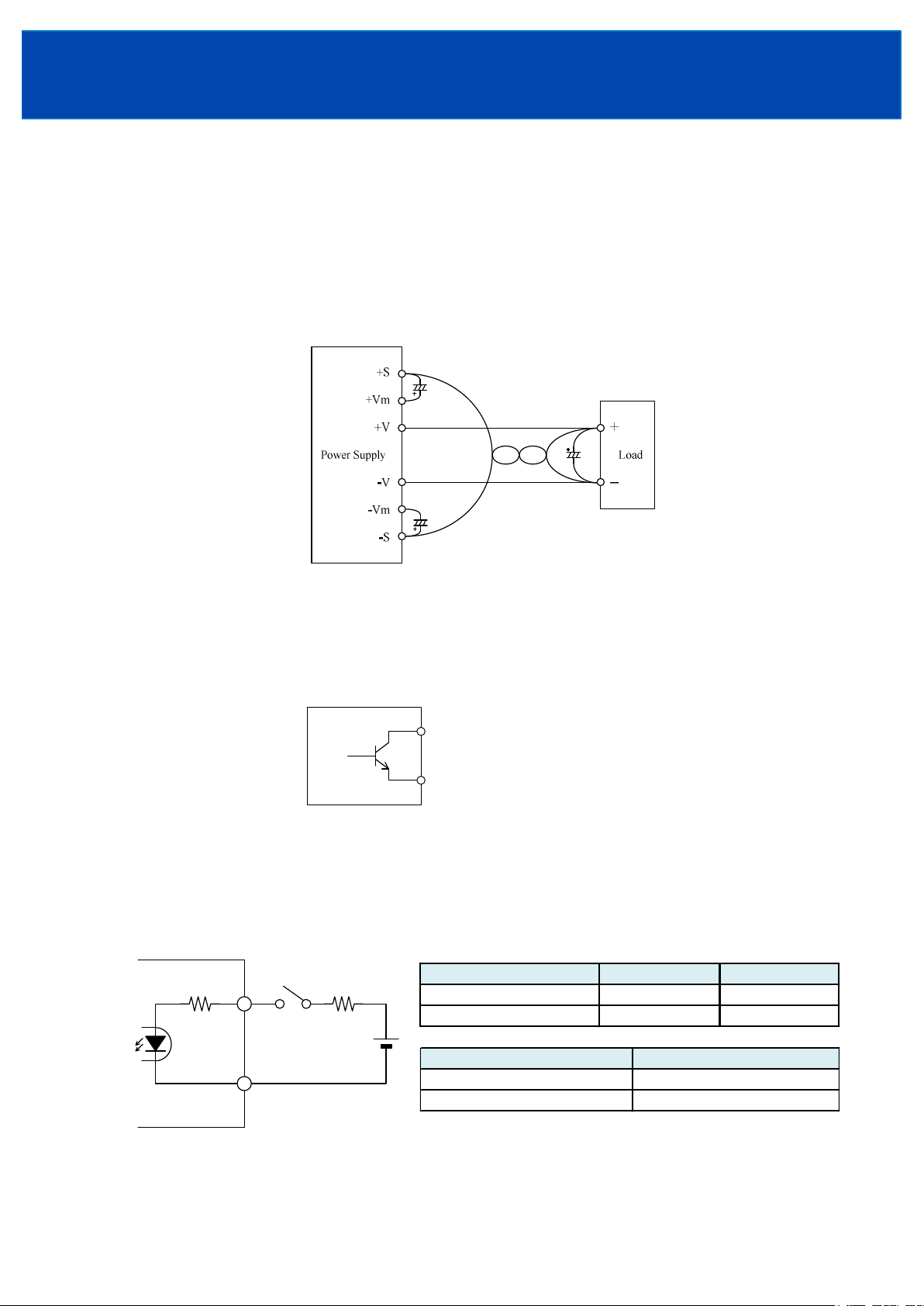
413. Remote Sensing (+S, S terminal)
Remote Sensing function is provided.
This function compensates voltage drop of wiring from output terminals to load terminals. Connect "+S" terminal
to "+" terminal of load and "S" terminal to "" terminal of load with sensing wires.
The total line voltage drop (+ side line and side line) shall be less than 0.3V.
In case that sensing line is too long, it is recommended to connect electrolytic capacitor in the following locations:
1) Across the load terminal,
2) Between "+S" terminal and "+Vm" terminal,
3) Between "S" terminal and "Vm" terminal.
Connect "+S" terminal to "+Vm" terminal, "S" terminal to "Vm" terminal with short pieces when remote
sensing function is not used. If disconnected, OVP function may trigger and voltage will be shut down.
414. Low Output Voltage Detection Signal (PF Signal)
Low output voltage detection signal is provided on option model /FO and /RFO. Power Fail (PF) signal will
turn “High” level to indicate the abnormal status when the output voltage becomes Less than 80% of rated
value caused by either the drop or brownout of the input voltage , OCP, OVP or Delay Shut Down operation.
When the builtin FAN motor of this power supply unit stops, PF signal will turn to “High”. The PF signal is
isolated from input and output by a photocoupler. It uses the open collector method shown in below.
+ PF
PF
Vce max = 50V
Ic max = 5mV
415. Remote ON/OFF Control
Remote ON/OFF control function is provided on option model /R and /RFO.
Using this function allows the user to turn the output on and off without having to turn the AC input off and on.
It is controlled by the external voltage applied to +R and R. This circuit is in the secondary side of the power
supply unit.
Never connect to primary side.
Power
Supply
780
SW
+R
Ω
R
R : External resistans
E : External voltage
R
+R & R terminal condition Fan condition
SW ON (Higher than 4.5V) Op erate
SW OFF (Lower than 0.5V) Not Operate
E
External voltage : E
4.5 ~ 12.5VDC
12.5 ~ 24.5VDC
Output condition
ON
OFF
External resistance : R
No required
1.5kΩ
<Page>
13/19
Page 14

TDKLambda
RWS1000B•1500B Series
INSTRUCTION MANUAL
5. Mounting Method
51. Mounting Method
(1) These models are forced air cooling type power supply. This power supply has ventilating holes. Keep a
space more than 50mm from the front side and back side of the power supply to the peripheral parts.
Also keep a space more than 5mm between other surfaces and the peripheral parts. Never use in the dusty
environment.
Output Terminal
More than 5mm
Front side
Output Terminal
Front side
More than 50mm More than 50mm
Side Fan
More than 5mm
Top
Air flow
Back side
Back side
Fan
Air flow
(2) The maximum allowable penetration of mounting screws is 5mm.
Incomplete thread of mounting screw should not be penetrated.
(3) Recommended torque for mounting screw.
M4 screw : 1.27N·m (13.0kgf·cm)
52. Output Derating according to the Mounting Directions
The standard mounting is direction (A). Direction (B), (C) and (D) are also possible. Please contact us for
other mounting directions.
Never use as mounting direction (E) and (F) shown below.
Refer to the output derating below, load (%) is percent of maximum output current value in a rated output
voltage.
■ Mounting direction
(A) Standard Mounting (C ) (D) (E) Not Possible
INPUT
TERMINAL
(B)
(F) Not Possible
<Page>
14/19
Page 15

■ Output Derating
Standard, /R, /FO, /RFO
120
100
80
TDKLambda
RWS1000B•1500B Series
INSTRUCTION MANUAL
60
Load (%)
40
20
0
20 10 0 10 20 30 40 50 60 70 80
Ta (℃)
/RF
120
100
80
60
Load (%)
40
20
0
20 10 0 10 20 30 40 50 60 70 80
Ta (℃)
Mounting (A)(D)
Ta (°C)
20 +50 100
60 60
Ta (°C)
20 +50 100
60 75
70 50
Load (%)
Mounting (A)(D)
Mounting (A)(D)
Load (%)
Mounting (A)(D)
53. Output Derating according to the Input Voltage
Load (%) is percent of maximum output current value in a rated output voltage.
100
80
Load (%)
60
85
70
90
Input voltage (VAC)
<Page>
15/19
265
Page 16

TDKLambda
Recommended crimp typ e terminal
RWS1000B•1500B Series
INSTRUCTION MANUAL
6. Wiring Method
(1) The output load line and input line shall be separated, and use all lines as thick and short as possible to make
lower impedance. The output load line and input line shall be twisted or use shielded wire to improve noise
sensitivity.
(2) Remote sensing lines and remote ON/OFF control lines shall be twisted and separated from the output lines.
(3) Noise can be eliminated by attaching a capacitor to the load terminals.
(4) The recommended wire type, torque and crimptype terminal :
Model Recommended torque
RWS1000B
RWS1500B
Recommended
Wire
AWG1222
(MAX)
Input terminal M3.5 Screws
1.0N·m (10.2kgf·cm ~ 1.6N·m (16.3kgf·cm)
Output terminal M 5 Screws
2.0N·m (20.4kgf·cm) ~ 2.4N·m (24.4kgf·cm)
Note 1 : When connecting some units, use of two pcs. of 0.8mm thick crimp
type terminal is recommended for input terminal.
Note 2 : For recommended wire type, refer to wire maker recommended
allowable current and voltage drop.
Especially for 12V models, output current is large.
Thick diameter wire is recommended.
Recommended wire type and crimptype terminal vary depending
on use conditions. Choice most appropriate wire type and
crimptype terminal by refering to wire maker recommended
allowable current and voltage drop.
Note 3 : Output terminal is possible to install on arbitrary surface by customer.
(Refer to Fig.1 and Fig.2 for reference.)
Recommended to install single surface at same time to attach terminal cover for safety.
At shipment condition, screw is installed on top side (Fig.1). When installing on front side, please
reverse position of screw and terminal cover (Fig.2).
Do not recommend install dual surface at same time. It may cause touch each screw and cannot attach
terminal cover.
D
8.1mm
t
Mounting pieces
(MAX)
1.0mm 1piece
0.8mm 2pieces
(MAX)
Fig.1 Top side screw (Shipment condition) Fig.2 Front side screw
<Page>
16/19
Page 17

TDKLambda
40
50
50
40
RWS1000B•1500B Series
INSTRUCTION MANUAL
7. The life expectancy
The life expectancy of the power supply is as follows.
The life expectancy is dependent on the lifetime of electrolytic capacitor or the fan.
The life expectancy is not a guaranteed value, please consider as a reference.
Do not use the product which passed over the life expectancy. There is a risk of unexpected output shutdown or
specifications may not be satisfied.
Please contact us for maintenance or exchange the product which passed over the life expectancy.
The life expectancy of power supply is calculated in condition of rated input voltage and 24hour continuous
operation.
Load (%) is percent of maximum output current in a rated output voltage.
Lifetime of electrolytic capacitor
♦ RWS1000B ♦ RWS1500B
Mounting(A),(B),(C),(D) Mounting(A),(B),(C),(D)
Load (%)
100
80
60
5 years
10 years
0
Ta(°C)
2 years
6 years
7 years
Load (%)
100
5 years 2 years
80
5 years
60
10 years
6 years
0
Ta(°C)
Lifetime of fan
The following figure shows the life expectancy of the fan.
The difference between the intake temperature and the exhaust temperature of the power supply at 100%
RWS1000B : 12oC
RWS1500B : 16OC
Measurement point of exhaust temperature
10mm
Measurement
point
100
Power
Supply
Air flow
Fan
<Page>
17/19
10
Life expect ancy (y ears)
1
40 50 60 70
Fan exhaust t emperature(℃)
Page 18

TDKLambda
RWS1000B•1500B Series
INSTRUCTION MANUAL
8. External Fuse Rating
Refer to the following fuse rating when selecting the external input fuse.
Surge current flows when input turn on. Use slowblow fuse or timelug fuse. Fastblow fuse can not be used.
Fuse rating is specified by inrush current value at input turn on.
Do not select the fuse according to actual input current (rms.) values.
RWS1000B : 20A
RWS1500B : 30A
9. Before concluding that the unit is at fault…
Before concluding that the unit is at fault, make the following checks.
(1) Check if the rated input voltage is connected.
(2) Check if the wiring of input and output is correct.
(3) Check if the wire size is not too thin.
(4) Check if the output voltage control (V.ADJ) is properly adjusted.
(5) Check if the Remote ON/OFF control connector is not opened, when use Remote ON/OFF control function
(/R, /RFO).
(6) Check if the output current and output power does not over specifications.
(7) Audible noise can be heard when input voltage waveform is not sinusoidal wave.
(8) Audible noise can be heard during DynamicLoad operation.
(9) Ensure that large capacitor is not connected on the output side.
Please use within maximum capacitance shown below.
Please contact us, if connecting more than the following capacitance value.
Maximum external cap acitance
Model 12V 15V 24V 36V 48V
RWS1000B
RWS1500B
(10) The builtin fan speed is reduced or stop at light load (about 5% or less of rated output current).
The builtin fan is stopped due to output shut down. (Such as OVP or ON/OFF control, etc.)
(11) Check if the Remote sensing terminal is not opened.
100,000uF
<Page>
18/19
Page 19

TDKLambda
RWS1000B•1500B Series
INSTRUCTION MANUAL
10. Warranty Period
Warranty Period applies for Mounting (A) and the number of output ON/OFF is only once a day.
Do not exceed its derating of maximum load.
For damages occurring at normal operation within this warranty period, repair is free of charge.
Please contact our sales office for warranty in other mounting directions if required.
♦ RWS1000B, RWS1500B
Mounting (A)
100
50
Load (%)
Warranted for a period of 5 years
0
Ta(°C)
Following cases are not covered by warranty
(1) Improper usage like dropping products, applying shock and defects from operation exceeding specification
of the unit.
(2) Defects resulting from natural disaster (fire, flood etc.)
(3) Unauthorized modifications or repair.
40 50
Warranted for a period of 2 years
<Page>
19/19
 Loading...