

Page 1

TDK-Lambda
PH-A280 Series
INSTRUCTION MANUAL
PH-A280 Series
Instruction Manual
BEFORE USING THE POWER SUPPLY UNIT
Be sure to read this instruction manual thoroughly before using this product. Pay attention to all cautions and warnings
before using this product. Incorrect usage could lead to an electrical shock, damage to the unit or a fire hazard.
DANGER
· Never use this product in locations where flammable gas or ignitable substances are present.
WARNING
· Do not touch this product or its internal components while circuit is live, or shortly after shut down. There may be high
voltage or high temperature present and you may receive an electric shock or burn.
· When the product is operating, keep your hands and face away from it as you may be injured by flying debris in the event
of a fault.
· Do not make unauthorized changes to this product, otherwise you may receive an electric shock and void your warranty.
· Do not use this product in the event of the emission of smoke or abnormal smell and sound etc. It might lead to fire and/or
electric shock. In such cases, please contact us. Do not attempt repair by yourself, as it is dangerous for the user.
· Do not operate these products in the presence of condensation. It might lead to fire and/or electric shock.
· Do not drop or insert anything into the product. It might lead to a failure, fire and/or electric shock.
CAUTION
· This power supply is designed for use within an end product such that it is accessible to SERVICE ENGINEERS only.
· Confirm connections to input/output terminals and signal terminals are correct as indicated in the instruction manual before
switching on.
· Input voltage, Output current, Output power, Base-plate temperature, ambient temperature and ambient humidity should be
kept within specifications, otherwise the product will be damaged or malfunctioned.
· Do not operate and store this product in an environment where condensation might occur. In such case, waterproof
treatment is necessary.
· Never operate the unit under over current or shorted conditions for 30 seconds or more and out of Input Voltage Range as
specification. Insulation failure, smoking, burning or other damage might occur to the unit.
· Do not use this product in environment with a strong electromagnetic field, corrosive gas or conductive substances.
· For applications which require very high reliability (Nuclear related equipment, traffic control equipment, etc.), it is
necessary to provide a fail safe mechanism in the end equipment.
· The information in this document is subject to change without prior notice. Please refer to the latest version of the data
sheet, etc., for the most up-to date specifications of the product.
· No part of this document may be copied or reproduced in any form without prior written consent of TDK-Lambda.
· Do not inject abnormal voltages into the output or signal of this product. The injection of reverse voltage or over voltage
exceeding nominal output voltage into the output or signal terminals might cause damage to internal components.
· Operation of this product under over-current or short circuit conditions can result in damage. Failures of the product under
these conditions have been assessed and are considered to be safe within the meaning of IEC/UL/CSA 60950-1.
· On the occasion of obtain of Safety Standard, this power supply is not considered for connect between +Vin terminal and
earth.
· In order to maintain SELV output, the base-plate must be protectively earthed in the end application. Where the base-plate
is not earthed, the output must be considered hazardous and must not be made user accessible.
· The output of this product may, under fault conditions, exceed SELV voltage limits. Therefore the output must be earthed
in the end equipment to maintain SELV. If the output is not earthed, they must be considered hazardous and must not be
made user accessible.
· The application circuits and their parameters are for reference only. Be sure to verify effectiveness of these circuits and
their parameters before finalizing the circuit design.
· Use an external fuse to each module to ensure safe operation and compliance with the Safety Standards to which it is
approved. Moreover, it is necessary to use fast-blow type when selecting fuse.
C263-04-11A
Page 2

1
Note : CE MARKING
CE Marking when applied to a product covered by this handbook indicates compliance with the low voltage directive
(2006/95/EC) in that it complies with EN60950-1.
TDK-Lambda
PH-A280 Series
INSTRUCTION MANUAL
C263-04-11A
Page 3
1
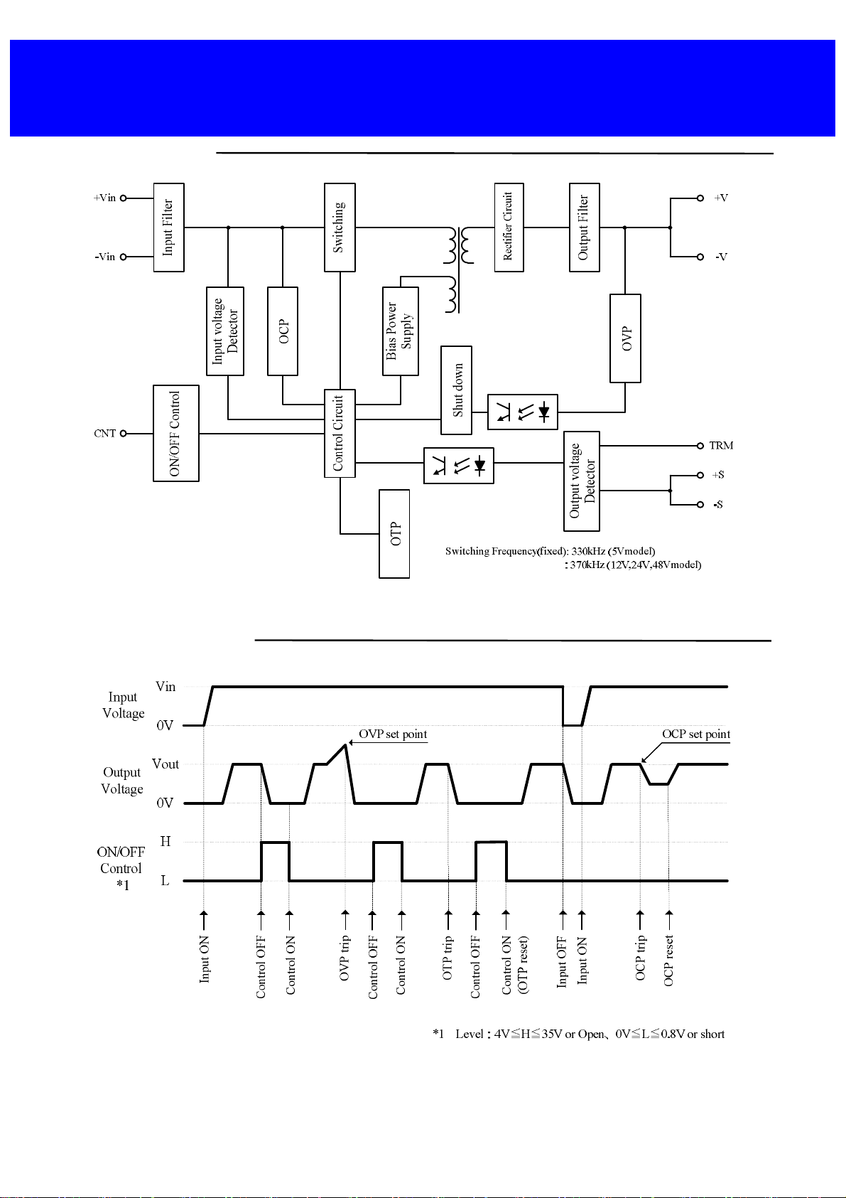
1. Block Diagram
2. Sequence Time Chart
TDK-Lambda
PH-A280 Series
INSTRUCTION MANUAL
1
Page 4
2
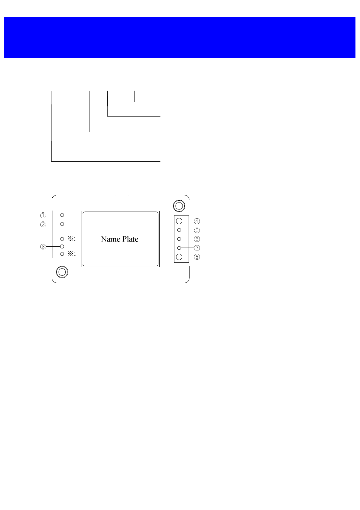
3. Model name identification method
PH 150 A 280 – 12
4. Terminal Explanation
・Base-plate can be connected to FG (Frame Ground) by M3 threaded holes.
・Connect +Vin, -Vin, +V, -V with consideration of contact resistance.
・※1:There is no terminal pin.
Output Voltage
Input Voltage
Series Name
Output Power type
Series Name
① -Vin
② CNT
③ +Vin
④ -V
⑤ -S
⑥ TRM
⑦ +S
⑧ +V
TDK-Lambda
PH-A280 Series
INSTRUCTION MANUAL
: -Input Terminal
: ON/OFF Control Terminal
: +Input Terminal
: -Output Terminal
: -Remote Sensing Terminal
: Output Voltage Trimming Terminal
: +Remote Sensing Terminal
: +Output Terminal
2
Page 5
3
TDK-Lambda
PH-A280 Series
INSTRUCTION MANUAL
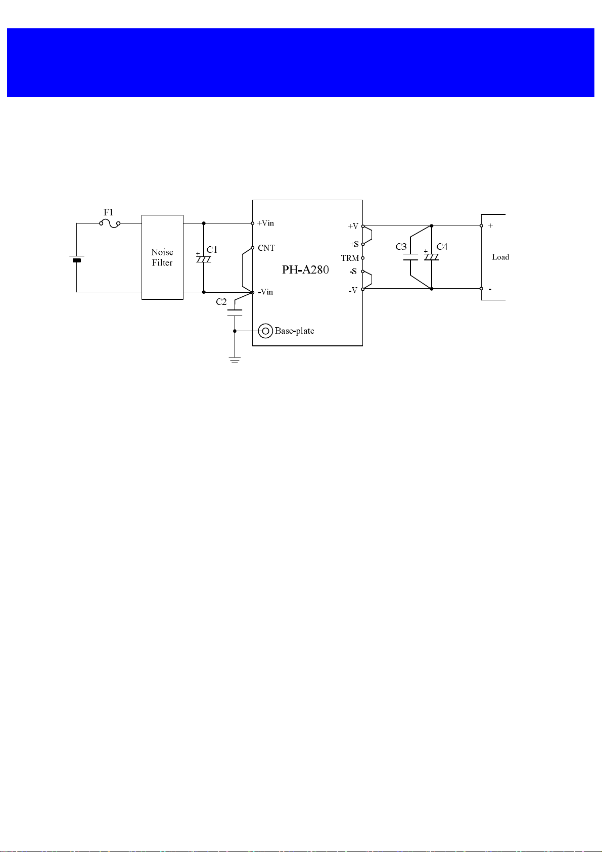
5. Terminal connecting method
In order to use the PH-A280 Series, this module must be connected with external components according
to Fig.5-1.
Pay attention to the each wiring. If it is connected to wrong terminal, the power supply will be damaged.
PH-A280 series employs conduction cooling method. Use heat sink and fan to dissipate heat.
For selection of heat sink and heat sink dissipation method, refer to the Power Module Application Note.
Fig.5-1 Basic connection
3
Page 6

4
F1 : Input Fuse
This PH-A280 Series has no built-in fuse.
Use external fuse to acquire various Safety Standards and to improve safety.
Moreover, use fast-blow type for every power supply.
Furthermore, fuse must be connected to the +Vin side if –Vin side is used as ground, or fuse must be
connected to –Vin side if +Vin side is used as a ground.( However, as mentioned above, the PSU can
consider as Basic insulation only when +Vin and Earth are connected, the safety approval of PSU is not
considered, Please examine together with the system)
Input Fuse Recommended Current Rating :
PH-A280:2A or lower
Consider margin over the actual input voltage to be used when selecting fuse. Moreover, consider I2t fuse
rating for surge current (inrush current) during line throw-in.
C1:
To prevent the effect of input line inductance to the power supply, connect electrolytic capacitor between
+Vin and –Vin terminals.
Take note that in case of large equivalent series resistance (especially operation at low ambient temperature).
Power supply output might not shut down normally.
Recommended Capacitor Value:22μF or more
Moreover, consider to keep margin over the actual input voltage to be used when selecting electrolytic
capacitor.
Note) 1. Use low impedance electrolytic capacitor with excellent temperature characteristics.
(Nichicon CY Series or equivalent)
2. Use more than two recommended capacitor above in parallel when ambient temperature becomes
lower than –20 ºC to reduce ESR.
3. When input line inductance becomes excessively high due to insertion of choke coil, operation of the
power supply could become unstable. For this case, increase C1 value more than the value indicated
above.
4. The module might be damaged by occurrence of surge which is several times the input voltage
due to input line inductance during turn on. Therefore, add electrolytic capacitor at Input
terminal and so on to absorb surge.
Moreover, if slope of input voltage is steep, add electrolytic capacitor so that dv/dt of rise up
slope become less than 20V/μs.
TDK-Lambda
PH-A280 Series
INSTRUCTION MANUAL
4
Page 7

5
TDK-Lambda
PH-A280 Series
INSTRUCTION MANUAL
C2:
For stable operation of the power supply, add ceramic capacitor of 470 pF or more with high voltage rating
between -Vin terminal and baseplate as close as possible to the terminals. However, if the external FG
capacitor between Output terminal and Baseplate is not used, capacitance value should be less than 4200pF.
If external FG capacitor is used, select capacitance taking into consideration clause 6-21. Withstand Voltage
"Withstand Voltage including external components." Moreover, take note that noise might become large or
stable operation might not be attained due to wiring method of printed circuit board, etc. In such case,
countermeasure is possible by increasing C2 capacitance value or adding common mode choke coil before
C1. Addition of common mode choke coil is recommended to improve EMI. When using multiple power
supplies, add choke to each power supply input.
Recommended Withstand Voltage : more than 2.5kVac
C3 :
Add ceramic capacitor as close as possible to the terminals of the power supply in order to reduce output
spike noise voltage. (Recommended : 2.2μF)
Take note that, PCB wiring design might influence output spike noise.
C4:
For stable operation, connect a electrolytic capacitor between +V and –V.
Take note that output ripple could be affected by electrolytic capacitor, equivalent impedance and
inductance characteristics of wiring.
For cases of abrupt changes in load current or input voltage, increasing capacitance value of the external
capacitors could reduce the voltage fluctuation.
Model and C4 recommended values of external output capacitor are below.
Table5-1 C4 : Recommended Values of External Output Capacitor
Note) 1. Use low impedance electrolytic capacitor with excellent temperature characteristics.
(Nippon Chemi-Con LXY Series or equivalent)
2. Use more than three recommended capacitor above in parallel when ambient temperature becomes
lower than –20 ºC to reduce ESR.
3. Take note of the allowable ripple current of the capacitor to be used. Especially, for sudden load
current change, verify actual ripple current and make sure that allowable maximum ripple
current is not be exceeded.
5
Page 8

6
●Reverse Input Connection
Reverse input polarity would cause power supply damage. For cases where reverse connections are
possible, connect a protective diode and fuse. Use protective diode with higher voltage rating than the input
voltage, and with higher surge current rating than the fuse current rating.
TDK-Lambda
PH-A280 Series
INSTRUCTION MANUAL
Fig.5-2 Protection for Reversed Connection of Input
6
Page 9

7
Inp
u
t
Vol
t
a
g
e
TDK-Lambda
PH-A280 Series
INSTRUCTION MANUAL
6. Explanation of Functions and Precautions
6-1. Input Voltage Range
Input voltage range for PH-A280 Series is indicated below.
Input Voltage Range : 200 - 425VDC
Ripple voltage (Vrpl) which results from rectification and filtering of commercial AC line is might be included
within the input voltage as shown in Fig. 6 -1.
In this case, ripple voltage must be limited within the voltage described below.
Allowable Input Ripple Voltage:20Vp-p
When this value is exceeded, the output ripple voltage becomes large.
Take note that sudden input voltage change might be cause variation of output voltage transitionally.
Moreover, maximum value and minimum value of input voltage waveform must not go beyond the limit
of above input voltage range.
InputVotage Range
Fig.6-1 Input Ripple Voltage
6-2. Output Voltage Adjustment Range
Output voltage could be adjusted within the range described below by external resistor or variable resistor.
Output Voltage Adjustment Range
5V : –20% - +20% of Nominal Output Voltage
12V,24V,48V:–20% - +10% of Nominal Output Voltage
When increasing the output voltage, reduce the output current accordingly so as not to exceed the maximum
output power.
Take note that when output voltage is decreased, maximum output current is until rated maximum output
current of specification.
Remote sensing is possible even when output voltage is varied. For details on remote sensing function, please
refer to “6-10. Remote Sensing”.
7
Page 10

8
●Output Voltage Adjustment by External Resistor or Variable Resistor
(1) In case of adjusting output voltage lower
(1-1) Maximum output current
Allowable maximum output current = rated maximum output current of specification.
(1-2) External resister connecting method
Connect an external resistor Radj(down) between the TRM terminal and +S terminal.
TDK-Lambda
PH-A280 Series
INSTRUCTION MANUAL
Fig.6-2 Connection for Output Voltage Trim Down
(1-3) Equation of external resistor and output voltage
Radj(down) : External adjustment resistor
△(%) : Output voltage change rate against nominal output voltage
ex) When setting 12V Model to 10.8V output, Δ(%) should be set at 10%.
R1 : Internal resistor (Please refer to Table 6-1)
Table 6-1 Internal resister value
R2 : Internal resistor (Please refer to Table 6-1)
Below graph is relation Δ(%) and value of external resistor.
10000
1000
5V Model
12V Model
24V Model
48V Model
100
Radj(down)[kΩ]
10
1
0% 5% 10% 15% 20%
Rate of Output Viltage change[%]
Fig.6-3 Δ(%) vs. Radj(down)
8
Page 11

9
(2) In case of adjusting output voltage higher(In case of connect to between TRM and -S)
(2-1) Maximum output current
Allowable maximum output current = maximum output power ÷ adjusting output voltage.
(Becomes less than maximum output current of specification.)
(2-2) External resister connecting method
Connect an external resistor Radj(up) between TRM terminal and -S terminal.
TDK-Lambda
PH-A280 Series
INSTRUCTION MANUAL
Fig.6-4 Connection for Output Voltage Trim Up
(2-3) Equation of external resistor and output voltage
Radj(up) : External adjustment resistor
△(%) : Output voltage change rate against nominal output voltage
ex) When setting 12V Model to 13.2V output, Δ(%) should be set at 10%.
R1 : Internal resistor (Please refer to Table 6-1)
R2 : Internal resistor (Please refer to Table 6-1)
Below graph is relation Δ(%) and value of external resistor.
1000
5V Model
12V Model
24V Model
100
Radj(up)[kΩ]
10
48V Model
1
0% 5% 10% 15% 20%
Rate of Output Viltage change[%]
Fig.6-5 Δ(%) vs. Radj(up)
9
Page 12

10
(3) To adjust output voltage for whole range.
(In case of connect to between TRM and +S and between +V and +S )
(3-1) Maximum output current
In case of adjusting output voltage lower
Allowable maximum output current = rated maximum output current of specification.
In case of adjusting output voltage higher
Allowable maximum output current = maximum output power ÷ adjusting output voltage.
(Becomes less than maximum output current of specification.)
(3-2) External resister connecting method
External resistance (Rex) is connected between TRM terminal and + S terminal, and variable resistor (VR) is
connected between + S terminal and +V terminal.
TDK-Lambda
PH-A280 Series
INSTRUCTION MANUAL
Fig.6-6 Example of Connecting External Resistor
(3-3) External resister and External variable resister
Resistance values of external resistor (Rex) and external variable resistor (VR) is as follows. Moreover, take
note that overvoltage protection (OVP) might activate when resistance value more than recommended
resistance is connected for external variable resistor (VR).
Table 6-2 Values of External Resistor and Variable Resistor
External resistor:±1% Tolerance
10
Page 13

11
TDK-Lambda
PH-A280 Series
INSTRUCTION MANUAL
6-3. Maximum Output Ripple and Noise
Measured value according to the specified methods based on JEITA-9141 (Clause 7.12 and clause 7.13) which
is described in the following .
Connect according to Fig. 6-7 and measure. Connect capacitors (C3 : ceramic capacitor , C4 : electrolytic
capacitor) at 50mm distance from the output terminals.
Measure at ceramic capacitor (C3) terminals as shown in Fig. 6-7 using coaxial cable with JEITA attachment.
Use oscilloscope with 100MHz frequency bandwidth or equivalent.
Fig.6-7 Measurement of Maximum Output Ripple and Noise
Take note that, PCB wiring design might influence output spike noise.
Generally, increasing capacitance value of external capacitor can reduce output ripple voltage and output spike
noise.
6-4. Maximum Line Regulation
Maximum value of output voltage change when input voltage is gradually varied (steady state) within specified
input voltage range.
6-5. Maximum Load Regulation
Maximum value of output voltage change when output current is gradually varied (steady state) within
specified output current range.
When using at dynamic load mode, audible noise could be heard from the power module and output voltage
fluctuation might increase. A thorough pre-evaluation must be performed before using this power supply.
6-6. Base-plate Temperature vs. Output Voltage Drift
Output voltage drift is defined as the rate of voltage change when only base-plate temperature is changed during
operation.
6-7. Over Current Protection (OCP)
This power module has built-in OVP function.
When output current is in overload conditions, output voltage is reduced. Output will recover when short circuit
or overload conditions are released. OCP setting value is fixed and therefore, cannot be externally adjusted.
Take note that power module might be damaged at continuous output short circuit or over load conditions
depending on thermal conditions.
11
Page 14

12
TDK-Lambda
PH-A280 Series
INSTRUCTION MANUAL
6-8. Over Voltage Protection (OVP)
This power module has built-in OVP function.
OVP set point is relative to the rated output voltage value. When output voltage exceed OVP set point, output
voltage shut down. OVP setting value is fixed and therefore, cannot be externally adjusted.
When OVP is triggered, output can be recovered by i) manual reset of the CNT terminal, or ii) by turning input
line off and then turning it on again after the input voltage drops to 0V.
Verifying OVP function shall be done by increasing output voltage with external resistor. For verifying OVP
function, avoid applying external voltage to output terminal because this will cause power supply damage.
6-9. Over Temperature Protection (OTP)
This power module has built-in OTP function. This function operates and shuts down the output when ambient
temperature or internal temperature of power module abnormally rises. OTP operates at 105 ºC to 120 ºC baseplate temperature.
When module shut down due to over temperature, cool down the baseplate sufficiently and recycle output either
by, recycling the input line after dropping down to 0V, or reset by ON/OFF control function.
However, take note that OTP will operate again unless the cause of abnormal heat of the power module is
eliminated.
6-10. Remote Sensing (+S, –S terminal)
Remote sensing terminal is provided to compensate for voltage drop across the wirings from the power supply
output terminal to the load input terminal.
When remote sensing function is not used (local sensing), short +S terminal to +V terminal and,
–S terminal to –V terminal.
When using remote sensing function, output power of power module should be within maximum output power.
Also, use within maximum output adjustable voltage at output terminal.
Moreover, take note that allowable maximum output current which can be used becomes less than the
specification when output terminal voltage is set higher than rated voltage. (Allowable Maximum Output
Current = Maximum Output Power’s specification ÷ Output terminal Voltage)
When wire is long, Power Supply operation might be unstable due to noise. Moreover, please do enough prior
evaluation for remote sensing function by using shielded wire, twist pair, or parallel pattern.
Fig.6-8 Remote Sensing is used Fig.6-9 Remote Sensing is not used
(Local Sensing)
12
Page 15

13
TDK-Lambda
PH-A280 Series
INSTRUCTION MANUAL
6-11. ON/OFF Control (CNT terminal)
Without turning the input supply on and off, the output can be enabled and disabled using this function. This
function also can be used for output sequence of plural power supply.
ON/OFF control circuit is on the primary side (the input side). For secondary control, isolation can be achieved
through the use of a photo-coupler or relay.
Table 6-3 CNT Terminal Level
Note) 1. When ON/OFF control function is not used, CNT terminal should be shorted to –Vin terminal.
2. When using long wiring, for prevention of noise, attach about 0.1uF capacitor between CNT
terminal and –Vin terminal.
3. At L level, source current from CNT terminal to –Vin terminal is 0.2mA–0.3mA.
4. The maximum CNT terminal voltage is 35V.
(1) Output ON/OFF control (2) Secondary (output side) control
Fig.6-10 CNT Connection (1) Fig.6-11 CNT Connection (2)
(3) ON/OFF control when PH-A280 series is connected to PFC circuit.
When PH-A280 series is connected to PFC circuit, the signal that shows normal operation of PFC circuit
connect to CNT terminal of PH-A280 series, and add circuit so that PH-A280 series operates as follows .
When PFC circuit operates normally : Control ON (Output status : ON)
When PFC circuit does not operate : Control OFF (Output status : OFF)
Fig.6-12 CNT Connection (3)
13
Page 16

14
TDK-Lambda
PH-A280 Series
INSTRUCTION MANUAL
6-12. Redundant Operation
Redundant operation is possible for loads that are within the maximum one power supply. When one module is
shut-down by the power failure etc., another one can continue to provide power.
Fig.6-13 Redundant Operation Connection
Note) In redundant operation, the remote sensing cannot be done.
6-13. Parallel Operation
Parallel Operation cannot be used.
6-14. Series Operation
Series operation is possible for PH-A280 series.
Connections shown in Fig. 6-14 and Fig. 6-15 are possible.
Moreover, contact us regarding the maximum allowable number of device connection.
Fig.6-14 Series Operation for High Output Voltage Fig.6-15 ±Output Series Operation
14
Page 17

15
TDK-Lambda
PH-A280 Series
INSTRUCTION MANUAL
6-15. Operating Ambient Temperature
There is no restriction on mounting direction but there should be enough consideration for airflow so that heat
does not accumulate around the power supply vicinity.
Determine external components configuration and mounting direction on PCB such that air could flow through
the heatsink at forced cooling and conduction cooling.
By maintaining actual ambient temperature below 85 ºC and base-plate temperature below 100 ºC, operation is
possible. For details on thermal design, refer to Application Notes “Thermal Design”.
Note) Maximum base-plate temperature is 100 ºC. For worst case operating condition, verify base-plate
temperature at measurement point indicated in Fig. 6-16.
Moreover, ambient air temperature shall be confirmed at a point 10 mm or less from the power
supply side. Use below 85℃ ambient temperature.
Fig.6-16 Measurement Point of Fig.6-17 Derating Curve
Base-plate Temperature
To further improve reliability, it is recommended to use this power supply with ambient temperature and
base-plate temperature derating.
6-16. Operating Ambient Humidity
Take note that condensation could lead to power supply abnormal operation or damage.
6-17. Storage Ambient Temperature
Take note that sudden temperature changes can cause condensation buildup, and other harmful affects to each
terminal solder.
6-18. Storage Ambient Humidity
Take enough care when storing the power module because rust which causes poor solderability would form in
each terminal when stored in high temperature, high humidity environment.
6-19. Cooling Method
Operating temperature range is specified by the base-plate temperature. Therefore, several methods of heat
dissipation are possible
For details on thermal design, refer to Application Notes “Thermal Design”.
15
Page 18

16
TDK-Lambda
PH-A280 Series
INSTRUCTION MANUAL
6-20. Withstand Voltage
This power module is designed to have a withstand voltage of 3kVAC between input and output, 2.5kVAC between
input and base-plate and 500VAC between output and base-plate for 1 minute. When conducting withstand voltage
test during incoming inspection, set the current limit value of the withstand voltage testing equipment to 20mA.
Furthermore, avoid throw in or shut off of the testing equipment when applying or when shutting down the test
voltage. Instead, gradually increase or decrease the applied voltage. Take note especially not to use the timer of
the test equipment because when the timer switches the applied voltage off, impulse voltage which has several
times the magnitude of the applied voltage is generated causing damage to the power supply.
Connect the terminals as shown in the diagram below.
3kVAC 1 minute 2.5kVAC 1 minute
Fig.6-18 Withstand Voltage Test for Input – Output Fig.6-19 Withstand Voltage Test for Input –
Base-plate
500VAC 1 minute
Fig.6-20 Withstand Voltage Test for Output – Base-plate
16
Page 19

17
Withstand Voltage Testing with External Application
The above Withstand Voltage Testing specification applies only to power supply as stand–alone unit. Please take
note of the following points when Withstand Voltage Testing is performed with attached external application.
For applications that require capacitor connections between input to FG and output to FG as shown in the
Fig. 6-21, if the total capacitance value of C2, C5 is 4,200pF or more, must be set capacitor to between output
and FG according to the below formula in order to satisfy 3kVAC Withstand Voltage test between Input
terminal and Output terminal.
If the formula below is not satisfied, power supply might be damaged.
Formula for calculating total capacitance between Output terminal and FG terminal
(C6+C7) > 5×(C2+C5)-21250 [pF]
TDK-Lambda
PH-A280 Series
INSTRUCTION MANUAL
6-21. Isolation Resistance
Use DC isolation tester (MAX 500V) between output and base-plate. Isolation resistance value is 100MΩ and
above at 500VDC applied voltage. Make sure that during testing, the isolation testers do not generate a high pulse
when the applied voltage is varied.
Ensure that the tester is fully discharged after the test.
6-22. Vibration
Vibration of power supply is defined when mounted on printed circuit board.
For details, refer to “7. Mounting Method”.
6-23. Shock
Withstand shock value is defined to be the value at TDK -Lambda shipment and packaging conditions, or when
mounted on printed circuit board.
When mounting on printed circuit board, refer to “7. Mounting Method”.
Fig.6-21 Example of connecting external application
Over 100MΩ at 500VDC
Fig.6-22 Isolation Resistance Test
17
Page 20

18
7. Mounting Method
7-1. Mounting Method
By the following instruction shown in Fig. 7-1, mount power supply onto printed circuit board.
3 Screw
Spring Washer
Plain Washer
Heatsink
Silicone Grease
3Threaded
Mounting Hole
Power supply
Printed Circuit Board
TDK-Lambda
PH-A280 Series
INSTRUCTION MANUAL
Plain Washer
Spring Washer
3 Screw
Fig.7-1 Mounting Method
(1) Method to Fixing on Printed Circuit Board
To fix a power module onto printed circuit board, use M3 screws and mount it to the M3 threaded holes of the
power module. Recommended torque is 0.54N∙m.
(2) Mounting Holes
Mounting holes of the power supply are connected to base-plate. Connect base-plate to FG (Frame Ground) by
using this mounting holes.
(3) Mounting Holes on Printed Circuit Board
Refer to the following sizes when determining diameter of hole and land diameter of printed circuit board.
Input / Signal terminals (φ1.0 mm )
Hole diameter : φ1.5 mm
Land diameter : φ2.5 mm
Output terminals (φ1.5 mm )
Hole diameter : φ2.0 mm
Land diameter : φ3.5 mm
Mounting Holes (FG)
Hole diameter : φ3.5 mm
Land diameter : φ7.0 mm
For position of the holes, see outline drawing of the power supply.
18
Page 21

19
TDK-Lambda
PH-A280 Series
INSTRUCTION MANUAL
(4) Recommended Material of PCB
Recommended materials of the printed circuit board is double sided glass epoxy with through holes.
(thickness t:1.6mm , copper 35μm)
(5) Input / Output Pattern Width
Large current flows through input and output pattern. If pattern width is too narrow, heat on pattern will increase
because of voltage drop of pattern. Relationship between allowable current and pattern width varies depending
on materials of printed circuit board, thickness of conductor. It is definitely necessary to confirm on
manufacturers of printed circuit board for designing pattern.
(6) Method of Connecting Terminals
Connect +Vin, -Vin, +V, -V with consideration of contact resistance .
7-2. Heatsink Installation Method
(1) Method of Fixing Heatsink
To fix the heatsink onto power module, use M3 screws and mount it to the M3 threaded holes (2 places) at
the base-plate side. Recommended torque is 0.54 N∙m.
Use silicone grease or thermal conductive sheet in between heatsink and base-plate to minimize the contact
thermal resistance and to enhance the heat conductivity.
Also use the no-warped heatsink and make sure good contact between base-plate and heatsink.
(2) Mounting Hole of Heatsink
Recommended mounting hole is as follows.
φ3.5 Non-threaded hole
7-3. Regarding Vibration
The vibration specification of the power supply is determined assuming that only the power supply is mounted
on printed circuit board. To prevent excessive force to the power supply and the printed circuit board, fix the
heatsink to the chassis as well as to the power supply when a large size of heatsink is used.
7-4. Recommended Soldering Condition
Recommended soldering conditions are as follows.
(1) Soldering dip
Dip condition : 260ºC within 10 seconds
Pre-heat condition : 110ºC for 30 - 40 seconds
(2) Soldering iron
350ºC within 3 seconds
Note) Soldering time changes according to heat capacity of soldering iron, pattern on printed circuit board,
etc. Please confirm actual performance.
7-5. Recommended Cleaning Condition
Recommended cleaning condition after soldering is as follows.
(1) Cleaning solvent
IPA (isopropyl alcohol )
(2) Cleaning Procedure
Use brush and dry the solvent completely.
19
Page 22

20
TDK-Lambda
PH-A280 Series
INSTRUCTION MANUAL
8. Before Concluding Power Module Damage
Verify following items before concluding power supply damage.
(1) No output voltage
・Is specified input voltage applied?
・Are the ON/OFF control terminal (CNT), remote sensing terminal (+S, –S), output voltage trimming
terminal (TRM) correctly connected?
・For cases where output voltage adjustment is used, is the resistor or variable resistor setting, connections
correctly done?
・Are there no abnormalities in the output load used?
・Is the base-plate temperature within the specified temperature range?
・Is the room temperature within the specified temperature range?
(2) Output voltage is high
・Are the remote sensing terminals (+S, –S) correctly connected?
・Is the measurement done at the sensing points?
・For cases where output voltage adjustment is used, is the resistor or variable resister setting, connections
correctly done?
・Are there no abnormalities in the output load used?
(3) Output voltage is low
・Is specified input voltage applied?
・Are the remote sensing terminals (+S, –S) correctly connected?
・Is the measurement done at the sensing points?
・For cases where output voltage adjustment is used, is the resistor or variable resistor setting, connections
correctly done?
・Are there no abnormalities in the output load used?
(4) Load regulation and line regulation is large
・Is specified input voltage applied?
・Are the input terminals and the output terminals firmly connected?
・Is the measurement done at the sensing points?
・Is the input or output wire too thin?
(5) Output ripple voltage is large
・Is the measurement done according to methods described in the Instruction Manual or is it an equivalent
method?
・Is the input ripple voltage value within the specified value?
9. Warranty Period
Warranty period is 5 years.
For damages occurring at normal operation within this warranty period, repair is free of charge.
Following cases are not covered by warranty
(1) Improper usage like dropping products, applying shock and defects from operation exceeding
specification of the unit.
(2) Defects resulting from natural disaster (fire, flood etc.)
(3) Unauthorized modifications or repair by the buyers’ defects not cause by our company.
20
Page 23

21
10. Option Heatsink
TDK-Lambda
PH-A280 Series
INSTRUCTION MANUAL
*1: at convection cooling
10-1.For PH-A280
(1) HAQ-10T (Convection cooling)
Thermal resistance: 7.5℃/W
(Forced air cooling)
3
3
.
5
Heatsink and ambient [℃/W]
Thermal resistance between
Average air velocity [m/s]
21
 Loading...