

Page 1
TDK-Lambda
PFE300SA
2
2
C274-01-01A
SPECIFICATIONS
MODEL
ITEMS
1 Nominal Output Voltage V 12 28 48
2 Maximum Output Current A 25 10.8 6.3
3 Nominal Output Power W 300 302.4 302.4
4 Efficiency (Typ.) (*1) % 84 / 85 87/ 89 88 / 90
5 Input Voltage Range (*2)(*5)(*9) - 85 - 265 VAC
6 Input Frequency (*2) Hz 47 - 63
7 Input Current (*1) A 3.8 / 1.9 3.7 / 1.8 3.6 / 1.8
8 Power Factor (*1)(*5) - 0.95 min
9 Output Voltage Accuracy (*1) % +/-2
10 Output Voltage Range % -20 / +20
11 Maximum Ripple & Noise (*5) mV 120 280 480
12 Maximum Line Regulation mV 48 56 96
13 Maximum Load Regulation mV 48 56 96
14 Over Current Protection - 105% - 140% (Automatic recovery method)
15 Over Voltage Protection - 125% - 145% (Inverter shutdown method)
16 In-rush Current (Typ.) (*1)(*5)(*6) A 20A / 40A peak
17 Parallel Operation - -
18 Series Operation (*7) - Possible
19 Operating Temperature (*3)(*8) -
20 Operating Humidity - 20 - 95%RH (No Dewdrop)
21 Storage Temperature - -40°C - +100°C
22 Storage Humidity - 10 - 95%RH (No Dewdrop)
23 Cooling (*4) - Conduction Cooled
24 Temperature Coefficient - Less than 0.02% / °C
25 Withstand Voltage - Input-Baseplate : 2.5kVAC, Input-Output : 3.0kVAC for 1min.
26 Isolation Resistance - Output to Baseplate 500VDC more than 100MW (25°C,70%RH)
27 Vibration - At No Operating, 10-55Hz (Sweep for 1min.)
28 Shock - 196.1m/s
29 Safety - Approved by UL60950-1,CSA60950-1,EN60950-1
30 Weight (Typ.) g 200
31 Size (W x H x D) mm 61 x 12.7 x 116.8 (Refer to Outline Drawing)
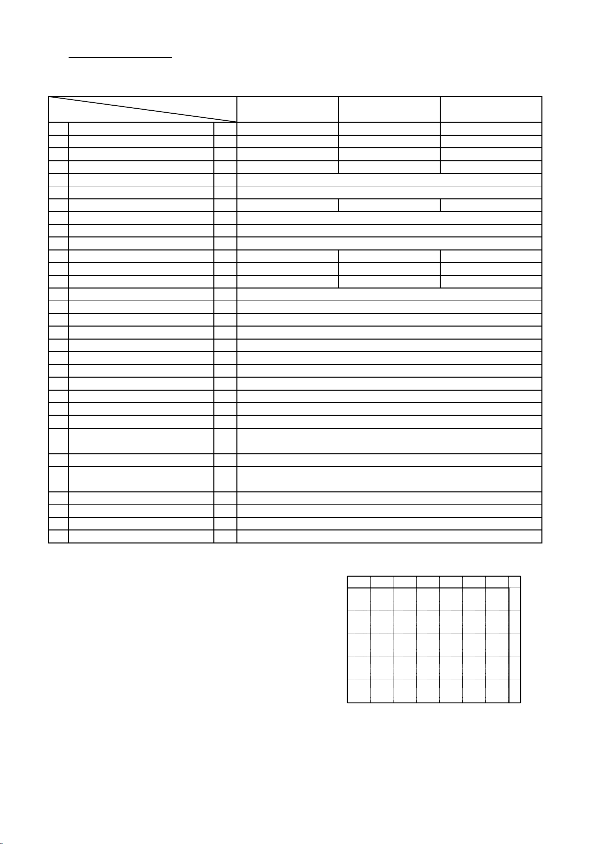
*Read instruction manual carefully, before using the power supply unit. Derating Curve
PFE300SA-12 PFE300SA-28 PFE300SA-48
-40°C - +100°C
Output-Baseplate : 1.5kVDC for 1min.
Amplitude 0.825mm Constant (Maximum 49.0m/s
) X,Y,Z 1 hour each
=NOTES=
*1. At 100VAC/200VAC and maximum output power.
(Baseplate Temperature = +25°C.)
*2. For cases where conformance to various safety specs
(UL, CSA, EN) are required, input voltage range
will be 100 - 240VAC(50 - 60Hz).
*3. Ratings - refer to Derating Curve on the right.
*4. Heatsink has to be chosen according to Instruction manual.
*5. External components are needed for operation.
(Refer to basic connection and instruction manual.)
*6. First inrush current. Not applicable for the inrush current to
Noise Filter for less than 0.2ms.
*7. Refer to Instruction manual.
*8. Ambient Temperature min=-40°C.
*9. Start-up at Vin=83VAC guaranteed.
100
80
60
Load (%)
40
20
0
-40 -20 0 20 40 60 80 100
Baseplate Temperature (℃)
Page 2
TDK-Lambda
PFE300SA
W
C274-01-02
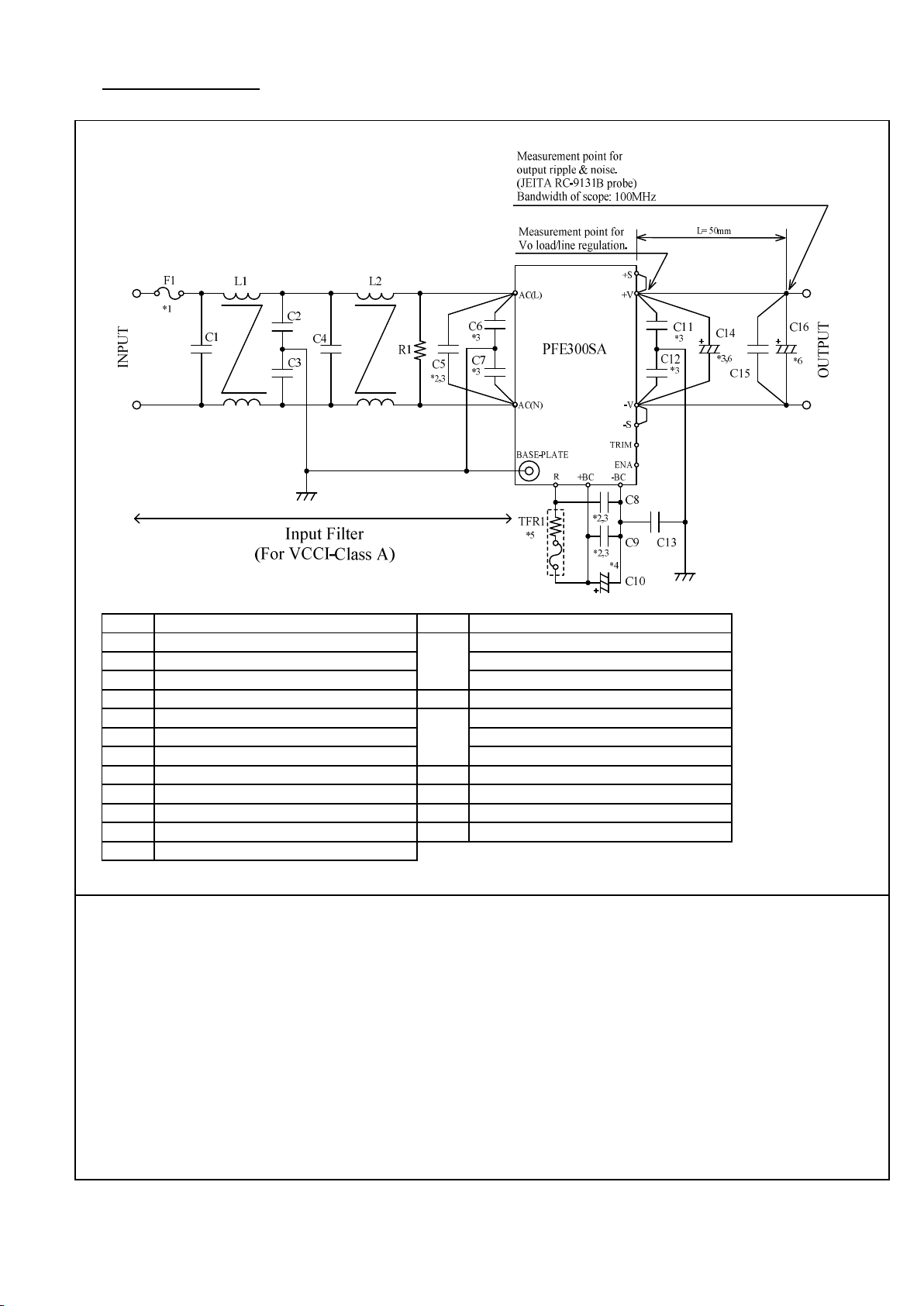
BASIC CONNECTION
F1 AC250V 15A C13 1000pF
C1 AC250V 1uF (Film) 12V: 25V 1000uF (Elec.)
C2 4700pF C14 28V: 50V 470uF (Elec.)
C3 4700pF 48V: 100V 220uF (Elec.)
C4 AC250V 1uF (Film) C15 100V 2.2uF (Ceramic)
C5 AC250V 1uF (Film) 12V: 25V 1000uF (Elec.)
C6 1000pF C16 28V: 50V 470uF (Elec.)
C7 1000pF 48V: 100V 220uF (Elec.)
C8 450V 1uF (Film) R1 0.5W 470k
C9 450V 1uF (Film) TFR1 10W 139°C (Res., Thermal fuse)
C10 450V 470uF L1 6mH
C11 0.033uF L2 6mH
C12 0.033uF
==NOTES==
*1. Use an external fuse of fast blow type for each unit.
*2. The allowable ripple current of capacitor must be more than 3A(rms).
*3. Put this capacitor near the terminal as close as possible.
*4. The maximum capacitance that can be used is less than 1200uF(Rated capacitance).
Avoid the connection of capacitance which is more than above, else it will lead to
module to damage.
*5. The inrush current at AC throw in can be suppressed by the external Resistor
(Built-in thermal fuse) connected between the R and +BC terminals.
*6. If the ambient temperature is less than -20°C, use twice the recommended capacitor above.
*7. Refer to instruction manual for further details.
 Loading...