

Page 1

TDK-Lambda
LS 200 Series
INSTRUCTION MANUAL
LS200 Series
Instruction Manual
BEFORE USING THE POWER SUPPLY UNIT
Pay attention to all warnings and cautions before using the unit. Incorrect usage may lead to an electrical
shock, damage to the unit or a fire hazard.
WARNING and CAUTION
z Do not modify.
z Do not touch the internal components; it may have high voltage or high temperature. You may get electrical
shock or burn.
z When the unit is operating, keep your hands and face away from it as you may be injured by flying debris in
the event of a fault.
z This power supply is designed for use within an end product. Stick the WARNING label for users on the
system equipment and notify in the system instruction manual.
z Never operate the unit under over current or short-circuit conditions for more than 30 seconds or outside its
specified Input Voltage Range, which could result in damage but there is no possibility of fire or burning.
z Confirm connections to input/output terminals are correct as indicated in the instruction manual.
z Hazardous voltage may appear at output terminals depending on the type of failure. The outputs of these
products must be earthed in the end equipment to maintain SELV.
If the outputs are not earthed, they must be considered hazardous and must not be made user accessible.
Note: CE MARKING
CE marking, when applied to the LS series products, indicates compliance with the Low Voltage Directive
(2006/95/EC) in that it complies with EN60950-1
2nd edition.
DWG NO. : PA607-04-01
APPD CHK DWG
Page 2

TDK-Lambda
LS 200 Series
INSTRUCTION MANUAL
1. Terminal Explanation
Please pay extra attention to the wiring. Incorrect connection may cause damage the power supply.
z When connecting input and output wiring, input AC-Line should be OFF.
z Input wiring and output wiring shall be separated, otherwise noise susceptibility of power supply unit
will be weak.
z The protective earth (PE) must be connected to the instrument chassis and the chassis of this power
supply unit.
z Remote sensing lines shall be twisted or use shielded wire.
z Remote ON/OFF control lines shall be twisted or use shielded wire.
1-1. Front Panel Explanation
(1) L : Input terminal Live line (Fuse in line)
(2) N : Input terminal Neutral line
(3)
(4) - V : - Output terminal
(5) +V : + Output terminal
(6) Output voltage adjustable trimmer
(7) Output monitoring indicator (Green LED : ON)
(8) CN2: Remote sensing and ON/OFF control signal
: Functional Ground
FG
1
Page 3

246
8
5
3
1
TDK-Lambda
LS 200 Series
INSTRUCTION MANUAL
2. Terminal Connecting Method
2-1. Terminal connecting method
z Input must be off when making connection.
z Connect FG terminal to ground terminal of the equipment.
z The output load line and input line shall be separated and twisted to improve noise immunity.
Maximum output current of each output terminal is 20A. If more than 20A, use 2 terminals.
2-2. CN2 Connector pin configuration and Function
Pin
CN2
PCB
Configuration Function
No.
1 +Vm Connected to +Output terminal of the power supply
unit. (+Vm terminal cannot supply load current)
2 +S Remote sensing terminal for +Output
(For remote sensing function, this compensates for line
drop between power supply terminals and load terminals. Connect to +Vm terminal when remote sensing
function is not required)
3 -Vm Connected to -Output terminal of the power supply
unit. (-Vm terminal cannot supply load current)
4 -S Remote sensing terminal for -Output
(For remote sensing function, this compensates for line
drop between power supply terminals and load terminals. Connect to -Vm terminal when remote sensing
function is not required)
5 NC No connection
6 NC No connection
7 CNT+ Remote ON/OFF control terminal
(When CNT+ is pulled to TTL low, power supply unit
turns ON. Otherwise, it turns OFF)
8 CNT- Return loop for CNT+ signal
2
Page 4

7
812
TDK-Lambda
LS 200 Series
INSTRUCTION MANUAL
2.3. Basic connection (Local sensing)
(1) Connect “+S” terminal to “+Vm” terminal with sensing wire
(2) Connect “-S” terminal to “-Vm” terminal with sensing wire
(3) Connect “CNT+” terminal to “CNT-” terminal with wire
• Please use attached CN2 connector for each connection.
2-4. Remote sensing required
(1) Connect “+S” terminal to “+Vm” terminal of load with sensing wire.
(2) Connect “-S” terminal to “-Vm” terminal of load with sensing wire.
(3) Connect “CNT+” terminal to “CNT-” terminal with wire.
• The accuracy of output voltage will be affected when sensing terminal is opened.
3
Page 5

TDK-Lambda
LS 200 Series
INSTRUCTION MANUAL
3. Explanation of Functions and Precautions
3-1. Input Voltage Range
Input voltage range is single phase 85 ~ 264VAC (47 ~ 63Hz) or 120 ~ 373VDC.
Input voltage which is out of specification, may damage the unit. For cases where conformance to various safety specifications (UL, CSA, EN) are required, input voltage range shall be 100~240VAC
(50/60Hz).
Note: LS200 series is able to withstand Input Surge of 300VAC for 5 seconds.
3-2. Output Voltage Range
V.ADJ trimmer is for output voltage adjustment within the range of specifications. Turning the trimmer
clockwise will increase the output voltage. Kindly note that Over Voltage Protection (OVP) function
may trigger if the output voltage is increased excessively. Please ensure that the output power is below
the rated output power, and output current is below the maximum output current (3.3V ~ 15V and 48V)
or below the peak output current (24V ~ 36V) when output voltage is raised.
3-3. Inrush Current
Power Thermistor is built in to protect the circuit from high Inrush Current. Please select suitable input
switch and fuse rating in case of re-input the power at high temperature.
3-4. Over Voltage Protection (OVP)
The OVP function will shutdown the output. The input shall be removed for a few minutes, and then reinput for recovery of the output. OVP setting is fixed and cannot be adjusted externally.
3-5. Over Current Protection (OCP)
OCP function activates when the output current exceeds the specified OCP limit. The output will automatically recover when the overload condition is removed. Do not operate overload or dead short conditions for more than 30 seconds, which could result in damage. There is no possibi lity of fire or burning.
3-6. Over Temperature Protection (OTP)
Over Temperature Protection function (manual reset type) is available. When ambient or internal temperature rises abnormally, OTP function will shut down the outpu t. To recover the unit, first shut down
the AC input and let the unit cool down before turning ON the AC input.
3-7. Remote Sensing (+S, -S terminal)
Remote sensing function is provided to compensate for voltage drop across the wiring from the power
supply output terminals to the load input terminals. Connect “+S” terminal to “+Vm” terminal of the
load and “-S” terminal to the “-Vm” terminal of the load with sensing wires. The total line voltage
drop (+Vm side line and –Vm side line) shall be less than 0.3V. In the case that sensing wires are too
long, it is necessary to put an electrolytic capacitor across the load terminals. Example of external capacitor is listed in the table below :
Minimum external capacitance at the load input terminal
MODEL 3.3V 5V 7.5V 12V 15V 24V 36V 48V
LS200 2,200uF 1,000u 470uF
4
Page 6

TDK-Lambda
LS 200 Series
INSTRUCTION MANUAL
When not using the remote sensing function, +S & -S terminal shall be connected to +Vm & –Vm
terminals of CN2 respectively. Please use the attached connector of CN2 for this purpose.
This is to ensure stability and accuracy of the output.
3-8. Remote ON/OFF Control
F
Remote ON/OFF control is available.
Output can be remotely switched OFF by connecting an external logic high signal to CNT+ terminal
versus CNT- terminal. And when the external signal is changed to logic low, the output will switched
ON immediately.
CNT+ Level versus CNT- terminal Output
0 ~ 0.8V ON
3 ~ 12V OFF
When not using the remote ON/OFF function, CNT+ terminal must be shorted to CNT- terminal with
the attached connector shown in 2-3.
5
Page 7

TDK-Lambda
LS 200 Series
INSTRUCTION MANUAL
3-9. Output Ripple & Noise
Ripple & noise are measured at 20MHz using a 300mm twisted pair of load wires terminated with a
0.1uF film capacitor & 47uF electrolytic capacitor. When load lines are longer, ripple becomes larger.
The output ripple cannot be measured accurately if the probe ground lead of oscilloscope is too long.
At low temperature, large ripple & noise may also be observed due to large ESR of the internal Electrolytic Capacitors especially at -25
o
C. Output voltage rise may not be smooth during initial turn on at low
temperature.
3-10. Series Operation
For series operation, either method (A) or (B) is possible.
Method ( A ) Method ( B )
Power Supply
+S
+Vm
Power Supply
+S
+Vm
-Vm
-S
+S
+Vm
-Vm
-S
Note: In case of Method (A), please connect diodes to prevent the reverse voltage.
3-11. Parallel Operation
(A) (B)
Power Supply
+S
+Vm
-Vm
-S
+S
+Vm
-Vm
-S
Load
Load
Power Supply
+S
+Vm
-Vm
-S
+S
+Vm
-Vm
-S
-Vm
-S
+S
+Vm
-Vm
-S
Load
Load
Load
(A) Operation to increase the Output Current is not possible.
(B) Operation as a Backup Power Supply is possible as follows.
(1) Set the power supply output voltage higher by the amount of forward voltage drop (V
the diode.
(2) Please adjust the output voltage of each power supply to be the same.
(3) Please use within the specifications for output voltage and output current.
Connect “CNT+” terminal to “CNT-” terminal with wire CN2 connector.
6
) of
F
Page 8

TDK-Lambda
LS 200 Series
INSTRUCTION MANUAL
3-12. Output Peak Power
Operating conditions for peak power/current models:
(a) Reduce peak current according to output derating curve for higher ambient temperature
(see section 5.1)
(b)
exceeded rated value specified. Power supply may shut down and operate in hiccup or
constant current limiting mode.
Duty: not more than 35%
τ
Duty = ---- x 100 (%)
T
Output might shut down when the rated current or the continuous peak output time (τ)
Input voltage : 115 ~ 230 VAC +/- 20% (50/60 Hz)
Continuous peak out time (τ) :
Peak output current (Ip) : Within the rated peak output current
< 10s
τ
2
x ---- < Irms max
Ip
T
Applicable model for Peak Output Power :
Model Irms max.
LS200-24 6.15 A
LS200-36 4.10 A
7
Page 9

TDK-Lambda
LS 200 Series
INSTRUCTION MANUAL
4. Isolation / Withstand Voltage
4-1. Isolation Test
Isolation resistance between output and FG (chassis) shall be more than 100MΩ at 500VDC. For safety,
voltage setting of DC isolation tester must be done before the test. Ensure that the unit is fully discharged
after the test.
Output ~ FG (chassis): 500VDC, 100MΩ or more
4-2. Withstand Voltage
This series is designed to withstand 3.0kVAC between input and output, 1.5kVAC between input and FG
(chassis) and 500VAC between output and FG (chassis) each for 1 minute. When testing withstands voltage, set current limit of withstand voltage test equipment at 20mA (Output-FG (chassis): 100mA). The
applied voltage must be gradually increased from zero to testing value and then gradually decreased for
shut down. When timer is used, the power supply may be damaged by high impulse voltage at timer
switch on and off. Connect input and output as follows :
(a) Input ~ FG (chassis) : solid line (c) Output ~ FG (chassis) : 500VAC
1.5kVAC, 1min (20mA) 1min (100mA)
(b) Input ~ Output : dotted line
3kVAC, 1min ( 20mA )
5. Mounting Directions
5-1. Output Derating according to the Mounting Directions
(a) Forced air convection, with FAN & cover (Exhale)
8
Page 10

TDK-Lambda
LS 200 Series
INSTRUCTION MANUAL
Recommended standard mounting is Method (A).
Method (B) and (C) are also possible.
Refer to the Output Derating below.
Please do not use installation Method (D), (E) and (F).
Free air convection, without Fan & Cover
(b)
Recommended standard mounting is Method (A).
Method (B), (C), (E) and (F) are also possible.
9
Page 11

TDK-Lambda
LS 200 Series
INSTRUCTION MANUAL
Refer to the Output Derating below.
Please do not use installation Method (D).
10
Page 12

TDK-Lambda
LS 200 Series
INSTRUCTION MANUAL
5-2. Output Derating according to the ambient temperature
(A) LS200 series Output Derating versus Ambient Temperature.
The cooling system is forced air (exhale).
In the following derating curve, the maximum output current please refers to PA607-01-01.
LS200 – 3.3V, 5V, 7.5V, 12V, 15V, 24V, 36V & 48V
(B) LS200/L series Output Derating versus Ambient Temperature.
The cooling system is convection cool or forced air (exhale) with airflow > 3m/s.
In the following derating curve, the Y-axis for maximum output current please refers to PA607-01- 01/L.
i. LS200/L – 3.3V, 5V & 7.5V
11
Page 13

TDK-Lambda
LS 200 Series
INSTRUCTION MANUAL
ii. LS200/L – 12V, 15V, 24V, 36V & 48V
(C) LS200/L series for Output Derating versus Input Voltage.
The cooling system is convection cool or forced air (exhale) with airflow > 3m/s.
In the following derating curve, the Y-axis for maximum output current please refers to PA607-01-01/L.
LS200/L – 3.3V, 5V, 7.5V, 12V, 15V, 24V, 36V & 48V
12
Page 14
p
TDK-Lambda
LS 200 Series
INSTRUCTION MANUAL
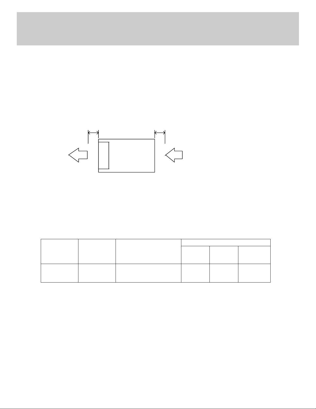
5-3. Mounting Method
1) This power supply unit is a forced air-cooling system with a built-in fan.
2) This power supply has ventilation holes in front and the back.
In consideration of the heat radiation and safety, please keep a distance of more than 100mm from front side
and more than 50mm from rear side.
3) Please note that ventilation will be worsened in a dusty environment.
4) Built in fan is limited life part, which requires periodic replacement. (Replacement will be charged).
5) The ambient temperature of this power supply is less than 50mm from the center of the front side.
6) Maximum allowable penetration of mounting screws into the power-supply is 5mm.
7) Recommended torque for mounting screws (M4): 1.27 N⋅m (13.0 kgf⋅cm).
Air flow
Ba ck Si d e
More than 50mm
Fan
To
More tha n 100mm
Fr ont Side
6. Wiring Method
z The input and output load wires shall be separated and twisted to improve noise immunity.
z Both wires must be as thick and short as possible to have lower impedance.
z Noise can be reduced by connecting a film capacitor with 0.1uF capacitance across the load terminals.
z For safety and EMI considerations, connect the FG terminal of LS200 series to mounting set ground
terminal.
z The recommended wire type :
MODEL
LS200
Note 1 : When using separate loads, it is recommended to use 2 pieces of 0.8mm thick crimp-type terminal.
Note 2 : For recommended wire diameter, refer to wire maker recommended allowable current and voltage
Recommended
Wire
AWG14-22
drop. For higher output current model like 3.3V & 5V, bigger diameter wire is recommended.
Recommended torque
M3.5 Screws
1.0 N⋅m (9.8 kgf⋅cm) ~
1.4 N⋅m (13.7 kgf⋅cm)
Recommended crimp-type terminal
D
(MAX) t (MAX)
6.8mm
0.8mm
Mounting
Pieces
(MAX)
2 pieces
7. External Fuse Rating
Refer to the following fuse rating when selecting the external input fuse. Surge current flows when input is
turned on. Fuse rating is specified by Inrush Current value at input turns on. Do not select the fuse according to
input current (rms) values under the actual load condition.
LS200 : F5A , 250V
13
Page 15

m
TDK-Lambda
LS 200 Series
INSTRUCTION MANUAL
8. Fan Life Expectancy.
The fan life has limitation. Following figure shows the life expectancy of fan against temperature.
Measurement point of fan exhaust temperature
Air Flow
P.S.
FRONT SIDE
50
Temperature
measurement point
9. Before concluding that the unit is at fault…
Please make the following checks.
(1) Check if the rated input voltage is connected and within specification.
(2) Check if the wiring of input and output is correct.
(3) Check if the I/O terminal connection is properly tighten by required torque.
(4) Check if the wire thickness is enough.
(5) Check if the output voltage trimmer (V.ADJ) is properly adjusted. OVP might be triggered and output is
shutdown.
(6) Check if the built-in fan is operating. Is fan stopped or blocked by something?
(7) Power supply has ventilating holes in front and the back. Check if there is any blockage or dust, etc.
(8) Is the chassis of power supply abnormally hot? The output is shutdown by OTP operation.
Please disconnect or turn off the AC input and let the unit cool down sufficiently before turning ON the AC
input again.
(9) Check if the output current and output wattage does not exceed the specification.
(10) Audible noise may be heard when input voltage waveform is not sinusoidal.
(11) Audible noise may be heard during dynamic load operation.
(12) Ensure that a large capacitor is not connected across the output terminals. Please use within maximum ca-
pacitance shown below.
Maximum external capacitance
MODEL 3.3V 5V 7.5V 12V 15V 24V 36V 48V
LS200 10,000uF 5,000uF 1,000uF
14
Page 16

TDK-Lambda
LS 200 Series
INSTRUCTION MANUAL
10. Warranty Condition
This product is under warranty for 3 years (based on 8 hours/day operation) from the date of shipment. During the
warranty period, TDK-Lambda will, at its option, either repair or replace products prove to be defective.
Warranty applies but not limited to the following.
(1)
(2)
(3)
Following cases are not covered by warranty.
(1)
(2)
(3)
Average operating temperature (ambient temperature of the power supply unit) is under 40oC.
Average load factor is 80% or less.
Installation method: Standard installation.
Improper usage and mis-handling like dropping or applying shock to the unit and defects from operation
exceeding specification of the product.
Defects resulting from natural disaster (fire, flood).
Unauthorized modification or repair.
15
 Loading...