

Page 1

TDK-Lambda
LS 25-150 Series
INSTRUCTION MANUAL
LS25~150 Series
Instruction Manual
BEFORE USING THE POWER SUPPLY UNIT
Pay attention to all warnings and cautions before using the unit. Incorrect usage could lead to an electrical
shock, damage to the unit or a fire hazard.
WARNING and CAUTION
z Do not modify.
z Do not touch the internal components, they may have high voltage or high temperature. You may get
electrical shock or burned.
z When the unit is operating, keep your hands and face away from it as you may be injured by flying debris in
the event of a fault.
z This power supply is designed for use within an end product. Stick the WARNING label for users on the
system equipment and notify in the system instruction manual.
z Never operate the unit under over current or short-circuit conditions for more than 30 seconds or outside its
specified Input Voltage Range, which could result in damage. There is no possibility of fire or burning.
z Confirm connections to input/output terminals are correct as indicated in the instruction manual.
z This power supply has a possibility for hazardous voltage to appear at output terminal depending on the type
of failure. The outputs of these products must be earthed in the end equipment to maintain SELV.
If the outputs are not earthed, they must be considered hazardous and must not be made user accessible.
Note: CE MARKING
CE marking, when applied to the LS series products, indicates compliance with the Low Voltage Directive
(2006/95/EC) in that it complies with EN60950-1
.
DWG NO. : PA582-04-01-C
APPD CHK DWG
Page 2
TDK-Lambda
LS 25-150 Series
INSTRUCTION MANUAL
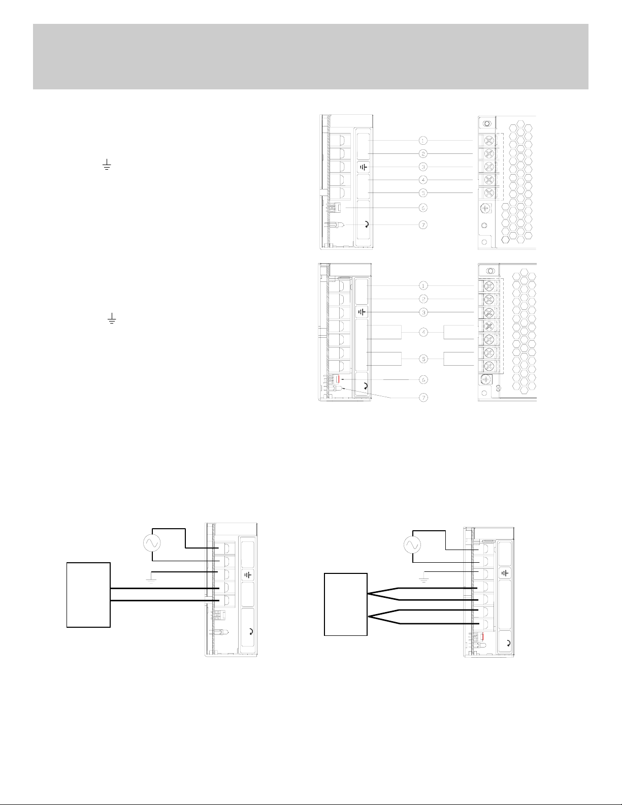
1. Terminal Explanation
LS25, LS35, LS50, LS75
(1) L : Input terminal Live line (Fuse in line)
(2) N : Input terminal Neutral line
(3) FG
: Functional Ground
(4) - V : - Output terminal
(5) +V : + Output terminal
(6) Output voltage adjustable trimmer
(7) Output monitoring indicator (Green LED : ON)
LN V
-V +V
ADJ
H
LS100, LS150
(1) L : Input terminal Live line(Fuse in line)
(2) N : Input terminal Neutral line
(3) FG
: Functional Ground
(4) -V : - Output terminal
( 25A max./ terminal)
(5) +V : + Output terminal
( 25A max./ terminal)
(6) Output voltage adjustable trimmer
(7) Output monitoring indicator (Green LED : ON)
LN V
-V
-V +V
+V
ADJ
H
2. Terminal connecting method
1
2
3
4
5
1
2
3
4
5
6
7
z Input must be off when making connection.
z Connect FG terminal to ground terminal of the equipment.
z The output load line and input line shall be separated and twisted to improve noise immunity.
LS25, LS35, LS50, LS75 LS100, LS150
LN V
-V
-V +V
+V
ADJ
H
LOAD
+
LN V
-V +V
-
LOAD
ADJ
H
+
Maximum output current of each output terminal is 25A except for LS25 (15A).
If more than 25A, use 2 terminals.
1
Page 3

TDK-Lambda
LS 25-150 Series
INSTRUCTION MANUAL
3. Explanation of Functions and Precautions
3-1. Input Voltage Range
Input voltage range is single phase 88 ~ 264VAC (47 ~ 63Hz) or 125 ~ 373VDC for LS25 ~ LS100.
For LS150, selectable switch 115/230VAC will decide the input voltage range as mentioned in the table below.
Input voltage which is out of specification, may damage the unit. For cases where conformance to various
safety specs(UL,CSA,EN) are required, input voltage range will be 100~240VAC (50/60Hz ).
Note : LS series able to withstand Input Surge of 300VAC for 5 seconds.
LS150 – Selectable voltage range
Selected Range Applicable Input Voltage Range in VAC Applicable Input Voltage Range in VDC
115 88 ~ 132 NA
230 176 ~ 264 248 ~ 373
3-2. Output Voltage Range
V.ADJ trimmer is for output voltage adjustment within the range of specifications. Turning the trimmer clockwise will
increase the output voltage. Note over voltage protection ( OVP ) function may trigger if the output voltage is increased
excessively.
3-3. Inrush Current
Power Thermistor is built in to protect the circuit from high Inrush Current. Please select suitable input switch and fuse
rating in case of re-input the power at high temperature.
3-4. Over Voltage Protection (OVP)
The OVP function will shutdown the output except for LS25. The input need to be removed for a few minutes, and then
re-input for recovery of the output. OVP setting is fixed and cannot be adjusted externally.
Note : For LS25, OVP function will cause the output into ”hiccup” mode and damage the unit.
3-5. Over Current Protection (OCP)
OCP function operates when the output current exceeds OCP specifications. The output will automatically recover when
the overload condition is removed. Do not operate overload or dead short conditions for more than 30 seconds, which
could result in damage. There is no possibility of fire or burning.
3-6. Output Ripple & Noise
Ripple & noise are measured at 20MHz by using a 300mm twisted pair of load wires terminated with a 0.1uF film capacitor & 47uF electrolytic capacitor. When load lines are longer, ripple becomes larger. The output ripple cannot be
measured accurately if the probe ground lead of oscilloscope is too long. At low temperature, large ripple & noise may
also be observed due to large ESR of the internal Electrolytic Capacitors especially at -25degC. Output voltage rise may
not be smooth during initial turn on at low temperature.
2
Page 4
d
TDK-Lambda
LS 25-150 Series
INSTRUCTION MANUAL
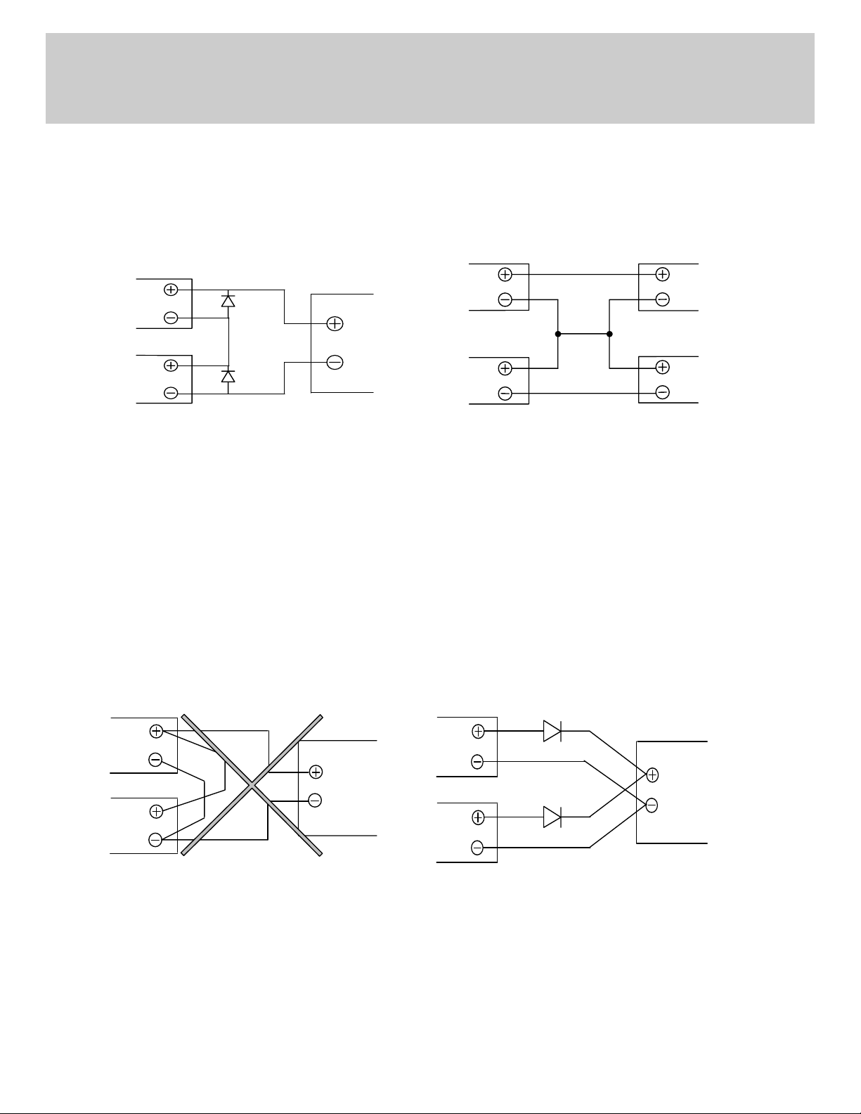
3-7. Series Operation
For series operation, either method ( A ) or ( B ) is possible.
Method ( A ) Method ( B )
Power
Supply
Output
Terminal
Load
Power
Supply
Output
Terminal
Load
Output
Terminal
Output
Terminal
Note : In case of Method ( A ), please connect diodes to prevent the reverse voltage.
3-8. Parallel Operation
(A) Operation to increase the Output Current is not possible.
(B) Operation as a Backup Power Supply is possible as follows.
1. Set the power supply output voltage higher by the amount of forward voltage drop ( V
2. Please adjust the output voltage of each power supply to be the same.
3. Please use within the specifications for output voltage and output current.
(A) (B)
Power
Supply
Output
Terminal
Power
Supply
Out pu t
Ter minal
) of the diode.
F
Load
Output
Terminal
Load
Out pu t
Ter minal
Loa
3
Page 5

TDK-Lambda
LS 25-150 Series
INSTRUCTION MANUAL
4. Isolation / Withstand Voltage
4-1. Isolation Test
Isolation resistance between output and FG (chassis) shall be more than 100MΩ at 500VDC. For safety, voltage setting
of DC isolation tester must be done before the test. Ensure that the unit is fully discharged after the test.
(a) Output ~ FG (chassis) : 500VDC, 100MΩ or more
AC(L)
AC(N)
Isolation
Tester
FG
+ V
+V
- V
- V
4-2. Withstand Voltage
This series is designed to withstand 3.0kVAC between input and output, 1.5kVAC between input and FG (chassis) and
500VAC between output and FG (chassis) each for 1 minute. When testing withstand voltage, set current limit of withstand voltage test equipment at 20mA ( Output-FG (chassis) : 100mA ). The applied voltage must be gradually increased
from zero to testing value and then gradually decreased for shut down. When timer is used, the power supply may be
damaged by high impulse voltage at timer switch on and off. Connect input and output as follows :
(a) Input ~ FG (chassis) : solid line (c) Output ~ FG (chassis) : 500VAC, 1min (100mA)
1.5kVAC, 1min (20mA)
(b) Input ~ Output : dotted line
3kVAC, 1min ( 20mA )
Withstand
Voltage
Tester
AC(L)
AC(N)
FG
+V
+V
-V
-V
Withstand
Voltage
Tester
AC(L)
AC(N)
FG
+V
+V
-V
-V
4
Page 6

TDK-Lambda
LS 25-150 Series
INSTRUCTION MANUAL
5. Mounting Directions
5-1. Output Derating according to the Mounting Directions
Recommended standard mounting is Method ( A ). Method ( B ), ( C ) and ( D ) are also possible. Refer to the Output
Derating below. Please do not use installation Method ( E ), where the PCB will be on the topside and heat will be
trapped inside the unit.
In the following derating curve, the maximum output current is denoted as 100%.
`
(A) Output Derating versus Ambient Temperature (Convection Cooling)
LS25-3.3
Load (%)
120
100
80
60
50
40
20
0
-25 0 25 50 75 100
Output Derating Vs Ambient Temperature
40 65 70
o
Ambient Temperature (
C)
Mounting
A & D
Mounting
B & C
5
Page 7

TDK-Lambda
LS 25-150 Series
INSTRUCTION MANUAL
LS25-5, -12, -15, -24, -36 & -48
Load (%)
120
100
80
60
50
40
20
0
-25 0 25 50 75 100
Output Derating Vs Ambient Temperature
40 65 70
Ambient Temperature (
o
C)
LS35-3.3, -5, -12, -15, -24, -36 & -48
Mounting
A & D
Mounting
B & C
Load (%)
120
100
80
60
50
40
20
0
-25 0 25 50 75 100
Output Derating Vs Ambient Temperature
45
Ambient Temperature (
65 70
o
C)
Mounting
A,B & D
Mounting
C
6
Page 8

TDK-Lambda
LS 25-150 Series
INSTRUCTION MANUAL
LS50-3.3, -5, -12, -15, -24, -36 & -48
Load (%)
120
100
80
70
60
50
40
20
0
-25 0 25 50 75
LS75-3.3, -5
Output Derating Vs Ambient Temperature
40 60
Ambient Temperature (°C)
70
100
Mounting
A, B & D
Mounting
C
Load (%)
120
100
80
60
40
20
70
0
-25 0 25 50 75
Output Derating Vs Ambient Temperature
45
Ambient Temperature (°C)
60
70
100
Mounting
A, B & D
Mounting
C
7
Page 9

TDK-Lambda
LS 25-150 Series
INSTRUCTION MANUAL
LS75-12, -15, -24, -36 & -48
Load (%)
120
100
80
70
60
40
20
0
-25 0 25 50 75
Output Derating Vs Ambient Temperature
70 60
Ambient Temperature (°C)
Mounting
A, B & D
Mounting
C
100
LS100-3.3, -5
Load (%)
120
100
80
60
40
20
50
0
-25 0 25 50 75
Output Derating Vs Ambient Temperature
45
40
Ambient Temperature (°C)
70
100
Mounting
A & B
Mounting
C & D
8
Page 10

TDK-Lambda
LS 25-150 Series
INSTRUCTION MANUAL
LS100-12, -15, -24, -36 & -48
Load (%)
120
100
80
60
50
40
20
0
-25 0 25 50 75
Output Derating Vs Ambient Temperature
45
Ambient Temperature (°C)
70
100
Mounting
A & B
Mounting
C & D
LS150-3.3, -5
Load (%)
120
Output Derating Vs Ambient Temperature
100
80
60
50
40
20
0
-25 0 25 50 75
Ambient Temperature (°C)
40
9
Mounting
A
Mounting
B, C & D
70 30
100
Page 11

TDK-Lambda
LS 25-150 Series
INSTRUCTION MANUAL
LS150-12, -15, -24, -36 & -48
Load (%)
120
100
80
70
60
40
20
0
-25 0 25 50 75
Output Derating Vs Ambient Temperature
40
Ambient Temperature (°C)
70
100
Mounting
A
Mounting
B, C & D
(B) Output Derating versus Input Voltage (Convection Cooling)
LS100-3.3, -5, -12, -15, -24, -36 & -48
LOAD (%)
120
100
80
60
40
20
0
88 230
Output Derating Vs Input Voltage
115
Vin (VAC)
NOTE : LS25, LS35, LS50, LS75 & LS150 series do not require Input Voltage Derating.
10
264
Page 12

TDK-Lambda
LS 25-150 Series
INSTRUCTION MANUAL
5-2 Mounting Method
1) This is convection cooling type power supply. In consideration of the heat radiation and safety, please keep a dis-
tance of more than 15mm between the power supply and the peripheral parts. When lining up multiple units, please
make sure to place them 15mm or more apart from each other.
2) Maximum allowable penetration of mounting screws into the power-supply is 5mm except LS25 (4mm).
3) Recommended torque for mounting screws of LS25 ~ LS150 (M3 screw) : 0.49 N⋅m (5.0 kgf⋅cm).
6. Wiring Method
z The input and output load wires shall be separated and twisted to improve noise immunity.
z Both wires must be as thick and short as possible to make lower impedance.
z Noise can be reduced by connecting a film capacitor with 0.1uF capacitance across the load terminals.
z For safety and EMI considerations, connect the FG terminal of LS series to mounting set ground terminal.
z The recommended wire type :
MODEL
LS25 AWG16-22
LS35 ~ LS150
Recommended
Wire
AWG14-22
Recommended torque
M3.0 Screws
0.49 N⋅m (5.0 kgf⋅cm)
M3.5 Screws
1.0 N⋅m (9.8 kgf⋅cm) ~
1.4 N⋅m (13.7 kgf⋅cm)
Recommended crimp-type terminal
D
(MAX) t (MAX)
6.0mm
6.8mm
0.8mm
0.8mm
Mounting
Pieces
(MAX)
2 pieces
2 pieces
Note 1 : When using separate loads, it is recommended to use 2 pieces of 0.8mm thick crimp-type terminal.
Note 2 : For recommended wire diameter, refer to wire maker recommended allowable current and voltage
drop. For higher output current model like 3.3V & 5V, bigger diameter wire is recommended.
11
Page 13

TDK-Lambda
LS 25-150 Series
INSTRUCTION MANUAL
7. External Fuse Rating
Refer to the following fuse rating when selecting the external input fuse. Surge current flows when input turns on.
Fuse rating is specified by Inrush Current value at input turn on. Do not select the fuse according to input current (rms)
values under the actual load condition.
LS25 : F1.6A , 250V
LS35, LS50 : T2A , 250V
LS75 : T2.5A , 250V
LS100 : F4A , 250V
LS150 : F5A , 250V
8. Before concluding that the unit is at fault, make the following checks.
z Check if the rated input voltage is connected.
z Check if the wiring of input and output is correct.
z Check if the wire size is correct.
z Check if the output voltage trimmer (V.ADJ) is properly adjusted.
z Check if the output current and output wattage does not exceed the specification.
z Ensure that a large capacitor is not connected across the output terminals. Please use within maximum capacitance
shown below.
Maximum external capacitance
MODEL 3.3V 5V 12V 15V 24V 36V 48V
LS25 10,000uF 5,000uF 2,000uF 1,000uF 500uF
LS35~LS50 10,000uF 5,000uF 2,000uF 500uF
LS75~LS150 10,000uF 5,000uF 1,000uF
NOTE : It is normal to hear audible noise from power-supply under Dynamic Load operation or if the input voltage
waveform is not sinusoidal.
9. Warranty Condition
This product is under warranty for 3 years (based on 8 hours/day operation) from the date of shipment. During the
warranty period, TDK-Lambda will, at it’s option, either repair or replace products prove to be defective.
Warranty applies but not limited to the following.
(1) Average operating temperature (ambient temperature of the power supply unit) is under 40
(2) Average load factor is 80% or less.
(3) Installation method : Standard installation.
Following cases are not covered by warranty.
(1) Improper usage and mis-handling like dropping or applying shock to the unit and defects from operation
exceeding specification of the product.
(2) Defects resulting from natural disaster (fire, flood).
(3) Unauthorized modification or repair.
o
C.
12
 Loading...