

Page 1

TDKLambda
GXE600 Series
INSTRUCTION MANUAL
GXE600 Series
Instruction Manual
BEFORE USING THE POWER SUPPLY UNIT
Be sure to read this instruction manual thoroughly before using this product. Pay attention to all cautions and
warnings before using this product. Incorrect usage could lead to an electrical shock, damage to the unit or a fire
hazard.
DANGER
Never use this product in locations where flammable gas or ignitable substances are present.
INSTALLATION WARNING
• When installing, ensure that work is done in accordance with the instruction manual. When installation is
improper, there is risk of electric shock and fire.
• Installation shall be done by Service personnel with necessary and appropriate technical training and
experience. There is a risk of electric shock and fire.
• Do not cover the product with cloth or paper etc. Do not place anything flammable around. This might cause
damage, electric shock or fire.
WARNING on USE
• Do not touch this product or its internal components while circuit in operation, or shortly after shutdown. You
might receive a burn.
• While this product is operating, keep your hands and face away from it as you may be injured by an
unexpected situation.
• For products with no cover, do not touch them as there are highvoltage and high temperature parts inside.
Touching them might cause injury such as electric shock or burn.
• There are cases where high voltage charge remains inside the product. Therefore, do not touch even if they are
not in operation as you might get injured due to high voltage and high temperature.
You might also get electric shock or burn.
• Do not make unauthorized changes to this product nor remove the cover as you might get an electric shock or
might damage the product. We will not be held responsible after the product has been modified, changed or
disassembled.
• Do not use this product under unusual condition such as emission of smoke or abnormal smell and sound etc.
Please stop using it immediately and shut off the product.
It might lead to fire and electric shock. In such cases, please contact us. Do not attempt repair by yourself, as it
is dangerous for the user.
• Do not operate and store these products in environments where condensation occurs due to moisture and
humidity. It might lead fire and electric shock.
• Do not drop or apply shock to this product. It might cause failure. Do not operate these products mechanical
stress is applied.
CAUTION on MOUNTING
• Confirm connections to input/output terminals are correct as indicated in the instruction manual before
switching on.
• Input/output line, please use the wires as short and thick as possible.
• Do not use this product in special environment with strong electromagnetic field, corrosive gas or conductive
substances and direct sunlight, or places where product is exposed to water or rain.
• Mount this product properly in accordance with the instruction manual, mounting direction and shall be
properly be ventilated.
• Please shut down the input when connecting input and output of the product.
• When installing in environment where conductive foreign, dust and liquid might be present,
please consider penetration of above foreign material in the power supply by installing filter, to prevent trouble
or malfunction.
<Page>
1/28 A2630401A
Page 2

TDKLambda
GXE600 Series
INSTRUCTION MANUAL
CAUTION on USE
• Product individual notes are shown in the instruction manual. If there is any difference with common notes
individual notes shall have priority.
• Before using this product, be sure to read the catalog and instruction manual. There is risk of electric shock or
damage to the product or fire due to improper use.
• Input voltage, Output current, Output power, ambient temperature and ambient humidity should be kept within
specifications, otherwise the product will be damaged, or cause electric shock or fire.
• If the builtin fuse is blown, do not use the product even after replacing the fuse as there is risk of abnormality
inside. Be sure to request repair to our company.
• For products without builtin protection circuit (element, fuse, etc.), insert fuse at the input to prevent smoke,
fire during abnormal operation.
As for products with builtin protection circuit, depending on usage conditions, builtin protection circuit might
not work. It is recommended to provide separate proper protection circuit.
• For externally mounted fuse do not use other fuses aside from our specified and recommended fuse.
• This product was made for general purpose electronic equipment use and is not designed for applications
requiring high safety (such as extremely high reliability and safety requirements). Even though high reliability
and safety are not required, this product should not be used directly for applications that have serious risk for
life and physical safety. Take sufficient consideration in failsafe design (such as providing protective circuit
or protective device inside the system, providing redundant circuit to ensure no instability when single device
failure occurs).
• When used in environments with strong electromagnetic field, there is possibility of product damage due to
malfunction.
• When used in environment with corrosive gas (hydrogen sulfide, sulfur dioxide, etc.) , there is possibility that
they might penetrate the product and lead to failure.
• When used in environments where there is conductive foreign matter or dust, there is possibility of product
failure or malfunction.
• Provide countermeasure for prevention of lightning surge voltage as there is risk of damage due to abnormal
voltage.
• Connect together the frame ground terminal of the product and the ground terminal of the equipment for safety
and noise reduction. If these grounds are not connected together, there is risk of electric shock.
• Parts with lifetime specifications (builtin electrolytic capacitor) are required to be replaced periodically.
Set the overhaul period depending on the environment of usage and perform maintenance.
Also, note that there are cases when EOL products cannot be overhauled.
• Take care not to apply external abnormal voltage to the output. Especially, applying reverse voltage or
overvoltage more than the rated voltage to the output might cause failure, electric shock or fire.
• This product has possibility that hazardous voltage might occur in output terminal depending on failure mode.
The output of these products must be protected in the end use equipment to maintain SELV.
• The output of these product is considered to be a hazardous energy level (The voltage is 2V or more and the power
is 240VA or more). It must not be made accessible to users.
• Protection must be provided for Service Engineers against indirect contact with the output terminals and/or to
prevent tools being dropped across them.
• While working on this product, the AC input power must be switched off and the input and output voltage
should be zero.
<Page>
2/28
Page 3

TDKLambda
GXE600 Series
INSTRUCTION MANUAL
Special Instructions for IEC/EN/ES/CSA 606011
• These products are designed for continuous operation within an overall enclosure, and must be mounted such
that access to the mains terminals is restricted.
• These products are not suitable for use in the presence of flammable anesthetics mixtures with air or with
oxygen, or with nitrous oxide.
• The output circuit has not evaluated for connecting to Applied Parts. For end products intended to connect the
output circuit to Applied Parts, suitable evaluation of the separation, leakage current, dielectric voltage
withstand, and related requirements should be conducted.
• Doublepole/ neutral fusing. Option model “/SF” have fuse only live line.
• These products provide One Means Of Patient Protection (1MOPP) between Primary/Secondary and FG, and
Two Means Of Patient Protection (2MOPP) between Primary and Secondary.
• The 48V model have possibility that hazardous voltage might occur in output terminal depending on failure
mode (The output voltage is 60V or more on failure mode). The output of these products must be protected in the
end use equipment. If it is not acceptable, contact us.
• These products are classed as ordinary equipment according to IEC/EN/ES/CSA606011 and are NOT
protected against the ingress of water.
• Reference should be made to local regulations concerning the disposal of these products at the of their
useful life.
Note
• Take note that traces of sheet metal processing be left in our power supplies.
• When disposing product, follow disposal laws of each municipality.
• Published EMI (CE, RE) or immunity is the result when measured in our standard measurement conditions and
might not satisfy specification when mounted and wired inside enduser equipment.
Use the product after sufficiently evaluating at actual enduser equipment.
• When exporting our products, apply for necessary permissions as required by rules and regulations of Foreign
Exchange and Foreign Trade Control Act.
• Catalogue, contents of the instruction manual might be changed without a prior notice. Refer to latest
catalogue or instruction manual.
• Reproduction or reprinting the instruction manual or its portion is forbidden without our permission.
• CE Marking
CE Marking, when applied to a product covered by this handbook, indicates compliance with the low voltage
directive.
STORAGE METHOD AND STORAGE PERIOD
• Store in original package
• Prevent excessive vibration, impact and external force from being applied during storage.
• Store in an area out of direct sunlight
• Temperature and humidity should be within range of product specification (with no condensation)
• Storage period should be up to two years from receiving.
<Page>
3/28
Page 4

1. Model name identification method
GXE 600 24 /□
TDKLambda
GXE600 Series
INSTRUCTION MANUAL
2. Terminal Explanation
Option (*1)
Rated Output Voltage
Output Power type
Series Name
+V +V V V
(*1) Blank : Standard
/A : With cover type.
L N
Standard
1
N : Input terminal Neutral line (Fuse in line) (M3.5 screw)
2
L : Input terminal Live line (Fuse in line) (M3.5 screw)
3
4
5
6
7
8
: Earth terminal (M3.5 screw)
V : Output terminal (M4 screw)
+V : + Output terminal (M4 screw)
Output voltage adjustment trimmer
Output monitoring indicator (Green LED)
CN84 : Signal connector CN84
<Page>
4/28
Page 5

CN84 Connector pin Configuration and Functions
No. Configuration Function
1 +Vm
2 +S
3 NC Do not connect.
4 NC Do not connect.
5 Vm
6 S
7 PC Current balance terminal. (For current balancing in parallel operation.)
8 CC Output current external control terminal.
9 PV Output voltage external control terminal.
10 COM Ground for PC, CC and PV signal, internally connected to S.
11 PF
12 AC Fail
13 CNT 1 Remote ON/OFF control terminal (1).
14 +STB External standby sup p ly (5V/1A).
15 CNT 2 Remote ON/OFF control terminal (2).
16 STB Ground for External standby supp ly, internally connected to TOG terminal.
17 SG Ground for DAT A, internally connected to T OG terminal.
18 TOG Ground for CNT, PF and AC Fail signal.
19 +DATA +DATA signal terminal for RS485. (Noninverted differential pair.)
20 DATA DATA signal terminal for RS485. (Inverted differential pair.)
Output monitor terminal, internally connected to +output terminal.
( +Vm terminal cannot supp ly load current.)
Remote sensing terminal for +output.
(For remote sensing function, which compensates for line drop between
power sup ply terminals and load terminals. Connect to +Vm terminal when
remote sensing function unnecessary.)
Ground for output monitor terminal, internally connected to outp ut terminal.
( Vm terminal cannot supply load current.)
Remote sensing terminal for output side.
(For remote sensing function, which compensates for line drop between
power supply terminals and load terminals. Connect to Vm terminal when
remote sensing function unnecessary.)
Power Fail signal outp ut terminal.
(Open collector outp ut. As the output voltage or current drop and shutdown,
PF signal will be "High".)
AC Fail signal outp ut terminal.
(Open collector outp ut. As the input voltage drops to less than 85Vac, AC
Fail signal will be "High".)
TDKLambda
GXE600 Series
INSTRUCTION MANUAL
* CN84・・・Connector(JST)
Connector
S20BPHDSS
Housing Terminal Pin
PHDR20VS
SPHD002TP0.5 (AWG24 ~ 28) or
SPHD001TP0.5 (AWG22 ~ 26)
Hand Crimping Tool : YRS620 (SPHD002TP0.5) (JST) or YC610R (SPHD001TP0.5) (JST)
Use maker recommended crimping tool.
These are connected by short pieces at time of shipment.
"+Vm" terminal (Pin No.1) to "+S" terminal (Pin No.2)
"Vm" terminal (Pin No.5) to "S" terminal (Pin No.6)
<Page>
5/28
Page 6

3. Block Diagram
L
Input
85~265VAC
N
(InputFG)
Basic insulation
1MOPP
(OutputFG)
Functional insulation
1MOPP
TDKLambda
GXE600 Series
INSTRUCTION MANUAL
+S
+Vm
+V
Line Filter
Filter
PFHC Circuit
Rectifirer
Output Current
Sensing
Inrush Current Limit Circuit
Switching Circuit
Control Circuit
Reinforced
insulation
2MOPP
SW
Signal
OCP
Circuit
Control
Circuit
(MCU)
Filter
OVP
Sensing
Output Voltage
Sensing
CC Circuit
PV Circuit
Output
Current
Balance
Output
V
Vm
S
COM
CC
PV
PC
Standby
supply
•Circuit topology, switching frequency
FullBridge converter
67kHz (Primary circuit), 134kHz (Secondary circuit)
PFHC circuit : Active filter
100kHz
Standby supply : Flybuck converter
65kHz
Buck converter (STB)
2.5MHz
Photo
coupler
Photo
coupler
Photo
coupler
Isolator
Buck
converter
Functional
insulation
+DATA
DATA
SG
PF
CNT1
CNT2
TOG
+STB
STB
AC Fail
*At lightload or noload conditions, they are intermittent operation or burst mode.
•Fuse rating
12.5A
<Page>
6/28
Page 7

4. Sequence time chart
TDKLambda
GXE600 Series
INSTRUCTION MANUAL
Input Voltage
Output Voltage
Remote ON/OFF
Control (*2)
PF Signal (*3)
(Open collector)
STB Voltage
AC Fail Signal
(Open collector)
(*1) OVP
0V
Vout
0V
CNT1
CNT2
+PF
TOG
5V
0V
AC Fail
TOG
PF reference
Input on
Remote on
Remote off
OVP point(*1)
Input off
OVP act on
Input on
OCP act on
(*4)
OCP act on
OCP act reset
(*5)
HWOVP : +/ Output terminal sensing
<Default> 125%Typ. (Fixed), Output shut down (Selectable)
SWOVP : +/S terminal sensing
<Default> 125%Typ. (Adjustable), Output shut down (Selectable)
Remote on
Remote off
OCP act reset
Input off
(*2) Remote ON/OFF control
<Default> Analog CNT mode (Selectable)
(*3) PF Signal
<Default> 80%Typ. (Adjustable), CV_PF mode (Selectable)
(*4) Static over current condition
Constant Current (CC) limit
<Default> 115%Typ. (Adjustable)
SWOCP
<Default> 120%Typ. (Adjustable), Automatic recovery (Selectable)
In the case of CC reference and SWOCP point is same, SWOCP will operate.
(*5) Dynamic over current condition such as output short circuit.
HWOCP : Output shut down in abnormal conditions.
OVP point, OCP point, PF target and CC limit can be adjusted by communication function. And, protection
mode, Remote ON/OFF control mode and PF signal mode can be selected by communication function.
When these are changed, it is different from the above sequence time chart. Refer to the “Communication
Manual” for details.
If it is used as constant voltage (CV) power supply, use in the default setting is recommended.
If it is used as constant current (CC) power supply, refer to “611.Output current external control” and use
within the output derating.
The PF reference can be adjusted and PF sensing has selectable target output voltage or current, by
communication function. Refer to “Communication Manual”.
<Page>
7/28
Page 8

TDKLambda
GXE600 Series
INSTRUCTION MANUAL
5. Connection method
Pay attention to the input wiring. If it is connected to wrong terminal, the power supply will be damaged.
• Input must be off when making connections.
• Connect terminal to earth (frame ground of the equipment etc.) by thick wire for safety and
improvement of noise sensitivity.
• Basic connection (Local sensing)
Connect "+S" terminal (Pin No.2) to "+Vm" terminal (Pin No.1), and "S" terminal (Pin No.6) to "Vm"
terminal (Pin No.5) with the attached short pieces. (Short pieces are mounted at time of shipment.)
Load
Recommended torque : Input terminal M3.5 screw 1.0Nꞏm(10.2kgfꞏcm)~ 1.6Nꞏm(16.3kgfꞏcm)
Output terminal M4 screw 1.2Nꞏm(12.0kgfꞏcm)~ 1.6Nꞏm(16.3kgfꞏcm)
• Remote sensing connection
1) Connect "+S" terminal (Pin No.2) to "+" output terminal of load with wires.
2) Connect "S" terminal (Pin No.6) to "" output terminal of load with wires.
(Sensing lines shall be twisted.)
A
Load
B
B
A
*If the remote sensing terminals are opened, the output will rise and OVP will operate.
<Page>
8/28
Page 9

TDKLambda
GXE600 Series
INSTRUCTION MANUAL
• Remote ON/OFF control
Connect a following circuit between "CNT1" terminal (Pin No.13) and "CNT2" terminal (Pin No.15) for
remote ON/OFF control. (ON/OFF control lines shall be twisted.)
Load
• Parallel operation
Connecting PC to PC terminal (Pin No.7) and COM to COM terminal (Pin No.10) of each power supply,
the current balance function activates and output current of each power supply is equivalently supplied
to load. Wires to PC terminals, COM terminals shall be as short as possible and same length with
twist.
Load
<Page>
9/28
Page 10

TDKLambda
GXE600 Series
INSTRUCTION MANUAL
• PF signal output
PF signal is open collector output. Connect a following circuit between "PF" terminal (Pin No.11) and
"TOG" terminal (Pin No.18) for PF signal output. (Signal lines shall be twisted.)
Load
• AC Fail signal output
AC Fail signal is open collector output. Connect a following circuit between "AC Fail" terminal (Pin
No.12) and "TOG" terminal (Pin No.18) for AC Fail signal output. (Signal lines shall be twisted.)
Load
<Page>
10/28
Page 11

TDKLambda
GXE600 Series
INSTRUCTION MANUAL
• Output current external control (CC)
Connect external voltage source between "CC" terminal (Pin No.8) and "COM" terminal (Pin No.10) for
output current external control. (Signal lines shall be twisted.)
Load
• Output voltage external control (PV)
Connect external voltage source between "PV" terminal (Pin No.9) and "COM" terminal (Pin No.10) for
output current external control. (Signal lines shall be twisted.)
Load
<Page>
11/28
Page 12

TDKLambda
GXE600 Series
INSTRUCTION MANUAL
• Communication function (RS485)
Connect “+DATA(Pin No.19)”, “DATA(Pin No.20)”, “SG (Pin No.17)” to master unit. (Signal lines
shall be twisted.)
Connection of “SG (Pin No.17)” is optional. To prevent communication failure, the connection is
recommended.
Termination resistor is not built in. The connection of termination resistor at the master port and the farthest
slave port from the master unit is recommended.
19 20
17 18
15 16
13 14
11 12
9 10
7 8
5 6
3 4
Load
1 2
Master
unit
RS485 Bus twisted pair wire
Termination
resistor
120Ω
Signal ground
+DATA
-DATA
Master
SG
-DATA
+DATA
GXE #1
SG
• External standby supply (STB)
Connect “+STB(Pin No.14)” and “STB(Pin No.16)” to load.
(STB lines shall be twisted.)
-DATA
+DATA
GXE #2
CN84
Termination
resistor
120Ω
SG
+DATA
-DATA
GXE #N
SG
+
Load
<Page>
12/28
Page 13

TDKLambda
GXE600 Series
INSTRUCTION MANUAL
6. Explanation of Functions and Precautions
61. Input Voltage Range
Input voltage range is single phase 85265VAC (4763Hz). DC input is inhibited.
Input voltage, which is out of specification, might lead unit damage. For cases where conformance to various
safeties required, described as 100240VAC (5060Hz). Output derating is required for AC input voltage less
than 170VAC.
* GXE is able to withstand input of 300VAC for 5 seconds (No damage). The electrical characteristics
are satisfied at within 85265VAC.
62. Output Voltage Range
Output voltage is set at the nominal voltage at time of shipment. Output voltage can be adjusted by the
output voltage adjustment trimmer (+/20% of nominal). The output voltage must be within specification.
Turning the trimmer clockwise, the output voltage will be increased. Take note when the output voltage is
increased excessively, over voltage protection (OVP) function might operate.
It is also possible to adjust the output voltage by PV function. Refer to “612. External output voltage control
(PV)”
Furthermore, when the output voltage higher than nominal voltage, the output current must be reduced as not
to exceed the maximum output power.
63. Inrush Current
The switch method is used for limiting the inrush current. Higher current might flow when input turn on
interval is short.
First inrush current and second inrush current flow. Select input switch and external fuse carefully.
64. Over Voltage Protection (OVP)
GXE has SWOVP and HWOVP.
・ SWOVP detect +/S (remote sensing terminal) voltage. Adjustable OVP point by communication function.
(Default : 125% typ. of nominal output voltage.)
・ HWOVP detect +/V (output terminal) voltage. Not adjustable OVP point (120~130% of nominal output
voltage).
The OVP function is output shut down method and manual reset type. To reset OVP, remove the input of power
supply for a few minutes and reinput. Or, use Remote ON/OFF control reset (Remote : OFF to ON).
It is possible to change to automatic recovery method by communication function.
Never apply higher voltage externally to the output terminal to avoid unit failure. In case of inductive load, put
protective diode in series to the output power line.
65. Over Current Protection OCP
GXE has SWOCP (adjustable OCP point by communication function.) and HWOCP (fixed OCP point).
And adjustable operation mode of SWOCP, “automatic recovery (default)” or “output shut down” by
communication function.
Therefore, OCP operation can be selected from the following.
・Constant current limit and automatic recovery (Default) : [CC reference < SWOCP point]
OCP operation is constant current limit mode by CC function.
・Hiccup mode :[CC reference ≧ SWOCP point, SWOCP mode : “automatic recovery”]
OCP operation is hiccup mode. Hiccup cycle is 1 second (adjustable).
・Output shut down :[CC reference ≧ SWOCP point, SWOCP mode : “output shut down”]
OCP operation is output shut down mode. To reset OCP, remove the input of power supply for a few
minutes and reinput. Or, use Remote ON/OFF control reset (Remote : OFF to ON).
* HWOCP
HWOCP is output shut down mode and operates when abnormality such as output short circuit. To reset
OCP, remove the input of power supply for a few minutes and reinput. Or, use Remote ON/OFF control
reset (Remote : OFF to ON). HWOCP point and operation mode is fixed.
Never operate the unit under over current or shorted conditions, which might leads damage or insulation
failure. Refer to “Communication Manual” for CC reference and SWOCP for more information.
<Page>
13/28
Page 14
TDKLambda
GXE600 Series
INSTRUCTION MANUAL
66. Over Temperature Protection (OTP)
OTP is provided.
When ambient or internal temperature rises abnormally, OTP operates and output will be shut down. After
shut down, remove the input and cool it down to reset OTP, and then reinput or use remote ON/OFF control
reset (Remote : OFF to ON). OTP operates at out of the specification area. So, This function might not activate
or cannot avoid power supply damage depending on the situation.
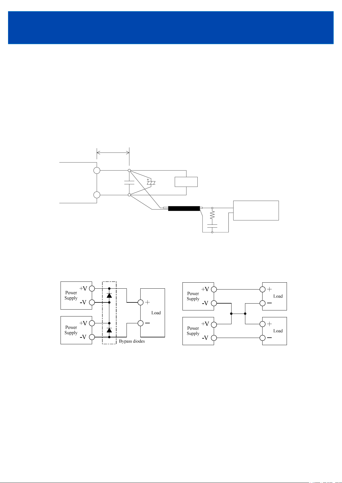
67. Output Ripple & Noise
The standard specification for maximum ripple value is measured according to measurement circuit specified
by JEITARC9131C. When load lines are longer, ripple will becomes larger. In this case, electrolytic capacitor,
film capacitor, etc. might be necessary to use across the load terminal.
The output ripple cannot be measured accurately if the probe ground lead of oscilloscope is too long.
150mm
+V
Power
Supply
C1
C2
V
Coaxial Cable
1.5m 50Ω
68. Series Operation
For series operation, either method (A) or (B) is possible.
Method (A) Method (B)
Load
C1 : 0.1uF Cap., Film
C2 : 100uF
C3 : 4700pF
R1 : 50Ω
R1
C3 Bandwidth : 100MHz
Cap., Elect.
Cap., Ceramic
Oscilloscope
Note : Ensure that all units must be in operation. (Never use in condition that one of the units is not
operated.)
When connected the bypass diode, select a bypass diode with maximum forward current rating more
than output load current. And maximum reveres voltage must withstand each power supply output
voltage.
<Page>
14/28
Page 15

TDKLambda
GXE600 Series
INSTRUCTION MANUAL
69. Parallel Operation
Current balancing function is provided. Both operation modes (A) and (B) are possible.
(A) To increase the output current
Connecting PC to PC terminal and COM to COM terminal, the current balancing function activates and
output current of each power supply is equivalently supplied to load. Wire to PC terminal, COM terminals
shall be as short as possible and same length with twist.
1. Adjust the output voltage of each power supply to be same value within 1%.
2. Use same length and type of wires for all load lines.
3. Parallel operation is possible up to 5 units.
Maximum value of output current in parallel is up to 90% of all paralleled models.
Output current of each power supply must be within output derating.
4.There is a possibility that output voltage dips at dynamic load change.
(B) To Use as a Backup Power Supply (by connecting reverse preventive diode or module “RP6020”.)
1. Adjust the output voltage higher by the value of forward voltage drop (VF) of the diode.
2. Adjust each power supply output voltage to be same.
3. Output voltage and output power should be used within specifications.
4.Use blocking diode to prevent reverse current. Diode current rating must be more than output load current.
(A) (B)
Power
Supply
PC
+V
-V
+S
+Vm
Vm
SCOM
+
Load
-
Power
Supply
+V
-V
+S
+Vm
Vm
S
Io
Vo+Vf
Vo
+
Load
-
PC
Power
Supply
COM
+V
-V
+S
+Vm
Vm
S
Power
Supply
+V
Vo+ Vf
-V
+S
+Vm
Vm
S
610. Remote Sensing (+S, S terminal)
Remote Sensing function is provided.
This function compensates voltage drop of wiring from output terminals to load terminals. Connect "+S" terminal
to "+" terminal of load and "S" terminal to "" terminal of load with sensing wires.
The total line voltage drop (+ side line and side line) shall be less than 0.3V.
In case that sensing line is too long, it is recommended to connect electrolytic capacitor in the following locations:
1) Across the load terminal,
2) Between "+S" terminal and "+Vm" terminal,
3) Between "S" terminal and "Vm" terminal.
Connect "+S" terminal to "+Vm" terminal, "S" terminal to "Vm" terminal with short pieces when remote
sensing function is not used. If disconnected, OVP function might trigger and voltage will be shut down.
+S
+
+Vm
Power
Supply
+V
V
+
+
Load
-
Vm
+
S
<Page>
15/28
Page 16

TDKLambda
GXE600 Series
INSTRUCTION MANUAL
611. Output Current External Control (CC)
Output current external control function is provided. Output current can be varied by applying an
external voltage (1 6V) to “CC” terminal and “COM” terminal. If an external voltage is not applied,
the CC reference is set to 115% of the nominal output current by internal pullup circuit. If external voltage is
more than 5.75V, the CC reference is limited to 115% of the nominal output current.
The CC reference range is 20115%.
The CC reference can also be adjusted by communication function. Refer to “Communication Manual”.
(A) Use as Constant Voltage (CV) power supply
CC function operates as constant current limit at over current condition.
It is recommended that CC reference is set to more than steady output current for response of output rise
and dynamic load change.
(B) Use as Constant Current (CC) power supply
CC reference must be within output derating.
When output voltage is increased to PV reference, output changes to constant voltage (CV) mode. In this
case also, the output power must be within output derating.
The CC reference be able to change to less than 20% of the nominal output current, but it is out of
specifications area. The output current ripple might increase.
115%
100%
20%
CC Reference (%)
0 1 V 5V
CC Voltage (V)
612. Output Voltage External Control (PV)
Output voltage external control function is provided. Output voltage can be varied by applying an
external voltage (1 6V) to “PV” terminal and “COM” terminal. Take note when the output voltage is
increased excessively, the OVP function might operate. If an external voltage is not applied, the output
voltage is set to the voltage that depend on the output voltage adjustment trimmer. PV function have priority
than the output voltage adjustment trimmer for the output voltage setting.
The PV reference range is 20120%.
The PV reference can also be adjusted by communication function. Refer to “Communication Manual”.
The PV reference must be within output derating.
PV reference be able to change to less than 20% of the nominal output voltage, but it is out of specifications
area and certifications of safety standard.
120%
110%
100%
120%
100%
6V
5.75V
Rated
Power
20%
PV Reference(%)
0 1 V 5V 6V
5.5V
PV Voltage (V)
<Page>
16/28
20%
Output Voltage(%)
0 83.3% 100%
Output Current(%)
Page 17

TDKLambda
GXE600 Series
INSTRUCTION MANUAL
613. Power Fail Signal (PF Signal)
Power Fail (low output voltage or current) detection signal is provided. Power Fail (PF) signal will turn
“High” level to indicate the abnormal status when the output voltage drops to less than 80% (default) of rated
value. It is caused by either the drop or brownout of the input voltage, OCP, OVP, OTP operation.
The PF reference can be adjusted and PF sensing has selectable target output voltage or current, by
communication function. Refer to “Communication Manual”.
When the PF signal is “Low”, the output monitoring indicator (LED) lights up.
PF signal is isolated from input and output by a photocoupler. It uses the open collector method shown in
below.
PF
VCE max = 30V
IC max = 20mA
TOG
614. Low Input Voltage Detection Signal
AC Fail Signal
AC Fail signal will turn “High” level to indicate when the input voltage shut down.
AC Fail signal turn “High” at out of the specification (less than 85 VAC).
The delay time (From input shut down to AC Fail signal turn “High”) is less than 15ms. at the condition of
output power is more than 20% of rated output power. The delay time is longer at the output power is less
than 20% of rated output power.
AC Fail signal is isolated from input and output by a photocoupler. It uses the open collector method shown
in below.
AC Fail
VCE max = 30V
IC max = 20mA
TOG
615. External standby supply +STB STB terminal
External standby supply 5V Typ. (4.8–5.2V) and 1A is provided. +/STB terminal is isolated from input and
output, and it is always available as long as input power in the specified voltage range is supplied.
OCP is constant current limit with automatic recovery method.
OCP function operates when the output current exceeds 130% of maximum output current of specification.
The output will be automatically recovered when the overload condition is canceled. Never operate the unit
under over current or shorted conditions, which might leads damage or insulation failure. OCP point is fixed.
OVP is not built in. Never apply higher voltage externally to the output terminal to avoid unit failure. In case
of inductive load, put protective diode in series to the output power line.
<Page>
17/28
Page 18

TDKLambda
GXE600 Series
INSTRUCTION MANUAL
616. Remote ON/OFF Control
Remote ON/OFF control function is provided. Output ON/OFF is allowed to control without input voltage
ON/OFF, dependent on the condition of CN84 (CNT1, CNT2 and TOG terminal).
Remote ON/OFF control circuit is isolated from input and output.
CNT1, CNT2 and TOG are not connected at time of shipment, so power supply output condition is ON.
(1) Input external Voltage_Active
Third_Vcc_5V
SW Output condition
OFF ON
ON OFF
(2) OFF_Active
Third_Vcc_5V
(3) ON_Active
Third_Vcc_5V
CNT1
CNT2
TOG
CNT1
CNT2
TOG
CNT1
SW
Rex
SW
Vex
Connect the external resistor (Rex)
Iex
Decide Vex and Rex so that Iex is 2~5mA.
Decide Rex by following formula.
Rex = ( Vex 1.1 ) / ( Iex )
Vex Rex
4.5 ~ 25.5VDC 680 12k Ω
SW Output condition
OFF ON
ON OFF
SW Output condition
OFF OFF
ON ON
CNT2
TOG
SW
617. Sleep Mode
Sleep mode is provided and it contributes to reduction of standby power when all of the following
conditions are satisfied.
・ Output condition is “OFF” by remote ON/OFF control terminal.
・ Output condition is “OFF” by communication function when CNT mode is “digital CNT”.
・ PF signal is “High”.
・ Protection has not occurred(all of the alarm history indicator register are “0”).
・ The query has not been sent for more than 30 minutes.
In sleep mode, the power supply returns to normal operation by turning remote ON/OFF control to “ON”
or triggering the signal of RS485. Take note that the communication function cannot be used during sleep
mode and power supply cannot receive the signal of RS485. In this case, send the query again.
When a voltage is applied to the output terminal of the power supply from the outside in sleep mode, if the
PF threshold is exceeded, PF signal keeps “High”. Refer to “Communication Manual” for details.
<Page>
18/28
Page 19

TDKLambda
GXE600 Series
INSTRUCTION MANUAL
618. Communication Configuration Switch (SW81)
If the communication configuration (Slave ID, Baud Rate, Parity, Other) is unknown and the communication
function is unusable, reset the configuration as follows. The startingup with default configuration is possible by
SW81.
The SW81 is set at “ENABLE” side at time of shipment.
Step 1: After the AC shut down and cool down the product, set the SW81 to“DISABLE” side.
Step 2: After input the AC, read the communication configuration registers by communication function.
Step 3: Modify the communication configuration registers as necessary.
Step 4: After the AC shut down and cool down the product, set the SW81 to “ENABLE” side.
Refer to “Communication Manual” for details.
Do not touch this product or its internal components while circuit in operation, or shortly after shutdown.
You might receive a burn.
Item Default Setting
Slave ID 1
Baud Rate 19200 bps
Parity Even paryt y
Other Start : 1 bit / Stop : 1 bit / LSB First
Communication Configuration Swtch (SW81)
ENABLE DISABLE
*/A : For the option model with cover,
slide the SW81 from the rectangle hole at side surface
by non conductive tweezers etc..
619. Communication Function (RS485)
Communication function is provided. The physical layer is RS485 and the protocol supports MODBUS.
Refer to “Communication Manual” for details.
<Communication function example>
・Various monitoring function
(Output voltage, Output Current, Converter operation time, Internal temperature)
・Protection history (OCP, OVP, OTP, etc.)
・Protection configuration (Threshold value, Protection mode auto recovery or latch)
・Remaining lifetime of the electrolytic capacitor calculation.
・Real time control of PV reference and CC reference
・Slew rate of the output voltage and current adjustment.
・Remote ON/OFF control and its configuration (CNT mode and CNT terminal input sensitivity)
・Communication configuration (Slave ID, Baud Rate, Parity, Other)
・Product information indication (Model name, Serial No., Lot No., Firmware ver.)
・Scratch Pad (Up to 30 characters of data can be stored in ASCII characters. )
<Page>
19/28
Page 20

TDKLambda
GXE600 Series
INSTRUCTION MANUAL
620. Isolation Test
Isolation resistance between Output terminal is more than 100MΩ at 500VDC. For safety operation, voltage
setting of DC isolation tester must be done before the test. Ensure that the unit is fully discharged after the test.
■ Output terminal : 500VDC More than 100MΩ
+V
V
+Vm
+S
Vm
S
PC
CC
PV
COM
PF
AC Fail
CNT 1
+STB
CNT 2
STB
SG
TOG
+DATA
DATA
Isolation
Tester
L
N
Input
Terminal
Output
Terminal
CN84
621. Withstand Voltage
This series is designed to withstand 4.0kVAC between input and output, 2.0kVAC between input and
terminal, 1.5kVAC between output and terminal and 100VAC between output and PF, TOG, STB, CNT,
AC Fail, DATA, SG terminal each for 1 minute. In the withstand voltage tester, set current limit of the
withstand voltage tester at 20mA.The applied voltage must be gradually increased from zero to test value and
then gradually decreased for shut down. When timer is used, the power supply might be
damaged by high impulse voltage at switch on and off timing. Connection as follows.
■ Input Output : 4.0kVAC 1min(20mA) ■ Output – TOG, etc. : 100VAC 1 min(20mA)
+V
V
+Vm
+S
Vm
S
PC
CC
PV
COM
PF
AC Fail
CNT 1
+STB
CNT 2
STB
SG
TOG
+DATA
DATA
Withstand
Voltage
Tester
Withstand
Voltage
Tester
L
N
Input
Terminal
Output
Terminal
CN84
+V
V
+Vm
+S
Vm
S
PC
CC
PV
COM
PF
AC Fail
CNT 1
+STB
CNT 2
STB
SG
TOG
+DATA
DATA
L
N
Input
Terminal
Output
Terminal
CN84
<Page>
20/28
Page 21

TDKLambda
GXE600 Series
INSTRUCTION MANUAL
■ Output Terminal : 1.5kVAC 1min(20mA) ■ Input – Terminal : 2.0kVAC 1min(20mA)
+V
V
+Vm
+S
Vm
S
PC
CC
PV
COM
PF
AC Fail
CNT 1
+STB
CNT 2
STB
SG
TOG
+DATA
DATA
Withstand
Voltage
Tester
L
N
Input
Terminal
Output
Terminal
CN84
+V
V
+Vm
+S
Vm
S
PC
CC
PV
COM
PF
AC Fail
CNT 1
+STB
CNT 2
STB
SG
TOG
+DATA
DATA
Withstand
Voltage
Tester
L
N
Input
Terminal
Output
Terminal
CN84
Note : In case of using external noise filter, capacitance between "Input and terminal" might be increased.
When testing withstand voltage between "Input and Output", there is a possibility exceeding withstand
voltage between "Output and terminal" (1.5kVAC). Check the voltage between
"Output and terminal". If the voltage exceeding withstand voltage, add external capacitor to
"Output and terminal" in order to decrease the voltage.
On the other hand, no need to check the voltage in case of "Output and terminal" is shorted.
The example of noise filter circuit that
may increases capacitance value
between ”Input and terminal”.
(Capacitance value dashed line is added.)
<Page>
21/28
External capacitor adding point
or short point.
Even in the case of ”+V and ”,
there is a similar effect.
Page 22

TDKLambda
GXE600 Series
INSTRUCTION MANUAL
7. Mounting Method
71. Mounting Method
(1) These models are convection cooling type power supply. As consideration for the heat radiation, keep a
space more than 15mm between the power supply and the peripheral parts.
Also when using multiple units, keep a space more than 15mm from each other.
(2) Use 4 Mount Holes at bottom side.
(3) The maximum allowable penetration of mounting screws is 4mm.
Incomplete thread of mounting screw should not be penetrated.
(4) Recommended torque for mounting screw : 1.2N・m(12.0kgf・cm) ~ 1.6N・m (16.3kgf・cm)
Convective
Airflow
Sheet Metal
15mm or more
15mm or more 15mm or more
Need punching holes for convective airflow
15mm or more
4mm or less
M4 screw(4 points)
<Page>
22/28
15mm or more
4mm or less
Sheet Metal
Page 23

72. Mounting Directions
The standard mounting is direction (A). Direction (B) ~ (D) are also possible.
Never use as mounting direction (E) and (F) shown below.
(A) Standard Mounting
Input
Terminal
(B)
TDKLambda
GXE600 Series
INSTRUCTION MANUAL
There are also mounting holes on this side. However, these
mounting holes do not have strength enough to withstand the
vibration / shock specifications by themselves.
Therefore, Use 4 Mount Holes at bottom side to satisfy that.
(C) (D) (E)Not possible (F)Not possible
<Page>
23/28
Page 24

73. Output Derating
83%(500W)
Refer to the output derating for the standard model below,
■ Convection cooling ( Standard model )
A : Output Current vs. Ta
120
TDKLambda
GXE600 Series
INSTRUCTION MANUAL
100
80
60
40
20
Output Current (%)
0
20 10 0 10 20 30 40 50 60 70 80
Ta (
B : Outp ut Power vs. Input Voltage
120
100
80
60
40
Output Power (%)
20
0
85 115 145 175 205 235 265
100
170
Input Voltage (VAC)
45
o
C)
Mounting (A)(B)(D)
Mounting (C)
Ta
(°C) Mounting (A)(B)(D) Mounting (C)
20≦Ta≦+45 100 100
50 100 90
70 50 50
Input Voltage
(VAC)
85
100<
<170
170
≦
Output Current (%)
Outp ut Power
60% (360W)
83% (500W)
83% (500W)
100% (600W)
Use so that both of A. and B. shall be satisfied.
A : Derating is necessary to output current in case of ambient temperature more than 50°C.
B : Derating is necessary to output power in case of input voltage less than 170VAC.
For example, in case of input voltage 100VAC and ambient temperature 60°C and mounting A at 24V model.
According to A. ambient temperature derating, output current limit is 75% (18.75A).①
According to B. input voltage derating, output power limit is 500W.②
⇒ When Vo ≦ 26.6V, the derating is determined by output current (18.75A) ①.
Because output power is less than 500W (26.6V x 18.75A).
When Vo > 26.6V, the derating is determined by output power (500W) ②
(Caution) The option model with cover (/A) has the different derating vs. ambient temperature from
the standard model. (20 ~ +40°C : Io= 100%, +70°C : Io= 40% for /A option)
Refer to the specification of option model, and be careful the output current limit.
<Page>
24/28
Page 25

■ Forced air cooling
A : Output Current vs. Ta
120
TDKLambda
GXE600 Series
INSTRUCTION MANUAL
100
80
60
40
20
Output Current (%)
0
20 10 0 10 20 30 40 50 60 70 80
o
Ta (
C)
B : Outp ut Power vs. Input Voltage
120
100
80
60
40
20
Output Power (%)
0
85 115 145 175 205 235 265
Input Voltage (VAC)
Ta
(°C)
20≦Ta≦+50
70
Input Voltage
(VAC)
85~265
Forced air cooling
Output Current (%)
Forced air cooling
Output Power
100% (600W)
Use so that both of A. and B. shall be satisfied.
A : Derating is necessary to output current in case of ambient temperature more than 50°C.
B : Derating is unnecessary to output power in input voltage range 85265VAC.
100
50
For example, in case of input voltage 100VAC and ambient temperature 60°C at 24V model.
According to A. ambient temperature derating, output current limit is 75% (18.75A).①
According to B. input voltage derating is unnecessary, output power limit is 600W.②
⇒ If Vo=28.8V (max.), the derating is determined by output current (18.75A) ①.
Because output power is less than 600W (28.8V x 18.75A = 540W).
In forced air condition, the entire components shall be cooled.
Temperature of L2 and L5 need to be less than 85 °C.
As reference, set wind velocity at 1.0m/s (height of space at 50mm. our test condition).
Choke coil allowable Max. temperature
Allowable Max. temperature
L2 L5
85°C 85°C
Monitoring point
L2: Top of core case
L5: Side of core
L2
L5
<Page>
25/28
Page 26

TDKLambda
020406080
100
120
020406080
100
120
140
GXE600 Series
INSTRUCTION MANUAL
The output voltage adjustment by PV function or “output voltage adjustment trimmer” ,
and the output current adjustment by CC function are provided.
Use the CC function within “output current vs. output voltage” and output derating.
For reference, Operating area of standard model at Mounting (A), (B), (D) and Forced air cooling condition
are as follows.
50°C
60°C
Output voltage vs. Output current
[170VAC≦Vin≦265VAC] convection
[85VAC≦Vin≦265VAC] Forced air
140
Output voltage vs. Output current
[100VAC≦Vin≦170VAC] convection
70°C
120
600W
120
500W
100
80
60
Output Voltage (%)
40
20
50%
0
75%
Output Current (%)
Output voltage vs. Output current
出力電圧 vs. 出力電流
[85VAC≦Vin≦100VAC] convection
[85VAC≦Vin≦100VAC] 自然空冷
140
120
100
Po(W) = 9.33 × Vin 433
85VAC
100
80
60
40
Output Voltage (%)
20
75%50%
0
0 20 40 60 80 100 120
Output Current (%)
example
80
60
Output Voltage (%)
40
20
75%50%
0
Output Current (%)
(Caution) The option model with cover (/A) has the different derating vs. ambient temperature from
the standard model. (20 ~ +40°C : Io= 100%, +70°C : Io= 40% for /A option)
It means the operation area is also difference.
Refer to the specification of option model, and be careful the output current limit.
<Page>
26/28
Page 27

TDKLambda
Recommended crimpty p e terminal
GXE600 Series
INSTRUCTION MANUAL
8. Wiring Method
(1) The output load line and input line shall be separated, and use all lines as thick and short as possible to make
lower impedance. The output load line and input line shall be twisted or use shielded wire to improve noise
sensitivity.
(2) Remote sensing lines and remote ON/OFF control lines shall be twisted and separated from the output lines.
(3) Noise can be reduced by attaching a capacitor to the load terminals.
(4) The recommended wire type, torque and crimptype terminal :
Model
GXE600
Recommended
Wire
AWG1222
Recommended torque
Input terminal M3.5 Screws
1.0Nꞏm (10.2kgfꞏcm ~ 1.6Nꞏm (16.3kgfꞏcm)
Outp ut terminal M4 Screws
1.2Nꞏm (12.0kgfꞏcm) ~ 1.6Nꞏm (16.3kgfꞏcm)
D
(MAX)t(MAX)
8.1mm
1.0mm 1piece
0.8mm 2pieces
Mounting piecs
Note : Recommended wire type and crimptype terminal vary depending
on use conditions. Choice most appropriate wire type and
crimptype terminal by referring to wire maker recommended
allowable current and voltage drop.
9.The life expectancy
The life of the power supply depends on the life of the builtin aluminum electrolytic capacitor. The life is
described in reliability data.
The life of the aluminum electrolytic capacitor varies depending on the method of mounting the power supply,
the load current and the ambient temperature. Please refer to “Electrolytic Capacitor Lifetime”.
Please do not use the product which passed over the life expectancy. There is a risk of unexpected output
shutdown and specifications might not be satisfied.
Please contact us for maintenance or exchange the product which passed over the life expectancy.
(MAX)
10. External Fuse Rating
Refer to the following fuse rating when selecting the external input fuse.
Surge current flows when input turn on. Use slowblow fuse or timelug fuse. Fastblow fuse cannot be used.
Fuse rating is specified by inrush current value at input turn on.
Do not select the fuse according to actual input current (rms.) values.
GXE600 : 12.5A
<Page>
27/28
Page 28

11. Before concluding that the unit is at fault…
(1) Check if the rated input voltage is connected.
(2) Check if the wiring of input and output is correct.
(3) Check if the wire size is not too thin.
(4) Check if the output voltage adjustment trimmer is properly adjusted.
OVP function might operate.
(5) Check if the Remote sensing terminal is not opened.
OVP function might trigger and output voltage will be shut down.
(6) Check if the output current and output power are not over specifications.
(7) Audible noise can be heard when input voltage waveform is not sinusoidal wave.
(8) Audible noise can be heard at a DynamicLoad operating frequency.
(9) Check if the communication configuration is correct value.
When PV reference or CC reference is too small, or more than protection point, OVP or OCP might trigger
and output voltage will be shut down.
(10)Check if the power supply is not the sleep mode.
The communication function cannot be used during sleep mode.
(11)Ensure that large capacitor is not connected on the output side.
Use within 10,000uF as the output might shut down or be unstable operation.
Contact us, if connecting more than 10,000uF.
For capacitive loads such as batteries, use the CC function within output derating.
TDKLambda
GXE600 Series
INSTRUCTION MANUAL
12. Warranty Period
This product is warranted for a period of 5 years from the date of shipment.
For damages occurring at normal operation within this warranty period, repair is free of charge.
Please read the General Safety Instruction before using the products.
<Page>
28/28
 Loading...