

TDK-Lambda Genesys Series, G/P-2U-10V, G/P-2U-60-100V, G/P-2U-20-40V, G/P-2U-150-600V Instruction Manual
...Page 1

Series
Programmable DC Power Supplies
G1.7 ÷ 5kW in 1U 0-600V / 0-500A
The manual covers kit options:
G/P-2U-10V
G/P-2U-20-40V
G/P-2U-60-100V
G/P-2U-150-600V
PARALLEL KIT INSTRUCTION MANUAL
IA876-04-01A
*Z0022570*
Z0022570
Page 2
2
1.1
General
Parallel kit is supplied separately from the power supply packing according to order.
The usage of parallel kit is according to customer's needs.
1.2
Advanced Parallel
For parallel connection, refer to advanced parallel chapter in the series User Manual.
1.3
Product Safety Instructions
Safety approvals are valid for single unit only. These are not valid for parallel kit assembly.
When using a paralleling kit with a protective bracket, it must be correctly assembled, as described further in this
document.
1.4
Assembly Instructions
The supplied kit is used for standard and blank panel options. Follow the instructions carefully according to power
supply model.
1.4.1 G/P-2U-10V - Assembly Instructions for two 10V units in Parallel
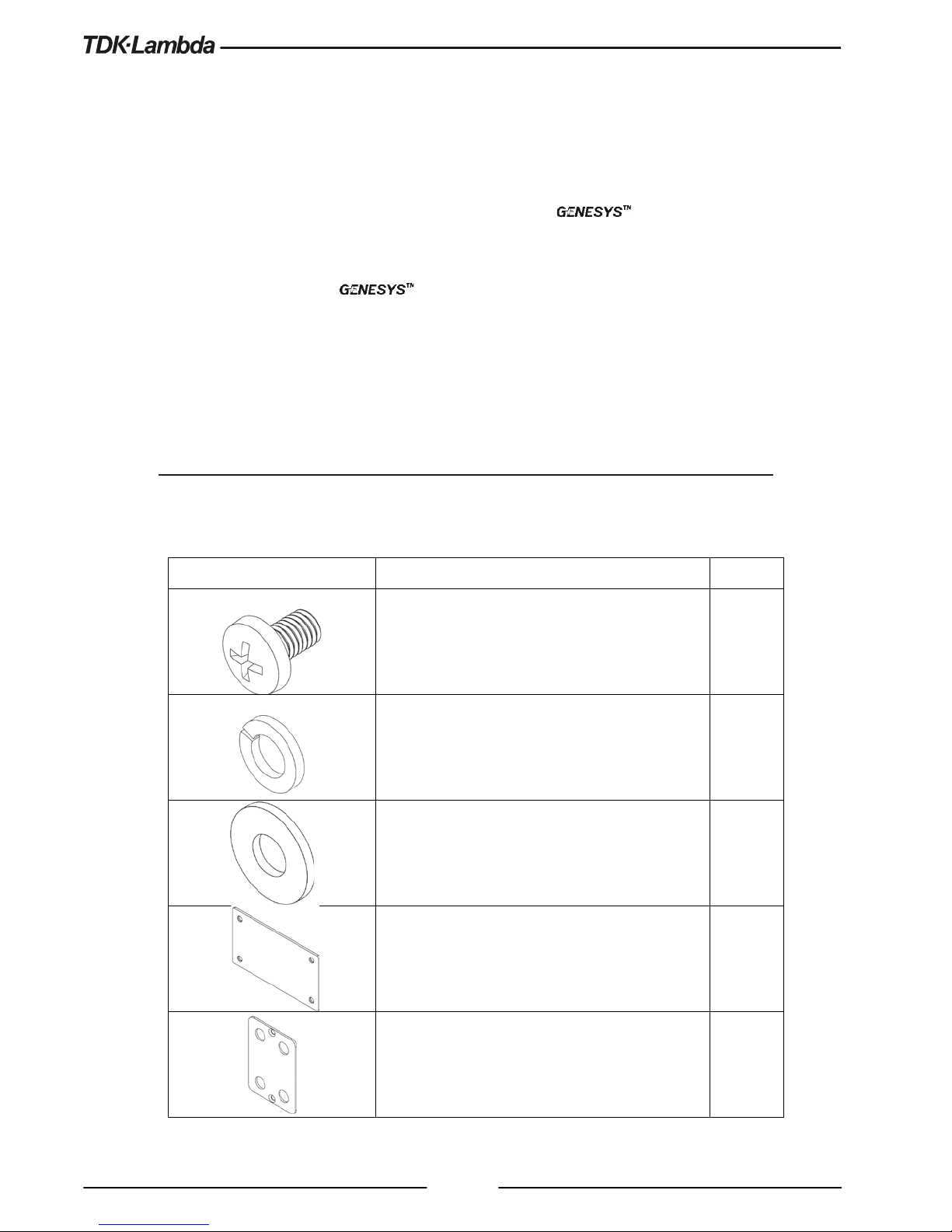
1.4.1.1 Components List
Image Component Quantity
10-32 x 5/16 Pan Head Screw, Stainless Steel 8
Helical Spring-Lock Washer, No. 10, Stainless Steel 8
Plain Washer, No. 10, Stainless Steel 8
Connection Plate 2U 2
Output Short 2
Page 3
3
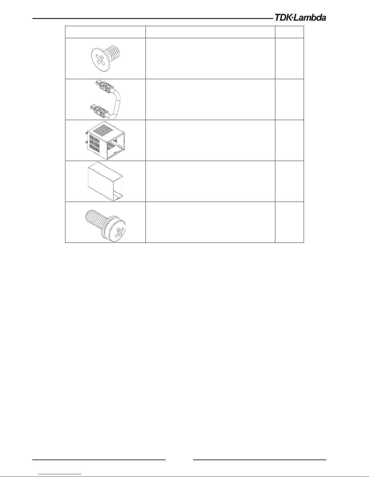
Image Component Quantity
M3 x 4C Flat Head Screw, Nickel Plated 4
Paralleling Cable 1
Output Cover 1
Bus Bar Insulator 2
M3 x 8 SEMS Screw, Nickel Plated 4
Page 4
4
1.4.1.2 Installation Steps
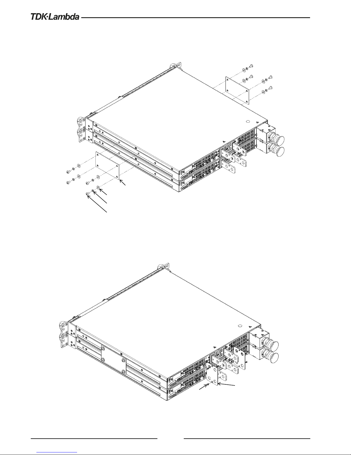
1. Attach connection plates, one on each side of the power supplies, using eight pan head screws, eight helical
spring-lock washers and eight plain washers as illustrated in Figure 1.
Figure 1: Two 10V Units Connection Plates 2U Assembly
2. Attach output short plates, one on each pair of terminals, using four flat head screws as illustrated in
Figure 2.
Figure 2: Two 10V Units Output Short Plates Assembly
Connection Plate 2U
Plain Washer, No. 10, Stainless Steel
Helical Spring-Lock Washer, No. 10, Stainless Steel
10-32 x 5/16 Pan Head Screw, Stainless Steel
Tightening torque: 25.4-31.7 Lbf-inch (2.87-3.58Nm).
M3 x 4C Flat Head Screw, Nickel Plated
Tightening torque: 4.7-5.7 Lbf-inch (0.53-0.64Nm)
Output Short
Page 5
5
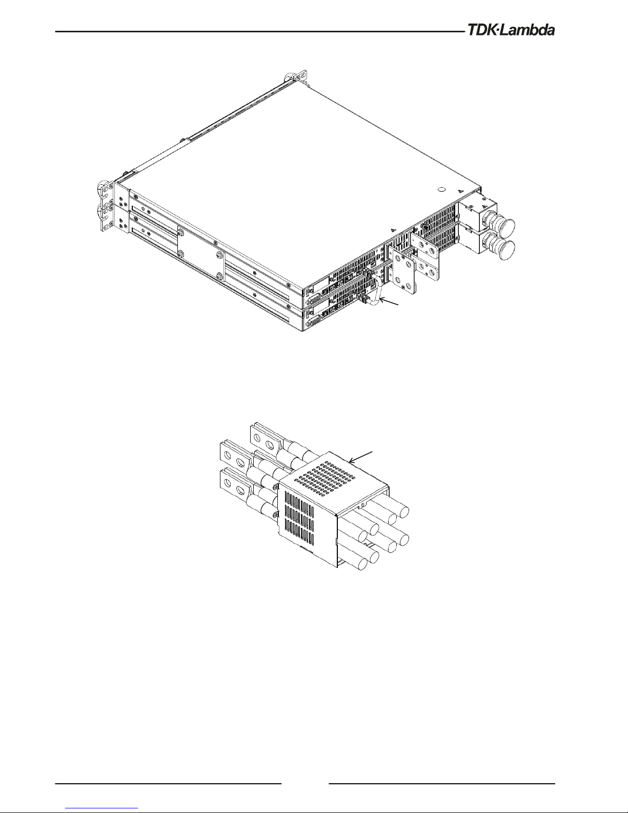
3. Connect paralleling cable from top unit M connector to bottom unit S connector as illustrated in Figure 3.
Figure 3: Two 10V Units Paralleling Cable Connection
4. Insert output cover through the cables as illustrated in Figure 4.
Figure 4: Output Cover Insertion
Paralleling Cable
Output Cover
Page 6

6
5. Assemble two lugs on each bus bar, one on each side, using two hexagon bolts, four plain washers, two
helical spring-lock washers and two hexagon nuts as illustrated in Figure 5.
Figure 5: Two 10V Units Lugs Assembly
6. Assemble bus bar insulator prior to output cover assembly. The insulator is flexible and could be opened in
its bottom side. Open the insulator and cover the bus bar by sliding it over the bus bar, from top to bottom,
as illustrated in Figure 6. Repeat for the second bus bar.
Figure 6: Two 10V Units Bus Bar Insulator Assembly
For recommended lugs refer
to series Safety &
Installation Manual.
Not supplied.
Hexagon Nut, M10, Stainless Steel
Helical Spring-Lock Washer, M10, Stainless Steel
Plain Washer, M10, Stainless Steel
M10 x 25 Hexagon Bolt, Stainless Steel
Tightening torque: 220-265 Lbf-inch (24.9-29.9 Nm)
Bus Bar Insulator
Page 7

7
7. Fix output cover to the power supplies using four SEMS screw as illustrated in Figure 7.
Figure 7: Two 10V Units Output Cover Assembly
M3 x 8 SEMS Screw, Nickel Plated
Tightening torque: 4.7-5.7 Lbf-inch (0.53-0.64Nm)
Page 8

8
1.4.2 G/P-2U-20-40V - Assembly Instructions for two 20V÷40V units in Paralle l
1.4.2.1 Components List
Image Component Quantity
10-32 x 5/16 Pan Head Screw, Stainless Steel 8
Helical Spring-Lock Washer, No. 10, Stainless Steel 8
Plain Washer, No. 10, Stainless Steel 8
Connection Plate 2U 2
Output Short 2
M3 x 4C Flat Head Screw, Nickel Plated 4
Paralleling Cable 1
Output Cover 1
Page 9

9
Image Component Quantity
Bus Bar Insulator 2
Protection Insulator
1
M3 x 8 SEMS Screw, Nickel Plated 6
Page 10

10
1.4.2.2 Installation Steps
1. Attach connection plates, one on each side of the power supplies, using eight pan head screws, eight helical
spring-lock washers and eight plain washers as illustrated in Figure 8.
Figure 8: Two 20V÷40V Units Connection Plates 2U Assembly
2. Attach output short plates, one on each pair of terminals, using four flat head screws as illustrated in
Figure 9.
Figure 9: Two 20V÷40V Units Output Short Plates Assembly
Connection Plate 2U
Plain Washer, No. 10, Stainless Steel
Helical Spring-Lock Washer, No. 10, Stainless Steel
10-32 x 5/16 Pan Head Screw, Stainless Steel
Tightening torque: 25.4-31.7 Lbf-inch (2.87-3.58Nm).
M3 x 4C Flat Head Screw, Nickel Plated
Tightening torque: 4.7-5.7 Lbf-inch (0.53-0.64Nm)
Output Short
Page 11

11
3. Connect paralleling cable from top unit M connector to bottom unit S connector as illustrated in Figure 10.
Figure 10: Two 20V÷40V Units Paralleling Cable Connection
4. Insert output cover through the cables as illustrated in Figure 11.
Figure 11: Output Cover Insertion
Paralleling Cable
Output Cover
Page 12

12
5. Assemble one lug on each bus bar using two hexagon bolts, four plain washers, two helical spring-lock
washers and two hexagon nuts as illustrated in Figure 12.
Figure 12: Two 20V÷40V Units Lugs Assembly
6. Assemble bus bar insulator prior to output cover assembly. The insulator is flexible and could be opened in
its bottom side. Open the insulator and cover the bus bar by sliding it over the bus bar, from top to bottom,
as illustrated in Figure 13. Repeat for the second bus bar.
Figure 13: Two 20V÷40V Units Bus Bar Insulator Assembly
For recommended lugs refer
to series Safety &
Installation Manual.
Not supplied.
Hexagon Nut, M10, Stainless Steel
Helical Spring-Lock Washer, M10, Stainless Steel
Plain Washer, M10, Stainless Steel
M10 x 25 Hexagon Bolt, Stainless Steel
Tightening torque: 220-265 Lbf-inch (24.9-29.9 Nm)
Bus Bar Insulator
Page 13

13
7. Fix output cover to the power supplies using four SEMS screw as illustrated in Figure 14.
Figure 14: Two 20V÷40V Units Output Cover Assembly
8.
Fix protection insulator to the output cover using two SEMS screw as illustrated in Figure 15.
Figure 15: Two 20V÷40V Units Protection Insulator Assembly
M3 x 8 SEMS Screw, Nickel Plated
Tightening torque: 4.7-5.7 Lbf-inch (0.53-0.64Nm)
Protection Insulator
M3 x 8 SEMS Screw, Nickel Plated
Tightening torque: 4.7-5.7 Lbf-inch (0.53-0.64Nm)
Page 14

14
1.4.3 G/P-2U-60-100V - Assembly Instructions for two 60V÷100V units in
Parallel
1.4.3.1 Components List
Image Component Quantity
10-32 x 5/16 Pan Head Screw, Stainless Steel 8
Helical Spring-Lock Washer, No. 10, Stainless Steel 8
Plain Washer, No. 10, Stainless Steel 8
Connection Plate 2U 2
Output Short 2
M3 x 4C Flat Head Screw, Nickel Plated 4
Paralleling Cable 1
Output Cover 1
Page 15

15
Image Component Quantity
Bus Bar Protection Bracket 1
Bus Bar Cover Plug 4
M3 x 8 SEMS Screw, Nickel Plated 6
Page 16

16
1.4.3.2 Installation Steps
1. Attach connection plates, one on each side of the power supplies, using eight pan head screws, eight helical
spring-lock washers and eight plain washers as illustrated in Figure 16.
Figure 16: Two
60V÷100V Units Connection Plates 2U Assembly
2. Attach output short plates, one on each pair of terminals, using four flat head screws as illustrated in
Figure 17.
Figure 17: Two 60V÷100V Units Output Short Plates Assembly
Connection Plate 2U
Plain Washer, No. 10, Stainless Steel
Helical Spring-Lock Washer, No. 10, Stainless Steel
10-32 x 5/16 Pan Head Screw, Stainless Steel
Tightening torque: 25.4-31.7 Lbf-inch (2.87-3.58Nm).
M3 x 4C Flat Head Screw, Nickel Plated
Tightening torque: 4.7-5.7 Lbf-inch (0.53-0.64Nm)
Output Short
Page 17

17
3. Connect paralleling cable from top unit M connector to bottom unit S connector as illustrated in Figure 18.
Figure 18: Two 60V÷100V Units Paralleling Cable Connection
4. For load wires with a diameter smaller than or equal to 11 millimeter insert four bus bar cover plugs into
the bus bar protection bracket and fix it to the output cover using two SEMS screw. Insert output cover
assembly through the cables as illustrated in Figure 19.
Figure 19: Two 60V÷100V Units, Wire Diameter ≤ 11mm, Output Cover Assembly
Paralleling Cable
Output Cover Assembly
Bus Bar Cover Plug
Bus Bar Protection Bracket
M3 x 8 SEMS Screw, Nickel Plated
Tightening torque: 4.7-5.7 Lbf-inch (0.53-0.64Nm)
Output Cover
Page 18

18
5. For load wires with a diameter greater than 11 millimeter divide each bus bar cover plug into two separate
parts by bending and breaking it along its separate grooves, as illustrated in Figure 20. Insert only the
rounded parts into the bus bar protection bracket and fix it to the output cover using two SEMS screw.
Insert output cover assembly through the cables as illustrated in Figure 20.
Figure 20: Two 60V÷100V Units, Wire Diameter > 11mm, Output Cover Assembly
6. Assemble one lug on each bus bar using one hexagon bolt, two plain washers, one helical spring-lock
washer and one hexagon nut as illustrated in Figure 21.
Figure 21: Two 60V÷100V Units Lugs Assembly
Separate Grooves
Bus Bar Protection Bracket
Bus Bar Cover Plug
M3 x 8 SEMS Screw, Nickel Plated
Tightening torque: 4.7-5.7 Lbf-inch (0.53-0.64Nm)
Output Cover
Output Cover Assembly
For recommended lugs refer
to series Safety &
Installation Manual.
Not supplied.
Hexagon Nut, M8, Stainless Steel
Helical Spring-Lock Washer, M8, Stainless Steel
Plain Washer, M8, Stainless Steel
M8 x 25 Hexagon Bolt, Stainless Steel
Tightening torque: 106-132 Lbf-inch (12-14.9 Nm)
Page 19

19
7. Fix output cover to the power supplies using four SEMS screw as illustrated in Figure 22.
Figure 22: Two 60V÷100V Units Output Cover Assembly
1.4.4 G/P-2U-150-600V - Assembly Instructions for two 150V÷600V units in
Parallel
1.4.4.1 Components List
Image Component Quantity
10-32 x 5/16 Pan Head Screw, Stainless Steel 8
Helical Spring-Lock Washer, No. 10, Stainless Steel 8
Plain Washer, No. 10, Stainless Steel 8
Connection Plate 2U 2
Paralleling Cable 1
M3 x 8 SEMS Screw, Nickel Plated
Tightening torque: 4.7-5.7 Lbf-inch (0.53-0.64Nm)
Page 20

20
1.4.4.2 Installation Steps
1. Attach connection plates, one on each side of the power supplies, using eight pan head screws, eight helical
spring-lock washers and eight plain washers as illustrated in Figure 23.
Figure 23: Two
150V÷600V Units Connection Plates 2U Assembly
2. Connect paralleling cable from top unit M connector to bottom unit S connector as illustrated in Figure 24.
Figure 24: Two 150V÷600V Units Paralleling Cable Connection
Connection Plate 2U
Plain Washer, No. 10, Stainless Steel
Helical Spring-Lock Washer, No. 10, Stainless Steel
10-32 x 5/16 Pan Head Screw, Stainless Steel
Tightening torque: 25.4-31.7 Lbf-inch (2.87-3.58Nm).
Paralleling Cable
 Loading...