

Page 1

TECHNICAL MANUAL FOR
GENESYS
TM
750W/1500W
Programmable DC Power Supplies
Document: 83
-
507-013 Rev D
TDK
-
Lambda Americas Inc.
405 Essex Road, Neptune, NJ 07753
Tel:
(732) 922
-
9300
Fax:
(732) 922
-
9334
Web:
www.US.TDK
-
Lambda.com/HP
Page 2

Page 3

Page 4

83-507-013 Rev. D
GENESYS™ Manual Supplement
FOR UN
ITS EQUIPPED WITH “IEMD” OPTION,
ALSO REFER TO MANUAL 83
-
030
-
200 IEMD.
FOR UNITS EQUIPPED WITH “LAN” OPTION,
REFER TO MANUAL 83
-
034
-
100.
Page 5

83-507-013 Rev. D
TABLE OF CONTENTS
WARRANTY………………………………………………………………………
…………………….
Pg. 1
SAFETY INSTRUCTIONS……………………………………………………………………………..
Pg. 2
GERMAN SAFETY INSTRUCTIONS…………………………………………………………………
Pg. 4
CHAPTER 1 GENERAL INFORMATION
…………………………………………………………...
Pg. 6
1.1 USER MANUAL CONTENT……………………………………………………………………….
Pg.61.2 INTRODUCTION……………………………………………………………………………………
Pg. 6
1.2.1 General descri
p
tion…………………………………………………………………………..
Pg. 6
1.2.2 Models covered ……………………………………………………………………………...
Pg. 6
1.2.3 Features and options ……………………………………………………………………….
.
Pg. 6
1.2.4 Multiple output power system ………………………………………………………………
Pg. 7
1.2.5 Control via the serial communication port…………………………………………………
Pg. 7
1.2.6 Analog voltage programming and monitoring…………………………………………….
Pg. 7
1.2.7 Par
allel oper
a
tion…………………………………………………………………………….
Pg. 7
1.2.8 Output connections………………………………………………………………………….
Pg. 7
1.2.9 Cooling and mechanical construction……………………………………………………..
Pg. 8
1.3 ACCESSORIES…………………………………………………………………………………….
Pg. 8
1.3.1 Included Accessories………………………………………………………………………..
Pg. 8
1.3.2 Optional Communication Cables……………………………………………………………
Pg. 8
1.3.3 AC cables …………………………………………………………………………………….
Pg. 8
CHAPTER 2 SPECIFICATIONS
……………………………………………………………………
...
Pg. 9
2.1 OUTPUT RATING………………………………………………………………………………….
Pg. 9
2.2 INPUT CHARACTERISTICS……………………………………………………………………...
Pg. 9
2.3 CONSTANT VOLTAGE MODE…………………………………………………………………...
Pg. 9
2.4 CONSTANT CURRENT MODE…………………………………………………………………..
Pg. 9
2.5 A
NALOG PROGRMAMING AND MONITORING……………………………………………….
Pg. 9
2.6 PROGRAMMING AND READBACK……………………………………………………………..
Pg. 10
2.7 PROTECTIVE FUNCTIONS………………………………………………………………………
Pg. 10
2.8 FRONT PANEL…………………………………………………………………………………….
Pg. 10
2.9 ENVIRONMENTAL
CONDITIONS……………………………………………………………….
Pg. 10
2.10 MECHANICAL…………………………………………………………………………………….
Pg. 10
2.11 SAFETY/EMS……………………………………………………………………………………..
Pg. 10
2.12 SUPPLEMENTAL CHARACTERISTICS……………………………………………………….
Pg. 11
2.13 OUTLINE DRAWINGS………………………………
…………………………………………...
Pg. 12
CHAPTER 3 INSTALLATION………………………………………………………………………..
Pg. 13
3.1 GENERAL…………………………………………………………………………………………...
Pg. 13
3.2 PREPARATION FOR USE………………………………………………………………………...
Pg. 13
3.3 INITIAL INSPECTION…………………………………………………………
…………………...
Pg. 13
3.4 RACK MOUNTING…………………………………………………………………………………
Pg. 13
3.4.1 To install the power supply in a rack……………………………………………………..
Pg. 13
3.4.2 Rack mount slides………………………………………………………………………….
Pg. 14
3.5 LOCATION MOUNTING AND COOL
ING……………………………………………………….
Pg. 14
3.6 AC SOURCE REQUIREMENTS………………………………………………………………….
Pg. 14
3.7 AC INPUT POWER CONNECTION……………………………………………………………...
Pg. 14
3.7.1 AC input connector, 1500W mo
d
els………………………………………………………
Pg. 15
3.7.2 AC input
connector, 750W mo
d
els………………………………………………………..
Pg. 15
3.7.3 AC input cord………………………………………………………………………………..
Pg. 15
3.7.4 AC input wire connection, 1500W mo
d
els………………………………………………..
Pg. 15
3.8 TURN
-
ON CHECKOUT PROCEDURE………………………………………………………….
P
g. 16
3.8.1 Ge
n
eral……………………………………………………………………………………….
Pg. 16
3.8.2 Prior to oper
a
tion…………………………………………………………………………….
Pg. 16
3.8.3 Constant voltage check……………………………………………………………………..
Pg. 17
3.8.4 Constant current check………………………
……………………………………………..
Pg. 17
3.8.5 OVP check…………………………………………………………………………………...
Pg. 17
3.8.6 UVL check……………………………………………………………………………………
Pg. 17
3.8.7 Foldback check……………………………………………………………………………...
Pg. 18
Page 6

83-507-013 Rev. D
TABLE OF CONTENTS
3.8.
8 Address se
t
ting……………….……………………………………………………………..
Pg. 18
3.8.9 Baud rate se
t
ting…………………………………………………………………………….
Pg. 18
3.9 CONNECTING THE LOAD………………………………………………………………………..
Pg. 18
3.9.1 Load Wi
r
ing…………………………………………………………………………………..
Pg. 18
3.9.2 Current Carrying Capa
c
ity………………………………………………………………….
Pg. 18
3.9.3 Wire termination…………………………………………………………………………….
Pg. 19
3.9.4 Noise and Impedance E
f
fects……………………………………………………………...
Pg. 20
3.9.5 Inductive loads……………………………………
………………………………………….
Pg. 20
3.9.6 Making the load conne
c
tions……………………………………………………………….
Pg. 20
3.9.7 Connecting single loads, local sensing (d
e
fault)…………………………………………
Pg. 23
3.9.8 Connecting single loads, remote sen
s
ing………………………………………………
...
Pg. 23
3.9.9 Connecting multiple loads, radial distribution method…………...……………………...
Pg. 23
3.9.10 Multiple loads connection with distribution term
i
nals…………………………………..
Pg. 24
3.9.11 Grounding ou
t
puts…………………………………………………………………………
Pg. 24
3.10 LOCAL AND REMOTE SENSING………………………………………………………………
Pg. 25
3.10.1 Sensing wi
r
ing……………………………………………………………………………...
Pg. 25
3.10.2 Local sen
s
ing……………………………………………………………………………….
Pg. 25
3.10.3 Remote sen
s
ing…………………………………………………………
…………………
Pg. 26
3.10.4 J2 sense connector technical inform
a
tion………………………………………………
Pg. 26
3.11 REPACKAGING FOR SHIPMENT………………………………………………………………
Pg. 26
CHAPTER 4 FRONT AND REAR PANEL CONTROLS AND CONNECTORS
………...………
Pg. 27
4.1 INTRODUCTION……………
………………………………………………………………………
Pg. 27
4.2 FRONT PANELCONTROLS AND INDICATORS……………………………………………….
Pg. 27
4.3 REAR PANELCONNECTIONS AND CONTROLS……………………………………………..
Pg. 29
4.4 REAR PANEL SW1 SETUP SWITCH……………………………………………………………
Pg. 30
4.4.1 SW1 position
s fun
c
tions……………………………………………………………………
Pg. 31
4.4.2 Resetting the SW1 switch………………………………………………………………
Pg. 31
4.5 REAR PANEL J1 PROGRAMMING AND MONITORING CONNECTOR……………………
Pg. 32
4.5.1 Making J1 conne
c
tions……………………………………………………………………..
Pg. 32
CHAPTER 5 LOCAL OPERATION
………………………………………………………………….
Pg. 34
5.1 INTRODUCTION…………………………………………………………………………………..
Pg. 34
5.2 STANDARD OPERATION…………………………………………………………………………
Pg. 34
5.2.1 Constant Voltage Mode…………………………………………………………………….
Pg. 34
5.2.2 Constant Current Oper
a
tion………………………………………………………………..
Pg. 34
5.2.3 Automatic Cros
s
over………………………………………………………………………..
Pg. 35
5.3 OVER VOLTAGE PROTECTION (OVP)………………………………………………………...
Pg. 35
5.3.1 Setting the OVP level………………………………………
……………………………….
Pg. 35
5.3.2 Activated OVP protection indic
a
tions……………………………………………………..
Pg. 35
5.3.3 Resetting the OVP ci
r
cuit…………………………………………………………………..
Pg. 35
5.4 UNDER VOLTAGE LIMIT……………………………………………………………………….. .
Pg. 36
5.4.1 Sett
ing the UVL level………………………………………………………………………..
Pg. 36
5.5 FOLDBACK PROTECTION……………………………………………………………………….
Pg. 36
5.5.1 Setting the Foldback prote
c
tion…………………………………………………………….
Pg. 36
5.5.2 Resetting activated Foldback prote
c
tion……………………………………
……………..
Pg. 36
5.6 OUTPUT ON/OFF CONTROL…………………………………………………………………….
Pg. 36
5.7 OUTPUT SHUT
-
OFF (SO) CONTROL VIA REAR PANEL J1 CONNECTOR………………
Pg. 36
5.8 ENABLE/DISABLE CONTROL VIA………………………………………………………………
Pg. 37
5.9 CV/CC SIGNAL…………………………………………………………………
…………………..
Pg. 37
5.10 PS OK SIGNAL……………………………………………………………………………………
Pg. 37
5.11 SAFE START AND AUTO
-
RESTART MODES………………………………………………..
Pg. 38
5.11.1 Automatic start mode………………………………………………………………………
Pg. 38
5.11.2 Safe start mode…………………………………………
…………………………………..
Pg. 38
5.12 OVER TEMPERATURE PROTECTION (OTP)………………………………………………..
Pg. 38
5.13 LAST SETTING MEMORY………………………………………………………………………
Pg. 38
5.14 SERIES OPERATION…………………………………………………………………………….
Pg. 39
5.14.1 Series connection for increased
output vol
t
age…………………………………………
Pg. 39
5.14.2 Series connection for positive and negative output vol
t
age……………………………
Pg. 40
5.15 PARALLEL OPERATION……………………………………………………………………….
Pg. 41
Page 7

83-507-013 Rev. D
TABLE OF CONTENTS
5.15.1 Basic parallel operation……………………………
………………………………………
Pg. 41
5.15.2 Advanced parallel operation………………………………………………………………
Pg. 42
5.16 DAISY
-
CHAIN SHUT
-
OFF CONNECTION…………………………………………………….
Pg. 45
5.17 FRONT PANEL LOCKING……………………………………………………………………….
Pg. 44
5.17.1 Unlocked front pan
el………………………………………………………………………
Pg. 44
5.17.2 Locked front panel…………………………………………………………………………
Pg. 44
CHAPTER 6 REMOTE ANALOG PROGRAMMING………………………………………………
Pg. 45
6.1 INTRODUCTION……………………………………………………………………………………
Pg. 45
6.2 LOCAL/REMOTE ANALOG CO
NTROL…………………………………………………………
Pg. 45
6.3 LOCAL/REMOTE ANALOG INDICATION……………………………………………………….
Pg. 45
6.4 REMOTE VOLTAGE PROGRAMMING OF OUTPUT VOLTAGE AND CURRENT………..
Pg. 46
6.5 RESISTIVE PROGRAMMING OF OUTPUT VOLTAGE AND CURRENT…………………..
Pg. 47
6.6 REMO
TE MONITORING OF OUTPUT VOLTAGE AND CURRENT………………………...
Pg. 48
CHAPTER 7 RS232 & RS485 REMOTE CONTROL
……………………………………………...
Pg. 49
7.1 INTRODUCTION……………………………………………………………………………………
Pg. 49
7.2 CONFIGURATION………………………………………………………………………………….
Pg. 49
7.2.1 Default se
t
ting………………………………………………………………………………...
Pg. 49
7.2.2 Address se
t
ting……………………………………………………………………………….
Pg. 49
7.2.3 RS232 or RS485 sele
c
tion………………………………………………………………….
Pg. 49
7.2.4 Baud rate se
t
ting……………………………………………………………………
………..
Pg. 49
7.2.5 Setting the unit into Remote or Local mode……………………………………………….
Pg. 49
7.2.6 RS232/458 port at Local mode……………………………………………………………..
Pg. 50
7.2.7 Front panel in Remote mode……………………………………………………………….
Pg. 50
7.3 REAR PANEL
RS232/485 CONNECTOR……………………………………………………….
Pg. 50
7.4 MD MODE OPTION (Factory I
n
stalled)………………………………………………………….
Pg. 51
7.4.1 MD Mode Description……………………………………………………………………….
Pg. 51
7.4.2 MD Mode enable
-
Serial communication mode…………………………………
……….
Pg. 51
7.4.3 MD Mode SRQ……………………………………………………………………………….
Pg. 51
7.4.4 Communication Coll
i
sions…………………………………………………………………..
Pg. 51
7.4.5 MD Mode SRQ Retransmi
s
sion……………………………………………………………
Pg. 51
7.5 CONNECTING POWER SUPPLIES TO RS232
OR RS485 BUS…………………………….
Pg. 52
7.5.1 Single power su
p
ply………………………………………………………………………….
Pg. 52
7.5.2 Multi power supply connection to RS232 or RS485 BUS………………………………..
Pg. 53
7.6 COMMUNICATION INTERFACE PROTOCOL…………………………………………………
Pg. 53
7.6.1 Data fo
r
mat…………………………………………………………………………………...
Pg. 53
7.6.2 Addres
s
ing……………………………………………………………………………………
Pg. 53
7.6.3 End of message……………………………………………………………………………..
Pg. 53
7.6.4 Command r
e
peat…………………………………………………………………………….
Pg. 53
7.6.5 Chec
k
sum…………………………………………………………………………………….
Pg. 53
7.6.6 Acknow
l
edge………………………………………………………………………………….
Pg. 53
7.6.7 Error me
s
sage………………………………………………………………………………..
Pg. 54
7.6.8 Bac
k
space…………………………………………………………………………………….
Pg. 54
7.7 ERROR MESSAGES………………………………………………………………………………
Pg. 54
7.8 COMMAND SET DESCRIPTION…………………………………………………………………
Pg. 54
7.8.1 General guides……………………………………………………………………………….
Pg. 54
7.8.2 Command set categ
o
ries……………………………………………………………………
Pg. 54
7.8.3 Initialization control co
m
mands……………………………………………………………..
Pg. 55
7.8.4 ID control co
m
mands………………………………………………………………………..
Pg. 55
7.8.5 Output control co
m
mands…………………………………………………………………..
Pg. 55
7.9 GLOBAL OUTPUT COMMANDS………………………………………
………………………..
Pg. 57
7.9.1 Ge
n
eral………………………………………………………………………………………..
Pg. 57
7.10 SINGLE BYTE COMMANDS……………………………………………………………………
Pg. 58
7.10.1 Ge
n
eral………………………………………………………………………………………
Pg. 58
7.10.2 Global commands without r
e
sponse……………
………………………………………..
Pg. 58
7.10.3 Global commands with r
e
sponse…………………………………………………………
Pg. 59
7.10.4 Addressed commands with response……………………………………………………
Pg. 59
7.10.5 Addressed commands without response………………………………………………..
Pg. 59
Page 8

83-507-013 Rev. D
TAB
LE OF CONTENTS
7.10.6 Status Control Commands………………………………………………………………..
Pg. 62
7.11 STATUS, ERROR AND SRQ REGISTERS…………………………………………………..
Pg. 62
7.11.1 General Description………………………………………………………………………..
Pg. 62
7.11.2 Conditional Re
gisters………………………………………………………………………
Pg. 63
7.11.3 Service Request: Enable and Event Regi
s
ters………………………………………….
Pg. 64
7.12 SERIAL COMMUNICATION TEST SET
-
UP.………………………………………………….
Pg. 67
CHAPTER 8 ISOLATED ANALOG PROGRAMMING OPTION
…………………………………
Pg
. 68
8.1 INTRODUCTION……………………………………………………………………………………
Pg. 68
8.2 SPECIFICATIONS………………………………………………………………………………….
Pg. 68
8.2.1 0
-
5V/0
-
10V o
p
tion……………………………………………………………………………
Pg. 68
8.2.2 4
-
20mA o
p
tion………………………………………………………………………………..
Pg. 68
8
.3 ISOLATED PROGRAMMING & MONITORING CONNECTOR………………………………
Pg. 69
8.4 SETUP AND OPERATING INSTRUCTIONS……………………………………………………
Pg. 70
8.4.1 Setting up the power supply for 0
-
5V/0
-
10V Isolated Programming and Monito
r
ing…
Pg. 70
8.4.2 Setting up t
he power supply for 4
-
20mA Isolated Programming and Monito
r
ing……..
Pg. 70
CHAPTER 9 MAINTENANCE
………………………………………………………………………...
Pg. 71
9.1 INTRODUCTION……………………………………………………………………………………
Pg. 71
9.2 UNITS UNDER WARRANTY…………………………………………………………
…………...
Pg. 71
9.3 PERIODIC MAINTENANCE……………………………………………………………………….
Pg. 71
9.4 ADJUSTMENT AND CALIBRATION……………………………………………………………..
Pg. 71
9.5 PARTS REPLACEMENT AND REPAIRS………………………………………………………..
Pg. 71
9.6 TROUBLESHOOTING……………………………………………………………………………..
Pg. 71
9.7 FUSE RATING……………………………………………………………………………………...
Pg. 72
Page 9

83-000-016 Rev.
F
WARRANTY
This
TDK
-
Lambda
Americas Inc.
product is warranted against defects in materials and workmanship for
a period of five years from date of shipment. During the warranty period,
TDK
-
Lambda
Americas Inc.
will, at it’s option, either repair or replace
products which prove to be defective.
LIMITATION OF WARRANTY
The warranty shall not apply to defects resulting from improper or inadequate usage or maintenance by
the buyer, buyer supplied products or
interfacing. The warranty shall not apply to defects resulting from
unauthorized modifications, or from operation exceeding the environmental specifications of the
product, or if the QA seal has been removed or altered by anyone other than
TDK
-
Lambda
Ameri
cas
Inc.
authorized personnel.
TDK
-
Lambda
Americas Inc.
does not warrant the buyer’s circuitry or
malfunctions of
TDK
-
Lambda
Americas Inc.
products resulting from the buyer’s circuitry. Furthermore,
TDK
-
Lambda
Americas Inc.
does not warrant any damage occu
rring as a result of the buyer’s circuitry
or the buyer’s
-
supplied products. THIS LIMITED WARRANTY IS IN LIEU OF, AND
TDK
-
LAMBDA
AMERICAS INC
DISCLAIMS AND EXCLUDES, ALL OTHER WARRANTIES, STATUTORY, EXPRESS
OR IMPLIED, INCLUDING, WITHOUT LIMITATION, ANY
WARRANTY OF MERCHANTABILITY OR
FITNESS FOR A PARTICULAR PURPOSE, OR OF CONFORMITY TO MODELS OR SAMPLES.
WARRANTY SERVICE
This product must be returned to an authorized
TDK
-
Lambda
Americas Inc.
service facility for repairs or
other warranty service. For p
roducts returned to
TDK
-
Lambda
Americas Inc.
for warranty service, the
buyer shall prepay shipping charges to
TDK
-
Lambda
Americas Inc
. If the unit is covered under the
foregoing warranty then
TDK
-
Lambda
Americas Inc.
shall pay the shipping charges to retu
rn the
product to the buyer. Refer to Section 3.11 for repackaging for shipment.
DISCLAIMER
The information contained in this document is subject to change without notice.
TDK
-
Lambda
Americas
Inc.
shall not be liable for errors contained in this document
or for incidental or consequential damages
in connection with the furnishing, performance or use of this material. No part of this document may be
photocopied, reproduced or translated into another language without the prior written consent of
TDK
-
Lambda
A
mericas Inc
.
TRADEMARK INFORMATION
Genesys™
power supply is a trademark of
TDK
-
Lambda
Americas Inc.
Microsoft™
and Windows
™
are trademarks of Microsoft Corporation.
THE FCC WANTS YOU TO KNOW
This equipment has been tested and found to comply with the limits for a Class A digital device,
pursuant to Part 15 of the FCC rules. These limits are designed to provide reasonable protection
against harmful interference when the equipment is operated in a commercial environment.
This equipment generates, uses and can radiate radio frequency energy
and, if not installed and used in
accordance with the instructions, may cause harmful interference to radio communications.
Operation of this equipment i
n a residential area is likely to cause harmful interference, in which case
the user will be required to correct the interference at his own expense.
FCC WARNING
Modifications not expressly approved by manufacturer could void the user authority to ope
rate the
equipment under FCC Rules.
1
Page 10

83-507-013 Rev. D
2
SAFETY INSTRUCTIONS
CAUTION
The following safety precautions must be observed during all phases of operation, service and r
e
pair of
this equipment. Fa
ilure to comply with the safety precautions or warnings in this document violates
safety standards of design, manufacture and intended use of this equipment and may i
m
pair the built
-
in prote
c
tions within.
TDK
-
Lambda Americas Inc. Inc. shall not be liable f
or user’s failure to comply with these requirements.
INSTALLATION CATEGORY
The Genesys
TM
power supply series has been evaluated to INSTALLATION CATEGORY II. Install
a
tion
category (over voltage category) II: local level, appliances, portable equipment etc.
With smaller tra
n-
sient over voltage than Installation Category (over voltage category) III.
GROUNDING
This product is a Safety Class 1 instrument. To minimize shock hazard, the instrument chassis must be
connected to an electrical ground. The instrument mu
st be connected to the AC power supply mains
through a three conductor power cable, with the ground wire firmly connected to an electrical ground
(safety ground) at the power outlet.
For instruments designed to be hard
-
wired to the supply mains, the protec
tive earth terminal must be
connected to the safety electrical ground before another connection is made. Any interruption of the
protective ground conductor or disconnection of the protective earth terminal will cause a potential
shock hazard that might ca
use personal injury.
FUSES
Fuses must be changed by authorized TDK
-
Lambda Americas Inc. Inc. service personnel only. For
continued prote
c
tion against risk of fire, replace only with the same type and rating of fuse. Refer to
Chapter 9 for fuse ra
t
ing
s.
INPUT RATINGS
Do not use AC supply, which exceeds the input voltage and frequency rating of this instrument. The
input voltage and frequency rating of the Genesys
TM
power supply series is: 100
-
240V
, 50/60Hz. For
safety reasons, the mains supply voltage
fluctuations should not exceed +/
-
10% of nominal voltage.
LIVE CIRCUITS
Operating personnel must not remove the instrument cover. No internal adjustment or component r
e-
placement is allowed by non
-
TDK
-
Lambda Americas Inc. Inc. qualified personnel. Never re
place co
m-
ponents with power cable connected. To avoid injuries, always disconnect power, discharge circuits
and remove e
x
ternal voltage source before touching components.
PARTS SUBSTITUTIONS & MODIFICATIONS
Parts substitutions and modifications are allowed
by authorized TDK
-
Lambda Americas Inc. Inc. se
r-
vice personnel only. For repairs or modifications, the instrument must be returned to an authorized
TDK
-
Lambda Americas Inc. Inc. service f
a
cility.
WARNING
OUTPUT TERMINALS GROUNDING
There is a potential shock hazard at the RS232/RS485 and the IEEE ports when using power su
p
plies
with ra
ted or combined voltage greater than 400V and the Positive Output of the Power Supply is
grounded. Do Not connect the Positive Output to ground when using the RS232/RS485 or IEEE.
Page 11

83-507-013 Rev. D
3
SAFETY INSTRUCTIONS
ENVIRONMENTAL CONDITIONS
The Genesys
TM
p
ower supply series safety approval applies to the following operating cond
i
tions:
*Indoor use
*Ambient temperature: 0°C to 50°C
*Maximum relative humidity: 90% (no condensation)
*Altitude: up to 3000m
*Pollution degree 2
CAUTION Risk of Electric
al Shock
Instruction manual symbol. The instrument will be marked with this symbol when it is
necessary for the user to refer to the instruction manual.
Indicates hazardous voltage.
Indicates ground terminal.
Protective Ground Conductor Termin
al
Off (Supply)
On (Supply)
The WARNING sign denotes a hazard. An attention to a procedure is called. Not fo
l-low
ing procedure correctly could result in personal injury.
A WARNING sign should not be skipped and al
l indicated conditions must be
fully understood and met.
The CAUTION sign denotes a hazard. An attention to a procedure is called. Not follo
w-
ing procedure correctly could result in damage to the equipment. Do not procee
d b
e-
yond a CAUTION sign until all indicated conditions are fully understood and met.
FCC COMPLIANCE NOTICE:
Note: This equipment has been tested and found to comply with the limits for a Class A
digital device, pursuant to part 15 of the FCC Rules. These
limits are designed to pr
o-
vide reasonable protection against harmful interference when the equipment is operated
in a commercial environment. This equipment generates electro
-
magnetic field, and can
radiate radio frequency energy and, if not installed and
used in accordance with the i
n-
struction manual, may cause harmful interference to radio communications. Operation
of this equipment in a residential area is likely to cause harmful interference in which
case the user will be required to correct the interf
erence at his own expense.
Page 12

83-507-013 Rev. D
4
SICHERHEITS
-
INSTALLATIONS ANWEISUNGEN
Vorsicht
Vor Anschluss an das Netz ist die Aufstellanleitung wie nachstehend beschrieben zu beachten. Die
nachstehenden Sicherheitsanweisugen mussen während aller Phasen des Betriebes, des
Services
und der Reparatur dieser Ausrustung beachtet werden. Alle notwendigen Bedingungen die
sicherstellen, dass die Einrichtung zu keiner Gefahr im Sinne dieser Norm führen kann, sind in diesem
Handbuch beschrieben.
TDK
-
Lambda Americas Inc. ist nich ve
rantwortlich fur Fehler, die bei der Inbetriebnahme des Gerates
auf Grundlage dieser Sicherheitsanweisungen durch den Betreiber entstehen können.
Betriebsbedingungen
Die Genesys
TM
Stromversorgungs
-
Reihe ist zur installation gemass Uberspannungs
-
Kategorie
2
entwickelt worden.
Installatios Kategorie (Uberspannungs
-
Kategories) 2 bedeutet: Kleinindustrie, Geräte, bewegliche
Ausrustung etc.. mit Uberspannungen kleiner als Installation Kategorie 3.
Erdungskonzept
Dieses Produkt ist ein Gerat mit Schutzklasse1. D
amit gefahrliche Energieinhalte und Spannungen
vermieden werden, ist das Geratechassis an eine Schutzerde anzuschliessen. Das Gerat muss an die
AC-Wechselspannungsversorgung mit 3 Leitern (L, N, PE) angeschlossen werden. Der PE
-
Anschluss ist an ein
en festen Erder anzuschliessen. Bei Festverdrahtung des Gerates ist
sicherzustellen, dass der PE Anschluss als erstes durchgefuhrt wird.
Jede mogliche Unterbrechung des PE
-
Leiters oder Trennung der PE Masses kann einen moglichen
elektrischen Schlag hervorr
ufen, der Personenschaden zur Folge hatte.
Vorsicht
Erdung des DC
-
Ausgangs
Es besteht Energiegefahr am RS232/RS485 und IEEE Anschluss, falls die Ausgangsspannung des
Gerates grosser ist als 400V und der positive Ausgangsanschluss des Netzteil
es geerdet wird. Dies gilt
insbesondere auch bei Reihenschaltungen von unterschiedlichen Netzteilen. Wird die RS232/485 oder
IEEE Schnittstelle verwendet, ist darauf zu achten, dass der Plus
-
Ausgangsanschluss nicht geerdet
wird.
Absicherung
Sicherungen dur
fen nur durch autorisierte TDK
-
Lambda Americas Inc. Service Personen ausgetauscht
werden. Um Brandgefahr vorzubeugen, sind nur Sicherungen zu verwenden mit gleicher Bauart und
Auslosecharakteristik. Siehe hierzu Wartungsanweisungen in Kapitel 6 bezuglich S
icherungen.
Anschluss an Versorgungsstromkreis
Der Betrieb des Gerates ist nur fur den dafur spezifizierten Wechselspannungsbereich und der
angegebenen Frequenz erlaubt.
Der Nominaleingangsspannungsbereich der Genesys
TM
Serie liegt bei 100
-
240VAC mit 50/60
Hz. Fur
einen sicheren Betrieb des Gerates ist eine Abweichung von max. +/
-
10% der Nominalspannung
erlaubt.
Spannungsfuhrende Teile
Die Gerateabdeckung darf nur im stromlosen Zustand geoffnet werden. Interne Modifikationen, sowie
Bauteileaustausch ist nur
durch TDK
-
Lambda Americas Inc. qualifiziertes Personal erlaubt. Vor
Austausch von Bauteilen ist das Netzkabel bzw. Die Versorgungsspannung zu trennen.
Energieversorgungsanschlusse sind immer zu trennen um Personenverletzungen durch gefahrliche
Energieinhal
te und Spannungen auszuschliessen. Die Stromkreise sind zu entladen, extreme
Spannunsquellen sind zu entfernen bevor Bauteile bzw. Komponenten getauscht werden.
Page 13

83-507-013 Rev. D
5
Anderungen and Bauteileersatz
Ersatzteilaustausch
–
und Anderungen
durfen nur von autorisiertem TDK
-
Lambda Americas Inc.
SERVICE
-
PERSONEN durchgefuhrt werden. Fur Reparaturen oder Anderungen ist das
Gerat zur TDK
-
Lambda Americas Inc. Service
-
Niederlassung zu retournieren.
SICHERHEITS
-
HINWEISE
Umweltbedingungen
Die Genesy
sTMStromversorgungs
-
Serie ist gemassden Sicherheitsabnahmen fur folgende
Betriebsbedingungen zugelassen.
*Stationare Einrichtungen in Gebauden.
*Umgebungstemperaturebereich: 0
-50°C.*Maximale Relative Luftfeuchtigkeit: 90% (nicht kondensierend).
*Betriebs
hohe: bis zu 3000m.
*Verschmutzungsgrad 2.
Sicherheits
-
und Warnsymbole
VORSICHT Spannungsfuhrende Teile
-
Gefahr durch elektrischen Schlag bzw.
Energieinhalte
Handbuch
-
Symbol. Das Gerat bzw. Gerateteile werden mit diesem Symbol
gekennzeichnet, wenn es
fur den Benutzer notwendig ist, sich auf die Anweisungen im
Handbuch zu beziehen.
Zeigt „spannungsfuhrende Teile“ mit gefahrlicher Spannung an.
Zeigt Masse
-
Anschluss an, keine Schutzerde. (z.B. Masseanschlussan einenVerbraucher).
Schutzleiter
-
Ans
chlussklemme.
Symbol fur Schalter oder Drucknopfe
-
Zeigt die
Symbol fur Schalter oder Drucknopfe
-
Zeigt die
Dieses Warnaufschrift weist auf eine Gefahr hin, die eine Uberprufunganweisung nach
sich ziecht. Nichteinhaltung kann zu Personenscha
den fuhren. Dieser Warnhinweis darf
nicht ubersprungen werden und die beschriebene Vorgehensweise musstrikt verstanden
werden und dementsprechend umgesetzt werden.
Diese „Vorsichtswarnung“ weist auf eine Gefahr hin, die ei
ner Vorkehrung bedarf.
Nichteinhaltung kann zur Zerstorung der Anlage oder des Gerates fuhren. Bitte
berucksichtigen Sie alle Anweisungen, die dort beschreiben sind, bevor Sie mit Benutzung
der Anlage bzw. des Gerates fortfahren.
Page 14

83
-
507-013 Rev. D
6
CHAPTER 1 GENERAL INF
ORMATION
1.1 USER MANUAL CONTENT
This User’s Manual contains the operating instructions, installation instructions and specifications of
the Genesys
TM
1500W and 750W power supply series. The instructions refer to the standard power
supplies, including the
built
-
in RS232/RS485 serial communication. For information related to oper
a-
tion with the optional IEEE programming, refer to User’s Manual for Power Supply Programming I
n-
terface. (TDK
-
Lambda Americas Inc. P/N 83
-
030-200)
1.2 INTRODUCTION
1.2.1
General Descript
ion
Genesys
TM
power supplies are wide output range, high performance switching power supplies. The
Genesys
TM
series is power factor corrected and operates from worldwide AC voltage range contin
u-
ously. Output Voltage and Current are continuously displayed a
nd LED indicators show the complete
operating status of the power supply. The Front panel controls allow the user to set the output p
a-
rameters, the protections levels (Over
-
Voltage protection, Under
-
Voltage limit and Foldback) and pr
e-
view the settings. The
rear panel includes the necessary connectors to control and monitor the power
supply operation by remote analog signals or by the built
-
in serial communication (RS232/RS485).
GPIB pr
o
gramming and Isolated
-
Analog programming/monitoring are optional.
1.2.2
Models
covered by this Manual
Model
Voltage
range (V)
Current
range (A)
Model
Voltage
range (V)
Current
range (A)
GEN 6
-
1000-60-100
GEN 60
-
12.5
0-600-
12.5
GEN 6
-
2000-60-200
GEN 60
-250-600-25GEN 8
-900-80-90GEN 80
-9-50-800-
9.5
GEN 8
-
1800-80-180
GEN 80
-190-800-19GEN 12.5
-600-12.5
0-60
GEN 100
-
7.50-
100
0-7.5
GEN 12.5
-
1200-12-50-120
GEN 100
-150-100
0-15
GEN 20
-380-200-38GEN 150
-50-150
0-5
GEN 20
-760-200-76GEN 150
-100-150
0-10
GEN 30
-250-300-25GEN 300
-
2.50-
300
0-2.5
GEN 30
-500-300-50GEN 300
-50-300
0-5
GEN 40
-190-400-19GEN 600
-
1.30-
600
0-1.3
GEN 40
-380-400-38GEN 600
-
2.60-
600
0-2.6
GEN 50
-300-500-30Table 1
-
1: Models covered by the Manual
1.2.3
Features and options
Constant Voltage / Constant Current with automatic crossover.
Active power factor correction.
Universal Input Voltage (85
265Vac), continuous operation.
Embedded Microprocessor Controller.
B
uilt-in RS
-
232/RS
-
485 Interface.
Voltage & Current high resolution adjustment by digital encoders.
High accuracy programming/readback.
Software Calibration (no internal trimmers / potentiometers).
Last Setting Memory.
Independent Remote ON/OFF (opto
-
isolat
ed) and remote Enable/Disable.
Parallel operation (Master/Slave) with Active current sharing.
Page 15

83
-
507-013 Rev. D
7
Remote sensing to compensate for voltage drop of power leads.
External Analog Programming and Monitoring standard (0
-
5V or 0
-
10V, user selectable).
Cooling fan
speed control for low noise and extended fan life.
Zero stacking
-
no ventilation holes at the top and bottom surface of the power supply.
Optional GPIB interface (SCPI compatible).
Optional Isolated Analog programming/monitoring (0
-
5V or 0
-
10V, user selecta
ble and 4
-
20mA).
1.2.4
Multiple output power system
The Genesys
TM
power supplies series can be configured into a programmable power system of up to
31 units using the built
-
in RS232/RS485 communication port and the RS485 linking cable provided
with each power su
pply.
In a GPIB system, each power supply can be controlled using the optional GPIB controller (factory
installed).
1.2.5
Control via the serial communication port
The following parameters can be programmed / monitored via the serial communication port:
1.
Output V
oltage setting.
2.
Output Current setting.
3.
Output Voltage measurement.
4.
Output On/Off control.
5.
Output Current measurement.
6.
Foldback protection setting
7.
Over
-
voltage protection setting and readback.
8.
Under
-
Voltage limit setting and readback.
9.
Power
-
supply start up
mode (Auto
-
restart or Safe
-
start mode).
1.2.6
Analog voltage programming and monitoring
Analog inputs and outputs are provided at the rear panel for analog control of the power supply. The
Output Voltage and the Current can be programmed by analog voltage or by
resistor, and can be
monitored by analog voltage. The power supply output can be remotely set to On or Off and analog
signals monitor the proper operation of the power supply and the mode of operation (CV/CC).
1.2.7
Parallel operation
Genesys
TM
power supplies o
f the same Output Voltage and Current rating can be paralleled in a ma
s-
ter-slave configuration with automatic current sharing to i
n
crease power available.
1.2.8
Output connections
Output connections are made to rear panel bus
-
bars for models up to 60V and to a 4
-
terminal wire
clamp connector for models above 60V rated output voltage. Either the positive or negative terminal
may be grounded or the output may be floated. Models up to 60VDC Rated Output shall not float ou
t-
puts more than +/
-
60VDC above/below chassis
ground. Models >60VDC Rated Output shall not float
outputs more than +/
-
600VDC above/below chassis ground. Contact factory for assistance with higher
float voltage applications.
Local or remote sense may be used. In remote sense, the voltage drop on the l
oad wires should be
minimized. Refer to the specifications for the maximum vol
t
age drop value.
Page 16

83
-
507-013 Rev. D
8
1.2.9
Cooling and mechanical construction
The Genesys
TM
series is cooled by internal fans. At the installation, care must be taken to allow free
airflow into the p
ower supply via the front panel and out of the power supply via the rear panel. The
Genesys
TM
power supplies have a compact and lightweight package, which allows easy installation
and space saving in the application equipment.
1.3 ACCESSORIES
1.3.1
In
cluded Accessories
The following accessories are delivered with the power su
p
ply:
1.3.1.1 Serial Link Cable
Serial link cable for linking power supplies by RS
-
485 communication.GEN/RJ45.
Cable description: 0.5m Length, shielded, RJ
-
45 type plugs, eight (8)
contacts (P/N 15
-
507-201)
1.3.1.2 Hardware (delivered with power supply)
•
Strain Relief for AC Cord
•
Output terminal Shield
•
DB25 Programming Plug kit (AMP 749809
-9)•
750W Only
-
Power Cord
•
1500W Only
-
No Power Cord is Provided.
•
1500W Only Input Connector
plug kit (Phoenix Contact, plug: IMC 1,5/7
-ST-
3,81, Header: IMC 1, 5/7
-G-
3,81))
1.3.2 Optional Communication Cables (See Para. 7.5)
•RS-
232 Cables to connect GEN to Serial Port on PC
GEN to PC (DB9)
GEN 232/9
P/N 15
-
507-203
GEN to PC (DB25)
GEN 232/25
P/N 15
-
507-204•RS-485 Cable to connect GEN to Serial Port on PC
GEN to PC (DB9)
GEN/485
-9P/N 15
-
507-202)
1.3.3
AC cables
AC Cables are provided with 750W Model only, according to suffix in Model Number.
For 750W Genesys
TM
power supplies:
Part No.
Market
Desc
ription
NC301
(GEN/U)
USA
13A 125V, unshielded, 2m typical length, with IEC320 connector on one end and NEMA
-5-
15P connector on the other end.
NC302
(GEN/E)
Europe
10A 250V, unshielded, 2m typical length, with IEC320 connector on one end and INT’L 7
stan
dard VII, dual earthing.
NC303
(GEN/O)
General
10A 250V, unshielded, 2m typical length, with IEC320 connector on one end and unte
r-
minated stripped wires on the other end. Use the cable only with plug a
p
proved by the
national safety standards of the countr
y of usage.
NC305
(GEN/J)
Japan
13A 125V,
unshielded, 2m typical length, with IEC320 connector on one end and Japan
type plug on the other end.
NC306
(GEN/GB)
UK
10A 250V unshielded, 2m typical length, with IEC320 connector on one end and UK type
plug on
the other end.
For 1500W Genesys
TM
power supplies the recommended AC cable (customer supplied) is:
25A 250V, 3x12AWG, outer diameter: 9
-
11mm, rated 60
°
C min., 3m max. length. Add a
non-locking plug approved by the national safety standards of the coun
try of usage.
CAUTION
Observe all torque guidelines within this manual. Over
-
torquing may da
m
age
Unit or accessories. Such damage is not covered under manufacturers warranty.
Page 17

83
-
507-013 Rev. D
9
CHAPTER 2 SPECIFICATIONS
2.1OUTPUTRATING
MODEL
GEN
6-100
8-90
12.5-60
20-38
30-25
40-19–60-12.5
80-9.5
100-7.5
150-5
300-2.5
600-1.3
1.Ratedoutput voltage(*1)
V68
12.5203040–6080
100
150
300
600
2.Ratedoutput current 750W (*2)
A
1009060382519–
12.5
9.5
7.552.5
1.3
3.Ratedoutput power 750W
W
600
720
750
760
750
760–750
760
750
750
750
780
MODEL
GEN
6-200
8-180
12.5-120
20-76
30-50
40-38
50-30
60-25
80-19
100-15
150-10
300-5
600-2.6
1.Ratedoutput voltage(*1)
V68
12.5203040506080
100
150
300
600
2.RatedOutput Current 1500W(*2)
A
200
180
120765038302519151052.6
3.Ratedoutput power 1500W
W
1200
1440
1500
1520
1500
1520
1500
1500
1520
1500
1500
1500
1560
2.2INPUT CHARACTERISTICS
V68
12.5203040506080
100
150
300
600
1. Input voltage/freq. (*3)
–
2. Input current (at100/200Vac)
A
3. PowerFactor
–
4. 750Wmodels Efficiency(*4)
%
76/78
77/80
81/84
82/85
82/85
83/87
83/87
83/87
83/87
83/87
83/87
83/87
83/87
5. 1500W modelsEfficiency (*4)
%
77/79
78/81
82/85
83/86
83/86
84/88
84/88
84/88
84/88
84/88
84/88
84/88
84/88
6. Inrush current at100/200V
A
2.3 CONSTANT VOLTAGEMODE
V68
12.5203040506080
100
150
300
600
1. Max.Line regulation (*5)
–
2. Max.Loadregulation (*6)
–
3. Ripple and noise(p-p,20MHz)(*10)
mV60606060606060608080
100
150
300
4. Ripple r.m.s.,5Hz~1MHz(*10)
mV88888888881025605. Temperaturecoefficient
PPM/°C
100PPM/°Cof ratedoutputvoltage,following30 minuteswarmup
6. Temperaturedrift
–
7. Rem. Sense compensation/wire
V1111
1.522345555
8. Up-prog. Responsetime0~Vomax (*9)
mS
250
9. Down-prog. Responsetime:Full load
mS10250
Noload
500
600
700
800
900
1000
1100
1100
1200
1500
2000
2500
4000
10.Transientresponsetime
mS
11.Hold-up time
mS
2.4CONSTANTCURRENTMODE
V68
12.5203040506080
100
150
300
600
1. Max.line regulation(*5)
–
2. Max.load regulation(*7)
–
3. Ripple r.m.s.5Hz~1MHz.750W (*8)
mA
200
180
120766348–38292318138
1500W (*8)
mA
400
360
240
152
1259575755745352512
4. Temperaturecoefficient
PPM/°C
5. Temperaturedrift
–
2.5ANALOGPROGRAMMINGANDMONITORING
1.Voutvoltageprogramming
–
2. Iout voltage programming
–
3. Vout resistorprogrmming
–
4. Iout resistor programming
–
5. On/off control
–
6. Outputcurrent monitor
–
7. Outputvoltage monitor
–
8. PowersupplyOK signal
–
9. Paralleloperation
–
10.Series operation
–
11.CV/CC inicator
–
12.Enable/Disable
–
13.Local/Remote analog control
–
14.Local/remoteanalog indicator
–
Dry contact.Open: off, Short:on.Max. voltage at Enable/Disable in:6V.
Byelectricalsignal or Open/Short:0~0.6Vor short: Remote,4~5Vor open: Local.
Open collector. Local:Open,Remote:On. Maximum voltage: 30V, maximum sink current:5mA.
4~5V-OK, 0V-Fail, 500ohm series resistance.
Possible,upto 4 units in master/slave mode withsinglewire current balance connection.
Possible(withexternal diodes),upto 2 units.
CV: TTLhigh(4~5V), source current:10mA, CC:TTL low(0-0.6V).Sinkcurrent:10mA .
Time forthe output voltageto recoverwithin0.5%of itsrated outputfora loadchange 10~90%ofrated
ByelectricalVoltage:0~0.6V/2~15Vor drycontact, userselectablelogic.
0~5V or 0~10V, user selectable.Accuracy: 1%
0~5V or 0~10V, user selectable.Accuracy: 1%
100PPM/°Cfromratedoutput current, following 30minuteswarm-up.
0.05%of ratedloutover8hrsinterval following30 minuteswarm-up. Constantline, load & temp.
output current.
Outputset-point: 10~100%.
Less than1mSfor modelsup toandincluding100V;2mS formodels above 100V.
85~265Vac continuous,47-63Hz, single phase.
10.5/5for750Wmodel, 21/11 for1500W models.
0.99@100/200Vac,ratedoutput power.
Less than25Afor750W models,50A for1500W models.
0.01%of ratedoutput voltage +2mV
0.01%of ratedoutput voltage +2mV
0.05%of ratedVout over8hrs interval following 30minutes warm-up. Constant line, load& temp.
508015080150
More than20mS, 100Vac, rated output power.
0.01%of ratedoutput voltage +2mA
0.02%of ratedoutput current +5mA
0~100%,0~5Vor 0~10V,userselect. Accuracyand linearity;+/-0.5%of ratedVout.
0~100%,0~5Vor 0~10V,userselect. Accuracyand linearity;+/-1% of ratedIout.
0~100%,0~5/10Kohm full scale, user select. Accuracyandlinearity:+/-1%of ratedVout.
0~100%,0~5/10Kohm full scale, user select. Accuracyandlinearity:+/-1.5%ofratedIout.
Page 18

83
-
507-013 Rev. D
10
1. Vout programming accuracy
–
2. Iout programming accuracy (*13)
–
3. Vout programming resolution.
–
4. Iout programming resolution
–
5. Vout readback accuracy
–
6. Iout readbackaccuracy(*13)
–
7. Vout readback resolution
–
8. Iout readbackresolution
–
2.7PROTECTIVEFUNCTIONS
V68
12.5203040506080
100
150
300
600
1. Foldbackprotection
2. Over-voltageprotection
3. Over-voltagetrippoint
V
0.5-7.5
0.5-10
1-15
1-24
2-35
2-44.1
5-57
5-66
5-88
5-110
5-165
5-330
5-660
4. Output under voltage limit
5. Overtemperature protection
2.8FRONT PANEL
1. Control functions
–––––––––––
2. Display
–
Vout:–Iout:
3. Indications
–
2.9ENVIRONMENTALCONDITIONS
1. Operatingtemperature
C
2. Storagetemperature
C
3. Operatinghumidity
%
4. Storagehumidity
%
5. Altitude
–
2.10MECHANICAL
1. Cooling
–
2. Weight
Kg
3. Dimensions(W x H x D)
mm
4. Vibration
–
5. Shock
–
2.11SAFETY/EMC
1. Applicablestandards Safety–EMC
–
2. Withstandvoltage
–
3. Insulation resistance
–
4. Conducted emission
–
5. Radiated emission
–
More than100Mohmat 25°C,70%RH
EN55022B,FCCpart15-B,VCCI-B
EN55022A,FCCpart15-A,VCCI-A
2.6PROGRAMMING AND READBACK (RS232/485, Optional IEEEInterface)
0.05%+ 0.05% of ratedoutput voltage.
0.1%of actual output current + 0.1%of ratedoutput current (forIout>0.4%of rated Iout to 100% of ratedIout).
0.1%of actual output current +0.4%of rated output current (forIout<0.4%of ratedIoutto 0.4%of ratedIout).
0.012%of full scale.
0.012%of full scale.
0.1%+ 0.1%of rated output voltage
0.1%+ 0.3%of rated output current
0.012%of full scale
0.012%of full scale
Output shut-downwhenpowersupply changes fromCVto CC. User presetable.
Invertershut-down; manual reset by ACinputrecycle, OUTbutton.
Presetbyfront panelor communicationport.Prevents adjusting Vout belowlimit.Raisesthe PS_OKsignal incase
output voltageisbelowlimit.
Userselectable,latchedor non latched.
Vout/Ioutmanualadjustby separateencoders. (Coarseand fineadjustment)
OVP/UVL manual adjust by Volt. Adjustencoder
Address selectionby Voltage adjustencoder.Noof addresses: 31
Goto local control
Output on/off
ACon/off
Front panel lock
Foldback control
Serialor IEEE display at power-up
Baud rateselection:1200,2400, 4800, 9600and 19200
Re-start modes(Auto Restart, SafeStart)
4 digits, accuracy: 0.5%of ratedvoltage + 1 count
30~90%RH (nocondensation).
4 digits, accuracy: 0.5%of ratedcurrent + 1 count
VOLTAGE, CURRENT,ALARM FINE, PREVIEW, FOLDBACK, LOCAL, OUTPUTON.
0~50 C, 100%load.
-20to+ 70
10~95%RH (nocondensation).
Maximum3000m, Derate output current by2%/100m above 2000m. Alternatively, derate maximumambient
temperature by1 degC/100mabove2000m.
Forced air cooled byinternalfans.
Less than4.5Kg
W:214.0H: 43.6 (57.0 Benchtop Version). D:437.5(Refer toOutlinedrawing).
MIL-810E, method514.5testcondition l-3.3
Less than20G,halfsine,11mS.Unitsunpacked
UL 60950-1listed,EN60950-1 Vout <=40V: OutputisSELV, IEEE/Isolated Analog are SELV.
60< Vout< 400V: Outputis hazardous, IEEE/IsolatedanalogareSELV
400< Vout< 600V: Output is hazardous, IEEE/Isolated,AnalogarenotSELV
EN55024
Vout < 60Vmodels: Input-Outputs (SELV): 3.0KVrms1 min, Input-Ground: 2.0KVrms1 min.
60<=Vout< 600V models: Input-Haz,output: 2.5KVrms1 min,Input-SELV: 3KVrms1 min, 1900VDC1min.
Hazardous Output - SELV: 1.9KVrms 1 min, Hazardous Output-Ground: 1.9KVrms1 min.
Input-Ground: 2KVrms1min
Page 19

83
-
507-013 Rev. D
11
NOTES:
*1: Minimum voltage is guaranteed to maximum 0.2% of the rated output voltage.
*2: Minimum current is guaranteed to maximum 0.4% of the rated output current.
*3: For cases where conformance to
various safety standards (UL, IEC etc.) is required, to be d
e-
scribed as 100
-
240Vac (50/60Hz).
*4: At 100/200V input voltage and maximum output power.
*5: From 85
132Vac or 170
265Vac, constant load.
*6: From No
-
load to Full
-
load, constant input voltage. M
easured at the sensing point in Remote
Sense.
*7: For load voltage change, equal to the unit voltage rating, constant input voltage.
*8: For 6V models the ripple is measured at 2
6V output voltage and full output current. For other
models, the ripple is me
asured at 10
100% output voltage and full output current.
*9: With rated, resistive load.
*10. For 6
300V models: Measured with JEITA RC
-
9131A (1:1) probe
For 600V model: Measured with (10:1) probe.
2.12 SUPPLEMENTAL CHARACTERISTICS
The supplemental
characteristics give typical but non
-
warranted performance characteristics. The
supplemental characteristics are useful in assessing applications for the power supply. Several kinds
of supplemental characteristics are listed below.
1.
Evaluation Data: Typica
l performance of the power supply.
2.
Reliability Data: Reliability Performance of the power supply.
3.
IEC1000 Data: Performance of the power supply under IEC1000 test conditions.
4.
EMI Data: Typical EMI (conducted and radiated) performance of the power supply.
T
he supplemental characteristics data is held in each TDK
-
Lambda Americas Inc. sales and service
facility. For fu
r
ther details please contact the TDK
-
Lambda Americas Inc. office nearest you.
Page 20

83
-
507-013 Rev. D
12
2.13
GENESYS
TM
750W & 1500W POWER SUPPLIES OUTLINE DRAWINGS
Page 21

83
-
507-013 Rev. D
13
CHAP
TER 3 INSTALLATION
3.1 GENERAL
This Chapter contains instructions for initial inspection, preparation for use and repackaging for shi
p-
ment. Connection to PC, setting the communi
cation port and linking Genesys
TM
power supplies are
described in Chapter 7.
3.2 PREPARATION FOR USE
In order to be operational, the power supply must be connected to an appropriate AC source. The AC
source voltage should be within the power supply specif
ication. Do not apply power before reading
Section 3.6 and 3.7.
Table 3
-
1 below, describes the basic setup procedure. Follow the instructions in Table 3
-
1 in the s
e-
quence given to prepare the power supply for use.
Step no.
Item
Description
Reference
1
Ins
pection
Initial physical inspection of the power su
p
ply
Section 3.3
2
Installation
Installing the power supply,
Ensuring ad
e
quate ventilation.
Section 3.4
Section 3.5
3
AC source
AC source requirements
Connecting the power suppl
y to the AC source
Section 3.6
Section 3.7
4
Test
Turn
-
on checkout procedure.
Section 3.8
5
Load conne
c
tion
Wire size selection. Local/Remote sensing.
Single or multiple loads.
Section 3.9
6
Default setting
The power supply setting at shipment.
Section
7.2.1
Table 3
-
1: Basic setup procedure
3.3 INITIAL INSPECTIONS
Prior to shipment this power supply was inspected and found free of mechanical or electrical defects.
Upon unpacking of the power supply, inspect for any damage, which may have occurred in tr
ansit.
The inspection should confirm that there is no exterior damage to the power supply such as broken
knobs or connectors and that the front panel and meters face are not scratched or cracked. Keep all
packing material until the inspection has been comp
leted. If damage is detected, file a claim with ca
r-
rier immediately and notify the TDK
-
Lambda Americas Inc. sales or authorized service facility nearest
you.
3.4 RACK MOUNTING
The GenesysTM power supply series is designed to fit in a standard 19” equipmen
t rack.
3.4.1 To install the Power Supply in a rack:
1.
Use the front panel rack
-
mount brackets to install the power supply in the rack.
2.
Use a support bar to provide adequate support for the rear of the power supply. Do not o
b-
struct the air exhaust at the rea
r panel of the unit.
NOTE
Genesys
TM
power supplies generate magnetic fields which
might affect the operation of o
ther instruments. If your
equipment is susceptible to magnetic fields, do not position it
adjacent to the power supply.
Page 22

83
-
507-013 Rev. D
14
3.4.2 Rack Mount Slides (optional):
Use rack mount slides: General Devices P/N: CC3001
-00-
S160 or equivalent to install the unit
in a standard 19” equipment rack. Refer to Fig. 3
-
1 for slides assembly instructions. Use three
#10-320
x0.38”(max.) screws at each side. To prevent internal damage, use the specified
screw length only.
Fig. 3
-
1: Rack
-
mount slides assembly
3.5 LOCATON, MOUNTING AND COOLING
This power supply is fan cooled. The air intake is at the front panel and the exhaus
t is at the rear
panel. Upon installation, allow cooling air to reach the front panel ventilation inlets. Allow a minimum
of 10cm (4 Inch) of unrestricted air space at the front and the rear of the unit.
The power supply should be used in an area that the
ambient temperature does not exceed +50
°
C.
3.6 AC SOURCE REQUIREMENTS
The Genesys
TM
series can be operated from a nominal 100V to 240V, single phase, 47
63 Hz. The
input voltage range and current required for each model is specified in Chapter 2. Ensure th
at under
heavy load, the AC voltage supplied to the power supply does not fall below the specifications d
e-
scribed in Chapter 2.
3.7 AC INPUT POWER CONNECTION
CAUTION
Ensure that the screws used to attach the slides to the unit do
not penetrate ore than 6mm into the sides of the unit.
CAUTION
Connection of th
is power supply to an AC power source should
be made by an electrician or other qualified perso
n
nel.
WARNING
There is a potential shock hazard if the power supply chassis
(with cover in place) is not connected to an electrical safety
ground via the safety
ground in the AC input connector.
Page 23

83
-
507-013 Rev. D
15
Fig.3-2: Stripped Wires installed in Strain Relief
Screw-on
Locknut
3.7.1 AC Input Connector, 1500W models
The AC input connector is a 3
-
Terminal wire clamp loc
ated on the rear panel. Use suitable wires and
tightening torque as follows:
1.
Wire diameter: 12AWG or 10AWG.
2.
Tightening torque: 6.5
-
7.0 Lb
-
inch.
3.7.2 AC Input Connector, 750W models
An IEC connector is provided on the rear panel for connecting the unit t
o the AC power source with an
AC cord. The IEC connector also provides the safety ground connection while the AC cord is plugged
into an appropriate AC receptacle.
3.7.3 AC Input Cord
Refer to Section 1.3.4 for details of the AC input cords recommended fo
r the 750W and the 1500W
models.
3.7.4
AC Input Wire Connection, 1500W models
1.
Strip the outside insulation of the AC cable approx. 10cm (3.94 inches). Trim the wires so that
the ground wire is 10mm (0.4 inches) longer than the other wires. Strip 14mm (0.55 inche
s) at
the end of each of the wires.
2.
Unscrew the base of the strain relief from the helix
-
shaped body. Insert the base through the
outside opening in the AC input cover and screw the locknut securely (11
-
14 Lb
-
inch.) the
base, from the inside.
3.
Slide the hel
ix-shaped body onto the AC cable. Insert the stripped wires through the strain r
e-
lief base until the outer cable jacket is flush with the edge of the base. Tighten (16
-
18 Lb
-
inch.)
the body to the base while holding the cable in place. Now the cable is sec
urely fastened i
n-
side the strain relief. Refer to Fig. 3
-
2.
WARNING
The AC input cord is the disconnect device of the power
supply. The plug must be readily identifiable and accessible
to the user. The AC input cord must be no longer than 3m.
WARNING
Some components inside the power supply are at AC vol
t
age
even when the On/Off switch is in the “Off” position. To avoid
electric shock hazard, disconnect the line cord and load and
wait two minutes before removing cover.
Page 24

83
-
507-013 Rev. D
16
4.
Route the AC wires to the input connector terminals as required. To connect the wires, loosen the
terminal screw, insert the stripped wire into the terminal and tighten the screw securel
y (4.4
-
5.3 Lb
-
inch).
5.
Route the wires inside the cover to prevent pinching. Fasten the cover to the unit using the M3x8 Flat
Head screws provided. Refer to Fig.3
-
3 for details.
3.8 TURN
-
ON CHECKOUT PROCEDURE
3.8.1
General
The following procedure ensures that t
he power supply is operational and may be used as a basic i
n-
coming inspection check. Refer to Fig. 4
-
1 and fig. 4
-
2 for the location of the controls indicated in the
procedure.
3.8.2
Prior to Operation
1.
Ensure that the power supply is configured to the default se
tting:
On/Off switch at Off position.
Dip switch: All positions at Down (“Off”) position.
J2 Sense connector: Configured to Local Sense as shown in Fig. 3
-
4:For units equipped with IEEE option, ensure that the IEEE_En switch is in Up (default) p
o-
siti
on (Refer to Fig.4
-
2, Item 9 for location) if checkout is to be done in IEEE mode.
Fig.3-3: AC input cover and strain relief, 1500W models
Cover
Assembled StrainRelief
M3x8
Flat Head screws
(2 places)
L
N
1 Remote (+) sense
2 Local (+) sense
3 Not connected
4 Local (-) sense
5 Remote (-) sense
Fig.3-4: J2 Sense connector default connection
Plug P/N: MC1,5/5-ST-3,81
(Phoenix)
Page 25

83
-
507-013 Rev. D
17
2.
Connect the unit to an AC source as described in Section 3.7.
3.
Connect a DVM with appropriate cables for the rated voltage to the output terminals.
4.
Turn the front panel AC
power switch to On.
3.8.3
Constant Voltage Check
1.
Turn on the output by pressing the OUT pushbutton so the OUT LED illuminates.
2.
Observe the power supply VOLT display and rotate the Voltage encoder. Ensure that the Output
Voltage varies while the VOLT encoder is
rotated. The minimum control range is from zero to the
max
i
mum rated output for the power supply model.
Compare the DVM reading with the front panel VOLT display to verify the accuracy of the VOLT
display. Ensure that the front panel VOLT LED is On.
3.
Turn O
ff the front panel AC power switch.
3.8.4
Constant Current Check
1.
Ensure that the front panel AC power switch is at the Off position and the DVM connected to the
output terminals shows zero voltage.
2.
Connect a DC shunt across the output terminals. Ensure that the
shunt and the wire current ra
t-
ings are higher than the power supply rating. Connect a DVM to the shunt.
3.
Turn the front panel AC power switch to the On position,
4.
Turn On the output by pressing OUT pushbutton so the OUT LED illuminates.
5.
Observe the power sup
ply CURRENT display and rotate the CURRENT encoder. Ensure that the
Output Current varies while the CURRENT encoder is rotated. The minimum control range is from
zero to the maximum rated output for the power supply model.
Compare the DVM reading with the
front panel CURRENT display to verify the accuracy of the
CURRENT display. Ensure that the front panel CURRENT LED is On.
6.
Turn Off the front panel AC power switch.
7.
Remove the shunt from the power supply output terminals.
3.8.5
OVP Check
Refer to Section 5.3 for
explanation of the OVP function prior to performing the procedure below.
1.
Turn the front panel AC power switch to the On position and turn on the output by pressing OUT
pushbutton.
2.
Using the VOLT encoder, adjust the Output Voltage to approx. 10% of the unit
voltage ra
t
ing.3.Momentarily press the OVP/UVL button so that the CURRENT display shows “OUP”. The
VOLTAGE display will show the last setting of the OVP level.
4.
Rotate the VOLT encoder CCW to adjust the OVP setting to 50% of the unit voltage rating.
5.
Wait a
few seconds until the VOLT display returns to show the Output Voltage.
6.
Adjust the Output Voltage toward its maximum and check that the Output Voltage cannot be i
n-
creased more than the OVP setting.
7.
Adjust OVP limit to the maximum by repeating Step 3 and rot
ating the VOLT encoder C.W.
3.8.6
UVL Check
Refer to Section 5.4 for explanation of the UVL function prior to performing the procedure below.
1.
Press the OVP/UVL button TWICE so that the CURRENT display shows “UUL”. The VOLTAGE
display will show the last setting o
f the UVL level.
2.
Rotate the VOLT encoder to adjust the UVL level to approx. 10% of the unit voltage rating.
3.
Wait a few seconds until the VOLT display returns to show the output voltage.
4.
Adjust the output voltage toward its minimum and check that the output
voltage cannot be d
e-
creased below the UVL setting.
5.
Adjust the UVL limit to the minimum by repeating Sep 1 and rotating the VOLT encoder CCW.
Page 26

83
-
507-013 Rev. D
18
3.8.7
Foldback Check
Refer to Section 5.5 for explanation of the FOLD function prior to performing the procedure bel
ow.1.Ensure that the Output Voltage is set to approx. 10% of the unit rating.
2.
Adjust the CURRENT encoder to set the Output Current setting to approx. 10% of the unit rating.
3.
Momentarily press the FOLD button. Ensure that the FOLD LED illuminates. The Output
Voltage
remains unchanged.
4.
Short the output terminals momentarily (approx. 0.5 sec.). Ensure that the Output Voltage falls to
zero, the VOLT display shows “Fb” and the ALARM LED blinks.
5.
Press the FOLD button again to cancel the protection. The Output Volt
age remains zero.
6.
Press the OUT button. Ensure that the Output Voltage returns to its last setting.
7.
Turn the output off by pressing the OUT button. Ensure that the VOLT display shows “OFF”.
3.8.8
Address Setting
1.
Press and hold the REM/LOC button for approx. 3 s
ec. The VOLT display will show the commun
i-
cation port address.
2.
Using the VOLT adjust encoder, check that the address can be set within the range of 0 to 30.
3.8.9
Baud Rate Setting (RS
-
232 and RS
-
485 only)
1.
Press and hold the REM/LOC button for approx. 3 sec. The
CURRENT display will show the
communication port Baud Rate.
2.
Using The CURRENT adjust encoder, check that the Baud Rate can be set to 1200, 2400, 4800,
9600 and 19200.
3.9 CONNECTING THE LOAD
3.9.1
Load Wiring
The following considerations should be mad
e to select wiring for connecting the load to the power su
p-
ply:Current carrying capacity of the wire (refer to Section 3.9.2)
Insulation rating of the wire should be at least equivalent to the maximum output voltage of the
power supply.
Maximum wire lengt
h and voltage drop (refer to Section 3.9.2)
Noise and impedance effects of the load wiring (refer to Section 3.9.4).
3.9.2
Current Carrying Capacity
Two factors must be considered when selecting the wire size:
1.
Wires should be at least heavy enough not to overhea
t while carrying the power supply load
current at the rated load, or the current that would flow in the event the load wires were
shorted, whichever is greater.
WARNING
Shorting the output may e
xpose the user to hazar
d
ous
voltages. Observe proper safety procedures.
WARNING
Turn Off the AC input power bef
ore making or changing any
rear panel connection. Ensure that all connections are s
e-
curely tightened before applying power. There is a potential
shock hazard when using a power supply with a rated ou
t-
put greater than 40V.
Page 27

83
-
507-013 Rev. D
19
CAUTION
When local sensing, a
short from +LS or +S to
-
V or
-
S or
-
LS,
will cause damage to the power supply. Reversing the sense
wires might cause damage to the power supply in local and
remote sensing. (Do not connect
-
S to +V or +S to
-
V).
2.
Wire size should be selected to enable voltage drop per lead to be less than 1.0V at the rate
d
current. Although units will compensate for up to 5V in each load wire, it is recommended to
minimize the voltage drop (1V typical maximum) to prevent excessive output power consum
p-
tion from the power supply and poor dynamic response to load changes. Ple
ase refer to T
a-
bles 3
-
2 and 3
-
3 for minimum wire length (to limit voltage drop) in American and European d
i-
mensions respectively.
Maximum length in Feet to limit
voltage drop to 1V or less
Wire size
AWG
Resistivity
OHM/1000ft
5A
10A
20A
50A
150A
142.526
80402082121.589
1206030123.4100.9994
200
100502068
0.6285
320
1608032106
0.3953
500
250
125501640.2486
800
400
200802620.1564
1200
600
300
125400
0.0983
2000
1000
500
20068Table 3
-
2: Maximum wire length for 1V d
rop on lead (in feet)
Maximum length in meters to limit
voltage drop to 1V or less
Cross sect.
area
(mm
²)Resistivity
OHM/Km
5A
10A
20A
50A
150A
2.5
8.21
24.0
12.0
6.0
2.4
0.8
4
5.09
39.2
18.6
9.8
4.0
1.463.39
59.0
29.4
14.8
5.8
2.0101.95
102.6
51.2
25.6
10.2
3.4161.24
160.0
80.0
40.0
16.0
5.4
25
0.795
250.0
125.0
62.0
25.2
8.4
35
0.565
354.0
177.0
88.0
35.4
11.8
Table 3
-
3: Maximum wire length for 1 V drop on lead (in meters)
For currents not shown in Table 3
-
2 and 3
-
3, use the formula:
Ma
ximum length=1000/(current x resistivity)
Where current is expressed in Amperes and resistivity in ohms/km or ohms/1000ft.
3.9.3
Wire termination
The wires should be properly terminated with terminals securely attached. DO NOT use unterminated
wires for load con
nection at the power supply.
Page 28
83
-
507-013 Rev. D
20
3.9.4
Noise and I
m
pedance Effects
To minimize the noise pickup or radiation, the load wires and remote sense wires should be twisted
pairs to the shortest possible length. Shielding of sense leads may be necessary in high no
ise env
i-
ronments. Where shielding is used, connect the shield to the chassis via a rear panel Ground screw.
Even if noise is not a concern, the load and remote sense wires should be twisted
-
pairs to reduce
coupling, which might impact the stability of powe
r supply. The sense leads should be separated from
the power leads.
Twisting the load wires reduces the parasitic inductance of the cable, which could produce high fr
e-
quency voltage spikes at the load and the output of the power supply, because of current
variation in
the load itself.
The impedance introduced between the power supply output and the load could make the ripple and
noise at the load worse than the noise at the power supply rear panel output. Additional filtering with
bypass capacitors at the
load terminals may be required to bypass the high frequency load current.
3.9.5
Inductive lo
ads
Inductive loads can produce voltage spikes that may be harmful to the power supply. A diode should
be connected across the output. The diode voltage and current rating should be greater than the
power supply maximum output voltage and current rating. C
onnect the cathode to the positive output
and the anode to the negative output of the power supply.
Where positive load transients such as back EMF from a motor may occur, connect a surge suppre
s-
sor across the output to protect the power supply. The breakd
own voltage rating of the suppressor
must be approximately 10% higher than the maximum output voltage of the power supply.
3.9.6
Making the load connections
6V to 60V Models
Refer to Fig.3
-
5 for connection of the load wires to the power supply bus
-
bars and to
Fig.3
-
6 for
mounting the bus
-
bars shield to the chassis.
WARNING
Hazardous voltages may exist at the outputs and the load conne
c
tions
when using a power supply with a rated output greater than 40V. T
o
protect personnel against accidental contact with hazardous vol
t
ages,
ensure that the load and its connections have no accessible live parts.
Ensure that the load wiring insulation rating is greater than or equal to
the maximum output voltage of the powe
r supply.
CAUTION
Ensure that the load wiring mounting hardware does not short the ou
t
put
terminals. Heavy connecting cables must have some form of strain relief
to prevent loosening the connections or bending the bus
-
bars.
Page 29

83
-
507-013 Rev. D
21
Fig. 3
-
5: Load wires connection, 6V to 60V models
Fig. 3
-
6: bus
-
bars shield mounting
80V to 600V Models
WARNING
Hazardous voltages exist at the outputs and the load connections. To
protect personnel against accidental contact with hazardous voltages,
ensure that the load and its connections have no accessible live parts.
Ensure that the load
wiring insulation rating is greater than or equal to
the maximum output voltage of the power supply.
M8x15 screw(2 places)
Hex Nut(2 places)
Flat washer (2 places)
Spring washer (2 places)
Wire terminal lug (2 places)
Flat washer
(2 places)
Screws tightening torque: 104-118 Lb-inch.
+V
-V
DCOUTPU
T
Shield
DCOUTPU
T
-V
+V
Page 30

83
-
507-013 Rev. D
22
Fig.3-7: Load wires connection to the output connector
Loadwires
Negative(-)
Output/Return
Positive Output (+)
+V
-V
Fig.3-8: Shield assembly
A
A
+V
-V
Fig.3-9: Protective shield and wires assembly
Load
wires
-V
The 80V to 600V models have a four termina
l wire clamp output connector. The two left terminals are
the positive outputs and the two right terminals are the negative outputs. The connector requirements
are as follows:
1.
Wires: AWG18 to AWG10.
2.
Tightening torque: 6.5
-
7.0 Lb
-
inch.
Follow the instructio
ns below for connection of the load wires to the power supply:
1.
Strip approx. 10mm (0.39 inches) at the end of each of the wires.
2.
Loosen the connector terminal screws.
3.
Insert the stripped wires into the terminal and tighten the terminal screw securely (see
Fig.3
-7)4.
Loosen the two chassis screws marked “A” halfway as shown in Fig.3
-8.5.
Assemble the protective shield to the chassis and tighten the two screws to fix the shield to the
chassis (see Fig.3
-
8). Screws tightening torque: 4.8
-
5.3 Lb
-
inch.
6.
Tighten the wires to one of the shield sides using typ
-
wrap or equivalent. Refer to Fig.3
-9.Ensure that the wire length inside the shield is long enough to provide proper strain relief.
Page 31

83
-
507-013 Rev. D
23
3.9.7
Connecting single loads, local sensing (
default).
Fig.3
-
10 shows recommended load and sensing connections for a single load. The local sense lines
shown are default connections at the rear panel J2 sense connector. Local sensing is suitable for a
p-
plications where load regulation is less crit
i
cal
.
3.9.8
Connecting single loads, remote sensing
Fig.3
-
11 shows recommended remote sensing connection for single loads. Remote sensing is used
when, in Constant Voltage mode, the load regul
a
tion is important at the load terminals. Use twisted or
shielded wires
to minimize noise pick
-
up. If shielded wires are used, the shield should be connected to
the ground at one point, either at the power supply chassis or the load ground. The optimal point for
the shield ground should be determined by e
x
perimentation.
3.9.9
Conn
ecting multiple loads, radial distribution method
Fig.3
-
12 shows multiple loads connected to one supply. Each load should be connected to the power
supply’s output terminals using separate airs of wires. It is recommended that each pair of wires will
be as
short as possible and twisted or shielded to minimize noise pick
-
up and radiation. The sense
wires should be connected to the power supply output terminals or to the load with the most critical
load regulation requirement.
-
-
Rem.sense
Local sense
ocalsense
Rem.sense
+L
+
Loadlines, twisted
pair, shortest length
possible.
+V
-V
Load
+
Power
Supply
Fig.3-10: Single load connection, local sensing
-
-
Rem.sense
Local sense
ocalsense
Rem.sense
+L
+
Sense lines.
Twisted pair or
+V
-V
Load
+
Power
Supply
Load lines. Twisted pair
shortest length possible.
Fig.3-11: Remote sensing, single load
Page 32

83
-
507-013 Rev. D
24
-
-
Rem.sense
Local sense
ocalsense
Rem.sense
+L
+
Loadlines, twisted pair,
shortest length possible.
+V
-V
Load#1
+
Load#3
+
Load#2
+
Power
Supply
Fig.3-12: Multiple loads connection, radial distribution, local sense
3.9.10
Multiple load c
onnection with distribution terminals
If remotely located output distribution terminals are used, the power supply output terminals should be
connected to the distribution terminals by pair of twisted and/or shielded wires. Each load should be
separately c
onnected to the remote distribution te
r
minals (see Fig.3
-
13).
If remote sensing is required, the sensing wires should be connected to the distribution terminals or at
the most critical load.
3.9.11
Grounding outputs
Either the positive or negative output term
inals can be grounded. To avoid noise probems caused by
common
-
mode current flowing from the load to ground, it is recommended to ground the output
terminal as close as possible to the power supply chassis ground.
Always use two wires to connect the load
to the power supply regardless of how the system is
grounded.
WARNING
Models up to 60VDC Rated Output shall not float outputs
more
than +/
-
60VDC above/below chassis ground. Models > 60VDC
Rated Output shall not float outputs more than +/
-
600VDC
above/below chassis ground.
-
-
Rem.sense
Local sense
ocalsense
Rem.sense
+L
+
Distributionterminal
+V+V-V
-V
Load#1
+
Load#3
+
Load#2
+
Power
Supply
Fig.3-13: Multiple loads connection with distribution terminal
Page 33

83
-
507-013 Rev. D
25
WARNING
OUTPUT TERMINAL GROUNDING
There is a potential shock hazard at the RS232/RS485 and the IEEE ports when
using power supplies with rated or combined voltage greater than 400V
with the
Positive Output of the power supplies grounded. Do not connect the Positive
output to ground when using the RS232/RS485 or IEEE under the above cond
i-
tions.
3.10 LOCAL AND REMOTE SENSING
The rear panel J2 sense connector is used to configure the power supply for local or remote sensing
of the Output Voltage. R
e
fer to Fig.3
-
14 for sense
connector location.
3.10.1
Sense wiring
3.10.2
Local sensing
The power supply is shipped with the rear panel J2 sense connector wired for local sensing of the
Output Voltage. See Table 3
-
4 for J2 terminals assignment. With local sensing, the Output Voltage
regulatio
n is made at the output terminals. This method does not compensate for voltage drop on the
load wires, therefore it is recommended only for low load current applications or where the load reg
u-
lation is less critical.
Table 3
-
4: J2 terminals
Terminal
Function
J2-1
Remote positive sense (+S)
J2-2
Local positive sense. Connected internally to the positive output terminal (+LS).
J2-3
Not connected (NC)
J2-4
Local negative sense. Connected internally to the negative output terminal (
-
LS).
J2-5
Remote
negative sense (
-
S).
WARNING
There is a potential shock hazard at the sense connector when using a
power
supply with a rated Output Voltage greater than 40V. Local sense and remote
sense wires should have a minimum insulation rating equivalent or greater than
the maximum Output Voltage of the power supply. Ensure that the connections at
the load end ar
e shielded to prevent accidental contact with hazardous voltages.
Fig.3-14: J2 Sense connector location
ON
OFF
SW1
J2
Page 34

83
-
507-013 Rev. D
26
3.10.3
Remote sensing
Use remote sense where the load regulation at the load end is critical. In remote sense, the power
supply will compensate for voltage drop on the load wires. Refer to the power supply specific
a
tions for
the maximu
m voltage drop on load wires. The voltage drop is subtracted from the total voltage avai
l-
able at the output. Follow the instructions below to configure the power supply for remote sensing:
1.
Ensure that the AC On/Off is in the Off position.
2.
Remove the local
sense jumpers from J2.
3.
Connect the negative sense lead to terminal J2
-
5 (S) and the positive sense lead to term
i
nal J2
-
1(+S) of the J2 mating connector. Ensure that the J2 mating connector is plugged securely into
the rear panel sense connector, J2.
4.
Turn O
n the power supply.
Notes:
1.
If the power supply is operating in remote sense and either the positive or negative load wire is not
connected, an internal protection circuit will activate and shut down the power supply. To resume
operation, turn the AC On/Off
to the Off position, connect the open load wire, and turn On the
power supply.
2.
If the power supply is operated without the remote sense lines or local sense jumpers, it will co
n-
tinue to work, but the output voltage regulation will be degraded. Also, the O
VP circuit may act
i-
vate and shut down the power supply.
3.10.4 J2 sense connector technical information
-
J2 connector type: MC 1.5/5
-G-
3.81, Phoenix.
-
Plug type: MC 1.5/5
-ST-
3.81, Phoenix.
-
Wire AWG; 28 up to 16.
-
Stripping length: 7mm (0.28 inches).
-
Tighteni
ng torque: 0.22
-
0.25Nm (1.95
-
2.21Lb
-
Inch.)
3.11 REPACKAGING FOR SHIPMENT
To ensure safe transportation of the instrument, contact the TDK
-
Lambda Americas Inc. sales or se
r-
vice facility near you for Return Authorization and shipping information. Please att
ach a tag to the
power supply describing the problem and specifying the owner, model number and serial number of
the power supply. Refer to Wa
r
ranty Information for further instructions.
WARNING
There is a potential shock hazard at the sense point when using a power supply
with a r
ated Output Voltage greater than 40V. Ensure that the connections at the
load end are shielded to prevent accidental contact with hazardous voltages.
CAUTION
Whe
n using shielded sense wires, ground the shield
in one place only. The location can be the power
supply chassis or one of the output terminals.
Page 35

83
-
507-013 Rev. D
27
CHAPTER 4 FRONT AND REAR PANEL CONTROLS AND CONNECTORS
4.1 INTROD
UCTION
The Genesys
TM
Power Supply series has a full set of controls, indicators and connectors that allow the
user to easily setup and operate the unit. Before starting to operate the unit, please read the fo
l
lowing
Sections for explanation of the function
s of the controls and connectors terminals.
-
Section 4.2: Front Panel Controls and Indicators.
-
Section 4.3: Rear Panel Connections and Controls.
4.2 FRONT PANEL CONTROLS AND INDICATORS
See Fig.4
-
1 to review the controls, indicators and meters located on
the power supply front panel.
Table 4
-
1: Front Panel controls and indicators
Number
Control/Indicator
Description
Section
1
VOLTAGE control
High resolution rotary encoder for adjusting the Output
Voltage. Also adjusts the OVP/UVL levels and selects the
Address
5.2.1
5.3.1
5.4.1
7.2.2
2
VOLTAGE indicator
Green LED, lights for constant
-
Voltage mode oper
a
tion.
3
VOLTAGE display
4 digit, 7
-
segment LED display. Normally displays the Ou
t-
put Voltage. When the PREV button is pressed, the display
indicates th
e programmed setting of the Output Voltage.
When the OVP/UVL button is pressed, the Voltage display
indicates the OVP/UVL setting.
Fig.4-1: Front panel controls and indicators
VOLTAGE
ALARM
FINE
PREV/
OVP
UVL
FOLD
REM/LOC
OUT
DC AMPS
CURRENT
DC VOLTS
POWER
114171819215
1631310411512967
8
Page 36

83
-
507-013 Rev. D
28
Table 4
-
1: Front Panel Controls and Indicators
Number
Control/Indicator
Description
Section
4
CURRENT display
4 dig
it, 7 segment LED display. Normally displays the Ou
t-
put Current. When the PREV button is pressed, the display
indicates the programmed setting of Output Cu
r
rent.
5
CURRENT indic
a
tor
Green LED, lights for Constant
-
Current mode o
p
eration
6
CURRENT cont
rol
High resolution rotary encoder for adjusting the Output Cu
r-
rent.
Auxiliary Function:
1.
Selects the Baud
-
Rate of communication port.
2.
Set desired mode of the Master Power Supply in A
d-
vanced parallel operation.
5.2.2
7.2.4
5.15.2
7
OUT button
Main functio
n:
Output ON/OFF control. Press OUT to set
the output On or Off. Press to reset and turn On the ou
t
put
after OVP or FOLD alarm events have occurred.
Auxiliary
function:
Selects between “Safe
-
Start” and “Auto
-
Restart”
modes. Press and hold OUT button to tog
gle between
“Safe
-
Start” and “Auto
-
Restart”. The VOLT display will c
y
cle
between “SAF” and “AUT”. Releasing the OUT button while
one of the modes is di
s
played, selects that mode.
5.6
5.11
8
OUT indicator
Green LED, lights when the DC output is enabled.
9
REM/LOC button
Main function
: Go to local. Press REM/LOC to put the unit
into Local mode (REM/LOC button is disabled at Local
Lockout mode).
Auxiliary function:
Address and Baud Rate setting. Press
and hold REM/LOC for 3 sec. to set the Address with the
VOLTAGE encoder and the Baud Rate with the CURRENT
encoder.
7.2.5
7.2.2
7.2.4
10
REM/LOC indicator
Green LED, lights when the unit is in Remote mode.
11
FOLD button
Foldback protection control.
-
Press FOLD to set Foldback protection to On.
-
To release F
oldback alarm even, press OUT to e
n
able the
output and re
-
arm the protection.
-
Press FOLD again to cancel the Foldback protection.
5.512FOLD indicator
Green LED, lights when Foldback protection is On.
13
OVP/UVL button
Over Voltage Protection and Unde
r Voltage limit se
t
ting.
-
Press once to set OVP using VOLTAGE encoder (the cu
r-
rent display shows “OUP”)
-
Press again to set the UVL using VOLTAGE encoder (the
current display shows “UUL”).
5.3
5.4
Page 37

83
-
507-013 Rev. D
29
14
PREV button
Main function:
Press PREV to display t
he Output Voltage
and Current setting. For 5 sec. the display will show the se
t-
ting and then it will return to show the actual Output Voltage
and Current.
Auxiliary function:
Front Panel Lock. Press and hold
PREV button to toggle between “Locked front pane
l” and
“Unlocked front panel”. The display will cycle b
e
tween “LFP”
and “UFP”. Releasing the PREV button while one of the
modes is displayed selects that mode.
5.17
15
PREV indicator
Green LED, lights when PREV button is pressed
16
FINE button
Voltage a
nd Current Fine/Coarse adjustment control. Ope
r-
ates as a toggle switch. In Fine mode, the VOLTAGE and
CURRENT encoders operate with high resolution and in
Coarse mode with lower resolution (approx. 6 turns).
Auxiliary function:
Set units as Master or
Slave in A
d-
vanced pa
r
allel operation
5.15.2
17
FINE indicator
Green LED, lights when the unit is in Fine mode.
18
ALARM indicator
Red LED, blinks in case of fault detection. OVP, OTP Fol
d-
back, Enable and AC fail detection will cause the ALARM
LED to
blink.
19
AC Power switch
AC On/Off control.
4.3 REAR PANEL CONNECTIONS AND CONTROLS
See Fig.4
-
2 to review the connections and controls located on the power supply rear panel. Refer to
Table 4
-
2 for explanations about the rear panel connections and
controls.
Fig.4-2: Rear panel connections and controls
J2
AC INPUT
ON
OFF
OUTINJ3J1SW1
1057389461
2
750W
1500W
6~60V
Models
80~600V
Models
+V -V
LNG
Page 38

83
-
507-013 Rev. D
30
Table 4
-
2: Rear panel connections and controls
Number
Item
Description
Section
1
AC input
conne
c
tor
Wire clamp connector for 1500W units.
IEC connector for 750W units.
3.7.1
3.7.2
2
DC output
Bus-bars for 6V to 60V models.
Wire clamp conne
ctor for 80V to 600V models.
3.9.6
3
Remote
-Inconnector
RJ-45 type connector, used for connecting power supplies to
RS232 or RS485 port of computer for remote control purposes.
When using several power supplies in a power system, the first
unit Remote
-Inis connected to the computer and the remaining
units are daisy
-
chained, Remote
-
In to Remote
-
Out.
7.3
7.54Remote Out
connector
RJ-45 type connector, used for daisy
-
chaining power supplies to
form a serial communication bus.
7.3
7.55J1 Analog
Remote
connector
Connector for remote analog interface. Includes Output Voltage
and Current programming and monitoring signals, Shut
-
off co
n
trol
(electrical signal), Enable/Disable control (dry
-
contact), Power
Supply OK (PS_OK) signal and operation mode (CV/CC) s
ignal.6SW1 Setup
switch
Nine position DIP
-
switch for selecting remote programming and
monitoring modes for Output Voltage, Output Current and other
control functions.
4.47J2 Remote
sense
connector
Connector for making remote sensing connections t
o the load for
regulation of the load voltage and compensation of load wire drop.
3.10
3.8.2
8
Blank
Sub-plate
Blank sub
-
plate for standard units. Isolated Remote Analog pr
o-
gramming connector for units equipped with Isolated Analog co
n-
trol option. IEEE
connector for units equipped with IEEE pr
o-
gramming option (shown).
Fig.4.2
9
IEEE switch
Two position DIP
-
switch for selecting IEEE mode or RS232/RS485
mode when IEEE option is installed.
Fig.4.2
10
Ground
screw
M4x0.7, 8mm long DBL
-
SEMS screw for chass
is ground
conne
c
tion.
Fig.4.2
4.4 REAR PANEL SW1 SETUP SWITCH
The SW1 Setup switch (see Fig.4
-
3) is a 9
-
position DIP
-
switch that allows the user to choose the
follo
w
ing:Internal or remote programming for Output Voltage and Output Current.
Remote voltage or resistive programming of Output Voltage and Output Current limit.
Select range of remote voltage and resistive programming.
Select range of output Voltage and Output Current monitoring.
Select the Remote Shut
-
Off control logic.
Select bet
ween RS232 and RS485 communication interface.
Enable or disable the rear panel Enable/Disable control (dry contact).
Page 39

83
-
507-013 Rev. D
31
Fig.4-3: SW1 setup DIP-switch
123456789
4.4.1 SW1 position function
Refer to Table 4
-
3 for description of SW1 position functions. The factory default setting is
Down
for all positions.
Table 4
-
3: SW1 Positions Functions
Position
Function
DOWN
(Factory default)
UP
SW1
-1Output Voltage
Remote Analog Programming
Output Voltage
programmed by
Front Panel
Output Voltage programmed
by remote an
alog
External Voltage or External Resi
s
tor
SW1
-2Output Current
Remote An
a
log programming
Output Current
programmed by
Front Panel
Output Current pr
o
grammed
by remote an
a
log
External Voltage or External
Resi
s
tor
SW1
-3Programming Range Select
(Remote voltage/resistive)
0-5V/(0
-
5Kohm)
0-10V/(0
-
10Kohm)
SW1
-4Output Voltage and
Current Monitoring Range
0-5V0-
10V
SW1
-5Shut
-
Off Logic select
Off: Low (0
-
0.6V) or Short
On: High (2
-
15V)
or Open
Off: Low (2
-
15V) or Open
On: High (0
-
0.6V) or Short
SW1
-6RS232/485 select
RS232 interface
RS485 interface
SW1
-7Output Voltage
Resistive Pr
o
gramming
Output Voltage
programmed by
Front Panel
Output Vol
tage
programmed by
External resi
s
tor
SW1
-8Output Current
Resistive Pr
o
gramming
Output Current
Programmed by
Front Panel
Output Current
Programmed by
External Resi
s
tor
SW1
-9Enable/Disable control
Rear panel
Enable/Disable control is
not Active
Rear panel
Enable/Disable co
n
trolis Active
4.4.2
Resetting the SW1 switch
Before making any changes to the SW1 switch setting, disable the power supply output by pres
s-
ing the front panel OUT button. Ensure that the Output Voltage falls to zero and the OUT LED is
Off. Then use any small flat
-bladed screwdriver to change the SW1 switch setting.
Page 40

83
-
507-013 Rev. D
32
4.5 REAR PANEL J1 PROGRAMMING AND MONITORNG CONNECTOR
The J1 Programming and Monitoring connector is a DB25 subminiature connector located on the
power supply rear panel. Refer to Table 4
-
4 for descript
ion of the connector functions. The power
supply default configuration is Local operation, which does not require connections to J1. For remote
operation using J1 signals, use the plug provided with power supply (or equivalent type). It is essential
to use
a
plastic body plug to conform to Safety Agency requirements. If a shield is required for the J1 wires,
connect the shield to a power supply chassis ground screw.
4.5.1 Making J1 connections
-
J1 Connector type: AMP, P/N:747461
-3-
J1 plug description: AM
P, P/N:745211
-2-
Wire dimension range: AWG26
-22-
Extraction tool: AMP, 91232
-
1 or equivalent.
-
Manual Pistol grip tool:
Handle:AMP, P/N:58074
-
1
Head:AMP, P/N:58063
-2Before making any connection, turn the AC on/Off switch to
the Off position and wait until the front
panel display has turned Off.
CAUTION
Termi
nals 12, 22 and 23 of J1 are connected internally to
the negative sense (
-
S) potential of the power supply. Do
not attempt to bias any of these terminals relative to the
negative sense. Use the Isolated Programming interface
option to allow control from a
programming source at a di
f-
ferent potential rel
a
tive to the power supply negative.
CAUTION
To prevent ground loops and to maintain power supply isol
a-
tion when programming from J1, use an ungrounded pr
o-
gramming source.
WARNING
There is a potential shock hazard at the output when using a
power supply with rated output greater than 40V. Use wires
with minimum insula
tion rating equivalent to the maximum
output voltage of the power supply.
Page 41
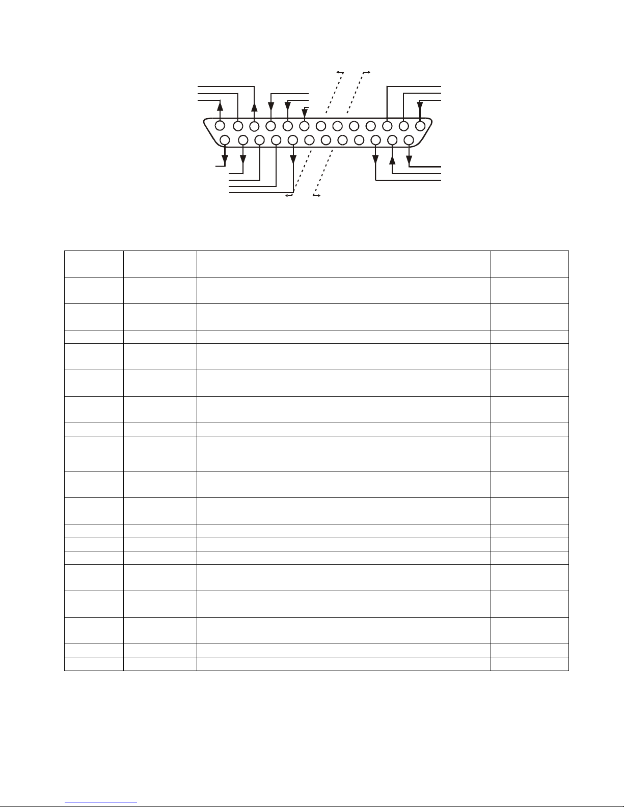
83
-
507-013 Rev. D
33
14151617181920212223242512345
67810111213
9
Same ground
as P/S negative
sense (-S)
Isolated from
PS outputs,
same ground
as RS232/RS485
IMON
IPGM_RTN
VPGM_RTN
LOC/REM SIGNAL
IF_COM
IF_COM
ENA_IN
VMON
COM
CV/CC
IPGM
VPGM
LOC/
REMPENA_OUT
SO
PS_OK
Fig. 4
-
4: J1 connector terminals and functions
Table 4
-
4: J1 connector terminals and functions
J1con
tact
Signal
name
Function
Ref
erence
J1-1
ENA_IN
Enable/Disable the power supply output by dry
-
contact
(short/open) with ENA_OUT.
Sec. 5.8
J1-2J1-3IF_COM
Isolated Interface Common. Return for the SO control,
PS_OK signal and for the optional IEEE interface.
Sec.5.7, 5.10
J1-47N/C
No Connection
J1-8
LOCAL/
REMOTE
Input for selecting between Local or Remote analog pr
o-
gramming of Output Voltage and Output Current.
Sec. 6.2
J1-9
VPGM
Input for remote analog voltage/resistance progra
m
ming
of the Output Voltage.
Sec. 6.1
6.4J1-10IPGM
Input for remote analog voltage/resistance programming
of the Output Current.
Sec. 6.1
6.4J1-11VMON
Output for monitoring the power supply Output Voltage.
Sec. 6.6
J1-12
COM
Control Common. Return for VMON, IMON, CV/CC,
LOC/REM.
Connected interna
lly to the negative sense potential (
-
S).
J1-13
CV/CC
Output for Constant
-
Voltage/Constant
-
Current mode
indication.
Sec. 5.9
J1-14
ENA_OUT
Enable/Disable the power supply output by dry
-
contact
(short/open) with ENA_IN.
Sec. 5.8
J1-15SOInput for Sh
ut-Off control of the power supply output.
Sec. 5.7
J1-16
PS_OK
Output for indication of the power supply status.
Sec. 5.10
J1-1720
N/C
No Connection.
J1-21
LOC/REM
SIGNAL
Output for indicating if the unit is in Local or Remote
analog programming mode
.
Sec. 6.3
J1-22
VPGM_RTN
Return for VPGM input. Connected internally to the “
-
S”.
Sec. 6.1, 6.4,
6.5
J1-23
IPGM_RTN
Return for IPGM input. Connected internally to the “
-
S”.
Sec. 6.1, 6.4,
6.5J1-24IMON
Output for monitoring the power supply Output Cur
rent.
Sec. 6.6
J1-25POutput for current balance in parallel operation.
Sec. 5.15
Page 42

83
-
507-013 Rev. D
34
CHAPTER 5 LOCAL OPERATION
5.1 INTRODUCTION
This Chapter describes the operating modes that are not involved in programming and monitoring the
power supply via its serial
communication port (RS232/RS485) or by remote analog signals. E
n
sure
that the REM/LOC LED on the front panel is Off, indicating Local mode. If the REM/LOC LED is On,
press the front panel REM/LOC button to change the operating mode to Local.
-
For informat
ion regarding Remote Analog Programming, refer to Chapter 6.
-
For information regarding usage of the Serial Communication Port, refer to Chapter 7.
5.2 STANDARD OPERATION
The power supply has two basic operating modes: Constant Voltage Mode and Constant C
urrent
Mode. The mode in which the power supply operates at any given time depends on the Output Vol
t-
age setting, Output Current setting and the load resistance.
5.2.1 Constant Voltage Mode
1.
In constant voltage mode, the power supply regulates the Output V
oltage at the selected value,
while the load current varies as required by the load.
2.
While the power supply operates in constant voltage mode, the VOLTAGE LED on the front panel
illuminates.
3.
Adjustment of the Output Voltage can be made when the power suppl
y output is enabled (Output
On) or disabled (Output Off). When the output is enabled, simply rotate the VOLTAGE encoder
knob to program the output voltage. When the output is disabled, press the PREV button and
then rotate the VOLTAGE encoder knob. The VO
LTAGE meter will show the programmed Output
Voltage for 5 seconds after the adjustment has been completed. Then the VOLTAGE meter will
display “OFF”.
4.
Adjustment resolution can be set to coarse or fine resolution. Press FINE button to select b
e
tween
the low
er and higher resolution. The FINE LED turns On when the resolution is set to FINE.
5.2.2 Constant Current Mode
1.
In constant current mode, the power supply regulates the Output Current at the selected value,
while the voltage varies with the loa
d requirement.
2.
While the power supply is operating in constant current mode, the CURRENT LED on the front
panel illuminates.
3.
Adjustment of the Output Current setting can be made when the power supply output is enabled
(Output On) or disabled (Output Off).
-
Disabled output (Off): Press PREV button and then rotate the Current encoder knob. The
CURRENT meter will show the programmed Output Current limit for 5 seconds after the adjus
t-
ment has been completed. Then the VOLTAGE meter will display “OFF”.
NOTE
If after completing the adjustment, the display shows a different value
than the setting, the power supply may be at current limit. Check the
load condition a
nd the power supply Output Current setting.
NOTE
The maximum and minimum setting values of the output voltage are
limited by the Over Voltage
protection and Under Voltage limit se
t
ting.
Refer to Sections 5.3 and 5.4 for more details.
Page 43

83
-
507-013 Rev. D
35
-
Enabled
output, power supply in Constant Voltage mode: Press the PREV button and then rotate
the CURRENT encoder knob. The CURRENT meter will show the programmed Output Current
for 5 seconds after the adjustment has been completed, and then will return to show the
actual
load current.
-
Enabled output, power supply in Constant Current mode: Rotate the CURRENT e
n
coder knob to
adjust the Output Current.
4.
Adjustment resolution can be set to Coarse or Fine adjustment. Press the FINE button to select
between the Coarse an
d Fine resolution. The FINE LED turns On when the resolution is set to
FINE.
5.2.3 Automatic Crossover
If the power supply operates in Constant Voltage mode, while the load current is increased to greater
than the current limit setting, the power supply wi
ll automatically switch to Constant Cu
r
rent mode. If
the load is decreased to less than the current limit setting, the power supply will automatically switch
back to Constant Voltage mode.
5.3
OVER VOLTAGE PROTECTION (OVP)
The OVP circuit protects the load in
the event of a remote or local programming error or a power su
p-
ply failure. The protection circuit monitors the voltage at the power supply sense points and thus pr
o-
vides the protection level at the load. Upon detection of an Over Voltage condition, the po
wer supply
output will shut down.
5.3.1
Setting the OVP level
The OVP can be set when the power supply output is Enabled (On) or Disabled (Off). To set the OVP
level, press the OVP/UVL button, so that the CURRENT meter shows “OUP”. The VOLTAGE meter
shows the OV
P setting level. Rotate the VOLTAGE encoder knob to adjust the OVP level. The display
will show “OUP” and the setting value for 5 seconds after the adjustment has been co
m
pleted, and
then will return to its previous state.
The minimum setting level is approximately 105% of the
set Output Voltage, or the value in Table 7
-
6, whichever is
hi
gher. The maximum setting level is shown in Table 5
-1.To preview the OVP setting, press the OVP/UVL pushbu
t-
ton so that the CURRENT display will show “OUP”. At this
time, the VOLTAGE display will show the OVP setting. A
f-
ter 5 seconds, the display will retu
rn to its previous state.
Table 5
-
1: Maximum OVP setting le
v
els
5.3.2
Activated OVP protection indications
When the OVP is activated the power supply output shuts down. The VOLTAGE display shows “OUP”
and the ALARM LED blinks.
5.3.3
R
esetting the OVP circuit
To reset the OVP circuit after it activates:
1.
Reduce the power supply Output Voltage setting below the OVP set level.
2.
Ensure that the load and the sense wiring are connected properly.
3.
There are four methods to reset the OVP circuit.
a) Press the OUT button.
b) Turn the power supply Off using the AC On/Off switch, wait until the front panel display turns
Off, then turn the power supply On using the AC On/Off switch.
c)
Turn the power supply output Off and then On using the SO control
(refer to Section 5.7). In
this method the power supply should be set to Auto
-
Restart mode.
d) Send an OUT 1command via the RS232/RS485 communication port.
Model
Max.
OVP
Model
Max.
OVP
6V8V12.5V
20V
30V
40V
50V
7.5V
10.0V
15.0V
24.0V
36.0V
44.0V
57.0V
60V
80V
100V
150V
300V
600V
66.0V
88.0V
110.0V
165.0V
330.0V
660.0V
Page 44

83
-
507-013 Rev. D
36
5.4
UNDER VOLTAGE LIMIT (UVL)
The UVL prevents adjustment of the Output Vol
t
age below a certain lim
it. The combination of UVL
and OVP functions, allow the user to create a protection window for sensitive load circuitry.
5.4.1
Setting the UVL level
Setting the UVL can be made when the power supply output is Enabled (On) or Disabled (Off). To set
the UVL level,
press the OVP/UVL button TWICE, so that the CURRENT meter shows “UUL”. The
VOLTAGE meter shows the UVL setting level. Rotate the VOLTAGE encoder knob to adjust the UVL
level. The display will show ‘UUL” and the setting value for 5 seconds after the adjust
ment has been
completed and then will return to its previous state.
UVL setting values are limited at the maximum level to approximately 95% of the Output Voltage se
t-
ting. Attempting to adjust the UVL above this limit will result in no response to the adju
stment attempt.
The minimum UVL se
t
ting is zero.
5.5
FOLDBACK PROTECTION
Foldback protection will shut down the power supply output if the load current exceeds the current
limit setting level. This protection is useful when the load circuitry is sensitive to
an overcurrent cond
i-
tion.
5.5.1
Setting the Foldback protection
To arm the Foldback protection, the FOLD button should be pressed so that the FOLD LED illum
i-
nates. In this condition, transition from Constant Voltage to Constant Current mode will activate the
Fol
dback protection. Activation of the Foldback protection disables the power supply output, causes
the ALARM LED to blink and displays “Fb” on the VOLTAGE meter.
5.5.2
Resetting activated Foldback protection
There are four methods to reset an activated Foldback pr
otection.
1.
Press the OUT button. The power supply output is enabled and the Output Voltage and Cu
r
rent
will return to their last setting. In this method, the Foldback protection remains armed, therefore if
the load current is higher than the current limit
setting, the Foldback protection will be activated
again.
2.
Press the FOLD button to cancel the Foldback protection. The power supply output will be di
s-
abled and the VOLTAGE display will show “OFF”. Press the OUT button to enable the power su
p-
ply output.
3.
Tur
n the power supply output Off and then On using the SO control (refer to Section 5.7). In this
method the Foldback protection remains armed, therefore if the load current is higher than the
output current setting, the Foldback prote
c
tion will be activated.
4.
Turn the power supply Off using the AC On/Off switch, wait until the front panel display turns Off,
then turn the unit back ON again. The power supply output is enabled and the Output Voltage and
Current will return to their last setting. In this method,
the Foldback protection remains armed,
therefore if the load current is higher than the output current setting, the Foldback protection will
be activated again.
5.6
OUTPUT ON/OFF CONTROL
The Output On/Off Enables or Disables the power supply output. Use this
function to make adjus
t-
ments to either the power supply or the load without shutting off the AC power. The Output On/Off
can be activated from the front panel using the OUT button or from the rear panel J1 connector. The
OUT button can be pressed at any ti
me to Enable or Disable the power supply output. When the ou
t-
put is disabled, the Output Voltage and Current fall to zero and the VOLTAGE display shows “OFF”.
5.7
OUTPUT SHUT
-
OFF (SO) CONTROL VIA REAR PANEL J1 CONNECTOR
Contacts 2, 3 and 15 of J1 (Fig.4
-
2, It
em 5) serve as Output Shut
-
Off (SO) terminals. The SO term
i-
nals accept a 2.5V to 15V signal or Open
-
Short contact to disable or enable the power supply output.
The SO function will be activated only when a transition from On to Off is detected after applyi
ng AC
power to the unit. (Thus, in Auto
-
Restart mode, the output will be Enabled after applying
Page 45

83
-
507-013 Rev. D
37
AC power; even if SO is at an Off level). After an On to Off transition it is detected, the SO will Enable
or Disable the power supply output according to the
signal level or the short/open applied to J1. This
function is useful for connecting power supplies in a “Daisy
-
chain” (refer to Section 5.16). The SO
control can also be used to reset the OVP and Fold Protection (refer to Section 5.3 and 5.5 for d
e-
tails)
.
When the unit is shut
-
off by a J1 signal, the VOLTAGE display will show “SO” to indicate the unit
state. J1 contact 15 is the SO signal input and contacts 2 and 3, IF_COM, are the signal return (co
n-
nected internally). Co
n
tacts 2, 3 and 15 are optically i
solated from the power supply output.
The SO control logic can be selected by the rear panel SW1 Setup switch. Refer to Table 5
-
2 for
SW1 setting and SO Control Logic.
SW1
-
5 setting
SO signal level
J1-2(3), 15
Power supply
output
Display
Down (default)
2-15V or Open
0-0.6V or Short
On
Off
Voltage/Current
“SO”
Up2-
15V or Open
0-0.6V or Short
OffOn“SO”
Voltage/Current
Table 5
-
2: SO logic selection
5.8
ENABLE/DISABLE CONTROL VIA REAR PANEL J1 CONNECTOR
Contacts 1 and 14 of J1 (Fig.4
-
2, item 5) serve
as Output Enable/Disable terminals by switch or relay. This fun
c-
tion is Enabled or Disabled by the SW1 Setup switch position 9. Refer to Table 5
-
3 for Enable/Disable function
and SW1 setting.
SW1
-
9 setting
Enable/Disable I
n
puts
Power supply ou
t
put
Display
ALARM LED
Down (Default)
Open or Short
On
Voltage/Current
Off
Open
Off
“ENA”
Blinking
Up
Short
On
Voltage/Current
Off
Table 5
-
3: Enable/Disable function and SW1 setting
5.9 CV/CC SIGNAL
CV/CC signal indicates the operating mode of the power supply
, Constant Voltage or Constant Current
.
The
CV/CC signal is an open collector output with a 30V parallel zener, at J1
-
13, referenced to the COM potential at
J1-12 (connected internally to the negative sense potential). When the power supply operates in Con
stant Vol
t-
age mode, CV/CC output is open. When the power supply operates in Constant Current mode, the CV/CC signal
output is low (0
-
0.6), with maximum 10mA sink current.
5.10 PS_OK SIGNAL
The PS_OK signal indicates the fault condition of the power suppl
y. PS_OK is a TTL signal output at J1
-
16, re
f-
erenced to IF_COM at J1
-
2, 3 (Isolated Interface Common). When a fault condition occurs, the PS_OK level is
CAUTION
To preve
nt possible damage to the unit, do not connect any of the
Enable/Disable inputs to the positive or negative output potential.
NOTE
Safe Start mode
-
If the Enable/Disable fault condition clears when units in safe start mode reco
v-
ery is by pressing OUT but
ton or by sending an ‘OUT 1’ serial command.
Auto Restart
mode
-
The
output will return back ON automatically when the Enable/Disable fault conditions clears.
CAUTION
Do not connect the CV/CC signal to a voltage source higher than 30VDC. Always
connect the CV/CC signal to voltage source with a series resi
s
tor to limit the sink
current to less than 10mA.
Page 46

83
-
507-013 Rev. D
38
low, with a maximum sink current of 1mA; when no fault condition occurs, the PS_OK level is high with
a max
i-
mum source current of 2mA. The following faults will set the PS_OK to a Fault state:
*OTP
*Enable/Disable open (Power supply is disabled)
*OVP
*SO (Rear panel Shut
-
Off, Power Supply is shut off)
*Foldback
*IEEE failure (With optional IEEE interface)
*AC fail
*Output Off
5.11 SAFE
-
START AND AUTO
-
RESTART MODES
When turning On the power supply AC On/Off, it can start to its last setting of Output Voltage and Current with
the output Enabled (Auto
-
restart mode) or start with the output Disabled (Safe
-
star
t mode). Press and hold the
OUT button to select between Safe
-
start and Auto
-
restart modes. The VOLTAGE display will continuously cycle
between “SAF” and “AU7” (“7” represents “T”) every 3 seconds. Releasing the OUT pushbutton while one of the
modes is di
s
played, selects that mode. The default setting at shipment is Safe
-
start mode.
5.11.1 Auto
-
restart mode
In this mode, the power supply restores its last operation setting. Upon start
-
up, the output is enabled
or disabled according to its last setting.
5.11
.2 Safe
-
start mode
In this mode, the power supply restores its last operation setting and sets the Output to an Off state.
At start
-
up, the output is Disabled and the Output Voltage and Current are zero. To Enable the output
and restore the last Output Vol
tage and Current values, momentarily press the OUT button.
5.12 OVER TEMPERATURE PROTECTON (OTP)
The OTP circuit shuts down the power supply before the internal components can exceed their safe
internal operating temperature. When an OTP shutdown occurs, t
he display shows “O7P” (“7” repr
e-
sents “T”) and the ALARM LED blinks.
Resetting the OTP circuit can be automatic (non
-
latched) or manual (latched) depending on the
Safe
-
start or Auto
-
restart mode.
1.
Safe
-
start mode:
In Safe
-
start mode, the power supply
stays Off after the over temperature co
n-
dition has been removed. The display continues to show “O7P” and the ALARM LED continues to
blink. To reset the OTP circuit, press the OUT button (or send an OUT ON command via the serial
port).
2.
Auto
-
restart mode:
I
n Auto
-
restart mode, the power supply recovers to its last setting automat
i-
cally when the over temperature condition is removed.
5.13 LAST SETTING MEMORY
The power supply is equipped with Last Setting Memory, which stores several power supply param
e-
ters at
each AC turn
-
off sequence.
STORED PARAMETERS:
1. OUT On or Off
2.
Output Voltage setting (PV setting)
3.
Output Current setting (PC setting)
4.
OVP level
5.
UVL level
6.
FOLD setting
7.
Start
-
up mode (Safe
-
start or Auto
-
restart)
8.
Remote/Local: If the last setting was Loca
l Lockout, (latched mode), the supply will return to R
e-
mote mode (non
-
latched).
9.
Address setting
10.
Baud rate
11.
Locked/Unlocked Front Panel (LFP/UFP)
(Items 8, 9, 10 are related to Remote Digital Control operation and are explained in Chapter 7)
12. Master/Slave
setting
Page 47
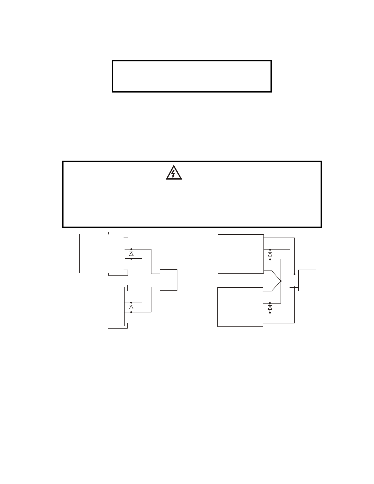
83
-
507-013 Rev. D
39
+S
+
-
-S
-LS
+LS
POWER
SUPPLY
+S
+
+
-
-
-S
-LS
+LS
POWER
SUPPLY
LOAD
+S
+
-
-S
-LS
+LS
POWER
SUPPLY
+S
+
+
-
-
-S
-LS
+LS
POWER
SUPPLY
LOAD
Fig.5-1: Series connection, local sensing
Fig.5-2: Series connection, remote sensing
(*)
(*)
(*)
(*)
(*) Diodes are
user supplied.
5.14 SERIES OPERATION
Power supplies of the SAME MODEL can be connected in series to obtain increased output voltage.
Split connection of the power supplies gives positive and negative output voltage.
5.14.1 Series connection for increased outp
ut voltage
In this mode, two units are connected so that their outputs are summed. Set the Current of each
power supply to the maximum that the load can handle without damage. It is recommended that d
i-
odes be connected in parallel with each unit output to
prevent reverse voltage during start up s
e-
quence or in case one unit shuts down. Each diode should be rated to at least the power supply rated
Output Voltage and Output Current. Refer to Fig.5
-
1 and 5
-
2 for series operation with local and r
e-
mote sensing.
Remote programming in series operation for increased output voltage:
1. Programming by external voltage:
The analog programming circuits of this power supply
are referenced to the negative output potential. Ther
e-
fore, the circuits used to contro
l each series connected
unit must be separated and floated from each other.
2. Using the SO function and PS_OK signal: The Shut
-
Off and PS_OK circuits are referenced to the
isolated interface common, IF_COM (J1
-
2,3). The
IF_COM terminals of different units
can be connected to
obtain a single control circuit for the power supplies co
n-
nected in series.
CAUTION
Do not connected power supplies from diffe
r
entmanufacturers in series or in parallel.
WARNING
When power supplies are connected in series, and the load or one of the output
terminals is grounded, no point may be at a greater potential of +/
-
60VDC from
ground for mod
els up to 60VDC Rated Output and +/
-
600VDC from ground for
models >60VDC Rated Output. When u
s
ing RS232/RS485 or IEEE, refer to the
OUTPUT TERMINALS GROUNDING warning in Section 3.9.11.
Page 48

83
-
507-013 Rev. D
40
Fig.5-3: Series connection for positive/negative output voltages
+S
+
-
-S
-LS
+LS
POWER
SUPPLY
+S
+
+
-
-
-S
-LS
+LS
POWER
SUPPLY
(*)
(*)
(*) Diodes are user supplied.
3. Programming by external resistor:
Programming by external resistor is possible. Refer to
Section 6
-
5 for details.
4. Programming via the Serial
The commu
nication port is referenced to the IF_COM
Communication port (RS232/RS485):
which is isolated from the power supply output potential.
Therefore power supplies connected in series can be
daisy
-
chained using the Remote
-
In and Remote
-
Out co
n-nec
tors. Refer
to Chapter 7 for details.
5.14.2 Series connection for positive and negative output voltage
In this mode, two units are confi
g
ured as a positive and negative output. Set the Output Current limit
of each power supply to the max
i
mum that the load can handl
e without damage. It is recommended
that diodes be connected in parallel with each unit output to prevent reverse voltage during start
-
up or
in case one of the units shuts down. Each diode should be rated to at least the power supply rated
output voltage a
nd output current. Refer to Fig.5
-
3 for this operating mode.
Remote programming in series operation for positive and negative output voltage
1. Programming by external voltage:
The analog programming circuits of this power su
p-
ply are refer
enced to the negative output potential.
Therefore, the circuits used to control each series
connected unit must be separated and floated from
each other.
2. Using the SO function and PS_OK signal:
The Shut
-
Off and PS_OK circuits are referenced to
the isol
ated interface common, IF_COM (J1
-
2,3).
The IF_COM terminals of the units can be co
n-
nected to obtain a single control circuit for the power
supplies connected in series.
3. Programming by external resistor:
Programming by external resistor is possible. Re
fer
to section 6.5 for details.
4. Programming via the Serial
Communication port (RS232/RS485):
The communication port is referenced to the
IF_COM which is isolated from the power supply
output potential. Therefore power supplies co
n-
nected in series
can be chained using the Remote
-
In and Remote
-
Out connectors. Refer to chapter 7
for details.
Page 49

83
-
507-013 Rev. D
41
5.15 PARALLEL OPERATION
Up to four units of the same VOLTAGE and CURRENT rating can be connected in parallel to provide
up to four times the Output Current ca
pability. One of the units operates as a Master and the remai
n-
ing units are Slaves. The Slave units are analog programmed by the Master unit. In remote digital o
p-
eration, only the Master unit can be programmed by the computer, while the Slave units may be
con-nected to the computer for voltage, current and status readback only. Follow the following procedure
to configure multiple supplies for parallel operation. Refer to Sec. 5.15
.1
and to Sec. 5.15.2 for d
e-
tailed explanation.
5.15.1
Basic parallel operation
In thi
s method, setting the units as Master and Slaves is made by the rear panel J1 connections and
the setup switch SW1. Each unit displays its own output current and voltage. To program the load cu
r-
rent, the Master unit should be programmed to the total load c
urrent divided by the number of units in
the system. Refer to the following procedure to configure multiple supplies for basic parallel operation.
1. Setting up the Master unit
Set the Master unit Output Voltage to the desired voltage. Program the Output C
urrent to the desired
load current divided by the number of parallel units. During operation, the Master unit operates in CV
mode, regulating the load voltage at the programmed Output Voltage. Connect the sensing circuit to
local or remote sensing as shown
in Fig.5
-
4 or fig.5
-
5.
2. Setting up the Slave units
-1.The Output Voltage of the Slave units should be programmed 2
-
5% higher than the Output
Voltage of the Master unit to prevent interference with the Master unit’s control. The Output
Current settin
g of each unit should be programmed to the desired load current divided by the
number of pa
r
allel units.
-
2. Set the rear panel setup switch SW1 position 2 to the up position.
-
3. Connect a wire jumper between J1
-
8 and J1
-
12 (refer to Table 4
-
4).-4. Conne
ct J1 terminal 10(IPGM) of the slave unit to J1 terminal 25(P) of the master unit.
During operation, the Slave units operate as a controlled current source following the Master Ou
t-
put Current. It is recommended that the power system be designed so that eac
h unit supplies up
to 95% of its current rating because of the imbalance which may be caused by cabling and co
n-
nection vol
t
age drop.
3.
Daisy Chain Connection: (See Fig. 5
-
6)
These set up
and
connections
are optional but is strongly recomm
ended. It
w
ill shut
down all power
supplies
when a
fault condition occurs in any one of them.
o
Switch SW1 position 5 should be in its down position for all power supplies.
o
Connect J1
-
16 of the Master Supply to J1
-
15 of the ‘First’ Slave Supply (If any).
o
Connect J1
-
16 of the ‘F
irst’ Slave Supply to J1
-
15 of the ‘Second’ Slave Supply (if any).
o
Connect J1
-
16 of the ‘Second’ Slave Supply to J1
-
15 of the ‘Third’ Slave Supply (If any).
o
Connect J1
-
16 of the ‘Last’ Slave Supply to J1
-
15 of the ‘Third’ Slave Supply (If any).
o
Connect J1
-
2 (or J1
-
3) common to all supplies (See Fig. 5.6).
4.
Setting Over Voltage protection
The Master unit OVP setting should be programmed to the desired OVP level. The OVP setting of
the slave units should be programmed to a higher value than the Master OVP. Whe
n the Master
unit shuts down, it programs the Slave unit to zero Output Voltage. If a Slave unit shuts down
(when its OVP is set lower than the Master Output Voltage), only that Slave unit would shut down,
and the remai
n
ing Slave units would supply all of
the load current.
5.
Setting Foldback protection
Foldback protection, is desired, may only be used with the Master unit. When the Master unit
shuts down, it programs the Slave units to zero Output Vol
t
age.
Page 50

83
-
507-013 Rev. D
42
6.
Connection to the load
In parallel operation, power
supplies can be connected in local or remote sensing. Refer to Fig. 5
-
4 and 5
-
5 for typical connections of parallel power supplies. The figures show the connection of
two units, however the same connection method applies for up to 4 units.
5.15.2
Advanced parall
el operation
In this method, multiple supplies can be configured to parallel operation as a single power supply. The
total load current and output voltage are displayed by the Master unit and can be readback from the
Master unit. The Slave units display o
nly their o
p
erating status (On, Off or Fault condition).
Refer to the following procedure to configure multiple supplies for advanced parallel operation.
1. Advanced parallel configuration
SW1 position 2
-
Down in the Master Supply and up in all Slave Supp
lies.Connect a short between J1
-
8 and J1
-
12 in all Slave Supplies.
Connect J1
-
25 of the Master Supply to J1
-
10 of all Slave Supplies.
The following set
-
up connections are optional but are strongly recommended. These se
t-
tings and connections will shut down
all the parallel power supplies when a fault condition
occurs in any one of them:
Switch SW1 position 5 should be in its down position for all power supplies (See Se
c-
tion 5.6)
Connect J1
-
16 of the Master Supply to J1
-
15 of the ‘First’ Slave Supply.
Connec
t J1-16 of the ‘First’ Slave Supply to J1
-
15 of the ‘Second’ Slave Supply (if any)
Connect J1
-
16 of the ‘Second’ Slave Supply to J1
-
15 of the ‘Third’ Slave Supply (if any)
Connect J1
-
16 of the ‘Last’ Slave Supply to J1
-
15 of the Master Supply
Connect J1
-2(or J1
-
3) common to all supplies
Select Local or Remote sense
-
Ref. Figures 5
-
4 and 5
-
5
2. Setting the units as Master or Slave
a) Depress and hold the FINE button for 3 seconds. The Master/Slave configuration will be di
s
played
on the Current Display. Ro
tate the CURRENT encoder to obtain the desired mode. Refer to Table
5-4 for the CURRENT display and modes of operation.
CURRENT Display
Operating Mode
H1
Single supply (default)
H2
Master supply with 1 Slave supply
H3
Master supply with 2 Slave supplies
H4
Master supply with 3 Slave supplies
S
Slave supply
Table 5
-
4: Setting mode of operation
b) When the desired configuration is obtained, depress and release the FINE button or wait approx. 5
seconds.
3. Master and Slave units default operation
a) When
a unit is programmed to Slave mode it enters the Remote mode with Local Lockout. In this
mode, the front panel controls are disabled to prevent accidental setting change (refer to Sec.
7.2.7 for details).
b) The Slave units parameters will automatically s
et the following:
*Output voltage to approximate. 102% of rated output voltage.
*Programmed Current to zero.
*UVL to zero volts
*OVP to its maximum value
*AST On
*OUT On
*Foldback protection Off
Page 51

83
-
507-013 Rev. D
43
c) The Master and Slave modes a
re stored in the power supply EEPROM when the AC power is turned
off. The system will return to the Ma
s
ter/Slave mode upon re
-
application of AC power.
4. CURRENT display accuracy
In the advanced parallel mode, the Master unit calculates the total current b
y multiplying the Master
output cu
r
rent by the number of Slave units. In this method, the CURRENT display accuracy is 2% +/
-1count. In cases that higher accuracy is required, it is recommended to use the basic parallel operation
mode.
5.
To release units f
rom Slave mode
Slave units can be released using the following procedure:
a) Depress FINE button for 3 seconds. The Master/Slave configuration will be displayed on the
CURRENT display.
b) Select H1 mode using the CURRENT encoder.
c) Depress FINE button aga
in or wait 5 seconds.
d) Turn the AC power Off to store the new setting.
e) After exiting from Slave operation the unit’s parameters will be set to:
*Programmed Voltage to zero
*Programmed Current to zero
*UVL to zero volts
*OVP to its maxi
mum value
*AST OFF
*OUT OFF
*Foldback protection OFF
*Locked Front Panel
Fig.5-4: Parallel connection with local sensing
MASTER
POWER SUPPLY
SLAVE#1
POWER SUPPLY
J1-25
J1-10
P
IPGM
+
V-V+V-V
LOAD
As short as possible
Twisted
pair
+S
-S
J1-8
J1-12
To J1-10
SLAVE#2
POWER SUPPLY
-S
-LS
+LS+S+LS
-LS
NOTE
With local sensing it is important to minimize the wire length and resistance. Also the positive
and negative wire resistance should be close as possible to each other to
achieve current ba
l-
ance between power su
p
plies.
CAUTION
Make sure that the connection between
–
V terminals is reliable to avoid disco
n
nection during
operation. Disconnection may cause damage to the power supply.
Page 52

83
-
507-013 Rev. D
44
5.16 DAISY
-
CHAIN CONNECTION
It is possible to configure a multiple power supply system to shut down all the units when a fault cond
i-
tion occurs in o
ne of the units. When the fault is removed, the system recovers according to its setting
to Safe
-
start or Auto
-re
start mode.
Setup switch SW1, position 5 should be set to its DOWN position to enable the Daisy
-
chain operation.
Other SW1 pos
i
tions can be set
according to the application requirements.
If a fault occurs in one of the units, its PS_OK signal will be set to a low level and the display will ind
i-
cate the fault. The other units will shut off and their display will indicate “SO”. When the fault condi
tion
is removed, the units will recover to their last setting according to their Safe
-
start or Auto
-
restart se
t-
ting.
Fig.5
-
6 shows connection of three units, however the same connection method applies to systems
with a larger number of units.
5.17 FRONT
PANEL LOCKING
The front panel controls can be locked to protect from accidental power supply parameter change.
Press and hold the PREV button to toggle between “Locked front panel’ and “Unlocked front panel”.
The display will cycle between “LFP” and “UFP”
. Releasing the PREV button while one of the modes
is displayed, s
e
lects that mode.
5.17.1 Unlocked front panel
In this mode, the front panel controls are Enabled to program and monitor the power supply param
e-
ters.
5.17.2 Locked front panel
In this mode th
e following front panel controls are Disabled:
-
VOLTAGE and CURRENT encoders.
-
FOLD button.
-
OUT button
The power supply will not respond to attempts to use these controls. The VOLT display will show
“LFP” to ind
i
cate that the front panel is locked.
OVP/ UVL button is active to preview the OVP and UVL setting.
Use the PREV button to preview the Output Vol
t
age and Current setting or to unlock the front panel.
Fig.5-6: Daisy-chain connection
POWER SUPPLY
#1J1-2,3
J1-16
J1-16
J1-16
J1-15
PS_OK
POWER SUPPLY
#2J1-2,3
J1-15
PS_OK
SO
POWER SUPPLY
#3
J1-2,3
J1-15
PS_OK
SO
SO
IF_COM
IF_COM
IF_COM
Fig.5-5: Parallel operation with Remote sensing
MASTER
POWER SUPPLY
SLAVE#1
POWER SUPPLY
J1-25
J1-10PIPGM
+
V-V+V-V+S-S
LOAD
As short as possible
Twisted
pair
+S-S+S
-S
Twisted
pair
J1-8
J1-12
To J1-10
SLAVE#2
POWER SUPPLY
+S
+LS
-LS
-S
Page 53

83
-
507-013 Rev. D
45
CAUTION
COM (J1
-
12), VPGM_RTN (J1
-
22) AND IPGM_RTN (J1
-
23) te
rminals of J1
connect internally to the
–
Sense potential (
-
S). Do not connect these term
i-
nals to any potential other than
–
Sense (
-
S), as it may damage the power
supply.
CHAPTER 6 REMOTE ANALOG PROGRAMMING
6.1 INTRODUCTION
The rear panel connector J1 allows the
user to program the power supply Output Voltage and Current
with an analog device. J1 also provides monitoring signals for Output Voltage and Output Current.
The programming range and monitoring signals range can be selected between 0
-
5V or 0
-
10V using
the setup switch SW1. When the power supply is in Remote Analog programming mode, the serial
communication port is a
c
tive and can be used to query the power supply settings.
6.2 LOCAL/REMOTE AN
ALOG INDICATION
C
ontact 8 of J1 (Fig.4
-
2, Item 5) acce
pts TTL signal or Open
-
Short contact (referenced to J1
-
12) to
select between Local or Remote Analog programming of the Output Voltage and Current.
In Local mode, the Output Voltage and Output Current can be programmed via the front panel
VOLTAGE and CURREN
T encoders or via the RS232/RS485 port. In Remote Analog mode, the Ou
t-
put Voltage and current can be programmed by analog voltage or by programming resistors via J1
contacts 9 and 10 (refer to Sections 6.4 and 6.5). Refer to Table 6
-
1 for Local/Remote Anal
og control
(J1-8) fun
c
tion and Setup switch SW1
-
1, 2 settings.
SW1
-
1, 2 se
t
tingJ1-
8 function
Output Voltage/
Current setting
Down (default)
No effect
Local
“0” or Short
Remote
Up
“1” or Open
Local
Table 6
-
1: Local/Remote Analog control function
6.3 LOCAL/REMOTE ANALOG INDICATION
Contact 21 of J1 (Fig. 4
-
2, Item 5) is an open collector output that indicates if the power supply is in
Local mode or in Remote Analog mode. To use this output, connect a pull
-
up resistor to a voltage
source of 30Vdc m
aximum. Choose the pull
-
up resistor so that the sink current will be less than 5mA
when the output is in a low state. Refer to table 6
-
2 for J1
-
21 function.
J1-8
SW1
-1SW1
-2J1-21 signal
Mode
Down
Down
Open
Local (FP)
Down
Up
00.6V
R
emote Analog
Up
Down
00.6V
Remote Analog
TTL “0” or short
UpUp00.6V
Remote Analog
TTL “1” or open
Down or Up
Down or Up
Open
Local (FP)
Table 6
-
2: Local/Remote Analog indication
Page 54
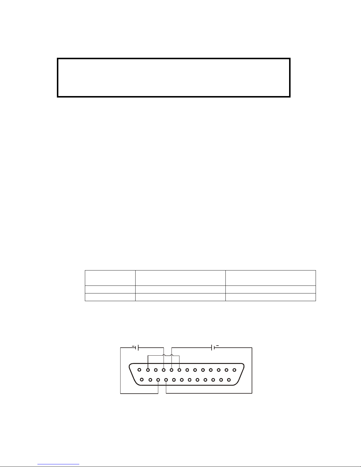
83
-
507-013 Rev. D
46
CAUTION
To maintain the power supply isolation and to prevent ground loops, use an
isolated programming source when operating the power supply via remote
analog programming at the J1 connector.
6.4 REMOTE VOLTAGE PROGRAMMING OF OUTPUT VOLTAGE AND OUTPUT
CURRENT
Per
form the following procedure to set the power supply to Remote Voltage programming:
1.
Turn the power supply AC On/Off switch to Off.
2.Set setup switch SW1, positions 1 and 2 to their UP position.
3.
Set SW1, position 3 to select the programming voltage range acc
ording to Table 6
-3.4.
Ensure that SW1, positions 7 and 8 are at their DOWN (default) position.
5.
Connect a wire jumper between J1
-
8 and J1
-
12 (refer to Table 4
-
4).6.Connect the programming source to the mating plug of J1 as shown in Fig.6
-
1. Observe
correct po
larity for the voltage source.
7.
Set the programming sources to the desired levels and turn the power supply ON. Adjust
the programming sources to change the power supply output.
NOTES:
1.
SW1, positions, 4, 5, 6 and 9 are not required for remote programming.
Their settings can
be determined according the application.
2.
The control circuits allow the user to set the Output Voltage and Output Current up to 5%
over the model
-
rated maximum value. The power supply will operate within the extended
range, however it is
not recommended to operate the power supply over its voltage and
current ra
t
ing, and performance is not guaranteed.
Table 6
-
3: SW1
-
3 setting and programming range
SW1
-
3 setting
Output Voltage progra
m
ming
VPGM (J1
-9)Output Current progra
m
ming
IPGM (J1
-10)UP0-10V0-
10V
DOWN
0-5V0-
5V
114132510128923
22
+
+
OUTPUT CURRENT
PROGRAMMING
OUTPUT VOLTAGE
PROGRAMMING
J1 connector, rear panel view
Fig.6-1: Remote voltage programming connection
Page 55

83
-
507-013 Rev. D
47
6.5 RESISITIVE PROGRAMMING OF OUTPUT VOLTAGE AND CURRENT LIMIT
For resistive programming, internal current sources, for Output Voltage and/or Output Current control,
supply 1mA current through external programmi
ng resistors connected between J1
-
9 & 22 and J1
-10& 23. The voltage across the programming resistors is used as a programming voltage for the power
supply. Resistance of 0
5Kohm or 0
10Kohm can be selected to program the Output Voltage and
Output Current
from zero to full scale.
A variable resistor can control the output over its entire range, or a combination of variable resistor
and series/parallel resistors can control the output over restricted portion of its range.
Perform the following procedure to
set the power supply to Resistive programming:
1.
Turn the AC On/Off switch to Off.
2.
Set setup switch SW1, positions 1 and 2 to their UP position.
3.
Set SW1, position 3 to select the programming resistor range according to Table 6
-4.4.
Set SW1, positions 7 and 8 t
o their UP position, to enable resistive programming mode.
5.
Connect a wire jumper between J1
-
8 and J1
-
12 (refer to Table 4
-
4).6.Connect the programming resistors to the mating plug of J1 as shown in Fig.6
-2.7.
Set the programming resistors to the desired resis
tance and turn the power supply ON. Adjust the
resistors to change the power supply output.
NOTES:
1.
SW1, positions 4, 5, 6 and 9 are not required for remote programming. Their settings can be d
e-
termined according to the application requirements.
2.
The contro
l circuits allow the user to set the Output Voltage and Output Current up to 5% over the
model
-
rated maximum value. The power supply will operate within the extended range, however it
is not recommended to operate the power supply over its voltage and curr
ent rating and perfor
m-
ance is not guaranteed.
3.
To maintain the temperature stability specification of the power supply, the resistors used for pr
o-
gramming should be stable and low noise resistors, with temperature coefficient of less than
50ppm.
4.
When resist
ive programming is used, front panel and computer control (via serial communication
port) of Output Voltage and Current are disabled.
Table 6
-
4: SW1
-
3 setting and programming range
SW1
-
3 setting
Output Voltage pr
o
gramming
VPGM (J1
-9)Output Current progr
amming
IPGM (J1
-
10)UP0-10Kohm
0-10Kohm
DOWN
0-5Kohm
0-5Kohm
114132510923
22
OUTPUT CURRENT
PROGRAMMING
OUTPUT VOLTAGE
PROGRAMMING
J1 connector, rear panel view
Fig.6-2: Remote resistive programming
PROGRAMMING
RESISTOR
PROGRAMMING
RESISTOR
OPTIONAL SETS
LOWER LIMIT
OPTIONAL SETS
LOWER LIMIT
OPTIONAL SETS
UPPER LIMIT
OPTIONAL SETS
UPPER LIMIT
12
8
Page 56

83
-
507-013 Rev. D
48
6.6 REMOTE MONITORING OF OUTPUT VOLTAGE AND CURRENT
The J1 connector, located on the rear panel provides analog signals for monitoring the Output Voltage
and Output Current. Selection o
f the voltage range between 0
-
5V or 0
-
10V is made by setup switch
SW1
-
4. The monitoring signals represent 0 to 100% of the power supply Output Voltage and Output
Current. The monitor outputs have 500 ohm series output resistance. Ensure that the sensing ci
rcuit
has an input r
e
sistance of greater than 500 Kohm or accuracy will be reduced.
Refer to Table 6
-
5 for the required J1 connection, SW1
-
4 setting and monitoring voltage range.
J1 co
n
nection
Signal
name
Signal function
Signal (+)
Return
(-)
Range
SW1
-4VMON
Vout monitor
J1-11
IMON
Iout monitor
J1-24J1-120-5V
Down
VMON
Vout monitor
J1-11
IMON
Iout monitor
J1-24J1-120-10VUpTable 6
-
5 Monitoring signals setting
Notes:
1. Radiated emissions, RCC requir
e
ments:
FCC requirements for rad
iated emissions; use a shielded
cable for the analog control signals. If using unshielded
cable, attach an EMI ferrite suppressor to the cable, as
close as possible to the power supply.
2. Front panel encoders operation:
In Remote analog mode, the output
voltage and current
can’t be set by the VOLTAGE and CURRENT encoders.
3. Front panel PREV button:
Use the PREV button to display the Output Voltage and
Current setting, as defined by the encoders or digital
commun
i
cation.
4. Communication:
In Remote ana
log mode, all power supply parameters
can be programmed and readback via the communication
port, except the Output Voltage and Current setting.
Page 57

83
-
507-013 Rev. D
49
CHAPTER 7 RS232 & RS485 REMOTE CONTROL
7.1 INTRODUCTION
This Chapter describes the operation of the Genesys
T
M
3300W power supplies via the serial comm
u-
nication port. Details of the initial set
-
up, operation via RS232 or RS485, the command set and the
communication protocol are described in this Chapter.
7.2 CONFIGURATION
7.2.1 Default setting
The power suppl
y is shipped with the following settings:
-
Address
6-Output
Off-Baud
-
rate
9600
-
Start up mode
Safe
-
start
-
RS232/485
RS232
-
OVP
Maximum
-
Vout setting
0-UVL
0-Iout setting
Maximum
-
Foldback
Off-Master/Slave
H1 (Master)
-
Front panel:
Unlocked (UFP
)
7.2.2
Address setting
The power supply address can be set to any address between 0 and 30. Follow the instructions d
e-
scribed below to set the unit address.
1.
If the unit is in Remote mode (front panel REM/LOC LED illuminated), press the REM/LOC bu
t
ton
to put th
e unit into Local mode.
2.
Press and hold for the REM/LOC button for approximately 3 sec. The VOLTAGE display will ind
i-
cate the unit address.
3.
Using the VOLTAGE adjust encoder, select the unit address.
To preview the power supply address at any time, press and
hold the REM/LOC button for approx. 3
sec. The VOLTAGE display will indicate the power supply address.
7.2.3
RS232 or RS485 selection
To select between RS232 or RS485 set the rear panel setup switch SW1
-
6 position to:
-
DOWN for RS232
-
UP for RS485
7.2.4
Baud R
ate setting
Five optional Baud rates are possible: 1200, 2400, 4800, 9600 and 19200. To select the desired rate,
the fo
l
lowing steps should be taken:
1.
If the unit is in Remote mode (front panel REM/LOC LED illuminates), press REM/LOC button to
put the unit
into Local mode.
2.
Press and hold the REM/LOC button for approximately 3 sec. The CURRENT display will show
the unit Baud Rate.
3.
Using the CURRENT adjust encoder, select the desired Baud Rate.
7.2.5
Setting the unit into Remote or Local mode
1.
The unit will be put in
to Remote mode only via serial communication command. Commands that
will put the unit into Remote mode are:
RST
PV n
OUT n
PC n
RMT n
(for n values see Tables 7
-
4, 7-5 and 7
-
6)
Page 58

83
-
507-013 Rev. D
50
NOTE
Tx and Rx are used for RS232 communication. Txd +/
-
and Rxd +/
-
are used for RS485
communication. Refer to RS
-
232 and RS
-
485 cabling and connection d
e
tails.
2.
There are two Remote modes:
1. Remote:
In this mode, return to lo
cal can be made by the front panel REM/LOC or via
serial port command RMT 0. Set the unit into Remote mode via serial port
RMT 1 command.
2. Local Lockout: In this mode the unit can be returned to Remote mode via the ser
ial port RMT 1
command or by turning off the AC power until the display turns off, and then turn
it to on again. In local Lockout mode, the front panel REM/LOC button is not a
c-
tive. Set the unit into Local Lockout mode via serial port RMT 2 co
m
mand.
7.2.6
RS
232/RS485 port in Local mode
When the power supply is in Local mode, it can receive queries or commands. If a query is received,
the power supply will reply and remain in Local mode. If a command that affects the output is r
e-
ceived, the power supply will p
erform the command and change to Remote mode.
Serial commands may be sent to set the status registers and read them while the unit is in Local
mode. If the Enable registers are set (refer to Section 7.11) the power supply will transmit SRQ’s while
in Local
.
7.2.7
Front panel in Remote mode
Front panel control in Remote mode is Disabled except for:
1. PREV: use to preview the Voltage and Current setting.
2. OVP/UVL: use to preview the OVP/UVL setting.
3.
LOC/REM: use to set the unit into Local mode.
In Local Lock
out mode, only the PREV and OVP/UVL pushbuttons are active.
7.3 REAR PANEL RS232/RS485 CONNECTOR
The RS232/RS485 interface is accessible through the rear panel RS232/RS485 IN and RS485 OUT
connectors. The connectors are 8 contact RJ
-
45. The IN and OUT co
nnectors are used to connect
power supplies in a RS232 or RS485 chain to a controller. Refer to Fig. 7
-
1 for IN/OUT conne
c
tors.
NCNCRXNCNC
TXD
RXD
TXD
RXD
RXD
TXD
RXD
TXD
SG
SG
---
-
+++
+
TX
OUT
IN
Fig.7-1: Rear panel J3 IN/OUT connectors pinout
8 7 6 5 4 3 2 1
8 7 6 5 4 3 2 1
Shield
(connector enclosure)
Page 59

83
-
507-013 Rev. D
51
7.4 MD MODE OPTION (Factory Installed)
7.4.1 MD Mode Description
The GEN supply is capable of operating in a multi drop e
nvironment
-
more than 1 supply co
n
ducting
serial communications on a single serial bus. A maximum of 31 GEN supplies can operate in this si
n-
gle bus. Upon power up the Gen will enter the point
-to-
point mode in which it is a
s
sumed that only 1
supply will op
erate on a serial bus. MD Mode must be enabled
-
Ref. Section 7.10.2.2. The user must
set all Slave supplies to a unique address. No two supplies may have the same address.
7.4.2
MD Mode enable
–
Serial communication mode
Refer to section 7.10.2.2. MD Mode is en
tered into via a Single byte command. In MD Mode the Ma
s-
ter supply shall operate in one of the two serial modes, RS232 or RS485, depending upon the rear
panel DIP switch setting and the Slave supplies shall operate in the RS485 s
e
rial mode.
7.4.3
MD Mode SRQ
In
MD Mode the SRQ generated by the supply is replaced by a single byte SRQ sent two times in s
e-
quence. The SRQ byte, in binary, will contain the address of the supply in the least significant 5 bits
with bits 5 and 6 set to logic zero and bit 7 set to logic
1. Ref. Table 7
-
4.
7.4.4
Communication Collisions
In MD Mode it is possible to have one supply issue an SRQ while another supply is transmitting
data/response to a command. When this happens, the HOST PC will receive garbled data and a
s-
sume that the data/respons
e was corrupted and thus re
-
send the command
-
the SRQ will probably
be lost. The method of recovery will be SRQ retransmission, Ref. Section 7.4.5, or pol
l
ing all attached
supplies to see who issued the SRQ
-
available by reading the SEVE? Regist
er.
7.4.5
MD Mo
de SRQ Retransmission
The supply can be commanded to retransmit the SRQ at regular intervals until it is answered to by the
HOST PC (Ref. Section 7.10.2.4). The retransmission interval is 10 ms plus the supply address mult
i-
plied by 20 ms.
Page 60

83
-
507-013 Rev. D
52
7.5 CONNECTING
POWER SUPPLIES TO RS232 OR RS485 BUS
7.5.1 Single power supply
1. Select the desired interface RS232 or RS485 using rear panel setup switch SW1
-
6 (Section 4
-
4).-RS232: DOWN position
-
RS485: UP position
2. Connect rear panel IN connector to the co
ntroller RS232 or RS485 port using a suitable shielded
cable. Refer to Figures 7
-
2, 7-3 and 7
-
4 for available RS232 and RS485 cables.
2371871
PIN NO.
PIN NO.
NAME
NAME
SHIELD
TXRXSG
SHIELD
RXTXSG
DB-25 CONNECTOR
8 PIN CONNECTOR
REMARKS
TWISTED
PAIR81
13
1
23578
1
PIN NO.
HOUSING
HOUSING
PIN NO.
NAME
NAME
SHIELD
RXTXSG
SHIELD
TXRXSG
DB-9 CONNECTOR
8 PIN CONNECTOR
REMARKS
TWISTED
PAIR
815
1
981546315
4
PIN NO.
HOUSING
HOUSING
PIN NO.
NAME
NAME
TWISTED
PAIR
TWISTED
PAIR
SHIELD
TXD
TXDSGRXD
RXD
SHIELD
RXD
RXDSGTXD
TXD
DB-9CONNECTOR
8 PINCONNECTOR
REMARKS
-
+++
+
---
815
1
Fig.7-2: RS232 cable with DB25 connector (P/N: GEN/232-25)
Fig.7-3: RS232 cable with DB9 connector (P/N: GEN/232-9)
Fig.7-4: RS485 cable with DB9 connector (P/N: GEN/485-9)
L=2mtyp.
L=2mtyp.
L=2mtyp.
Sockets
Sockets
Sockets
Page 61

83
-
507-013 Rev. D
53
NOTE
The address (ADR n) command must return an “OK” response b
e
fore any
other comman
ds are accepted.
7.5.2
Multi power supply co
n
nection to RS232 or RS485 bus
Up to 31 units can be connected (daisy chained) to the RS232 or RS
485 bus. The first unit connects
to the co
n
troller via RS232 or RS485 and the other units are connected via the RS485 bus.
1. First unit connection: Refer to Section 7.5.1 for connecting the first unit to the controller.
2. Other units connection: The o
ther units on the bus are connected via their RS485 interface.
Refer to Figure 7
-
5 for typical connection.
-
Set rear panel setup switch SW1
-
6 to its UP position.
-
Using the Linking cable supplied with each unit (refer to Fig. 7
-
6), connect
each unit OUT
conne
c
tor to the next unit IN connector.
7.6 COMMUNICATION INTERFACE PROTOCOL
7.6.1 Data format
Serial data format is 8 bit, one start bit and one stop bit. No parity bit.
7.6.2
Addressing
The Address is sent separately from th
e command. It is recommended to add 100msec delay b
e-
tween query or sent command to next unit addressing. Refer to Section 7.8.3 for d
e
tails.
7.6.3
End of Message
The end of message is the Carriage Return character (ASCII 13). The power supply ignores the Line
Fe
ed (ASCII 10) character.
7.6.4
Command Repeat
The backslash character “
\
” will cause the last command to be repeated.
7.6.5
Checksum
The user may add a checksum (optional) to the end of the command. The checksum is “$” followed
by two hex characters. If a command or a
query has a checksum, the response will also have one.
There is no CR between the command string and the “$” sign.
Example: STT?3A
STAT?$7B
7.6.6
Acknowledge
The power supply acknowledges received commands by returning an “OK” message. If an e
rror is
detected the power supply will return an error message. The rules of checksum also apply to the a
c-
know
l
edge.
IN
OUT
POWER SUPPLY
#1
IN
OUT
POWER SUPPLY
#2
IN
OUT
POWER SUPPLY
#3
IN
OUT
POWER SUPPLY
#31
RS232/RS485
RS485
RS485
RS485
Fig7-5: Multiple power supply RS232/485 connection
811
8
163541635
4
PIN NO.
HOUSING
HOUSING
PIN NO.
NAME
NAME
SHIELD
SG
TXD
TXD
RXD
RXD
SHIELD
SG
RXD
RXD
TXD
TXD
-
+++
+
---
Serial link cable with RJ-45 shielded connectors (P/N: GEN/RJ-45)
Fig.7-6:
L=0.5m typ.
Page 62

83
-
507-013 Rev. D
54
7.6.7
Error message
If an error is detected in command or query, the power supply will respond with an error message.
Refer to Section 7.7 for
details.
7.6.8
Backspace
The backspace character (ASCII 8) clears the last character sent to the power supply.
7.7 ERROR MESSAGES
The power supply will return error messages for illegal commands and illegal programming param
e-
ters. Refer to Table 7
-
1 for program
ming error messages and Table 7
-
2 for command error me
s-
sages.
Table 7
-
1: Programming error messages
Error
Code
Description
E01
Returned when program voltage (PV) is programmed above acceptable range.
Example: PV above ‘105% of supply rating’ or PV above 9
5% of OVP setting’.
E02
Returned when programming output voltage below UVL setting.
E04
Returned when OVP is programmed below acceptable range.
Example: OVP less than “5% of supply voltage rating’ plus ‘voltage setting’.
E06
Returned when UVL is program
med above the programmed output voltage.
E07
Returned when programming the Output to ON during a fault shut down.
Table 7
-
2: Commands error messages
Error
Code
Description
C01
Illegal command or query
C02
Missing parameter
C03
Illegal parameter
C04
C
hecksum error
C05
Setting out of range
7.8 COMMAND SET DESCRIPTION
7.8.1 General guide
1.
Any command or argument may be in capital letters or small letters.
2.
In commands with an argument, a space must be between the command and the arg
u
ment.
3.
For any com
mand that sets a numeric value, the value may be up to 12 characters long.
4.
Carriage Return: If the CR character (ASCII 13) is received by itself, the power supply will r
e
spond
with “OK” and CR.
7.8.2
Command set categories
1.
Initialization control
2.
ID control
3.
Outpu
t control
4.
Status control
Page 63

83
-
507-013 Rev. D
55
7.8.3
Initialization Control Commands
#
Command
Description
1
ADR n
ADR is followed by address, which can be 0 to 30 and is used to access the
power supply.
2
CLS
Clear status. Sets FEVE and SEVE registers to zero (refer to Sectio
n 7-11).3RST
Reset command. Brings the power supply to a safe and known state:
Output voltage: zero, Remote: non
-
lockout remote,
Output current: zero, Auto
-
start: Off,
Output: Off, OVP: maximum,
FOLD: Off,
UVL: zero
The conditional registers (FLT and STAT) are updated, the other registers are
not changed.
4
RMT
Sets the power supply to local or remote mode:
1.
RMT 0 or RMT LOC, sets the power supply into Local mode.
2.
RMT 1 or RMT REM, sets the unit into remot
e mode.
3.
RMT 2 or RMT LLO, sets the unit into Local Lockout mode (latched r
e
mote mode).
5
RMT?
Returns to the Remote mode setting:
1.
“LOC”
-
The unit is in Local mode.
2.
“REM”
-
The unit is in Remote mode.
3.
“LLO”
-
The unit is in Local Lockout (latched remote)
mode.
6
MDAV?
Returns MD MODE OPTION Status. 1 indicates installed and 0 indicates not i
n-
stalled.
7
\
Repeat last command. If
\
<CR> is received, the power supply will repeat the last
command.
7.8.4
ID Control Commands
#
Command
Description
1
IDN?
Returns the
power supply model identification as an ASCII string:
LAMBDA, GENX
-
Y
2
REV?
Returns the software version as an ASCII string.
3
SN?
Returns the unit serial number. Up to 12 characters.
4
DATE?
Returns date of last test. Date format: yyyy/mm/dd
7.8.5
Output Co
ntrol Commands
#
Command
Description
1
PV n
Sets the output voltage value in Volts. The range of voltage value is described in
Table 7
-
5. The maximum number of characters is 12. See the following exa
m
ples
for PV n format: PV 12, PV 012, PV 12.0, PV 012.00
, etc…
2
PV?
Reads the output voltage setting. Returns the string “n” where “n” is the exact
string sent in the PV n command. When in Local mode, returns the PREVIEW
(front panel) settings in a 5 digit string.
3
MV?
Reads the actual output voltage. Retur
ns a 5 digits string.
Example: 60V supply sends 01.150, 15.012, 50.000, etc…
4
PC n
(See
Note 1)
Set the Output Current value in Amperes. The range of current values is d
e-
scribed in Table 7.6. The maximum number of characters is 12. See the following
exa
mples for PC n format: PC n format: PC 10, PC 10.0, PC 010.00, etc…
5
PC?
Reads the Output Current setting. Returns the string “n” where “n” is the exact
string sent in the PC n command. When in Local mode, returns the PREVIEW
(front panel) se
t
tings in a
5 digit string.
6
MC? (See
Note 2)
Reads the actual Output Current. Returns a 5 digit string.
Example: 200A supply sends 000.50, 110.12, 200.00, etc…
Page 64

83
-
507-013 Rev. D
56
#
Command
Description
7
DVC?
Display Voltage and Current data. Data will be returned as a string of ASC
II
characters. A comma will separate the different fields. The fields, in order, are:
Measured Voltage, Programmed Voltage, Measured Current, Programmed Cu
r-
rent, Over Voltage Set Point and Under Voltage Set Point.
Example: 5.9999,6.0000,010.02,010.00,7.500
,0.000
8
FILTER
nn
Set the low pass filter frequency of the A to D Converter for Voltage and Current
Measurement where nn = 18, 23 or 46.
9
FILTER?
Returns the A to D Converter filter frequency: 18,23 or 46 Hz.
10
OUT n
Turns the output to ON or OFF. Re
cover from Safe
-
Start, OVP or FLD fault.
OUT 1 (or OUT ON)
-
Turn On.
OUT 0 (or OUT OFF)
-
Turn Off
11
OUT?
Returns the output On/Off status string.
ON-output On. OFF
-
output Off.
12
FLD n
Sets the Foldback protection to ON or OFF.
FLD 1 (or FOLD ON)
-
Arms the Foldback protection
FLD 0 (or FOLD OFF)
-
Cancels the Foldback protection.
When the Foldback protection has been activated, OUT 1 command will release
the pr
o
tection and re
-
arm it, while FLD 0 will cancel the protection.
13
FLD?
Returns the Fo
ldback protection status string:
“ON”
-
Foldback is armed. “OFF”
-
Foldback is cancelled.
14
FBD nn
Add (nn x 0.1) seconds to the Fold Back Delay. This delay is in addition to the
standard delay. The range of nn is 0 to 255. The value is stored in epr
om at AC
power down and recovered at AC power up.
15
FBD ?
Supply returns the value of the added Fold Back Delay.
16
FBDRST
Reset the added Fold Back Delay to zero.
17
OVP n
Sets the OVP level. The OVP setting range is given in Table 7
-
7. The number of
characters after OVP is up to 12. The minimum setting level is approximately
105% of the Output Voltage setting, or the value in Table 7
-
7, whichever is
higher. The maximum OVP setting level is shown in Table 5
-
1. Attempting to
program the OVP below this l
evel will result in an execution error response
(“E04”). The OVP setting stays u
n
changed.
18
OVP?
Returns the setting “n” where “n” is the exact string in the user’s “OVP n”. When
in Local mode, returns the last setting from the front panel in a 4 digit s
tring.
19
OVM
Sets OVP level to the maximum level. Refer to Table 7
-7.20
UVL n
Sets Under Voltage Limit. Value of “n” may be equal to PV setting, but returns
“E06” if higher. Refer to Table 7
-
8 for UVL programming range.
21
UVL?
Returns the setting “n”
where “n” is the exact string in the user’s “UVL n”. When
in Local mode, returns the last setting from the front panel in a 4 digit string.
22
AST n
Sets the Auto
-
restart mode to ON or OFF.
AST 1 (or AST ON): Auto restart On.
AST 0 (or AST OFF): Auto res
tart Off.
23
AST?
Returns the string auto
-
restart mode status.
24
SAV
Saves present settings. The settings are the same as power
-
down last setting.
These se
t
tings are erased when the supply power is switched Off and the new
“last settings” are saved.
25
RCL
Recalls last settings. Settings are from the last power
-
down or from the last
“SAV” command.
Page 65

83
-
507-013 Rev. D
57
26
MODE?
Returns the power supply operation mode. When the power supply is On (OUT
1) it will return “CV” or “CC”. When the power supply is OFF (OUT 0 or
fault
shutdown) it will r
e
turn “OFF”.
27
MS?
Returns the Master/Slave setting. Master: n= 1, 2, 3, or 4 Slave: n=0
NOTES:
1. In Advanced parallel mode (refer to Sec. 5.15.2), “n” is the total system current.
2. In Advanced parallel mode, “MC?” returns
the Master unit current multiplied by the number of slave
units +1.
7.9 GLOBAL OUTPUT COMMANDS
7.9.1
General
All supplies, even if not the currently addressed supply, receiving a global command will execute the
command. No response to the PC issuing the comman
d will be returned to the PC. The PC iss
u
ing
the command will be responsible to delay and any other communications until the command is ex
e-
cute. 200 Ms minimum is the suggested delay.
If the command contains an error, out of range values for example, no er
ror report will be sent to the
issuing PC.
GRST
Reset. Brings the power supply to a safe and known state:
Output voltage: 0V, output current: 0A, OUT: Off, Remote: RMT 1,
AST: Off OVP: Max, UVL:
0.
The conditional register (FLT and STAT) are updated. Other registers are
not
changed.
Non
-
Latching faults (FB, OVP, SO) are cleared, OUT fault stays
GPV n
Sets the output voltage value in volts. The range of voltage values is shown in T
a-
ble 7
-
5. ‘n’ m
ay be up to 12 char plus dec. pt
GPC n
Program the output current value in amperes. The range of current values is
shown in Table 7
-
6. ‘n’ may be up to 12 characters plus decimal pt
GOUT
Turns the output to ON or OFF:
“OUT 1/ON” = turn on
“OUT 0/OFF” = t
urnoff, clears CV and CC bits in the Status Condition (STAT).
OUT ON will respond with “E07’ if the output cannot be turned on because of a
latching fault (OTP< AC, ENA, SO) shutdown.
GSAV
Save present settings. Same settings as power
-
down last settings
listed in E
r
ror!
Reference source not found. Except the address and Baud rate are not saved
Saves to the RAM. These settings are erased when the supply power is switched
off and the new ‘last settings’ are saved.
GRCL
Recall last settings. Settings are fr
om last power
-
down or from last ‘SAV’ or
‘GSAV’ command. Address and Baud rate are not recalled so communication is
not interrupted.
Page 66

83
-
507-013 Rev. D
58
7.10 SINGLE BYTE COMMANDS
7.10.1
General
Single byte commands are commands in which all the necessary data for the supply to
act upon is
contained in a single byte. Single byte commands will be executed immediately by the supply. If the
command requires data to be sent to the HOST PC or IEEE Board (see sections 7.10.4 and 7.10.3.1)
that response will be transmitted immediately
with no delay due to any software overhead. With the
exce
p
tion of the Disconnect from communications command, section 7.10.3.1, commands must be
sent by the HOST PC or IEEE Board 2 times in sequence for verif
i
cation. All have the most significant
bit, D7,
set to a logic 1. A CR, carriage return, character is not included in a single byte command.
The RST command will not change any setting made by a single byte command.
All Single Byte commands will be executed in 1 ms or less. This does not include any res
ponse sent
to the HOST/IEEE Board, which is dependent upon the response length and the serial transmission
speed (Baud rate).
7.10.2
Global commands without response
7.10.2.1
Disable MD Mode (MD MODE OPTION REQUIRED)
Disable is the default condition upon power up. The Hex
value of the command is 0xA0. Send it two
times in sequence. All supplies, both the currently addressed supply and all non
-
addressed su
p
plies,
will disable MD Mode as a result of this command.
7.10.2.2
Enable MD Mode (MD MODE OPTION REQUIRED)
Send to enable Multi
Drop Mode. The Hex value of the command is 0xA1. Sent it two times in s
e-
quence. When this command is sent, the supply will set SRQ retransmission to the disable state; if
you wish it to be enabled you must send the enable command. All supplies, both the cu
rrently a
d-
dressed supply and all non
-
addressed supplies, will enable MD Mode as a r
e
sult of this command.
7.10.2.3
Disable SRQ retransmission (MD MODE OPTION REQUIRED)
Disable is the default condition upon power up. The Hex value of the command is 0xA2. Sent
it two
times in sequence. If the supply sends an SRQ it will only sent it 1 time. All supplies, both the cu
r-
rently addressed supply and all non
-
addressed supplies, will disable SRQ retransmission as a result
of this command. All status registers will retain thei
r data when this command is sent.
7.10.2.4
Enable SRQ retransmission (MD MODE OPTION REQUIRED)
Enable retransmission of SRQs. This is only available when the Multi Drop Mode is enabled in the
supply. The Hex value of the command is 0xA3. Send it two times in sequen
ce. If the supply sends an
SRQ it will be repeated on a timely basis, 10 ms plus 20 ms times the supply address, until answered.
All supplies, both the currently addressed supply and all non
-
addressed supplies, will enable SRQ r
e-
transmission as a result of
this co
m
mand.
7.10.2.5
Enable FLT Bit in the SENA Register
The Hex value of the command is 0xA4. Send it two times in sequence.
7.10.3
Global commands with response
7.10.3.1
Disconnect from communications
Command the supply to end all data transmissions to the HOST PC/IEEE Board
and cease its role as
the active addressed supply. The HOST PC/IEEE Board will be required to re
-
send the ‘ADR nn’ co
m-
mand to reestablish communications with the supply. After receiving the first command the supply will
respond with an OK<CR>. The Hex val
ue of the command is 0xBF. All supplies, both the currently
addressed supply and all non
-
addressed supplies, will
respond to this command; but only the cu
r-
rently a
d
dressed supply (if any) will respond with the ‘OK’.
Page 67

83
-
507-013 Rev. D
59
7.10.4
Addressed commands with response
7.10.4.1
Read
registers
Send (0x80 + Address) (1 byte binary
-
send 2 times sequentially). The supply will return the contents
of the Status Condition Register, the Status Enable Register, the Status Event Re
g
ister (SEVE?), the
Fault Condition Register, the Fault Enabl
e Register and the Fault Event Register IFEVE/). All registers
will be represented in two Hex bytes. Following the register data, a single dollar sign, $, will be added
to signal the end of data and the start of a chec
k
sum. The checksum will be the sum of
all register
data and will be represented in two Hex bytes. The transmission will end with the CR character. If r
e-
petitive sending of SRQs was active and the supply was sending them, the supply will stop sen
d
ing
repetitive SRQs but leave the function activ
e. The contents of the registers will not be destroyed. Note
that the supply does snot have to be the active addressed su
p
ply.
Note that this command will not execute if another command is being processed.
7.10.4.2
Print Power On Time
Print the total time the suppl
y has operated under AC power. Send 2 bytes in sequence, A6 Hex and
the address of the supply in binary. A 32 bit integer will be returned in 8 Hex bytes. The data will be
the number of minutes that power has been ‘ON’ in the supply in binary. A ‘$’ sign a
nd 2 byte Hex
checksum will be appended to the data. There is no method provided to reset this number.
Retransmit last message.
Send (0xC0 + Address) (1 byte binary
-
send 2 times sequentially). The supply will return the last
message sent. Note that the s
upply does not have to be the active addressed su
p
ply.
This command will not execute if another command is being processed.
Note that Single byte commands do not load data into the supply’s data output buffer.
Thus this command will not cause the supply to
retransmit data obtained from any previous Single
Byte Command.
7.10.4.3
Retransmit Last Message
Send (0xC0 + Address) (1 byte binary
-
send 2 times sequentially). The supply will return the last
message sent. Note that the supply does not have to be the active ad
dressed su
p
ply.
This command will not execute if another command is being processed.
Note that Single byte commands do not load data into the supply’s data output buffer. Thus this co
m-
mand will not cause the supply to retransmit data obtained from any prev
ious Single
Byte Command.
7.10.4.4
Test if MD Mode is Installed
Send AA Hex followed by the address of the supply in binary. If not installed, the supply will return a
‘1’. If installed, the supply will return a ‘0’.
7.10.5
Addressed commands without response
7.10.5.1
Acknowledge
SRQ
Send (0xE0 + Address) (1 byte binary
-
send 2 times sequentially). The supply will stop re
-
sending
SRQ. If Enable SRQ retransmission is active, it will remain active.
7.10.5.2
Re-enable SRQ with out reading/clearing the SEVE Register
Send A5 Hex followed by the
address of the supply in binary and new SRQ’s generated by new
events in the Fault Event will be enabled without reading and clearing the Status Event Register. All
events previously recorded in the Fault Event Register must have been serviced by the user
’s sof
t-
ware prior to this command to take affect.
Page 68

83
-
507-013 Rev. D
60
Table 7
-
3. SINGLE BYTE COMMUNICATIONS
Name
Bit Positions
Response
Description
Global
Commands
Disable MD Mode
1010 0000
None
Set supplies out of MD Mode (d
e
fault)
Enable MD Mode
1010 0001
None
Set supplies into MD Mode
Disable SRQ
retransmission
1010 0010
None
Disable retransmission of SRQs by
supplies (default)
Enable SRQ
retransmission
1010 0011
None
Enable retransmission of SRQs by
supplies
Enable FLT Bit
1010 0100
None
Enable th
e FLT bit in the SENA Re
g-
ister
Disconnect serial
communications
1011 1111
OK
All supplies will halt transmission and
enter the non
-
addressed state.
Addressed
Commands
Read Registers
100x xxxx
Register data
Non destructive read of all register. x
xxxx is the address of the supply in
binary.
Re-enable SRQ
Byte 1
1010 0101
Byte 2
xxxx xxxx
None
Re-enable SRQ without reading or
clearing the SEVE Register. xxxx xxxx
is the address of the supply in binary.
Works only in MD Mode.
Print Power On
T
ime
Byte 1
1010 0110
Byte 2
xxxx xxxx
Power On time
in minutes
Read the time the supply is active u
n-
der AC Power. xxxx xxxx is the a
d-
dress of the supply in binary. Returns a
32 Bit integer as 8 Hex bytes. A ‘$’
sign is appended to the data followed
by a 2
byte check
-
sum. A total of 11
bytes are returned.
Retransmit last
message
110x xxxx
Last message
Retransmit last response from a co
m-
mand. x xxxx is the address of the
supply in binary.
Acknowledge
SRQ
111x xxxx
None
Acknowledge SRQ. If retransmission
of
SRQ is enabled, it will remain e
n-
abled for the next SRQ. X xxxx is the
address of the supply in binary.
Test if MD Mode
is Installed
Byte 1
1010 1010
Byte 2
xxxx xxxx
0 or 1
Returns a 0 if not installed or a 1 if i
n-
stalled. A ‘$’ sign followed by a 2 byte
s
checksum and Carriage Return is a
p-
pended to the data. xxxx xxxx is the
address of the supply in binary.
Supply Initiated
Communications
SRQ
100x xxxx
N/A
SRQ from supply when in MD Mode. X
xxxx is the address of the supply in
binary.
Page 69

83
-
507-013 Rev. D
61
GEN750W model
s
GEN1500W models
Table 7
-
4: Current programming range
Table 7
-
5: Current programming range
Model
Minimum
(A)
Maximum
(A)
Model
Minimum
(A)
Maximum
(A)
GEN6
-
100
000.00
100.00
GEN6
-
200
000.00
200.00
GEN8
-90
00.00
90.00
GEN8
-
180
000.00
180.00
GEN12.5
-6000.000
60.000
GEN12.5
-
120
000.00
120.00
GEN20
-3800.000
38.000
GEN20
-7600.00
76.00
GEN30
-2500.000
25.000
GEN30
-5000.000
50.000
GEN40
-1900.000
19.000
GEN40
-3800.000
38.000
GEN60
-
12.5
00.000
12.500GEN60
-2500.000
25.000
GEN80
-
9.5
0.000
9.500
GEN80
-1900.000
19.000
GEN100
-
7.5
0.000
7.500
GEN100
-1500.000
15.000
GEN150
-50.000
5.000
GEN150
-1000.000
10.000
GEN300
-
2.5
0.000
2.500
GEN300
-50.000
5.000
GEN600
-
1.3
0.000
1.300
GEN600
-
2.6
0.0002.600
NOTE:
The power supply can accept values higher 5% than the table values, however it is not recommended to
program the power supply over the rated values.
Table 7
-
6: OVP programming range
Table 7
-
7: UVL programming range
Model
Rated Output Vol
t
age (V)
Minimum
(V)
Maximum
(V)
Model
Rated Output Voltage (V)
Minimum
(V)
Maximum
(V)
6
0.5
7.5060
5.70
8
0.5
10.080
7.60
12.5
1.0
15.0
12.5011.9201.0
24.0200
19.0302.0
36.0300
28.5402.0
44.0400
38.0605.0
66.0600
57.0805.0
88.0800
76.0
100
5.0
110.0
100095.0
150
5.0
165.0
1500142
300
5.0
330.0
3000285
600
5.0
660.0
6000570
Page 70

83
-
507-013 Rev. D
62
7.10.6
Status Control Commands
Refer to Section 7
-
8 for definition of the registers.
#Command
Description
1
STT?
Reads the complete power supply status.
Returns ASCII characters representing the following data, separated by commas:
MV<actual (measured) voltage> PC<programmed (set) current>
PV<programmed (set) voltage>
SR<status register, 2
-
digit hex>
MC<actual (measured) current> FR<fault register, 2
-
digit hex>
Example response: MV(45.201),PV(45), MC(4.3257), PC(10), SR(30), FR(00)
2
FLT?
Reads Fault Conditional Register. Returns 2
-
digit hex.
3
FENA
Set Fault Enable Register using 2
-
digit hex.
4
FENA?
Reads Fault Enable Register. Returns 2
-
digit hex.
5
FEVE?
Reads Fault Event Register. Returns 2
-
digit hex. Clears bits of Fault Event Register.
6
STAT?
Reads Status Conditional Register. Retur
ns 2
-
digit hex.
7
SENA
Sets Status Enable Register using 2
-
digit hex.
8
SENA?
Reads Status Enable Register. Returns 2
-
digit hex.
9
SEVE?
Reads Status Event register. Returns 2
-
digit hex. Clears bits of Status Event register.
7.11 STATUS, ERROR AND SR
Q REGISTERS
7.11.1 General Description
This Section describes the various status error and SRQ registers structure. The registers can be
read or set via the RS232/RS485 commands. When using the IEEE option, refer to the User’s Manual
for Gen
e
sysTMPower Su
pply IEEE Programming Interface.
Refer to Fig. 7
-
7 for the Status and Error Registers Diagram.
Page 71
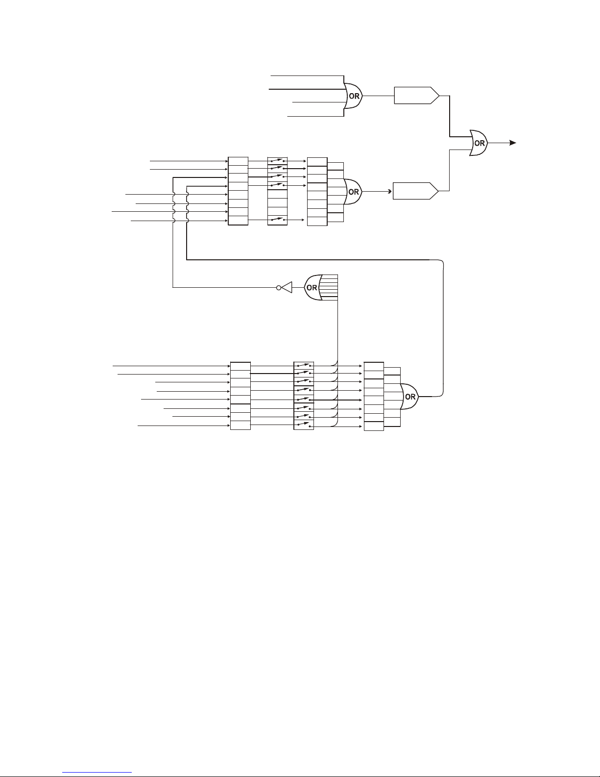
83
-
507-013 Rev. D
63
SRQ
Messages
Response
messages
Command Error (”Cnn”)
ExecutionError (”Enn”)
Query Response (”message”)
Command Response (”OK”)
CV
CC
NFLT
FLT
AST
FDE0LCLCVCC
NFLT
FLT000LCL00
0
Status Registers
Condition
Enable
Event
ConstantVoltage
ConstantCurrent
No Fault
Fault
Auto Start
Fold Enabled
Spare
Local Mode
0
1234567
“STAT?”
“SENA xx”
“SENA?”
“SEVE?”
0ACOTP
FLD
OVPSOOFF
ENA
Fault Registers
Condition
Enable
Spare
AC Fail
Over Temperature
Foldback(tripped)
Over Volt Prot
Shut Off (rear panel)
OutputOff (front panel)
EnableOpen
012
34567
“FLT?”
“FENA xx”
“FENA?”
0ACOTP
FLD
OVPSOOFF
ENA
Event
“FEVE?”
MSB
MSB
LSB
Serial
TXD
LSB
One response for every command
or query received.
One SRQ when SEVE goes
from all zeroes to any bit set.
Setting more SEVE bits does
notcausemoreSRQs.
PositiveLogic:
0 = No Event
1 = Event Occured
Fig.7-7: Status and Error Registers Diagram
“Inn” and CR
7.11.2 Conditional Registers
The fault Condition Register and the Status Condition Register are read only registers that th
e user
may read to see the condition of the Power supply. Refer to Table 7
-
8 for description of the Fault
Cond
i
tion Register bits and Table 7
-
9 for the Status Condition register bits.
Page 72

83
-
507-013 Rev. D
64
7.11.2 Conditional Registers (continued)
Table 7
-
8: Fault Condit
ion Register
BIT
Fault name
Fault symbol
Bit Set condition
Bit Reset condition
0 (LSB)
Spare bit
SPARE
Fixed to zero
Fixed to zero
1
AC Fail
AC
AC fail has occurred.
The AC input returns to normal.
2
Over
temper
a
ture
OTP
OTP shutdown has
occurre
d.
The power supply cools down.
3
Foldback
FOLD
Foldback shutdown
has occurred
The supply output is turned On by front
panel button or OUT 1 command.
4
Over vol
t
age
OVP
OVP shutdown has
occurred.
The supply output is turned ON by front
panel button or OU
T 1 command.
5
Shut Off
SO
Rear panel J1 “Shut
Off” condition has o
c-
curred.
Rear panel J1 “Shut Off” condition has
been r
e
moved.
6
Output Off
OFF
Front panel OUT bu
t-
ton pressed to Off.
The supply output is turned On by front
panel button or OUT 1 command
.
7(MSB)
Enable
ENA
Rear panel J1 Enable
terminal (J1
-
1&J1
-
14)
opened.
Rear panel J1 Enable terminals closed.
Table 7
-
9: Status Condition Register
BIT
Fault name
Fault symbol
Bit Set condition
Bit Reset condition
0 (LSB)
Constant
Voltage
CV
Output is On
and the
supply in CV.
Output is ON and the supply is not in
CV.1Constant
Current
CC
Output is ON and the
supply in CC.
Output is ON and the supply is not in
CC.2No Fault
NFLT
The power supply is
operating normally or
fault reporting is not
enabled.
See “OUT n” co
m-
mand in Section 7.7.5.
One or more faults are active and fault
reporting is enabled (using “FENAxx”).
3
Fault active
FLT
One or more faults are
enabled and occur.
Fault Event Register cleared (FEVE?).
4
Auto
-
Restart
Enabled
AST
Supply is
in Auto
-
Restart mode (from
Front Panel or serial
command).
Supply is in Safe
-
Start mode (from
Front Panel or serial command).
5
FoldEn
abled
FDE
Fold protection is
enabled (from Front
Panel or serial
command).
Fold protection disabled (fr
om Front
Panel or serial command).
6
Spare bit
SPARE
Fixed to zero.
Fixed to zero.
7(MSB)
Local Mode
LCL
Supply in Local mode.
Supply in Remote mode or Local
-
Lockout mode.
7.11.3
Service Request: Enable and Event Registers
The conditional Registers are contin
uously monitored. When a change is detected in a register bit
which is enabled, the power supply will generate an SRQ message.
The SRQ message is: “Inn” terminated by CR, where the nn is the power supply address. The SRQ
will be generated either in Local o
r Remote mode.
Page 73

83
-
507-013 Rev. D
65
Refer to Tables 7
-
10 to 7
-
13 for details of the Enable and Event registers.
1.
Fault Enable Register
The Fault Enable Register is set to the enable faults SRQs.
Table 7
-
10: Fault Enable Register
BIT
Enable
bit name
Fault symbol
Bit Set condi
tion
Bit reset condition
0 (LSB)
Spare bit
SPARE
1
AC Fail
AC2Over Temperature
OTP
3
Foldback
FOLD
4
Over Voltage
OVP
5
Shut Off
SO6Output Off
OFF
7(MSB)
Enable
ENA
User command:
“FENA nn” where
nn is hexadecimal
User command: “FENA nn”
where nn is hexadecimal (if
nn=”00”, no fault SRQs will
be generated).
2.
Fault Event Register
The Fault Event will set a bit if a condition occurs and it is Enabled. The register is cleared when
FEVE?, CLS or RST commands are received.
Table 7
-
11: Fault Event Register
BIT
Enable
bit name
Fault symbol
Bit Set condition
Bit reset condition
0 (LSB)
Spare bit
SPARE
1
AC Fail
AC2Over Temperature
OTP
3
Foldback
FOLD
4
Over Voltage
OVP5
Shut Off
SO6Output Off
OFF
7(MSB)
Enable
ENA
Fault condition
occurs and it is
enabled.
The fault can set a
bit, but when the
fault clears the bit
remains set.
Entire Event Re
gister is
cleared when user sends
“FEVE?” command to read
the register.
“CLS” and power
-
up also
clear the Fault Event Regi
s-
ter. (The Fault Event Regi
s-
ter is not cleared by RST)
Page 74

83
-
507-013 Rev. D
66
3.
Status Enable Register
The Status Enable Register is set by the user to Enable SRQs for changes in power supply status.
Table 7
-
12: Status Enable Register
BIT
Status name
Status sy
m
bol
Bit
Set cond
i
tion
Bit reset condition
0 (LSB)
Constant Voltage
CV
1
Constant Current
CC2No Fault
NFLT
3
Fault active
FLT
User command:
“SENA nn” is
received, where
nn is hexadec
i
mal
bits.
User command: “SENA nn”
is received, where nn is
hexadecimal bits.
If “nn”=00, no SRQ is sent
when there is a change in
S
tatus Condition Register.
4
Auto
-
Restart e
n
abled
AST
Always zero
Always zero
5
Fold enabled
FDE
Always zero
Always zero
6
Spare
Spare
Always zero
Always zero
7 (MSB)
Local Mode
LCL
“SENA
nn”
command
“SENA nn”
command
4.
Status Event Register
The Status Event Register will set a bit if a change in the power supply status occurs and it is e
n-
abled. The register is cleared when the “SEVE?” or “CLS” commands are received.
A change in this
register will generate SRQ.
Table 7
-
13: Status Event Register
BIT
Status name
Status sy
m
bol
Bit Set cond
i
tion
Bit reset condition
0 (LSB)
Constant Voltage
CV1Constant Current
CC2No Fault
NFLT
3
Fault active
FLT
Changes in status
occur and it is
Enabled.
The change can
set a bit, but whe
n
the change clears
the bit remains
set.
4Auto-Restart e
n
abled
0
Always zero
5
Fold enabled
0
Always zero
6
Spare
0
Always zero
7 (MSB)
Local Mode
LCL
Unit is set to L
o
cal
by pressing front
panel REM/LOC
button.
Entire Event Register is
cleared when user sends
“SEVE?” command to read
the register.
“CLS” and power
-
up also
clear the Status Event
Register.
Page 75

83
-
507-013 Rev. D
67
7.12 SERIAL COMMUNICATION TEST SET
-
UP
Use the following instructions as bas
ic set
-
up to test the serial communication operation.
1.Equipment
: PC with Windows Hyper Terminal, software installed, Genesys
TM
Power supply, RS232 cable.
2. PC set
-
up
:
2.1 Open Hyper Terminal…………………….
New Connection.
2.2 Enter a name
2.3 Connect to…
………………………………
Direct to Com 1 or Com 2
2.4 Configure port properties:
Bits per second……9600
Data bits……………8
Parity……………….None
Stop bits……………1
Flow control……….None
2.5 Open Properties in the program
File………………….Properties
2.6 Setti
ng:
ASCII Set Up
Select Echo characters locally, select send line ends with line feed.
On some PC systems, pressing the number keypad “Enter” will distort
displayed messages. Use the alphabetic “E
n
ter” instead.
3. Power supply set
-
up:
3.1 Connect the
power supply to the PC using the RS232 cable.
3.2 Set via the front panel: Baud Rate: 9600, Address: 06 (default).
3.3 Set via the rear panel: RS232/RS485 to RS232 (refer to Section 4
-
4).
4.
Communication Test:
4.1 Model identification:
PC:write: ADR 06
Pow
er supply response: “OK”
4.2 Command test:
PC write: OUT1
Power supply response: “OK”
PC write: PVn
Power supply response: “OK”
PC write: PCn (for values of n see Tables 7
-
4, 7-5 and 7
-6)Power supply response: “OK”
The power supply should turn on and th
e display will indicate the actual Output Voltage
and the actual Output Current.
Page 76

83
-
507-013 Rev. D
68
CHAPTER 8 ISOLATED ANALOG PROGRAMMING OPTION
8.1 INTRODUCTION
Isolated Analog Programming is an internal Option Card for analog programming of the Genesys
TM
power supply se
ries. The option is factory installed and cannot be obtained with a GPIB (IEEE
-
488)
Interface. Output Voltage and Output Current can be programmed and readback through optically is
o-
lated si
g
nals which are isolated from all other ground references in the po
wer supply.
There are two types of Isolated Analog programming cards:
1.0-
5V/0
-
10V option (PN: IS510): Using 0
-
5V or 0
-
10V signals for programming and readback.
2.4-
20mA option (PN: IS420): Using current signals for programming and readback.
8.2 SPECIFICATION
S
8.2.1
0-5V/0
-
10V OPTION (PN: IS510)
Output Voltage programming accuracy
%+/-1Output Current programming accuracy
%+/-1Output Voltage programming temperature coefficient
PPM/
°C+/-100
Output Current programming temperature coefficie
nt
PPM/
°C+/-100
Input impedance
Ohm
1M
Absolute maximum voltage
Vdc0-15Progra
m
ming
Inputs
Max. voltage between program inputs and supply outputs
Vdc
600
Output Voltage monitoring accuracy
%+/-
1.5
Output Current monitoring accuracy
%+/-
1.5
Output Impedance (see Note)
Ohm
100
Monitoring
Outputs
Max. voltage between monitoring outputs and supply ou
t
puts
Vdc
600
NOTE:
Use 100Kohm minimum input impedance for the monitoring circuits to minimize the readback error.
8.2.2
4-20mA option (PN: IS420)
Out
put Voltage programming accuracy
%+/-1Output Current programming accuracy
%+/-1Output Voltage programming temperature coefficient
PPM/
°C+/-200
Output Current programming temperature coefficient
PPM/
°C+/-200
Input impedance
Ohm
50
Absolute m
aximum input current
Vdc0-30Progra
m
ming
Inputs
Max. voltage between program inputs and supply outputs
Vdc
600
Output Voltage monitoring accuracy
%+/-
1.5
Output Current monitoring accuracy
%+/-
1.5
Maximum load impedance
Ohm
500
Monitoring
Outputs
Max. voltage bet
ween monitoring outputs and supply ou
t
puts
Vdc
600
Page 77

83
-
507-013 Rev. D
69
CAUTION
When the Isolated Analog Option is installed, do not apply any signals to the
non-isolated VPGM and IPGM (J1
-
9 and J1
-
10) pins
. All other J1 features may
be used normally. Refer to Section 4.5 for a description of J1 features.
8.3 ISOLATED PROGRAMMING & MONITORING CONNECTOR
Refer to Table 8
-
1 for detailed description of the rear panel Isolated Programming & Monitoring
connector. To provide the lowest noise perfor
mance, it is recommended to use shielded
-
twisted pair
wiring.
Refer to Fig.8
-
1 for description of the Isolated Analog Programming & Monitoring connector.
Isolated programming plug P/N: MC1.5/8
-ST-
3.81, Phoenix.
Table 8
-
1: Detailed description of Isolate
d programming & Monitoring connector
Terminal
Signal name
Function
Range 0
-
5/0-10V
IS510 option
Range 4
-
20mA
IS420 option
1
SHLD
Shield, connected internally to
chassis of the power supply.
Chassis ground
2
+VPROG_ISO
Output Voltage programming i
n-
put0-5V/0-10V4-
20mA
3
+IPROG_ISO
Output Current programming i
n-
put0-
5V/0
-
10V4-
20mA
4
GND
Ground for programming signals.
Ground
Ground
5
GND
Ground for programming signals.
Ground
Ground
6
+VMON_ISO
Output voltage monitoring output
0-5V/0
-
10V4-
20mA
7
+IM
ON_ISO
Output current monitoring output
0-5V/0
-
10V4-
20mA
8
SHLD
Shield, connected internally to
chassis of the supply.
Chassis ground
1234567
8
Shield
+VPROG_ISO
+IPROG_ISO
GND_ISO
Shield
+IMON_ISO
+VMON_ISO
GND_ISO
Fig.8-1: Isolated Programming & Monitoring connector
Page 78

83
-
507-013 Rev. D
70
CAUTION
To prevent damage to the unit, do not progr
am the output voltage and
current to higher than the power supply rating.
NOTE
J1-8 and J1
-
12 must be shorted together with a wire jumper.
NOTE
J1-8 and J1
-
12 must be shorted together
with a wire jumper.
NOTE
SW1 position 3 and 4 must be in the Up position for operation
with 4
-
20mA Isolated Programming and Monitoring.
8.4 SETUP AND OPERATING INSTRUCTIONS
8.4.1 Setting up the power supply for 0
-
5V/0
-
10V Isolated Pro
gramming and Monitoring
Perform the following procedure to configure the power supply:
1.
Turn the power supply AC power switch to Off.
2.
Connect a wire jumper between J1
-
8 and J1
-
12 (refer to Table 4
-
4).3.Set the Setup switch SW1, positions 1 and 2 to the UP po
sition.
4.
Set SW1, position 3 to select the Programming Voltage Range: Down=0
-
5V, Up=0
-
10V.
5.
Set SW1, position 4 to select the Monitoring Range: Down=0
-
5V, Up=0
-
10V.
6.
Ensure that SW1, positions 7 and 8 are in the Down position.
7.
Connect the programming sources
to the mating plug of the Isolated Programming connector.
Observe for correct polarity of the voltage source.
8.
Set the programming sources to the desired levels and turn the power supply ON.
8.4.2
Setting up the power supply for 4
-
20mA Isolated Programming
and Monitoring
Perform the following procedure to configure the power supply:
1.
Turn the power supply AC power switch to Off.
2.
Connect a wire jumper between J1
-
8 and J1
-
12 (refer to Table 4
-
4).3.Set the Setup switch SW1, positions 1 and 2 to the Up position.
4.
Set SW1, position 3 to the Up position.
5.
Set SW1, position 4 to the Up position.
6.
Ensure that SW1 positions 1 and 2 to their Up position.
7.
Connect the programming source to the mating plug of the Isolated Programming connector.
Observe for correct polari
ty of the voltage source.
8.
Set the programming sources to the desired levels and turn the power supply ON.
Page 79

83
-
507-013 Rev. D
71
CHAPTER 9 MAINTENANCE
9.1 INTRODUCTION
This Chapter provides information about maintenance, calibration and troubleshooting.
9.2 UNIT
S UNDER WARRANTY
Units requiring repair during the warranty period should be returned to a TDK
-
Lambda Americas Inc.
authorized service facility. Refer to the addresses listing on the back cover of this User’s Manual. U
n-
authorized repairs pe
r
formed by other
than the authorized service facilities may void the warranty.
9.3 PERIODIC MAINTENANCE
No routine maintenance of the power supply is required except for periodic cleaning. To clean,
disconnect the unit from the AC supply and allow 30sec. For discharging i
nternal voltages. The front
panel and the metal surfaces should be cleaned using a mild solution of detergent and water. The
solution should be applied onto a soft cloth, and not directly to the surface of the unit. Do not use
aromatic hydocarbons or chlor
inated solvents for cleaning. Use low pressure compressed air to blow
dust from the unit.
9.4 ADJUSTMENTS AND CALIBRATION
No internal adjustment or calibration is required. There is NO REASON to open the power supply
cover.
9.5 PARTS REPLACEMENT AND REPAIR
S
As repairs are made only by the manufacturer or by authorized service facilities, no parts replac
e
ment
information is provided in the manual. In case of failure, unusual or erratic operation of the unit, co
n-
tact a TDK
-
Lambda Americas Inc. sales or servic
e facility nearest you. Please refer to the TDK
-
Lambda Americas Inc. sales offices addresses lis
t
ing on the back cover of this User’s Manual.
9.6 TROUBLESHOOTING
If the power supply appears to be operating improperly, use the Troubleshooting Guide (Table 9
-
1) to
determine whether the power supply, load or external control circuit are the cause.
Configure the power supply for basic front panel operation and perform the tests of Section 3.8 to d
e-
termine if the problem is with the supply.
Table 9
-
1 provides th
e basic checks that can be performed to diagnose problems, with references to
Sections of this User’s Manual for further information.
Table 9
-
1: Troubleshooting guide
SYMPTOM
CHECK
ACTION
REF
Is the AC p
ower cord
defective?
Check continuity, replace if
necessary.
3.7
No output. All displays and
indicators are blank.
Is the AC input voltage
within range?
Check AC input voltage.
Connect to appropriate
voltage source.
3.6
3.7
Output is present momentarily
but shuts Off quickly. The
display indicates “AC”
.
Does the AC source
voltage sag when load is
applied?
Check AC input voltage.
Connect to appropriate
voltage source.
3.6
Output is present momentarily
but shuts off quickly.The
display indicates “OUP”.
Is the power supply
configured to Remote
sense?
Chec
k if the positive or
negative load wire is loose.
3.9.6
3.9.8
Page 80

83
-
507-013 Rev. D
72
SYMPTOM
CHECK
ACTION
REF
Output Voltage will not adjust.
Front panel CC LED is On.
Is the unit in constant current
mode?
Check Output Current
setting and load current.
5.2.1
5.2.2
Output Vol
tage will not adjust
Front panel CV Led is On.
Check if output voltage is
adjusted above OVP setting
or below UVL setting.
Set OVP or UVL so they will
not limit the output.
5.3
5.4
Output Current will not adjust.
Front panel CV LED is on.
Is the unit in c
onstant voltage
mode?
Check Output Current and
voltage setting
5.2
Large ripple present in output.
Is the power supply in
remote sense?
Is the voltage drop on the
load wire high?
Check load and sense
wires connection for noise
and impedance effects.
Minim
ize the drop on the
load wires.
3.9.4
3.9.8
No output. Display indicates
“OUP”
Overvoltage Protection
circuit is tripped.
Turn off the AC power
switch. Check load
connections. If Analog
Programming is used,
check if the OVP is set
lower than the output.
5.3No output. Front panel
ALARM LED is blinking.
Check rear panel J1
ENABLE connection.
5.8
Display indicates “ENA”
Setup switch SW1 setting.
4.4
Display indicates “SO”
Check rear panel J1 Output
Shut
-
Off connection.
5.7
Display indicates “OTP”
Che
ck if air intake or
exhaust are blocked.
Check if the unit is
installed adjacent to heat
generating equipment.
Display indicates “Fb”
Check Foldback setting and
load current.
5.5
Poor Load regulation.
Front panel CV LED is on.
Are sensing w
ires connected
properly?
Connect the sense wires
according to User’s Manual
instructions.
3.9.8
The front panel controls are
non-functional.
Is the power supply in
Local
-
Lockout mode?
Turn Off the AC power
and wait until the display
turns off. Turn on
the AC
power and press front
panel REM/LOC button.
7.2.5
9.7 FUSE RATING
There are no user replaceable fuses in the power supply. Internal fuses are sized for fault protection
and if a fuse was opened, it would indicate that service is required. Fuse re
placement should be made
by qualified technical personnel. Refer to Table 9
-
2 for a listing of the fuses.
Table 9
-
2: Internal fuses
Fuse designation
1500W model
750W model
F301
F302, F304
F31, F32
30A 250VAC, TIME DELAY
2A 400VDC, NORMAL
20A 250VAC, FAST
20A 250VAC, FAST
2A 400VDC, NORMAL
NOT USED
 Loading...