

Page 1

Programmable DC Power Supplies
Genesys
TM
Programmable DC Power Supplies
750W /1500W in 1U
750W /1500W in 1U
Built in RS-232 & RS-485 Interface
Built in RS-232 & RS-485 Interface
Parallel Current Summing
Parallel Current Summing
Optional Interfaces: USB
Optional Interfaces: USB
Compliant
Compliant
IEEE488.2 SCPI Multi-Drop
IEEE488.2 SCPI Multi-Drop
Isolated Analog Interface
Isolated Analog Interface
LAN
LAN
GenesysTM Family
GEN H 750W Half Rack
GEN 1U 750/1500W Full Rack
GEN 2U 3.3/5kW
GEN 3U 10/15kW
www.us.tdk-lambda.com/hp
Page 2

The Genesys™ family of programmable power supplies sets a new standard for flexible, reliable,
AC/DC power systems in Test & Measurement, Industrial and Laboratory applications.
Genesys™ power supplies are designed for demanding applications.
Common controls are shared across all platforms.
Test and Measurement
Last-Setting memory simplifies test design and requires no battery backup.
Built-in RS-232/RS-485 gives maximum system flexibility along with 0-5V and 0-10V, selectable analog programming.
Wide range of available outputs allows testing of many different devices.
Semiconductor Processing
Equipment designers appreciate the wide range Input (85-265Vac) and numerous Outputs from which to select
depending on application. Selectable Safe and Auto Re-start protects loads and process integrity.
Typical applications include Magnets, Filaments and Heaters.
Aerospace and Satellite Testing
Complex systems use the complete Genesys ™ Family: 1U 750W Half Rack, 1U 750W or 1500W Full-Rack, 2U 3.3kW
and 3U 10/15kW. All are identical in Front Panel, Rear Panel Analog and Digital Interface Commands. A wide variety of
outputs allows testing of many different devices.
Laser Diode
OVP is directly set on Voltage Display, assuring accurate protection settings.
Current Limit Fold Back assures load is protected from current surges.
Heater Supplies
Smooth, reliable encoders with selectable Fine and Coarse adjustment enhance Front Panel Control.
Remote Analog Programming is user selectable 0-5V or 0-10V and optional Isolated Programming/Monitoring Interfaces
are also available.
RF Amplifiers and Magnets
Robust design assures stable operation under a wide variety of loads.
High linearity in voltage and current mode.
1|
Genesys 750W/1500W-1U
TM
Page 3

Front Panel Description
1
2 4
3 6 5
8
1. AC ON/OFF Switch
2. Air Intake allows zero stacking for maximum system flexibility and power density.
3. Reliable encoder controls Output Voltage and sets Address.
4. Volt Display shows Output V P
5. Reliable encoder controls Output Current, sets baudrate, and Advanced Parallel Mode
6. Current Display shows Output Current and displays baudrate.
7. Function/Status LEDs:
Alarm
•
Fine Control
•
Preview Settings
•
8. Pushbuttons allow flexible user configuration
Coarse and fine Adjustment of Output Voltage/Current and Advanced Parallel Master or Slave select.
•
Preview settings and set Voltage/Current with Output OFF
•
Set OVP and UVL Limits
•
Set Current Foldback
•
Local/Remote Mode and select Address and Baudrate
•
Output ON/OFF and Auto-Start/Safe-Start Mode
•
oltage and directly displays OV L, UV and Address settings.
Foldback Mode
•
Remote Mode
•
Output On
•
7
Rear Panel Description
9
2 81 4 6 7 85
1. Remote/Local Output Voltage Sense Connections.
2. DIP Switches select 0-5V or 0-10V Programming and other functions.
3. DB25 (Female) connector allows (Non-isolated) Analog Program and Monitor and other functions.
4. RS-485 OUT to other Genesys™ Power Supplies.
5. RS-232/RS-485 IN Remote Serial Programming.
6. Output Connections: R
7. Exit air assures reliable operation when zero stacked.
8. Wide-Range Input 85-265VAC continuous, 47/63Hz with Active Power Factor Correction (0.99 typical)
AC Input Connector: 750W (IEC320), 1500W (screw terminal-shown).
9. Optional Interface Position for IEEE488.2 SCPI (shown), Isolated Analog Interface,
LAN Interface or USB Interface.
ged busbars for up to 60V Output; Terminal block for Outputs >60V.
ug
LAN Interface complies with Class C Specification
|2
Page 4
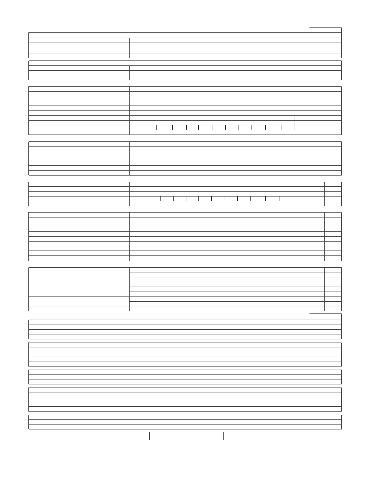
Genesys
1.0 MODEL
1.Rated output voltage(*1)
2.Rated Output Current(*2)
3.Rated Output Power
4.Efficiency at 100/200Vac (*3)
1.0 MODEL
1.Rated output voltage (*1)
2.Rated Output Current (*2)
3.Rated Output Power
1.1 CONSTANT VOLTAGE MODE
1.Max.line regulation ( 0.01% of Vo+ 2mV )(*4)
2.Max load regulation ( 0.01% of Vo+2mV )(*5)
3.Ripple and noise p-p 20MHz
4.Ripple r.m.s 5Hz~1MHz
5.Remote sense compensation/line
6.Temp. coefficient
7.Up-prog. response time, 0~Vo Rated
8.Down-prog response time full-load
9.Down-prog response time no-load
10.Transient response time (*8)
1.2 CONSTANT CURRENT MODE
1.Max.line regulation (0.01% of Io+ 2mA)(*4)
2.Max.load regulation (0.02% of Io+5mA)(*6)
3.Ripple r.m.s 5Hz~1MHz . (*7)
4.Max.line regulation (0.01% of Io+ 2mA)(*4)
5.Max.load regulation (0.02% of Io+5mA)(*6)
6.Ripple r.m.s 5Hz~1MHz .(*7)
7.Temp. coefficient
1.3 PROTECTIVE FUNCTIONS
1. OCP
2. OCP Foldback
3. OVP type
4. OVP trip point
5. Over Temp. Protection
1.4 ANALOG PROGRAMMING AND MONITORING
1.Vout Voltage Programming
2.Iout Voltage Programming
3.Vout Resistor Programming
4.Iout Resistor Programming
5.On/Off control (rear panel)
6.Output Current monitor
7.Output Voltage monitor
8.Power Supply OK signal
9. CV/CC indicator
10. Enable/Disable
1.5 FRONT PANEL
1.Control functions
2.Display
3.Indications
750W/1500W Specifications
™
20-76
12.5-120
8-180
6-200
GEN
V
A
W
%
GEN
V
A
W
mV
mV
mV
mV
V
PPM/°CC
mS
mS
mS
Less than 1mSec for models up to and including 100V. 2msec for models above 100V
mA
mA
mA
mA
mA
mA
PPM/°CC 100PPM/°CC from rated output voltage,following 30 minutes warm up
0~105% Constant Current
Output shut down when power supply change from CV to CC. User selectable.
Inverter shut-down, manual reset by AC input recycle or by OUT button
User selectable , latched or non latched
0~100%, 0~5V or 0~10V, user select. Accuracy and linearity:+/-0.5% of rated Vout.
0~100%, 0~5V or 0~10V, user select. Accuracy and linearity:+/-1% of rated Iout.
0~100%, 0~5/10Kohm full scale,user select.,Accuracy and linearity:+/-1% of rated Vout.
0~100%, 0~5/10Kohm full scale,user select. Accuracy and linearity:+/-1.5% of rated Iout.
By electrical. Voltage: 0~0.6V/2~15V,or dry contact ,user selectable logic
0~5V or 0~10V , accuracy:1% , user selectable
0~5V or 0~10V ,accuracy:1% ,user selectable
TTL High=OK, 0V-Fail 500ohm impedance
CV: TTL high (4~5V) source: 10mA, CC: TTL low (0~0.4V):10mA
Dry contact. Open:off , Short: on. Max. voltage at Enable/Disable in: 6V
Vout/ Iout manual adjust by separate encoders (coarse and fine adjustment selectable)
OVP/UVL manual adjust by Volt. Adjust encoder
AC on/off, Output on/off, Re-start modes (auto, safe), Foldback control (CV to CC), Go to local control
Address selection by Voltage (or current) adjust encoder. Number of addresses:31
RS232/485 and IEEE488.2 selection by IEEE enable switch and DIP switch
Baudrate selection: 1200,2400,4800,9600 and 19,200
Voltage
Current
Voltage, Current, Alarm, Fine, Preview, Foldback, Local, Output On
8
6
180
200
1440
1200
78/81
77/80
8-90
6-100
8
6
90
100
720
600
2.8
2.6
2.8
2.6
60
60
8
8
1
1
100PPM/°CC of rated output voltage,following 30 minutes warm up
80mS , N.L/F.L , resistive load
10
600
500
11
12
23
25
180
200
20
22
41
45
360
400
5.5 70. ~ V
10.5~ 0V 1~15V 1~24V 2~36V 2~44V 5~66V 5~88V 5~110V 5~165V 5~330V 5~660V
4 digits , accuracy: 0.5%+/-1 count
4 digits, accuracy: 0.5%+/-1 count
12.5
120
1500
81/84
12.5-60
12.5
60
750
3.3
3.3
60
8
1
50
700
8.0
17
120
14
29
240
20
76
1520
83/86
20-38
20
38
760
60
800
5.8
12.6
76
9.6
20.2
152
50-30
1500
84/88
80
5~57V
60-25
80
60
50
30
---
---
---
---
7
7
60
8
2
1100
---
---
--5
11
85
1
19
25
1520
1500
84/88
84/88
80-9.5
60-12.5
80
60
9.5
12.5
760
750
10
8
10
8
80
60
8
8
4
3
150mS , N.L/F.L , resistive load
1200
100
2.95
3.25
6.9
7.5
29
38
3.9
4.5
8.8
10
57
75
100
15
1500
84/88
100-7.5
100
7.5
750
12
12
80
8
5
1500
2.75
6.5
23
3.5
8.0
45
150
1500
84/88
150-5
150
750
100
150
2000
2.5
6.0
3.0
7.0
600-2.6
300
600
5
10
5
17
17
10
5
18
35
1500
83/87
300-2.5
300
2.5
750
32
32
120
20
5
2500
2.25
5.5
13
2.5
6.0
25
2.6
1560
83/87
600-1.3
600
1.3
780
62
62
300
60
5
250
250
4000
2.13
5.26
8
2.26
5.52
12
40-38
30-50
40
30
38
50
1520
1500
84/88
83/86
40-19
30-25
40
30
19
25
760
750
6
5
4
4
8
1
60
1.5
900
4.5
10
63
7.0
15
125
6
5
60
8
8
2
1000
3.9
8.8
48
5.8
12.6
95
300-5
150-10
100-15
80-19
1.6 Interface RS232&RS485 or Optional GPIB Interface
80
6
8
0.96
6.0
8.0
10.8
12
180
24
21.6
360
0.96
16
12
12
10.8
360
400
24
21.6
720
800
6
8
60
80
*3: At maximum output power.
*4: 85~132Vac or 170~265Vac, constant load.
mV
mV
mA
mA
mA
mA
mV
mV
mA
mA
mA
mA
mV
mV
V
0.72
200
400
0.72
Model
1. Remote Voltage Programming (16 bit)
Resolution (0.012% of Vo Rated)
Accuracy (0.05%Vo Rated+0.05% of Vo Actual Output)
2. Remote Current Programming (16 bit)
Resolution (0.012% of Io Rated)
Accuracy (0.1% of Io Rated+0.1% of Io Actual Output)
Resolution (0.012% of Io Rated)
Accuracy (0.1% of Io Rated+0.1% of Io Actual Output)
3. Read back Voltage
Resolution (0.012% of Vo Rated)
Accuracy (0.1%Vo Rated+0.1% of Vo Actual Output)
4. Read back Current
Resolution (0.012% of Io Rated )
Accuracy (0.3% of Io Rated+0.1% of Io Actual Output)
Resolution (0.012% of Io Rated )
Accuracy (0.3% of Io Rated+0.1% of Io Actual Output)
5. OVP/UVL Programmi ng
Resolution (0.1% of Vo Rated)
Accuracy (1% of Vo Rated)
*1: Minimum voltage is guaranteed to maximum 0.2% of Vo Rated.
*2: Minimum current is guaranteed to maximum 0.4% of Io Rated
*7: For 6V models the ripple is measured at 2~6V output voltage and full output current. For other models, the ripple is measured at 10~100% output voltage and full output current.
*8: Time for the output voltage to recover within 0.5% of its rated for a load change 10~90% of rated output , Output set-point:10~100%.
Accuracy -Values have been calculated at Vo Rated & Io Rated
12.5
1.50
12.5
120
14.4
240
1.50
7.2
240
14.4
480
125
7.2
25
12
20
2.40
20
4.56
76
9.12
152
2.40
40
4.56
152
9.12
304
20
200
3.60
30
3.0
50
6.0
100
3.60
60
3.0
100
200
30
300
4.80
40
2.28
38
4.56
76
4.80
80
2.28
76
4.56
6
152
40
400
40
30
60
50
7.2
6
60
50
---
1.50
---
25
3.0
3.60
50
60
7.2
6.0
120
100
---
1.50
---
50
3.0
3.60
100
120
60
50
600
500
*5: From No-load to Full-load, constant input voltage.
*6: For load voltage change, equal to the unit voltage rating, constant input voltage.
9.6
80
1.14
19
2.28
38
9.6
160
1.14
38
2.28
76
80
800
100
12
100
0.90
15
1.80
30
12
200
0.90
30
1.80
60
100
1000
150
18
150
0.60
10
1.20
20
18
300
0.60
20
1.20
40
150
1500
300
36
300
0.30
5.0
0.60
10
36
600
0.30
10
0.60
20
300
3000
600
72
600
0.16
2.6
0.32
5.2
72
1200
0.16
5.2
0.32
10.4
600
6000
750W 1500W
750W
X
X
X
X
X
X
X
X
X
X
X
X
X
X
X
X
X
X
X
X
X
X
X
X
X
X
X
X
X
X
X
X
X
X
X
X
X
X
X
X
X
X
X
1500W
X X
X
X
X
X
X
X
X
X
X
X
X
X
X
X
X
X
X
X
X
X
X
X
X
X
X
X
X
X
X
X
X
X
X
X
X
X
X
X
X
X
X
X
X
X
X
X
X
X
X
X
X
X
X
X
X
X
X
X
X
X
X
X
X
3|
Genesys 750W/1500W-1U
TM
Page 5
General Specifications Genesys™ 750W/1500W
2.1 INPUT CHARACTERISTICS
1. Input voltage/freq. (*1)
2. Power Factor 0.99 @100/200Vac, rated output power.
3. EN61000-3-2,3 compliance Complies with EN61000-3-2 class A and EN61000-3-3 at 20~100% output power.
4. Input current 100/200Vac
5. Inrush current 100/200Vac 750W :Less than 25A, 1500W :Less than 50A
6. Hold-up time
2.2 POWER SUPPLY CONFIGURATION
1. Parallel Operation
2. Series Operation
2.3 ENVIRONMENTAL CONDITIONS
1. Operating temp
2. Storage temp
3. Operating humidity
4. Storage humidity
5. Vibration
6. Shock
7. Altitude
2.4 EMC
1.Applicable Standards:
2.ESD
3.Fast transients IEC1000-4-4. 2KV
4.Surge immunity IEC1000-4-5. 1KV line to line, 2KV line to ground
5.Conducted immunity
6.Radiated immunity IEC1000-4-3, 3V/m
7.Conducted emission EN55022B,FCC part 15J-B,VCCI-2
8.Radiated emission
9.Voltage dips EN61000-4-11
10. Conducted emission
11. Radiated emission
2.5 SAFETY
1.Applicable standards:
2.Withstand voltage
3.Insulation resistance
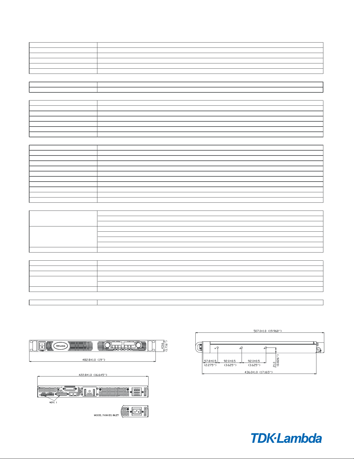
2.6 MECHANICAL CONSTRUCTION
1. Cooling
2. Dimensions (WxHxD) W: 16.64in, H: 1.72in, D: 17.04in (excluding connectors, encoders, handles, etc.)
3. Weight
4. AC Input connector 750W: IEC320 AC Inlet.
5.Output connectors
2.7 RELIABILITY SPECS
1. Warranty 5 years.
85~265Vac continuous, 47~63Hz, single phase
750W :10.5A / 5A, 1500W :21A / 11A
More than 20mS , 100Vac , at 100% load.
Up to 4 identical units in master/slave mode with parallel current summing (Advanced Parallel)
Up to 2 units. with external diodes. 600V Max to Chassis ground
0~50 °C, 100% load.
-20~70 °C
30~90% RH (non-condensing).
10~95% RH (non-condensing).
MIL-810E, method 514.4 , test cond. I-3.3.1. The EUT is fixed to the vibrating surface.
Less than 20G , half sine , 11mSec. Unit is unpacked.
Operating: 10000ft (3000m) , Non operating: 40000ft (12000m).
IEC1000-4-2. Air-disch.-8KV, contact disch.-4KV
IEC1000-4-6, 3V
EN55022A,FCC part 15-A,VCCI-1
EN55022B, FCC part 15-B, VCCI-2.
EN55022A, FCC part 15-A, VCCI-1.
CE Mark, UL60950,EN60950 listed. Vout<60V:Output is SELV , IEEE/Isolated analog are SELV.
60<Vout<400V: Output is hazardous, IEEE/Isolated analog are SELV.
400<Vout<600V:Output is hazardous, IEEE/Isolated analog are not SELV.
Vout<60V models :Input-Outputs (SELV): 3.0KVrms 1min, Input-Ground: 2.0KVrms 1min.
60<Vout<600V models: Input-Haz. Output: 2.5KVrms 1min, Input-SELV: 3KVrms 1min.
Hazardous Output.-SELV: 1.9KVrms 1min, Hazardous Output-Ground:1.9KVrms 1min.
Input-Ground: 2KVrms 1min.
More than 100Mohm at 25 C , 70% RH, 500Vdc
Forced air flow: from front to rear. No ventilation holes at the top or bottom of the chassis; Variable fan speed.
750W: 7Kg (15 Lbs) 1500W: 8.5Kg (18 Lbs)
1500W: Screw terminal block, Phoenix P/N: FRONT-4-H-7.62 , with strain relief
6V to 60V models: Bus-bars (hole Ø 8.5mm). 80V to 600V models: Terminal block, Phoenix P/N: FRONT-4-H-7.62
*1: For cases where conformance to various safety standards (UL, IEC etc.) is required, to be described as 100-240Vac (50/60Hz).
Outline Drawing Genesys™ 750W/1500W Units
NOTE
1. PLUG CONNECTORS INCLUDED WITH THE POWER SUPPLY
2. CHASSIS SLIDES MOUNTING HOLES #10-32 MARKED "A"
GENERAL DEVICES P/N: CC301-00-S160 OR EQUIVALENT
|4
Page 6

Genesys™ Power Parallel and Series Configurations
Parallel operation - Master/Slave:
Active current sharing allows up to four identical units to be connected
in an auto-parallel configuration for four times the output power.
In Advanced Parallel Master/Slave Mode, total current is
programmed and reported by the Master. Up to four supplies
act as one.
Series operation
Up to two units may be connected in series to increase the output
voltage or to provide bipolar output. (Max 600V to Chassis Ground).
Remote Programming via RS-232 & RS-485 Interface
Standard Serial Interface allows daisy-chain control of up to 31
power supplies on the same communication bus with built-in
RS-232 & RS-485 Interface with or without Multi-Drop option.
Programming Options (Factory installed)
New IEEE Multi-Drop Interface
• Allows IEEE Master to control up to 30 (Multi-Drop equipped) slaves over RS-485 daisy-chain
• Only the Master needs be equipped with IEEE Interface
• IEEE 488.2 SCPI Compliant
• Program Voltage • Program Current
• Measure Voltage • Measure Current
• Over Voltage setting and shutdown • Current Foldback shutdown
• Error and Status Messages
New Multi-Drop Slave Option
• Slaves need to be equipped with the MD Slave (RS-485) option
Isolated Analog Programming
• Four Channels to Program and Monitor Voltage and Current.
• Isolation allows operation with floating references in harsh electrical environments.
• Choose between programming with Voltage or Current.
• Connection via removable terminal block: Phoenix MC1,5/8-ST-3.81.
• Voltage Programming, user-selectable 0-5V or 0-10V signal.
Power supply Voltage and Current Programming Accuracy ±1%
Power supply Voltage and Current Monitoring Accuracy ±1.5%
• Current Programming with 4-20mA signal.
Power supply Voltage and Current Programming Accuracy ±1%
Power supply Voltage and Current Monitoring Accuracy ±1.5%
P/N: IEMD
P/N: MD
P/N: IS510
P/N: IS420
LAN Interface
• Meets all LXI-C Requirements
• Address Viewable on Front Panel
• Fixed and Dynamic Addressing
• Fast Startup
Compliant to Class C
• VISA & SCPI Compatible
• LAN Fault Indicators
• Auto-detects LAN Cross-over Cable
• Compatible with most standard Networks
USB Interface
• Allows Serial Connection to USB Port on computer
• Serial commands same as (standard) RS-232/RS-485 Interface
5|
Genesys 750W/1500W-1U
TM
P/N: LAN
P/N: USB
Page 7

Power Supply Identification / Accessories
How to order
GEN
Series
Name
Models 750/1500W
Model
GEN6-100
GEN6-200
GEN8-90
GEN8-180
GEN12.5-60
GEN12.5-120
GEN20-38
GEN20-76
GEN30-25
GEN30-50
GEN40-19
GEN40-38
Factory option P/N
RS-232/RS-485 Interface built-in Standard GPIB (Multi-Drop Master) Interface IEMD
Multi-Drop Slave Interface MD
Voltage Programming Isolated Analog Interface IS510
Current Programming Isolated Analog Interface IS420
LAN Interface (Complies with Class C) LAN
USB Interface USB
600
Output
Voltage
(0~600V)
Output
Voltage
VDC
0~6V
0~8V
0~12.5V
0~20V
0~30V
0~40V
Output
Current
( A )
0~100
0~200
0~90
0~180
0~60
0~120
0~38
0~76
0~25
0~50
0~19
0~38
2.6-
Output
Current
(0~2.6A)
Output
Power
( W )
600
1200
720
1440
750
1500
760
1520
750
1500
760
1520
-
Factory Options AC Cable option is 750W only
Option:
IEMD
MD
IS510
IS420
LAN
-
Region:
E - Europe
J - Japan
I - Middle East
U - North America
USB
Model
GEN50-30
GEN60-12.5
GEN60-25
GEN80-9.5
GEN80-19
GEN100~7.5
GEN100~15
GEN150~5
GEN150~10
GEN300~2.5
GEN300~5
GEN600~1.3
GEN600~2.6
Output
Voltage
VDC
0~50V
0~60V
0~80V
0~100V
0~150V
0~300V
0~600V
Output
Current
0~12.5
0~9.5
0~7.5
0~2.5
0~1.3
0~2.6
( A )
0~30
0~25
0~19
0~15
0~5
0~10
0~5
Output
Power
( W )
1500
750
1500
760
1520
750
1500
750
1500
750
1500
780
1560
AC Cords sets (750W only)
Region
Output Power
AC Cords
Wall Plug
Power Supply
Connector
Part Number
Europe
750W
10A/250 Vac L=2m
INT'L 7/VII
IEC320-C13
P/N: GEN/E
Japan
750W
13A/125 Vac L=2m
IEC320-C13
P/N: GEN/J
10A/250 Vac L=2m
Accessories
1. Communication cable
RS-232/RS-485 Cable is used to connect the power supply to the PC Controller.
Mode
PC Connector
Communication Cable
Power Supply Connector
DB-9F
Shield Ground L=2m
EIA/TIA-568A (RJ-45)
P/N
2. Serial link cable*
Daisy-chain up to 31 Genesys™ power supplies.
Mode
RS-485
* Included with power supply
RS485
GEN/485-9
Power Supply Connector
EIA/TIA-568A (RJ-45)
RS232
DB-9F
Shield Ground L=2m
EIA/TIA-568A (RJ-45)
GEN/232-9
Communication Cable
Shield Ground L=50cm
Middle East
750W
SI-32
IEC320-C13
P/N: GEN/I
North America
750W
13A/125 Vac L=2m
NEMA 5-15P
IEC320-C13
P/N : GEN/U
RS232
DB-25F
FShield Ground L=2m
EIA/TIA-568A (RJ-45)
GEN/232-25
P/N
GEN/RJ45
|6
Page 8
GLOBAL NETWORK
USA
TDK-Lambda Americas Inc.
405 Essex Rd. Neptune, NJ 07753
Tel: +1-732-922-9300 Fax: +1-732-922-1441
E-mail: sales@us.tdk-lambda.com
www.us.tdk-lambda.com/hp
CANADA
ACA TMetrix
5805 Kennedy Road, Mississauga, Ontario, L4Z 2G3
Tel: +1-800-665-7301 Fax: +1-905-890-1959
Email: lambda@aca.ca
tmetrix.com
MEXICO
AcMax de Mexico
39 Poniente 3515 Piso 5 Col. Las Animas
Puebla, Pue. C.P. 72400
Tel: 01-800-211-0060 / (222) 891-8484 Fax: 222-264-1445
Email: info@acmax.mx, Web: www.acmax.mx
BRAZIL
Supplitec
Rua Sena Madureira 455, Belo Hte - 31340-000
Tel: +55-31-3498 1177 Fax: +55-31-3441 0841
www.suplitec.com.br
UK IRELAND
TDK-Lambda UK
Kingsley Avenue
Ilfracombe, Devon EX 34 8ES
Tel: +44-1271-856666 Fax: +44-1271-864894
E-mail: powersolutions@uk.tdk-lambda.com
www.uk.tdk-lambda.com
FRANCE NETHERLANDS SPAIN
TDK-Lambda France
ZAC des Delaches, CS 41077
9 rue Thuillere, 91978 Villebon Courtaboeuf
Tel: +33 1 60 12 71 65 Fax: +33 1 60 12 71 66
www.fr.tdk-lambda.com
GERMANY AUSTRIA SWITZERLAND
TDK-Lambda Germany
Karl-Bold-Str.40, D-77855 Achern
Tel: +49-7841-666-0 Fax: +49-7841-500-0
E-mail: info.germany@de.tdk-lambda.com
www.de.tdk-lambda.com
ITALY
TDK-Lambda Italy
Via dei Lavoratori 128/130
IT 20092 Cinisello Balsamo (MI)
Tel: +39-02-6129-3863 Fax: +39-02-6129-0900
E-mail: info.italia@it.tdk-lambda.com
www.it.tdk-lambda.com
SCANDINAVIA BALTICS
TDK-Lambda Germany
Karl-Bold-Str.40, D-77855 Achern
Tel: +49-7841-666-0 Fax: +49-7841-500-0
E-mail: info.germany@de.tdk-lambda.com
www.de.tdk-lambda.com
JAPAN
TDK-Lambda Corporation
International Sales Division,
3-9-1, Shibaura, Minato-ku,
Tokyo 108-0023
Tel: +81 3-6852-7136 Fax: +81 3-6852-7148
E-mail: t.morimoto@jp.tdk-lambda.com
www.jp.tdk-lambda.com
CHINA
TDK-Lambda Shanghai Office
28F, Xingyuan Technology Building No.418, Guiping Road,
Shanghai, 200233 P.R. CHINA
Tel: +86-21-6485-0777 Fax: +86-21-6485-0666
www.cn.tdk-lambda.com
TDK-Lambda Beijing Office
Room 12B11-12B12, Unit 7 DACHENG SQUARE,
No.28 Xuanwumenxi Street, Xuanwu District Beijing,
100053, P.R. CHINA
Tel: +86-10-6310-4872 Fax: +86-10-6310-4874
www.cn.tdk-lambda.com
TDK-Lambda Hong Kong Office
1 / F. SAE Technology Centre, 6 science Park East Avenue,
HongKong Science Park, Shatin, NT.,
Tel: +852-23766658 Fax: +852-23172150
www.cn.tdk-lambda.com
KOREA
TDK-Lambda Corporation
6F Songok Bldg. 4-1 Soonae-Dong
Pundang-Gu, Songnam-Shi Kyonggi-Do, 463-020
Tel: +82-2-556-1171 Fax: +82-2-555-2706
www.tdk-lambda.co.kr
MALAYSIA
TDK-Lambda Malaysia
Lot 709, Nilai Industrial Estate
71800 Nilai, Negeri Sembilan
Tel: +60-6-799-1130 Fax: +60-6-799-3277
www.my.tdk-lambda.com
SINGAPORE PHILIPPINES
TDK-Lambda Singapore
1008 Toa Payoh North # 06-01/08
Singapore 318996
Tel: +65-6251-7211 Fax: +65-6250-9171
www.sg.tdk-lambda.com
INDIA
TDK-Lambda India
#526, Ground Floor, 10th Main, 7th Cross,
Jeevanbhimanagar, Bangalore 560 075,
Karnataka, India
Tel : +91-80-43550500 Fax :+91-80-43550501
www.in.tdk-lambda.com
ISRAEL
TDK-Lambda Ltd. Israel
Kibbutz Givat Hashlosha Tel-Aviv 48800
Tel: +972-3-9024-333 Fax: +972-3-9024-777
E-mail: info@tdk-lambda.co.il
www.tdk-lambda.co.il
RUSSIA
THAILAND
TDK-Lambda Americas Inc. 405 Essex Road, Neptune, NJ 07753 USA
Tel: +1 732 922 9300 Fax: +1 732 922 1441
www.us.tdk-lambda.com/hp
TDK Logo is a trademark or registered trademark of TDK Corporation
© Copyright 2013 TDK-Lambda Americas Inc.
Part No. 93-507-100 Rev E
 Loading...