

Page 1

G10-500
G80-65
GB10-500
GB80-65
G20-250
G100-50
GB20-250
GB100-50
G30-170
G150-34
GB30-170
GB150-34
G40-125
G300-17
GB40-125
GB300-17
G60-85
G600-8.5
GB60-85
GB600-8.5
Series
Programmable DC Power Supplies
5kW in 1U 0-600V/ 0-500A
Built in LAN, USB, RS-232 & RS-485 Interface
Optional Interface: IEEE488.2 (GPIB)
This manual covers models
USER MANUAL
IA761-04-02
Page 2

TABLE OF CONTENTS
CHAPTER 1: SPECIFICATIONS ................................................................................................. 1
1.1
5000W Series Specifications ...................................................................................... 1
1.2
Standard Unit Low Voltage Outline............................................................................ 5
1.3
Standard Unit High Voltage Outline ........................................................................... 6
1.4
Blank Panel Unit Low Voltage Outline ....................................................................... 7
1.5
Blank Panel Unit High Voltage Outline ....................................................................... 8
1.6
Optional accessories .................................................................................................. 9
1.6.1 Printed User manual ..................................................................................... 9
1.6.2 Serial Port Cables .......................................................................................... 9
1.6.3 Paralleling Cable ........................................................................................... 9
CHAPTER 2: FRONT/REAR PANEL CONTROL & CONNECTORS ............................................... 10
2.1
Introduction ............................................................................................................. 10
2.2
Front Panel Controls................................................................................................. 10
2.3
Front Panel Display and Indicators .......................................................................... 13
2.4
Rear Panel Connections and Controls ...................................................................... 16
2.5
J1 Connector Terminal and Function ....................................................................... 17
2.6
Front Panel Display Messages .................................................................................. 19
2.7
Menu Navigation ...................................................................................................... 20
2.7.1 Introduction ................................................................................................ 20
2.7.2 Exiting a Menu ............................................................................................ 25
CHAPTER 3: LOCAL OPERATION ........................................................................................... 26
3.1
Introduction ............................................................................................................. 26
3.2
Load Connections Options ....................................................................................... 26
3.2.1 Connecting Single Loads, Local Sensing (Default) ...................................... 26
3.2.2 Connecting Single Loads, Remote Sensing ................................................. 26
3.2.3 Connecting Multiple Loads, Radial Distribution Method ........................... 28
3.2.4 Multiple Load Connection with Distribution Terminals ............................. 28
3.2.5 Constant Voltage Mode and Voltage Setting ............................................. 29
3.2.6 Constant Current Mode and Current Setting ............................................. 29
3.2.7 Automatic Crossover .................................................................................. 30
3.2.8 Output On/Off Control ............................................................................... 30
3.2.9 Safe-Start and Auto-Restart Modes............................................................ 31
3.2.10 Viewing Software Revision ......................................................................... 31
3.3
Alarms and Protective Functions ............................................................................. 31
3.3.1 Introduction ................................................................................................ 31
3.3.2 Over Voltage Protection ............................................................................. 32
3.3.2.1 Resetting the OVP Circuit ............................................................. 32
3.3.3 Under Voltage Protection and Under Voltage Limit ................................... 33
3.3.3.1 Activated UVP Alarm .................................................................... 33
3.3.4 Foldback Protection .................................................................................... 34
3.3.4.1 Activated FOLD Alarm .................................................................. 34
3.3.5 Protection Delay ......................................................................................... 35
3.3.6 Over Temperature Protection .................................................................... 35
3.3.7 AC Fail Alarm ............................................................................................... 35
Page 3

3.4
Series Operation ....................................................................................................... 36
3.4.1 Series Connection for Increased Output Voltage ....................................... 36
3.4.2 Series Connection for Positive and Negative Output Voltage .................... 37
3.4.3 Remote Programming in Series Operation ................................................. 37
3.5
Daisy-Chain Connection ........................................................................................... 38
3.5.1 Daisy In Function ........................................................................................ 38
3.6
Rear Panel (J1 Connector) Functions ....................................................................... 39
3.6.1 Interlock Function - Analog On/Off (Enable/Disable) ................................. 39
3.6.2 Enable In Function ...................................................................................... 40
3.6.3 Enable_In Polarity ....................................................................................... 40
3.6.4 Auxiliary Programmed Signals Prog_out_1 and Prog_out_2 ..................... 41
3.6.5 Power Supply OK Signal .............................................................................. 42
3.6.6 CV/CC Signal ................................................................................................ 42
3.7
Parameter Setting Memory ..................................................................................... 43
3.7.1 Default Setting ............................................................................................ 43
3.7.2 Reset ........................................................................................................... 43
3.7.3 Last Setting Memory ................................................................................... 43
3.7.4 Save <1..4> .................................................................................................. 43
3.7.5 Recall <1..4> ................................................................................................ 43
CHAPTER 4: REMOTE ANALOG PROGRAMMING .................................................................. 46
4.1
Introduction ............................................................................................................. 46
4.2
Local/Remote Analog Control .................................................................................. 46
4.3
Local/Remote Analog Indication .............................................................................. 46
4.4
Remote Voltage Programming of Output Voltage and Current .............................. 47
4.5
Remote Resistor Programming of Output Voltage and Output Current ................. 48
4.6
Monitoring of Output Voltage (V_MON) and Current (I_MON) .............................. 49
CHAPTER 5: SERIAL RS232/RS485, USB & LAN INTERFACES .................................................. 50
5.1
Introduction ............................................................................................................. 50
5.2
Configuration ........................................................................................................... 50
5.2.1 Default Setting ............................................................................................ 50
5.2.2 Communication Interface Selection ........................................................... 50
5.2.3 Address Setting ........................................................................................... 51
5.2.4 IP Address Setting ....................................................................................... 51
5.2.5 Baud Rate Setting ....................................................................................... 52
5.2.6 Language Selection (RS232/RS485, USB) .................................................... 52
5.2.7 Setting Unit in Remote, Local Lockout or Local Mode ............................... 53
5.3
Rear Panel RS232/RS485 IN Connector ................................................................... 54
5.4
Rear Panel RS485 OUT Connector............................................................................ 55
5.5
Connecting Power Supply to RS232 or RS485 BUS .................................................. 56
5.6
Rear Panel USB Connector ....................................................................................... 57
5.6.1 USB Getting Started .................................................................................... 57
5.7
Rear Panel LAN ......................................................................................................... 58
5.7.1 Introduction ................................................................................................ 58
5.7.1.1 Feature Summary ......................................................................... 58
5.7.2 Specifications .............................................................................................. 59
5.7.2.1 LAN Specifications ........................................................................ 59
Page 4

5.7.2.2 LAN Command Speed .................................................................. 61
5.7.3 Select the Control Method ......................................................................... 62
5.7.3.1 Control Method Options .............................................................. 62
5.7.3.2 Select LAN Remote Mode ............................................................ 62
5.7.3.3 LAN Status LEDs ........................................................................... 62
5.7.4 Connect to a Network ................................................................................. 63
5.7.4.1 LAN Cable ..................................................................................... 63
5.7.4.2 Types of Networks ....................................................................... 63
5.7.4.3 Power-up the LAN Power Supply ................................................. 64
5.7.4.4 IP Addresses ................................................................................. 65
5.7.4.5 Hostname ..................................................................................... 65
5.7.4.6 Description and DNS Service Names............................................ 66
5.7.5 LAN Setup ................................................................................................... 67
5.7.5.1 View the IP and MAC Addresses .................................................. 67
5.7.5.2 Change the IP Address ................................................................. 67
5.7.5.3 LAN Reset ..................................................................................... 68
5.7.6 Web Pages .................................................................................................. 69
5.7.6.1 Benefits of Web Pages ................................................................. 69
5.7.6.2 Opening the HOME Page ............................................................. 69
5.7.6.3 The Home Page ............................................................................ 70
5.7.6.4 Login Rules ................................................................................... 71
5.7.6.5 DC Power Page ............................................................................. 72
5.7.6.6 LAN Page ...................................................................................... 75
5.7.6.7 HELP Page .................................................................................... 79
5.7.7 Programming Using VISA Drivers ................................................................ 80
5.7.7.1 VISA Description ........................................................................... 80
5.7.7.2 VXI-11 Compatibility .................................................................... 80
5.7.7.3 Opening the VISA Connection ...................................................... 80
5.7.7.4 Communicating Using VISA .......................................................... 80
5.7.8 Programming Using Sockets ....................................................................... 81
5.7.8.1 Socket Description ....................................................................... 81
5.7.8.2 Communicating Using Sockets ..................................................... 81
5.7.8.3 Controller Access: Single and Multiple Clients ............................ 81
5.7.8.4 Input Buffer Requirements .......................................................... 82
5.7.8.5 Message Terminators .................................................................. 82
5.7.8.6 Using TCP Sockets ........................................................................ 82
5.7.8.7 Using UDP Sockets ....................................................................... 83
5.7.9 Connecting Over WAN ................................................................................ 83
5.7.9.1 View Web Pages Over WAN......................................................... 83
5.7.9.2 Use Sockets Over WAN ................................................................ 83
5.8
Multi Power Supply Connection (Daisy-Chain) to RS232, RS485, USB or LAN ......... 84
5.9
GEN Protocol (GEN series communication language) .............................................. 87
5.9.1 Data Format ................................................................................................ 87
5.9.2 End of Message ........................................................................................... 87
5.9.3 Command Repeat ....................................................................................... 87
5.9.4 Checksum .................................................................................................... 87
5.9.5 Acknowledge .............................................................................................. 87
5.9.6 Backspace ................................................................................................... 87
5.10
GEN Command Set Description ................................................................................ 87
5.10.1 General guides ............................................................................................ 87
Page 5

5.10.2 Numeric / Data Type Parameters ............................................................... 88
5.10.3 Command Set Categories ........................................................................... 88
5.10.4 Identification Commands ........................................................................... 89
5.10.5 Initialization Commands ............................................................................. 89
5.10.6 Output Commands ..................................................................................... 90
5.10.7 Global Output Commands .......................................................................... 93
5.10.8 Auxiliary Commands ................................................................................... 95
5.10.9 Status Commands ....................................................................................... 96
5.11
Serial Communication Test Set-Up .......................................................................... 98
5.12
SCPI Protocol ............................................................................................................ 99
5.12.1 Data Format ................................................................................................ 99
5.12.2 End of Message ........................................................................................... 99
5.12.3 End of Command ........................................................................................ 99
5.12.4 Checksum .................................................................................................... 99
5.12.5 SCPI Requirements ..................................................................................... 99
5.12.6 SCPI Command Hierarchy ......................................................................... 100
5.12.7 Header ...................................................................................................... 100
5.12.8 Data Formats ............................................................................................ 100
5.12.9 Commands Notes ..................................................................................... 101
5.13
SCPI Common Commands ...................................................................................... 101
5.14
SCPI Subsystem Commands ................................................................................... 106
5.14.1 Display Subsystem .................................................................................... 106
5.14.2 Initiate Subsystem .................................................................................... 107
5.14.3 Instrument Subsystem .............................................................................. 107
5.14.4 Global Subsystem ..................................................................................... 107
5.14.5 Measure Subsystem.................................................................................. 108
5.14.6 Output Subsystem .................................................................................... 109
5.14.7 Program Subsystem .................................................................................. 111
5.14.8 Source Subsystem ..................................................................................... 115
5.14.9 STATus Subsystem .................................................................................... 120
5.14.10 SYSTem Subsystem ................................................................................... 124
5.14.11 TRIGger Subsystem ................................................................................... 129
5.15
SCPI Commands Summary ..................................................................................... 130
CHAPTER 6: ADVANCED FUNCTIONS ................................................................................. 133
6.1
Sequencer............................................................................................................... 133
6.1.1 LIST Mode ................................................................................................. 133
6.1.2 WAVE Mode .............................................................................................. 134
6.1.3 Sequencer Functions ................................................................................ 135
6.1.3.1 Counter ...................................................................................... 135
6.1.3.2 Dwell .......................................................................................... 135
6.1.3.3 Time ........................................................................................... 135
6.1.3.4 Load ............................................................................................ 135
6.1.3.5 Store ........................................................................................... 135
6.1.3.6 Step ............................................................................................ 136
6.1.3.7 Abort .......................................................................................... 136
6.2
Trigger System ........................................................................................................ 137
6.2.1 Trigger Initialize ........................................................................................ 137
6.2.2 Trigger In ................................................................................................... 137
Page 6

6.2.3 Trigger Out ................................................................................................ 137
6.2.4 Trigger Delay ............................................................................................. 138
6.3
Sequencer + Trigger System Examples ................................................................... 138
6.3.1 WAVE Mode Voltage Programming via Communication Example ........... 138
6.3.2 WAVE Mode Execution via Communication Example .............................. 138
6.3.3 LIST Mode Example ................................................................................... 139
6.3.4 WAVE Mode Example ............................................................................... 140
6.4
Internal Resistance ................................................................................................. 141
6.5
Constant Power Limit ............................................................................................. 142
6.6
Preload Control ...................................................................................................... 143
6.7
OCL – Analog Programming Over Current Limit .................................................... 144
6.7.1 OCL Example (10Volts, 500Amperes supply) ............................................ 144
6.8
Slew-Rate Control .................................................................................................. 145
6.9
Advanced Parallel ................................................................................................... 146
6.9.1 Advanced Parallel Connection (System Assembly) ................................... 146
6.9.2 Load Connection ....................................................................................... 146
6.9.3 Advanced Parallel System Acknowledge .................................................. 147
6.9.3.1 Acknowledge via the front panel ............................................... 148
6.9.3.2 Acknowledge via communication .............................................. 148
6.9.3.3 Acknowledge via communication (Blank Panel master power
supply) 148
6.9.4 Advanced Parallel operation .................................................................... 148
6.9.5 Slave units operation in Advanced Parallel connection ........................... 149
6.9.6 Advanced Parallel fault system ................................................................. 149
6.9.7 Advanced Parallel system identification (*idn?) ...................................... 149
CHAPTER 7: STATUS, FAULT AND SRQ REGISTERS .............................................................. 150
7.1
General ................................................................................................................... 150
7.2
SCPI Language ........................................................................................................ 150
7.2.1 SCPI Register Tree ..................................................................................... 150
7.2.2 Questionable Condition (Fault Register) Group Structure ....................... 151
7.2.3 Operational Condition (Status Register) Group Structure ........................ 152
7.2.4 Standard Event Status Group Structure ................................................... 153
7.2.5 Output Queue ........................................................................................... 154
7.2.6 Error Queue .............................................................................................. 154
7.2.7 Service Request Enable Group Structure.................................................. 157
7.2.8 Determining the Cause of a Service Interrupt .......................................... 158
7.3
GEN Language ........................................................................................................ 159
7.3.1 GEN Register Tree ..................................................................................... 159
7.3.2 Questionable Group (Fault Register) Structure ........................................ 160
7.3.3 Operational Group (Status Register) Structure ........................................ 161
7.3.4 Command Error (“Cxx”) ............................................................................ 161
7.3.5 Execution Error (“Exx”) ............................................................................. 162
7.3.6 Service Request (SRQ) .............................................................................. 162
CHAPTER 8: IEEE OPTION .................................................................................................. 163
8.1
General ................................................................................................................... 163
8.2
IEEE-488.2 Interface ............................................................................................... 163
8.3
Point to Point Connection ...................................................................................... 163
Page 7

8.4
Multi Drop Connection ........................................................................................... 164
8.4.1 Selecting a Single Power Supply in a Multi Drop Chain ............................ 164
8.5
Communication Cables .......................................................................................... 165
8.6
IEEE Controller Configuration ................................................................................ 165
8.7
Power Supply Configuration .................................................................................. 165
8.8
Execution Time ....................................................................................................... 165
8.9
Communication Example ....................................................................................... 166
CHAPTER 9: AIR FILTER OPTION ......................................................................................... 168
9.1
General ................................................................................................................... 168
9.2
Specifications ......................................................................................................... 168
9.3
Maintenance .......................................................................................................... 168
9.3.1 Cleaning Instructions ................................................................................ 168
9.3.2 Assembly Instructions for Standard Power Supplies ................................ 169
9.3.3 Assembly Instructions for Blank Power Supplies (Without Display) ........ 171
CHAPTER 10: MAINTENANCE .............................................................................................. 173
10.1
Introduction ........................................................................................................... 173
10.2
Units under Warranty ............................................................................................ 173
10.3
Periodic Maintenance ............................................................................................ 173
10.4
Adjustments and Calibration .................................................................................. 173
10.5
Parts Replacement and Repairs ............................................................................. 174
10.6
Troubleshooting ..................................................................................................... 174
10.7
Fuse Rating ............................................................................................................. 175
10.1
Einleitung ............................................................................................................... 176
CHAPTER 11: INDEX ............................................................................................................ 179
Page 8

This page intentionally left blank
Page 9

CHAPTER 1: SPECIFICATIONS
1.1
5000W Series Specifications
1
Page 10

2
Page 11

3
Page 12

4
Page 13

1.2
Standard Unit Low Voltage Outline
5
Page 14

1.3
Standard Unit High Voltage Outline
6
Page 15

1.4
Blank Panel Unit Low Voltage Outline
7
Page 16

1.5
Blank Panel Unit High Voltage Outline
8
Page 17

1.6
Optional accessories
1.6.1 Printed User manual
• Printed User manual, order P/N: G/M
1.6.2 Serial Port Cables
• For ordering serial port cables refer to CHAPTER 5:
1.6.3 Paralleling Cable
• Paralleling cable: order P/N: G/P.
9
Page 18

CHAPTER 2: FRONT/REAR PANEL CONTROL & CONNECTORS
No.
Control/Indicator
Description
1
Power Switch
POWER ON/OFF control.
2
Power Supply Model
Model, Voltage & Current Identifier.
value in Preview mode.
function.
5
Operation Mode Indicator
CV/CC/CP Operation mode indicator.
2.1
Introduction
The Power Supply series has a full set of controls, indicators and connectors that allow
the user to setup and operate the unit. Before starting to operate the unit, please read the following
sections for an explanation of the functions, controls and connector terminals.
• Section 2.2: Front Panel Controls
• Section 2.3: Front Panel Display and Indicators.
• Section 2.4: Rear Panel Connections and Controls
•
Section 2.5: J1 Connector Terminal and Function
2.2
Front Panel Controls
Refer to Figure 2–1 and Table 2-1 for description of the Front Panel controls.
Figure 2–1: Front Panel Controls
3 Voltage Encoder and
Button
4 Voltage Display 4-digit 16-segment Voltage display.
Encoder: A high-resolution detent rotary Encoder adjusting
the output voltage and navigating menu.
Button: An auxiliary function to accept the voltage-setting
Normally displays the output voltage.
In Preview mode, the display indicates the program setting of
the output voltage.
In Menu navigation, the display indicates the selected
10
Page 19

No.
Control/Indicator
Description
parameter.
Indicators for description of the front panel Indicators bar.
value, select menu level, and set parameter value.
9
BACK Button
Return one step back in menu navigation mode.
display. *
button, followed by current encoder press. *
6 Current Display 4-digit 16-segment Current display.
Normally displays the output current.
In Preview mode, the display indicates the program setting of
the output current.
In menu navigation, the display indicates the selected
7 Indicators Bar Refer to Figure 2–2 and Table 2-2: Front Panel Display and
8 Current Encoder and
Button
10 PROG Button / Indicator Activates the Program / Sequencer menu.
11 SYST / Lock Front Panel
Button / Indicator
Encoder: A high-resolution detent rotary Encoder adjusting
the output current and navigating menu.
Button: An auxiliary function to accept the current-setting
The Program menu provides Sequencer function control,
Trigger function control, and loads a sequence stored inside
the power supply memory.
Green LED lights when Program menu is active. If Program
menu is active, press PROG button to exit to the main
Activates the System menu.
The System menu provides output sensing point selection
(Local / Remote sense), Interlock function control, Enable
function control, Power Supply OK signal control,
SAVE/RECALL power supply configuration, Programmable
Signals control, Preload function control, Display brightness &
dimming function control, and reset power supply settings.
11
Green LED lights when the System menu is active.
If the System menu is active, press the SYST button to exit
to the main menu.
Lock / Unlock Front Panel buttons by pressing the SYST
Page 20

No.
Control/Indicator
Description
12 CONF Button / Indicator Activates the Configuration menu.
exit to the main menu. *
exit to the main menu. *
to exit to the main menu. *
Green LED lights when the unit is in the Fine mode.
The Configuration menu provides power supply start mode
control, Voltage & Current source control, Analog
Programming / Monitoring range selection, Internal
Resistance function, Constant power limit function, and SlewRate control function.
Green LED lights when the Configuration menu is active.
If the Configuration menu is active, press the CONF button to
13 PROT Button / Indicator Activates the Protection menu.
The Protection menu provides OVP setting, UVL setting, UVP
function control, Foldback function control, and OCL function
ON/OFF control.
Green LED lights when the Protection menu is active.
If the Protection menu is active, press the PROT button to
14 COMM Button / Indicator Activates the Communication menu.
The Communication menu provides communication interface
selection, power supply address selection, LAN settings
control, communication baud-rate selection, communication
language selection, and software revision information.
Green LED lights when the Communication menu is active.
If the Communication menu is active, press the COMM button
15 FINE Button / Indicator Voltage/Current Fine/Coarse adjustment control.
Operates as a toggle switch.
In the Fine mode, Voltage and Current encoders operate in
high-resolution mode.
12
In the Coarse mode, Voltage and Current encoders operate in
standard-resolution (approx. 3 turns for full voltage/current
rated scale).
Page 21

No.
Control/Indicator
Description
Green LED lights when the PREV mode is active.
Green LED lights when the DC Output is enabled.
16 PREV Button / Indicator Press the PREV button to display the Output Voltage and
Current Limit settings.
The display shows the settings for 5 seconds.
If buttons are not pressed for 5 seconds, the display returns
back to show actual output voltage and current.
If Voltage or Current values are changed, and there is no
keypress for 15 seconds, the display returns back to show
actual output Voltage and Current.
17 OUT Button / Indicator Output ON/OFF control.
Press OUTPUT to set the output ON or OFF.
Table 2-1: Front Panel Controls
2.3
NOTE
* If a menu is active, and there is no key press within 15 seconds, power supply returns to the
main display (OFF or actual Voltage and Current display).
Front Panel Display and Indicators
Refer to Figure 2–2 and Table 2-2 for description of the Front Panel display and indicators.
Figure 2–2: Front Panel Display and Indicators
13
Page 22

No.
Control/Indicator
Description
Section
function.
2
Operation Mode Indicator
CV/CC/CP operation mode indicator.
parameter.
LFP is on if the Front Panel is locked.
AUTO is on if the Auto-Start mode is active.
SAFE is on, if the Safe-Start mode is active.
FOLD C is on if Foldback CC is active.
active, regardless of the power supply output state.
ext I is on if Analog Current Programming channel is active.
1 Voltage Display 4-digit 16-segment Voltage display.
Normally displays the output voltage.
In preview mode, the display indicates the program setting of
the output voltage.
In menu navigation, the display indicates the selected
3 Current Display 4-digit 16-segment Current display.
Normally displays the output current.
In preview mode, the display indicates the program setting of
the output current.
In menu navigation, the display indicates the selected
4 LFP Indicator Locked Front Panel indicator.
5 AUTO Indicator AUTO-Start indicator.
6 SAFE Indicator SAFE-Start indicator.
7 FOLD VI Indicator Foldback indicator.
FOLD V is on if Foldback CV is active.
8 Power / Address Indicator If power supply output is ON, actual output power is
displayed.
If power supply output is OFF, power supply address is
displayed.
* The address is displayed while Communication menu is
9 ext V / ext I Indicators External Voltage / External Current Analog Programming
Indicators.
ext V is on if Analog Voltage Programming channel is active.
14
Page 23

No.
Control/Indicator
Description
Section
communication (RS232/485, USB, LAN, OPTional).
RS232 or RS485 communication type is selected.
USB communication type is selected.
LAN communication type is selected.
Optional communication type is selected.
power supply is ready to receive trigger-in signal.
The Indicator is blinking if a sequence is running.
10 REM Indicator REMOTE indicator.
REM is on if power supply is controlled by a remote
11 RS Indicator Recommended Standard indicator.
12 USB Indicator Universal Serial Bus indicator.
13 LAN Indicator Local Area Network indicator.
14 OPT Indicator Optional communication type indicator.
15 TRIG Indicator Trigger Indicator.
TRIG is on if the trigger-in is enabled and initialized.
16 Active Memory-Cell
Indicator
Display active memory cell.
1,2,3,4 – A sequence is loaded from cells 1,2,3 or 4
_ - A sequence is loaded from a PC
Table 2-2: Front Panel Display and Indicators
15
Page 24

2.4
No.
Connection
Description
Section
2
Ground Stud
Functional Ground connection M4x8 Stud.
IPC 5/ 4-GF-7,62 for 150V to 600V models.
compensation of load wire drop.
Button between 5 to 10 sec. Refer to Table 3-5 & Table 3-6.
6
Paralleling Connectors
Master/Slave connectors, mini I/O type
Red status indicator (close to RJ45) – LAN fault / Not connected.
the remaining units are chained, Remote-Out to Remote-In.
a serial communication bus.
10
USB Connector
USB interface connector, type B.
signals
the output potential.
12
Optional Interface
Position for optional communication interface.
Rear Panel Connections and Controls
Refer to Figure 2–3 and Table 2-3 for description of the Rear Panel connections and controls.
Figure 2–3: Rear Panel Connection and Controls
1 AC Input Connector Connector type: PC 5/ 4-G-7,62.
3 DC Output Bus-Bar /
Connector
4 Remote Sense Connector A Connector for remote sensing connections.
5 Reset Button Set default power supply settings (Factory Reset). Press Reset
7 LAN Connector +
Indicators *
8 Serial In Connector RJ-45 type connector, used for connecting power supplies to
Bus-bars for 10V to 100V models,
Connect to the load for regulation of the load voltage and
LAN interface connector, RJ-45 type + LAN status indicators.
Green LED on RJ45 connector – Link / Activity.
Amber LED on RJ45 connector – Speed. Lit – 100Mbps,
otherwise 10Mbps.
Green status indicator (close to RJ45) – Connection active.
RS232 or RS485 port of a computer for remote control
purposes. When using several power supplies in a power
system, the first unit Serial-In is connected to the computer and
9 Serial Out Connector RJ-45 type connector, used for chaining power supplies to/from
11 Isolated control and
Isolated analog Control and monitoring signals, isolated from
Table 2-3: Rear Panel Connections and Controls
16
Page 25

No.
Connection
Description
Section
power supply output.
supply status. High level is OK.
type, low level is OK.
4
CV/CC
Output for Constant-Voltage / Constant-Current mode indication.
(analog) programming mode.
programming of the output Voltage and Current.
the Output Current.
9
18
26
1
10
19
2.5
NOTE
* LAN Connector LEDs (Green & Amber) and Red Status Indicators might lit in Power Switch OFF
state.
WARNING
Refer to the Safety & Installation Manual for any connect/disconnect of any connector on the rear
panel.
J1 Connector Terminal and Function
Control and monitoring signals are SELV.
Connector Technical Information:
Connector type: 618026325223, WURTH
DB26HD Receptacle type: 10090769-P264ALF, FCI
Wire: AWG 24-28
Figure 2–4: J1 Connector Terminals and Functions
1 Daisy In / SO Input for Series Operation / Input for Shut Off control of the
2 Daisy Out / PS_OK #2 Output for Series Operation / Output #2 for indication of power
3 PS_OK #1 Output #1 for indication of power supply status. Open Collector
5 LOC/REM MON Output for indicating if the unit is in Local (digital) or Remote
6 LOC/REM SELECT Input for selecting between Local (digital) or Remote (analog)
7 IPGM Input for Remote (analog) voltage/resistance programming of
17
Page 26

No.
Connection
Description
Section
the Output Voltage.
9
NOT USED
open) or voltage source. Selectable signal polarity.
11
COM
COMMON. Return for all signals.
12
COM
COMMON. Return for all signals.
13
COM
COMMON. Return for all signals.
14
COM
COMMON. Return for all signals.
15
NOT USED
16
NOT USED
17
COM
COMMON. Return for all signals.
18
COM
COMMON. Return for all signals.
open) or voltage source.
20
Programmed Signal 2
General Purpose Open Drain Port 2.
21
Programmed Signal 1
General Purpose Open Drain Port 1
edge triggered, pulse width: min. 10usec.
23
Trigger Out
Trigger output, positive edge, pulse width: min. 100usec.
24
NOT USED
25
I_MON
Output for monitoring the power supply output Current.
26
V_MON
Output for monitoring the power supply output Voltage.
8 VPGM Input for remote (analog) voltage/resistance programming of
10 ENA_IN Enable / Disable the power supply output by dry-contact (short /
19 ILC Enable / Disable the power supply output by dry-contact (short /
22 Trigger In Power supply trigger input for sequencer operations. Positive
Table 2-4: J1 Connector Terminals and Functions
18
Page 27

Display Text
Text Description
Display Text
Text Description
OUTPUT
LOCK
OFF
UNLOCK
Interface
SENSE
RS232
LOCAL
RS485
REMOTE
USB
INTERLOCK
LAN
ON
ADDRESS
ENABLE
IP
ENABLE POLARITY
MAC
NORMAL
BAUD RATE
REVERSE
LANGUAGE
POWER SUPPLY OK DELAY
SCPI
SAVE
GENESYS
RECALL
REVISION
FACTORY RESET
OVP
DEFAULT
UVL
SURE
UVP
YES
UVP DELAY
NO
FOLDBACK
PIN 1
FOLDBACK DELAY
PIN 2
CC
CURRENT
CV
VOLTAGE
OVER CURRENT LIMIT
PRELOAD
START
DISPLAY
SAFE
BRIGHTNESS
AUTO
DIMMING BRIGHTNESS
VOLTAGE SOURCE
DIMMING DELAY
2.6
Front Panel Display Messages
Table 2-5 shows the various messages shown on the display in different operating modes.
OUT
OFF
INTFC
RS232
RS485
USB
LAN
ADR
IP
MAC
BAUD
LANG
SCPI
GEN
REV.
ovp
uvl
UVP
UVP.DL
FOLD
FLD.DL
CC
CV
OCL
START
SAFE
AUTO
V.SRC
LOCK
ULOCK
SENSE
LOCAL
REM
ILC
ON
ENA
ENA.PL
NORM
REV
PSO.DL
SAVE
RECAL
FRST
DEFLT
SURE
YES
NO
PIN 1
PIN 2
CURR
VOLT
PREL
DISP
BRT
DM.BRT
DM.DL
19
Page 28

Display Text
Text Description
Display Text
Text Description
PANEL
TRIGGER
EXTERNAL VOLTAGE
INIT
EXTERNAL RESISTANCE
ABORT
CURRENT SOURCE
LOAD
RANGE
TRIGGER INPUT
INTERNAL RESISTANCE
EXTERNAL
CONSTANT POWER
BUS
POWER
CONTINUES
SLEW
TRIGGER DELAY
CURRENT SLEW UP
TRIGGER OUT
CURRENT SLEW DOWN
FUNCTION STROBE
VOLTAGE SLEW UP
OPTIONAL COMMUNICATION
VOLTAGE SLEW DOWN
RESISTANCE
PANEL
E.VOL
E.RES
C.SRC
RANGE
R.INT
C.PWR
POWER
SLEW
CSL.UP
CSL.DN
VSL.UP
VSL.DN
TRIG
INIT
ABORT
LOAD
TRG.IN
EXT
BUS
CONT
TRG.DL
TRG.OU
FSTR
OPT
RES
2.7
Menu Navigation
2.7.1 Introduction
Power Supply series contains the following five independent menus:
• COMMUNICATION
• PROTECTION
• CONFIGURATION
• SYSTEM
• PROGRAM
1. To enter a menu, press COMM, PROT, CONF, SYST or PROG button.
An appropriate LED lights indicating that a menu is active.
2. Navigate the menu by rotating the Voltage encoder to scroll through the selected Menu
functions.
Table 2-5: Front Panel Display Messages
3. Rotate the Current Encoder to select a parameter or a parameter value.
4. Press the Current Encoder to accept a desired parameter value.
5. If the parameter is accepted, the display blinks once indicating the parameter is accepted.
20
Page 29

RS232 RS485 USB LANINTFC
0ADR 1 31
9. 6 K 38.4 K 57. 6 K 115.2 K
BAUD
GENLANG SCPI
G: xx. xxx
REV.
Voltage encod er 1 step rotate
Current encod er 1 step rotate
OPT
--------------------- built_in --------------------- --- optional - --
IP1
0 255
IP4
RESET
1--4
IP
MAC 1
MAC 6
1--6
MAC
0 255
00 FF
00 FF
LAN
Function ( Voltage Disp lay)
Parameter (Current Display)
LAN Interface
Active
NO
COMM
ENTER
ENTER
CURRENT
ENCODER
VOLTAGE
ENCODER
6
COMMUNIC ATION MENU
ENTER
ENTER
Level down
YES
Note: Press Current enc oder to select required parameter. Current display b links - Parameter accepted
For LAN or OPT Interfaces, GE N lang uage is not av aila ble
19.2 K
SURE
ENTER
LAN
Interface
Not Active
Voltage encod er multiple steps rotate
Current encod er multiple step s rotate
Figure 2–5: COMMUNICATION Menu Diagram
21
Page 30

OVP
MIN
UVL
MAX
PROT
ENTER
CURRENT
ENCODER
VOLTAGE
ENCODER
0 MAX
OFF
UVP
ON
0. 1
UVP.DL
25.5
FOLD
OFF
FLD.DL
CV
UVP
ON
FOLD
CC/ CV
CC
0. 1 25.5
PROTECTION MENU
OCL
OFF ON
UVP
OFF
FOLD
OFF
Voltage encod er 1 step r otate
Current encod er 1 step r otate
Function (Voltage Display)
Parameter (Current Dis play)
ENTER
Level down
Note: Press Current enc oder to select required parameter. Cur rent d isplay blinks - Parameter accepted
Voltage encod er multiple steps rotate
Current encod er multiple steps rotate
Figure 2–6: PROTECTION Menu Diagram
22
Page 31

START
CONF
ENTER
CURRENT
ENCODER
VOLTAGE
ENCODER
V. SRC
PANEL E.RES
5
RANGE
10
E. VOL
CONFIGURATI ON MENU
R. SRC
V. SRC
C. SRC
PANEL E.RES
E. VOL
R. INT
OFF
ON
RES
0. 001 1 . 000
POWER
MIN MAX
C.P OW
ON
C. PWR
OFF
ON
SAFE AUTO
R. SRC
V. SRC
SLEW
OFF VOLT
CURR
CSL.UP
0. 0001 999.99
VSL.UP
CSL.DN
0. 0001 999.99
VSL.DN
SLEW
OFF
SLEW
VOLT
SLEW
CURR
C.P OW
OFF
R.I NT
OFF
R.I NT
ON
Voltage encod er 1 step rotate
Current encod er 1 step rotate
Function (Voltage Display)
Parameter (Current Display)
ENTER
Level down
Note: Press Current enc oder to select required para meter. Current d isplay blinks - Parameter accepted
Voltage encod er multiple steps rotate
Current encod er multiple step s rotate
Figure 2–7: CONFIGURATION Menu Diagram
23
Page 32

DM.DL
SENSE
PANEL
SYST/
ENTER
CURRENT
ENCODER
VOLTAGE
ENCODER
SYSTEM MENU
LOCAL REM
ENA
OFF ON
ILC
OFF ON
PSO.DL
0. 000 10.000
SAVE
1 2 3
4
RECAL
1 2 3
4
FRST
DEFLT
NO
SURE
YES
ENTER
PIN 1
OFF ON
PIN 2
OFF ON
PREL
DISP
BRT
DM.BRT
DM.DL
Note: Max DM.BRT value is limited to BRT v alu e - 1
DM.BRT
0 3
15 30
115. 2
60
BRT
1 4
DM.B RT
0--3
LOCK
ULOCK
Present mode
LOCA L
Present mode
REMOTE / LOCKED
ENA.PL
REV NORM
Note: M enu dis play s alter native
para meter o nly, no selection.
OFF
ENTER
ENTERENTER
DM.B RT
OFF
OFF
ON
DM.B RT
0--3
DM.B RT
OFF
Voltage encod er 1 step rotate
Current encod er 1 step rotate
Function ( Voltage Display)
Parameter ( Current Display)
ENTER
Level down
Note: Press Current encoder to selec t required pa ramete r. Cur rent d isplay blinks - Parameter acce pted
Voltage encod er mult iple steps rotate
Current encod er mult iple steps rotate
Figure 2–8: SYSTEM Menu Diagram
24
Page 33

TRIG
PROG
ENTER
CURRENT
ENCODER
TRIG
VOLTAGE
ENCODER
TRG.OU
OFF TRIG
EXT
TRG.IN
BUS
FSTR
PROG RAM MENU
INIT
ABORT
Aborted / No inita ilzed
Inita ilzed
LOAD
1 2 3 4
OFF
CONT
ON
0. 000
TRG.DL
10.00
Voltage encod er 1 step rotate
Current encod er 1 step rotate
Function (Voltage Disp lay)
Parameter (Current Dis play)
ENTER
Level down
Note: Press Current enc oder to select required parameter. Current display b links - Parameter a ccepted
Voltage encod er m ultiple steps rotate
Current encod er multiple steps rotate
Note : Menu di sp lays alternativ e
para meter o nly, no selection.
2.7.2 Exiting a Menu
There are three ways to exit a Menu:
• Press the active Menu button.
Appropriate MENU LED turns OFF. The display shows the present power supply status.
• Press the Back button multiple times, corresponding to the depth inside the Menu.
Appropriate MENU LED turns OFF. The display shows the present power supply status.
Figure 2–9: PROGRAM Menu Diagram
• No action for 15 sec.
Appropriate MENU LED turns OFF. The Display shows the present power supply status.
25
Page 34

CHAPTER 3: LOCAL OPERATION
Load lines, twisted pair, shortest length possible.
+V
POWER
SUPPLY
+
LOAD
-
-V
3.1
Introduction
This Chapter describes the operating modes that do not require programming and monitoring the
power supply via its communication interfaces: LAN, USB, RS232/RS485, Optional communication
or by remote analog signals. Ensure that the REM indicator on the display is off (indicating Local
mode). If the REM indicator is on, press the Front Panel SYST button, PANEL ULOCK is seen on the
display. Press Current encoder to unlock.
For information regarding remote analog programming, refer to CHAPTER 4:
For information regarding usage of the LAN, USB or serial communication interfaces refer to
section 5.2.2.
The power supply has three operating modes. The two basic operating modes are: Constant
Voltage mode and Constant Current mode. The mode in which the power supply operates at any
given time depends on the output voltage setting, output current limit setting, and the load
resistance. The third operation mode is the Constant Power mode. In this mode a power limit is
created by an internal algorithm. Refer to section 6.5 for further explanation.
3.2
Load Connections Options
3.2.1 Connecting Single Loads, Local Sensing (Default)
Figure 3–1 shows recommended load connections for a single load. This connection is for local
sensing mode. Local sensing is suitable for applications where load regulation is less critical.
Figure 3–1: Single Load Connection, Local Sensing
3.2.2 Connecting Single Loads, Remote Sensing
There is a potential shock hazard at the sense point when using power supply with an output
voltage greater than 60VDC. Ensure that the connections at the load end are shielded to prevent
accidental contact with hazardous voltages.
26
WARNING
Page 35

+V
POWER
SUPPLY
c
c
+
LOAD
-
c
c
-V
+S
-S
Load lines, twisted pair, shortest length possible.
Sense lines.
Twisted pair o r shielded
WARNUNG
Bei Einsatz einer Stromversorgung mit einer Ausgangsspannung von über 60VDC besteht am
lastseitigen Sense-Punkt die potentielle Gefahr eines elektrischen Schlags. Stellen Sie sicher,
dass die Anschlüsse an der Last abgedeckt sind, um versehentlichen Kontakt mit gefährlicher
Spannung zu vermeiden.
CAUTION
When using shielded sense wires, ground the shield in one place only. The location can be the
power supply chassis or one of the output terminals.
Figure 3–2 shows recommended remote sensing connection for single loads. Remote sensing is
used when, in Constant Voltage mode, the load regulation is important at the load terminals. Use
twisted or shielded wires to minimize noise pick-up. If shielded wires are used, the shield should be
connected to the ground at one point, either at the power supply chassis or the load ground. The
optimal point for the shield ground should be determined by experimentation.
Figure 3–2: Remote Sensing, Single Load
27
Page 36

3.2.3 Connecting Multiple Loads, Radial Distribution Method
Load lines,
Twisted pa irs, sh ortest length possible
LOA D #1
-
+
LOA D #2
-
+
LOA D #3
-
+
+V
POWER
SUPPLY
-V
POWER
SUPPLY
c
c
+V
c
c
-V
+S
-S
LOA D #1
-
+
LOA D #2
-
+
LOA D #3
-
+
Distribution ter minal
Figure 3–3 shows multiple loads connected to one supply. Each load should be connected to the
power supply’s output terminals using separate pairs of wires. It is recommended that each pair of
wires will be as short as possible and twisted or shielded to minimize noise pick-up and radiation.
Figure 3–3: Multiple Loads Connection, Radial Distribution, Local Sense
3.2.4 Multiple Load Connection with Distribution Terminals
If remotely located output distribution terminals are used, the power supply output terminals should
be connected to the distribution terminals by a pair of twisted and/or shielded wires. Each load
should be separately connected to the remote distribution terminals (see Figure 3–4).
If remote sensing is required, the sensing wires should be connected to the distribution terminals or
at the most critical load.
In remote sense, the power supply will compensate for voltage drop on the load wires. Refer to the
Specifications (1.1) for the maximum voltage drop on load wires. The voltage drop is subtracted
from the total voltage available at the output.
28
Figure 3–4: Multiple Loads Connection with Distribution Terminal
Page 37

3.2.5 Constant Voltage Mode and Voltage Setting
In Constant Voltage mode, the power supply regulates the output voltage at the selected value,
while the load current varies as required by the load.
While the power supply operates in Constant Voltage mode, the CV indicator on the display
illuminates.
1. Adjust the output voltage, when the power supply output is enabled (Output On) or disabled
(Output Off). There are three options to set output voltage:
(a) When the output is enabled, rotate the Voltage encoder knob to program the output
voltage. This method affects output voltage immediately.
(b) When the output is enabled, press the PREV button and then rotate the Voltage encoder to
a required value. Press the Voltage encoder to select the required value. The display will
blink once to acknowledge the setting. This method affects output voltage only after
acknowledgement by encoder press. Exit the PREV menu by pressing the Back button or
the PREV button.
(c) When the output is disabled, press the PREV button and then rotate the Voltage encoder
to a required value. Press the Voltage encoder to select the required value. The display will
blink once to acknowledge the setting. Exit the PREV menu by pressing the Back button or
the PREV button.
2. Set voltage programming resolution to the Coarse or Fine adjustment.
(a) Press the FINE button to select between the lower (about 1% of rated voltage) and higher
(setting least significant digit seen on the voltage display) resolution.
(b) The FINE LED illuminates when the resolution is set to Fine.
NOTE:
If after completing the adjustment, the display shows a different value than the setting, the power
supply may be at current limit. Check the load condition and the power supply current limit setting.
NOTE:
The maximum and minimum setting values of the output voltage are limited by the Over Voltage
protection and Under Voltage limit settings. Refer to section 3.3.2 and section 3.3.3 for more
details.
3.2.6 Constant Current Mode and Current Setting
In the Constant Current mode, the power supply regulates the output current at the selected value,
while the voltage varies with the load requirement.
While the power supply is operating in Constant Current mode, the CC indicator in the display
illuminates.
29
Page 38

1. Adjust the output current, when the power supply output is enabled (Output On) or disabled
(Output Off). There are three options to set output voltage:
(a) When the output is enabled, rotate the Current encoder knob to program the output
current. This method affects output current immediately.
(b) When the output is enabled, press the PREV button and then rotate the Current encoder to
a required value. Press the Current encoder to select the required value. The display will
blink once to acknowledge the setting. This method affects output current only after
acknowledgement by encoder press. Exit the PREV menu by pressing the Back button or
the PREV button.
(c) When the output is disabled, press the PREV button and then rotate the Current encoder
to a required value. Press the Current encoder to select the required value. The display will
blink once to acknowledge the setting. Exit the PREV menu by pressing the Back button or
the PREV button.
2. Set current programming resolution to Coarse or Fine adjustment.
(a) Press the FINE button to select between the lower (about 1% of rated voltage) and higher
(setting least significant digit seen on the voltage display) resolution.
(b) The FINE LED illuminates when the resolution is set to Fine.
3.2.7 Automatic Crossover
When the power supply operates in the Constant Voltage mode, while the load current is increased
to greater than the current limit setting, the power supply will automatically switch to the Constant
Current mode. If the load is decreased to less than the current limit setting, the power supply will
automatically switch back to the Constant Voltage mode.
3.2.8 Output On/Off Control
The Output On/Off enables or disables the power supply output.
The Output On/Off can be activated from the front panel using the OUTPUT button or from the
communication interface. The OUTPUT button can be pressed at any time (except in the Front
Panel Lock mode, Remote control mode by communication, LLO mode or when a Fault condition
exists).
When the output is disabled, the output voltage and current fall to zero, the display shows OUTP OFF.
Press the OUTPUT button to recover from Faults such as: OVP, UVP, and FOLD faults, after the
Fault conditions have been removed.
30
Page 39

3.2.9 Safe-Start and Auto-Restart Modes
At AC turn on, the power supply can start at the last setting of the Output Voltage and Current limit
with the output enabled (Auto-restart), or it can start with the output disabled (Safe mode).
1. Press the Configuration button. Display shows START SAFE or START AUTO, depending on the
currently selected start mode.
2. Rotate the Current encoder to select between SAFE or AUTO start mode.
3. Press the current encoder to select Safe mode or Auto-restart mode.
The default setting is Safe mode.
Automatic Start Mode (AUTO)
The power supply is restored to last operation setting. Upon start-up, the output is enabled or
disabled according to the last setting.
Safe Start Mode (SAFE)
The power supply is restored to last operation setting and sets the Output to Off state.
At start-up, the output is disabled and the output voltage and current are zero (settings are
preserved). To enable the output momentarily, press the OUTPUT button.
3.2.10 Viewing Software Revision
Via the Front Panel Menu, it is possible to view the installed software revision.
1. Press the COMM button. COMM (GREEN) LED illuminates.
2. Rotate the Voltage encoder until the Rev. message appears on the Voltage display, and the
installed software revision number appears on the Current display.
3.3
Alarms and Protective Functions
3.3.1 Introduction
There are several conditions that cause alarm (RED LED blinks). All alarms affect the output.
When an alarm occurs, the respective fault will appear on the display and the alarm LED
illuminates. It is possible that more than one fault (alarm) may be triggered, but only the first will be
shown on the display. If the second fault is still active when the first fault is removed, then the
second fault will be displayed.
The following protective functions are incorporated in the power supply:
• OVP - Over Voltage Protection
• UVP - Under Voltage Protection
• ILC - Interlock
• ENA - Enable
• FOLD - Fold Back Constant Current or Constant Voltage
• AC FAIL - AC Power failure
• OTP - Over Temperature Protection
31
Page 40

3.3.2 Over Voltage Protection
Model
Max. OVP
Min. OVP
10V
12.0V
0.5V
20V
24.0V
1.0V
30V
36.0V
2.0V
40V
44.1V
2.0V
60V
66.15V
5.0V
80V
88.2V
5.0V
100V
110.2V
5.0V
150V
165.37V
5.0V
300V
330.75V
5.0V
600V
661.5V
5.0V
The OVP circuit protects the load in the event of a remote or local programming error or a power
supply failure. The protection circuit monitors the voltage at the power supply sense points thus
providing the protection level at the load. Upon detection of an Over Voltage condition, the power
supply output will shut down.
Setting the OVP Level
The OVP can be set when the power supply output is Enabled (On) or Disabled (Off). The
minimum setting level is 5% above the output voltage, or the value in Table 3-1, whichever is
higher. The maximum setting level is shown in Table 3-1.
1. Press the PROT button.
PROT (GREEN) LED illuminates. OVP message appears on the display.
2. Rotate the Current encoder to adjust the OVP level.
3. Press the Current encoder to select the required OVP level.
The display blinks once to acknowledge the setting.
4. Exit the PROT menu by pressing the Back button or the PROT button.
Table 3-1: Maximum/Minimum OVP Setting Levels
3.3.2.1 Resetting the OVP Circuit
To reset the OVP circuit after activation:
1. Reduce the power supply Output Voltage setting below the OVP set level.
2. Ensure that the load and the sense wiring is connected properly.
Four methods to reset the OVP circuit.
• Pressing the OUTPUT button
• AC recycle
• On/Off recycle by analog control (Interlock/Enable)
• Sending a communication command to enable output.
32
Page 41

3.3.3 Under Voltage Protection and Under Voltage Limit
The UVL function prevents output voltage setting below the UVL set value, and prevents an
adjustment of the output voltage below a certain limit.
The UVP function prevents power supply operation, if the output voltage is below the UVL set
value. Upon detection of an Under Voltage condition, the power supply output will shut down. The
combination of the UVP/UVL and the OVP functions, enables the user to create a protection
window for the sensitive load circuitry.
Setting the UVP/UVL Mode and Level
The UVP/UVL can be set when the power supply output is Enabled (On) or Disabled (Off).
UVL setting value is limited at the maximum level to approximately 5% below the Output Voltage
setting. Attempting to adjust the value above this limit will result in no response to the adjustment
attempt. The minimum value setting is zero. UVP must be turned "ON" to be operational.
1. Press the PROT button. PROT (GREEN) LED illuminates.
2. Rotate the Voltage encoder until UVL appears on the Voltage display.
3. Rotate the Current encoder to set the required UVL level.
4. Press the current encoder to select the required level. The display blinks once to acknowledge
the setting.
5. Rotate the Voltage encoder until UVP Appears on the Voltage display.
6. Rotate the Current encoder to set UVP ON/OFF.
7. Press the Current encoder for selection. The display blinks once to acknowledge the setting.
8. Set the UVP delay time by rotating the Voltage encoder until UVP.DL appears.
The delay can be set by the Current encoder between 0.1~25.5sec.
9. Press the Current encoder to select the required delay.
The display blinks once to acknowledge the setting.
10. Exit the PROT menu by pressing the Back button or the PROT button.
3.3.3.1 Activated UVP Alarm
When the UVP is activated, the power supply output shuts down. The display shows UVP FAULT.
RED alarm LED blinks 1/2Hz frequency.
33
Page 42

3.3.4 Foldback Protection
Foldback protection will shut down the power supply output if power supply operation mode
crosses over from CC to CV or from CV to CC, according to a selected operation mode.
There are three states of Foldback protection.
• OFF (default)
• CV
• CC
For CC (or CP) to CV protection mode, the setting should be CV.
For CV (or CP) to CC protection mode, the setting should be CC.
Setting the Foldback Protection
The Foldback can be set when the power supply output is Enabled (On) or Disabled (Off).
1. Press the PROT button. PROT (GREEN) LED illuminates.
2. Rotate Voltage encoder until FOLD OFF Appears.
3. Rotate the Current encoder to set the required Foldback state (CV or CC).
4. Press the Current encoder for selection of Foldback state. The display blinks once to
acknowledge the setting.
If the CC state is selected, the FOLD I indicator appears on the display.
If the CV state is selected, the FOLD V indicator appears on the display.
5. To turn off the Foldback protection, select FOLD OFF, following the same procedure above.
Foldback indicator disappears from the display.
6. Exit the PROT menu by pressing the Back button or the PROT button.
7. Set the Foldback delay time by rotating the Voltage encoder until FLD.DL appears.
The delay can be set by the Current encoder between 0.1~25.5sec.
8. Press the Current encoder to select the required delay.
The display blinks once to acknowledge the setting.
9. Exit the PROT menu by pressing the Back button or the PROT button.
3.3.4.1 Activated FOLD Alarm
When the Foldback is activated the power supply output shuts off. The display shows FOLD FAULT,
and the alarm LED blinks with 1/2 Hz frequency.
34
Page 43

3.3.5 Protection Delay
Foldback protection delay is the time between feedback transition (CV to CC transition or vice
versa) event occurrences to output shutdown.
UVP protection delay is the time between UVL crossover point events to output shutdown.
At output OFF -> ON transition, additional 500ms delay is added.
Total protection delay = 500ms + delay setting.
3.3.6 Over Temperature Protection
The OTP circuit shuts down the power supply before the internal components can exceed their
safe internal operating temperature. When an OTP shutdown occurs, the display shows OTP FAULT,
and the alarm LED blinks RED with 1/2 Hz frequency. Resetting the OTP circuit can be automatic
(non-latched) or manual (latched) depending on the power supply mode: Safe start mode or Auto-
restart mode.
NOTE
• Safe start mode: The power supply stays off after the OTP condition has been removed. The
display shows OUT OFF.
• Auto-restart mode: The power supply recovers to its last setting automatically after the OTP
condition is removed.
3.3.7 AC Fail Alarm
The AC Fail alarm indicates whether the AC input has been shut down or AC input is incorrect.
When any of these faults occur, the display shows AC FAULT, Output power is disabled, and the
alarm RED LED blinks 1/2 Hz frequency.
Safe start mode: The power supply stays off after AC power returns. The display shows OUT OFF.
Auto-restart mode: The power supply recovers to its last setting automatically when the AC power
returns.
35
Page 44
3.4
+V
POWER
SUPPLY
+
LOAD
-V
POWER
SUPPLY
-V
+V
-
(*)
(*)
Series Operation
Power supplies of the same model can be connected in series to obtain an increased output
voltage. Split connection of the power supplies gives positive and negative output voltage.
WARNING
When power supplies are connected in series, and the load or one of the output terminals is
grounded, no point may be at a greater potential of +/- 200VDC from ground for models up to
100VDC rated output and +/- 600VDC from ground for models 150 ~ 600VDC rated output.
WARNUNG
Wenn Stromversorgungen in Reihe geschaltet werden und die Last oder eine der
Ausgangsklemmen geerdet ist, darf kein Anschluss ein größeres Spannungspotential bei den
Ausgangsmodellen bis 100VDC von +/- 200VDC gegenüber Erde aufweisen. Bei den
Ausgangsmodellen 150 ~ 600VDC kann das maximale Spannungspotential bis zu +/- 600VDC
betragen.
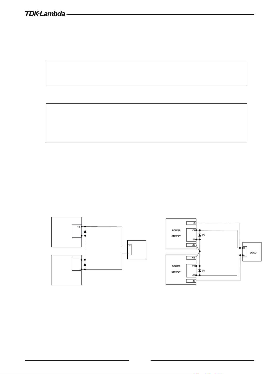
3.4.1 Series Connection for Increased Output Voltage
Two units are connected so that their outputs are summed. Set the current limit of each power
supply to the maximum that the load can handle without damage. It is recommended that diodes be
connected in parallel with each unit output to prevent reverse voltage during start up sequence or
in case one of the units shuts down. Each diode should be rated to at least the power supply rated
output voltage and output current. Refer to Figure 3–5 for series operation with local and remote
sensing.
Series connection, local sensing
(*) Diodes are user supplied.
Figure 3–5: Series Connection, Local and Remote Sensing
36
Series connection, remote sensing
Page 45

(*)
(*)
POWER
SUPPLY
+
LOAD
COM.
-V
POWER
SUPPLY
-V
+V
-
+V
connected in series.
Section 4.5 for details.
3.4.2 Series Connection for Positive and Negative Output Voltage
In this mode, two units are configured as positive and negative output.
Set the current limit of each power supply to the maximum that the load can handle without
damage. It is recommended that diodes be connected in parallel with each unit output to prevent
reverse voltage during start-up or in case one of the units shuts down. Each diode should be rated
to at least the power supply rated output voltage and output current. Refer to Figure 3–6 for this
operating mode.
3.4.3 Remote Programming in Series Operation
Programming by external voltage: The analog programming circuits of this power supply
Using the SO function and (\PS_OK_OUT)
signal:
Programming by external resistor : Programming by external resistor is possible. Refer to
37
Figure 3–6: Series Connection for Positive/Negative Output Voltages
(*) Diodes are user supplied.
are isolated from the output potentials. Therefore, the
circuits used to control each series connected unit don't
have to be separated and floated from each other.
DAISY_IN signal (J1-1) serves as Output Shut OFF (SO)
via daisy chain connection.
This signal is used only for the Daisy Chain application,
connected to DAISY_OUT signal (J1-2) of a master unit.
The signal is referenced to the isolated interface
(COM_SELV: J1-11, 12, 13, 14). The function is active
after initial high to low transition.
(\PS_OK_OUT) signal is Power Supply OK– Open
Collector type which indicates output status (DC
On/Off). The signal is referenced to the isolated
interface (COM_SELV: J1-11, 12, 13, 14). The
COM_SELV terminals of the units can be connected to
obtain a single control circuit for the power supplies
Page 46

Out connectors. Refer to section 2.4 for details.
C OM SE LV
J1-11
J1-2
C OM SE LV
Dais y out
J1-11
J1-2
Dais y out
Dais y in
J1-1
POWER SUPPL Y # 3
J1-11
J1-2
Dais y out
POWER SUPPL Y # 1
Dais y in
J1-1
Dais y in
J1-1
POWER SUPPL Y # 2
C OM SE LV
3.5
Programming via serial communication ports
(RS232/RS485, USB):
The Communication ports are referenced to the
COM_SELV, which is isolated from the power supply
output potential. Therefore, power supplies connected in
series can be chained using the Remote-In and Remote-
Daisy-Chain Connection
It is possible to configure a multiple power supply system to shut down all units when a fault
condition occurs in one of the units. When the fault is removed, the system recovers according to a
preset state: Safe start mode or Auto-restart mode.
If a fault occurs in one of the units, its ”Daisy out” signal will be set to low level and the display will
indicate the fault. The other units will shut off and their displays will indicate SO FAULT. When the
fault condition is removed, the units will recover to their last setting according to their respective
Safe start or Auto-restart setting.
Figure 3–7: Daisy-Chain Connection shows connection of three units, however the same
connection method may be applied to systems with more units.
3.5.1 Daisy In Function
DAISY_IN signal is used only for Daisy Chain application, connected to DAISY_OUT signal of a
master unit. It is an isolated signal from the power supply output.
Connection to the signal is made via pin J1-1 (DAISY_IN) and pin J1-11 (COM_SELV).
The DAISY_IN pin accepts 2V to 25V as high level signal, 0V to 0.6V as low level signal or Open-
Short contact to enable or disable the power supply output.
The Daisy in function will be activated only after initial High to low transition is detected.
Thus, in the Auto start mode, the output will be enabled after applying AC power, even if DAISY_IN
is in low level. DAISY_IN is ignored after power supply output OFF event, Power Switch OFF
event & Faults.
After high to low transition is detected, the SO will enable or disable the power supply output
according to the signal level or the short/open applied to J1. When the external DAISY_IN is
triggered, the power supply will display SO FAULT on the voltage display.
Figure 3–7: Daisy-Chain Connection
38
Page 47

SO signal level
(J1-1 – J1-11)
Power Supply Output
DAISY_
PS_OK Level
Front Panel ILC
Setting
ILC Input
Power Supply
Output
Display
Alarm LED
– Default
Open or Short
On
Voltage/Current
Open Or 2~30V
Off
Short Or 0~0.6V
On
Voltage/Current
For signal details, refer to Table 3-2.
2-30V or Open
0-0.6V or Short
On
Off (SO FAULT)
(J1-2 – J1-11)
High
Low
Out Level
Table 3-2: Daisy_In Signal Definition
3.6
Rear Panel (J1 Connector) Functions
3.6.1 Interlock Function - Analog On/Off (Enable/Disable)
Interlock signal (\ILC_IN) serves as power supply output enable control via a switch or relay.
Use the Interlock function to enable or disable the output as emergency shutoff or door open
switch. It is an isolated signal from the power supply output. Connection to the signal is made via
pin J1-19 (\ILC_IN) and pin J1-11 (COM_SELV).
The ILC function can be enabled or disabled via communications or the Front panel as follows:
1. Press the SYST button. SYST (GREEN) LED illuminates.
2. Rotate the Voltage encoder until ILC OFF appears.
(J1-3 – J1-11)
Low
High (Open Collector)
3. Rotate Current encoder to select ILC ON or ILC OFF. Press Current encoder to accept. The
display blinks once to acknowledge the setting.
4. Exit SYST menu by pressing the Back button or the SYST button.
OFF
ON
ILC FAULT
Off
On
Off
Table 3-3: Interlock Functions and Settings
CAUTION
To prevent possible damage to the unit, do not connect any of the Enable /Disable inputs to the
positive or negative output potential.
NOTE
Safe Start mode - If the Interlock fault condition clears while units are in the Safe Start mode, the
power supply returns to Output Off mode.
39
Auto-Restart mode - The output will automatically return to the previous setting.
The following faults will require \ILC_IN recycle: UVP, OVP or Foldback.
Page 48

3.6.2 Enable In Function
ENA_IN signal serves as power supply output enable control. Connection to the signal is made via
pin J1-10 (ENA_IN) and pin J1-11 (COM_SELV), which are isolated from the power supply output.
ENA_IN is reported by a display message ENA FAULT, RED alarm LED is blinking 1/2 Hz frequency.
ENA_IN can be enabled/disabled via communications or the Front Panel as follows:
1. Press the SYST button. SYST (GREEN) LED illuminates.
2. Rotate the Voltage encoder until ENA OFF appears.
3. Rotate Current encoder to select ENA ON or ENA OFF. Press Current encoder to accept. The
display blinks once to acknowledge the setting.
4. Exit SYST menu by pressing the Back button or the SYST button.
3.6.3 Enable_In Polarity
This function provides the ability to select ENA_IN signal polarity.
Polarity selection via the Front Panel is performed as follows:
1. Press the SYST button. SYST (GREEN) LED illuminates.
2. Rotate the Voltage encoder until ENA.PL appears.
3. Rotate Current encoder to select NORM or REV. Press Current encoder to accept. The display
blinks once to acknowledge the setting.
4. Exit SYST menu by pressing the Back button or the SYST button.
To prevent possible damage to the unit, do not connect any of the Enable /Disable inputs to the
positive or negative output potential.
CAUTION
40
Page 49

Front Panel
ENA Setting
ENA Polarity
ENA
Power Supply
Output
Display
Alarm LED
– Default
Open or Short
On
Voltage/Current
Open Or 2~30V
Off
Short Or 0~0.6V
On
Voltage/Current
Open Or 2~30V
On
Voltage/Current
Short Or 0~0.6V
Off
NOTE
Safe Start mode - If the Interlock fault condition clears while units are in the Safe Start mode, the
power supply returns to Output Off mode.
Auto-Restart mode - The output will automatically return to the previous setting.
The following faults will require \ENA_IN recycle: UVP, OVP or Foldback.
Input
OFF
ON NORM
-
ENA FAULT
NORM
REV
REV
ENA FAULT
Table 3-4: Enable Functions and Settings
3.6.4 Auxiliary Programmed Signals Prog_out_1 and Prog_out_2
The programmed signal Prog_out_1 (J1-21) and Prog_out_2 (J1-20) are open drain, maximum
input voltage 25V and maximum sink current 100mA. Programmed signals can be controlled via
the Front Panel or via communications. Selection of "OFF" via front panel or communication will
result low output signal level and selection of "ON" via front panel or communication will result high
output signal level.
Pin 1 or Pin 2 settings are set as follows:
1. Press the SYST. Button. SYST (GREEN) LED illuminates.
2. Rotate the Voltage encoder until PIN 1 OFF or PIN 2 OFF appears.
3. Rotate Current encoder to select PIN 1 ON or PIN 1 OFF, PIN 2 ON or PIN 2 OFF. Press Current
encoder to accept. The display blinks once to acknowledge the setting.
Off
On
Off
Off
On
41
4. Exit the SYST menu by pressing the Back button or the SYST button.
CAUTION:
Do not connect Prog_out_1 and Prog_out_2 to a voltage source higher than 25V. Always connect
Prog_out_1 and Prog_out_2 to the voltage source with a series resistor to limit the sink current to
less than 100mA.
Page 50

3.6.5 Power Supply OK Signal
Power Supply OK signal (\PS_OK_OUT) indicates power supply output state (ON/OFF).
It is an open collector signal at J1-3, referenced to COM_SELV at J1-11 (Isolated Interface
Common). When a fault condition occurs or power supply output is Off, \PS_OK_OUT level is high,
maximum input voltage is 30V. When no fault condition occurs or power supply output is On,
\PS_OK_OUT level is low with maximum sink current of 10mA.
The \PS_OK_OUT signal can be delayed via Front Panel setting or via communication. The delay
affects \PS_OK_OUT signal OFF -> ON transition only, ON -> OFF is not affected.
This function is used to prevent signal rise before output reaches set value.
PS_OK delay setting:
1. Press SYST Button, SYST (GREEN) LED illuminates. Rotate Voltage encoder until PSO.DL
Appears.
2. Rotate the Current encoder to set the required delay time. Press on the current encoder to
select the desired delay value.
3. The display will blink once to acknowledge the setting.
4. Exit SYST menu by pressing the Back button or the SYST button.
3.6.6 CV/CC Signal
CV/CC_MON signal indicates the power supply operation mode (Constant Voltage / Constant
Current /Constant Power).
CV/CC_MON signal is an open collector output, maximum voltage of 30V, at J1-4, referenced to
COM_SELV at J1-11 (Isolated Interface Common). When the power supply operates in the
Constant Voltage mode, the Constant power mode or OUTPUT OFF, CV/CC_MON signal is high.
When the power supply operates in the Constant Current mode, CV/CC_MON signal output is low
(0-0.6V), with maximum 10mA sink current.
Do not connect CV/CC signal to a voltage source higher than 30VDC. Always connect CV/CC
signal to the voltage source with a series resistor to limit the sink current to less than 10mA.
CAUTION
NOTE
For all rear panel functions and for navigation of all menus refer to the Rear Panel menus in
section 2.4 & section 2.7.
42
Page 51

3.7
Parameter Setting Memory
Power supply has the following memory configuration modes:
3.7.1 Default Setting
This function sets all parameters to their default state, as defined in Table 3-5 and Table 3-6.
Factory Reset settings can be restored via Front Panel menu or communication command. The
following states are cleared: OVP, Foldback and UVP.
1. Press SYST Button, SYST (GREEN) LED illuminates. Rotate Voltage encoder until FRST DEFLT
Appears.
2. Press Current encoder to accept default settings.
3. Display shows SURE NO. Rotate current encoder to display SURE YES. Press Current encoder to
accept. The display will blink once to acknowledge the setting.
4. Exit SYST menu by pressing the Back button or the SYST button.
NOTE
If FRST function is performed by communication command, the power supply loses
communication due to communication settings change and lost addressing.
3.7.2 Reset
This function sets basic parameters to their default state (as defined in Table 3-5).
It is set via communication only. The following states are cleared: OVP, Foldback and UVP.
3.7.3 Last Setting Memory
Last setting stores power supply state into the non-volatile memory. Stored settings are defined in
Table 3-5. Settings are stored at AC fault condition. Settings are restored at power supply AC ON.
3.7.4 Save <1..4>
This function stores parameters into the non-volatile memory. It is set via the Front Panel or
communication.
User can save up to 4 sets of parameters. Refer to Table 3-5 for available Store parameter sets.
To save the Front Panel setting, perform the following steps:
1. Press the SYST button. SYST (GREEN) LED illuminates. Rotate Voltage encoder until SAVE 1
appears.
2. Rotate Current encoder to select the desired memory cell (1-4). Accept by pressing Current
encoder. The display blinks once to acknowledge the setting.
3. Exit the SYST menu by pressing the Back button or the SYST button.
3.7.5 Recall <1..4>
This function recalls parameters from the non-volatile memory. It is set via the Front Panel or
communication.
43
Page 52

Function
Factory Reset
(Default Settings)
Reset
Last
Setting
Save & Recall
Power Supply Start Mode
SAFE
SAFE
+
+
Power Supply Output State
OFF
OFF + OFF
Voltage Set Point [V]
0 0 +
+
Current Set Point [A]
1.05 * RATED
0 + +
(Model Dependent)
(Model Dependent)
Under Voltage Level (UVL) [V]
0 0 +
+
Under Voltage Protection (UVP) Mode
OFF
OFF + +
Under Voltage Protection (UVP) Delay [S]
01.0
01.0
+
+
Fold-Back Mode
OFF
OFF + +
Fold-Back Delay [S]
01.0
01.0
+
+
Constant Power Function
OFF
OFF + +
Constant Power Set Point [W]
RATED
SVUL*SCUL
+
+
Slew Mode
OFF
OFF + -
Voltage Slew Up / Down [V/mS]
999.99
999.99
+
-
Current Slew Up / Down [A/mS]
999.99
999.99
+
-
Internal Resistance Function
OFF
OFF + +
Internal Resistance Set Point [Ω]
0.001
0.001
+
+
Voltage Reference Programming Source
DIG - +
-
Current Reference Programming Source
DIG - +
-
Analog Mode Current Limit (OCL)
OFF - +
-
Analog Programming & Monitoring Range [V]
5 - +
-
Programmable Pin 1
OFF
OFF + +
Programmable Pin 2
OFF
OFF + +
Front Panel Remote Mode
LOCAL
REM
+*2
-
Front Panel LOCK
OFF - +
-
Output Sense (LOC / REM)
LOC - +
-
Interlock (ILC) Function
OFF - +
-
Enable (ENA) Function
OFF - +
-
User can recall up to 4 sets of parameters. Refer to Table 3-5 for available Recall parameter sets.
To recall the Front Panel setting, perform the following steps:
1. Press the SYST button. SYST (GREEN) LED illuminates. Rotate Voltage encoder until RECAL 1
appears on the display.
2. Rotate Current encoder to select the desired memory cell (1-4). Accept by pressing Current
encoder. The display blinks once to acknowledge the setting.
3. Exit the SYST menu by pressing the Back button or the SYST button.
Over Voltage Protection (OVP) [V] 1.1 * RATED
or 1.2 * RATED
1.1 * RATED
or 1.2 * RATED
+ +
44
Page 53

Function
Factory Reset
(Default Settings)
Reset
Last
Setting
Save & Recall
Enable (ENA) Polarity
REV - +
-
Power Supply OK (PS_OK) Delay [S]
00.01
- + -
Preload
ON - +
-
Communication Interface
USB - +
-
Communication Power Supply Address
06 - +
-
Communication Baud Rate [Baud]
115200
- + -
Communication Language
SCPI
- + -
Spec.)
Special Voltage Upper Limit (SVUL)
RATED
- + -
Special Current Upper Limit (SCUL)
RATED
- + -
Depends on
(SCPI
only)
Event registers
00000
00000
-
-
Power-On Status Clear
1 - +
-
Display Brightness
3 - +
-
Display Dim Delay [S]
30 - +
-
Display Dim Brightness
2 - +
-
Factory Calibration Parameters
Factory Calibration
- - -
Function
Factory Reset (Default Settings)
IP Address DHCP configuration
DHCP
Ping server
Enabled
Auto-Negotiation
Enabled
Description (Service Name)
TDK-LAMBDA Supply <last 3 serial number digits>
Password
Clear field (None)
Hostname
G[H]<rated voltage>-<rated current>
VXI-11 Discovery
Enabled
Keep-Alive Time [S]
1800
mDND & DNS-SD
Enabled
LAN parameters Default (Ref. LAN
Enable registers 00000 -
- + -
*PSC
-
Table 3-5: Non-Volatile Memory Parameters
Table 3-6: LAN Non-Volatile Memory Parameters
45
Page 54

CHAPTER 4: REMOTE ANALOG PROGRAMMING
(V.SRC)
(C.SRC)
2~30V Or Open
Not applicable
Not applicable
Off
0~0.6V Or Short
PANEL
PANEL
Off
0~0.6V Or Short
E.VOL Or E.RES
PANEL
0~0.6V Or Short
0~0.6V Or Short
PANEL
E.VOL Or E.RES
0~0.6V Or Short
0~0.6V Or Short
E.VOL Or E.RES
E.VOL Or E.RES
0~0.6V Or Short
4.1
Introduction
The Rear Panel connector J1 allows the user to program the power supply output voltage and
current with an analog device. J1 also provides monitoring signals for output voltage and output
current. The programming range and monitoring signals range can be selected between 0-5V or 0-
10V using the Front Panel menu or communication.
4.2
Local/Remote Analog Control
Signal LOC/REM_INPUT J1-6 accepts electrical signal or dry contact (Referenced to J1-11) to
select between Local or Remote Analog programming of the output voltage and current. Refer to
Table 4-1 for signal levels.
In Local mode, the output voltage and current can be programmed via the Front Panel Voltage and
Current encoders or via the Communication interface. In the Remote Analog mode, the output
voltage and current can be programmed by analog voltage or by programming resistors via J1
contacts. Refer to Analog Programming Setting Table 4-1 & Figure 4–1 for remote voltage
programming connection or Figure 4–2 for remote resistor programming connection.
4.3
Local/Remote Analog Indication
Contact J1-5 is an open collector output that indicates if the power supply is in the Local mode or in
the Remote Analog mode. To use this output, connect a pull-up resistor to a voltage source of
maximum 30VDC. Choose the pull-up resistor so that the sink current is less than 10mA when the
output is in low state. J1-5 signal is low if J1-6 is low and at least one of the Analog control modes
is selected. Refer to Analog Programming Setting Table 4-1.
LOC/REM_INPUT Voltage source
Current source
LOC/REM_MON
Table 4-1: Local/Remote Analog Control and Indication
46
Page 55

DC
5/10V
DC
5/10V
OUTPUT VOLTAGE PROGRAMMING
OUTPUT CURRENT P ROGRAMMING
678
11
4.4
Remote Voltage Programming of Output Voltage and Current
For Voltage Analog Programming wiring, refer to Figure 4–1.
Set the Remote Programming settings as follows:
1. Short the pin J1-6 to J1-11.
2. Press the CONF button. CONF (GREEN) LED illuminates.
3. Rotate the Voltage encoder until V.SRC or C.SRC appears on the voltage display.
4. Rotate the Current encoder to set E.VOL. Press the Current encoder for selection, display blinks
once to acknowledge the setting.
5. Rotate the Voltage encoder until RANGE appears on the voltage display.
6. Rotate the Current encoder to set 5 or 10 (External 5V or 10V). Press the Current encoder for
selection, display blinks once to acknowledge the setting.
7. Exit CONF menu by pressing the Back button or the CONF button.
CAUTION
When programming from J1, use a programming source with floated outputs to maintain the
isolation of the power supply.
Figure 4–1: J1-Remote Voltage Programming Connection
47
Page 56

4.5
OUTPUT VOLTAGE PROGRAMMING
OUTPUT CURRENT PROGRAMMING
678
11
Optional sets upper limit
Optional sets upper limit
Pro gr ammi ng
Resistor
Optional sets
low e r limit
Pro gr ammi ng
Resistor
Optional sets
low e r limit
Remote Resistor Programming of Output Voltage and Output Current
For resistive programming, the internal current sources for output voltage and/or output current
control, supply 1mA current through external programming resistors connected between J1-8 and
J1-18 and between J1-7 and J1-18. The outcome voltage, as a result, of current flow across the
programming resistors is used as a programming voltage for the power supply. Resistance of 0~5
Kohm or 0~10 Kohm can be selected to program the output voltage and current from zero to full
scale. A variable resistor can control the output over the entire range, or a combination of variable
resistors and series/parallel resistors can control the output over a restricted portion of the range.
For Resistor Analog Programming wiring, refer to Figure 4–2.
Set the Remote Programming settings as follows:
1. Short the pin J1-6 to J1-11.
2. Press the CONF button, CONF (GREEN) LED illuminates.
3. Rotate Voltage encoder until V.SRC or C.SRC appears on the voltage display.
4. Rotate the Current encoder to set E.RES. Press the Current encoder for selection, display blinks
once to acknowledge the setting.
5. Rotate the Voltage encoder until RANGE appears on the voltage display.
6. Rotate the Current encoder to set 5 (5Kohm) or 10 (10Kohm). Press the Current encoder for
selection, display blinks once to acknowledge the setting.
7. Exit CONF menu by pressing the Back button or the CONF button.
Figure 4–2: J1-Remote Resistor Programming Connection
48
Page 57

NOTES:
1. The power supply can be programmed to up to 108% of the rated output voltage and current.
However, it is forbidden to operate the power supply over its voltage and current ratings.
Performance is not guaranteed when operating the power supply above its ratings.
2. Communication: In the Remote Analog mode, power supply parameters can be programmed
and read back via the Communication port, except for output voltage and current settings.
3. To maintain the temperature stability specification of the power supply, the resistors used for
programming should be stable and low noise resistors, with a temperature coefficient of less
than 50ppm.
4. Radiated emissions, FCC requirements: FCC requirements for radiated emissions: use a
shielded cable for the Analog control signals. When using a non-shielded cable, attach an EMI
ferrite suppressor to the cable, as close as possible to the power supply.
5. Front panel PREV button: Use the PREV button to display the output voltage and current
settings defined by the Encoders or Communication.
4.6
Monitoring of Output Voltage (V_MON) and Current (I_MON)
The J1 connector, located on the rear panel, provides analog signals for monitoring the output
voltage and output current. Selection of the voltage range between 0-5V or between 0-10V is made
via the Front Panel or communication.
The monitoring signals represent 0 to 100% of the power supply output voltage and output current.
The monitor outputs have 500 ohm series output resistance.
CAUTION
Ensure that the sensing circuit has an input resistance of greater than 500 Kohm or accuracy will
be reduced.
Perform range selection as follows:
1. Press the CONF button. CONF (GREEN) LED illuminates.
2. Rotate the Voltage encoder until RANGE appears on the voltage display.
3. Rotate the Current encoder to set 5 or 10 (5V or 10V monitoring range). Press the Current
encoder for selection, display blinks once to acknowledge the setting.
4. Exit CONF menu by pressing the Back button or the CONF button.
49
Page 58

CHAPTER 5: SERIAL RS232/RS485, USB & LAN INTERFACES
Function Level
Display
Parameter Level
Display
Description
RS232
RS485
USB
LAN
Address
0…31
Baud Rate
BAUd
9600…115200
9.6K...115.2K
Language
LANG
SCPI
SCPI
GEN
GEN
IP Address
IP
IP1…IP4
IP1...IP4
MAC Address
MAC
MAC1…MAC6
MAC1...MAC6
LAN Reset
LAN
RESET
RESET
5.1
Introduction
This chapter describes the set-up, operation, commands, and communication protocols of the
power supplies via serial communication interfaces: RS232, RS485, or USB, and LAN.
5.2
Configuration
RS232
Communication
Interface
INTFC
RS485
USB
LAN
OPT OPT
Available only if optional
communication card is installed.
ADR
Table 5-1: Front Panel Setup
5.2.1 Default Setting
Refer to Table 3-5: Non-Volatile Memory Parameters and Table 3-6: LAN Non-Volatile Memory
Parameters for factory default settings.
5.2.2 Communication Interface Selection
The power supply communication interface can be set to RS232, RS485, USB, LAN, or OPT *.
1. Press the COMM button.
COMM LED illuminates. INTFC message appears on the Voltage display.
2. Rotate the Current encoder to select a required communication interface.
0...31
50
3. Press the Current encoder to accept a parameter.
When the parameter is accepted, the display blinks once.
4. To exit the menu, press the COMM button or the BACK button.
NOTE
* OPT option is available only if an optional communication card (i.e. IEEE) is installed.
Page 59

5.2.3 Address Setting
The power supply address can be set to any address in the range of 0 to 31.
1. Press the COMM button.
COMM LED illuminates. INTFC message appears on the Voltage display.
2. Rotate the Voltage encoder 1 step clockwise.
ADR message appears on the Voltage display.
3. Rotate the Current encoder to select the required address: 0...31.
4. Press the Current encoder to accept a parameter.
When the parameter is accepted, the display blinks once.
5. To exit the menu, press the COMM button or the BACK button.
5.2.4 IP Address Setting
The power supply IP address setting is split into four fields: IP1.IP2.IP3.IP4. These four fields
represent an IPv4 address. Each IP field can be set to any value in the range of 0 to 255.
1. Press the COMM button.
COMM LED illuminates. INTFC message appears on the Voltage display.
2. Rotate the Voltage encoder 2 steps clockwise.
IP message appears on the Voltage display.
3. Rotate the Current encoder to select a required IP address field: IP1, IP2, IP3 or IP4.
4. Press Current encoder to accept a parameter.
When the parameter is accepted, the display blinks once.
5. Rotate the Current encoder to select the required IP address field: 0...255.
6. Press the Current encoder to accept the parameter.
When the parameter is accepted, the display blinks once.
7. To exit the menu, press the COMM button or the BACK button twice.
NOTE
The IP Address Setting is available only if the LAN communication interface is selected.
51
Page 60

5.2.5 Baud Rate Setting
Five optional rates are possible: 9600, 19200, 38400, 57600 and 115200.
1. Press the COMM button.
COMM LED illuminates. INTFC message appears on the Voltage display.
2. Rotate the Voltage encoder 2 steps clockwise *.
BAUD message appears on the Voltage display.
3. Rotate the Current encoder to select required baud rate: 9600, 19200, 38400, 57600 or 115200 **.
4. Press the Current encoder to accept a parameter.
When the parameter is accepted, the display blinks once.
5. To exit the menu, press the COMM button or the BACK button.
* If LAN interface is active, rotate the Voltage encoder 5 steps clockwise.
NOTE
** If LAN interface is active, baud rate is locked to 115200.
5.2.6 Language Selection (RS232/RS485, USB)
Power Supply Series implement the SCPI standard interface to control the unit by
remote communication. In addition, GEN legacy commands subset is provided for ease of use and
backward compatibility.
1. Press the COMM button.
COMM LED illuminates. INTFC message appears on the Voltage display.
2. Rotate the Voltage encoder 3 steps clockwise *.
LANG message appears on the Voltage display.
3. Rotate the Current encoder to select the required language: GEN or SCPI **.
4. Press the Current encoder to accept a parameter.
When the parameter is accepted, a display blinks once.
5. To exit the menu, press the COMM button or the BACK button.
NOTE
* If LAN interface is active, rotate the Voltage encoder 6 steps clockwise.
** If LAN or optional (i.e. IEEE) interface is active, only SCPI language is available.
52
Page 61

5.2.7 Setting Unit in Remote, Local Lockout or Local Mode
If power supply is in Local mode, it can receive communication commands & queries. If a
command is received, power supply will execute and change its mode to Remote. If a query is
received, power supply will reply and remain in the Local mode.
Remote Mode:
If a communication command is received, power supply will perform the command and change its
mode to Remote.
If power supply is in Remote mode, the REM indicator illuminates.
Parameters cannot be changed via the front panel. If an attempt is made to change parameters via
the front panel, Current display shows REM message for 2 seconds.
It is possible to return to Local mode by pressing the front panel SYST button, followed by Current
encoder press or via communication command SYSTem:REMote[:STATe] LOC.
Local Lockout Mode:
If power supply is in Local Lockout mode, REM indicator illuminates.
Parameters cannot be changed via the front panel. If an attempt is made to change parameters via
the front panel, Current display shows LLO message for 2 seconds.
It is possible to return to the Remote mode by the communication command
SYSTem:REMote[:STATe] REM or by AC power recycle.
53
Page 62

5.3
1 2 3 4 5 6 7 8
Shield
Rear Panel RS232/RS485 IN Connector
RS232/485 in the interface is accessible through the rear panel RS232/485 IN connector. The
connector is eight contacts, shielded RJ-45 type. The connector is used to connect power supplies
in RS232 or RS485 configurations. Refer to Figure 5–1 for the connector description.
(Connector enclosure)
Figure 5–1: J4 Rear Panel RS232/485 IN Connector Pinout
• RS232/485 IN Pinout:
• 1 – RS232 RX
• 2 – RS232 TX
• 3 – RS485 RXD-
• 4 – RS485 TXD-
• 5 – RS485 TXD+
• 6 – RS485 RXD+
• 7 – NC (Not Connected)
• 8 – SG (Signal Ground)
NOTE:
TX and RX are used for RS232 communication. TXD +/- and RXD +/- are used for RS485
communication. Refer to RS232 (Figure 5–3) and RS485 (Figure 5–4) cable descriptions for
connection details.
54
Page 63

1 2 3 4 5 6 7 8
Shield
5.4
Rear Panel RS485 OUT Connector
RS485 OUT interface is accessible through the Rear panel RS485 OUT connector. The connector
is eight contacts, shielded RJ-45 type. The connector is used to connect power supplies in RS485
Daisy chain configuration. Refer to Figure 5–2 for the connector description.
(Connector enclosure)
Figure 5–2: J3 Rear Panel RS485 OUT Connector Pinout
RS485 OUT Pinout:
1. NC (Not Connected)
2. NC (Not Connected)
3. RS485 TXD-
4. RS485 RXD-
5. RS485 RXD+
6. RS485 TXD+
7. NC (Not Connected)
8. SG (Signal Ground)
TXD +/- and RXD +/- are used for RS485 communication. Refer to RS232 (Figure 5
RS485 (Figure 5–4) cable descriptions for connection details.
NOTE
–3
) and
55
Page 64

5.5
Db-9 Connector
8 Pin Connector
Remarks
Pin No.
Name
Pin No.
Name
Housing
Shield
Housing
Shield
2
RX 2 TX
PAIR
3
TX 1 RX 5 SG 8 SG
DB-9 CONNECTOR
8 PIN CONNECTOR
REMARKS
Pin No.
Name
Pin No.
Name
Housing
Shield
Housing
Shield
9
TXD-
3
RXD-
PAIR
8
TXD+
6
RXD+
1
SG 8 SG
5
RXD-
4
TXD-
PAIR
4
RXD+
5
TXD+
Socket
8
1
8
1
Socket
Connecting Power Supply to RS232 or RS485 BUS
Connect rear panel RS232/RS485 IN connector to the controller, or a PC RS232 or RS485 port
using a suitable shielded cable. Refer to Figure 5–3 and Figure 5–4 for the available RS232 and
RS485 cables.
TWISTED
Figure 5–3: RS232 Cable With DB9 Connector (P/N: GEN/232-9)
Figure 5–4: RS485 Cable with DB9 Connector (P/N: GEN/485)
TWISTED
TWISTED
56
Page 65

USB Cable (*)
Connect to
USB port
5.6
Rear Panel USB Connector
A standard USB Type B connector is located on the rear panel of the USB communication
interface. Refer to Figure 5–5.
5.6.1 USB Getting Started
1. Insert the software CD-ROM shipped with the product into a CD-ROM Drive.
The Auto-Run menu automatically appears.
Figure 5–5: USB Connector
Figure 5–6: USB Connection
2. Install the appropriate USB driver according to the operating system architecture (32 bit or 64
bit).
NOTE
* Do not connect or disconnect the USB cable when USB communication is active,
communicating with an external device.
57
Page 66

5.7
Rear Panel
5.7.1 Introduction
The Local Area Network (LAN) connection for the Power Supply Series allows the user
to remotely program, measure and check status of the power supply.
A computer web page browser can be used to operate the power supply through a built-in web
page server. For applications, including factory and test automation, communication is made using
several standard network protocols and instrument commands.
5.7.1.1 Feature Summary
Communicate over any standard TCP/IP network
• LAN (Local Area Network)
• WAN (Wide Area Network)
• Communicate worldwide using the Internet.
Web page is viewable with any web page browser (i.e. Microsoft Internet Explorer)
• Configurable network connection settings.
LAN
• Active web page (GUI) that programs and reads the power supply output and status.
• Security settings to block multiple controllers and risky protocols.
• Optional password protection to prevent unauthorized operation.
LAN protocols
• VISA, Telnet, TCP and UDP sockets are supported.
• VXI-11 Discovery and PING server are supported.
• ARP, DNS, mDNS and DNS-SD connectivity protocols are supported.
Full remote programming functions
• Uses SCPI command language, an instrumentation standard. Refer to section 5.12.
• Compatible with VISA drivers and all the test & measurement utilities.
• TCP and UDP sockets that support PLCs, Linux and other non-VISA controllers.
Front Panel features
• View IP and MAC address on front panel or via communication commands.
• Set the complete IP address on front panel or via communication command.
• LAN Reset on front panel or via communication command.
• Option for user to remotely “Blink” the front panel to locate the Master power supply in a rack.
58
Page 67

(10 or 100 Megabits per second)
xx:xx:xx is the unique address for each unit
Resolution
Detection
Gateway
Rear Panel features
• Ethernet RJ-45 connector (standard 8-pin phone jack for LAN)
• Link, Activity LED and Speed LED on RJ-45 connector
• LAN Status LEDs show LAN fault and
connector
RS-485 Multi-drop Chain
• Allows connection of up to 31 power supplies using simple Link cable.
• One LAN IP address shared by all RS-485 power supplies.
Trademark Notices
Microsoft, Internet Explorer and Windows are trademarks of Microsoft Corporation.
5.7.2 Specifications
5.7.2.1 LAN Specifications
ELECTRICAL
“Blink Identify” on rear panel, close to LAN RJ-45
Ethernet
Auto-MDIX
Auto-Negotiate
Meets IEEE 802.3u specifications
Accepts patch or cross-over cable connection
Selects fastest of 10Base-T or 100Base-T networks
NETWORK CONFIGURATION
MAC Address
IP Address
DHCP
Auto-IP
Static IP
Address
Hostname
Service Name
TDK-Lambda assigned: 00:19:f9:xx:xx:xx
View or set from the Front Panel or embedded web page
Receive an address from network server. Leasing services
Create its own IP address: 169.254.xxx.xxx
Any IP fixed by an operator
ARP Protocol
DNS and mDNS protocols. Operator settable hostname
DNS-SD Service Discovery Protocol
Duplicate IP
Subnet Mask
Default
DNS Server
LAN Reset
59
Reject duplicate setting or disconnect from network
Mask set by DHCP or static
Address set by DHCP or static
Address set by DHCP
Reset configuration
Page 68

LAN PROTOCOLS
Discovery
Server
Setting
Web Page (login as 'admin'), VISA or TCP sockets
Setting
Configuration
GUI
Commands
TCP
IPv4
LAN packets follow Transmission Control Protocol
Internet Protocol version 4
INSTRUMENT PROTOCOLS
VXI-11
VISA
TCP Sockets
UDP Sockets
VXI-11
SNMP Ping
HTTP
Supports Core channel, not Abort or Interrupt channels
VXI-11 compliant, uses RPC and Portmapper, SCPI commands
Send SCPI commands to port 8003
Send SCPI commands to port 8005
Find connected instruments
Verify LAN connection to instrument
Web page server with Java scripts
COMMANDS
SCPI
IEEE-488.2
SCPI 1999 compliant command set, measure and status
Condition and event register tree
MULTIPLE CONTROLLERS
Single Client
Multiple Client
Only one may be open at a time:
Up to two TCP or UDP sockets may be open at a time
WEB PAGES
Multiple users
Identity
LAN
Active Control
Send
Help
Multiple web pages can be open at the same time
Identify power supply model, serial number, revision, etc.
View and set LAN configuration
Program and read output settings
Send SCPI commands, read errors
Link to TDK-Lambda web sites
60
Page 69

monitoring
or Option Control
Optional communications are active
received/transmitted
Panel LEDs
to LAN settings or power supply output settings
Discovery
SUPPLY CONFIGURATIONS
Local Control
LAN Remote Control
RS232, RS485, USB
Analog Control
INDICATORS
IP and MAC Address
Multi-drop Address
Link/Activity LED
Speed LED
LAN Status LED
Blink Identify
Supply may be controlled from the Front Panel even if LAN is
Supply may be controlled and monitored through LAN
LAN interface is disabled if the standard RS-232, RS-485, USB or
LAN may monitor supply while analog control is used
View addresses on Front Panel or communication
View RS-485 address on Front Panel
Indicates that connection is active. network packets are being
Indicates the speed
Red/Green, indicates power supply has valid IP connection
Find the Master Supply by remotely blinking Front Panel and Rear
SECURITY
Web Page Password
Single Client Only
Block UDP Sockets
Disable VXI-11
Disable Ping Server
Disable mDNS
5.7.2.2 LAN Command Speed
The following communication speeds are typical values only. In addition to the variability in the
LAN interface, there are timing variations within the controller and the network routing.
The following speed specifications are subject to change without notice.
• VISA Drivers, Sockets, Web.
• Typical Command or query speeds:
All commands and queries have a response time in the range of 5~30ms, depending on the
command and the amount of parameters sent/received. Refer to the notes for specific commands
which require longer process/transmission time.
Can set password to prevent unauthorized or accidental changes
Set to prevent multiple programs from taking control
Single client will block attacks through UDP sockets
Stop power supply detection
Stop power supply detection
Stop power supply detection
61
Page 70

5.7.3 Select the Control Method
MODE
MODE DESCRIPTION
communication ports
and buttons
(monitor)
5.7.3.1 Control Method Options
The power supply with may be operated through four interfaces. This section describes how to
enable each option.
1 LAN Control using an Ethernet connection LAN disables serial, analog and optional
2 Local Control using the front panel encoders
3 Serial Control using RS-232, RS-485 or USB Serial disables the LAN port
4 Analog Control using analog signals LAN, local or serial may still be used to
5 Optional
Communication
Control using Optional communication
card (i.e. IEEE)
5.7.3.2 Select LAN Remote Mode
Selecting the LAN mode enables programming over the Ethernet cable. Any settings and
measurements may be done from a remote computer using the power supply’s built-in web pages
or using SCPI programming commands.
To select the LAN mode:
1. Press the COMM button on the front panel.
LAN can be used to measure and read
measure and set protections
Optional Communication disables the LAN
port
2. Rotate the Current encoder to select LAN, LAN message appears on current display. Press
Current encoder to accept, display blinks to acknowledge selection.
Refer to SYSTem[:COMMunicate]:INTerface <DSC> command to select LAN communication
interface via communication.
5.7.3.3 LAN Status LEDs
There are two LED's at the bottom of the RJ-45 connector that indicate the following:
• Normal Operation: Steady green, the power supply has an active LAN connection.
• Device Identify: Blinking green
The Identify function is turned on from a remote computer using the web page or a SCPI
command. The Front Panel blinks along with the Rear Panel green status LED. This feature is
used to identify the Master (LAN) power supply in a rack full of instruments. The blinking is
turned off by the web page by sending another SCPI command or by pressing Front Panel
encoders/buttons. In a multi-drop chain, only the master LAN supply blinks.
NOTE
62
Page 71

• Duplicate IP: Blinking green
If there are two (or more) instruments with the same IP address, green led is blinking.
• LAN Fault/Disconnected: Steady red
Shows that the LAN interface is not selected, LAN connection is disconnected or broken.
5.7.4 Connect to a Network
5.7.4.1 LAN Cable
The LAN cable must be supplied by the customer. One of the following cables can be used:
• A standard straight “patch” CAT-5 (or better) network cable
• A “crossover” cable. The cable type is auto-detected by the power supply.
The serial link (RS-485) cable (0.5m long) provided with the power supply cannot be
used for LAN connection.
5.7.4.2 Types of Networks
NOTE
There are two types of networks discussed in this document:
• NETWORK WITH A DHCP SERVER
A typical local area network with a server computer and network administrator to keep it
operating. The server downloads the IP address and other settings to the power supply
Figure 5–7: Network with a DHCP Server
.
63
Page 72

• PEER-TO-PEER NETWORK
In this type of configuration, the power supply is connected directly to a computer that is not a
network server. The power supply configures its own IP address and other settings.
Figure 5–8: Peer-to-Peer Network
5.7.4.3 Power-up the LAN Power Supply
The power supply LAN option automatically detects if it is connected or disconnected from a
network. It automatically searches for a network server and receives or creates an IP address. It
will also broadcast its IP address and hostname to all other devices on the network.
1. Apply the AC power and switch ON the power supply.
2. Connect the LAN cable before or after the power supply is switched ON.
3. For a network with a DHCP server, wait about 10 seconds.
The rear panel green LAN Status LED turns ON.
4. For a peer-to-peer Auto IP configuration, wait about 60 seconds.
The rear panel green LAN Status LED turns ON.
The computer screen may show LAN notification, "This connection has limited or no
connectivity".
5. For a peer-to-peer static IP configuration, wait about 10 seconds.
The rear panel green LAN Status LED turns ON.
The computer screen may show LAN notification, "This connection has limited or no
connectivity".
NOTE
Power Supply IP address can be viewed via the Front Panel or communication.
NOTE
If the green LAN Status LED does not turn ON, refer to Troubleshooting section 10.6
64
.
Page 73

DHCP
Auto-IP
Static IP
4 address via
<SRD> command (refer to section 5.14.10).
<SRD> command (refer to section 5.14.10).
Range
Any address
169.254.xxx.xxx
Any address
many instruments.
except if an address
Front Panel blinks.
5.7.4.4 IP Addresses
The simplest and most reliable way to open a network connection is via the Power Supply’s IP
address, which is represented by a group of four numbers separated by periods (i.e.
10.1.15.123).
The Power Supply can receive an IP address in three modes:
IP Mode Select
Assignment
DHCP is default
after “LAN Reset”
Assigned by the
network server
Default after “LAN
Reset” if no
DHCP server is used
Assigned by the
Power Supply
Assigned on the LAN Modify” web page (refer to
section 5.7.6.6 or by setting the IP1the front panel (refer to section 2.7) or by
communication SYSTem[:COMMunicate]:LAN:IP
Assigned on the LAN Modify web page (refer to
section 5.7.6.6) or by setting the IP1-4 address
via the front panel (section 2.7
communication SYSTem[:COMMunicate]:LAN:IP
) or by
Lifetime
Duplicate
Addresses
5.7.4.5 Hostname
The hostname is an address in the form of name instead of IP address (i.e. G10-40). This address
mode is less common than the IP address because the hostname cannot be viewed from the front
panel, and because a naming service (such as NetBIOS or DNS) must be running in the LAN
computer.
Address may
change as the
DHCP server
assigns addresses
dynamically to
The DHCP server
should prevent
duplication of IP
addresses
Fixed prefix for the
Power Supply,
collision is detected.
Finds another
available auto-IP
address
Always fixed for the Power Supply.
Returns to original IP (before change).
LAN status LED (Green) and front panel blink.
If duplication of IP is detected at AC ON (if the
device was in Static IP mode), the IP goes to
0.0.0.0, LAN status LED (Red) turns on and the
The default hostname has the following format:
< Product Series Name> < Voltage rating > – < Current rating >.
65
Page 74
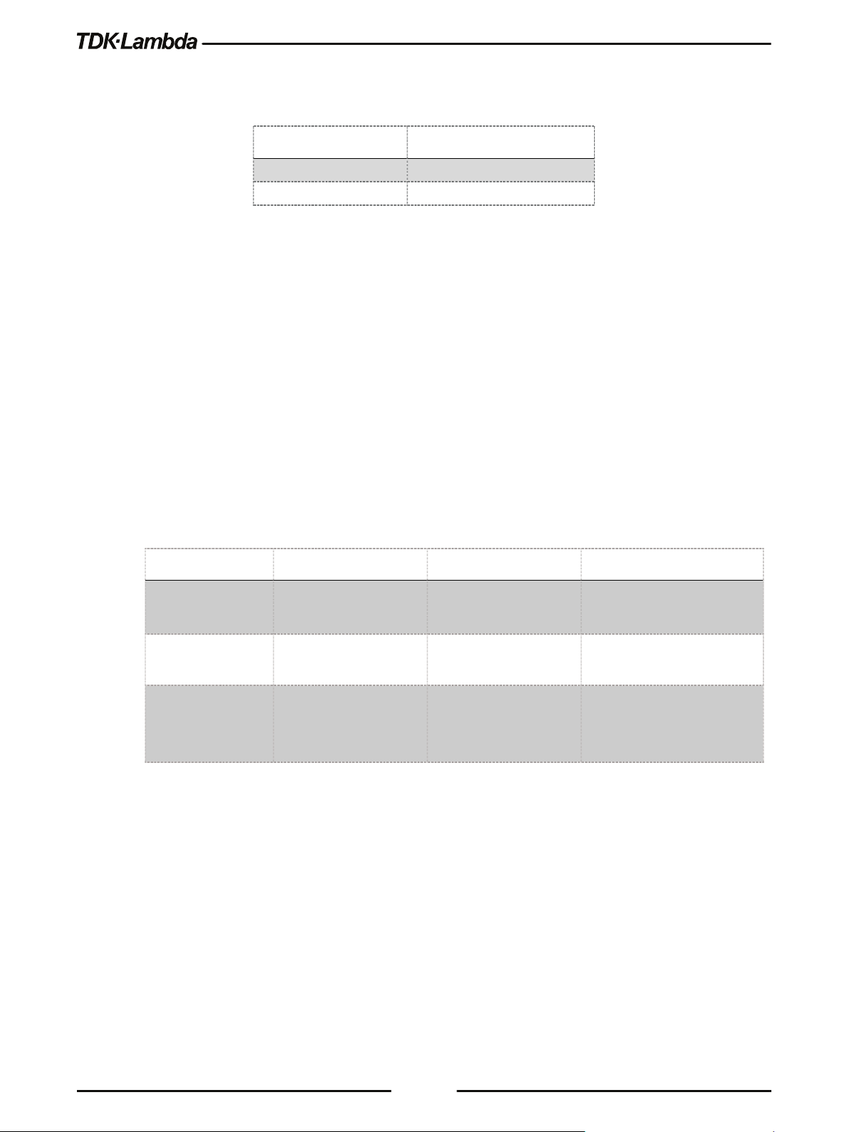
Model
Default Hostname
G10-40
G10-40
GH100-4.5
GH100-4P5
DHCP
Auto-IP
Static IP
Shows Host name on the Home
page and on the LAN Configure
If the rating has decimal point, substitute “P” for the decimal point.
For example:
A custom host name can be created through the web pages (refer to section 5.7.6.6).
For example, host name can be set to LAMBDA. In this case, the control program can send
commands to LAMBDA.
The Power Supply can detect if its host name is already in use by another device. This state is
called a host name conflict. In this case, the supply will make its host name unique by appending a
dash and a number (i.e. LAMBDA-2).
LAN Reset does not change the host name, even if it is a custom name, but it may remove the
dash and the number if a host name conflict has been removed.
To restore the factory default host name, open the LAN Modify web page and enter a blank for
the new host name (refer to section 5.7.6.6).
The Power Supply may be set to one of the three network modes, each with a different way to use
the host name. This is shown in the table below.
Hostname
Default Hostname
Hostname Protocol Hostname by NetBIOS or
Hostname on Web
Pages
xxxxvvvv-aaaa (Refer to
the above example)
DNS
Shows Host name on the
Home page and on the
LAN Configure page
5.7.4.6 Description and DNS Service Names
On the Power Supply web page, the Description field is also the DNS-SD service name.
The factory default description is:
< Manufacturer> <Product > < last 3 digits of serial number >
Example: TDK-LAMBDA Supply 123
xxxxvvvv-aaaa (Refer to
the above example)
Hostname by NetBIOS or
DNS
Shows Host name on the
Home page and on the
LAN Configure page
None, hostname cannot be
used
None, hostname cannot be
used
page
The Power Supply can detect if its service name (description) is already in use by another device.
This is called a service name conflict. In this case, the supply will change its service name to a
unique name by appending a number in brackets to it.
For example, its service name will become TDK-LAMBDA Supply 123 (2).
66
Page 75

A LAN Reset does not change the service name, even if it is a custom name, but it may remove the
dash and the number if a service name conflict has been removed.
To restore the factory default service name, open the LAN Modify web page and enter a blank
for the new service name (refer to section 5.7.6.6).
5.7.5 LAN Setup
5.7.5.1 View the IP and MAC Addresses
When the Power Supply is operating with the LAN enabled, the IP and MAC addresses may be
viewed on the front panel. To view the IP and MAC addresses, perform the following steps:
To view the IP address:
1. Press COMM button.
2. Rotate Voltage Encoder until IP appears on the Voltage display, 1 appears on the Current
display.
3. Press Current encoder to enter IP configuration. Rotate Voltage encoder to view the IP
address.
The voltage display shows IP1-IP4 by rotating Voltage encoder. The current display shows the
corresponding IP field.
To view the MAC address:
1. Press COMM button.
2. Rotate Voltage Encoder until MAC appears on the Voltage display, 1 appears on the Current
display.
3. Press Current encoder to enter MAC configuration. Rotate Voltage encoder to view the MAC
address.
The voltage display shows MAC1-MAC6 by rotating Voltage encoder. The current display shows
the corresponding MAC field.
5.7.5.2 Change the IP Address
The Power Supply allows changing all four numbers (octets) of the IP address via the front panel.
The IP address has four numbers (i.e. 10.97.4.4). Each number may be set to any value from 0 to
255.
NOTE
Some restrictions may apply due to subnet settings restrictions.
67
Page 76

To change the IP address:
IP address:
169.254.xxx.xxx
Subnet mask:
255.255.0.0
Default gateway
0.0.0.0
DNS Server
0.0.0.0
Hostname:
Refer to section 5.7.4.5
Description
Refer to section 5.7.4.6
Controller Access:
One Client Only
Ping Server:
Enabled
1. Press COMM button. Rotate Voltage Encoder until IP appears on the Voltage display, 1
appears on the Current display.
2. Press Current encoder to enter IP configuration. Rotate Voltage encoder to view the IP
address. Voltage display shows IP1-IP4 by rotating Voltage encoder. The Current display
shows the corresponding IP address.
3. Rotate Current encoder to change the IP address. Press Current encoder to acknowledge new
IP address.
4. If another device is using the same address, the Front Panel display and the rear LAN status
LED (Green) blinks. The address reverts to the previously set address.
5. Press any button or encoder to stop blinking.
NOTES
1. Modifying the IP address via the Front Panel, a command, or (LAN>Configure>Modify Page),
switches to STATIC IP addressing. (DHCP and Auto-IP addressing is disabled).
2. Refer to SYSTem[:COMMunicate]:LAN:IP <SRD> command to modify the IP address by
communication.
5.7.5.3 LAN Reset
To reset the Power Supply LAN settings to its factory settings, perform the following steps:
1. Press the COMM button.
2. Rotate Voltage Encoder until LAN appears on the Voltage display, RESET appears on the Current
display. Press Current encoder.
3. SURE appears on the Voltage display, NO appears on the Current display. Rotate current encoder
1 click clockwise. YES appears on the Current display.
4. Press Current encoder to reset LAN configuration to factory default settings.
The default LAN settings are:
• DHCP is enabled
• If DHCP fails to get a lease, the auto-IP settings will be obtained:
68
Page 77

Keep-Alive:
1800 Seconds (30 minutes)
Auto-Negotiate:
Automatically select network speed VXI-11
Discovery:
Enabled
Password:
None
Multicast DNS:
Enabled
5.7.6 Web Pages
5.7.6.1 Benefits of Web Pages
The web pages are useful for:
• Reading the Power Supply model, identity, revision and LAN setup information
• Configuring the LAN connection
• Programming and reading the Power Supply DC output
5.7.6.2 Opening the HOME Page
Once the rear panel green LAN Status LED turns ON, the web page is accessible.
1. Read the IP address from the front panel (Refer to section 5.7.5.1).
2. Open a web page browser program such as Internet Explorer. Enter the Power Supply IP
address as shown below.
3. Press the Enter key.
The Power Supply Home page appears. If it does not, refer to Troubleshooting section 10.6.
4. Alternately, the hostname may be used for addressing the web page as shown below (if the
Power Supply is set for DHCP/Auto-IP, and if a DNS naming service is running on the
computer). Refer to section 5.7.4.5 for a description of the hostname. Refer to the example
below.
5. The Power Supply Home page appears. If the home page does not appear, refer to
Troubleshooting section 10.6.
69
Page 78

5.7.6.3 The Home Page
The following page appears when the web page is opened for the first time or when it is refreshed:
Figure 5–9: Home Page
VISA Name Using IP Address
For automation programming, VISA is a type of communication driver.
For LAN instruments, the IP address may be used in the VISA resource descriptor. Refer to section
5.7.4.4.
VISA Name Using Hostname
An alternate VISA resource descriptor may be the hostname. Refer to section 5.7.4.5.
RS-485 Address
This address applies to a multi-drop chain of power supplies only.
The RS-485 address of the LAN supply is also called the Master Supply.
Hostname
A unique name for a device on a network. The default hostname is described in section 5.7.4.5.
It is configured as described in section 5.7.6.6.
Auto-MDIX
Power Supply LAN automatically detects if a patch or crossover LAN cable is used.
Auto-Negotiate
Power Supply LAN automatically adjusts its speed to the fastest speed available.
70
Page 79

Multicast DNS
The LAN broadcasts its hostname even if no network server is present. This is useful for
connecting over simple peer-to-peer networks.
Logging In
To change Power Supply output or LAN settings, a user must first log in.
When the DC Power tab or LAN tab is clicked, a login box appears:
1. Click the Login button at the bottom-left side of the web page. A windows appears (refer to the
screenshot below).
The only acceptable user name is “admin". By default, the password field is empty.
2. Click Login.
3. The password may be set or removed on the LAN -> Users web page.
4. LAN Reset clears the password.
5.7.6.4 Login Rules
• Up to 2 users may view the web pages of a Power Supply at the same time. However, the
update rate becomes slower as more web pages are open.
• Only one user at a time may be logged-in to modify the Power Supply settings.
• If an automation program with VISA or socket is running, user may view the web pages but
cannot login to change settings.
• If a user is logged in, a VISA or socket connection cannot be opened by an automation
program.
• A user may logout by clicking the Logout button, by closing the web browser or by leaving the
web browser idle for LAN Keep-alive seconds.
Figure 5–10: LOGIN Button
71
Page 80

5.7.6.5 DC Power Page
When the DC Power tab is selected, the following web page opens. This page and its sub-menus
allow a user to operate the Power Supply and adjust its output settings.
A. DC Power ➔ Output Page
When the DC Power tab is selected, the Output page opens by default (GUI).
Figure 5–11: Output Page
Refresh List
When this button is clicked, the web page scans to find connected Multi-drop power supplies and
adds the discovered addresses into the list box. This button applies to a multi-drop chain only as
described in section 5.7.1.1.
Click the Refresh List button after clicking the DC power button, after connecting or disconnecting a
Power Supply, or after changing the RS-485 address.
Select RS-485 Multi-drop Address
This address is described in section 5.7.1.1. This address applies to a multi-drop chain of RS-485
supplies only. If there is no multi-drop chain, only the address of the single LAN supply is available.
Blink Identify
When this button is clicked, the Master (LAN) Power Supply Front Panel display and the rear panel
green LAN status LED blinks.
In a multi-drop chain, only the master (LAN) Power Supply blinks. The blink identification is turned
OFF by clicking this button again or by clicking any button or encoder on the Power Supply Front
Panel or by SCPI command. login is not required to use this function.
Measurements
This section displays the selected Power Supply’s actual output Voltage, Current, operating mode
(constant-voltage, constant-current, constant power or off). Faults are shown in the voltage and
current display.
72
Page 81

Settings
This section displays the selected Power Supply’s output voltage, current limit and output ON/OFF
settings.
The settings cannot be changed until you have logged-in as 'admin'.
To change a settings, perform the following:
1. Tick Check to Modify.
2. Set desired settings. After settings are made, click Apply.
3. To view the actual settings, deselect Check to Modify. 0.
Faults
For the selected supply, these boxes show any fault which may be active in the supply.
B. DC Power ➔ Protection Page
On the DC Power tab, the Protection button is available at the top of the panel. When opened, the
window allows viewing and setting four protections.
• Over-Voltage Protection Limit
• Under-Voltage Limit
• Fold back Protection
• Auto-Start or Safe-Start
In a multi-drop chain, these settings affect only the supply selected in the RS-485 address list box.
The settings can be changed only by logging-in as 'admin'.
Figure 5–12: DC Power - Protection Tab
73
Page 82

C. DC Power ➔ System Page
On the DC Power tab, the System button is available at the top of the panel. When opened, the
window allows the user to operate four functions:
• Reset One Instrument (this resets only the supply selected in the RS-485 list box).
• Reset All Instruments (this resets all the supplies connected to the multi-drop bus).
• Save (saves the settings only for the supply selected in the RS- 485 list box).
• Recall (recalls the settings only for the supply selected in the RS-485 list box).
• The settings can be changed only by logging-in as 'admin'.
Figure 5–13: DC Power - System Tab
D. DC Power ➔ Utility Page
On the DC Power tab, the System button is available at the top of the panel. This page is used for
sending any SCPI command and viewing the response. It is a learning tool for SCPI language
operations. It allows operations, which are not available in the web pages.
Type any SCPI message in the top text box.
1. Click the Send and Read button.
2. For commands, there is no response.
3. For queries, the response appears in the middle text box.
4. You may read any System Error message by clicking the Read Errors button. The error
message (or 0,“No error”) appears in the bottom text box.
74
Page 83

5. To read system errors, send SYST:ERR:ENAB command to enable the error system (has to be
sent once prior reading errors). 0.
The settings can be changed only by logging-in as 'admin'.
5.7.6.6 LAN Page
When the LAN tab is selected, the following web page opens. This page and its sub-pages allow
you to view and configure the Power Supply’s LAN settings.
Figure 5–14: DC Power - Utility Tab
A. LAN ➔ Configure Page
When the LAN tab is selected, the Configure page opens:
The following settings are available on the LAN ➔ Configure web page:
• IP Address Source
Displays the way the IP address was selected. Options are DHCP/Auto-IP or Static IP.
• IP Address
Figure 5–15: LAN - Configure Tab
Displays the IP address assigned to the Power Supply through either DHCP, Auto-IP or Static
IP sources.
• Subnet Mask
Displays the subnet mask assigned to the Power Supply through either DHCP, Auto-IP or
Static IP.
• Default Gateway
75
Page 84

Address of the network router to allow the Power Supply to communicate outside of the local
subnet.
• DNS Server
Address of the server running the Domain Naming Service. This is used for hostname
addressing.
• Hostname
The Power Supply hostname may be used instead of the IP address to create a
communication link.
• Description
By default, this is “TDK-LAMBDA Supply <Last 3 digits of the Serial Number>”, but it may be
changed.
• Controller Access
The “One Client Only” setting is the default setting for the highest networking security. This
setting allows only one TCP socket to be open at a time, it disables the connectionless UDP
sockets. The multiple client setting is needed to allow more than one controller connection at a
time and to enable UDP sockets connections.
• Multicast DNS
mDNS is a protocol which allows devices on a network to advertise and use hostname
addressing even if no DNS server is connected. This service may be disabled for security
reasons or just to reduce network traffic.
• Modify
Click this button to open the window shown in the next section.
B. LAN ➔ Configure ➔ Modify Page
The Modify button on the LAN Configure page allows changing the LAN settings. The available
fields depend on the selection of DHCP Assigned / AUTO IP or Static IP. Changes to these setting
will take place only after clicking the Apply button.
The settings can be changed only by logging-in as 'admin'.
Figure 5–16: LAN – Changing Settings
76
Page 85

NOTE:
After changing the LAN settings, you are requested to close the web browser. Re-open the web
page. If the change duplicates IP, the LAN Status green LED and the Front Panel display will
blink, IP address will revert to the previous state. Press any Front Panel button or encoder to stop
the blinking.
NOTE:
You may be required to perform AC reset of the Power Supply after changing the LAN settings.
TCP/IP Mode
This selects how the Power Supply receives network settings. Select one of the following:
• DHCP Assigned / AUTO IP: This is the default mode. If this mode is selected, the network
server uses DHCP to assign the IP address, subnet mask, default gateway and DNS server.
Therefore, these fields are disabled (gray) on the web page. If the server cannot make the
assignment, the Power Supply reverts to the Auto IP method, described in section 5.7.4.4 on
page 65. In this mode, the user can change the hostname and description only.
The Hostname must not exceed 15 characters.
• Static IP: If this mode is selected, the IP address, subnet mask and default gateway must be
entered in the window fields. The settings must be compatible with the requirements of the
network server. These settings do not change if the Power Supply is transferred to a different
LAN connection.
DNS server field is disabled (gray).
In this mode, there is no hostname connectivity.
• Apply: Click this button to save the new settings. A pop-up dialog requests to close or refresh
the page. ‘admin’ log-in will be logged-out after refresh.
• Close: Click this button to return to the LAN Configure Page shown in section A.
NOTE:
NOTE:
77
Page 86

C. LAN ➔ Advanced & LAN->Advanced->Modify Page
Click the LAN ➔ Advanced button to view advanced LAN settings:
Figure 5–17: LAN – Advanced Tab
These settings can be changed only by logging-in as 'admin'.
Figure 5–18: LAN – Changing Settings
• LAN Timeout
If the user is logged in via the web page or by using VISA or TCP sockets, this is the time
duration (in seconds) in which the web pages may be inactive (idle) before the Power Supply
automatically logs out.
The default is 1800 seconds = 30 minutes.
• Ping Server
Ping is a network utility that allows the computer to verify communication with the Power
Supply. This service can be disabled on the Modify panel for security reasons.
• Auto-Negotiate
Shows the network speed at which the LAN card is allowed to operate. The choices are 100
Mbps, 10 Mbps (for slower networks) or Auto select.
• VXI-11 Discovery
This is a protocol, which allows the network server to detect which instruments are connected
to the LAN. It may be disabled for security reasons.
• Auto-MDIX
This service is always enabled in the Power Supply. The Power Supply LAN connection will
always detect a patch or cross-over cable automatically.
78
Page 87

• Apply
Click this button to save the new settings. A pop-up box will ask you to close or refresh the
page. ‘admin’ log-in will be logged-out.
• Close
Click this button to return to the LAN Configure Page shown in section A.
D. LAN ➔ Users Page
This page allows creating password protection for the web pages. There is no password protection
for automation programming with VISA or sockets.
By default, the old password is blank. The new password must contain between 6 and 16
characters. Password is case sensitive.
Reset Password
Once a password is applied, it may be changed by using the same screen, but it can only be
removed by performing the LAN Reset function.
5.7.6.7 HELP Page
A Help tab is available. This page is an Internet link to TDK-Lambda’s website pages.
Figure 5–19: LAN – Users Tab
Figure 5–20: Help Tab
79
Page 88

5.7.7 Programming Using VISA Drivers
5.7.7.1 VISA Description
In the test and measurement industry, Virtual Instrument Software Architecture (VISA) is a popular
framework that includes hardware drivers, configuration utilities and connection managers.
Varieties of communication busses are supported. VISA drivers are available from several
instrument vendors.
Any programming language that supports Windows COM or DLL libraries can call the VISA
functions.
5.7.7.2 VXI-11 Compatibility
VXI-11 is a protocol that allows communications between a computer port and an instrument. VISA
is built upon the VXI-11 specification. The Power Supply is compatible with the VXI-11
protocols:
• VXI–11 Device_link Open link to an instrument
• VXI–11 Device_write Write text to an instrument
• VXI–11 Device_read Read text from an instrument
• VXI–11 Destroy_link Close link to an instrument
5.7.7.3 Opening the VISA Connection
Test and automation programs may easily be written if they use the VISA libraries. The supported
VISA functions include Open, Read, Write and Close.
A VISA resource descriptor is used to describe a particular supply. For the Power Supply,
the descriptors are found on the supply’s Home web page. The VISA resource may use the
supply’s IP address or hostname.
Example
Format: TCPIP[board]::IP address/Host Name[::LAN device name][::INSTR]
[board] is the LAN card number, zero is optional
[::LAN device name] is by default “inst0”
[::INSTR] is optional
Examples:
TCPIP::10.225.26.60::inst0::INSTR
5.7.7.4 Communicating Using VISA
The VISA Write function sends SCPI commands to the Power Supply. The VISA read function
reads the response returned from the SCPI query.
of VISA resource descriptors are:
80
Page 89

One Client Only
Multiple Clients
You may view but cannot change the Power Supply operation.
Logged-in as “admin”
If you are logged in, any VISA, TCP or UDP connections are blocked.
VISA Connection
Only one VISA port may be open at a time.
TCP Socket
open. UDP sockets are blocked.
‘admin’ web page is open.
5.7.8 Programming Using Sockets
5.7.8.1 Socket Description
The VISA drivers for the Power Supply are commonly used in the Test and
Measurement industry. For customers who cannot use VISA because of installation, licensing
issues or because the controller (i.e.: industrial PLC) does not support VISA, the offers
socket connections. Socket is a low-level LAN protocol that is universally available in all operating
systems and programming environments.
5.7.8.2 Communicating Using Sockets
Communicating through sockets involves opening a socket connection, sending SCPI text
commands and reading the responses. The function by which a programming language manages
the socket is the TCP stack.
There are two types of socket protocols which may be used: TCP and UDP. Each has its own port
number, as described in sections 5.7.8.6 and 5.7.8.7.
5.7.8.3 Controller Access: Single and Multiple Clients
The web page has a security setting to limit or enable the types of connections and the numbers of
control computers (called “clients”) that may be connected at a time.
The single or multiple clients setting may be viewed on the LAN Configure Modify web page.
The performance of the
sockets are open at the same time. No more than two pages are open at the same time.
The rules for the One Client/Multiple Clients are:
Web Page Not logged-in Maximum of 2 copies of the web page may be open at any time.
Web Page
UDP Socket
NOTE:
LAN interface is impacted as more web pages, ports and
You cannot log in as ‘admin’ if a VISA or TCP socket port is already open.
One TCP socket may be open
if no VISA or ‘admin’ web page is
Multiple connections of TCP and UDP are
allowed to be open at a time, if no VISA or
81
Page 90

5.7.8.4 Input Buffer Requirements
Terminator Character (and ASCII hex)
Commands from the Controller
0x0A 0x0D
0x0D and 0x0A
With a controller using TCP or UDP sockets, the Power Supply can receive commands much faster
than it can process. To make sure the
controller sometimes sends a query and then waits for the response. The response is the
acknowledgement from the Power Supply
It is recommended that your controller routinely sends “SYST:ERR?”. This query takes 10 mSec,
and verifies that all commands have been accepted correctly.
When using sockets, it is recommended that no more than 20 SCPI commands may be sent
before a query is sent
5.7.8.5 Message Terminators
When using a program that sends separate SCPI commands through a TCP socket, the socket
drivers may combine all the messages into one long packet. Therefore, it is necessary to add a
terminator character to the end of each SCPI command.
LAN is not overloaded, it is required that the
that it has finished processing all commands.
NOTE
All SCPI commands must have a terminator character.
Responses from the All responses have Line-Feed and Carriage-return
5.7.8.6 Using TCP Sockets
This is the most commonly used socket type. It features a managed connection, message
acknowledgements, transmission error detection and correction.
Open TCP socket port 8003 to send SCPI commands.
Responses to queries are sent back automatically with a line-feed terminator and carriage return
appended.
If the web page LAN controller access is set to “Multiple Clients”, up to two controllers may open
TCP sockets to one Power Supply at the same time.
NOTE
One or more terminators required: Line-feed, Carriage-return
82
Page 91

5.7.8.7 Using UDP Sockets
This is a simpler socket type with reduced network traffic. It is a ‘connectionless’ protocol because
messages are sent and there is no acknowledgement that they have been received.
Open UDP socket port 8005 to send SCPI commands.
Responses to queries are sent back automatically with a line-feed terminator and carriage return
appended.
Before opening a UDP socket, it is required to open the web page and set the controller access to
Multiple Clients.
5.7.9 Connecting Over WAN
To connect over the Wide Area Network (i.e.: the global internet), the following settings must be
made in the network server.
5.7.9.1 View Web Pages Over WAN
The
is listening in Port 80.
Power Supply LAN interface has a server for running the web pages. The web server
The network administrator must obtain and assign a Global IP for the Power Supply. On the
network server, the network administrator also must ensure port 80 is exposed to WAN
connectivity.
5.7.9.2 Use Sockets Over WAN
The network administrator must obtain and assign a Global IP for the Power Supply. On the
network server, the network administrator also must ensure port 8003 (for TCP sockets) or port
8005 (for UDP sockets) is exposed to WAN connectivity.
83
Page 92

5.8
8 PIN CONNEC
TOR (IN)
8 PIN CONNE
CTOR (OUT)
Pin No.
Name
Pin No.
Name
Housing
Shield
Housing
Shield
8
SG 8 SG
3
TXD-
3
RXD-
6
TXD+
6
RXD+
4
RXD-
4
TXD-
5
RXD+
5
TXD+
IN
OUT
POWER SUPPLY
IN
OUT
POWER SUPPLY
IN
OUT
POWER SUPPLY
8
1
1
8
Multi Power Supply Connection (Daisy-Chain) to RS232, RS485, USB or LAN
A Daisy-chain configuration of up to 32 units can be connected to RS232, RS485, USB, LAN or
optional communication (i.e. IEEE). The first unit connects to the controller or PC via RS232,
RS485, USB, LAN or optional communication, while the RS485 bus connects the other units. The
user must set all Power Supplies in the chain to a unique address.
1. First unit connection: Select a communication Interface. Refer to section 5.2.2.
2. Other units’ connection: The other units on the bus are connected via RS485 interface. Refer
to Figure 5–21 for typical connections.
3. Using the Linking cable supplied with each unit (Refer to Figure 5–21), connect each unit’s
OUT connector to the next unit’s IN connector.
IN OUT
POWER SUPPLY
#0
#1
#2
Figure 5–21: Multi Power Supplies RS232/485, USB or LAN Connection
#31
NOTE:
If ten or more Power Supplies are connected in a Daisy-chain configuration, it is recommended to
connect 120Ω resistive termination at the last unit’s RS-485 OUT connector:
120Ω, 0.5W between TXD+ to TXD-.
120Ω, 0.5W between RXD+ to RXD-.
Table 5-2: Serial Link Cable with RJ-45 Shielded Connectors (P/N: GEN/RJ45)
84
Page 93

If a custom cable is used, connect only the pins listed in the table above. Keep pins 1, 2 and 7 not
connected.
When using multiple LAN controllers with Multi-drop, only one Power Supply may be “selected” at
a time because one controller may change the selected address and the others may not be aware
that a new address is active.
E. Set the Master Power Supply (First unit)
1. Set the Master Power Supply communication interface (RS232, RS485, USB, LAN or Optional
communication i.e. IEEE). Refer to section 5.2.2.
2. Set the supply’s RS-485 address as described below. Refer to section 5.2.3.
F. Set the Slave Power Supply (RS-485 units)
NOTE:
CAUTION
1. Set the Slave Power Supply communication interface to RS485. Refer to section 5.2.2.
2. Set the supply’s RS-485 address as described below. Refer to section 5.2.3.
G. Selecting One Power Supply in a Multi-drop Chain
All the SCPI commands may be sent to any one of the supplies in an RS-485 chain by first sending
the INSTrument:[N]SELect <NR1> address command.
All commands and queries will then apply only to the selected supply, until a new
INSTrument:[N]SELect <NR1> is sent.
After sending INSTrument:[N]SELect <NR1>, it is recommended to verify the command by sending
INSTrument:[N]SELect?, otherwise further commands may go to the wrong Power Supply.
H. Global Commands in a Multi-drop Chain
• The GLOBAL commands affect all of the supplies at the same time (Master and Slaves).
• There is no SYSTEM:ERROR? response message if one or more supplies cannot execute a
global command.
• There is no query version of these commands. Global settings must be queried by selecting
one Power Supply at a time and reading its setting.
• The global commands do not affect which Power Supply has been selected using the
INSTrument:[N]SELect <NR1> command. For example, if the following commands are sent:
INST:NSEL 4
VOLT 50
GLOB:VOLT 70
VOLT 90
85
Page 94

All the supplies on the multi-drop chain will be set to 70 volts, except for the supply at RS-485
address 4 that will be set to 90 volts.
RS-485 retransmit baud-rate is automatically set to 115,200 bps if USB, LAN or optional
communication (i.e. IEEE) is selected.
NOTE:
86
Page 95

5.9
GEN Protocol (GEN series communication language)
GEN communication language is supported to provide compatibility to the legacy GENESYS
Programmable Power Supplies Series. To use the advanced functions of the Power Supply, refer
to SCPI language, section 5.12.
Recommended time delay between commands: 5mSec minimum.
• The address (ADR n) command must return an ”OK” response before any other
command is accepted.
• GEN language is supported only in Serial communication interfaces (RS232, RS485 and
USB).
5.9.1 Data Format
Serial data format is 8 bit, one start bit and one stop bit.
NOTES:
No parity bit.
5.9.2 End of Message
The End of Message is the Carriage Return character (ASCII 13, 0x0D).
Power Supply ignores the Line Feed (ASCII 10, 0x0A) character.
5.9.3 Command Repeat
The backslash character ”\” causes the last command to be repeated.
5.9.4 Checksum
The user may optionally add a checksum to the end of the command. The checksum is ”$” followed
by two hex characters. If a command or a query has the checksum, the response will also have
one. There is no CR between the command string and the ”$” sign. Example: STT?$3A
STAT?$7B
5.9.5 Acknowledge
The Power Supply acknowledges the commands received by returning an ”OK” message. If an
error is detected, the Power Supply returns an error message. The rules for the checksum apply to
the Acknowledge feature as well.
5.9.6 Backspace
The backspace character (ASCII 8) clears the last character sent to the Power Supply.
5.10
GEN Command Set Description
5.10.1 General guides
• Any command or argument may be in capital letters or small letters.
87
Page 96

• In commands with an argument, a space must appear between the command and the
Data Formats
Description
significant digit. Example: 255
<NR2>
Digits with an explicit decimal point. Example: .0253
<NRh>
Digits in the hexadecimal format
TRUE.
limited number of values (i.e. RMT {LOC|REM|LLO})
Example: 29920Bits/V,00000Bits,3.3459E-05Volt/Bit,-0.0016Volts
argument.
• For any command that sets a numeric value, the value may be up to 12 characters long.
• Carriage Return: If the CR character (ASCII 13) is received by itself, the Power Supply will
respond with an ”OK” and CR.
5.10.2 Numeric / Data Type Parameters
<NR1> Digits with an implied decimal point assumed at the right of the least
<Bool> Boolean data. Examples: 0|1 or OFF|ON. Boolean parameters represent a
single binary condition that is either true or false. I.e. for a false condition,
the Power Supply will accept “OFF” or “0”. For a true condition, the Power
Supply will accept “ON” or “1” (OUT {OFF|ON}).
* Any number x which holds -0.5<x<0.5 is regarded as FALSE, otherwise
<DSC> DiSCrete. Discrete parameters are used to program settings that have a
<SRD> String Response Data. Predefined format of symbolic string parameters.
Table 5-3: Numeric / Data Type Parameters
5.10.3 Command Set Categories
The command set is divided into six categories as follows:
• Identification Commands
• Initialization Commands
• Global Output Commands
• Auxiliary Commands
• Status Commands
88
Page 97

no spaces)
Returns
<SRD>
Example
TDK-LAMBDA,G100-50
Query
Returns the software version as an ASCII string
Returns
<SRD>
Example
G:XX.XXX
Query
Returns the supply’s serial number. Up to 12 characters in any format
Returns
<SRD>
Example
111111-22222
Query
Returns the date of last calibration. Format: yyyy/mm/dd
Returns
<SRD>
Example
2017/12/17
Function
Clear Status. Sets FEVE and SEVE registers to zeroes
Returns
<DSC> OK
Function
Send ‘ADR’ and address (0 to 31) to open a communication channel.
Returns
Change mode by communication or AC recycle.
Parameters
0|1|2 or LOC|REM|LLO
Query
RMT?
Returns
<DSC> LOC|REM|LLO
5.10.4 Identification Commands
IDN?
Query Returns the Power Supply model identification as an ASCII string (one comma,
REV?
SN?
DATE?
5.10.5 Initialization Commands
CLS
ADR <NR1>
<DSC> OK
RMT <DSC>
Function Set the Power Supply control source (front panel or communication) to local,
remote or LLO mode.
Local – Enable front panel control.
Remote – Disable front panel settings change (settings preview only).
LLO – same as Remote + Disable front panel unlock function by front panel.
89
Page 98

Function
Reset setting. Refer to Table 3-5.
Returns
<DSC> OK
command
Returns
<DSC> OK
Function
Restore factory reset parameters. Refer to Table 3-5 & Table 3-6
Returns
None
Function
Set digital programming output voltage value in Volts
Table 5-4
Query
PV?
Returns
<NR2> 5-digits format
Query
Returns a measured output voltage
Returns
<NR2> 5 digits format
Function
Set digital programming output current value in Amperes
Parameters
Range is limited by the Power Supply model. Refer to Table 5-5.
Query
PC?
Returns
<NR2> 5-digits format
Query
Returns a measured output current
Returns
<NR2> 5 digits format
RST
\
Function Repeat last command. If \<CR> is received, the Power Supply will repeat the last
FRST
NOTE:
Factory Reset does not affect advanced parallel configuration acknowledgment (does not affect
power supply configuration (Single, Master or Slave roles does not change).
5.10.6 Output Commands
PV <NR2>
Parameters Range is limited by the Power Supply model, OVP and UVP settings. Refer to
MV?
PC <NR2>
MC?
90
Page 99

Query
Returns the measured output power
Returns
<NR2> 5 digits format
Under Voltage Set Point
Example
10.000, 10.000, 020.02, 010.00, 040.5, 000.0
POFF, SO) shutdown
Parameters
0|1, OFF|ON
Query
OTP?
Returns
<Bool> OFF|ON
CV Foldback protection
Parameters
0|1|2 or OFF|CC|CV
Query
FLD?
Returns
<DSC> OFF|CC|CV
Function
Sets the delay time from Foldback fault event to output disable
Parameters
0-255 (1=0.1sec). Value rounded to resolution 0.1
Query
FBD?
Returns
<NR1>
Function
MP?
DVC?
Query Displays Voltage and Current data. Data returns as a string of ASCII characters.
A comma separates different fields. Fields order: Measured Voltage, Programmed
Voltage, Measured Current, Programmed Current, Over Voltage Set Point and
OUT <Bool>
Function Enable / Disable Power Supply output. OUT ON will respond with ‘E07’ if the
output cannot be turned on because of a latching fault (OTP, AC, ENA, ILC,
FLD <DSC>
Function Sets the Foldback protection to OFF, CC or CV mode. “FLD 0/OFF” deactivates
Foldback protection. “FLD 1/CC” arms CC Foldback protection. “FLD 2/CV” arms
FBD <NR1>
FBDRST
Reset the added Fold Back Delay to default
91
Page 100

OVP <NR2>
response (‘E04’) and the OVP setting will stay unchanged
value. The OVP setting range is given in Table 5-6
Query
OVP?
Returns
<NR2> 4 digit format
Table 5-6
setting. Returns ‘E06’ if higher
Refer to Table 5-7 for UVL programming range
Query
UVL?
Returns
<NR2> 4 digit format
Function
Enable/Disable Under Voltage Protection
Parameters
0|1, OFF|ON
Query
UVP?
Returns
<Bool> OFF|ON
Function
Sets the auto-restart mode to ON or OFF
Parameters
0|1, OFF|ON
Query
AST?
Returns
<Bool> OFF|ON
Function
Saves the Power Supply settings to a specific memory location
memory location 1
2, 3 or 4), previously stored by the SAV command
the memory location 1
Function Sets the Over-Voltage Protection level. An attempt to adjust from the front
panel or program the OVP below this level will result in the execution error
Parameters Range is limited by the OVP programming range and voltage programmed
OVM
Function Sets the Over-Voltage Protection to maximum. The OVP setting range is given in
UVL <NR2>
Function Sets the Under Voltage Limit. Value ‘n’ may be equal or less than 95% of PV
Parameters Range is limited by the UVL programming range and voltage programmed value.
UVP <Bool>
AST<Bool>
SAV <NR1>
Parameters 1,2,3,4. SAV without a parameter stores the Power Supply settings in the
RCL <NR1>
Function Restores the Power Supply settings from a stored memory location (locations 1,
Parameters 1,2,3,4. RCL without a parameter restores the Power Supply settings stored in
92
 Loading...