

TDK-Lambda G20-250, GB80-65, G100-50, GB20-250, GB100-50 Safety & Installation Instruction
...Page 1

Series
Programmable DC Power Supplies
5kW in 1U 0-600V/ 0-500A
Built in LAN, USB, RS-232 & RS-485 Interface
Optional Interface: IEEE488.2 (GPIB)
SAFETY & INSTALLATION MANUAL
This Manual Covers Models:
G10-500
G80-65
GB10-500
GB80-65
G20-250
G100-50
GB20-250
GB100-50
G30-170
G150-34
GB30-170
GB150-34
G40-125
G300-17
GB40-125
GB300-17
G60-85
G600-8.5
GB60-85
GB600-8.5
Manual Supplements
The full user manual is available on TDK-Lambda website or can be ordered, refer to User manual IA761-04-02_.
IA761-04-01
Page 2

This page intentionally left blank
Page 3

TABLE OF CONTENTS
WARRANTY ................................................................................................................................................................... 1
SAFETY & EMC APPROVALS ........................................................................................................................................... 2
GENERAL SAFETY INSTRUCTIONS ................................................................................................................................... 4
ALLGEMEINE SICHERHEITSVORSCHRIFTEN ..................................................................................................................... 6
INSTRUCCIONES DE SEGURIDAD GENERALES ................................................................................................................. 8
CONSIGNES GÉNÉRALES DE SÉCURITÉ .......................................................................................................................... 10
ISTRUZIONI GENERALI DI SICUREZZA ........................................................................................................................... 12
INSTRUÇÕES GERAIS DE SEGURANÇA .......................................................................................................................... 14
PRODUCT SAFETY INSTRUCTIONS ................................................................................................................................ 16
CHAPTER 1: GENERAL INFORMATION .......................................................................................................................... 22
1.1 User Manual Content ................................................................................................. 22
1.2 Introduction ................................................................................................................ 22
1.2.1 General Description ....................................................................................... 22
1.2.2 Multiple Output Power System ..................................................................... 22
1.2.3 Control via LAN, USB or RS232/485 Communication Ports .......................... 22
1.2.4 Analog Voltage Programming and Monitoring ............................................. 23
1.2.5 Parallel Operation.......................................................................................... 23
1.2.6 Output Connections ...................................................................................... 23
1.2.7 Cooling and Mechanical Construction........................................................... 23
1.3 Accessories ................................................................................................................. 23
1.3.1 Accessories provided with the power supply ................................................ 23
1.3.1.1 Input connector protection, includes 3 parts: ............................................................ 23
1.3.1.2 AC Input Plug P/N: PC 5/ 4-STCL1-7, 62 (Phoenix contact) ......................................... 23
1.3.1.3 Output connector/ Bus bars protection ...................................................................... 23
1.3.1.4 Serial link cable ............................................................................................................ 23
1.3.1.5 Misc. Hardware ........................................................................................................... 24
1.3.1.6 Bus bars Screws kits .................................................................................................... 24
1.3.2
Optional accessories
.................................................................................. 24
1.3.2.1 Printed User Manuals
.............................................................................................. 24
1.3.2.2 Serial Port Cables
..................................................................................................... 24
1.3.2.3 Paralleling Cable .......................................................................................................... 24
1.3.2.4 AC Cables
................................................................................................................... 24
CHAPTER 2: FRONT/REAR PANEL CONTROLS AND CONNECTORS ................................................................................ 25
2.1 Introduction ................................................................................................................ 25
2.2 Front Panel Display and Controls
......................................................................... 25
2.3 Rear Panel Connectors
.......................................................................................... 27
CHAPTER 3: INSTALLATION .......................................................................................................................................... 29
3.1 General ....................................................................................................................... 29
3.2 Preparation for Use ..................................................................................................... 29
3.3 Initial Inspection ......................................................................................................... 30
3.4 Rack Mounting............................................................................................................ 30
3.4.1 Install the Power Supply in a Rack ................................................................. 30
3.4.2 Rack Mount Slides (Optional) ........................................................................ 31
3.5 Location, Mounting and Cooling ................................................................................ 31
3.6 AC Input Power Connection ....................................................................................... 32
3.6.1 AC Input Connector ....................................................................................... 34
Page 4

3.6.2 AC Input Wire Connection ............................................................................. 35
3.7 Turn-On Checkout Procedure
.............................................................................. 38
3.7.1 General .......................................................................................................... 38
3.7.2 Prior to Operation .......................................................................................... 38
3.7.3 Constant Voltage Check ................................................................................ 38
3.7.4 Constant Current Check ................................................................................ 39
3.8 Connecting the Load
.............................................................................................. 39
3.8.1 Load Wiring ................................................................................................... 40
3.8.2 Current Carrying Capacity ............................................................................. 40
3.8.3 Wire Termination .......................................................................................... 41
3.8.4
Noise and Impedance Effects
.................................................................... 41
3.8.5
Inductive Loads
........................................................................................... 42
3.8.6 Making the Load Connections ....................................................................... 42
3.8.7
Grounding Outputs
..................................................................................... 49
3.9 Local and Remote Sensing .......................................................................................... 50
3.9.1 Sense Wiring .................................................................................................. 50
3.9.2 Local Sensing ................................................................................................. 50
3.9.3 Remote Sensing ............................................................................................. 50
3.9.4 J8 Sense Connector Technical Information ................................................... 51
3.9.5 Repackaging for Shipment............................................................................. 51
Page 5

1
WARRANTY
This TDK-Lambda product is warranted against defects in materials and workmanship for a period of five years
from date of shipment. During the warranty period, TDK-Lambda will, at its option, either repair or replace
products, which prove to be defective.
Limitation of Warranty
The warranty shall not apply to defects resulting from improper or inadequate usage or maintenance by the buyer,
buyer supplied products or interfacing. The warranty shall not apply to defects resulting from unauthorized
modifications or from operation exceeding the environmental specifications of the product or if the QA seal has
been removed or altered by anyone other than TDK-Lambda authorised personnel. TDK-Lambda does not
warrant the buyers circuitry or malfunctions of TDK-Lambda products resulting from the buyer's circuitry.
Furthermore, TDK-Lambda does not warrant any damage occurring as a result of the buyer's circuitry or the
buyer's - supplied products. No other warranty is expressed or implied.
Warranty Service
This product must be returned to an authorized TDK-Lambda service facility for repairs or other warranty service.
For products returned to TDK-Lambda for warranty service, the buyer shall prepay shipping charges to TDKLambda and TDK-Lambda shall pay the shipping charges to return the product to the buyer. Refer section 3.9.5
for Repackaging for Shipment.
Disclaimer
The information contained in this document is subject to change without notice. TDK-Lambda shall not be liable
for errors contained in this document or for incidental or consequential damages in connection with the furnishing,
performance or use of this material. No part of this document may be photocopied, reproduced or translated into
another language without the prior written consent of TDK-Lambda.
Page 6

2
SAFETY & EMC APPROVALS
SAFETY
UL 60950-1 and CSA22.2 No.60950-1 - UL Listed. C-UL for Canada.
IEC 60950-1 - CB Report and Certificate.
EN 60950-1 - CE mark.
EMC
IEC 61204-3, EN 61204-3, FCC Part 15-A, VCCI-A
Marking by the CE Symbol indicates compliance to the LVD and EMC Directives of the European Union.
A “Declaration of Conformity” in accordance with the preceding directives and standards has been made and is
on file at our EU representative TDK LAMBDA UK, located at Kingsley Avenue, Ilfracombe, Devon EX34 8ES,
UK.
A “Declaration of Conformity” may be accessed via company web site www.uk.tdk-lambda.com/technical-data/
NOTE
EMC tests are applicable only to output signals and communication ports up to 3m length
and DC output ports up to 30m length.
REGULATORY NOTICES
FCC Notice
This device complies with Part 15 of the FCC Rules. Operation is subject to the following two conditions: (1) this
device may not cause harmful interference, and (2) this device must accept any interference received, including
interference that may cause undesired operation.
Page 7

3
NOTE
This equipment has been tested and found to comply with the limits for a Class A digital
device, pursuant to Part 15 of the FCC rules. These limits are designed to provide
reasonable protection against harmful interference when the equipment is operated in a
commercial environment. This equipment generates, uses, and can radiate radio
frequency energy and, if not installed and used in accordance with the instruction manual,
may cause harmful interference to radio communications.
Operation of this equipment in a residential area is likely to cause harmful interference in
which case the user will be required to correct the interference at his own expense.
WARNING
Modifications not expressly approved by the party responsible for compliance could void
the users authority to operate the equipment under FCC Rules.
CE Notice (European Union)
Marking of the CE symbol indicates compliance to the EMC Directive and the Low Voltage
Directive of the European Union. Such marking is indicative that the ™ series meets the following
technical standards:
• EN 60950-1: Information technology equipment - Safety - Part 1: General requirements.
• EN 61204-3: Low-Voltage switch mode power supplies – Part 3: Electromagnetic compatibility (EMC).
WARNING
This is a Class A product. On a domestic environment, this product may cause radio
interference in which case user may be required to take adequate measures.
WARNING
This is a product designed for an industrial environment. In a residential, commercial or
light industrial environment it may cause radio interference. The user may be required to
take adequate measures to reduce interference.
Page 8

4
GENERAL SAFETY INSTRUCTIONS
READ SAFETY INSTRUCTIONS
The following safety precaution must be observed during all phases of operation, service and repair of this
equipment. Failure to comply with the safety precautions or warnings in this document violates safety
standards of design, manufacture and intended use of this equipment and may impair the built-in
protections within. TDK-Lambda shall not be liable for user’s failure to comply with these requirements.
SERVICING:
These products are not customer serviceable. Parts substitutions and modifications are by authorized
TDK-Lambda service personnel only. For repairs or modifications, the product must be returned to TDKLambda service facility.
CRITICAL COMPONENTS:
These products are not authorised for use as critical components in nuclear control systems, life support
systems or equipment for use in hazardous environments without the express written approval of the
Managing Director of TDK-Lambda Ltd.
PRODUCT USAGE:
These products are designed for use as standalone equipment within a limits described in product Manual.
ENVIRONMENTAL:
These products are IP20, and therefore chemicals/solvents, cleaning agents and other liquids must not be
used.
ENVIRONMENT:
These products are designed for use within a Pollution Degree 2, Overvoltage Category II environment.
OUTPUT LOADING:
The output power taken from the products must not exceed the rating stated on the product label, except
as stated in the product Manual.
INPUT PARAMETERS:
These products must be operated within the input parameters stated in the product Manual.
END OF LIFE DISPOSAL:
The products contains components that require special disposal. Make sure that the unit is properly
disposed of at the end of its service life and in accordance with local regulations.
Page 9

5
RISK OF ELECTRIC SHOCK
High Voltage Warning: Dangerous voltages are present within the power supply. To avoid injuries,
always disconnect power, discharge circuits and remove external voltage sources before touching
components.
Class I Warning: The unit is Class I product. To minimize electrical shock hazard, the unit must be reliably
earthed and professionally installed. Any interruption of the protective ground conductor or disconnection
of the protective earth terminal will cause a potential shock hazard that might cause personal injury.
Energy Hazards Warning: The main output of the unit is hazardous energy (240VA) and must not be
user accessible in the end application.
Hazardous output Warning: There is a potential shock hazard when using a power supply with an output
voltage greater than 60VDC. Do not turn ON power supply when output voltage is above 60VDC without
output bus-bars/or output connectors protection assembled. Turn OFF power supply or disconnect power
supply from AC mains before making or changing any rear panel connection.
Internal fuse Caution: Internal fuse protect the unit and must not be replaced by the user. In case of
internal defect, the unit must be returned to TDK-Lambda Ltd. or one of their authorised agents.
OTHER
The ventilation openings on these products must not be impeded. Ensure that there is at least 50mm
spacing between any obstruction and the ventilation openings.
Page 10

6
ALLGEMEINE SICHERHEITSVORSCHRIFTEN
LESEN SIE DIE SICHERHEITSVORSCHRIFTEN
Die folgenden Sicherheitsvorschriften müssen in allen Phasen des Betriebs, der Wartung und der
Reparatur der Anlage eingehalten werden. Eine Missachtung der Sicherheitsvorschriften und
Warnhinweise aus diesem Handbuch führt zur Verletzung der bestehenden Sicherheitsstandards für
Design, Produktion und der zweckbestimmten Verwendung der Anlage und kann die integrierten
Schutzvorrichtungen beschädigen.
TDK-Lambda ist nicht für Schäden haftbar, die durch Missachtung dieser Sicherheitsvorschriften
durch den Benutzer entstehen können.
WARTUNG:
Diese Produkte können nicht durch den Kunden gewartet werden. Ersatzteilaustausch und Modifikationen
dürfen nur durch von TDK-Lambda zugelassenes Personal durchgeführt werden. Für Reparaturen oder
Modifikationen muss das Gerät an einen Vertriebspartner von TDK- Lambda geschickt werden.
KRITISCHE KOMPONENTEN:
Diese Produkte sind nicht für die Verwendung als kritische Komponenten in nuklearen Kontrollsystemen,
Lebenserhaltungssystemen oder Geräten in gefährlichen Umgebungen geeignet, sofern dies nicht
ausdrücklich und in Schriftform durch den Geschäftsführer von TDK- Lambda Ltd. genehmigt wurde.
PRODUKTVERWENDUNG:
Diese Produkte sind für den Einsatz als Standalone-Geräte innerhalb der im Produkthandbuch
beschriebenen Grenzen konzipiert.
UMWELT:
Diese Produkte besitzen die Schutzklasse IP20. Aus diesem Grund dürfen keine
Chemikalien/Lösungsmittel, Reinigungsmittel und andere Flüssigkeiten verwendet werden.
UMGEBUNG:
Diese Produkte sind für den Einsatz in einer Umgebung mit Verschmutzungsgrad 2,
Überspannungskategorie II, konzipiert.
AUSGANGSSTROM:
Der Ausgangsstrom des Produktes darf die Leistung, die auf dem Label des Produktes vermerkt ist, nur
dann überschreiten, wenn dies in den Produktgrenzen dieses Handbuches ausgezeichnet ist.
EINGANGSPARAMETER:
Dieses Produkt muss innerhalb der Eingangsparameter betrieben werden, die im Produkthandbuch
angegeben sind.
ENTSORGUNG AM ENDE DER BETRIEBSZEIT:
Die Produkte enthalten Komponenten, die unter Sondermüll fallen. Das Gerät muss am Ende der
Betriebszeit ordnungsgemäß und in Übereinstimmung mit den regionalen Bestimmungen entsorgt werden.
Page 11

7
GEFAHR VON ELEKTRISCHEM SCHLAG
Hochspannungswarnung: Innerhalb des Netzteiles gibt es gefährliche Spannungen. Um
Personenschäden zu vermeiden, muss vor dem Kontakt mit dem Gerät immer die Stromversorgung
unterbrochen, die Stromkreise entladen und externe Spannungsquellen entfernt werden.
Schutzklasse I Warnung: Das Gerät ist ein Produkt der Schutzklasse 1. Zur Vermeidung gefährlicher
Energieinhalte und Spannungen, ist das Gerät an eine zuverlässige Schutzerde anzuschließen und durch
Fachleute zu installieren. Jede Unterbrechung des PE-Leiters oder die Trennung der PE-Verbindung kann
einen möglichen elektrischen Schlag hervorrufen, der Personenschäden zur Folge haben kann.
Warnung vor Stromschlaggefahr: Der Hauptausgang dieses Gerätes steht unter gefährlicher Spannung
(240 V) und darf im Endgerät, in das es installiert wird, nicht für den Benutzer zugänglich sein.
Warnung vor gefährlichem Ausgang: Es besteht Stromschlaggefahr, wenn eine Stromversorgung mit
einer Ausgangsspannung von mehr als 60 V Gleichspannung verwendet wird. Schalten Sie die
Stromversorgung nicht EIN, falls die Ausgangsspannung über 60 V Gleichspannung liegt, wenn die
Schutzabdeckungen der Stromschienen oder Ausgangsklemmen nicht montiert sind. Schalten Sie die
Stromversorgung AUS oder trennen Sie diese von der Netzversorgung, bevor Sie den rückwärtigen
Anschluss verbinden oder verändern.
Warnung - Interne Sicherung: Interne Sicherungen schützen das Gerät und dürfen durch den Benutzer
nicht ausgetauscht werden. Im Fall von internen Defekten muss das Gerät an TDK- Lambda Ltd. oder
einen der autorisierten Vertriebshändler zurückgeschickt werden.
WEITERES
Die Belüftungsöffnungen an diesem Produkt dürfen nicht blockiert werden. Achten Sie darauf, dass
mindestens 50 mm Abstand zwischen Hindernissen und den Belüftungsöffnungen bleibt.
Page 12

8
INSTRUCCIONES DE SEGURIDAD GENERALES
LEER LAS INSTRUCCIONES DE SEGURIDAD
La siguiente precaución de seguridad debe ser respetada durante todas las fases de funcionamiento,
mantenimiento y reparación de este equipo. El incumplimiento de las precauciones o advertencias de
seguridad recogidas en este documento infringe las normativas de seguridad de diseño, fabricación y uso
previsto de este equipo y puede afectar a las protecciones incorporadas en el mismo. TDK-Lambda no
asumirá responsabilidad alguna si el usuario no cumple estos requisitos.
MANTENIMIENTO:
El cliente no debe realizar el mantenimiento de estos productos. Solo el personal de servicio autorizado
de TDK-Lambda sustituirá y modificará las piezas. Para cualquier reparación o modificación del producto,
este debe ser enviado a un centro de servicio de TDK-Lambda.
COMPONENTES FUNDAMENTALES:
El uso de estos productos como componentes fundamentales en sistemas de control nuclear, sistemas de
soporte vital o equipos para el uso en entornos peligrosos queda prohibido sin el consentimiento expreso
por escrito del Director General de TDK-Lambda Ltd.
USO DE PRODUCTOS:
Estos productos han sido diseñados para utilizarse como equipo individual dentro de los límites descritos
en el manual del producto.
ECOLÓGICOS:
Estos productos son IP20, por lo que no deben utilizarse productos químicos/disolventes, productos de
limpieza ni otros líquidos.
MEDIO AMBIENTE:
Estos productos han sido diseñados para utilizarse dentro de un entorno con un nivel de contaminación 2
y categoría de sobretensión II.
CARGA DE SALIDA:
La potencia de salida extraída de los productos no debe exceder la potencia de servicio indicada en la
etiqueta del producto, con excepción de lo indicado en el manual del producto.
PARÁMETROS DE ENTRADA:
Estos productos deben utilizarse dentro de los parámetros de entrada indicados en el manual del
producto.
ELIMINACIÓN AL FINAL DE LA VIDA ÚTIL:
Los productos contienen componentes que deben eliminarse de forma especial. Asegurarse de que la
unidad se elimina de forma adecuada al final de su vida útil y de conformidad con las normas locales.
Page 13

9
RIESGO DE DESCARGAS ELÉCTRICAS
Advertencia sobre la alta tensión: existen tensiones peligrosas dentro de la fuente de alimentación.
Para evitar lesiones, desenchufe siempre el cable de alimentación, descargue los circuitos y desconecte
las fuentes de tensión externas antes de tocar los componentes.
Advertencia sobre la Clase I: la unidad es un producto de Clase I. Para minimizar el riesgo de
descargas eléctricas, la unidad debe conectarse a tierra de forma fiable e instalarse de forma profesional.
Cualquier interrupción del conductor de tierra de protección o desconexión del borne de tierra de
protección supondrá un riesgo potencial de descarga eléctrica que puede llegar a causar daños
personales.
Advertencia sobre los peligros de la energía: la salida principal de la unidad es energía peligrosa (240
VA) y no debe ser accesible a los usuarios en el equipo final.
Advertencia sobre la salida peligrosa: existe un peligro de descargas potencial cuando se utiliza una
fuente de alimentación con una tensión de salida superior a 60 V CC. No ENCENDER la fuente de
alimentación cuando la tensión de salida supere los 60 V CC sin tener montados tubos de conducción de
corriente de salida o conectores de salida. APAGAR la fuente de alimentación o desconectar la fuente de
alimentación de la red eléctrica CA antes de realizar o cambiar cualquier conexión del panel posterior.
Precaución sobre el fusible interno: el fusible interno protege la unidad y no debe ser sustituido por el
usuario. En caso de defecto interno, la unidad deberá enviarse a TDK-Lambda Ltd. o a alguno de sus
agentes autorizados.
INFORMACIÓN ADICIONAL
No deben obstruirse las aberturas de estos productos. Asegurarse de que hay un mínimo de 50 mm de
espacio entre cualquier obstrucción y las aberturas de ventilación.
Page 14

10
CONSIGNES GÉNÉRALES DE SÉCURITÉ
LISEZ LES CONSIGNES DE SÉCURITÉ
Respectez les consignes de sécurité suivantes pendant toutes les phases d'utilisation, d'entretien et de
réparation de cet équipement. Le non-respect des consignes de sécurité et des avertissements figurant
dans ce document enfreindrait les normes de sécurité relatives à la conception, à la fabrication et à l'usage
prévu de cet équipement. Il risquerait également d'en compromettre les protections incorporées. TDKLambda décline toute responsabilité en cas de non-respect de ces impératifs de sécurité.
ENTRETIEN:
ces produits n'ont pas été conçus pour être entretenus par le client. Les substitutions et modifications de
pièces doivent impérativement être réalisées par un technicien d'entretien agréé par TDK Lambda. Pour
les réparations ou les modifications, renvoyez le produit au centre d'entretien TDK Lambda.
COMPOSANTS CRITIQUES:
ces produits n'ont pas été conçus pour être utilisés comme composants critiques de systèmes de
commande nucléaire, de survie ou d’équipements utilisés dans des environnements dangereux, sans
l'autorisation écrite expresse du directeur général de TDK-Lambda Ltd.
UTILISATION DU PRODUIT:
ces produits ont été conçus pour être utilisés de manière autonome, conformément aux limites indiquées
dans le Manuel y afférent.
CONSIDÉRATIONS ENVIRONNEMENTALES:
ces produits étant conformes à la norme de protection IP20, ils ne doivent pas être utilisés avec les
produits chimiques/solvants, agents de nettoyage et autres liquides.
ENVIRONNEMENT:
ces produits sont compatibles avec une utilisation dans un milieu soumis à un Degré 2 de pollution,
Catégorie de surtension II.
CHARGE DE SORTIE:
la puissance de sortie de ces produits ne doit pas dépasser la valeur indiquée sur leur étiquette, autrement
que dans les conditions rappelées dans le Manuel y afférent.
PARAMÈTRES D'ENTRÉE:
ces produits doivent être utilisés avec les paramètres d'entrée indiqués dans leurs Manuels.
MISE AU REBUT EN FIN DE VIE:
ces produits contiennent des composants à soumettre à une procédure de mise au rebut particulière.
Veillez à ce que la mise au rebut de ces appareils en fin de vie utile s'effectue en bonne et due forme,
conformément à la réglementation en vigueur sur place.
Page 15

11
RISQUE DE CHOC ÉLECTRIQUE
Avertissement de haute tension: l'alimentation de ces appareils est parcourue par des tensions
dangereuses. Pour éviter les blessures, débranchez toujours l'alimentation, déchargez les circuits et
retirez les sources de tension extérieures avant de toucher les composants.
Avertissement de Classe I: l'appareil est un produit de Classe I. Pour réduire au minimum le risque de
choc électrique, l'appareil doit être relié à la terre et installé par un professionnel. Toute rupture du
conducteur de terre ou de la borne de raccordement à la terre de l'appareil, présenterait un risque de choc
électrique susceptible de provoquer des blessures.
Avertissement de danger électrique: l'appareil servant principalement à la production d'électricité
dangereuse (240 VA), il ne doit pas être accessible par l'utilisateur dans son application finale.
Avertissement de sortie dangereuse: l'utilisation d'une alimentation dont la tension de sortie dépasse 60
V c.c. présente un risque de choc électrique. Ne mettez pas l'alimentation sous tension lorsque la tension
de sortie est supérieure à 60 V c.c., avant d'avoir monté des bus- barres ou des connecteurs de sortie.
Éteignez l'alimentation ou débranchez-la de l'alimentation secteur avant d'effectuer ou de changer les
branchements au panneau arrière.
Précaution relative au coupe-circuit interne: un fusible interne protège l'appareil et ne doit pas être
remplacé par l'utilisateur. En cas de défaut interne, renvoyez l'appareil à TDK-Lambda Ltd. ou à l'un de
ses agents agréés.
AUTRE
Les ouïes d'aération de ces produits doivent être libres de toute entrave. Veuillez à prévoir au moins 50
mm d'espace libre entre une obstruction quelconque et les ouïes d'aération de ces appareils.
Page 16

12
ISTRUZIONI GENERALI DI SICUREZZA
LEGGERE LE ISTRUZIONI DI SICUREZZA
È necessario attenersi alle seguenti precauzioni di sicurezza, a tutti gli stadi del funzionamento, della
manutenzione e della riparazione dell’apparecchiatura. Il mancato rispetto delle precauzioni di sicurezza o
delle avvertenze contenute nel presente documento costituisce una violazione degli standard di sicurezza
relativi alla progettazione, fabbricazione e uso previsto dell’apparecchiatura, e potrebbe compromettere le
protezioni interne di quest’ultima. TDK-Lambda non sarà responsabile per l’inosservanza di tali requisiti da
parte dell’utente.
MANUTENZIONE:
Questi prodotti non possono essere sottoposti a manutenzione da parte del cliente. Qualunque
sostituzione o modifica dei componenti deve essere affidata esclusivamente al personale di manutenzione
di TDK-Lambda. Per eventuali riparazioni o modifiche, il prodotto deve essere inviato al centro assistenza
di TDK-Lambda.
COMPONENTI CRITICI:
L’uso di questi prodotti come componenti critici non è autorizzato all’interno di sistemi di controllo nucleari,
sistemi salvavita o apparecchiature destinate all’impiego in ambienti pericolosi, senza l’esplicito consenso
scritto dell’Amministratore delegato di TDK-Lambda Ltd.
USO DEI PRODOTTI:
Questi prodotti sono destinati all’uso come apparecchiature autonome, entro i limiti indicati nel loro
Manuale.
PRECAUZIONI AMBIENTALI:
Questi sono prodotti IP20, pertanto l’utente non deve utilizzare agenti chimici/solventi, agenti per la pulizia
e altri liquidi.
CONDIZIONI AMBIENTE:
Questi prodotti sono concepiti per l’uso in ambienti con Grado di inquinamento 2, Categoria di
sovratensione II.
CARICO DI USCITA:
La potenza di uscita dai prodotti non deve superare il livello nominale riportato sulla loro etichetta, salvo
quanto specificato nel Manuale dei prodotti.
PARAMETRI D’INGRESSO:
Il funzionamento di questi prodotti deve rientrare nei parametri d’ingresso riportati nel loro Manuale.
SMALTIMENTO AL TERMINE DELLA VITA UTILE:
I prodotti contengono componenti che è necessario smaltire in modo speciale. Accertarsi di smaltirli
correttamente al termine della loro vita utile e nel rispetto delle norme locali vigenti.
Page 17

13
RISCHIO DI SCOSSA ELETTRICA
Avvertenza - alta tensione: All’interno dell’alimentatore sono presenti tensioni pericolose. A prevenzione
del rischio di infortuni, scollegare sempre le unità dalla rete elettrica, scaricare i circuiti ed eliminare le fonti
esterne di tensione prima di toccare i componenti.
Avvertenza - prodotto di Classe I: L’unità è un prodotto di Classe I. Per ridurre al minimo il rischio di
scossa elettrica, l’unità deve essere messa a terra e installata in modo professionale e affidabile. In caso
di interruzione del conduttore protettivo di terra, o scollegamento del terminale protettivo di terra, vi sarà un
rischio di scossa elettrica e conseguenti infortuni alla persona.
Avvertenza - rischi elettrici: L’uscita principale di questa unità è energia pericolosa (240 VA) e non deve
essere accessibile da parte dell’utente nell’ambito dell’applicazione finale.
Avvertenza - uscita pericolosa: Vi è un potenziale rischio di scossa elettrica con l’uso di alimentatori la
cui tensione in uscita superi 60 V CC. Non ACCENDERE l’alimentatore quando la tensione in uscita è
superiore a 60 V CC in assenza di protezioni con sbarre collettrici o connettori di uscita. SPEGNERE
l’alimentatore o staccarlo dalla presa elettrica a CA prima di eseguire o modificare qualsiasi collegamento
sul pannello posteriore.
Precauzione - fusibile interno: Il fusibile interno protegge l’unità e non deve essere sostituito dall’utente.
Nell’eventualità di un difetto interno, l’unità deve essere inviata a TDK-Lambda Ltd. o a un suo agente
autorizzato.
ALTRO
Le aperture di ventilazione su questi prodotti non devono essere ostruite. Controllare che vi sia una
distanza minima di 50 mm fra le aperture di ventilazione e qualsiasi eventuale ostruzione.
Page 18

14
INSTRUÇÕES GERAIS DE SEGURANÇA
LEIA AS INSTRUÇÕES DE SEGURANÇA
As seguintes precauções de segurança devem ser respeitadas em todas as fases de funcionamento,
manutenção e reparação deste equipamento. A não observância dos avisos e precauções de segurança
constantes neste documento viola os padrões de segurança da concepção, fabrico e utilização pretendida
deste equipamento, podendo danificar as protecções integradas no seu interior. A TDK-Lambda não
poderá ser responsabilizada pelo não cumprimento destes requisitos por parte do utilizador.
MANUTENÇÃO:
Estes produtos não são podem ser submetidos a manutenção por parte do cliente. As modificações e
substituições de peças devem ser realizadas apenas pelo pessoal de assistência autorizado da TDKLambda. Para a realização de reparações ou modificações, é necessário devolver o produto a uma
unidade de serviço da TDK-Lambda.
COMPONENTES ESSENCIAIS:
Não é autorizada a utilização destes produtos como componentes essenciais de sistemas de controlo
nuclear, sistemas de suporte de vida ou equipamento para utilização em ambientes perigosos sem a
expressa autorização por escrito do Director-Geral da TDK-Lambda Ltd.
UTILIZAÇÃO DO PRODUTO:
Estes produtos foram concebidos para utilização como equipamento autónomo, dentro dos limites
descritos no manual do produto.
AMBIENTAL:
Estes produtos são IP20 e, como tal, não se devem utilizar químicos/solventes, agentes de limpeza e
outros líquidos.
AMBIENTE:
Estes produtos foram concebidos para utilização em ambientes da categoria de sobretensão II, com um
Nível de Poluição 2.
CARGA DE SAÍDA:
A potência de saída extraída dos produtos não deve exceder a classificação assinalada na etiqueta do
produto, excepto quando indicado no manual do produto.
PARÂMETROS DE ENTRADA:
Estes produtos devem ser utilizados dentro dos parâmetros de entrada indicados no manual do produto.
ELIMINAÇÃO NO FIM DE VIDA:
Os produtos contêm componentes que necessitam de procedimentos especiais de eliminação. Certifiquese de que a unidade é devidamente eliminada no fim da sua vida útil e que tal é feito em conformidade
com os regulamentos locais.
Page 19

15
RISCO DE CHOQUE ELÉCTRICO
Aviso de alta tensão: Estão presentes tensões perigosas dentro da fonte de alimentação. Para evitar
ferimentos, desligue sempre a energia, descarregue os circuitos e retire as fontes de tensão externas
antes de tocar nos componentes.
Aviso de classe I: A unidade é um produto de Classe I. Para reduzir o risco de choque eléctrico, a
unidade deve ser ligada à terra de forma fiável e instalada por um profissional. Qualquer interrupção do
condutor de terra de protecção ou corte do terminal de terra de protecção poderá originar um risco de
choque passível de provocar ferimentos.
Aviso de perigos de energia: A saída principal da unidade constitui energia perigosa (240 V AC) e não
deve estar acessível ao utilizador na aplicação final.
Aviso de saída perigosa: Há a possibilidade de existir risco de choque ao utilizar uma fonte de
alimentação com tensão de saída superior a 60 V CC. Não LIGUE a fonte de alimentação quando a
tensão de saída for superior a 60 V CC e não existir protecção para as barras do bus de saída/conectores
de saída. DESLIGUE a fonte de alimentação ou interrompa a ligação entre a fonte de alimentação e a
corrente alternada antes de realizar ou alterar qualquer ligação no painel traseiro.
Cuidados com o fusível interno: O fusível interno protege a unidade e não deve ser substituído pelo
utilizador. Em caso de defeito interno, a unidade deve ser devolvida à TDK-Lambda Ltd. ou a um dos seus
agentes autorizados.
OUTROS
As aberturas de ventilação destes produtos não devem ser obstruídas. Certifique-se de que existe um
espaçamento de pelo menos 50 mm entre qualquer obstrução e as aberturas de ventilação.
Page 20

16
PRODUCT SAFETY INSTRUCTIONS
CAUTION
The following safety precautions must be followed during all phases of operation, service,
and repair of this equipment. Failure to comply with the safety precautions or warnings in
this document violates safety standards of design, manufacture and intended use of this
equipment and may impair the built-in protections within. TDK-Lambda shall not be liable
for user’s failure to comply with these requirements.
VORSICHT
Die folgenden Sicherheitsvorschriften müssen vor Inbetriebnahme und in jeglichem
Betriebszustand bei Wartungsarbeiten oder Reparatur dieses Geräts beachtet werden.
Eine Missachtung der Sicherheitsvorschriften und Warnhinweise aus diesem Handbuch
stellt eine Verletzung der Sicherheitsstandards für Design, Herstellung und vorgesehene
Benutzung dieses Geräts dar und kann die im Gerät integrierten Schutzfunktionen
beeinträchtigen. TDK-Lambda ist nicht haftbar, wenn der Benutzer diese Anforderungen
missachtet.
OVERVOLTAGE CATEGORY AND ENVIRONMENTAL CONDITIONS
The ™ series units have been assigned to Overvoltage category II.
The ™ series units are intended for use in the following operation conditions:
• Indoor use
• Pollution degree 2
• Max. operational altitude: 3000m above sea level (Refer to product Spec. for operating
conditions).
• Ambient temperature: 0°C-50°C.
ÜBERSPANNUNGSKATEGORIE UND UMWELTBEDINGUNGEN
Die Geräte der
™ Serie wurden der Überspannungskategorie II zugeordnet.
Die Geräte der
™ Serie sind zur Benutzung unter folgenden Betriebsbedingungen
vorgesehen:
•
Benutzung in Innenräumen
•
Verschmutzungsgrad 2
• Maximale Einsatzhöhe: 3000 m über Null (siehe Produktspezifikationen für Betriebsbedingungen).
• Umgebungstemperatur: 0 °C – 50 °C.
Page 21

17
GROUNDING
This product is a Safety Class1 instrument. To minimize shock hazard, the instrument chassis must be
connected to an electrical ground. The instrument must be connected to the AC power supply mains
through a four conductor power cable with the ground wire firmly connected to an electrical ground
(safety ground) at the power outlet.
For instruments designed to be hard-wired to the supply mains, the protective earth terminal must be
connected to the safety electrical ground before another connection is made. Any interruption of the
protective ground conductor, or disconnection of the protective earth terminal will cause a potential
shock hazard. That might cause personal injury.
ERDUNG
Bei diesem Produkt handelt es sich um ein Gerät der Schutzklasse 1. Damit gefährliche Energieinhalte
und Spannungen vermieden werden, ist das Gehäuse des Gerätes an eine Schutzerde
anzuschliessen. Das Gerät muss mit Hilfe eines genormten 4-adrigen Kabels (L1, L2,L3, PE) fest an
eine 3-Phasige AC-Versorgung angeschlossen werden. Der PE-Anschluss ist an die vorgesehene
Schutzerde anzuschliessen.
Bei der Festverdrahtung des Gerätes ist sicherzustellen, dass der PE-Anschluss als erstes verbunden
wird.
Jede mögliche Unterbrechung des PE-Leiters oder Trennung der PE-Masse kann einen möglichen
elektrischen Schlag hervorrufen, der einen Personenschaden zur Folge hätte.
LIVE CIRCUITS
Operating personnel must not remove the instrument cover.
No internal adjustment or component replacement is allowed by non-TDK-Lambda qualified service
personnel. Never replace components with a power cable connected. To avoid injuries, always
disconnect power, discharge circuits, and remove external voltage sources before touching
components.
SPANNUNGSFÜHRENDE TEILE
Die Geräteabdeckung darf nicht vom Bedienungspersonal abgenommen werden.
Nur von TDK-Lambda zugelassene Servicekräfte dürfen interne Anpassungen vornehmen oder
Komponenten austauschen. Tauschen Sie niemals Komponenten aus, wenn das Versorgungskabel
noch mit der Steckdose verbunden ist. Um Verletzungen vorzubeugen, schalten Sie das Netzgerät
stromlos, entladen die Schaltkreise und entfernen externe Spannungsquellen, bevor Sie jegliche
Komponenten berühren.
Page 22

18
PARTS SUBSTITUTIONS & MODIFICATIONS
Parts substitutions and modifications are allowed by authorized TDK-Lambda Ltd. service personnel
only. For repairs or modifications, the instrument must be returned to TDK-Lambda Ltd. service facility.
AUSWECHSELN UND VERÄNDERUNG VON BAUTEILEN
Das Auswechseln sowie die Abänderung von Teilen darf nur von autorisierten TDK-Lambda Ltd.
Servicekräften vorgenommen werden. Für Reparaturen oder Abänderungen muss das Gerät an die
Servicestelle der TDK-Lambda Ltd. zurückgeschickt werden.
AC INPUT
The ™ series is designed for use in TN and TT power distribution systems.
Do not use AC supply, which exceeds the input voltage and frequency rating of this instrument. The
input voltage and frequency rating of the ™ power supply series are: 190-240V~, 47/63Hz
for Three Phase 200V models, 380-415V~, 47/63Hz for Three Phase 400V models, and 380-
480V~, 47/63Hz for Three Phase 480V models. For safety reasons, the mains supply voltage
fluctuations should not exceed +/-10% of the nominal voltage. Ensure that under heavy load, the AC
voltage supplied to the power supply does not fall below the specifications.
NETZEINGANG
Die
™ Serie ist für den Einsatz in TN und TT Energieverteilungssystemen vorgesehen.
Benutzen Sie keine AC-Versorgung, die dem Eingangsspannungs- und Frequenzwert dieses
Geräts nicht entspricht oder ihn überschreitet. Die Eingangsspannungs- und Frequenzwerte der
™
Netzgeräte Serie betragen: 190-240V~, 47/63Hz für dreiphasige 200V Modelle, 380415V~, 47/63Hz für dreiphasige 400V Modelle und 380-480V~, 47/63Hz für dreiphasige 480V
Modelle. Aus Sicherheitsgründen sollten die Netzspannungsschwankungen +/-10% der
Nennspannung nicht überschritten werden. Stellen Sie sicher, dass die am Netzgerät anliegende
Wechselstromspannung im Vollast-Betrieb nicht unter den Vorgaben liegt.
ENERGY HAZARD
The output of ™ series units is capable of providing the hazardous energy. Therefore, the
output and connections must not be user accessible. Customer's final equipment needs to provide
adequate protection for service personnel against inadvertent contact with output wires.
Page 23

19
GEFÄHRLICHE ENERGIEINHALTE
Am Ausgang der Geräte der ™ Serie können gefährliche Energieinhalte anliegen. Deshalb
müssen die Ausgangs-Anschlüsse berührungssicher durch den Benutzer ausgeführt sein. Die
Endkundenanlagen müssen so aufgebaut sein, dass Servicekräfte nicht versehentlich in Kontakt mit
den Ausgangsleitungen kommen können.
FUSES
CAUTION
MULTI-POLE FUSING
The ™ power supply units have fuses in all supply conductors. To prevent
potential risk of hazard during servicing, the unit shall be fully disconnected from the
supply.
Fuses must be changed by authorized TDK-Lambda Ltd. service personnel only. For continued
protection against risk of fire, replace only with the same type and rating of the fuse.
SICHERUNGEN
VORSICHT
MEHRFACH ABSICHERUNG
In den Netzgeräten der ™ Serie sind Sicherungen in allen Zuleitungen
vorgesehen. Die Geräte sollten während der Ausführung von Wartungsarbeiten vollständig
vom Versorgungsnetz getrennt werden, um Stromschläge zu vermeiden.
Nur von TDK-Lambda Ltd. autorisierte Servicekräfte dürfen Sicherungen austauschen. Sicherungen
dürfen nur durch Sicherungen des angegebenen Typs mit der angegebenen Nennstromstärke ersetzt
werden, um weiterhin die angemessenen Brandschutzfunktion zu gewähren.
FUSE RATING
There are no user replaceable fuses in the power supply. Internal fuses are sized for fault protection,
and if a fuse was opened, it will indicate that service is required. Fuse replacement should be made by
qualified technical personnel. Refer to Table 1-1 for a listing of the fuses.
Models rated 190-240Vac Input AC fuses F1, F2, F3 250VAC, 30A, Fast acting
Models rated 380-415Vac and 380-480Vac Input AC fuses F1, F2, F3 500VAC, 16A, Fast acting
Table 1-1: Internal Fuse
Page 24

20
SICHERUNGSWERTE
Im Gerät befinden sich keine Sicherungen, die durch den Anwender ersetzt werden können. Die
internen Netzsicherungen dienen als Fehlerschutz. Wenn eine solche Sicherung ausgelöst hatte, ist
dies ein eindeutiger Hinweis, dass das Gerät gewartet werden muss. Ein Sicherungstausch sollte nur
von qualifiziertem technischen Personal ausgewechselt werden. In Tabelle 1-1 sind die Sicherungen
aufgelistet.
Modelle Nennspannung 190-240Vac Netzsicherung F1, F2, F3 250VAC, 30A, Flinke Sicherung
Modelle Nennspannung 380-415Vac und
380- 480Vac.
Netzsicherung F1, F2, F3 500VAC, 16A, Flinke Sicherung
Tabelle 1-1: Interne Sicherungen
WARNING
There is an electric shock hazard when the power supply output is adjusted above 60VDC.
Ensure it is not possible to touch simultaneously one of the output terminals and earth
(including the power supply’s metal enclosure). Ensure it is not possible to touch
simultaneously one of the output terminals and metal parts of any external products
supplied by the power supply when the output is adjusted above 60VDC.
WARNUNG
Bei einer eingestellten Ausgangsspannung von über 60 VDC besteht die potentielle Gefahr
eines elektrischen Stromschlages.
Stellen Sie sicher, dass keine der Ausgangsklemmen und die Erdung (einschließlich des
Metallgehäuses des Netzgeräts) gleichzeitig berührt werden können. Dies gilt ebenfalls
für Ausgangsklemmen und andere leitfähige Komponenten externer Produkte, die von
dem Netzgerät versorgt werden, wenn deren Ausgangsspannung auf über 60 VDC
eingestellt ist.
WARNING
There is a potential electrical shock hazard when using a power supply with output voltage
greater than 60VDC. Do not turn ON power supply when output voltage is above 60VDC
without output protection assembled. Turn OFF power supply or disconnect power supply
from AC mains before making or changing any rear panel connection.
WARNUNG
Es besteht die Gefahr eines Stromschlags, wenn eine Stromversorgung mit einer
Ausgangsspannung von mehr als 60 VDC benutzt wird. Schalten Sie die Stromversorgung
nicht AN, wenn die Ausgangsspannung über 60 VDC liegt und kein Berührungsschutz
angebracht ist. Schalten Sie die Stromversorgung AUS oder trennen Sie das Netzkabel
vom Versorgungsnetz, bevor Sie irgendwelche Anschlüsse an der Geräterückseite
vornehmen oder ändern.
Page 25
21
GERÄUSCHPEGEL
Maschinenlärm - Verordnung - 3. GPSGV, der höchste Schalldruckpegel beträgt weniger als 70 dB(A) gemäss
EN ISO7779.
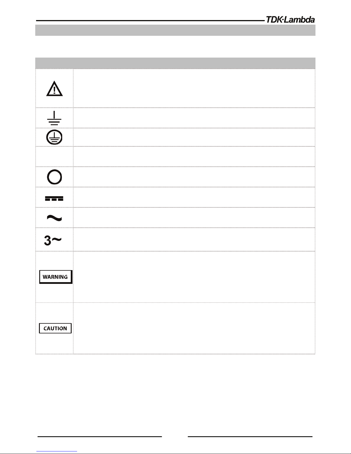
SYMBOLS/ ZEICHEN
Caution, risk of danger. Instruction manual symbol. The instrument will be marked with this symbol
when it is necessary for the user to refer to the Safety & Installation or Instruction manual.
Achtung Gefahr. Symbol im Benutzerhandbuch. Das Gerät wird mit diesem Symbol gekennzeichnet,
wenn der Benutzer auf das Sicherheits- & Installationshandbuch oder die Bedienungsanleitung
verwiesen wird.
Indicates ground terminal.
Zeigt einen Erdungsanschluss an.
Protective Ground Conductor Terminal.
Schutzleiterklemme.
ON (Supply).
EIN (Netzversorgung).
OFF (Supply).
AUS (Netzversorgung).
Direct current (DC).
Gleichstrom (DC).
Alternate current (AC).
Wechselstrom (AC).
Three-Phase Alternating Current (AC)
Drei-phasiger Wechselstrom (AC)
Denotes hazard. A procedure requires specific attention. Not following the procedure correctly
could result in a personal injury. A WARNING sign should not be skipped and all indicated
conditions must be fully understood and met.
Weist auf Gefahren hin, die eine besondere Aufmerksamkeit erfordern. Eine Nichteinhaltung
dieser Vorgehensweise, kann zu Körperverletzungen führen. Ein WARN-Hinweis sollte nicht
übergangen und alle angeführten Bedingungen müssen eindeutig verstanden und umgesetzt
werden.
Denotes hazard. A procedure requires specific attention. Not following the procedure correctly
could result in damage to the equipment. Do not proceed beyond a CAUTION sign until all indicated
conditions are fully understood and met.
Weist auf Gefahren hin, die eine besondere Aufmerksamkeit erfordern. Wenn die beschriebene
Vorgehensweise nicht korrekt durchgeführt wird, kann dadurch das Gerät beschädigt werden. Führen
Sie einem VORSICHTS-Hinweis erst durch, wenn Sie alle angezeigten Handlungen eindeutig verstanden
und umgesetzt haben.
I
Page 26

22
CHAPTER 1: GENERAL INFORMATION
1.1
User Manual Content
This safety & installation manual contains the operating instructions, installation instructions of the
™ 5000W power supply series. The instructions refer to the standard & Blank power
supplies, including the built-in USB, LAN and RS232/485 serial communication. For information related
to operation with the optional GPIB communication interface, refer to User manual (Chapter 8) in the
CD-ROM.
1.2
Introduction
1.2.1 General Description
™ Series power supplies are wide output range, high performance switching power supplies.
The ™ Series is power factor corrected and operates from worldwide AC voltage range
continuously. Output voltage and current are continuously displayed and indicators show the complete
operating status of the power supply (in the standard units). The Front Panel controls allow the user to
set the output parameters, the protection levels (Over-Voltage protection, Under-Voltage protection
and Foldback) and preview the settings (in the standard units). The rear panel includes the necessary
connectors to control and monitor the power supply operation by remote analog signals or by the builtin serial communication USB, RS232/485, and LAN.
IEEE is optional.
1.2.2 Multiple Output Power System
The ™ power supplies series can be configured into a programmable power system of up to
31 units using the built-in LAN, USB, or RS232/RS485 communication port in the power supply and
the RS485 linking cable provided with each power supply.
For further information regarding LAN interface, refer to the User manual (Chapter 5) in the CD-ROM.
For further information regarding optional IEEE interface, refer to the User manual (Chapter 8) in the
CD-ROM.
1.2.3 Control via LAN, USB or RS232/485 Communication Ports
The following basic functional parameters can be programmed via communication ports:
• Output voltage setting.
• Output current setting.
• Output voltage measurement.
• Output current measurement.
• Output on/off control.
• Foldback protection setting.
• Over-voltage protection setting and readback.
• Under-Voltage protection setting and readback.
Page 27

23
• Under-Voltage limit setting and read back.
• Power-supply start up mode (last setting or safe mode).
1.2.4 Analog Voltage Programming and Monitoring
Analog inputs and outputs are provided at the rear panel for analog control of the power supply. The
output voltage and the current limit can be programmed by analog voltage or by resistor,
and can
be monitored by analog voltage. The power supply output can be remotely set to On or Off and
analog signals monitor the proper operation of the power supply and the mode of
operation
(CV/CC).
1.2.5 Parallel Operation
Up to four
™ Series power supplies of the same output voltage and current rating can be
paralleled
in master-slave configuration with automatic current sharing to increase available power.
1.2.6 Output Connections
Output connections are made to rear panel Connector. Either the positive or negative terminal may
be grounded or the output may be floated. Models up to 100VDC rated output shall not float outputs
more than +/- 200VDC above/below chassis ground. Models up to 600VDC rated output shall not
float outputs more than +/- 600VDC above/below chassis ground. Contact factory for assistance with
higher float voltage applications. Local or remote sense may be used.
1.2.7 Cooling and Mechanical Construction
The ™ Series is cooled by an internal fan. At installation, care must be taken to allow free air
flow into the power supply via the front panel, and out of the power supply via the rear panel.
1.3
Accessories
1.3.1 Accessories provided with the power supply
1.3.1.1 Input connector protection, includes 3 parts:
•
Strain relief bracket assembly.
•
Strain relief P/N: 5301 5440 (LAPP GROUP).
•
Lock nut P/N: 8216 (AGRO).
1.3.1.2 AC Input Plug P/N: PC 5/ 4-STCL1-7, 62 (Phoenix contact)
1.3.1.3 Output connector/ Bus bars protection
•
Output protection assembly.
• Output Plug P/N: PC 5/ 4-STCL1-7, 62 (Phoenix contact), for output voltage including and above
150VDC.Serial Link Cable
1.3.1.4 Serial link cable
Serial link cable, for linking power supplies by RS485 communication.
Cable description: 0.5m length, shielded, RJ-45 type plugs, 8 contacts (P/N: GEN/RJ45).
Page 28

24
1.3.1.5 Misc. Hardware
•
DB-26 Connector P/N: 10090769-P264ALF
(FCI)
•
DB-15 Backshell P/N: 86303638BLF (FCI)
• CD-ROM
• SEMS Screw M3X6 Fe Ni, 2 Pcs.
• Flat head screw M3X8 Fe Ni, 2 Pcs.
1.3.1.6 Bus bars Screws kits
10V~40V Models
• Hex. Screw M10X25 St. St., Type DIN933, 4 Pcs.
• Hex. Nut M10 St. St., Type DIN493B, 4 Pcs.
• Flat washer M10 St. St., Type DIN125A, 8 Pcs.
• Spring washer M10 St. St., Type DIN127B, 4 Pcs.
60V~100V Models
• Hex. Screw M8X25 St. St., Type DIN933, 2 Pcs.
• Hex. Nut M8 St. St., Type DIN493B, 2 Pcs.
• Flat washer M8 St. St., Type DIN125A, 4 Pcs.
• Spring washer M8 St. St., Type DIN127A, 2 Pcs.
1.3.2 Optional accessories
1.3.2.1 Printed User Manuals
For ordering printed User manual, the P/N is: G/M
1.3.2.2 Serial Port Cables
• For ordering serial port cables refer to the User manual in the CD-ROM.
• USB/LAN cables are not provided with the power supply.
1.3.2.3 Paralleling Cable
• For ordering paralleling cables refer to the User manual in the CD-ROM.
1.3.2.4 AC Cables
AC Cables are not provided with the power supply. Refer to
Table 1-1
for recommended AC
input cables (customer applied).
AC Input Range
AC Input Cable
190~240~, Three phase Min. 4 X 12AWG (Three wires plus Safety ground), stranded copper,
300V, 60°C minimum, 3m max. length, outer diameter 10~14mm.
380~480~, Three phase Min. 4 X 16AWG (Three wires plus Safety ground), stranded copper,
600V, 60°C minimum, 3m max. length, outer diameter 10~14mm.
Table 1-1: Recommended AC Input Cables
Page 29

25
CHAPTER 2: FRONT/REAR PANEL CONTROLS AND CONNECTORS
2.1
Introduction
The
™ Power Supply series has a full set of controls, indicators
(in the standard units)
and connectors that allow the
user to set up and operate the unit. Before starting to operate the unit,
please read the following
sections for an explanation of the functions, controls and connector
terminals.
• Section 2.2: Front Panel Display and Controls.
• Section 2.3: Rear Panel Controls and Connectors.
2.2
Front Panel Display and Controls
Refer to Figure 2-1and Table 2-1 for description of the Front panel controls.
Figure 2-1: Front panel controls and indicators
No.
Control/Indicator
Description
Section
1 Power Switch POWER ON/OFF control
2 Power Supply Model Model, Voltage & Current Identifier
3 Voltage Encoder and
button
Encoder: High-resolution detent rotary Encoder for adjusting the
output voltage. Button: Auxiliary function to accept voltage-setting
value.
4 Voltage Display 4-digit 16-segment voltage display. Normally displays the output
voltage. In preview mode, the display indicates the program setting
of output voltage. In menu navigation, the display indicates the
selected function.
5 Operation mode indicator CV/CC/CP operation mode indicator.
6 Current Display 4-digit 16-segment current display. Normally displays the output
current. In preview mode, the display indicates the program setting
of output current. In menu navigation, the display indicates the
selected parameter.
7 Indicators bar
Refer to Fig 2.2 and Table 2.2 in the User manual for description of
the front panel indicators bar.
8 Current Encoder and
button
Encoder: High-resolution detent rotary Encoder for adjusting the
output current. Button: Auxiliary function to accept current-setting
value, select menu level & accept set parameter value.
9 BACK button Return one-step back in menu navigation mode.
10 PROG button / Indicator
Activates Program / Sequencer menu. Program menu provides
Sequencer function control, Trigger function control and load a
sequence stored inside Power Supply memory.
Green LED lights when Program menu is active. If Program menu is
active, PROG button press exits to main display.
9
1
3
6 7 8
2
4 5 10
11
12
13
14
15
16
17
9
Page 30

26
No.
Control/Indicator
Description
Section
11 SYST / Lock Front Panel
button / Indicator
Activates System menu. System menu provides output sensing
point selection (Local / Remote sense), Interlock function control,
Enable function control, Power Supply OK signal control,
SAVE/RECALL Power Supply configuration, Programmable Signals
control, Preload function control, Display brightness & dimming
function control & reset power Supply settings.
Green LED lights when System menu is active. If System menu is
active, SYST button press exits to main menu. Lock / Un-Lock front
panel buttons by pressing SYST button and accept by Current
Encoder button.
12 CONF button / Indicator
Activates Configuration menu. Configuration menu provides POWER
Supply start mode control, Voltage & Current source control,
Analog Programming / Monitoring range selection, Internal
Resistance function, Constant power limit function & Slew-Rate
control function. Green LED lights when Configuration menu is
active. If Configuration menu is active, CONF button press exits to
main menu.
13 PROT button / Indicator
Activates Protection menu. Protection menu provides OVP setting,
UVL setting, UVP function control, Foldback function control and
OCL function ON/OFF control. Green LED lights when Protection
menu is active. If Protection menu is active, PROT button press
exits to main menu.
14 COMM button / Indicator
Activates Communication menu. Communication menu provides
communication interface selection, Power Supply address selection,
LAN settings control, communication baud-rate selection,
communication language selection and software revision
information. Green LED lights when Communication menu is active.
If Communication menu is active, COMM button press exits to main
menu.
15 FINE button / Indicator
Voltage/Current Fine/Coarse adjustment control. Operates as a
toggle switch. In Fine mode, VOLTAGE and Current encoders
operate in high-resolution mode. In Coarse mode, Voltage and
Current encoders operate in standard-resolution (approx. 3 turns
for full voltage/current rated scale). Green LED, lights when the
unit is in Fine mode.
16 PREV button / indicator Press PREV to display output voltage and current limit settings. The
display will show the settings for 15 seconds, it will return back to
show actual output voltage and current if buttons are not pressed
for 15 seconds. Green LED, lights when PREV mode is active.
17 OUT button / indicator
Output ON/OFF control. Press OUTPUT to set the output ON or
OFF. Green LED, lights when DC Output is enabled.
Table 2-1: Front panel controls and indicators
Page 31
27
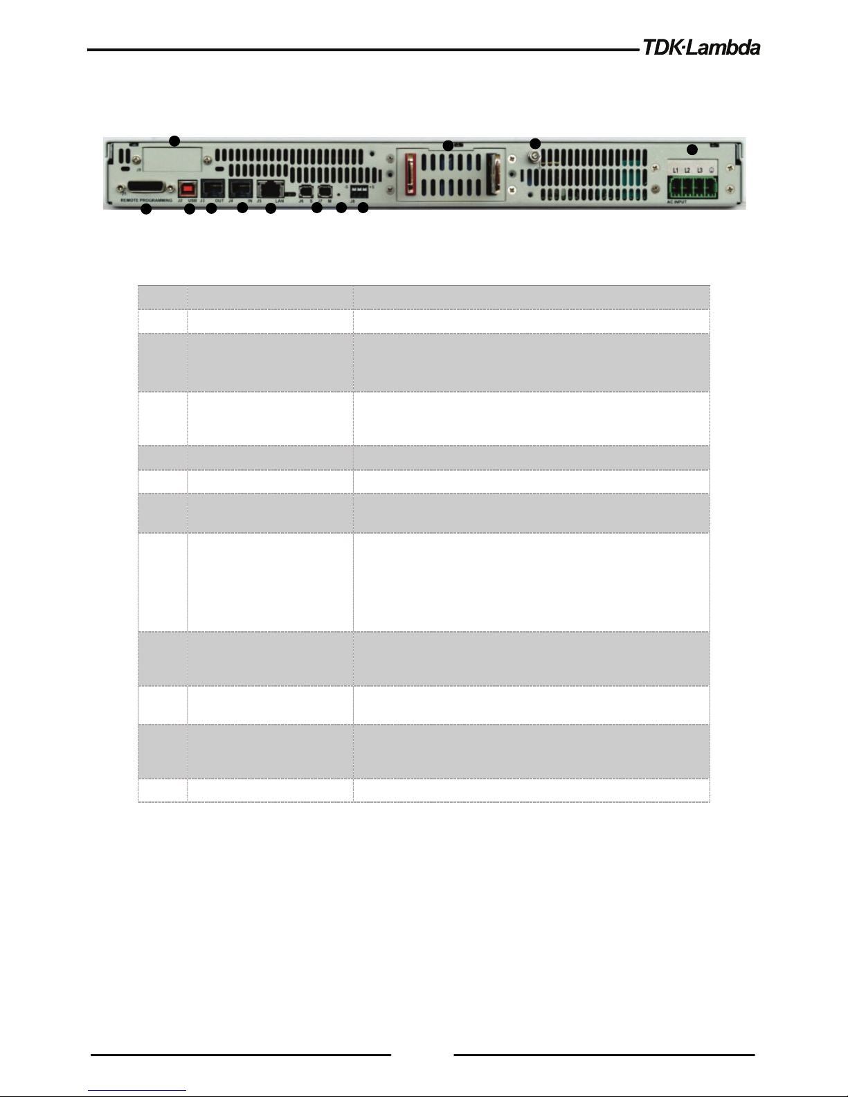
2.3
Rear Panel Connectors
Refer to Figure 2-2 and Table 2-2 for description of the Rear Panel connectors.
Figure 2-2: Rear panel connectors
No.
Connection
Description
1 AC Input Connector Connector type: Phoenix contact P/N: PC 5/ 4-G-7,62
2 Ground Stud Functional Ground connection M4x8 Stud
3
DC output bus-bar /
Connector
Bus-bars for 10V to 100V models.
Phoenix contact P/N: IPC 5/ 4-GF-7,62 for 150V to 600V
models.
4 Remote sense connector Connector for remote sensing connections. Connect to the
load for regulation of the load voltage and compensation of
load wire drop.
5 Reset button Set default Power Supply settings.
6 Paralleling Connectors Master/Slave connectors, mini I/O type.
7
LAN Connector +
Indicators
LAN interface connector, RJ-45 type + LXI indicators.
Connector type: UDE P/N: 26-31024KB91-1.
8 Serial In connector
RJ-45 type connector, used for connecting power supplies to
RS232 or RS485 port of a computer for remote control
purposes. When using several power supplies in a power
system, the first unit Remote-In is connected to the computer
and the remaining units are chained, Remote-In to RemoteOut. Connector type: Molex 95540-2881.
9 Serial Out connector RJ-45 type connector, used for chaining power supplies
to/from a serial communication bus. Connector type: Molex
95540-2881.
10 USB Connector
USB interface connector, type B. Connector type: SAMTEC
P/N: USBR-B-S-F-O-TH.
11 Isolated control and signals Isolated analog Control and monitoring signals, isolated from
the output potential. Connector type: WE P/N:
618026325223.
12 Optional Interface Position for optional communication interface.
Table 2-2: Front panel controls and indicators
2
3
4 5 6 7 8
11
10
9
1
12
Page 32

28
CAUTION
To prevent ground loops and to maintain the isolation of the power supply when programming from
J1, use an ungrounded programming source.
VORSICHT
Um Erdschleifen zu verhindern und die Isolierung auf dem Netzgerät aufrecht zu erhalten, wenn
Sie von J1 programmieren, müssen Sie eine ungeerdete Programmierquelle benutzen.
WARNING
There is a potential shock hazard at the output when using a power supply with an output greater
than 60VDC. Use wires with minimum insulation rating equivalent to the maximum output voltage of
the power supply.
WARNUNG
Bei Einsatz einer Stromversorgung mit einer Ausgangsspannung von über 60VDC besteht die
Gefahr eines elektrischen Schlags. Verwenden Sie nur Leitungen mit Isolationsklassen, die
mindestens für die maximale Ausgangsspannung der Stromversorgung geeignet sind.
Page 33

29
CHAPTER 3: INSTALLATION
CAUTION
Observe all torque guidelines within this manual. Over torque may damage unit or accessories.
Such damage is not covered under manufacturer’s warranty
.
VORSICHT
Beachten Sie alle Drehmoment-Richtlinien in diesem Handbuch. Wird ein zu großes
Drehmoment eingestellt bzw.verwendet, können dadurch das Gerät oder die Zubehörteile
beschädigt werden. Solche Schäden sind nicht von der Hersteller-Garantie abgedeckt.
3.1
General
This chapter contains instructions for initial inspection, preparation for use and repackaging for
shipment. Connection to PC, setting the communication port and linking ™ power supplies
are described in the User manual.
NOTE:
™ power supplies generate magnetic fields, which might affect the operation of
other instruments. If your equipment is susceptible to magnetic fields, do not position it
adjacent to the power supply.
NOTIZ:
Die ™ Netzgeräte können magnetische Felder erzeugen, die den Betrieb
anderer Geräte möglicherweise beeinträchtigen. Wenn Ihr Gerät empfindlich gegenüber
magnetischen Feldern ist, positionieren Sie diese nicht in der Nähe des Netzgeräts.
3.2
Preparation for Use
In order to be operational, the power supply must be connected to an appropriate AC source. The AC
source voltage should be within the power supply specification. Do not apply power before reading, the
safety instructions and Section 3.6.
Table 3-1 below, describes the basic setup procedure. Follow the instructions in Table 3-1 in the
sequence given to prepare the power supply for use.
Page 34

30
Step no.
Item
Description
Reference
1 Inspection Initial physical inspection of the power supply Section 3.3
2 Installation
Installing the power supply, Ensuring adequate
ventilation.
Section 3.4
Section 3.5
3 AC source AC source requirements
Connecting the power supply to the AC source.
Safety instructions
Section 3.6
4 Test Turn-on checkout procedure. Section 3.7
5 Load connection Wire size selection. Local /Remote sensing. Single or
multiple loads.
Section 3.8
6 Default setting The power supply setting at shipment. User Manual
Table 3-1: Basic Setup Procedure
3.3
Initial Inspection
Prior to shipment this power supply was inspected and found free of mechanical or electrical defects.
Upon unpacking of the power supply, inspect for any damage which may have occurred in transit. The
inspection should confirm that there is no exterior damage to the power supply such as broken knobs
or connectors and that the front panel and meter faces are not scratched or cracked. Keep all packing
material until the inspection has been completed. If damage is detected, file a claim with carrier
immediately and notify the TDK-Lambda sales or service facility nearest you.
3.4
Rack Mounting
The ™ power supply series is designed to fit in a standard 19” equipment rack.
3.4.1 Install the Power Supply in a Rack
1. Use the front panel rack-mount brackets to install the power supply in the rack.
2. Use a support bar to provide adequate support for the rear of the power supply. Do not obstruct
the air exhaust at the rear panel of the Unit.
Page 35

31
3.4.2 Rack Mount Slides (Optional)
Use rack mount slides: General Devices Catalog Number: C-300-S-116. Part/Drawing Number:
CC3001-00-0160 or equivalent to install the unit in a standard 19" equipment rack. Refer to Figure 3-1
for slides assembly instructions. Use three #10-32x0.38"(max.) screws at each side. To prevent
internal damage, use the specified screw length only.
#1032x0.38"(max.)
screws
Tightening torque:
25.4~31.7Lbf -i nch
Figure 3-1: Rack – Mount Slides Assembly
3.5
Location, Mounting and Cooling
This power supply is fan cooled. The air intake is at the front panel and the exhaust is at the rear
panel. Upon installation allow cooling air to reach the front panel ventilation inlets.
CAUTION
Allow minimum 10cm (4”) of unrestricted air space at the front and the rear of the unit. The
power supply should be used in an area where the ambient temperature does not exceed
+50°C.
VORSICHT
Halten Sie vor und hinter dem Gerät einen lichten Mindestabstand von 10 cm ein. Das
Netzgerät sollte nur in Arbeitsbereichen benutzt werden, in denen die
Umgebungstemperatur +50 °C nicht übersteigt.
Page 36

32
3.6
AC Input Power Connection
This Power supply shall be connected to the AC source via protective device
(Circuit breaker, fuses…etc.), rated for 30A.
WARNING
There is a potential electrical shock hazard when using a power supply without input
protection. Do not connect power supply to AC supply line without input protection properly
assembled.
WARNUNG
Es besteht die Gefahr eines Stromschlags, wenn ein Netzgerät ohne Berührungsschutz in
Betrieb genommen wird. Schließen Sie das Netzgerät nicht an Ihren Versorgungskreis an,
wenn der Berührungsschutz nicht ordnungsgemäß angebracht wurde.
CAUTION
Connection of this power supply to an AC source should be made by an electrician or other
qualified personnel.
VORSICHT
Nur Elektriker oder anderes Fachpersonal sollten dieses Netzgerät an die
Wechselstromquelle anschließen.
CAUTION
There is a potential shock hazard if the power supply chassis (with cover in place) is not
connected to an electrical safety ground via the safety ground terminal in the AC input
connector.
VORSICHT
Es besteht die Gefahr eines möglichen Stromschlages, wenn das Gehäuse des
Netzgeräts (auch mit aufgesetzter Abdeckung) nicht über den vorgesehenen
Schutzleiteranschluss an dem Wechselstrom-Eingangsanschluss mit der elektrischen
Schutzerde verbunden ist.
Page 37

33
WARNING
Some components inside the power supply are at AC voltage even when the On/Off
switch is in the”Off” position. To avoid electric shock hazard, disconnect the AC cord
and load, and wait two minutes before removing cover. Cover removal is allowed
only
by TDK-Lambda qualified service personnel.
WARNUNG
An einigen Komponenten im Innern des Netzgeräts liegt auch dann noch
Wechselspannung an, wenn der Netzschalter bereits auf AUS steht. Um die Gefahr eines
Stromschlags zu verhindern, trennen Sie das Netzkabel vom Versorgungsnetz und warten
dann zwei Minuten, bevor Sie die Schutzabdeckung abnehmen. Nur qualifizierte
Servicekräfte von TDK-Lambda dürfen die Gehäuse-Abdeckung abnehmen.
CAUTION
AC Input Wires No Conductor Pretreatment: All kinds of copper conductors can be
clamped without pretreatment (Solid, Flexible, with ferrule, with/without plastic sleeve). It is
forbidden to solder the conductors. The solder tin yields and fractures under high pressure.
The result is an increased contact resistance and an excessive temperature rise. In
addition, corrosion caused by pickling or fluxes has been observed on soldered conductor
ends. Notch fractures at the transition point from the rigid to the flexible conductor area are
also possible.
VORSICHT
Wechselstrom- Zuleitungen - Der Innenleiter muss nicht vorbereitet werden:
Alle Arten von Kupferleitungen können ohne Vorbehandlung fest geklemmt werden (feste,
flexible Leiter, mit Aderendhülse, mit/ohne Kunststoffhülse). Es ist verboten, die Leiter
vorab zu verlöten. Das Lötzinn gibt unter Druck nach und bricht. Dies führt zu einem
erhöhten Kontaktwiderstand und erzeugt dadurch einen übermäßigen Temperaturanstieg.
Zusätzlich wurde auf gelöteten Leiterenden Korrosion durch Einsatz von Beiz- oder
Flussmitteln beobachtet. Kerbenbrüche am Übergangspunkt vom starren zum flexiblen
Leiterbereich sind ebenfalls möglich.
Page 38

34
CAUTION
The power supply ON/OFF switch is not the main "disconnect device" and does not
completely disconnect all the circuits from the AC source. An appropriately rated
"disconnect device" such as circuit breaker, type B plug on power cord, etc., shall be
provided in the final installation. The "disconnect device" shall disconnect all supply lines
simultaneously. The "disconnect device" must be easily accessible.
VORSICHT
Der eingebaute EIN- / AUS-Schalter des Netzgeräts ist nicht die Haupt-„Trennvorrichtung“
und trennt somit nicht alle Schaltkreise vollständig von der Wechselstromquelle. Eine
entsprechend bemessene „Trennvorrichtung“ wie ein Sicherungsautomat der Typ B Klasse
in der Netzversorgung usw. sollen in der endgültigen System-Installation vorhanden sein.
Diese „Trennvorrichtung“ sollte alle Versorgungsleitungen gleichzeitig unterbrechen und
muss für das Service-Personal einfach zugänglich sein.
3.6.1 AC Input Connector
1. Ensure that the AC cable is disconnected from any electrical potential before making any
connection to the power supply.
The AC input connector is a header (Phoenix Contact P/N: PC 5/ 4-G-7, 62), located in the rear
panel. The mating plug has screws connections (Phoenix Contact P/N: PC 5/ 4-STCL1-7, 62),
and is provided in the accessories kit.
2. Use suitable wires and tightening torque to connect the mating plug:
• Wire diameter: 12AWG (2.5mm²) for three-phase 200Vac models and
• 16AWG for three-phase 400Vac, 480Vac models.
• Tightening torque: 4.5-5.3 Lbf-inch. (0.5-0.6Nm).
AC Input Cord
WARNING
AC input cord is not provided with the power supply.
Refer to section 1.3.2.4 for details for the recommended AC input cables and to section 3.6 for
disconnect device requirement.
WARNUNG
Die Netzzuleitung ist nicht im Lieferumfang bei der Auslieferung des Netzgerätes.
Page 39

35
3.6.2 AC Input Wire Connection
1. Strip the outside insulation of the AC cable approx. 10cm. Trim the wires so that the ground wire
is 10mm longer than the other wires. Strip 10mm at the end of each of the wires.
2. Insert the Cable gland into the Strain relief bracket Assembly as shown in Figure 3-2.
3. Tighten the plastic nut (supplied in the accessories box), from the inside part of the bracket by
using manual force only.
Cable gland
Strain relief
brack et
Nut
Figure 3-2: Insertion of the Plastic Nut into Strain Relief Bracket
4. Unscrew the conical cable entry part, until it will not apply any stress to the AC cable.
5. Insert the AC cable through the conic cable gland entry and the strain relief bracket as shown in
Figure 3-3.
AC Cable
Conical cable
gland entry
AC wires to
connect
Figure 3-3: Stripped Wires Inserted Through
6. Insert the AC wires into the AC input connector (as shown in Figure 3-4).
Page 40

36
7. Tighten the screws, tightening torque: 4.5-5.3 Lbf-inch. (0.5-0.6Nm).
Figure 3-4: AC Wires Fixed to the AC Connector
8. After fixing the wires, close by manual force the cable gland conic entry part until the AC cable will
be well tightened. Beware not to apply excessive force.
Now the cable is securely fastened inside the strain relief assembly.
9. To fix the strain relief release assembly, unscrew 2 of the rear panel screws as shown in Figure
3-5. Do not reuse these screws.
Figure 3-5: Unscrew the Rear Panel Screws
10. Fix the strain relief assembly, by 2 M3x8 Flat head screws, supplied in the accessories box, as
shown in Figure 3-6. Tightening torque: 4.7-5.7 Lbf-inch. (0.53-0.64Nm).
Page 41

37
Figure 3-6: Strain Relief Assembled to the Power Supply Rear Panel
Page 42

38
3.7
Turn-On Checkout Procedure
WARNING
There is a potential electrical shock hazard when using a power supply without output
protection. Do not turn ON power without output protection properly assembled. Turn OFF
power supply or disconnect power supply from AC mains before making or changing any
rear panel connection.
WARNUNG
Wenn ein Netzgerät ohne Berührungssschutz benutzt wird, besteht die Gefahr eines
Stromschlags. Schalten Sie das Gerät nicht EIN, wenn der Berührungssschutz nicht
ordnungsgemäß angebracht ist. Schalten Sie das Netzgerät AUS oder trennen das
Netzgerät vom Versorgungsnetz ab, bevor Sie irgendwelche Anschlüsse an der
Geräterückseite vornehmen oder ändern.
3.7.1 General
The following procedure ensures that the power supply is operational and may be used as a basic
incoming inspection check. Refer to Figure 2-1 and Figure 2-2 for the location of the controls indicated
in the procedure. Please note that this procedure is valid for standard units. For blank units, all the
parameters settings and status reading can be made by using communication interfaces. Refer to the
User manual for further information.
3.7.2 Prior to Operation
1. Ensure that the power supply is configured to the default setting:
2. Power On/Off switch at Off position.
3. Ensure that the protection of output terminals is mounted and properly assembled.
4. Connect the unit to an AC source as described in section 3.6.
5. Connect a DVM with appropriate cables for the rated voltage to the output terminals.
6. Turn the front panel Power switch to On.
7. When power supply is turned ON and all LCD Display segments and LEDs illuminate
momentarily, then the LCD display shows: ”OUTP OFF”.
8. The power supply operating status is then displayed.
3.7.3 Constant Voltage Check
1. Turn on the output by pressing OUT button so the OUT LED illuminates.
2. Observe the power supply Voltage display and rotate the Voltage encoder.
3. Ensure that the output voltage varies while the Voltage encoder is rotated. The minimum control
range is from zero to the maximum rated output for the power supply model.
Page 43

39
4. Compare the DVM reading with the front panel Voltage display to verify the accuracy of the
Voltage display.
5. Ensure that the front panel CV indication on the LCD screen is active.
6. Turn off the front panel Power switch.
3.7.4 Constant Current Check
1. Ensure that the front panel Power switch is at Off position and the DVM connected to the output
terminals shows zero voltage.
2. Connect a DC shunt across the output terminals.
3. Ensure that the shunt and the wires current ratings are higher than the power supply rating.
4. Connect a DVM to the shunt.
5. Turn the front panel Power switch to On position.
6. Turn on the output by pressing the OUT button so the OUT LED illuminates.
7. Observe the power supply Current display and rotate the Current encoder.
8. Ensure that the output current varies while the Current encoder is rotated. The minimum control
range is from zero to the maximum rated output for the power supply model.
9. Compare the DVM reading with the front panel Current display to verify the accuracy of the
Current display.
10. Ensure that the front panel CC indication on the LCD screen is active.
11. Turn off the front panel Power switch.
12. Remove the shunt from the power supply output terminals.
3.8
Connecting the Load
1. Turn off the AC input power before making or changing any rear panel connection.
2. Ensure that all connections are securely tightened before applying power.
WARNING
There is a potential shock hazard when using a power supply with an output voltage
greater than 60VDC. Turn off the AC input power before making or changing any rear
panel connection.
Ensure that the protection of output plug is mounted and properly assembled for power
supplies when output voltage exceed 60VDC. Ensure that all connections are securely
tightened before applying power.
Page 44

40
WARNUNG
Bei Einsatz eines Netzgeräts mit einer Ausgangsspannung von über 60 VDC besteht das
Risiko eines Stromschlags. Schalten Sie die AC-Eingangsspannung immer AUS, bevor
Sie irgendwelche Anschlüsse an der Geräterückseite vornehmen oder verändern. Stellen
Sie sicher, dass die Schutzabdeckung des Ausgangssteckers ordnungsgemäß angebracht
ist, wenn Ausgangsspannungen von mehr als 60 VDC auftreten können. Stellen Sie sicher
dass alle Verbindungen sicher und fest angeschlossen sind, bevor Sie Spannung anlegen.
3.8.1 Load Wiring
The following considerations should be made to select wiring for connecting the load to the power
supply:
• Current carrying capacity of the wire (refer to section 3.8.2)
• Insulation rating of the wire should be at least equivalent to the maximum output voltage of the
power supply.
• Maximum wire length and voltage drop (refer to section 3.8.2)
• Noise and impedance effects of the load wiring (refer to3.8.4).
3.8.2 Current Carrying Capacity
Two factors must be considered when selecting the wire size:
• Wires should be at least heavy enough not to overheat while carrying the power supply load
current at the rated load, or the current that would flow in the event the load wires were shorted,
whichever is greater.
• Wire size should be selected to enable voltage drop per lead to be less than 1.0V at the rated
current. Although units will compensate higher voltage drop in each load wire (refer to the
specifications). It is recommended to minimize the voltage drop (1V maximum) to prevent
excessive output power consumption from the power supply and poor dynamic response to load
changes. Please refer to Table 3-2 for the recommended wires types to limit voltage drop in
American and European dimensions respectively.
Output current Recommended wires
(mm²)
Recommended
wires (AWG)
Recommended lugs/Connector
8.5A 1 16 AWG
Phoenix contact IPC 5/ 4-STF-7,62
(Supplied in Accessories kit)
17A 2.5 12 AWG
Phoenix contact IPC 5/ 4-STF-7,62
(Supplied in Accessories kit)
34A 6
Solid/Flexible/With ferrule
without plastic sleeve
10 AWG Phoenix contact IPC 5/ 4-STF-7,62
(Supplied in Accessories kit)
50A 10 6 AWG
6 AWG
Panduit LCMA10-8-C
Or equivalent
65A 16 4 AWG
4 AWG
Panduit LCMA16-8-C
Or equivalent
Page 45

41
Output current Recommended wires
(mm²)
Recommended
wires (AWG)
Recommended lugs/Connector
85A 25 2 AWG 2 AWG
Panduit LCMA25-8-C
Or equivalent
125A 50 "0" AWG
"0" AWG
Panduit LCMD50-10CD-X
Or equivalent
170A 70 3/0 = 000
3/0 = 000
Panduit LCMD70-10CD-X
Or equivalent
250A 95 4/0 = 0000 4/0 = 0000
Panduit LCMD95-10CD-X
Or equivalent
500A 95 X 2 In Parallel 4/0 = 0000
(2 In Parallel)
4/0 = 0000 (2 In Parallel)
Panduit LCMD95-10CD-X
Or equivalent
Table 3-2: Recommended Cable Size for Output Connection
3.8.3 Wire Termination
The wires should be properly terminated with terminals securely attached. DO NOT use nonterminated wires for load connection at the power supply.
CAUTION
Reversing the sense wires might cause damage to the power supply in local and remote
sensing. (Do not connect -S to +V or +S to -V.)
VORSICHT
Ein verpolter Anschluss der Fühlerleitungen an die Last, kann zu einem Defekt der
Stromversorgung sowohl bei lokalem als auch bei entferntem Sensebetrieb führen.
(Niemals die Anschlüsse des –S auf +V bzw. +S auf –V verschalten.)
3.8.4 Noise and Impedance Effects
To minimize the noise pickup or radiation, the load wires and remote sense wires should be twisted pairs
to the shortest possible length. Shielding of sense leads may be necessary in high noise
environments. Where shielding is used, connect the shield to the chassis via a rear panel Ground
screw. Even if noise is not a concern, the load and remote sense wires should be twisted-pairs to
reduce coupling, which might impact the stability of power supply. The sense leads should be
separated from the power leads.
Page 46

42
3.8.5 Inductive Loads
Inductive loads can produce voltage spikes that may be harmful to the power supply. A diode
should be connected across the output. The diode voltage and current rating should be greater
than the power supply maximum output voltage and current rating. Connect the cathode to the
positive output and the anode to the negative output of the power supply.
Where positive load transients such as back EMF from a motor may occur, connect a surge
suppressor across the output to protect the power supply. The breakdown voltage rating of the
suppressor must be approximately 10% higher than the maximum output voltage of the power supply.
3.8.6 Making the Load Connections
WARNING
Hazardous voltages may exist at the outputs and the load connections when using a power
supply with a rated output greater than 40V. To protect personnel against accidental
contact with the hazardous voltages, ensure that the load and its connections have no
accessible live parts. Ensure that the load wiring insulation rating is greater than, or equal
to, the maximum output voltage of the power supply. Ensure that the protection of output
Connector/ Bus bars is properly assembled.
WARNUNG
An den Ausgängen und den Ladungsanschlüssen kann gefährliche Spannung anliegen,
wenn ein Netzgerät mit einer Nennleistung von mehr als 40V benutzt wird. Vergewissern
Sie sich, dass es an der Last und ihren Anschlüssen keine berührbaren
spannungsführenden Teile gibt, um das Personal vor unbeabsichtigtem Kontakt mit
gefährlicher Spannung zu schützen. Vergewissern Sie sich, dass die Nennisolierung des
stromführenden Leiters höher als die maximale Ausgangsspannung des Netzteils ist oder
ihr entspricht. Vergewissern Sie sich, dass der Schutz des Ausgangsleiters /
Stromanschlusses ordnungsgemäß installiert ist.
CAUTION
Ensure that the load wiring mounting hardware does not short the output terminals. Heavy
connecting cables must have some form of strain relief to prevent loosening the connections
or bending the bus bars.
VORSICHT
Vergewissern Sie sich, dass die Befestigungsmaterialien der Lastverdrahtung die
Ausgangsklemmen nicht kurzschließt. Schwere Verbindungskabel müssen über eine Art
von Zugentlastung verfügen, um ein Lösen der Verbindungen oder Verbiegen der
Stromanschlüsse zu verhindern.
For All models:
Page 47

43
1. Prepare suitable wires and lugs according to the recommendations in Table 3-2.
2. Assemble and solder the lugs properly.
10V ~ 40V Models
CAUTION
For high current outputs, it is very important to make the output connections properly, and follow
the instructions. Improper connections may result in the
excessive temperature rise
or power
supply going into protection mode (When the voltage drop on load wires is higher than specified
in the specifications).
VORSICHT
Es ist sehr wichtig, bei hohen Stromabgaben die Ausgangsanschlüsse ordnungsgemäß
herzustellen und die Anweisungen zu befolgen. Unsachgemäße Anschlüsse können zu
einem übermäßigen Temperaturanstieg führen oder der Grund dafür sein, dass das
Netzgerät in den Schutzmodus schaltet (wenn der Spannungsabfall auf den
stromführenden Leitern die Spezifikationen überschreitet).
1. Open the output protection assembly, (supplied in the accessories kit) by unscrewing the screw in
the rear side as shown in Figure 3-7. Remove both plastic protectors.
Plastic
protector
Sc re w
Plastic
protector
Figure 3-7: Disassembly of Output Protection
Page 48

44
For 10V model only:
1. Fix the wires to the Bus bars as shown in Figure 3-8.
2. Close the output protection assembly. In this model the plastic protectors will not be assembled.
M10
Screws
M10 Hex. Nu t
Tightening torque:
220 ~ 265 lbf-in.
24.9~ 29.9 Nm
Flat
Washers
Flat w asher
close to Bus
bar s, then,
spring washer
Figure 3-8: Assembly of 10V Wires
For 20V ~ 40V models:
1. Remove & Separate each plastic protector to two parts by cutting the plastic bridge between both
parts, as shown in Figure 3-9.
2. Insert back to the protection assembly only the specified part, as shown in Figure 3-9.
Cut line
Insert this part to
the protection
assembly
Figure 3-9: Plastic Protectors Separation
3. Fix the wires to the bus bars as shown in Figure 3-10. Close the output protection assembly with
one part of the plastic protector assembled on each side, as shown in Figure 3-10.
Page 49

45
M10
Screws
Flat w asher close
to Bus bars, then
spring washer
Flat
Washers
M10 Hex. Nut
Tightening torque:
220 ~ 265 lbf-in.
24.9~ 29.9 Nm
One part of
plastic
protector
assembled
Figure 3-10: 20V ~ 40V Wires Assembly
4. Assemble the Bus bars protection assembly to the rear panel of the power supply, by using 2
M3X6 Sems screws from the accessories kit, as shown in Figure 3-11.
Tightening torque: 4.7 ~ 5.7
Lbf-inch (0.53 ~ 0.64 Nm).
Figure 3-11: Fixing Bus bars protection assembly to the rear panel
Page 50
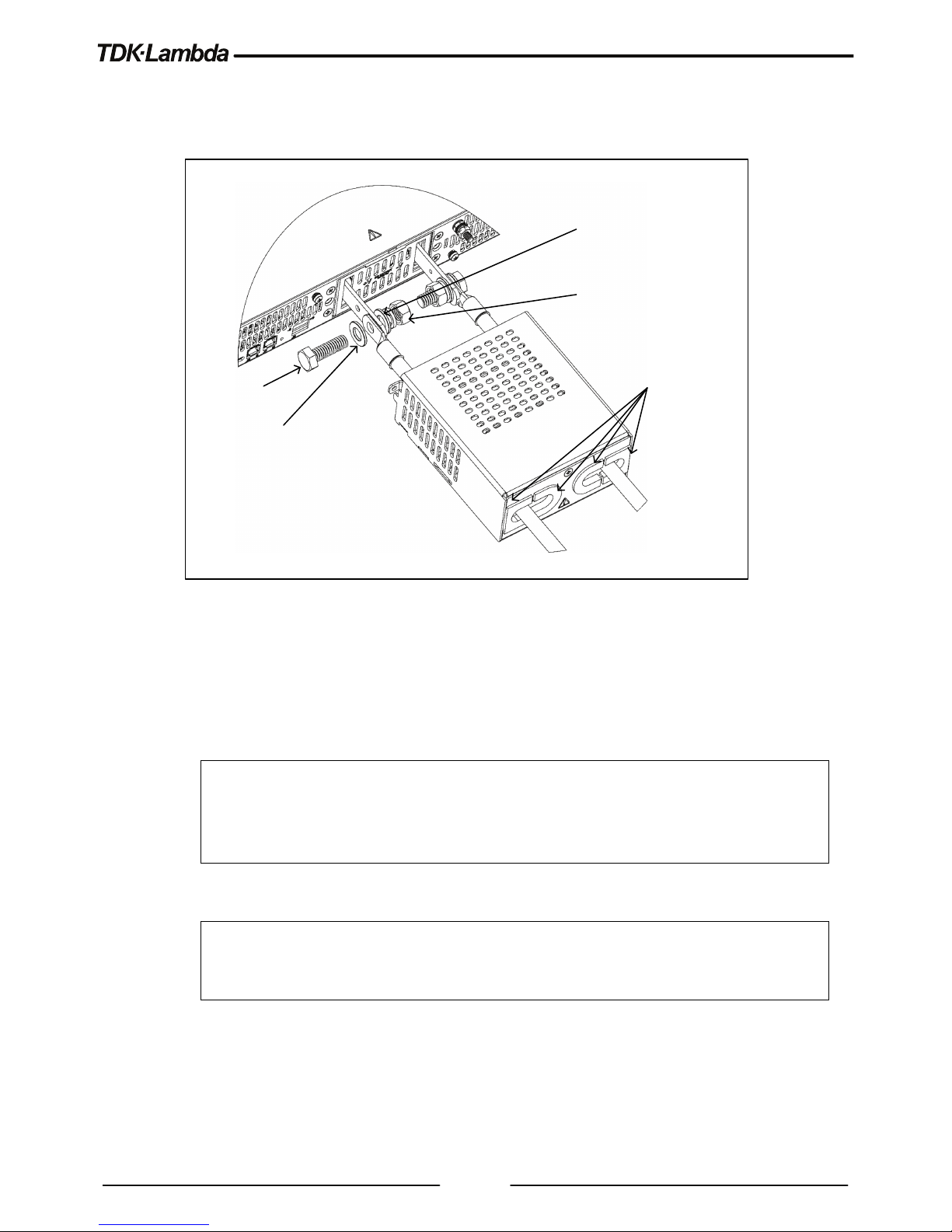
46
For 60V ~ 100V models:
1. The recommended wires according to Table 3-2 can be inserted through the output protection
assembly. No need to open the output protection assembly. Refer to Figure 3-12:
Flat w ash er close
to Bus bars, then
spring wa sher
M8 Hex. Nut
Tightening torque:
106 ~ 132 lbf-in.
12~ 14.9 Nm
Flat w ash ers
M8 Screws
Both parts of
plastic protecto r
assembled
Figure 3-12: 60V ~ 100V Wires assembly
2. Assemble the bus bars protection as shown in Figure 3-11 (the same way as for 10V~40V).
For 150V to 600V models:
WARNING
There is a potential shock hazard when using a power supply with an output voltage
greater than 60VDC. Do not turn ON power supply when output voltage is above 60VDC
without output plug protection assembled. Ensure that the protection of output plug is
mounted and properly assembled.
WARNUNG
Bei Einsatz eines Netzgeräts mit mehr als 60VDC Nennspannung besteht das Risiko
eines Stromschlags.
Schalten Sie kein Netzgerät mit einer
Ausgangsspannung von mehr
als 60VDC EIN, wenn die Schutzabdeckung des Ausgangssteckers nicht installiert ist
.
Page 51

47
CAUTION
Output Wires No Conductor Pretreatment: All kinds of copper conductors can be
clamped without pretreatment (Solid, Flexible, with ferrule, with/without plastic sleeve). It is
forbidden to solder the conductors. The solder tin yields and fractures under high pressure.
The result is an increased contact resistance and an excessive temperature rise. In
addition, corrosion caused by pickling or fluxes has been observed on soldered conductor
ends. Notch fractures at the transition point from the rigid to the flexible conductor area are
also possible.
VORSICHT
Ausgangsleitungen Keine Leitervorbehandlung: Alle Arten von Kupferleitungen können
ohne Vorbehandlung fest geklemmt werden (feste, flexible, mit Aderendhülse, mit/ohne
Kunststoffhülse). Es ist verboten, die Leiter zu löten. Das Lötzinn gibt unter Druck nach und
bricht. Dies führt zu einem erhöhten Kontaktwiderstand und einem übermäßigen
Temperaturanstieg. Zusätzlich wurde auf gelöteten Leiterenden von Beiz- oder
Flussmitteln verursachter Rost beobachtet. Kerbenbrüche am Übergangspunkt vom
starren zum flexiblen Leiterbereich sind ebenfalls möglich.
The 150V to 600V models have four terminal wire clamp output connector. The two left terminals are
positive outputs and the other two right terminals are the negative outputs.
The connector requirements are as follows:
• Connector type: IPC 5/ 4-STF-7, 62 (Phoenix contact, supplied in the accessories kit).
• Wires: AWG10 to AWG16, according to table 3-2.
Follow the below instructions for connection of the load wires to the power supply:
1. Refer to Table 3-2 for the recommended load wires. Strip approx. 10mm at the end of each of the
wires.
2. Loosen the mating connector terminal screws.
3. Insert the wires through the output protection assembly as shown in Figure 3-13.
4. Insert the stripped wires into the terminal and tighten the terminal screw securely (see Figure
3-13).
Tightening torque: 6.2-7 Lbf-inch. (0.7-0.8Nm).
Page 52

48
Mating CONNECTOR
(IPC 5/ 4-STF-7,62,
PHOENIX CONTACT)
Figure 3-13: Load Wires Connection to the Output Plug
5. Fix the Output protection assembly to the rear panel of the power supply and tighten the screws
as shown in Figure 3-14. Tightening torque: 4.7 ~ 5.7 Lb-inch (0.53 ~ 0.64 Nm).
Figure 3-14: Output Connector Protection Assembly
Page 53

49
3.8.7 Grounding Outputs
Either the positive or negative output terminals can be grounded. To avoid noise problems caused by
common-mode current flowing from the load to ground, it is recommended to ground the
output
terminal as close as possible to the power supply chassis ground.
Always use two wires to connect the load to the power supply regardless of how the system is
grounded.
NOTE
When grounding output terminals as a part of series connection, several precautions must
be taken into consideration. Refer to the User manual, section 3.4.
WARNING
There is a potential shock hazard at the RS232/485, LAN, USB and the IEEE ports when
using power supplies in series with combined voltage greater than 600V, and the Positive
Output of the Power Supply is grounded. Do Not connect the Positive Output to ground
when using the RS232/485, LAN or IEEE.
WARNUNG
Wenn in Reihe geschaltete Netzgeräte mit einer kombinierten Spannung von mehr als
600V benutzt werden und der positive Ausgang des Netzgeräts geerdet ist, besteht das
Risiko eines Stromschlags an den RS232/485, LAN-, USB- und IEEE-Ports. Schließen
Sie den positiven Ausgang nicht an die Masse an, wenn Sie RS232/485, LAN oder
IEEE benutzen.
Page 54

50
3.9
Local and Remote Sensing
The rear panel J8 sense connector may be used to configure the power supply for remote sensing of
the output voltage. Refer to Figure 2-2 for sense connector location.
3.9.1 Sense Wiring
WARNING
There is a potential shock hazard at the sense connector when using a power supply with
an output voltage greater than 60VDC. Remote sense wires should have a minimum
insulation rating equivalent or greater than the maximum output voltage of the power
supply. Ensure that the connections at the load end are shielded to prevent accidental
contact with the hazardous voltages.
WARNUNG
Bei Netzgeräten mit einer Ausgangsspannung von mehr als 60VDC besteht an der Sense-Buchse
die Gefahr eines elektrischen Schlags. Fühler-Leitungen sollten eine minimale Nennisolierung
besitzen, die größer als die maximale Ausgangsspannung des Netzgeräts ist oder ihr entspricht.
Vergewissern Sie sich, dass die Anschlüsse am Ladungsende geschützt sind, um
versehentlichen Kontakt mit gefährlichen Spannungen zu verhindern
.
3.9.2 Local Sensing
The power supply is shipped with unconnected J8 sense connector. In this configuration, the unit is
sensing the output voltage at the output terminals. Refer to Table 3-3 for J8 terminals assignment. This
method does not compensate for voltage drop on the load wires, therefore it is recommended only for
low load current applications or where the load regulation is less critical.
3.9.3 Remote Sensing
WARNING
There is a potential shock hazard at the sense point when using power supply with an
output voltage greater than 60VDC. Ensure that the connections at the load end are
shielded to prevent accidental contact with the hazardous voltages.
WARNUNG
Bei Einsatz eines Netzgeräts mit einer Ausgangsspannung von mehr als 60VDC besteht am SensePunkt das Risiko eines elektrischen Schlags. Vergewissern Sie sich, dass die Anschlüsse am LastEnde geschützt sind, um versehentlichen Kontakt mit gefährlicher Spannung zu vermeiden
.
CAUTION
When using shielded sense wires, ground the shield in one place only. The location can be
the power supply chassis or one of the output terminals.
Page 55

51
VORSICHT
Wenn Sie abgeschirmte Sense-Leitungen verwenden, erden Sie die Abschirmung nur an
einer Seite. Dies kann entweder am Gehäuse des Netzteils oder an eine der
Ausgangsanschlüsse erfolgen.
Terminal
Function
J8 - Negative Remote negative sense (-S).
J8 - Positive Remote positive sense (+S).
Table 3-3: J8 Terminals
Use remote sense where the load regulation at the load end is critical. In remote sense, the power
supply will compensate for voltage drop on the load wires.
Refer to the specifications for the maximum allowable voltage drop on load wires.
The voltage drop is subtracted from the total voltage available at the output. Follow the instructions
below to configure the power supply for remote sensing:
1. Ensure that the Power supply AC connection is Off.
2. Connect the negative sense lead to terminal J8 (-S) and the positive sense lead to terminal J8
(+S).
3. Turn On the power supply.
NOTE
In order to ensure correct operation in remote sense mode, ensure that the voltage drop on the
sensing wires is meeting the product specifications.
3.9.4 J8 Sense Connector Technical Information
• J8 connector type: SPT-THR 1, 5/ 3-H-3, 5 P26, Phoenix contact.
• Wire AWG: 24 up to 18.
• Wire type: Solid, Flexible conductor or conductor with ferrule without plastic sleeve: up to 1.5mm².
• Conductor with ferrule with plastic sleeve: up to 0.75mm².
In order to connect the wires to the sense connector, strip up to 8mm of wire insulation. Insert the wire
into the terminal, while pressing on the white pusher. After full insertion, release the white pusher for
wire locking inside the terminal.
3.9.5 Repackaging for Shipment
To ensure safe transportation of the instrument, contact the TDK-Lambda sales or service facility near
you for Return Authorization and shipping information.
Please attach a tag to the power supply describing the problem and specifying the owner, model
number and serial number of the power supply.
Refer to Warranty Information for further instructions.
Page 56

NOTES
________________________________________________
________________________________________________
________________________________________________
________________________________________________
________________________________________________
________________________________________________
________________________________________________
________________________________________________
________________________________________________
________________________________________________
________________________________________________
________________________________________________
________________________________________________
________________________________________________
________________________________________________
________________________________________________
________________________________________________
________________________________________________
________________________________________________
________________________________________________
________________________________________________
________________________________________________
________________________________________________
________________________________________________
________________________________________________
________________________________________________
________________________________________________
 Loading...