

Page 1
Page 1 of 23 17814 issue 16, October 2018
NVM175 Handbook
ENGLISH
General Safety Instructions:
READ SAFETY INSTRUCTIONS
Servicing:
These products are not customer serviceable. TDK-Lambda UK LTD. and their authorised agents only are
permitted to carry out repairs.
Critical Components:
These products are not authorised for use as critical components in nuclear control systems, life support
systems or equipment for use in hazardous environments without the express written approval of the
Managing Director of TDK-Lambda EMEA.
Product Usage:
These products are designed for use within a host equipment which restricts access to authorised competent
personnel.
This product is a component power supply and is only to be installed by qualified persons within other
equipment and must not be operated as a stand alone product.
This product is for sale to business to business customers and can be obtained via distribution channels.
It is not intended for sale to end users.
This product is a component power supply and does not fall within the scope of the EMC directive.
Compliance with the EMC directive must be considered in the final installation. Please contact your local
TDK-Lambda office.
Environmental:
These products are IPX0, and therefore chemicals/solvents, cleaning agents and other liquids must not be
used.
Environment:
This power supply is a switch mode power supply for use in applications within a Pollution Degree 2,
overvoltage category II environment. Material Group IIIb PCB’s are used within it.
Output Loading:
The output power taken from the power supply must not exceed the rating stated on the power supply label,
except as stated in the product limitations in this handbook.
Input Parameters:
This product must be operated within the input parameters stated in the product limitations in this handbook.
End of Life Disposal:
The unit contains components that require special disposal. Make sure that the unit is properly disposed of at
the end of its service life and in accordance with local regulations.
RISK OF ELECTRIC SHOCK
High Voltage Warning:
Dangerous voltages are present within the power supply. The professional installer must protect service
personnel from inadvertent contact with these dangerous voltages in the end equipment.
WARNING: When installed in a Class 1 end equipment, this product must be reliably earthed and
professionally installed.
When installed in a Class II end equipment, no earthing connection to the power supply is required.
Page 2
Page 2 of 23 17814 issue 16, October 2018
NVM175 Handbook
CAUTION: DOUBLE POLE/NEUTRAL FUSING
The (+) or (-) output(s) can be earthed or left floating.
The unit cover(s)/chassis must not be made user accessible.
The mains input connector is not acceptable for use as field wiring terminals.
For encased products, do not use mounting screws, which penetrate the unit more than 4.5mm.
Internal fuses protect the unit and must not be replaced by the user. In case of internal defect, the unit must
be returned to TDK-Lambda UK LTD or one of their authorised agents.
WARNING: These products are Class 1 and must therefore be reliably earthed and professionally installed in
accordance with the prevailing electrical wiring regulations and the safety standards covered herein.
A suitable mechanical, electrical and fire enclosure must be provided by the end use equipment for
mechanical, electric shock and fire hazard protection.
The ventilation openings on these products must not be impeded. Ensure that there is at least 50mm spacing
between any obstruction and the ventilation openings.
The unit cover/chassis is designed to protect skilled personnel from hazards. They must not be used as part
of the external covers of any equipment where they may be accessible to operators, since under full load
conditions, part or parts of the unit chassis may reach temperatures in excess of those considered safe for
operator access.
Page 3
Page 3 of 23 17814 issue 16, October 2018
NVM175 Handbook
DEUTSCH
Allgemeine Sicherheitsvorschriften:
LESEN SIE DIE SICHERHEITSVORSCHRIFTEN
Wartung:
Diese Produkte können nicht durch den Kunden gewartet werden. Nur TDK-Lambda UK LTD. und deren
zugelassene Vertriebshändler sind zur Durchführung von Reparaturen berechtigt.
Kritische Komponenten:
Diese Produkte sind nicht für die Verwendung als kritische Komponenten in nuklearen Kontrollsystemen,
Lebenserhaltungssystemen oder Geräten in gefährlichen Umgebungen geeignet, sofern dies nicht
ausdrücklich und in Schriftform durch den Geschäftsführer von TDK-Lambda EMEA genehmigt wurde.
Produktverwendung:
Diese Produkte sind zur Verwendung innerhalb von Host-Anlagen gedacht, die einen auf das Fachpersonal
beschränkten Zugang haben.
Dieses Produkt ist eine Stromversorgungs-Komponente und sie darf nur von qualifiziertem Personal in
andere Geräte eingebaut werden und sie darf NICHT als eigenständiges ("Stand-Alone") Gerät betrieben
werden.
Dieses Produkt ist für den Verkauf an Geschäftskunden entwickelt worden und es kann über
Distributionskanäle bezogen werden.
Es ist NICHT für den Verkauf an Endkunden gedacht und konzipiert.
Dieses Produkt ist eine Stromversorgungsbaugruppe und sie fällt NICHT in den Bereich der EMV Direktive.
Die Konformität mit der EMV Richtlinie muss in der finalen Gesamtinstallation betrachtet werden.
Bitte kontaktieren Sie Ihr regionales TDK-Lambda Vertriebsbüro im Falle von Rückfragen.
Umwelt:
Diese Produkte sind IPX0, aus diesem Grund dürfen keine Chemikalien/Lösungsmittel, Reinigungsmittel und
andere Flüssigkeiten verwendet werden.
Umgebung:
Dieses Netzteil ist ein Schaltnetzteil zur Verwendung in einer Umgebung mit einem Verschmutzungsgrad 2,
Überspannungskategorie II. Materialgruppe IIIb mit darin verwendeten PCBs.
Ausgangsstrom:
Der Ausgangsstrom des Netzteiles darf die Leistung, die auf dem Label des Netzteiles vermerkt ist, nur dann
überschreiten, wenn dies in den Produktgrenzen dieses Handbuches ausgezeichnet ist.
Eingangsparameter:
Dieses Produkt muss innerhalb der Eingangsparameter, die in den Produktgrenzen dieses Handbuches
angegeben sind, betrieben werden.
Entsorgung am Ende der Betriebszeit:
Das Gerät enthält Komponenten die unter Sondermüll fallen. Das Gerät muss am Ende der Betriebszeit
ordnungsgemäß und in Übereinstimmung mit den regionalen Bestimmungen entsorgt werden.
GEFAHR DURCH ELEKTRISCHEN SCHLAG
Hochspannungswarnung:
Innerhalb des Netzteiles gibt es gefährliche Spannungen. Der Elektroinstallateur muss das
Wartungspersonal vor versehentlichem Kontakt mit den gefährlichen Spannungen im Endgerät schützen.
WARNUNG! Falls Sie unser Netzgerät in eine Anwendung mit Schutzklasse 1 eingebaut haben, stellen Sie
sicher, dass es fachgerecht installiert und zuverlässig geerdet ist.
Page 4

Page 4 of 23 17814 issue 16, October 2018
NVM175 Handbook
Bei Einbau in eine Anwendung mit Schutzklasse 2 ist keine Erdung zum Netzgerät erforderlich.
ACHTUNG: ZWEIPOLIGE/NEUTRALE SICHERUNG
Die (+) oder (-) Ausgänge können geerdet werden oder unangeschlossen bleiben.
Die Abdeckung des Gerätes/das Gehäuse darf für den Benutzer nicht zugänglich sein.
Der Haupteingangsanschluss ist nicht für die Verwendung als Feldverdrahtungsanschluss geeignet.
Verwenden Sie keine Befestigungsschrauben, die mehr als 4.5mm in das Gerät eindringen.
Eine interne Sicherung schützt das Gerät und darf durch den Benutzer nicht ausgetauscht werden. Im Fall
von internen Defekten muss das Gerät an TDK-Lambda UK LTD oder einen der autorisierten
Vertriebshändler zurückgeschickt werden.
Ein geeignetes mechanisches, elektrisches und brandgeschütztes Gehäuse muss als Schutz vor der Gefahr
von mechanischen Risiken, Stromschlägen und Brandschutz in dem Endgerät vorgesehen werden.
Die Belüftungsöffnungen an diesem Produkt dürfen nicht blockiert werden. Achten Sie darauf, dass
mindestens 50 mm Abstand zwischen Hindernissen und den Belüftungsöffnungen bleibt.
Die Geräteabdeckung/das Gehäuse ist so entworfen, dass das Fachpersonal vor Gefahren geschützt wird.
Sie dürfen nicht als Teil der externen Abdeckung für Geräte verwendet werden, die für den Betreiber
zugänglich sein müssen, da Teile oder das gesamte Gerätegehäuse unter voller Auslastung übermäßige
Temperaturen erreichen kann, die für den Zugang des Betreibers nicht mehr als sicher betrachtet werden.
Page 5
Page 5 of 23 17814 issue 16, October 2018
NVM175 Handbook
FRANÇAIS
Consignes générales de sécurité:
LIRE LES CONSIGNES DE SECURITE
Entretien:
Ces produits ne peuvent pas être réparés par l’utilisateur. Seuls, TDK-Lambda UK LTD et ses agents agréés
sont autorisés à effectuer des réparations.
Composants critiques:
Ces produits ne doivent pas être utilisés en tant que composants critiques dans des systèmes de commande
nucléaire, dans des systèmes de sauvetage ou dans des équipements utilisés dans des environnements
dangereux, sans l'autorisation écrite expresse du directeur général de TDK-Lambda EMEA.
Utilisation du produit:
Ces produits sont conçus pour être utilisés dans un équipement hôte dont l'accès n'est autorisé qu'aux
personnes compétentes.
Ce produit est une alimentation considérée comme un composant devant être installé par des personnes
qualifiées, dans un autre équipement. Il ne doit pas être utilisé en tant que produit fini.
Ce produit est destiné à la vente entre entreprises et peut être obtenu via des canaux de distribution.
Il n’est pas prévu à la vente pour les particuliers.
Ce produit est une alimentation considérée comme un composant, il ne relève pas du champ d’application de
la directive CEM. Le respect de la directive CEM doit être pris en compte dans l’installation finale. Veuillez
contacter votre bureau TDK-Lambda le plus proche.
Environnement:
Ces produits sont IPX0, et donc on ne doit pas utiliser des produits chimiques/solvants, des produits de
nettoyage et d'autres liquides.
Environnement fonctionnel:
Cette alimentation fonctionne en mode commutation pour utilisation dans des applications fonctionnant dans
un environnement avec Degré de Pollution 2 et catégorie de surtension II. Elle utilise des cartes des circuits
imprimés (PCB) de Groupe IIIb.
Intensité soutirée:
L'intensité soutirée de l'alimentation ne doit pas dépasser l'intensité nominale marquée sur la plaque
signalétique, sauf indications contraires dans les limitations du produit décrit dans ce manuel.
Paramètres d'entrée:
Ce produit doit être utilisé à l'intérieur des paramètres d'entrée indiqués dans les limitations du produit dans
ce manuel.
Elimination en fin de vie:
L'alimentation contient des composants nécessitant des dispositions spéciales pour leur élimination. Vérifiez
que cette alimentation est mise au rebut correctement en fin de vie utile et conformément aux
réglementations locales en vigueur.
RISQUE DE CHOC ELECTRIQUE
Attention-Danger haute tension:
Des tensions dangereuses sont présentes dans l'alimentation. L'installateur doit protéger le personnel
d'entretien contre un contact involontaire avec ces tensions dangereuses dans l'équipement final.
AVERTISSEMENT: Si ce produit est installé dans un équipement final de classe I, il doit être mis à la terre de
manière fiable et installé par un professionnel averti.
Page 6

Page 6 of 23 17814 issue 16, October 2018
NVM175 Handbook
S'il est installé dans un équipement final de classe II, il n'est pas nécessaire de raccorder l'alimentation à la
terre.
ATTENTION: FUSIBLE BIPOLAIRE/NEUTRE
Les sorties (+) ou (-) peuvent être raccordées à la terre ou laissées flotttantes.
Le couvercle/châssis de l'alimentation ne doit pas être accessible à l'utilisateur.
Le connecteur d'entrée d'alimentation principale ne doit pas être utilisé comme borne de raccordement.
N'utilisez pas de vis pénétrant dans le module sur une profondeur supérieure à 4.5 mm.
Un fusible interne protège le module et ne doit pas être remplacé par l'utilisateur. En cas de défaut interne, le
module doit être renvoyé à TDK-Lambda UK LTD ou l'un de ses agents agréés.
Une enceinte appropriée doit être prévue par l'utilisateur final pour assurer la protection contre les chocs
mécaniques, les chocs électriques et l'incendie.
Les orifices de ventilation sur ces produits ne doivent pas être obstrués. Vérifiez qu'il y a un espace libre d'au
moins 50 mm entre une obstruction et les orifices de ventilation.
Le couvercle et le châssis du module sont conçus pour protéger des personnels expérimentés. Ils ne doivent
pas être utilisés comme couvercles extérieurs d'un équipement, accessible aux opérateurs car en condition
de puissance maximum, des parties du châssis peuvent atteindre des températures considérées comme
dangereuses pour l'opérateur.
Page 7
Page 7 of 23 17814 issue 16, October 2018
NVM175 Handbook
ITALIANO
Norme generali di sicurezza:
SI PREGA DI LEGGERE LE NORME DI SICUREZZA
Manutenzione:
Il cliente non può eseguire alcuna manutenzione su questi prodotti. L'esecuzione delle eventuali riparazioni è
consentita solo a TDK-Lambda UK LTD e ai suoi agenti autorizzati.
Componenti critici:
Non si autorizza l'uso di questi prodotti come componenti critici all'interno di sistemi di controllo nucleari,
sistemi necessari alla sopravvivenza o apparecchiature destinate all'impiego in ambienti pericolosi, senza
l'esplicita approvazione scritta dell'Amministratore Delegato di TDK-Lambda EMEA.
Uso dei prodotti:
Questi prodotti sono progettati per l'uso all'interno di un'apparecchiatura ospite che limiti l'accesso al solo
personale competente e autorizzato.
Questo prodotto è da considerarsi come un alimentatore professionale componente e come tale deve essere
installato da personale qualificato all'interno di altre apparecchiature e non può essere utilizzato come
prodotto indipendente.
Questo prodotto non è inteso per la vendita al dettaglio o agli utilizzatori finali.
Questo alimentatore è da considerarsi come un componente e come tale non è assogettato dagli scopi della
direttiva EMC. Conformità alla direttiva EMC deve essere considerata nell'installazione finale di utilizzo. Gli
uffici di TDK-Lambda Sas Succursale Italiana sono a vostra disposizione per ulteriori ragguagli.
Condizioni ambientali:
Questi prodotti sono classificati come IPX0, dunque non devono essere utilizzati sostanze chimiche/solventi,
prodotti per la pulizia o liquidi di altra natura.
Ambiente:
Questo prodotto è un alimentatore a commutazione, destinato all'uso in applicazioni rientranti in ambienti con
le seguenti caratteristiche: Livello inquinamento 2, Categoria sovratensione II. Questo prodotto contiene
schede di circuiti stampati in materiali di Gruppo IIIb.
Carico in uscita:
La potenza in uscita ottenuta dall'alimentatore non deve superare la potenza nominale indicata sulla targhetta
dell'alimentatore, fatto salvo dove indicato nei limiti per i prodotto specificati in questo manuale.
Parametri di alimentazione:
Questo prodotto deve essere utilizzato entro i parametri di alimentazione indicati nei limiti per il prodotto,
specificati in questo manuale.
Smaltimento:
L'unità contiene componenti che richiedono procedure speciali di smaltimento. Accertarsi che l'unità venga
smaltita in modo corretto al termine della vita utile e nel rispetto delle normative locali.
RISCHIO DI SCOSSA ELETTRICA
Avvertimento di alta tensione:
All'interno dell'alimentatore sono presenti tensioni pericolose. Gli installatori professionali devono proteggere
il personale di manutenzione dal rischio di contatto accidentale con queste tensioni pericolose all'interno
dell'apparecchiatura finale.
ATTENZIONE: Se installato in un’attrezzatura di classe I, questo prodotto deve essere collegato a terra in
modo affidabile ed installato in modo professionale.
Page 8

Page 8 of 23 17814 issue 16, October 2018
NVM175 Handbook
Se installato in un’attrezzatura di classe II, non è necessario alcun collegamento a terra.
ATTENZIONE: PROTEZIONE CON FUSIBILE BIPOLARE/NEUTRO
Le uscite (+) o (-) possono essere messa a terra o lasciate isolate.
I coperchi/il telaio dell'unità non devono essere accessibili da parte dell'utente.
Il connettore dell'alimentazione principale non può essere utilizzato come terminale di collegamento di
campo.
Non utilizzare viti che penetrano nell'unità per più di 4.5 mm.
Un fusibile interno protegge l'unità e non deve essere sostituito dall'utente. Nell'eventualità di un difetto
interno, restituire l'unità a TDK-Lambda UK LTD o a uno dei suoi agenti autorizzati.
L'apparecchiatura finale deve includere una recinzione meccanica, elettrica e antincendio per proteggere dai
pericoli di natura meccanica, dalle scosse elettriche e dai pericoli di incendio.
Le griglie di ventilazione su questi prodotti non devono essere ostruite. Verificare che vi sia una distanza
minima di 50 mm fra le griglie di ventilazione e qualsiasi eventuale ostruzione.
Il coperchio/telaio dell'unità è realizzato per proteggere il personale esperto dai pericoli. Non deve essere
usato come parte degli involucri esterni di qualsiasi apparecchiatura, se risulta accessibile da parte degli
addetti, poiché è possibile che in condizioni di pieno carico una o più parti del telaio dell'unità
giunga/giungano a temperature superiori ai limiti considerati sicuri per l'accesso da parte degli addetti.
Page 9

Page 9 of 23 17814 issue 16, October 2018
NVM175 Handbook
ESPAÑOL
Instrucciones generales de seguridad:
LEA LAS INSTRUCCIONES DE SEGURIDAD
Servicio:
Estos productos no pueden ser reparados por los clientes. TDK-Lambda UK LTD. y sus agentes autorizados
son los únicos que pueden llevar a cabo las reparaciones.
Componentes fundamentales:
Estos productos no pueden ser utilizados como componentes fundamentales en sistemas de control nuclear,
sistemas de soporte vital o equipos a utilizar en entornos peligrosos sin el consentimiento expreso por escrito
del Director General de TDK-Lambda EMEA.
Uso de los productos:
Estos productos han sido diseñados para ser utilizados en un equipo central que restrinja el acceso al
personal cualificado autorizado.
Este producto es una fuente de alimentación y sólo puede ser instalado por personal cualificado dentro de
otros equipos y no debe ser tratado como un producto independiente. Este producto debe ser vendido entre
empresas profesionales y solo puede obtenerse a través de los canales de distribución .No está destinado
para la venta a usuarios finales
Este producto es una fuente de alimentación y no se ve afectada por la directiva EMC . El cumplimiento de la
directiva EMC se debe considerar en la instalación final . Por favor, póngase en contacto con su oficina local
de TDK - Lambda
Medioambiental:
Estos productos son IPX0 y, por tanto, no pueden utilizarse sustancias químicas/disolventes, agentes de
limpieza ni otros líquidos.
Medio ambiente:
Esta fuente de alimentación es una fuente de alimentación de modo conmutado a utilizar en aplicaciones
dentro de un entorno con un Grado de contaminación 2 y una Categoría de sobretensión II. En él se utilizan
policloruros de bifenilo del Grupo de materiales IIIb.
Carga de salida:
La potencia de salida tomada de la fuente de alimentación no puede sobrepasar el valor nominal indicado en
la etiqueta de la fuente de alimentación, excepto en los casos indicados en las limitaciones del producto en
este manual.
Parámetros de entrada:
Este producto debe ser utilizado dentro de los parámetros de entrada indicados en las limitaciones del
producto en este manual.
Desecho de la unidad:
La unidad contiene componentes que deben ser desechados de una manera especial. Asegúrese de
desechar correctamente la unidad al final de su vida útil y conforme a las normas locales vigentes.
PELIGRO DE DESCARGAS ELÉCTRICAS
Page 10

Page 10 of 23 17814 issue 16, October 2018
NVM175 Handbook
Advertencia de alta tensión:
En esta fuente de alimentación hay tensiones peligrosas. El instalador profesional debe proteger al personal
de servicio contra cualquier contacto accidental con estas tensiones peligrosas en el equipo final.
ADVERTENCIA: La instalación de este producto en un equipo de clase I la deben llevar a cabo profesionales
y el producto debe estar conectado a tierra.
Para instalar este producto en un equipo de clase II no es necesario que la alimentación esté conectada a
tierra.
PRECAUCIÓN: PROTECCIÓN POR FUSIBLES BIPOLAR/NEUTRA
La salida o salidas (+) o (-) pueden conectarse a tierra o se las puede dejar flotando.
Debe impedirse el acceso de los usuarios a la cubierta o cubiertas y al chasis de la unidad.
El conector de entrada de la red no es apto para ser utilizado a modo de bornes de cableado de campo.
No utilice tornillos de montaje susceptibles de penetrar en la unidad más de 4.5 mm.
Un fusible interno protege la unidad y este no debe ser nunca reemplazado por el usuario. En caso de existir
algún defecto interno, la unidad debe ser enviada a TDK-Lambda UK LTD o a uno de sus agentes
autorizados.
El equipo de uso final debe constituir un recinto de protección mecánica, eléctrica y contra incendios de
protección mecánica, contra descargas eléctricas y contra el peligro de incendios.
Las aberturas de ventilación de estos productos no deben obstruirse jamás. Asegúrese de que quede una
separación de 50 mm por lo menos entre cualquier obstrucción y las aberturas de ventilación.
La cubierta/chasis de la unidad ha sido diseñada para que proteja a las personas cualificadas de los peligros.
No deben ser utilizadas como parte de las cubiertas externas de cualquier equipo al que pueden acceder los
operarios, ya que bajo unas condiciones de carga completa, la pieza o piezas del chasis de la unidad pueden
alcanzar temperaturas superiores a las consideradas seguras para el acceso de los operarios.
Page 11

Page 11 of 23 17814 issue 16, October 2018
NVM175 Handbook
PORTUGUÊS
Instruções gerais de segurança:
LEIA AS INSTRUÇÕES DE SEGURANÇA
Manutenção:
Estes produtos não são podem ser submetidos a manutenção por parte do cliente. Apenas a TDK-Lambda
UK LTD e os seus agentes autorizados têm permissão para realizar reparações.
Componentes essenciais:
Não é autorizada a utilização destes produtos como componentes essenciais de sistemas de controlo
nuclear, sistemas de suporte de vida ou equipamento para utilização em ambientes perigosos sem a
expressa autorização por escrito do Director-Geral da TDK-Lambda EMEA.
Utilização do produto:
Estes produtos foram concebidos para utilização dentro de um equipamento de alojamento que apenas
permita o acesso a pessoal qualificado autorizado.
Este produto é uma alimentaçao considerado com um componente para ser instalado por pessoas
qualificadas, em outros equipamentos. Não deve ser usado como um produto acabado.
Este produto é destinado para venda entre as empresas e pode ser obtido através de canais de distribuição.
Não se destina à venda aos particulares
Este produto é uma alimentaçao considerado com um componente, não é dentro do appliquation âmbito da
directiva CEM.
Conformidade com a directiva CEM devem ser considerados na instalação final.
Entre em contacto com seu escritório TDK-Lambda mais próximo.
Ambiental:
Estes produtos são IPX0 e, como tal, não se devem utilizar químicos/solventes, agentes de limpeza e outros
líquidos.
Ambiente:
Esta fonte de alimentação é uma fonte de alimentação do modo de comutação para utilização em aplicações
com um Nível de Poluição 2 e ambientes da categoria de sobretensão II. São utilizadas placas de circuitos
impressos do grupo de materiais IIIb.
Carga de saída:
A potência de saída extraída da fonte de alimentação não deve exceder a classificação assinalada na
etiqueta da fonte de alimentação, excepto quando indicado nas limitações do produto neste guia.
Parâmetros de entrada:
Este produto deve ser utilizado dentro dos parâmetros de entrada indicados nas limitações do produto neste
guia.
Eliminação no fim de vida:
A unidade contém componentes que necessitam de procedimentos especiais de eliminação. Certifique-se de
que a unidade é devidamente eliminada no fim da sua vida útil e que tal é feito em conformidade com os
regulamentos locais.
RISCO DE CHOQUE ELÉCTRICO
Aviso de alta tensão:
Estão presentes tensões perigosas dentro da fonte de alimentação. O profissional que realizar a instalação
deve proteger o pessoal de assistência contra contactos inadvertidos com estas tensões perigosas do
equipamento final.
Page 12

Page 12 of 23 17814 issue 16, October 2018
NVM175 Handbook
AVISO: Quando instalado num equipamento de Classe I, este produto deve ser ligado à terra de forma fiável
e instalado por um profissional.
Quando instalado num equipamento de Classe II, não é necessário que a fonte de alimentação tenha ligação
à terra.
CUIDADO: LIGAÇÃO DE FUSÍVEIS DE DOIS PÓLOS/NEUTRA
As saídas (+) e (-) podem ser ligadas à terra ou deixadas soltas.
O chassis/cobertura(s) da unidade não deve estar acessível ao utilizador.
O conector de entrada de alimentação não deve ser utilizado como terminal de cablagens no local.
Não utilize parafusos de montagem, uma vez que estes penetrarão na unidade em mais do que 4.5 mm.
Existe um fusível interno que protege a unidade e que não deve ser substituído pelo utilizador. Em caso de
defeito interno, a unidade deve ser devolvida à TDK-Lambda UK LTD ou a um dos seus agentes autorizados.
AVISO: Estes produtos pertencem à Classe 1, devendo assim ser ligados à terra de forma fiável e instalado
por profissionais, de acordo com os regulamentos locais vigentes em relação a cablagens eléctricas e as
normas de segurança aqui mencionadas.
O equipamento de utilização final deve fornecer um bastidor com protecção mecânica, eléctrica e contra
incêndios adequada.
As aberturas de ventilação destes produtos não devem ser obstruídas. Certifique-se de que existe um
espaçamento de pelo menos 50 mm entre qualquer obstrução e as aberturas de ventilação.
O chassis/cobertura da unidade está concebido de forma a proteger o pessoal especializado de perigos. Não
devem ser utilizados como parte das coberturas externas de qualquer equipamento em que possam estar
acessíveis aos operadores, uma vez que em condições de carga máxima, algumas peças do chassis da
unidade podem atingir temperaturas superiores às consideradas seguras para o acesso do operador.
Page 13

Page 13 of 23 17814 issue 16, October 2018
NVM175 Handbook
Special Instructions for medical applications
IEC/EN 60601-1 2nd Edition
UL 60601-1 1st Edition
CSA-C22.2 No. 601.1-M90
IEC/EN 60601-1 3rd Edition
ANSI/AAMI ES 60601-1
CSA 22.2 No 60601-1
• These products are designed for continuous operation within an overall enclosure, and must be
mounted such that access to the mains terminals is restricted. See the appropriate standard listed
above.
• For Class II installation, these products need to be fixed such that they are isolated from unearthed
accessible conductive parts by at least 2 MOPP’s.
• These products are NOT suitable for use in the presence of flammable anaesthetic mixtures with air
or with oxygen, or with nitrous oxide.
• For IEC/EN 60601-1 2nd Edition, UL 60601-1 1st Edition, CSA-C22.2 No. 601.1-M90, these products
have a reinforced insulation barrier between input and output.
• For IEC/EN 60601-1 3rd Edition, ANSI/AAMI ES 60601-1, CSA 22.2 No 60601-1, these products
provide reinforced insulation between input and outputs of 2 MOPPs. 1 MOPP from input to earth and
1 MOPP from output to earth.
• These products are suitable for B and BF type medical equipment.
• These products are NOT protected against the ingress of water.
• All outputs have basic spacings to earth rated for mains at 250Vac, and due consideration must be
given to this in the end product design.
• These products have SELV outputs.
• Reference should be made to local regulations concerning the disposal of these products at the end
of their useful life.
• Where any part of this product is made accessible to the operator in the end use equipment, the
operator must not touch this part and the patient at the same time.
• These products have not been assessed to IEC/EN60601-1-2 (EMC) but EMC test data is available
from TDK-Lambda UK Ltd.
WARNING: No modification of this product is allowed.
Environmental Specifications:
Description Operation Storage & Transportation
Use Indoor -
Temperature 0°C - +70°C (See O/P tables for deratings) -40°C - +85°C
Humidity 5 - 95% RH, non-condensing 5 - 95% RH, non-condensing
Altitude -200m - 5000m* -200m - 5000m
Pressure 54kPa - 106kPa 54kPa - 106kPa
Orientation The unit may be mounted on either side, vertical
with input lowest and horizontal. (Customer Air
versions can be mounted in any orientation).
All
Material Group IIIb
Pollution Degree 2
Overvoltage Category II
Class I or II (depending on model)
Weight 1 Kg max
IP Rating IPX0
* 3000m for 60601-1
* 4000m for 60601-1 for model X50018A
Level of Insulation:
Dielectric Strength type testing is carried out as follows:
Primary mains circuit to earth: 2.515 to 2.525kVDC
Page 14
Page 14 of 23 17814 issue 16, October 2018
NVM175 Handbook
Primary mains circuits to secondary: 5.66kVDC*
Secondary circuits to earth: 2.515 to 2.525kVDC
*Important Note: This test is not possible with Y capacitors fitted to the unit as damage to these
capacitors may occur.
Routine Dielectric Strength testing is carried out as follows: Primary mains circuit to Secondary circuits and
earth – 2.515kVdc to 2.615kVdc. Secondary circuits to earth 2.25kVdc to 2.35kVdc
Safety Approvals:
UL60950-1 and CSA22.2 No.60950-1 - UL Recognised. C-UL for Canada.
IEC / EN60950-1 - CE mark.
IEC/EN60950-1 and IEC/EN60601-1 - CB Report and Certificate.
CE marking when applied to any NVM175 or NVM175D product indicates compliance with the Low Voltage
Directive in that it complies with EN60950-1 and with the ROHS Directive.
UL/CSA 60601-1 - UL + C -UL approval
Fusing: Internal fuses (F1): dual fuses in the L and N line (except single fuse in the L line for the –FL option),
T3.15AH, 250V, 5x20mm.
Symbols
AC EARTH N – Neutral L – Live
Note: All output voltages/variants may not be available as standard units, refer to datasheet for
standard product range. These (and other variants) may be available as non-standard or custom
units, please contact our sales team for details.
Unit Nomenclature
NVM175 or NVM-175 models as described below:
Units may be marked with a Product Code: X5x or NVM1x where x may be any number of characters.
Unit Configuration Code (Description): may be prefixed by NS # followed by / or - (where # may be any
number of characters indicating non- safety related model differences).
Unit Configuration Code:
NVMxy-abcdefghijklm
Where:
x = 1 for 175 or 1D (1D for Double insulated or Class II unit)
y = Blank for Y2 capacitors from output to earth (except 1D models)
P for Y1 capacitors from output to earth (except 1D models)
a = Number of Outputs: 1.
b = Channel 1 Output Voltage where: T is for 12V, F is for 15V and G is for 24V.
c = O (for omit).
d = O (for omit).
e = O (for omit).
f = Standby supply:
Blank for no standby and no remote on/off (enable) or '-' followed by
S for 12V version with power good, logic level high enables main output.
S1 for 12V version with power good, logic level low enables main output.
S2 for 12V version with Channel 1 good, logic level high enables main output.
S3 for 12V version with Channel 1 good, logic level low enables main output.
S4 for 12V 0.8A version with power good, logic level low enables main output.
S5 for 5V 0.5A version with power good, logic level low enables main output.
S6 for 5V 0.5A version with power good, logic level high enables main output.
0 for no standby and no remote on/off (enable).
Page 15

Page 15 of 23 17814 issue 16, October 2018
NVM175 Handbook
g = Blank for Open Frame or “-“ followed by U for U chassis, C for U chassis with cover, K for custom
chassis with cover and IEC inlet
h = Blank for standard upright output connector or “-“ followed by
R for the right angle output connector.
S for the screw terminal output.
i = Blank for standard leakage or ”-“ followed by
L for low leakage.
Zx for custom leakage which is less than standard leakage and x is a number between 1 and 9 for
different custom leakage current options.
jkl = Blank for standard output setting or '-' followed by three numbers from 0 to 9 which denotes various
output voltages and currents within the specified range of channel 1 output for a particular unit.
m = Blank for dual fuse input or -FL for single fuse input in the Live line
Input Parameters
Parameter 60601-1 60950-1
Nominal input voltage 100 - 240 Vac 100 - 240 Vac
Input voltage range 90 - 264Vac 90 - 264Vac
Input frequency range 45 - 63Hz 45 - 440Hz
Maximum input current 3A rms 3A rms
All ratings apply for ambient temperatures up to 50°C. From 50 to 70°C the total output power and current
ratings are both derated at 2.5% per deg C.
Output Parameters
There are three NVM175 standard models with various options, and non-standard models with output
parameters shown in the tables below.
Output channel Voltage
designation
Vout (V)
nom.
Adjustment
range (V)
Output
current (A)
Maximum
power (W)
Channel 1 T 12 12 - 15.5 15 180
F 15 12 - 15.5 15 180
G 24 24 - 28.5 7.5 180
Standby output S 12 Fixed 0.2 2.4
S1 12 Fixed 0.2 2.4
S2 12 Fixed 0.2 2.4
S3 12 Fixed 0.2 2.4
S4 12 12 - 13 0.8 10.4
S5 5 Fixed 0.5 2.5
S6 5 Fixed 0.5 2.5
Variations and limitations of use:
1. NVM175 PSUs can output 180W from channel 1 plus 10.4W maximum from the standby output.
2. Component temperatures must be monitored in the end use application as described in the “Cooling For
Unit” section.
3. All ratings apply for ambient temperatures up to 50°C. From 50 to 70°C the total output power and current
ratings are both derated at 2.5% per deg C.
4. NVM1D product has 18 way connector. Maximum storage is 65°C.
Non-Standard Models:
Non- Standard model: X50015# (# can be any letter), (modified NVM1-1T000-S1-K-S-L)
Output Channel Voltage
designation
Vout Adjustment
Range (V)
Output
Current (A)
Maximum
Power (W)
CH1 T 12 12 - 15.5 11.67A 140
Standby S1 12 Fixed 0.2A 2.4
Additional Variations and limitations of use for Non-Standard model X50001#
1. Ratings apply for ambient temperatures up to 60°C. From 60 to 65°C the total output power and current
ratings are both derated at 2.5% per deg C.
2. Component temperatures must be monitored in the end use application as described in the “Cooling For
Unit” section.
Page 16

Page 16 of 23 17814 issue 16, October 2018
NVM175 Handbook
Output Limitations
All outputs are SELV.
Seriesing of outputs is not allowed.
Adjusting output voltage beyond the stated range may cause overvoltage protection (OVP) to operate,
whereby the output will latch off. To reset for normal operation simply adjust the potentiometer to reduce the
output voltage to within its range and cycle the input off then on. Potentiometers should be adjusted using
Bourns tool H91.
Connection details
Input Connections:
Molex 3 pin header 7A/250V MAX.
Cooling for unit
The following method must be used for determining the safe operation of PSUs.
The components listed in the following table must not exceed the temperatures given. To determine the
component temperatures the heating tests must be conducted in accordance with the requirements of the
standard in question. Consideration should also be give to the requirements of other safety standards.
Test requirements include: PSU to be fitted in its end-use equipment and operated under the most adverse
conditions permitted in the end-use equipment handbook/specification and which will result in the highest
temperatures in the PSU. To determine the most adverse conditions consideration should be given to the
end use equipment maximum operating ambient, the PSU loading and input voltage, ventilation, end use
equipment orientation, the position of doors & covers, etc. Temperatures should be monitored using type K
fine wire thermocouples (secured with cyanoacrylate adhesive or similar) placed on the hottest part of the
component (out of any direct airflow) and the equipment should be run until all temperatures have stabilised.
Cooling for unit temperature table:
Circuit Ref. Description Max. Temperature
(°C)
L3, L7 Common mode choke winding 115 (155)
C1, C4 X capacitors 100
C6 Capacitor 105
C12 Resonant capacitor 105
T3 Aux trx windings 130
L2 Boost choke winding 120 (155)
C7 Electrolytic capacitor 70 (105)
T1, T2 Transformer winding 130
L1 Primary choke (24V channel 1
only)
140
XU3, XU4,
XU106
Opto-couplers on control board 100
U1, U2 Opto-couplers on base board 100
L5 Channel 1 output choke 125 (140)
L4 Standby output choke 85
J2 Input connector 105
J1 Output connector 105
Various All other electrolytic capacitors 90 (105)
Higher temperature limits (in brackets) may be used but product life may be reduced.
Page 17

Page 17 of 23 17814 issue 16, October 2018
NVM175 Handbook
COMPONENTS TO BE MONITORED DIAGRAMS:
Main PCB
Page 18

Page 18 of 23 17814 issue 16, October 2018
NVM175 Handbook
Control PCB
Page 19

Page 19 of 23 17814 issue 16, October 2018
NVM175 Handbook
NVM175 Vertical Connector Outline and Connections
NVM175 Right Angle Connector Outline and Connections
Page 20
Page 20 of 23 17814 issue 16, October 2018
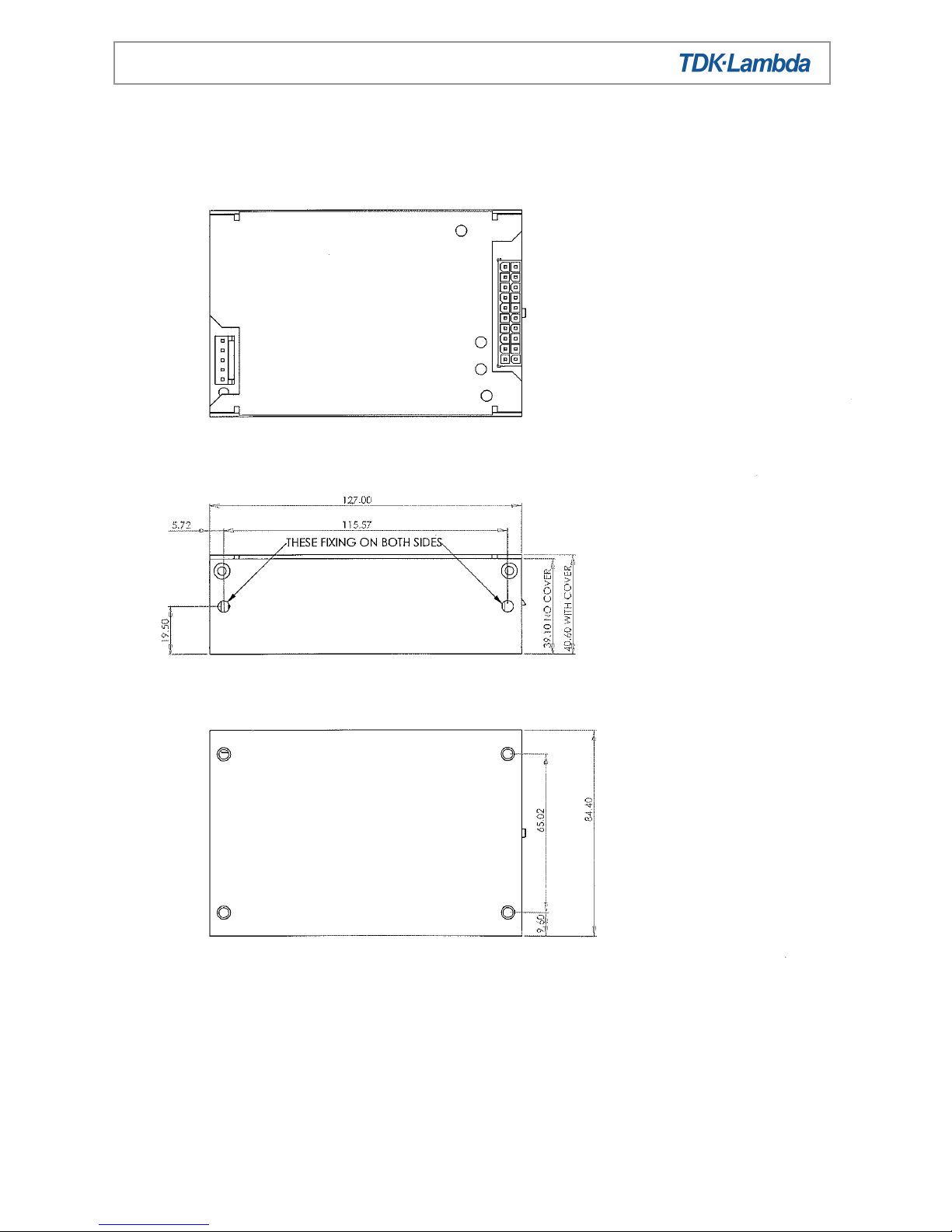
NVM175 Handbook
NVM175 Vertical Connector With Optional Case And Cover (-C Option)
NOTES
1 ALL CUSTOMER FIXINGS M3
MAXIMUM PENETRATION 4.5mm
MAXIMUM TORQUE 0.5 – 0.6Nm
2 ALL TOLERANCES +/-0.5mm
Page 21

Page 21 of 23 17814 issue 16, October 2018
NVM175 Handbook
NVM175 -K Option chassis
Page 22

Page 22 of 23 17814 issue 16, October 2018
NVM175 Handbook
NVM1D (with 18 way output connector which may be upright or right angled – only upright version
shown).
Page 23

Page 23 of 23 17814 issue 16, October 2018
NVM175 Handbook
NVM175 Screw Terminal (-S Option)
TDK-Lambda UK Ltd
Kingsley Avenue, Ilfracombe
Devon, EX34 8ES
Telephone - Sales and Service +44 (0)1271 856666
Head Office and Works +44 (0)1271 856600
Facsimile +44 (0)1271 864894
WEBSITE: www.uk.tdk-lambda.com
 Loading...