

TDK-Lambda FPS1000 Series, FPS1000-48, FPS1000-12, FPS1000-32, FPS1000-24 Instruction Manual
Page 1

FPS1000 INSTRUCTION MANUAL
Model FPS1000 FPS1000 FPS1000
V/I -24 -32 -48
24 32 48
29 38.4 58
33 26 17.25
40 31 21
V1 (V)
V2 (V)
I1 (A)
I2 (A)
V1
V2
Fig. 1: Rated output current vs output voltage
Vout (V)
I1
Iout (A)
I2
1V
2V
3V
4A
5W
6
Input voltage / frequency range
(*1) ---
7
Maximum input current (at 100/200Vac)
A
8 --9(*2) %
10 (*3) A
11 mS
12 (*5) --13 (*6) --14 (*4) mV
15 --16
PPM/°C
17 (*7)V
18 (*9) --19
Series operation
(*10)
--20 --21 (*8) V
22 --23 --24 --25 --26 --27 --28 --29 --30 --31 ---
32 --33 --34 --35 --36 --37 --38 --39 --40 --41
--42 --43 mA
44 Kg
45 ---
Rated output voltage
12
32
48
FPS1000 SERIES SPECIFICATIONS
FPS1000-12
FPS1000-32
FPS1000-48
Output voltage range
10.5~13.2
28.8~38.4
43~58
Output voltage set point
12+/-1%
32+/-1%
48+/-1%
Maximum output power
864
992
1008
Maximum Output Current (Refer to Fig.1)
72
31
21
85~265Vac continuous, 47~63Hz, Single phase
12.0/6.0
Power Factor (Typ)
>0.98 at 115/230V and maximum output power
Inrush current
Less than 40A
Efficiency (Typ)
84/86%
84/86%
85/88%
Hold-up time
20mS typical at 100Vac input, rated output voltage and less than 80% of rated load.
Maximum line regulation
0.40%
Max load regulation
0.80%
Output Ripple and noise pk-pk
200
250
300
Temperature stability
0.05% of rated Vout for 8hrs after 30min warm-up. Constant line, load and temperature.
Temperature coefficient
200
Remote sensing
Possible. Refer to Instruction Manual.
Parallel operation
Possible. Refer to Instruction Manual.
Possible. Refer to Instruction Manual.
Over current protection
105~125% of maximum output current. Refer to Fig. 1
Over voltage protection
31~34
41.5~45.5
62~66
Over temperature protection
Inverter shut down method, automatic reset.
Remote On/Off control
By electrical signal or dry contact. ON: 0~0.6V or short. OFF: 2~15V or open.
DC OK signal
Over-Temp. warning
Open collector signal. Refer to Instruction Manual
AC fail signal
Open collector signal. Refer to Instruction Manual
Auxiliary power supply
11.2~12.5VDC. 0.25A Maximum output current.
Vout voltage trimming
Front panel indicators
I
2
C Interface
Operating temperature-models without IEC inlet
models with IEC inlet
Possible, via Vout Trim pin in the I/O connector. Refer to Instruction Manual. AC OK, DC
OK, DC FAIL
Optional. Refer to Instruction Manual.
0~50°C:100% load. Derate 2%/°C, 50°C to 60°C. Derate 2.5%/°C, 60°C to 70°C
Storage temperature
Operating humidity
Storage humidity
Cooling
Vibration
Shock
Conducted emission
Radiated emission
Applicable safety standards
Withstand voltage
Insulation resistance
Leakage current
Weight (Typ)
Size (W*H*D)
Notes:
*1: For cases where conformance to various safety standards (UL, EN etc.) is required,
to be described as 100-240Vac (50/60Hz).
*2: At 100/200Vac, rated load and 25
˚C ambient temperature.
*3: Not applicable for the noise filter inrush curr
ent less than 0.2mS.
*4: Measured with JEITA RC-9131A 1:1 probe, 20MHz B.W.
*5: From 85~132Vac or 170~265Vac, constant load.
*6: From No-load to Rated load, constant input voltage. Measured at the sensing point in Remote sense.
*7: Remote sensing can compensate up to 1V drop on each load wire.
*8: Inverter shut down method. Reset by AC voltage recycle or by On/Off control.
*9: Derate Maximum output power by 10% for input voltage less than 100V
RMS
.
*10 For FPS 1000-12/P(S), when used not with FPS-S1U or FPS-T1U
racks, an EMI suppressor clamp should be attached to the AC cable,
as close as possible to the AC inlet, to meet class B.
24
FPS1000-24
21.5~29
24+/-1%
960
40
FPS1000
-12
12
13.2
66
72
81/83%
150
14.3~15.7
0~50°C: 100% load. Derate 2%/°C, 50°C to 60°C.
-30~85°C
10~90% RH, no condensation.
10~95% RH, no condensation.
By internal Fans. Variable speed control.
Built to meet ETS 300 019
Built to meet ETS 300 019
EN55022B, FCC part 15J-B, VCCI-B
EN55022B, FCC part 15J-B, VCCI-B
UL60950-1, EN60950-1
Input-Output: 3000Vrms, 1min. Input-Ground: 2000Vrms, 1min. Output-Ground:
500Vrms,1min.
More than 100Mohm at 25°C and 70% RH. Output-Ground: 500Vdc
Less Than 1.1mA at 230Vac
2.0
127x41x290mm. Refer to Outline Drawing.
---
Open collector signal. On when Vout ≥ 80+/-5% rated output. Max.sink current: 10mA
Page 2
Page 3
Page 4
FPS1000 SAFETY INSTRUCTIONS
SAFETY APPROVALS
UL 60950-1 and CSA22.2 No.60950-1 - UL Recognized. C-UL for Canada.
IEC 60950-1 - CB Report and Certicate.
EN 60950-1 - CE mark.
Marking by the CE Symbol indicates compliance to the Low Voltage Directive of the European Union.
A “Declaration of Conformity” in accordance with the preceding directives and standards has been made and is on le at our EU
representative TDK LAMBDA UK, located at Kingsley Avenue, Ilfracombe, Devon EX34 8ES, UK.
A “Declaration of Conformity” may be accessed via company website www.uk.tdk-lambda.com/technical-data
CAUTION: The following safety precaution must be observed during all phases of operation, service and repair of this equipment.
Failure to comply with the safety precautions or warnings in this document violates safety standards of design, manufacture and
intended use of this equipment and may impair the built-in protections within. TDK Lambda shall not be liable for user’s failure to
comply with these requirements.
Vorsicht: Die folgenden Sicherheitsvorschriften müssen vor Inbetriebnahme und in jedem Betriebszustand bei Service oder
Reparatur beachtet werden. Missachtung der Sicherheitsvorschriften und Warnhinweise aus diesem Handbuch führen zur
Verletzung der bestehenden Sicherheitsstandards. Bei Betrieb des Gerätes ausserhalb dem bestimmungsgemässen Einsatz
können die im Gerät integrierten Schutzfunktionen beeinträchtigt werden. TDK-Lambda ist nicht haftbar für Schäden, die durch
Missachtung dieser Sicherheitsvorschriften entstehen können.
CAUTION: FPS1000 units are not authorized for use as critical component in nuclear control systems, life support systems or
equipment for use in hazardous environments without the express written approval of the managing director of TDK-Lambda.
Vorsicht: Dieses Produkt ist nicht für die Verwendung als kritische Komponente in nuklearen Steuerungssystemen,
lebenserhaltenden Systemen oder Geräte für den Einsatz in gefährlichen Umgebungen, ohne die ausdrückliche schriftliche
Genehmigung durch TDK-Lambda zugelassen.
INSTALLATION (OVERVOLTAGE) CATEGORY& ENVIRONMENTAL CONDITIONS
The FPS1000 units have been evaluated to Overvoltage category II.
The FPS1000 units intended for use in the following operation conditions:
* Indoor use * Pollution degree 2 * Max. operational altitude: 3000m above sea level
*Ambient temperature: -10°C-50°C at 100% load, up to 70°C with output de-rating applied (See Specication)
GROUNDING
FPS1000 units are Class I product. To minimize electrical shock hazard, the FPS1000 units must be connected to an electrical ground.
The instruments must be connected to the AC power supply mains through a three conductor power cable, with the ground wire
rmly connected to an electrical ground (safety ground) at the power outlet. For instruments designed to be hard-wired to the supply
mains, the protective earth terminal must be connected to the safety electrical ground before any other connection is made. Any
interruption of the protective ground conductor or disconnection of the protective earth terminal will cause a potential shock hazard
that might cause personal injury.
Erdungskonzept: Dieses Produkt ist ein Gerät der Schutzklasse 1. Zur Vermeidung von gefährlichen Energieinhalten und
Spannungen, ist das Gehäuse an eine Schutzerde anzuschliessen. Der PE-Anschluss ist an einen festen Erder anzuschliessen. Bei
Festverdrahtung des Gerätes ist sicherzustellen, dass der PE Anschluss als erstes angeklemmt wird Jede mögliche Unterbrechung
des PE-Leiters oder Trennung der PE Verbindung kann einen möglichen elektrischen Schlag hervorrufen, der Personenschäden zur
Folge hätte.
LIVE CIRCUITS
Operating personnel must not remove the FPS1000 units cover. No internal adjustment or component replacement is allowed by nonTDK Lambda qualied service personnel. Never replace components with power cable connected. To avoid injuries, always disconnect
power, discharge circuits and remove external voltage sources before touching components. Restricted Access Area: FPS1000 units
should only be installed in a Restricted Access Area. Access should be available to service personnel only
Spannungsführende Teile
Die Geräteabdeckung darf nicht durch Endanwender geönet werden. Interne Modikationen, sowie Bauteileaustausch ist nur
durch TDK-Lambda qualiziertes Personal erlaubt. Vor Austausch von Bauteilen ist das Netzkabel bzw. die Versorgungsspannung
zu trennen. Energieversorgungsanschlüsse sind immer zu trennen, um Personenschäden durch gefährliche Energieinhalte und
Spannungen auszuschliessen. Die Stromkreise sind zu entladen, externe Spannungsquellen sind zu entfernen, bevor auf Bauteile bzw.
Komponenten Ebene gearbeitet wird.
Page 5

SYMBOLS
CAUTION Risk of Electrical Shock.
Instruction manual symbol. The instrument will be marked with this symbol when it is necessary for the user
to refer to the instruction manual.
Indicates hazardous voltage.
Indicates ground terminal.
Protective Ground Conductor Terminal
Denotes hazard. An attention to a procedure is called. Not following the procedure correctly could result in
personal injury. A WARNING sign should not be skipped and all indicated conditions must be fully understood
and met.
Denotes hazard. An attention to a procedure is called. Not following the procedure correctly could result in
damage to the equipment.
PARTS SUBSTITUTIONS & MODIFICATIONS
Parts substitutions and modications are authorized TDK Lambda service personnel only. For repairs or modications, the
instrument must be returned to TDK Lambda service facility.
AC INPUT
Do not connect FPS1000 units to mains supply exceeding the input voltage and frequency rating. The input voltage and
frequency rating is: 100-240V~, 50/60Hz. For safety reasons, the mains supply voltage uctuations should not exceed +/-10%
of nominal voltage.
ENERGY HAZARD
The main output of FPS1000 units is capable of providing hazardous energy. Due to hazardous energy level the output
and connections therefore must not be user accessible. Manufacturer's nal equipment must provide protection to service
personnel against inadvertent contact with output bus bars.
FUSE
Internal fuse is sized for fault protection and if a fuse was opened it would indicate that service is required. Fuse replacement
should be made by qualied technical personnel.
FPS1000 unit’s fuse ratings are described below. F101: F20A H 250Vac; F102: 6.3A 400VDC.
SICHERUNGEN: Vor Anschluss an die Netzversorgung ist die Aufstellanleitung zu beachten!
1. Absicherung: F101: F20A H 250VAC; F102: 6.3A 400VDC
2. Die Gehaeuseabdeckung darf nur im stromlosen Zustand geoeffnet werden.
ACHTUNG: Sicherungen duerfen nur durch geschulte Service Personen getauscht werden.
OVERCURRENT PROTECTION:
A readily accessible branch circuit over-current protective device rated 20A max. must be incorporated in the building wiring.
Überstromschutz
Eine leicht zugängliche Vorsicherung mit 20A max. pro Eingang muss in der Hausinstallation vorgesehen
werden
Page 6

Page 7

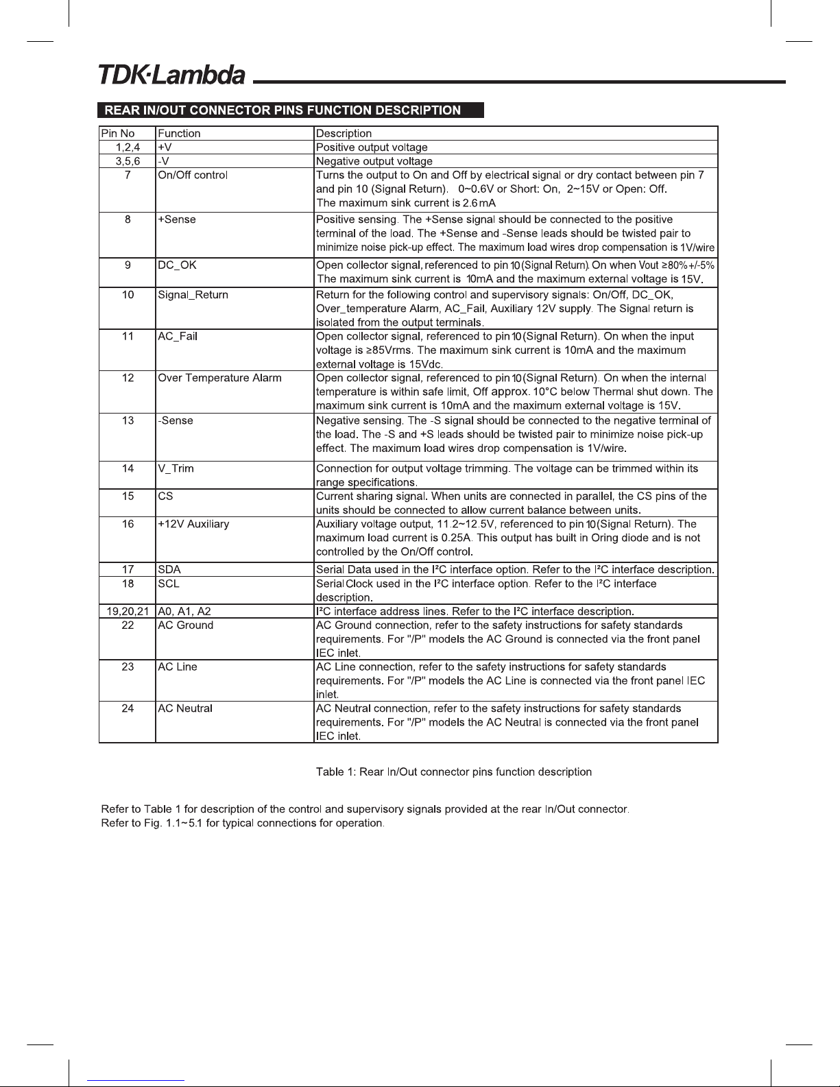
FPS 1000 CONNECTIONS FOR OPERATION
1.1. Remote sensing*
Fig 1-1
1. SINGLE UNIT OPERATION
LOAD
FPS1000
SIGNAL
RTN
ON/
OFF
+V
+S
-S
-V
8
13
710
Sense lines
Twisted pairs
Load line.
Up to 1V drop.
Load line.
Up to 1V drop.
1,2,4
3,5,6
Fig 1-2
Note: AC_FAIL, DC_OK and TEMP.ALARM are open collector signals. See Ta ble 1
1.4. Supervisory signals
1.3. On/off control
Fig 1-3
ON OFF
FPS1000
ON/OFF
7
SIGNAL_RTN
10
1.2. Output voltage trimming
FPS1000
+S
V_TRIM
-S
8
14
13
R1
R2
FPS1000
12V AUX
AC_FAIL
DC_OK
TEMP.ALARM
SIGNAL_RTN
Application
Monitoring
and Control
circuts
10K 10K
10K
Fig 1-4
16
11
9
12
10
+V
-V
In Local sense applications, the +/- sense have to be connected to the
+/-V terminals of the FPS1000 units prior the operating the FPS1000 units
*
0.0324
+V
-V
FPS1000-48
FPS1000-12
FPS1000-24
FPS1000-32
0.0324 1.1298 9.9342
Page 8

2.1. Remote sensing and current balance
2. PARALLEL OPERA TION
Fig 2-1
For best accuracy and current balance, each unit should be trimmed separately as shown
in Fig 1-2. The parallel units can be trimmed also by a single trimmer as shown in Fig 2-2.
2.2. Output voltage trimming
LOAD
FPS1000 #1
SIG.
RTN
ON/
OFF
+V
+S
-S
-V
CS
+S
-S
FPS1000 #2
SIG.
RTN
ON/
OFF
+V
+S
-S
-V
CS
+S
-S
+S
-S
FPS1000 #N
SIG.
RTN
ON/
OFF
+V
+S
-S
-V
CS
+S
-S
+V
-V
71015
71015
71015
Fig 2-2
FPS1000 #1
SIG.
RTN
ON/
OFF
V TRIM
+S
-S
CS
SIG.
RTN
ON/
OFFCS
FPS1000 #N
SIG.
RTN
ON/
OFFCS
FPS1000 #2
V TRIM
+S
-S
V TRIM
+S
-S
V TRIM
V TRIM
+S
-S
R
1
R
2
710
710
710
15
15
15
Derate the total output current by 10% when using
parallel operation to prevent overload condition.
The built-in Oring diodes on the main output and
the 12V Auxiliary output allow N+1 operation.
For input voltages less than 100Vac, maximum
output Power derated by 10% of the Power rating.
Up to 8 FPS1000 units of the same output voltage
rating can be connected in parallel. By connecting
the CS signal between the paralleled units,
automatic current balance is achieved,
with +/-10% accuracy.
-V
+V
FPS1000-48
FPS1000-24
FPS1000-32
FPS1000-12
0.0324 1.1298 9.9342
Page 9

2.3. On/off control
On/off control can be made via separate control for individual units (refer to Fig 1-3), or via
single control as shown in Fig 2-3.
3. SERIES OPARATION
(*) Diodes are user supplied
LOAD
FPS1000 #1
SIG.
RTN
ON/
OFF
FPS1000 #2
SIG.
RTN
ON/
OFF
+V
+S
-S
-V
+S
-S
+V
-V
+V
+S
-S
-V
(*)
(*)
710
710
Up to 3 units can be used for increased output voltage
It is recommended that diodes be connected in parallel with each unit output to prevent revese
voltage. Each diode should be rated to at least the power supply rated output voltage and
output current.
Fig 3-1
ON OFF
FPS1000 #1
SIG.
RETURN
ON/OFF
FPS1000 #2
SIG.
RETURN
ON/OFF
FPS1000 #N
SIG.
RETURN
ON/OFF
7
10
7
10
7
10
Fig 2-3
CAUTION
Series operation is not applicable for units with I
2
C bus option.
Page 10

Pull-up resistor can be tuned depending on the application bus.
Refer to next page “PULL-UP RESISTOR SELECTION”.
Pull-up resistor can be tuned depending on the application bus.
Refer to next page “PULL-UP RESISTOR SELECTION”.
should
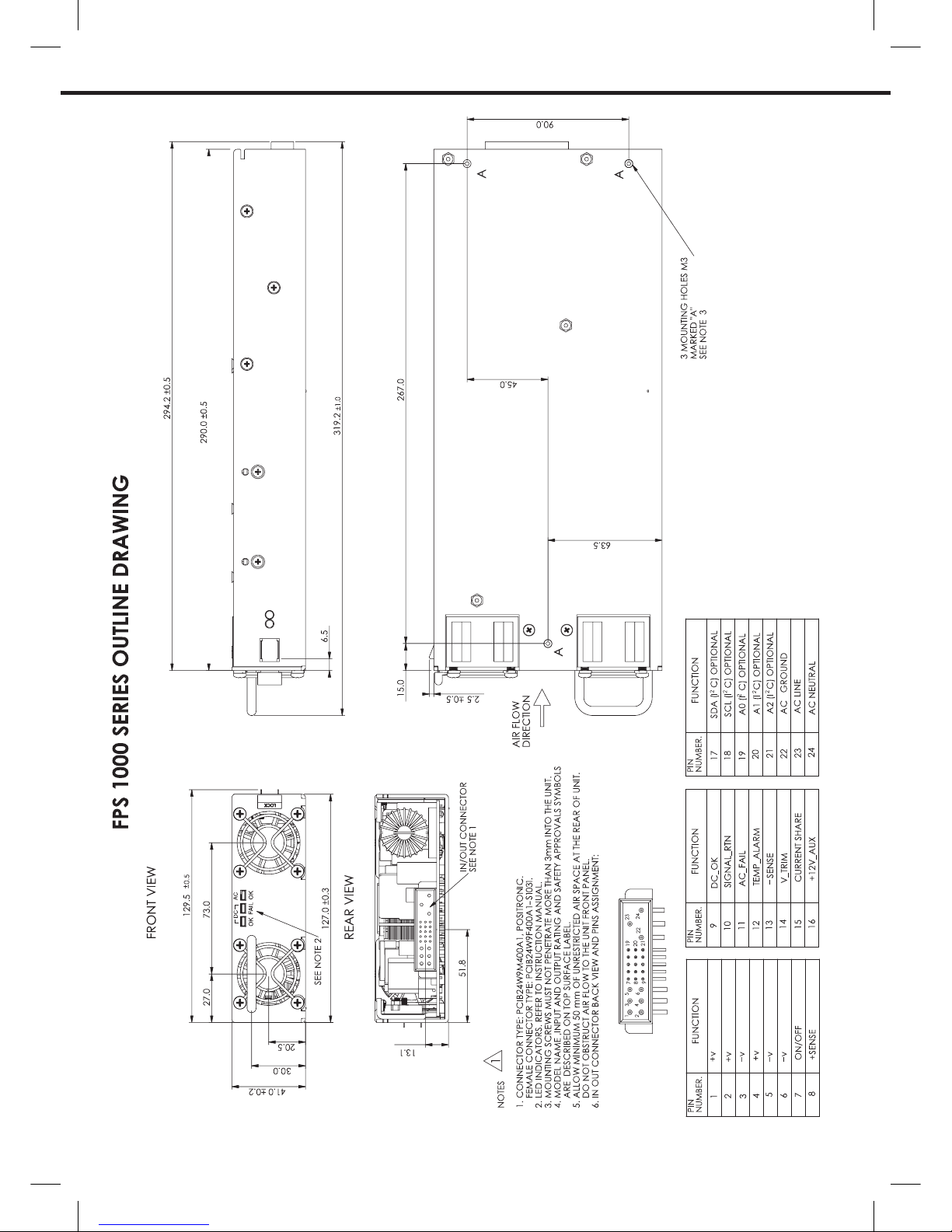
5. MOUNTING METHOD.
1. Forced air cooling allow minimum 50mm of unrestricted air space at the rear of the unit
do not obsruct air flow to the unit front panel
2. Mounting screws must not penetrate more than 3mm into the unit.
Fig 5-1
More
than
50mm
More
than
50mm
3 mounting holes M3
Marked “A”
see note 2
Air flow direction
Front side
see note 1
1. AC OKGreen LED: On when input voltage ≥ 85Vac, Off when Input voltage < 85Vac
2. DC OK Green LED: On when output voltage Vout ≥ 80% +/-5% of Vo rated
Off when output voltage Vout < 80% +/-5% of Vo rated
3. DC FAIL Red LED: On when output voltage Vout ≤ 80% +/-5% of Vo rated
Off when output voltage Vout > 80% +/-5% of Vo rated
4. FRONT PANEL INDICATORS.
Page 11

PULL-UP RESISTOR SELECTION
Figure 1 shows the internal section of I2C used in FPS series. There are 3 I2C ICs. Only one is shown as an example.
Maximum Pull up resistor can be between 12k ohm to 5k ohm depending on how many units are connected in the rack.
Ex - If one unit is connected, pull up resistor value can be 12k ohm max
If eight units are connected, pull up resistor value can be 5k ohm max
(Total capacitance of eight supplies will be 25 x 8 =200 pF + 50pF = 250pF).
Input voltage < 85Vac
< 80% +/-5% of Vo rated
For minimum pullup resistor selection, use the following equation,
V
DD
in FPS is 5V. VOL (max) is 0.4V & IOL is 3mA. So R
P (min)
is 1.53 kOhm
Each of the 3 ICs adds some capacitance to the bus. The total capacitance generated by the 3 ICs in each power supply is about 25pF.
Considering about 50pF extra capacitance for parasitic capacitance, wire capacitance and capacitance of master, the total capacitance
seen with 1 supply can be about 75pF.
Please use figure 2 for selecting the external pull up resistor.
IC
FPS SDA
PIN #17
PIN #18
-S
PIN #13
22Ω
200Ω
Fig. 1 Fig. 2
SCL
R
P (min)
=
V
DD-VOL
(max)
I
OL
Page 12

IA599-04-01I
Model: FPS1000-48 /S
Measurements and calculation examples
Output voltage readback
1. Output voltage (at the output terminals): 48.0V
2. Voltage before the "Oring" diode: 48.0V+0.5V=48.5V
3. Hex readback: CE (1100 1110).
4. Convert the hex readback to decimal: 206
5. Calculate measured Vout: Vout=206*0.2344=48.286V
FPS1000-24/S
A/D so that on every read data from each channel is read. Note that on each read. a conversion is started for a particular
channel and the result which will be displayed and will be of the previous read. (i.e. the previous channel).
Thus second read cycle gives result of the actual channel.
Note: the first result from a sequence of reads should not be considered.
FPS1000-48/S
FPS1000-32/S
FPS1000-12/S
0~15V
0~80A
0~100°C
0.0586 V/Bit
0.312 A/Bit
0.391°C/Bit
 Loading...