

Page 1

TDK-Lambda
DRJ120, 240 Series
INSTRUCTION MANUAL
DRJ120, 240 Series
Instruction Manual
BEFORE USING THE POWER SUPPLY UNIT (Common)
Be sure to read this instruction manual thoroughly before using this product. Pay attention to all cautions
and warnings before using this product. Incorrect usage could lead to an electrical shock, damage to the unit
or a fire hazard.
DANGER
Never use this product in locations where flammable gas or ignitable substances are present.
INSTALLATION WARNING
• When installing, ensure that work is done in accordance with the instruction manual. When installation is
improper, there is a risk of electric shock and fire.
• Installation shall be done by Service personnel with necessary and appropriate technical training and
experience. There is a risk of electric shock and fire.
• Do not cover the product with cloth or paper etc. Do not place anything flammable around. This might
cause damage, electric shock or fire.
WARNING on USE
• Do not touch this product or its internal components while circuit in operation, or shortly after shutdown.
You may receive a burn.
• While this product is operating, keep your hands and face away from it as you may be injured by an
unexpected situation.
• There are cases where high voltage charge remains inside the product. Therefore, do not touch even if
they are not in operation as you might get injured due to high voltage and high temperature.
You might also get electric shock or burn.
• Do not make unauthorized changes to this product nor remove the cover as you might get an electric
shock or might damage the product. We will not be held responsible after the product has been modified,
changed or dis-assembled.
• Do not use this product under unusual condition such as emission of smoke or abnormal smell and sound
etc. Please stop using it immediately and shut off the product.
It might lead to fire and electric shock. In such cases, please contact us. Do not attempt repair by yourself,
as it is dangerous for the user.
• Do not operate and store these products in environments where condensation occurs due to moisture and
humidity. It might lead fire and electric shock.
• Do not drop or apply shock to this product. It might cause failure. Do not operate these products
mechanical stress is applied.
CAUTION on MOUNTING
• Confirm connections to input/output terminals are correct as indicated in the instruction manual before
switching on.
• Input/output lines, please use the wires as short and thick as possible.
• Do not use this product in special environment with strong electromagnetic field, corrosive gas or
conductive substances and direct sunlight, or places where product is exposed to water or rain.
• Mount this product properly in accordance with the instruction manual, mounting direction and shall be
properly be ventilated.
1/14
PA637-04-01B
Page 2

TDK-Lambda
DRJ120, 240 Series
• Please shut down the input when connecting input and output of the product.
• When installing in environment where conductive foreign, dust and liquid may be present,
please consider penetration of above foreign material in the power supply by installing filter, to prevent
trouble or malfunction.
CAUTION on USE
• Product individual notes are shown in the instruction manual. If there is any difference with common
notes, individual notes shall have priority.
• Before using this product, be sure to read the catalog and instruction manual. There is a risk of electric
shock or damage to the product or fire due to improper use.
• Input voltage, Output current, Output power, ambient temperature and ambient humidity should be kept
within specifications, otherwise the product will be damaged, or cause electric shock or fire.
• If the built-in fuse is blown, do not use the product even after replacing the fuse as there is a risk of
abnormality inside. Be sure to request repair to our company.
• For products without built-in protection circuit (element, fuse, etc.), insert fuse at the input to prevent
smoke, fire during abnormal operation.
As for products with built-in protection circuit, depending on usage conditions, built-in protection circuit
might not work. It is recommended to provide separate proper protection circuit.
• For externally mounted fuse do not use other fuses aside from our specified and recommended fuse.
• This product was made for general purpose electronic equipment use and is not designed for applications
requiring high safety (such as extremely high reliability and safety requirements. Even though high
reliability and safety are not required, this product should not be used directly for applications that have
serious risk for life and physical safety). Take sufficient consideration in fail-safe design (such as
providing protective circuit or protective device inside the system, providing redundant circuit to ensure
no instability when single device failure occurs).
• When used in environments with strong electromagnetic field, there is possibility of product damage due
to malfunction.
• When used in environment with corrosive gas (hydrogen sulfide, sulfur dioxide, etc.), there is possibility
that they might penetrate the product and lead to failure.
• When used in environments where there is conductive foreign matter or dust, there is possibility of
product failure or malfunction.
• Provide countermeasure for prevention of lightning surge voltage as there is a risk of damage due to
abnormal voltage.
• Connect together the frame ground terminal of the product and the ground terminal of the equipment
for safety and noise reduction. If these ground is not connected together, there is a risk of electric shock.
• Parts with lifetime specifications (built-in fan, electrolytic capacitor) are required to be replaced
periodically. Set the overhaul period depending on the environment of usage and perform maintenance.
If maintenance is not performed, there is possibility of product failure or malfunction.
Also, note that there are cases when EOL products cannot be overhauled.
• Take care not to apply external abnormal voltage to the output. Especially, applying reverse voltage or
over voltage more than the rated voltage to the output might cause failure, electric shock or fire.
• This product has possibility that hazardous voltage may occur in output terminal depending on failure
mode. The output of these products must be protected in the end use equipment to maintain SELV.
• This product contains a printed circuit board utilizing surface mounted devices.
PCB stress such as bending, twisting, etc., could cause damage. Please handle with care.
INSTRUCTION MANUAL
2/14
PA637-04-01B
Page 3

TDK-Lambda
DRJ120, 240 Series
NOTE
• Take note that traces of sheet metal processing be left in our power supplies.
• When disposing product, follow disposal laws of each municipality.
• Published EMI (CE, RE) and immunity are the result when measured in our standard measurement
conditions and might not satisfy specification when mounted and wired inside end-user equipment.
Use the product after sufficiently evaluating at actual end-user equipment.
• When exporting our products, apply for necessary permissions as required by rules and regulations of
Foreign Exchange and Foreign Trade Control Act.
• Catalogue, contents of the instruction manual may be changed without a prior notice.
Refer to latest catalogue or instruction manual.
• Reproduction or reprinting the instruction manual or its portion is forbidden without our permission.
• CE Marking
CE Marking, when applied to a product covered by this handbook, indicates compliance with the low
voltage directive.
STORAGE METHOD and STORAGE PERIOD
• Store in original package
• Prevent excessive vibration, impact and external force from being applied during storage.
• Store in an area out of direct sunlight
• Temperature and humidity should be within range of product specification (with no condensation)
• Storage period should be up to two years from receiving.
INSTRUCTION MANUAL
3/14
PA637-04-01B
Page 4

1. Model Name Identification Method
DRJ 120 – 24 – 1 /□
Option (*1)
Single phase AC input
Rated output voltage
Output power type
Series name
2. Terminal Explanation
DRJ120 DRJ120/E
TDK-Lambda
DRJ120, 240 Series
INSTRUCTION MANUAL
(*1) Blank : Block terminal type
/E : European terminal type
DRJ240 DRJ240/E
① +V : + Output terminal
② –V : – Output terminal
③ V.ADJ : Output voltage adjustment trimmer
The output voltage rises when trimmer is turned clockwise.
④ DC OK : Output monitoring indicator
Green LED lights when output voltage is turned on and within specification.
⑤ : Protective Earth (PE) terminal
Connect to safety ground of apparatus or equipment.
⑥ N : Input terminal
Neutral line
⑦ L : Input terminal
Live line (fuse in line)
* All terminal screws are M3.5.
4/14
PA637-04-01B
Page 5
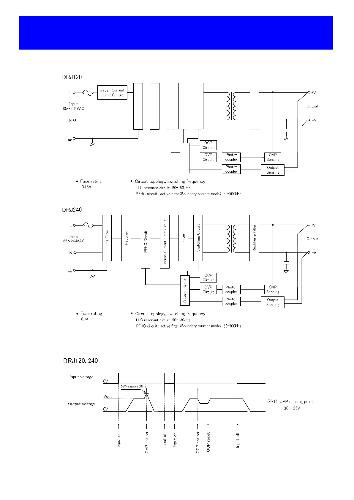
3. Block Diagram
TDK-Lambda
DRJ120, 240 Series
INSTRUCTION MANUAL
Rectifier
Line Filter
Filter
PFHC Circuit
Switching Circuit
Control Circuit
Rectifier & Filter
4. Sequence time chart
5/14
PA637-04-01B
Page 6

5. Connecting Method
Pay attention to the input wiring. If it is connected to wrong terminal, the product will be damaged.
Input must be off when making connections.
Connect terminal to earth by thick wire for safety and improvement of noise sensitivity.
When connecting or removing input and output wire, do not apply stress to PCB.
DRJ120, DRJ240
DRJ120/E, DRJ240/E
TDK-Lambda
DRJ120, 240 Series
INSTRUCTION MANUAL
Recommended torque: 1.0 – 1.6 N・m (10.2 – 16.3 kgf・cm)
6. Explanation of Functions and Precautions
6-1. Input Voltage Range
Input voltage range is single phase 85 – 264VAC (47 – 63Hz) or 120 – 370VDC. Input voltage which is out of specification may cause
product damage. For cases where conformance to various safety standards (UL, CSA, EN) required, input voltage range is 100 –
240VAC (50 – 60Hz). In case of using input voltage which is less than specification, output voltage might repeat start and stop.
Note : This series is able to withstand input of 300VAC for 5 seconds (No damage). Please note that to satisfy the
electrical characteristics, the input voltage range must be within 85-264VAC.
6-2. Output Voltage Range
Output voltage is set the rated value at shipment. Output voltage within 24 – 28V can be adjusted by V.ADJ trimmer.
In case of turning the trimmer clockwise, the output voltage will be increased. Take note when the output voltage is increased
excessively, over voltage protection (OVP) function may trigger and output voltage will shut down. Furthermore, when increasing the
output voltage, reduce the output current so as not to exceed the maximum output power.
When the trimmer turns quickly at no load condition, the output voltage might not change quickly. In this case, flow the output current or
wait until the output voltage is stable, and then re-input.
Please turn the trimmer slowly during the output voltage adjustment.
6/14
PA637-04-01B
Page 7

TDK-Lambda
DRJ120, 240 Series
6-3. Inrush Current
DRJ120 is equipped with power thermistor to limit the inrush current. The higher current will flow at higher ambient temperature or
re-input condition. DRJ240 is equipped with a relay. Higher current may flow when input turn on interval is short. Please select input
switch and fuse carefully with the high temperature and re-input condition. The inrush current value is under cold start at 25C in the
specification. Please refer to section “10. External Fuse rating” for selection of external fuses.
6-4. Over Voltage Protection (OVP)
OVP function is shut down method and manual reset type.
OVP function operates within output is 30 – 35V. To reset the shut down by OVP, disconnect the input of power supply for minutes
then re-apply.
The setting value of OVP is fixed and it cannot adjust externally. Please be aware that it might cause damage when a voltage is applied
from the outside to the output terminal. In case of using inductive load, please put protective diode in series to the output power line.
6-5. Over Current Protection (OCP)
The OCP function is hiccup mode with automatic recovery. OCP function operates when the output current exceeds 101% of peak DC
output current of specification. The output will be automatically recovered when the overload condition is removed. Do not operate the
product under over current or shorted conditions which might cause damage. The setting value of OCP setting is fixed and it cannot
adjust externally.
6-6. Peak Output Current
Use these products so that relationship among duty, rms output current (Irms) and peak output current (Ip) satisfy conditions defined by
expression below. Also peak output current pulse width (τ) should be 10 seconds or less, Duty should be 35% or less.
Ip :
Peak output current (A)
Irms :
RMS output current (A)
Imin :
Minimum output current (A)
τ :
Peak current pulse width (sec)
T :
Period (sec)
INSTRUCTION MANUAL
Peak current pulse width (τ) :
Peak output current (Ip) :
RMS output current (Irms) :
Duty = τ / T × 100 % :
[ Ip2 × D + Imin2 × (1-D) ] ½ :
Within 10 seconds
Within the rated peak output current (120%)
Within the rated rms output current
DRJ120 : 100% or less
DRJ240 : 75% or less
≤ 35 %
≤ Irms
of maximum output current
of maximum output current
6-7. Output Ripple & Noise
The standard specification for maximum ripple value is measured according to measurement circuit as below. When load lines are
longer, ripple voltage becomes larger. In this case, electrolytic capacitor, film capacitor, etc., might be necessary to use across the load
terminal. The output ripple cannot be measured accurately if the probe ground lead of oscilloscope is too long.
C1: 0.1uF Cap., Film
C2: 47uF Cap., Elect.
7/14
PA637-04-01B
Page 8

TDK-Lambda
DRJ120, 240 Series
6-8. Series Operation
For series operation, either method (A) or (B) is possible.
Method (A)
Power
Supply
Power
Supply
+V
-V
+V
-V
+
Load
-
Method (B)
+V
Power
Supply
-V
+V
Power
Supply
-V
In case of method (A), please connect bypass diode to prevent reverse voltage.
Please select a bypass diode with maximum forward current rating more than output load current.
And maximum reverse voltage must withstand each power supply output voltage.
6-9. Parallel Operation
(A) Operation to increase the Output Current is not possible.
(B) Operation as a Backup Power Supply is possible as follows.
1. Set the power supply output voltage higher by the amount of forward voltage drop (VF) of the diode.
2. Please adjust the output voltage of each power supply to be the same.
3. Please use within the specifications for output voltage and output power.
4. Please select a reverse current prevention diode with maximum forward current rating more than output
load current. And maximum reverse voltage must withstand each power supply output voltage.
(A) (B)
Power
Supply
Power
Supply
+V
+V
-V
-V
+
Load
-
+V
Power
Supply
-V
+V
Power
Supply
-V
6-10. Isolation Test
Isolation resistance between output and terminal is more than 100 MΩ at 500 VDC. For safety operation, voltage setting of DC
isolation tester must be done before test. Ensure that the product is fully discharged after the test.
Output - terminal : More than 100MΩ at 500 VDC
INSTRUCTION MANUAL
+
-
+
-
+
Load
-
Load
Load
8/14
PA637-04-01B
Page 9

TDK-Lambda
DRJ120, 240 Series
6-11. Withstand Voltage
This series is designed to withstand 3.0kVAC between input and output, 1.77kVAC between input and terminal and 500VAC
between output and terminal for 1 minute. When test a withstand voltage, set current limit of withstand voltage tester at 20 mA (for
between output and terminal: 100 mA). The applied voltage must be gradually increased from zero to testing value and then
gradually decreased for shut down. When timer is used, the power supply might be damaged by high impulse voltage at timer switch on
and off timing. Please connect input and output as follows.
Input - Output (dotted line) : 3.0kVAC (1 min, 20 mA)
Input - terminal (solid line) : 1.77kVAC (1 min, 20 mA)
Output - terminal : 500VAC (1min, 100mA)
INSTRUCTION MANUAL
Note 1: This series has monolithic ceramic capacitor in between secondary circuit and terminal.
Some of the withstand voltage tester may generate high voltage at the matching with monolithic ceramic capacitor and might
cause the product damage. Please check the waveform of applied voltage before testing.
Note 2: In case of using external noise filter, capacitance between input and terminal might be increased.
When in testing withstand voltage between input and output, there is a possibility exceeding withstand voltage between output
and terminal. Please check the voltage between output and terminal.
If the voltage exceeds withstand voltage specification, please add external capacitor between output and terminal. It can
decrease the generate voltage. On the other hand, no need to check the voltage in case of output and terminal is shorted.
The example of noise filter circuit that may increase capacitance
between input and .
(Capacitance in dashed line is added.)
The dashed line is external capacitor adding point or short point.
Even in the case of +V and , that is a similar effect.
9/14
PA637-04-01B
Page 10

Load (%)
Mount ing
Mount ing
Mount ing
Output
terminal
In
put terminal
In
put terminal
Output
terminal
Output terminal
In
put terminal
7. Mounting Directions
7-1. Mounting Directions
The standard mounting is direction (A) and other possible mounting directions are (B) and (C).
Mounting (A)
Mounting (B)
TDK-Lambda
DRJ120, 240 Series
INSTRUCTION MANUAL
Mounting (C)
Name plate
7-2. Output Derating according to Ambient Temperature
Refer to the below derating curve.
Do not exceed the load derating. Load (%) is percent of maximum output power or maximum output current.
DRJ120, DRJ120/E (AC input & DC input : 120VDC ≤ x ≤ 300VDC)
120
100
80
60
40
Load (% )
20
0
-30 -20 -10 0 10 20 30 40 50 60 70 80
Ambient temperature (°C)
-25 - 25 100 100 100
Mounting (A) & (B)
Mounting (C)
Ta
Mounting
(°C)
55 100 100 100
65 66 66 50
70 50 50 -
(A)
DRJ120, DRJ120/E (DC input : 300VDC < x ≤ 370VDC)
120
100
80
60
Load (%)
40
20
0
-30 -20 -10 0 10 20 30 40 50 60 70 80
Ambient temperature (°C)
-25 - 50 100 100 1 00
Mount ing (A) & (B) & (C)
T a
(°C)
(A)
Load (%)
Mounting
(B)
(B)
Mounting
(C)
(C)
10/14
PA637-04-01B
Page 11

Load (%)
Mount ing
Mount ing
Mount ing
DRJ240, DRJ240/E (AC input & DC input : 120VDC ≤ x ≤ 370VDC)
TDK-Lambda
DRJ120, 240 Series
INSTRUCTION MANUAL
120
100
80
60
Load (%)
40
20
0
-30 -20 -10 0 10 20 30 40 50 60 70 80
Ambient temperature (°C)
-25 - 25 100 100 100
Mount ing (A)
Mount ing (B)
Mount ing (C)
T a
(°C)
40 100 100 77.5
55 100 70 55
65 66 50 40
70 50 40 -
(A)
(B)
7-3. Surrounding Space
Refer to the below table to provide sufficient distance (X, Y, Z) when unit is mounted with other devices.
This series is convection cooling type power supply. When unit mounted with other device on top / bottom, please consider the heat
radiation and safety.
X X
Y
Z
Surrounding space definition : Mounting (A)
Surrounding space definition : Mounting (B)
Surrounding space definition : Mounting (C)
X Y Z
DRJ120 ≥ 5 mm ≥ 40 mm ≥ 20 mm
DRJ240 ≥ 5 mm ≥ 40 mm ≥ 20 mm
X Y Z
DRJ120 ≥ 5 mm ≥ 40 mm ≥ 20 mm
DRJ240 ≥ 5 mm ≥ 40 mm ≥ 20 mm
X Y Z
DRJ120 ≥ 5 mm ≥ 40 mm ≥ 20 mm
DRJ240 ≥ 5 mm ≥ 40 mm ≥ 20 mm
(C)
11/14
PA637-04-01B
Page 12

TDK-Lambda
DRJ120, 240 Series
INSTRUCTION MANUAL
8. Wiring Method
(1) The input line and output load line shall be separated, and use all lines as thick and short as possible to make lower impedance.
The input line and output load line shall be twisted or use shielded wire to improve noise sensitivity.
(2) Noise can be eliminated by attaching a capacitor to the load terminals.
(3) EMI reduction performance by winding the cable around the appropriate ferrite core or clamp core.
(4) For safety and EMI considerations, connect terminal to ground terminal of the equipment.
(5) The recommended wire type, torque and crimp type terminal are shown as below:
Block terminal type
Model
DRJ120
DRJ240
Note 1: When using separate loads, use of two pcs. of 0.8 mm thick crimp type terminal is recommended.
Note 2: For recommended diameter, refer to wire manufacturer recommended allowable current and voltage drop.
Note 3: Use wires rating at least 105C and copper conductor only.
Note 4: Use crimp type terminal for connection to terminal.
Recommended
Wire
AWG 14 - 20
Recommended torque
All terminal M3.5 screws
1.0 – 1.6 N・m
(10.2 – 16.3 kgf・cm)(8.85– 14.2 lb・in)
European terminal type (/E Option)
Model
DRJ120/E
DRJ240/E
Note 5: Use wires rating at least 105C and copper conductor only.
Solid wire is possible to push in. In case of using stranded wire, connect by the following method.
Pushing the lever by tool such as a flat head screwdriver then insert the wire until its stripped part is not seen any more then remove tool.
After wiring, confirm that wire is connected to the terminal certainly.
Lack insertion of wiring or slack of wiring might cause electric shock, fire or damage of equipment.
Recommended
Wire
AWG 14 - 20 8 - 10 mm
Recommended Wire to be stripped
When removing the wire, remove them while pushing the lever by tool such as a flat head screwdriver.
Recommended crimp type terminal
D
(MAX)
6.8 mm
T
(MAX)
1.0 mm 1 piece
0.8 mm 2 pieces
Mounting piece
(MAX)
9. Internal Fuse Rating
Fuse is in live line.
This series uses time-lag fuse.
DRJ120, DRJ120/E : AC250V, 3.15A
DRJ240, DRJ240/E : AC250V, 6.3A
12/14
PA637-04-01B
Page 13

TDK-Lambda
DRJ120, 240 Series
INSTRUCTION MANUAL
10. External Fuse rating
Refer to the following fuse rating when selecting the external input fuse.
The surge current flows when input turn on. Use slow blow fuse or time lag fuse. Fast blow fuse cannot be used.
Fuse rating is specified by inrush current value at input turn on. Do not select the fuse according to actual input current (rms.) values.
DRJ120, DRJ120/E : 3.15A
DRJ240, DRJ240/E : 6.3A
11. Product mounting on DIN Rail
This series conforms to TS35 size of DIN standard. The width of mounting rail is 35 mm.
11-1. Mounting on DIN Rail
Make sure input and output wires are disconnected before mounting the product onto the rail.
(1) Tilt the product slightly back ward, fit the product over the
top hat rail.
(2) Press against the bottom front side for locking.
Shake the product to check the locking action.
11-2. Removal from DIN Rail
Switch main power off and disconnect your system from the supply network.
Pull the latch at the bottom of the product downwards and gently dismount the product from the rail.
Name plate
Name plate
13/14
PA637-04-01B
Page 14

TDK-Lambda
DRJ120, 240 Series
INSTRUCTION MANUAL
12. Before concluding that the product is at fault, perform the following checks:
(1) Check the rated input is correct applied.
(2) Check the input and output wiring are connected correctly.
(3) Ensure the wire size is not too thin.
(4) Check if the output voltage control (V.ADJ) is properly adjusted.
(5) Ensure the output current and output power is within its specifications.
(6) Audible noise can be heard under the following conditions:
(A) Input voltage waveform is not sinusoidal wave.
(B) At dynamic load operation.
(7) Ensure that large capacitor is not connected on the output side.
Please use within maximum capacitance shown below.
If connecting more than the following capacitance value is required, please contact us for details.
Maximum external capacitance
DRJ120 5000µF
DRJ240 10000µF
13. The life expectancy
The life of the power supply depends on the life of the built-in aluminum electrolytic capacitor. The life is described in reliability data.
The life of the aluminum electrolytic capacitor varies depending on the method of mounting the power supply, the load current, and the
ambient temperature. Please refer to “Electrolytic Capacitor Lifetime”. Please do not use the product which passed over the life
expectancy. There is a risk of unexpected output shutdown and specifications may not be satisfied.
Please contact us for maintenance or exchange the product which passed over the life expectancy.
14. Warranty Period
This product is warranted for a period of 3 years from the date of shipment. For damages occurring at normal operation within this
warranty period, repair is free of charge. Please read the General Safety Instruction before using the product.
15. This Series UL508 Listed Conditions
(1) Wire Requirement: minimum rated 105C & must be copper conductor only.
(2) For a use in a pollution degree 2 environment only.
(3) These products are considered for use where maximum surrounding temperature does not exceed 70 °C. When installing these
products, please refer to section 7-2 for derating.
(4) Indoor use only.
16. This Series IEC/EN 62477-1 Conditions
Wait for 1 min to avoid risk of electric shock
14/14
PA637-04-01B
 Loading...