

Page 1
TDK-Lambda
CUS100MB
INSTRUCTION MANUAL
BEFORE USING THE POWER SUPPLY UNIT
Be sure to read this instruction manual thoroughly before using this product. Pay attention to all cautions and warnings before
using this product. Incorrect usage could lead to an electrical shock, damage to the unit or a fire hazard.
DANGER
Never use this product in locations where flammable gas or ignitable substances are present. There are risks of igniting these
substances and exploding by an arcing.
WARNING
Do not touch this product or its internal components while circuit is live, or shortly after shut down. There may be high voltage
or high temperature present and you may receive an electric shock or burn.
When this product is operating, keep your hands and face away from it as you may be injured by an unexpected situation.
Do not make unauthorized changes to this product, otherwise you may receive an electric shock and void your warranty.
Do not drop or insert anything into this product. It might cause a failure, fire and electric shock.
Do not use this product under unusual condition such as emission of smoke or abnormal smell and sound etc. It might lead to
fire and electric shock. In such cases, please contact us. Do not attempt repair by yourself, as it is dangerous for the user.
Do not operate these products in the presence of condensation. It might lead fire and electric shock.
CAUTION
This power supply is designed and manufactured for use within an end product such that it is accessible to SERVICE
ENGINEERS only.
Confirm connections to input/output terminals are correct as indicated in the instruction manual before switching on.
Input voltage, Output current, Output power, ambient temperature and ambient humidity should be kept within specifications,
otherwise the product will be damaged.
Do not operate and store this product in an environment where condensation might occur. In such case, waterproof treatment is
necessary.
Do not use this product in environment with a strong electromagnetic field, corrosive gas or conductive substances.
For applications, which require very high reliability, it is necessary to provide a fail-safe mechanism in the end equipment.
Do not inject abnormal voltages into the output of this product. The injection of reverse voltage or over voltage exceeding
nominal output voltage into the output terminal might cause damage to internal components.
Never operate the product under over current or short-circuit conditions, or outside its specified Input Voltage Range.
Insulation failure, smoking, burning or other damage may occur.
This product contains a printed circuit board utilizing surface mounted devices. PCB stress such as bending, twisting etc. could
cause damage. Therefore, please handle with care.
When handling this product, hold the board edge and take care not to touch the component side. When installing this product
in apparatus or equipment, mount it on spacers.
This product has used Power Thermistor to protect the circuit from Inrush Current. Frequent repetition of input on/off might
cause damage to internal components because of generating surge current.
Breaking of internal fuse is considered internal failure. In such cases, please contact us.
The information in this document is subject to change without prior notice. Please refer to the latest version of the data sheet,
etc., for the most up-to date specifications of the product.
Double pole / neutral fusing.
No part of this document may be copied or reproduced in any form without prior written consent of TDK-Lambda.
Note : CE MARKING
CE marking, when applied to this series products, indicates compliance with the Low Voltage Directive.
<Page>
1/14 CA833-04-01A
Page 2
TDK-Lambda
CUS100MB
INSTRUCTION MANUAL
Important safety instructions
Servicing
These products are not customer serviceable. Repairs can only be carried out by TDK-Lambda or their authorized agents. These products are not
authorized for use as critical components in nuclear control systems, life support systems or equipment for use in hazardous environments without
the express written approval of the Managing Director of TDK-Lambda Corporation.
Safety Class of Protection
This power supply is a switch mode power supply for use in applications within a Pollution Degree 2, overvoltage category II environment.
Material Group IIIb PCB is used within it.
Input markings and symbols
Caution refer to supplementary documents
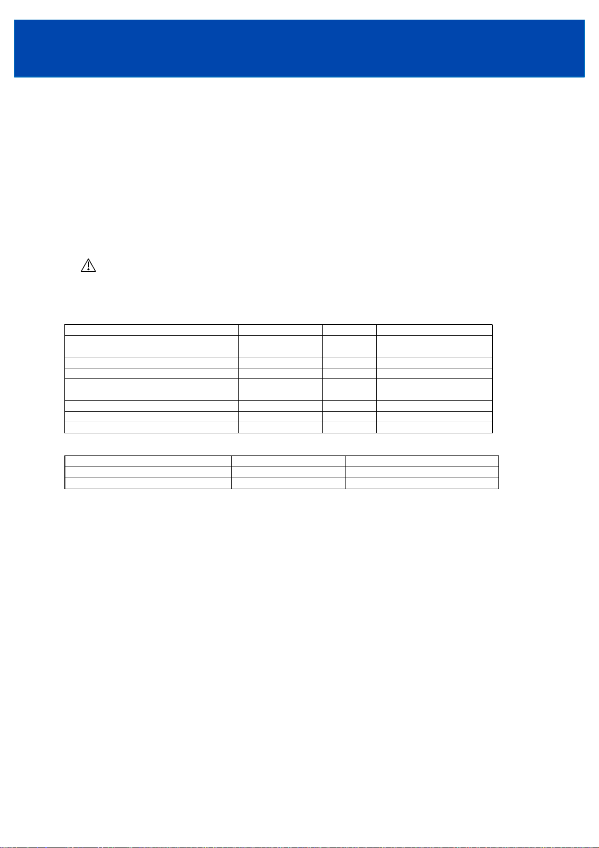
EMC performance
Immunity
Test Standard Passed Comments
Electrostatic discharge IEC61000-4-2 Level 3 Air discharge 8kV
Contact discharge 6kV
Electromagnetic field IEC61000-4-3 Level 3 10V/m
Fast / burst transient IEC61000-4-4 Level 3 2.0kV (100kHz)
Surge immunity IEC61000-4-5 Level 3
Level 4
Conducted RF immunity IEC61000-4-6 Level 3 10V
Power frequency magnetic field IEC61000-4-8 Level 4 30A/m
Voltage dips, variations, interruptions IEC61000-4-11 Pass
Emissions
Test Standard Comments
EMI EN55022 Class B (as per CISPR 22)
Conducted harmonics IEC61000-3-2 Meet Class A at 70% load or less (*1)
*1. Output power is less than 50W for 5V model and 70W for 12V~48V models.
Normal mode 2.0kV
Common mode 4.0kV
General installation instructions
1) CUS100MB is for installation in Class I end equipment only, and therefore must be reliably earthed and professionally
installed.
CUS100MB/G2 is optional model for installation in Class II end equipment, and no earthing connection to the power
supply is required.
2) These products are IPX0, and therefore chemicals/solvents, cleaning agents and other liquids must not be used.
3) The first protective earth connection in the final installation must be marked with the protective earth symbol.
Special Instructions for IEC/UL/ 60601-1
1) These products are designed for continuous operation within an overall enclosure, and must be mounted such that access to the mains terminals
is restricted. See Clause 16, IEC/UL60601-1.
2) These products are NOT suitable for use in the presence of flammable anaesthetic mixtures with air or with oxygen or with nitrous oxide.
3) These products are classed as ordinary equipment according to IEC/UL60601-1 and are NOT protected against the ingress of water.
4) Reference should be made to local regulations concerning the disposal of these products at out of their useful life.
5) These products have not been assessed to IEC/UL60601-1-2 (EMC) but EMC test data is available from TDK-Lambda Corporation.
6) For Class II installation (CUS100MB/G2), the product needs to be fixed such that they are isolated from unearthed accessible conductive parts
by at least 2 MOPP’s.
7) For IEC/EN 60601-1 2nd Edition, UL 60601-1 1st Edition, CSA-C22.2 No. 601.1-M90, these products have a reinforced insulation barrier
between input and output. For IEC/EN 60601-1 3rd Edition, ANSI/AAMI ES 60601-1, CSA 22.2 No 60601-1, these products provide
reinforced insulation between input and outputs of 2 MOPPs. 1 MOPP from input to earth and 1 MOPP from output to earth.
8) All outputs have basic spacing’s to earth rated for mains - 250Vac, and due consideration must be given to this in the end product design.
9) These products have SELV outputs.
<Page>
2/14
Page 3
1 Model name identification method
TDK-Lambda
CUS100MB
INSTRUCTION MANUAL
Option (*1)
Rated Output Voltage
Output Power type
Series Name
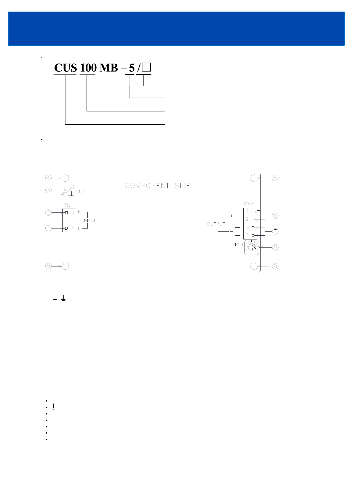
2 Terminal Explanation
③ is for standard model except for /A, /B and /G2 model.
④⑤⑨ are for standard model and /G2 model, except for /A and /B model.
For the Protective Earth of /A and /B model, please refer to 5-3-2 and 5-3-3.
(*1) Blank : Standard model
/A : With chassis and cover model
/B : With base plate model
/G2 : Class II model
① L : AC Input terminal Live line (Fuse in line.)
② N : AC Input terminal Neutral line (Fuse in line.)
③ : Terminal CN2(Protective Earth)
④ Mounting hole (hole diameter : φ3.5mm)
This hole is electrically connected to CN2.
⑤ Mounting hole (hole diameter : φ3.5mm)
④ and ⑤ Must be connected to earthed metal plate/chassis of the equipment by metal spacers in Class I installation.
⑥ + : + Output Terminal
⑦-: - Output Terminal
⑧ V.ADJ : Output voltage adjust trimmer. The output voltage rises when the trimmer is turned clockwise.
⑨ Mounting hole (hole diameter : φ3.5mm)
This hole is used for support the unit.
3. Terminal Connection Method
Pay attention to the input wiring. If it is connected to wrong terminal, the power supply will be damaged.
Input must be off when making connections.
terminal must be connected to protective earth of the equipment (Except for /G2 model).
Output current of each terminal pin must be less than 10A.
The output load line and input line shall be separated to improve noise sensitivity.
Do not apply stress to PCB, when connecting or removing connector.
Use input/output connector (housing) specified by the table below.
Use recommended crimping tool. Connector is not included with this product. (Refer to the following)
<Page>
3/14
Page 4
TDK-Lambda
CUS100MB
INSTRUCTION MANUAL
Input/Output Connector
Model Connector Housing Terminal Pin Maker
Input
( CN1 )
Output
( CN51 )
FG TAB
(CN2)
Hand Crimping Tool : YC-930R,YC-931R (J.S.T.)
4 Explanation of Function and Precautions
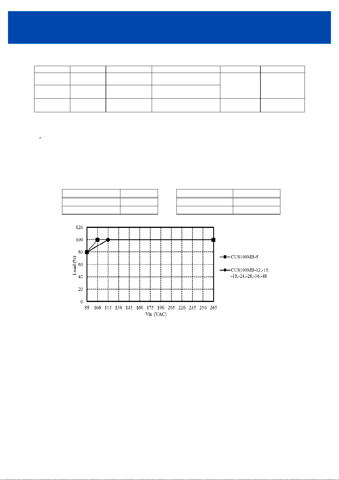
4-1. Input Voltage Range
Input voltage range is single phase 85-265VAC(47-63Hz). Never operate the unit out of the specified input voltage range to
avoid unit failure. For cases where conformance to various safeties required, input voltage range will be 100-240VAC (5060Hz). If input voltage is less than 115VAC, output power need to be derated.
Common B2P3-VH(LF)(SN) VAR-2 / VHR-3N
Common B4P-VH(LF)(SN) VHR-4N
Common ---
22~18AWG: STO-21T-250N
18~14AWG: STO-61T-250N
SVH-41T-P1.1
BVH-41T-P1.1
--- J.S.T.
J.S.T.
Derating curve of the Input voltage
CUS100MB-5 CUS100MB-12, -15 -18, -24, -28, -36, -48
Input Voltage (VAC) Load (%) Input Voltage (VAC) Load (%)
85 80 85 80
100~265 100 115~265 100
4-2. Output Voltage Range
Output voltage is set the rated value at shipment. V.ADJ trimmer (VR51) can adjust the output voltage within the range.
Output voltage range refers to the specification. To turn the trimmer clockwise, the output voltage will be increased. Take
note when the output voltage is increased excessively, over voltage protection (OVP) function may be triggered and voltage
will be shut down. Furthermore, when increasing the output voltage reduce the output current so as not to exceed the
maximum output power.
4-3. Inrush Current
These products equipped Power thermistor to limit the inrush Current. Higher inrush current will flow at higher ambient
temperature or re-input condition. Please select input switch and fuse carefully with the high temperature and re-input the
power condition. The Inrush Current value is under cold start at 25℃ in the specification.
<Page>
4/14
Page 5
TDK-Lambda
CUS100MB
INSTRUCTION MANUAL
4-4. Over Voltage Protection (OVP)
The OVP function (Inverter shut down method, manual reset type) is provided. Please refer to its specification for OVP
operating range. When OVP triggers, the output will be shut down. To reset OVP, remove the input of power supply for a few
minutes, and then re-input. In addition, the setting value of OVP is fixed and not adjustable. Pay attention not to apply higher
voltage externally to the output terminal to avoid unit failure. In case of inductive load, put protective diode in series to the
output power line.
4-5. Over Current Protection (OCP)
The OCP is hiccup mode with automatic recovery. The outputs will be automatically recovered when the overload condition
is canceled.
OCP function operates when the output current exceeds 105% of maximum DC output current of specification. Never operate
the unit under over current or shorted conditions for more than 30seconds, which may leads damage or insulation failure. OCP
setting is fixed and not to be adjusted externally.
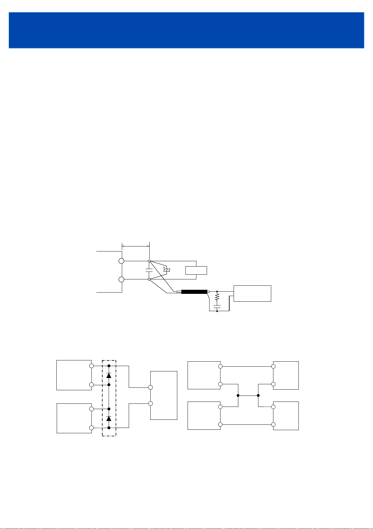
4-6. Output Ripple & Noise
The standard specification for maximum ripple value is measured according to measurement circuit specified as below. When
load lines are longer, ripple will becomes larger. In this case, electrolytic capacitor, film capacitor, etc. might be necessary to
use across the load terminal. The output ripple cannot be measured accurately if the probe ground lead of oscilloscope is too
long.
A circuit reducing light load input power consumption is built in this model. When output current is within 0-35% of rated
load, the internal switch element is intermittent operated, and the switching loss is decreased. The specification of the Ripple
& Noise changes by this intermittent operation. The dynamic load response characteristic changes by this intermittent
operation too. Different input voltage and dynamic load condition has different dynamic load response characteristic. Please
contact us for details.
150mm
+V
Power
Supply
-V
C1
4-7. Series Operation
For series operation, either method (A) or (B) is possible.
Method (A) Method (B)
+V
Power
Supply
-V
+V
Power
Supply
-V
(*1)
+
-
Load
C2
Coaxial Cable
1.5m 50Ω
Load
Power
Supply
Power
Supply
C1 : 0.1uF Cap., Film
C2 : 100uF Cap., Elect
C3 : 4700pF C ap., Ceramic
R1 : 50 Ω
R1
+V
-V
+V
-V
Oscilloscope
C3
Bandwidth : 20 MH z
+
Load
-
+
Load
-
(*1)Please select a bypass diode with maximum forward current rating more than output load current. And maximum reverse
voltage must withstand each power supply output voltage.
<Page>
5/14
Page 6

4-8. Parallel Operation
For parallel operation, method (B) is possible.
(A) To increase the Output Current is not possible.
Power
Supply
+V
-V
+
Load
-
TDK-Lambda
CUS100MB
INSTRUCTION MANUAL
(B) To use as Backup Power Supply.
1. Adjust the output voltage of each power supply to be
the same.
2. Set power supply output voltage higher by the
forward voltage drop (Vf) of diode.
Use within the specification for output voltage and
output power.
Power
Supply
+V
+V
Power
Supply
-V
-V
+V
Power
Supply
-V
+
Load
-
4-9. Isolation Test
Isolation resistance between Output and (Protective Earth) is more than 100MΩat 500VDC. For safety operation, voltage
setting of DC isolation tester must be done before the test. Ensure that the unit is fully discharged after the test.
Output - (Protective Earth) : 500VDC More than 100MΩ
.
AC(L)
AC(N)
+
‐
Isolation
Tester
4-10. Withstand Voltage
These products are designed to withstand 4.0kVAC between input and output, 2.0kVAC between input and , and 1.5kVAC
between output and each for 1 minute. When testing withstand voltage, set current limit of the withstand voltage test
equipment to 20mA. The applied voltage must be gradually increased from zero to the testing value and then gradually
decreased for shut down. When timer is used, the power supply may be damaged by high impulse voltage at timer switch on
and off. Connect input and output as follows.
Input - Output(Dashed line) : 4.0kVAC 1min(20mA)
Input - (Protective Earth)(Solid line) : 2.0kVAC 1min(20mA) Output - (Protective Earth) : 1.5kVAC 1min(20mA)
Withstand
Voltage Tester
Withstand
Voltage Tester
AC(L)
AC(N)
+
‐
<Page>
6/14
Withstand
Voltage Tester
AC(L)
AC(N)
+
‐
Page 7

TDK-Lambda
CUS100MB
INSTRUCTION MANUAL
Instructions for using the power supply in customer’s system
1. If the output of power supply is connected to FG in the application, the withstand voltage test between input and output (FG) should be tested
at 2kVAC.
2. If there is external noise filter and Y-caps connected at the input and output of the power supply, the voltage distribution between primary and
secondary circuit will be changed during the withstand voltage test, and may cause test fail. In this case, please contact TDK-Lambda for
the technical support and instructions.
5. Mounting
5-1. Mounting Directions
5-1-1. Mounting directions for models (except CUS100MB/A)
Recommended standard mounting direction is (A). Mounting direction (B)-(E) are also possible.
(A) Standard mounting (B) (C) (D) (E)
CN1(INPUT)
CN1
CN1
CN1
CN1
5-1-2. Mounting directions for CUS100MB/A
Recommended standard mounting direction is (A). Mounting direction (B)-(E) are also possible.
Please use the mounting holes on bottom side of the power supply, do not use the side of the chassis for power supply
mounting.
(A) Standard mounting (B) (C) (D) (E)
CN1
CN1
CN1
CN1
5-2. Output Derating
5-2-1. Output derating for CUS100MB and CUS100MB/B
Make sure that the specified temperature range is maintained.
(1) 5V model
Convection Cooling: Mounting A,B,C,D
& Force Air Cooling: Mounting A,B,C,D,E Convection Cooling: Mounting E
Ta (°C) Load (%) Ta (°C) Load (%)
-20 - +40 100 -20 - +35 100
50 90 45 90
60 75 55 75
70 50 65 50
<Page>
7/14
CN1
Page 8

(2) 12V, 15V, 18V model
Convection and Force Air Cooling
Mounting: A,B,C,D,E
Ta (°C) Load (%)
-20 - +50 100
70 50
TDK-Lambda
CUS100MB
INSTRUCTION MANUAL
(3) 24V Model
Convection Cooling Force Air Cooling
Mounting: A,B,C,D,E Mounting: A,B,C,D,E
Ta (°C) Load (%) Ta (°C) Load (%)
-20 - +40 100 -20 - +50 100
70 40 70 50
<Page>
8/14
Page 9

(4) 28V model
0
080
0
0
120
Convection Cooling
Mounting: A,B,C,D
Ta (°C) Load (% )
-20 - +40 100
50 80
70 40
Mounting: E
Ta (°C)
-20 - +35
5
70 40
Lo ad (%)
100
8
TDK-Lambda
CUS100MB
INSTRUCTION MANUAL
Force Air Cooling
Mounting: A,B,C,D,E
Ta (°C) Load (%)
-20 - +50 100
70 50
100
80
60
Load (%)
40
20
0
-20-10 0 1020304050607080
(5) 36V model
120
100
80
60
Load (%)
40
Convection Cooling
Mounting A,B,C,D
Convection Cooling
Mounting E
Force Air Cooling
Mounting A,B,C,D,E
Ta (°C)
Convection Cooling Force Air Cooling
Mounting: A,B,C,D,E Mounting: A,B,C,D,E
Ta (°C) Load (%) Ta (°C) Load (%)
-20 - +35 100
50 80 70 50
70 40
-20 - +50 100
Conve ction Cooling
Force Air Cooling
20
0
(6) 48V Model
120
100
80
60
Load (%)
40
20
0
-20-10 0 1020304050607080
Con vec t io n Cooling Force A ir Cooling
Mounting: A,B,C,D,E Mounting: A,B,C,D,E
Ta (°C) Load (%) Load (%)
-20 - +30 100 -20 - +50
5
70 40
Ta (°C)
Ta (°C)
70
Convection Cooling
Force Air Cooling
-20-10 0 1020304050607080
Ta (°C)
100
5
<Page>
9/14
Page 10

TDK-Lambda
CUS100MB
INSTRUCTION MANUAL
Condition of force air cooling
Recommend force air cooling with air velocity more than 1.2m/s (measured at component side of PCB) and air must flow
through component side, so that the maximum temperature of the surface of the following components will not exceed max
temperature in the table.
Components C5 T1
Max temperature
Absolute temperature = Temperature rise + Ambient temperature
95℃ 115℃
TEMPERATURE RISE TEST POINTS
5-2-2. Output derating fo r CUS100MB/A.
CUS100MB/A is convection cooling type. Make sure that the specified temperature range is maintained..
CUS100MB-5/A CUS100MB-12/A,15/A,18/A,24/A,28/A,36/A,48/A
Mounting A,B,C,D,E Mounting A,B,C,D,E
Ta (°C) Load (%)
-20 - +30 100
40 90
70 40
Ta (°C) Load (%)
-20 - +40 100
70 40
<Page>
10/14
Page 11

TDK-Lambda
CUS100MB
INSTRUCTION MANUAL
5-3. Mounting Method
5-3-1. Mounting method for standard model
Note: Except /A, /B and /G2 model.
All four mounting holes on this model should be utilized for best electrical and mechanical performance, with 8mm
(minimum height) metal standoffs.
Mounting Holes size
4 holesφ3.5mm.
Height more than 8mm spacer
Refer to the shadow in the figure below for allowable area touched by conductive material on top and bottom side of the PCB.
6
6
R
6
6
3
3
R
6
3
R
R
3
6
6
6
Condition to meet EMI, EMC, Isolation, Withstand Voltage and Cooling requirement.
Keep 4mm space minimum from the surface and sides of power supply, 8mm space minimum from the bottom side of PCB to meet safety
requirement, or more space depend on safety requirement. If the space is not enough, the specification of isolation and withstand voltage will
not be satisfied.
More space may be required in the surrounding of power supply and the upper area of components for effective cooling
depends on the application conditions.
terminal (Protective Earth) must be connected to the earth terminal of the equipment, also the two mounting holes (as
shown below) needed to be connected to earthed metal plane or metal chassis of end product by metal spacer to ensure EMC
and EMI performance.
All equipment ideally should be mounted inside an earthed shielded metal box. Alternatively an earthed metal plate can be
used to mount the power supply and load.
Earth Terminal
Wire
Terminal
Metal spacers
<Page>
11/14
Page 12

TDK-Lambda
CUS100MB
INSTRUCTION MANUAL
5-3-2. Mounting methodfor /B model
/B model is optional model with metal plate on the bottom.
The mounting holes on the metal plate are for power supply fixing. The M3 stud near the input connector is used to connect to
the protective earth.
Refer to the /B model outline drawings for the detailed dimensions.
(A)
GROUND
(B)
(A)
Mounting Holes
A: 3-φ3.5 holes for mounting screws to fix the power supply from top.
B: 3-M3 tapped, embossed and countersink holes for mounting screws to fix the power supply from bottom.
Ground: M3 stud for protective earth
(B)
(B)
(A)
Condition to meet EMI, EMC, Isolation, Withstand Voltage and Cooling.
Keep more than 4mm space from the top of components and the sides of PCB to meet safety requirement. If the space is not
enough, the specification of isolation and withstand voltage will not be satisfied.
More space may be required in the surrounding of power supply and the upper area of components for effective cooling
depends on the application conditions.
All equipment ideally should be mounted inside an earthed shielded metal box. Alternatively an earthed metal plate can be
used to mount the power supply and load to ensure the EMI and EMC performance.
5-3-3. Mounting methodfor /A model
/A model is optional model with metal chassis and cover.
The mounting holes on the bottom of the chassis are for power supply fixing. The M3 stud near the input connector can be
used to connect to the protective earth.
Refer to the /A model outline drawings for the detailed dimensions.
GROUND
(A)
(B)
(C)
(B)
VR51
CN51
1
2
3
4
CN1
2
1
(A)
(C)
(B)
(C)
(A)
Mounting Holes
A: 3-φ3.5 holes for mounting screws to fix the power supply from top.
B: 3-φ3.5 holes for mounting screws to fix the power supply from top.
C: 3-M3 tapped, embossed and countersink holes for mounting screws to fix the power supply from bottom.
Ground: M3 stud for protective earth
<Page>
12/14
Page 13

TDK-Lambda
CUS100MB
INSTRUCTION MANUAL
Condition to meet EMI, EMC, Isolation, Withstand Voltage and Cooling.
(1) This series is convection cooling type. In consideration of the heat radiation and safety, please keep a distance of more
than 15mm between the power supply and the peripheral parts. When lining up multiple units, please make sure to place
them 15mm or more apart from each other.
(2) Recommended torque for mounting screws of M3 screw : 0.49 N·m (5.0 kgf·cm).
(3) All equipment ideally should be mounted inside an earthed shielded metal box. Alternatively an earthed metal plate can be
used to mount the power supply and load to ensure the EMI and EMC performance.
5-3-4. Mounting methodfor /G2 model
/G2 model is optional model for installation in class II end equipment (without ground connection), such as used inside of a
plastic enclosure.
All four mounting holes on this model should be utilized for support the power supply
Keep enough space from the surrounding of the power supply for safety and cooling requirement, these products need to be fixed such that they
are isolated from unearthed accessible conductive parts by at least 2 MOPP’s for Class II installation.
6. EMC and Wiring Method
This power supply is primarily designed and manufactured to be used and enclosed in other equipment. The installation,
wiring, grounding and end application of the switching power supply in the equipment system may influence its EMC
characteristics. Therefore, the EMC performance has to be tested on end system level. Additional filtering may be required
depends on application and installation methods.
Please refer to following application notes which may help to improve EMC performance.
(1) The output load line and input line shall be separated each other and twisted individually to improve noise.
(2) Use all lines as thick and short as possible to made lower impedance.
(3) Noise can be reduced by attaching a capacitor to the load terminals.
(4) For safety and EMI considerations, connect (Protective Earth) terminal and Frame Ground terminal of equipment firmly.
7. External Fuse Rating
Refer to the following fuse rating when selecting the external fuses that are to be used on input line. Surge current flows when
line turns on. Have to use slow-blow or time-lag type fuse, not fast-blow fuse. Fuse rating is considered by in-rush current
value at line turn-on. Do not select the fuse according to input current (RMS.) values under the actual load condition
CUS100MB: 3.15A
8. Before concluding that the unit is at fault
(1) Check if the rated input voltage is connected.
(2) Check if the wiring of input and output is correct.
(3) Check if the wire thickness is enough.
(4) Check if the output current and output power does not over specification.
(5) Check if the output voltage adjust trimmer (V.ADJ) is properly adjusted. OVP might be triggered and output is shut down.
(6) Audible noise can be heard when input voltage waveform is not sinusoidal wave.
(7) Audible noise can be heard during Dynamic-Load operation.
(8) Ensure that a large capacitor is not connected across the output terminals. Please use within maximum capacitance shown
below.
Maximum external capacitance
MODEL 5V 12V 15V 18V 24V 28V 36V 48V
CUS100MB 10000uF 10000uF 5600uF 5600uF 4500uF 4000uF 4000uF 2000uF
<Page>
13/14
Page 14

TDK-Lambda
CUS100MB
INSTRUCTION MANUAL
9. Altitude
CUS100MB is safety approved for operation at below altitude.
- Up to 5000m by IEC60950-1 clearance requirement.
- Up to 5000m by IEC60601-1 clearance requirement.
Thermal evaluation should be considered for products operating at elevated altitudes above 2000m.
10. Warranty Condition
These products are under warranty for 3 years from the date of shipment. During the warranty period, TDK-Lambda will,
either repair or replace products prove to be defective.
3 years warranty applies but not limited to the following.
(1) Average operating temperature (ambient temperature of the power supply unit)is under 40℃.
(2) 3 years warranty base on 24 hours/day operation at 100% load.
Please refer to electrolytic capacitor life time from reliability data for various application conditions such as mounting, load
derating, operating ambient temperature etc.
Customer system design could be improved with better electrolytic capacitor life time by selecting proper application method.
Following cases are not covered by warranty.
(1) Improper usage like dropping products, applying shock and defects from operation exceeding specification of the units.
(2) Defects resulting from natural disaster (fire, flood etc.).
(3) Unauthorized modifications or repair.
<Page>
14/14
 Loading...