

Page 1
Page 1 of 20 17130 issue 31, June 2014
Alpha 600 Handbook
ENGLISH
General Safety Instructions:
READ SAFETY INSTRUCTIONS
Servicing:
These products are not customer serviceable. TDK-Lambda UK LTD. and their authorised agents only are permitted
to carry out repairs.
Critical Components:
These products are not authorised for use as critical components in nuclear control systems, life support systems or
equipment for use in hazardous environments without the express written approval of the Managing Director of TDKLambda EMEA.
Product Usage:
These products are designed for use within a host equipment which restricts access to authorised competent
personnel.
Environmental:
These products are IPX0, and therefore chemicals/solvents, cleaning agents and other liquids must not be used.
Environment:
This power supply is a switch mode power supply for use in applications within a Pollution Degree 2, overvoltage
category II environment. Material Group IIIb PCB’s are used within it.
Output Loading:
The output power taken from the power supply must not exceed the rating stated on the power supply label, except
as stated in the product limitations in this handbook.
Input Parameters:
This product must be operated within the input parameters stated in the product limitations in this handbook.
End of Life Disposal:
The unit contains components that require special disposal. Make sure that the unit is properly disposed of at the
end of its service life and in accordance with local regulations.
RISK OF ELECTRIC SHOCK
High Voltage Warning:
Dangerous voltages are present within the power supply. The professional installer must protect service personnel
from inadvertent contact with these dangerous voltages in the end equipment.
This product must be reliably earthed and professionally installed in accordance with the prevailing local electrical
wiring regulations and safety standards.
The (+) or (-) output(s) can be earthed or left floating.
The unit cover(s)/chassis must not be made user accessible.
Approval Limitations: Use in North America (AC units only)
When this product is used on 180-250 VAC mains with no neutral, connect the two live wires to L (live) and N
(neutral) terminals on the input connector. In this instance double pole fusing is required.
The mains input connector is not acceptable for use as field wiring terminals.
Page 2
Page 2 of 20 17130 issue 31, June 2014
Alpha 600 Handbook
Do not use mounting screws, which penetrate the unit more than 4.5mm.
Special earthing screws are used on these products which connect the cover to the chassis. They must not be
removed. If they are removed by mistake, they must be replaced with new ones and the product tested for earth
bonding.
An internal fuse protects the unit and must not be replaced by the user. In case of internal defect, the unit must be
returned to TDK-Lambda UK LTD or one of their authorised agents.
WARNING: These products are Class 1 and must therefore be reliably earthed and professionally installed in
accordance with the prevailing electrical wiring regulations and the safety standards covered herein.
A suitable mechanical, electrical and fire enclosure must be provided by the end use equipment for mechanical,
electric shock and fire hazard protection.
Energy Hazards:
Certain modules are capable of providing hazardous energy (240VA) according to output voltage setting. Final
equipment manufactur ers must provide protec t ion to s ervice per s onn el aga inst i nad verte nt con tac t with the s e
module output terminals. If set such that hazardous energy can occur then the module terminals or connections must
not be user accessible.
HOT SURFACE
External Hot Surfaces:
In accordance with local regulations for Health and Safety at work, manufacturers have an obligation to protect
service engineers as well as users. In order to comply with this, a label must be fitted to these products which is
clearly visible to service personnel accessing the overall equipment, and which legibly warns that surfaces of these
products may be hot and must not be touched when the products are in operation.
The ventilation openings on these products must not be impeded. Ensure that there is at least 50mm spacing
between any obstruction and the ventilation openings.
The unit cover/chassis is designed to protect skilled personnel from hazards. They must not be used as part of the
external covers of any equipment where they may be accessible to operators, since under full load conditions, part or
parts of the unit chassis may reach temperatures in excess of those considered safe for operator access.
Page 3
Page 3 of 20 17130 issue 31, June 2014
Alpha 600 Handbook
DEUTSCH
Allgemeine Sicherheitsvorschriften:
LESEN SIE DIE SICHER H EITSVORSCHRIFTEN
Wartung:
Diese Produkte können nicht durch den Kunden gewartet werden. Nur TDK-Lambda UK LTD. und deren
zugelassene Vertriebshä nd ler sind zur Durchf ühr un g v on Reparaturen berechtigt.
Kritische Komponenten:
Diese Produkte sind nicht für die Verwendung als kritische Komponenten in nuklearen Kontrollsystemen,
Lebenserhaltungssystemen oder Geräten in gefährlichen Umgebungen geeignet, sofern dies nicht ausdrücklich und
in Schriftform durch den Geschäftsführer von TDK-Lambda EMEA genehmigt wurde.
Produktverwendung:
Diese Produkte sind zur Verwendung inn er ha lb von Ho st -Anlagen gedacht, die einen auf das Fachpersonal
beschränkten Zugang haben.
Umwelt:
Diese Produkte sind IPX0, aus diesem Grund dürfen keine Chemikalien/Lösungsmittel, Reinigungsmittel und andere
Flüssigkeiten verwendet werden.
Umgebung:
Dieses Netzteil ist ein Schaltnetzteil zur Verwendung in einer Umgebung mit einem Verschmutzungsgrad 2,
Überspannungskategor ie II . Mater ialgr u ppe IIIb m it dar in ver wende ten PC Bs .
Ausgangsstrom:
Der Ausgangsstrom des Netzteiles darf die Leistung, die auf dem Label des Netzteiles vermerkt ist, nur dann
überschreiten, wenn dies in den Produktgrenzen dieses Handbuches ausgezeichnet ist.
Eingangsparameter:
Dieses Produkt muss innerhalb der Eingangsparameter, die in den Produktgrenzen dieses Handbuches angegeben
sind, betrieben werden.
Entsorgung am Ende der Betriebszeit:
Das Gerät enthält Komponenten die unter Sondermüll fallen. Das Gerät muss am Ende der Betriebszeit
ordnungsgemäß und in Übereinstimmung mit den regionalen Bestimmungen entsorgt werden.
GEFAHR DURCH ELEKTRISCHEN SCHLAG
Hochspannungswarnung:
Innerhalb des Netzteiles gibt es gefährliche Spannungen. Der Elektroinstallateur muss das Wartungspersonal vor
versehentlichem Kontakt mit den gefährlichen Spannungen im Endgerät schützen.
Dies Produkt muss sicher geerdet und von qualifiziertem Personal in Übereinstimmung mit den gültigen regionalen
Bestimmungen zu Verdrahtungen sowie den Sicherheitss tandar ds ins ta llier t wer d en.
Die (+) oder (-) Ausgänge können geerdet werden oder unangeschlossen bleiben.
Die Abdeckung des Gerätes/das Gehäuse darf für den Benutzer nicht zugänglich sein.
Genehmigungsgrenzen: Verwendung in Nordamerika (nur AC-Geräte)
Wenn dieses Produkt an eine 180-250 VAC Hauptleitung ohne Nullleiter angeschlossen wird, müssen die beiden
stromführenden Leitungen an die Anschlüsse L (stromführend) und N (Nullleiter) in der Eingangsverbindung
angeschlossen werden. In diesem Fall ist eine zweipolige Sicherung erforderlich.
Der Haupteingangsanschluss ist nicht für die Verwendung als Feldverdrahtungsanschluss geeignet.
Page 4
Page 4 of 20 17130 issue 31, June 2014
Alpha 600 Handbook
Verwenden Sie keine Befestigungsschrauben, die mehr als 4.5mm in das Gerät eindringen.
Zur Befestigung der Abdeckung am Gehäuse werden für diese Produkte spezielle Erd ungs sc hr aub en ver we ndet .
Diese dürfen nicht entfernt werden. Sollten sie versehentlich entfernt werden, müssen sie durch neue ersetzt und
das Produkt auf Erdschluss geprüft werden.
Eine interne Sicherung schützt das Gerät und darf durch den Benutzer nicht ausgetauscht wer de n. Im Fall von
internen Defekten muss das Gerät an TDK-Lambda UK LTD oder einen der autorisierten Vertriebshändler
zurückgeschickt werden.
WARNUNG: Diese Produkte sind Produkte der Klasse 1 und müssen daher sicher geerdet und von qualifiziertem
Personal in Übereinstimmung mit den gültigen regionalen Bestimmungen zu Verdrahtungen sowie den
Sicherheitsstandards installiert werden.
Ein geeignetes mechanisches, elektrisches und brandgeschütztes Gehäuse muss als Schutz vor der Gefahr von
mechanischen Risiken, Stromschlägen und Brands c h ut z in dem Endgerät vorgesehen werden.
Gefahren durch elektrische Energie:
Von bestimmten Modulen kann je nach Einstellung der Ausgangsspannung gefährliche elektrische Energie
ausgehen (240 VA). Die Endgerätehersteller müssen einen Schutz für Servicepersonal vor unbeabsichtigtem
Kontakt mit den Ausgangsanschlüssen dieser Module vorsehen. Kann aufgrund der Einstellung gefährliche
elektrische Energie auftreten, dürfen die Modulanschlüsse für den Benutzer nicht zugänglich sein.
HEISSE OBERFLÄCHEN
Äußere heiße Oberflächen:
In Übereinstimmung mit den regionalen Bestimmungen für Gesundheit und Sicherheit bei der Arbeit ist der Hersteller
für den Schutz von Wartungspersonal und Benutzern verantwortlich. Um diesen Bes tim mungen gerecht zu werden,
muss auf den Produkten ein Label angebracht werden, das deutlich sichtbar für das Wartungspersonal mit Zugriff
auf die gesamte Anlage ist, und das gut lesbar auf die eventuell heiße Oberfläche des Gerätes hinweist und das
Berühren des Produktes in Betrieb untersagt.
Die Belüftungsöffnungen an diesem Produkt dürfen nicht blockiert werden. Achten Sie darauf, dass mindestens
50 mm Abstand zwischen Hindernissen und den Belüftungsöffnungen bleibt.
Die Geräteabdeckung/das Gehäuse ist so entworfen, dass das Fachpersonal vor Gefahren geschützt wird. Sie
dürfen nicht als Teil der externen Abdeckung für Geräte verwendet werden, die für den Betreiber zugänglich sein
müssen, da Teile oder das gesamte Gerätegehäuse unter voller Auslastung übermäßige Temperaturen erreichen
kann, die für den Zugang des Betreibers nicht mehr als sicher betrachtet werden.
Page 5
Page 5 of 20 17130 issue 31, June 2014
Alpha 600 Handbook
FRANÇAIS
Consignes générales de sécurité:
LIRE LES CONSIGNES DE SECURITE
Entretien:
Ces produits ne peuvent pas être réparés par l’utilisateur. Seuls, TDK-Lambda UK LTD et ses agents agréés sont
autorisés à effectuer des réparations.
Composants critiques:
Ces produits ne doivent pas être utilisés en tant que composants critiques dans des systèmes de commande
nucléaire, dans des systèmes de sauvetage ou dans des équipements utilisés dans des environnements dangereux,
sans l'autorisation écrite expresse du directeur général de TDK-Lambda EMEA.
Utilisation du produit:
Ces produits sont conçus pour être utilisés dans un équipement hôte dont l'accès n'est autorisé qu'aux personnes
compétentes.
Environnement:
Ces produits sont IPX0, et donc on ne doit pas utiliser des produits chimiques/solvants, des produits de nettoyage et
d'autres liquides.
Environnement fonctionnel :
Cette alimentation fonctionne en mode commutation pour utilisation dans des applications fonctionnant dans un
environnement avec Degré de Pollution 2 et catégorie de surtension II. Elle utilise des cartes des circuits imprimés
(PCB) de Groupe IIIb.
Intensité soutirée:
L'intensité soutirée de l'alimentation ne doit pas dépasser l'intensité nominale marquée sur la plaque signalétique,
sauf indications contraires dans les limitations du produit décrit dans ce manuel.
Paramètres d'entrée:
Ce produit doit être utilisé à l'intérieur des paramètres d'entrée indiqués dans les limitations du produit dans ce
manuel.
Elimination en fin de vie:
L'alimentation contient des composants nécessitant des dispositions spéciales pour leur élimination. Vérifiez que
cette alimentation est mise au rebut correctement en fin de vie utile et conformément aux réglementations locales en
vigueur.
RISQUE DE CHOC ELECTRIQUE
Attention-Danger haute tension:
Des tensions dangereuses sont présentes dans l'alimentation. L'installateur doit protéger le personnel d'entretien
contre un contact involontaire avec ces tensions dangereuses dans l'équipement final.
Ce produit doit être raccordé à une terre fiable et installé par des professionnels en respectant les réglementations
locales de câblages électriques en vigueur et les normes de sécurité.
Les sorties (+) ou (-) peuvent être raccordées à la terre ou laissées flotttantes.
Le couvercle/châssis de l'alimentation ne doit pas être accessible à l'utilisateur.
Limitations approuvées : Utilisation en Amérique du Nord (alimentations AC seulement)
Si ce produit est utilisé sur une alimentation pri ncip ale 180-250 VAC sans neutre, raccordez les deux fils de phase
aux bornes L (phase) et N (neutre) sur le connecteur d'entrée. Dans ce cas, un fusible bipolaire est nécessaire.
Page 6
Page 6 of 20 17130 issue 31, June 2014
Alpha 600 Handbook
Le connecteur d'entrée d'alimentation principale ne doit pas être utilisé comme borne de raccordement.
N'utilisez pas de vis pénétrant dans le module sur une profondeur supérieure à 4.5 mm.
Des vis de terre spéciales sont utilisées sur ces produits pour raccorder le couvercle au châssis. Elles ne doivent
pas être enlevées. Si elles sont enlevées par erreur, elles doivent être remplacées et le produit doit être testé pour
vérifier que le raccordement à la terre est correct.
Un fusible interne protège le module et ne doit pas être remplacé par l'utilisateur. En cas de défaut interne, le module
doit être renvoyé à TDK-Lambda UK LTD ou l'un de ses agents agréés.
AVERTISSEMENT: Ces produits sont des produits Classe 1 et donc doivent être raccordés à une terre fiable et
installés par un professionnel en respectant les réglementations de câblage électrique en vigueur et les normes de
sécurité indiquées ici.
Une enceinte appropriée doit être prévue par l'utilisateur final pour assurer la protection contre les chocs
mécaniques, les chocs électriques et l'incendie.
Energies dangereuses :
Certains modules peuvent générer une énergie dangereuse (240 VA) selon le réglage de tension de sortie. Le
fabricant de l'équipement final doit assurer la protection des techniciens d'entretien contre un contact involontaire
avec les bornes de sortie de ces modules. Si une telle tension dangereuse risque de se produire, les bornes ou les
connexions du module ne doivent pas être accessibles par l'utilisateur.
SURFACE CHAUDE
Surfaces chaudes extérieures:
Conformément aux réglementations locales concernant la santé et la sécurité sur les lieux de travail, les fabricants
doivent protéger les techniciens d'entretien et les utilisateurs. Pour cela, une plaque signalétique doit être installée
sur ces produits, et cette plaque doit être bien visible pour les techniciens d'entretien intervenant sur l'équipement, et
elle doit indiquer de manière bien visible que les surfaces de ces produits peuvent être chaudes et qu'elles ne
doivent pas être touchées lorsque les produits fonctionnent.
Les orifices de ventilation sur ces produits ne doivent pas être obstrués. Vérifiez qu'il y a un espace libre d'au moins
50 mm entre une obstruction et les orifices de ventilation.
Le couvercle et le châssis du module sont conçus pour protéger des personnels expérimentés. Ils ne doivent pas
être utilisés comme couvercles extérieurs d'un équipement, accessible aux opérateurs car en condition de puissance
maximum, des parties du châssis peuvent atteindre des températures considérées comme dangereuses pour
l'opérateur.
Page 7

Page 7 of 20 17130 issue 31, June 2014
Alpha 600 Handbook
ITALIANO
Norme generali di sicurezza:
SI PREGA DI LEGGERE LE NORME DI SICUREZZA
Manutenzione:
Il cliente non può eseguire alcuna manutenzione su questi prodotti. L'esecuzione delle eventuali riparazioni è
consentita solo a TDK-Lambda UK LTD e ai suoi agenti autorizzati.
Componenti critici:
Non si autorizza l'uso di questi prodotti come componenti critici all'interno di sistemi di controllo nucleari, sistemi
necessari alla sopravvivenza o apparecchiature destinate all'impiego in ambienti pericolosi, senza l'esplicita
approvazione scritta dell'Amministratore Delegato di TDK-Lambda EMEA.
Uso dei prodotti:
Questi prodotti sono progettati per l'uso all'interno di un'apparecchiatura ospite che limiti l'accesso al solo personale
competente e autorizzato.
Condizioni ambientali:
Questi prodotti sono classificati come IPX0, dunque non devono essere utilizzati sostanze chimiche/solventi, prodotti
per la pulizia o liquidi di altra natura.
Ambiente:
Questo prodotto è un alimentatore a commutazione, destinato all'uso in applicazioni rientranti in ambienti con le
seguenti caratteristiche: Livello inquinamento 2, Categoria sovratensione II. Questo prodotto contiene schede di
circuiti stampati in materiali di Gruppo IIIb.
Carico in uscita:
La potenza in uscita ottenuta dall'alimentatore non deve superare la potenza nominale indicata sulla targhetta
dell'alimentatore, fatto salvo dove indicato nei limiti per i prodotto specificati in questo manuale.
Parametri di alimentazione:
Questo prodotto deve essere utilizzato entro i parametri di alimentazione indicati nei limiti per il prodotto, specificati
in questo manuale.
Smaltimento:
L'unità contiene componenti che richiedono procedure speciali di smaltimento. Accertarsi che l'unità venga smaltita
in modo corretto al termine della vita utile e nel rispetto delle normative locali.
RISCHIO DI SCOSSA ELETTRICA
Avvertimento di alta tensione:
All'interno dell'alimentatore sono presenti tensioni pericolose. Gli installatori professionali devono proteggere il
personale di manutenzione dal rischio di contatto accidentale con queste tensioni pericolose all'interno
dell'apparecchiatura finale.
Questo prodotto deve essere messo a terra in modo affidabile e installato in modo professionale, nel rispetto delle
norme di sicurezza e dei regolamenti vigenti in ambito locale in materia di collegamenti elettrici.
Le uscite (+) o (-) possono essere messa a terra o lasciate isolate.
I coperchi/il telaio dell'unità non devono essere accessibili da parte dell'utente.
Page 8
Page 8 of 20 17130 issue 31, June 2014
Alpha 600 Handbook
Limiti di approvazione: Uso in America Settentrionale (solo per le unità a CA)
Se il prodotto è utilizzato su reti a 180 - 250 VCA senza neutro, collegare i due fili sotto tensione ai terminali L (sotto
tensione) e N (neutro) sul connettore di alimentazione. In tal caso è necessaria protezione con un fusibile bipolare.
Il connettore dell'alimentazione principale non può essere utilizzato come terminale di collegamento di campo.
Non utilizzare viti che penetrano nell'unità per più di 4.5 mm.
Per questi prodotti vengono usate viti speciali di messa a terra, che collegano il coperchio al telaio. Tali viti non
devono essere rimosse. Se le viti vengono tolte per errore, vanno sostituite con nuove viti ed occorre testare il
prodotto per verificarne il collegamento a massa.
Un fusibile interno protegge l'unità e non de ve essere s os titu ito da ll'ut ent e. Nel l'e v entu al ità di un difetto int er n o,
restituire l'unità a TDK-Lambda UK LTD o a uno dei suoi agenti autorizzati.
AVERTIMENTO: Questi prodotti sono di Classe 1 e come tali devono essere messi a terra in modo affidabile e
installati in modo professionale, nel rispetto dei regolamenti vigenti in ambito locale in materia di collegamenti elettrici
e nelle norme di sicurezza in essi contemplati.
L'apparecchiatura finale deve includere una recinzione meccanica, elettrica e antincendio per proteggere dai pericoli
di natura meccanica, dalle scosse elettriche e dai pericoli di incendio.
Pericoli energetici:
Alcuni moduli sono in grado di erogare energia pericolosa (240 VA) a seconda della tensione in uscita impostata. I
produttori delle apparecchiature finali sono tenuti a proteggere il personale di manutenzione dal rischio di contatto
accidentale con questi terminali dei moduli di uscita. Se impostati su livelli che non escludono l'erogazione di energia
pericolosa, questi terminali o collegamenti non devono risultare accessibili da parte dell'utente.
SUPERFICIE CALDA
Superfici esterne calde:
Coerentemente con le norme locali in materia di salute & sicurezza professionali, i produttori sono tenuti a
salvaguardare i tecnici di manutenzione, e inoltre gli utenti. Per far fronte a tali obblighi, i prodotti devono presentare
una targhetta, chiaramente visibile al personale di manutenzione che accede all'apparecchiatura nel complesso e
che risulti inoltre leggibile e avverta gli addetti del rischio che le superfici di questi prodotti possono scottare e non
vanno toccate con i prodotti in funzione.
Le griglie di ventilazione su questi prodotti non devono essere ostruite. Verificare che vi sia una distanza minima di
50 mm fra le griglie di ventilazione e qualsiasi eventuale ostruzione.
Il coperchio/telaio dell'unità è realizzato per proteggere il personale esperto dai pericoli. Non deve essere usato
come parte degli involucri esterni di qualsiasi apparecchiatura, se risulta accessibile da parte degli addetti, poiché è
possibile che in condizioni di pieno carico una o più parti del telaio dell'unità giunga/giungano a temperature superiori
ai limiti considerati sicuri per l'accesso da parte degli addetti.
Page 9

Page 9 of 20 17130 issue 31, June 2014
Alpha 600 Handbook
ESPAÑOL
Instrucciones generales de seguridad:
LEA LAS INSTRUCCIONES DE SEGURIDAD
Servicio:
Estos productos no pueden ser reparados por los clientes. TDK-Lambda UK LTD. y sus agentes autorizados son
los únicos que pueden llevar a cabo las reparaciones.
Componentes fundamentales:
Estos productos no pueden ser utilizados como componentes fundamentales en sistemas de control nuclear,
sistemas de soporte vital o equipos a utilizar en entornos peligrosos sin el consentimiento expreso por escrito del
Director General de TDK-Lambda EMEA.
Uso de los productos:
Estos productos han sido diseñados para ser utilizados en un equipo central que restrinja el acceso al personal
cualificado autorizado.
Medioambiental:
Estos productos son IPX0 y, por tanto, no pueden utilizarse sustancias químicas/disolventes, agentes de limpieza ni
otros líquidos.
Medio ambiente:
Esta fuente de alimentación es una fuente de alimentación de modo conmutado a utilizar en aplicaciones dentro de
un entorno con un Grado de contaminación 2 y una Categoría de sobretensión II. En él se utilizan policloruros de
bifenilo del Grupo de materiales IIIb.
Carga de salida:
La potencia de salida tomada de la fuente de alimentación no puede sobrepasar el valor nominal indicado en la
etiqueta de la fuente de alimentación, excepto en los casos indicados en las limitaciones del producto en este
manual.
Parámetros de entrada:
Este producto debe ser utilizado dentro de los parámetros de entrada indicados en las limitaciones del producto en
este manual.
Desecho de la unidad:
La unidad contiene componentes que deben ser desechados de una manera especial. Asegúrese de desechar
correctamente la unidad al final de su vida útil y conforme a las normas locales vigentes.
PELIGRO DE DESCARGAS ELÉCTRICAS
Advertencia de alta tensión:
En esta fuente de alimentación hay tensiones peligrosas. El instalador profesional debe proteger al personal de
servicio contra cualquier contacto accidental con estas tensiones peligrosas en el equipo final.
Este producto se puede conectar de forma fiable a tierra e instalar profesionalmente de conformidad con las
regulaciones locales para los cableados eléctricos y las normas de seguridad vigentes.
La salida o salidas (+) o (-) pueden conectarse a tierra o se las puede dejar flotando.
Debe impedirse el acceso de los usuarios a la cubierta o cubiertas y al chasis de la unidad.
Page 10

Page 10 of 20 17130 i ssue 31, June 2014
Alpha 600 Handbook
Limitaciones a las aprobaciones: de uso sólo en EE. UU. (sólo unidades de CA)
Cuando este producto se utilice en una red de 180-250 V CA sin un punto neutro, conecte los dos cables activos a
los bornes L (activo) y N (neutro) del conector de entrada. En este caso se necesita una protección por fusibles
bipolar.
El conector de entrada de la red no es apto para ser utilizado a modo de bornes de cableado de campo.
No utilice tornillos de montaje susceptibles de penetrar en la unidad más de 4.5 mm.
Con estos productos se utilizan unos tornillos de puesta a tierra especiales que conectan la cubierta al chasis. No se
deben quitar en ningún caso. En caso de quitarlos por error, hay que reemplazarlos por unos nuevos y comprobar la
conexión a tierra del producto.
Un fusible interno protege la unidad y este no debe ser nunca reemplazado por el usuario. En caso de existir algún
defecto interno, la unidad debe ser enviada a TDK-Lambda UK LTD o a uno de sus agentes autorizados.
AVISO: Estos productos son de Clase 1 y, por tanto, se deben conectar de forma fiable a tierra y sólo pueden ser
instalados por profesionales de acuerdo con con las regulaciones sobre cableados eléctricos y las normas de
seguridad vigentes cubiertas en este documento.
El equipo de uso final debe constituir un recinto de protección mecánica, eléctrica y contra incendios de protección
mecánica, contra descargas eléctricas y contra el peligro de incendios.
Peligros de energía:
Algunos módulos pueden generar energía peligrosa (240VA) dependiendo de la configuración de la tensión de
salida. Los fabricantes de equipos finales deben proteger al personal de servicio contra un contacto accidental con
estos bornes de salida de los módulos. Si se configura de modo que pueda generarse energía peligrosa, hay que
evitar que el usuario pueda acceder a los bornes o conexiones del módulo.
SUPERFICIE CALIENTE
Superficies externas calient es:
Según las normas locales relativas a la Salud y Seguridad en el trabajo, los fabricantes están obligados a proteger a
los ingenieros de servicio además de a los usuarios. Para que esto se cumpla, debe colocarse una etiqueta en estos
productos que pueda ser vista claramente por el personal de servicio que accede al equipo general, y con
advertencias legibles de que las superficies de estos productos pueden estar calientes y no deben tocarse cuando
los productos se encuentran en funcionamiento.
Las aberturas de ventilación de estos productos no deben obstruirse jamás. Asegúrese de que quede una
separación de 50 mm por lo menos entre cualquier obstrucción y las aberturas de ventilación.
La cubierta/chasis de la unidad ha sido diseñada para que proteja a las personas cualificadas de los peligros. No
deben ser utilizadas como parte de las cubiertas externas de cualquier equipo al que pueden acceder los operarios,
ya que bajo unas condiciones de carga completa, la pieza o piezas del chasis de la unidad pueden alcanzar
temperaturas superiores a las consideradas seguras para el acceso de los operarios.
Page 11
Page 11 of 20 17130 i ssue 31, June 2014
Alpha 600 Handbook
PORTUGUÊS
Instruções gerais de segurança:
LEIA AS INSTRUÇÕES DE SEGURANÇA
Manutenção:
Estes produtos não são podem ser submetidos a manutenção por parte do cliente. Apenas a TDK-Lambda UK LTD
e os seus agentes autorizados têm permissão para realizar reparações.
Componentes essenciais:
Não é autorizada a utilização destes produtos como componentes essenciais de sistemas de controlo nuclear,
sistemas de suporte de vida ou equipamento para utilização em ambientes perigosos sem a expressa autorização
por escrito do Director-Geral da TDK-Lambda EMEA.
Utilização do produto:
Estes produtos foram concebidos para utilização dentro de um equipamento de alojamento que apenas permita o
acesso a pessoal qualificado autorizado.
Ambiental:
Estes produtos são IPX0 e, como tal, não se devem utilizar químicos/solventes, agentes de limpeza e outros
líquidos.
Ambiente:
Esta fonte de alimentação é uma fonte de alimentação do modo de comutação para utilização em aplicações com
um Nível de Poluição 2 e ambientes da categoria de sobretensão II. São utilizadas placas de circuitos impressos do
grupo de materiais IIIb.
Carga de saída:
A potência de saída extraída da fonte de alimentação não deve exceder a classificação assinalada na etiqueta da
fonte de alimentação, excepto quando indicado nas limitações do produto neste guia.
Parâmetros de entrada:
Este produto deve ser utilizado dentro dos parâmetros de entrada indicados nas limitações do produto neste guia.
Eliminação no fim de vida:
A unidade contém componentes que necessitam de procedimentos especiais de eliminação. Certifique-se de que a
unidade é devidamente eliminada no fim da sua vida útil e que tal é feito em conformidade com os regulamentos
locais.
RISCO DE CHOQUE ELÉCTRICO
Aviso de alta tensão:
Estão presentes tensões perigosas dentro da fonte de alimentação. O profissional que realizar a instalação deve
proteger o pessoal de assistência contra contactos inadvertidos com estas tensões perigosas do equipamento final.
Este produto deve ser ligado à terra de forma fiável e instalado por um profissional, de acordo com as normas de
segurança e os regulamentos locais vigentes em relação a cablagens eléctricas.
As saídas (+) e (-) podem ser ligadas à terra ou deixadas soltas.
O chassis/cobertura(s) da unidade não deve estar acessível ao utilizador.
Page 12

Page 12 of 20 17130 i ssue 31, June 2014
Alpha 600 Handbook
Limitações da aprovação: Utilização na América do Norte (apenas unidades de corrente alternada)
Quando este produto é utilizado em fontes de alimentação 180-250 VAC sem ligação neutra, ligue os dois cabos
sob tensão aos terminais L (tensão) e N (neutro) do conector de entrada. Neste caso é necessário uma ligação de
fusíveis de dois pólos.
O conector de entrada de alimentação não deve ser utilizado como terminal de cablagens no local.
Não utilize parafusos de montagem, uma vez que estes penetrarão na unidade em mais do que 4.5 mm.
Nestes produtos utilizam-se parafusos especiais de ligação à terra, que ligam a cobertura ao chassis. Não devem
ser removidos. Se forem removidos por engano, deverão ser substituídos por parafusos novos, devendo-se testar a
ligação à terra do produto.
Existe um fusível interno que protege a unidade e que não deve ser substituído pelo utilizador. Em caso de defeito
interno, a unidade deve ser devolvida à TDK-Lambda UK LTD ou a um dos seus agentes autorizados.
AVISO: Estes produtos pertencem à Classe 1, devendo assim ser ligados à terra de forma fiável e instalado por
profissionais, de acordo com os regulamentos locais vigentes em relação a cablagens eléctricas e as normas de
segurança aqui mencionadas.
O equipamento de utilização final deve fornecer um bastidor com protecção mecânica, eléctrica e contra incêndios
adequada.
Perigos de energia:
Alguns módulos tem a capacidade de fornecer energia perigosa (240 VA), de acordo com a configuração da tensão
de saída. O equipamento final do fabricante deve garantir que o pessoal de assistência está protegido contra
contactos inadvertidos com estes terminais de saída do módulo. Se essa energia perigosa for produzida, as
ligações e os terminais do módulo não devem ser acessíveis pelos utilizadores.
SUPERFÍCIE QUENTE
Superfícies quentes externas:
Segundo com os regulamentos locais sobre saúde e segurança no local de trabalho, os fabricantes têm a obrigação
de proteger os técnicos de manutenção, bem como os utilizadores. De forma a respeitar este regulamento, estes
produtos deverão ter uma etiqueta que seja facilmente visível ao pessoal de assistência que aceda ao equipamento
em geral, e que alerte, de forma legível, para o facto de as superfícies destes produtos poderem estar quentes, não
devendo ser tocadas quando os produtos estão em funcionamento.
As aberturas de ventilação destes produtos não devem ser obstruídas. Certifique-se de que existe um espaçamento
de pelo menos 50 mm entre qualquer obstrução e as aberturas de ventilação.
O chassis/cobertura da unidade está concebido de forma a proteger o pessoal especializado de perigos. Não devem
ser utilizados como parte das coberturas externas de qualquer equipamento em que possam estar acessíveis aos
operadores, uma vez que em condições de carga máxima, algumas peças do chassis da unidade podem atingir
temperaturas superiores às consideradas seguras para o acesso do operador.
Page 13

Page 13 of 20 17130 i ssue 31, June 2014
Alpha 600 Handbook
Environmental Specifications:
Description
Operation
Storage
Use
Indoor
-
Temperature
0 to 50°C (derating 2.5%°C above 50°C to 65°C -
Not covered by approvals).
-40°C to +85°C
Humidity 5 to 95% RH non-condensing.
5% to 95% RH non-
condensing
Altitude
-200m to 3000m
-200m to 5000m.
Pressure
70kPa to 106kPa
54kpa to 106kpa
Orientation
Horizontal, on either side or vertical with
airflow upwards.
All
Material Group
IIIb
Pollution Degree
2
Overvoltage Categor y
II
Class
I
Weight
2.4 Kg (Dependent on configuration)
IP Rating
IPX0
Level of Insulation:
Dielectric Strength testing is carried out as follows:
Primary mains circuit to earth - 2.25 - 2.35kVDC
Primary mains circuits to transformer core - 4.25 - 4.35kVDC*
Primary mains circuits to secondary -4.25 - 4.35kVDC*
Outputs to each other and to earth are isolated to 500VDC
*This test is not possible with modules fi tted to the unit as damage to RFI capacitors will occur).
Safety Approvals:
UL60950-1 and CSA22.2 No 60950-1-UL recognised.C-UL for Canada.
IEC/EN60950-1 - CE mark. CE marking when applied to any Alpha 600 product, indicates compliance with the Low
Voltage Dircetive (2006/95/EC) in that it complies with EN60950-1, and with Directive 2011/65/EU of the European
Parliament and of the Council of 8 June 2011 on the restriction of the use of certain hazardous substances in
electrical and electronic equipment.
Fusing: Internal fuse (FS101) 6.3 x 32mm, F12AH/250V
Symbols:
AC DC EARTH N – Neutral L – Live
PRODUCTS COVERED
Unit Configuration Code:
Alpha 600, Alpha 600W and CA600 are identical.
(may be prefixed by NS - # / or - where # may be up to any four letters and may be followed by - $; where $
may be any number between 000 to 999, indicating non-safety related model differences.)
Alpha 600 or CA600 may be followed by: TL, RL, LL, ML, A or no letter,
where TL = Tiny leakage input filter
RL = Reduced leakage input filter
LL = Low leakage input filter
ML = Medium leakage input filter
A = Class A input filter
No letter = Class B input filter
Page 14

Page 14 of 20 17130 i ssue 31, June 2014
Alpha 600 Handbook
may be followed by: LSF, RA or QF
Where LSF = Low speed fan
RA = Reverse air fan
QF = Quiet fan
followed by up to five of the following:
@ followed by AA, A, AL, BB, B, CC, C, CL, CM, CH, DD, D, FF, F, GG, G, JJ, J, KK, K, LL, L, MM, M, NN, N, QQ, Q, RR, R, SS,
S, TT, T, UU, U, WW, W, ZZ or Z.
optionally followed by _MF, MFE, MFU, MFV, _PA, _IN, _PP, MJ, RJ, PJ, IJ, _RP, RPA, RPB, RPC, RPD or _MG
or B/S
or @/@ followed by: E,EB, EQ, EL, EH, H, P or PL:
where @ and @/@ = applicable voltage range and the following one or two letters are the module type.
_MF, MFE = Mains fail option (may also be called X).
MFU = Mains fail option with uncommitted output connections.
MFV = Mains fail option with VME bus
_PA, _PP, _IN, _RP = Secondary module options.
B/S = Blanking slot which oc c upies one 23m m slot.
Only up to five 23mm slots may be filled up per unit, noting that all modules occupy one 23mm slot except for AA, A,
F, G, J, K, R, S and T modules which occupy two 23mm slots. All primary MF options can only be fitted in slot 1.
Valid voltage ranges for @ and @/@ for each module are as follows:
Module
Voltage Range
Module
Voltage Range
AA
@ = 4.5 – 7V
G, GG
@ = 17.5 – 29V
A
@ = 4.5 – 6V
H @/@ = 18 – 32V / 18 – 32V
AL
@ = 4.75 – 5.3V
J, JJ
@ = 30 – 48V
BB
@ = 4.5 – 7V
K, KK
@ = 18 – 31V
B
@ = 4.5 – 6V
L, LL
@ = 1.8 – 3.2V
C, CC
@ = 5 – 16V
M, MM
@ = 5 – 16V
CL
@ = 4.6 – 5.6V
N, NN
@ = 18 – 32V
CM
@ = 5 – 7V
P @/@ = 18 – 29V / 5 – 16V
CH
@ = 11.4 – 13.5V
PL
@ = 22 – 26 / 5 – 7V
D, DD
@ = 18 – 29V
Q, QQ
@ = 2. 7 – 3.9V
E
@/@ = 5 – 16V / 5 – 16V
R, RR
@ = 2. 7 – 3.9V
EB
@/@ = 4.5 – 5.5V / 4.5 – 5.5V
S, SS
@ = 1 – 5.7V
EQ
@/@ = 4.5 – 5.5V / 2.7 – 3.9V
T, TT
@ = 1.8 – 3.2V
EL
@ = 5 – 7V / 11 – 13V
U, UU
@ = 10 – 21V
EH
@ = 11 – 13V / 11 – 13V
W, WW
@ = 4.5 – 5.5V
F, FF
@ = 9 – 16V
Z, ZZ
@ = 4.5 – 5.7V
Secondary Options:
Option
Description
_MG
Provides a module good signal with indicates output voltage is within limits.
_PA, RJ
Forces paralleled modules to share load current. Additionally it also provides the module
good signal.
_PP, PJ
Provides either of the following function s:
a) Reduces module current limit and caters for paralleled modules with busbar linking. For
use with modules providing a max output of up to 16V only; or
b) Identical to _PA except that the module is paralleled at the output of the module with
busbar linking.
_IN, IJ
Provides an external signal which may be used to inhibit the output of the module.
_RP
Provides remote programming of the module output voltage.
RPA
Provides voltage programming of the module output voltage only.
RPB
Provides voltage programming of the module output voltage and has an output VA limiting
circuit.
RPC
Provides an output VA limiting circuit
RPD
Provides voltage programming of the module output voltage and has an output VA limiting
circuit.
Page 15
Page 15 of 20 17130 i ssue 31, June 2014
Alpha 600 Handbook
Note:
The RPA option can only be used on modules with output voltages rated up to 32V.
The RP, RPB, RPC and RPD options can only be used on modules with output voltages rated up to 16V.
Not for use with a module voltage range of 18-29V or tw in output mod ule s.
ELECTRICAL & THERMAL RATINGS:
Input parameters
NOMINAL INPUT VOLTAGE RANGE
100-240VAC or 177- 326VDC
MAX. INPUT VOLTAGE RANGE
90-264VAC or 160-358VDC
INPUT FREQUENCY
47-63Hz
MAXIMUM INPUT CURRENT
10A AC or 6A DC
INRUSH CURRENT
<50 AMPS
Adjustment and Derating.
The Alpha 600 series is designed to provide a maximum outpput power of 600W at nominal output voltages. The
following procedure must be used to ensure the PSU is operated within its ratings:
a) Calculate user power for each module (volts x amps).
b) Add all the individual module powers together. The total power must not exceed the power rating of the
converter, 600W.
c) Calculate secondary transformer turns x amps or each module see outputs table for transformer
secondary turns.
d) Add all the module turns x amps together and this must not exceed 120AT.
e) If necessary reduce the loading until the conditions are met. ie. power and ampere-turns maxima.
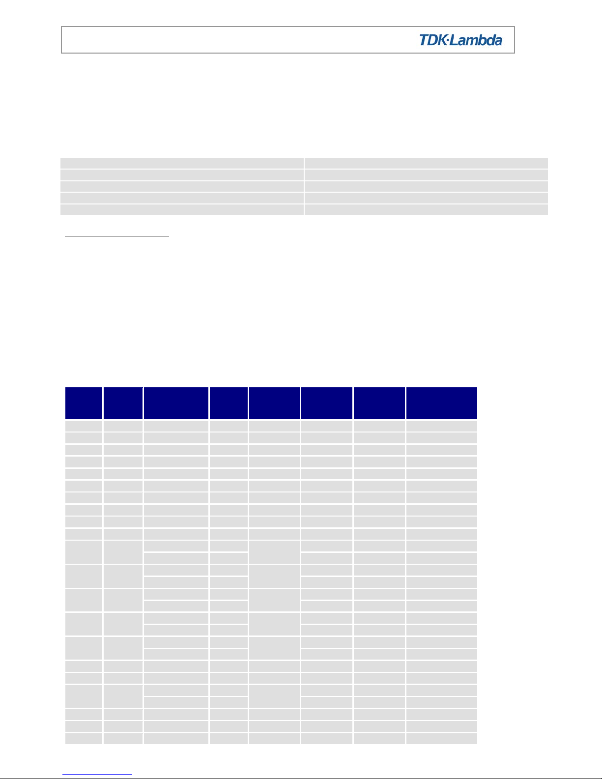
Standard modules:
Module
Note
Output range
Current
Occupied
Slots
Turns
Max
Current
Limit
Setting for
Hazardous
Energy
A 4.5-5.5V
60A 2 1
79.2A
>3V
AA 4.5-6.5V
60A 2 1
79.2A
>3V
AL 4.95-5.05V
60A 2 1
79.2A
>3V
B 4.5-5.5V
25A 1 1
33A
-
BB 4.5-6.5V
25A 1 1
33A
-
C
1, 8
5-16V
16A 1 2
21.2A
>11.3V
CM 8 5.2-6.6V
16A 1 2
21.2A
-
CL 8 4.75-5.3V
16A 1 2
21.2A
-
CH
1, 8
11.9-12.7V
16A 1 2
21.2A
>11.3V
D 8 18-29V
8A 1 4
10.6A
>.22.6V
E 2
5-16V
8A 1 2
10.6A
-
5-16V
8A 2 10.6A
-
EB
4.5-5.5V
9A 1 1
11.9A
-
4.5-5.5V
9A 1 11.9A
-
EH 2
11.9-12.7V
8A 1 2
10.6A
-
11.9-12.7V
8A 2 10.6A
-
EL 2
5.2-6.6V
8A 1 2
10.6A
-
11.9-12.7V
8A 2 10.6A
-
EQ
4.5-5.5V
9A 1 1
11.9A
-
2.7-3.9V
9A 1 11.9A
-
F 8 9-16V
33A 2 2
43.6A
>5.5V
G 8 17.5-29V
25A 2 4
33A
>7.2V
H 3
18-32V
5A 1 4
6.6A
-
18-32V
5A 4 6.6A
-
J
5,8,9
30-48V
10A 2 4
13A
>18.4V
K 8 18-29V
15A 2 4
19.8A
>12V
L
8,10
1.8-3.2V
25A 1 1
33A
-
Page 16

Page 16 of 20 17130 i ssue 31, June 2014
Alpha 600 Handbook
Module
Note
Output range
Current
Occupied
Slots
Turns
Max
Current
Limit
Setting for
Hazardous
Energy
M 8 5-16V
8A 1 2
10.6A
-
N
6,8
18-32V
5A (8) 1 4
6.6A
-
P 4
18-29V
5A 1 4
6.6A - 5-16V
8A 2 10.6A
-
PL 4
23.5-24.5V
5A 1 4
6.6A
-
4.75-5.3V
8A 2 10.6A
-
Q 8 2.7-3.9V
25A 1 1
33A
-
R 8 2.7-3.9V
60A 2 1
79.2A
>3V
S
7,8
2.5-5.7V
85A 2 1
110.5A
>2.2V
T 8 1.8-3.2V
60A 2 1
79.2A
>3V
U 8 10-21V
16A 1 3
21.2A
>11.3V
W 4.5-5.5V
15A 1 1
19.8A
- Z
4.5-5.5V
25A 1 1
33A
-
Additional module limitations:
Notes:
1) For C, CH, modules the max output current is 12A for voltages > 12V.
2) For E, EH, EL modules the max output current is limited to 7A in slot 3 and 6A in Slot 4.
3) For H modules the max output current is limited to 4A in slot 4. For voltages >29V, the output current is
limited to 1A
4) For P, PL modules the max output current is limited to 5A for channel 1 and for channel 2, 8A in slot 1, 7A in
slots 2, 3 and 5, and 6A in slot 4.
5) For J modules output current derates by 0.25A per volt above 40V.
6) N modules with output voltage greater than 29V have max output current of 1 Amp.
7) For S modules the max output current is limited to 75A in slots 2 & 3, 77A in slots 3 & 4, & 80A in slots 4 & 5.
8) When using remote sense, the max output voltage will be reduced by 0.5V for L, S, T, Q and R modules, and
by 1.0V for C, CH, CL, CM, D, F, G, J, M, K, N, U modules.
9) Ampere turns for J module is calculated as AT = (output current + 15A) x 4.
10) For L modules the max. output current is limited to 20A in slot 5.
11) Adjusting output voltage beyond the stated range may cause overvotage protection (OVP) to operate,
whereby all outputs will turn off. To reset OVP, turn back output voltage adjustment and remove the mains
supply for 30 seconds and then switch back on.
Unit limitations:
i) For PSUs fi tted with RA option (reverse air fl ow), the output is limited to 475W and 100AT at a max ambient
of 400C, or 400W, 85AT for a max ambient of 500C (horizontal only). Operation in any vertical position is not
permitted.
ii) For PSUs fitted with the LSF option, the output is limited to 400W and 88.9AT. The QF option is limited to
600W and 120AT.
iii) For power supplies having input or output connector housings fitted there is no effect on ratings in any
orientation.
SELV and Outputs Connected In Series:
Outputs can be connected in series thus producing non-SELV levels, or in parallel thus producing new energy
hazards, and this must be taken into account in the end-use application. When non-seriesed outputs are earthed
in the end use equipment they are SELV. If the outputs are not earthed they must be considered hazardous, as
a single fault in the secondary may make them exceed the SELV limits between output and earth. If any output
is non-SELV then all outputs become non-SELV.
All outputs have operational spacings to earth, and due consideration must be given to this in the end product
design.
Page 17

Page 17 of 20 17130 i ssue 31, June 2014
Alpha 600 Handbook
Custom Model:
Model: CA600 18G (NS-WAK-001)
Input voltage range: 90-264Vac
Outputs 18V 25A (450W, 100AT total)
Ambient 50°C max
Orientations All except psu vertical with airf lo w dow n war ds and psu upside down
Model NS-WAK-001 is identical to Model Alpha 600 18G.
Both Models are identical to the standard product, except they may be fitted with a Papst 612NGM fan.
Input Connections:
Input tabs- 6.3mm x 0.8mm, tin plated brass, rated 15A.
Mating input faston connectors
Brand
Colour
Wire size (awg)
Part number
Current rating
Amp
Red
22 - 18
2-520407-2
15A
Amp
Blue
16 - 14
3-520408-2
15A
Output Connections:
Output Connector Ratings:
1) 6.35mm fastons are rated at 15A.
2) 9.5mm Faston terminals are rated at 32A (tab thickness = 1.0mm, suitable Faston terminals are AMP 151667-2 or
AMP 280223-2)
3) M5 screw terminals are rated at 100A subject to the wire and wire connector used to connect them. Maximum
recommended torque setting for M5 screws is 2.4 – 2.6Nm.
Page 18

Page 18 of 20 17130 i ssue 31, June 2014
Alpha 600 Handbook
Page 19
Page 19 of 20 17130 i ssue 31, June 2014
Alpha 600 Handbook
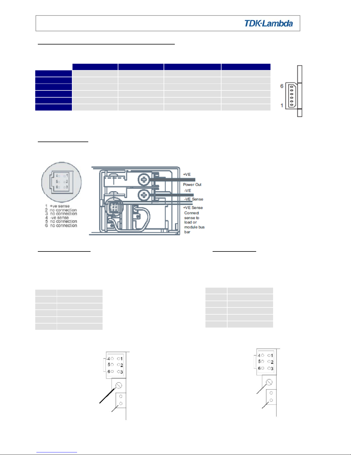
Option: mains fail options (MF, MFL, MFE, MFU, MFV)
Connector: Six way Molex, 50-37-5063. Crimp terminals: 08-70-1040.
Option: PP- Parallel
Connector: Six way Molex, 90142-0006. Crimp terminals: 90119-2109.
Option: PA- Parrallel Option IN- inhibit
Connector: Connector:
Six way Molex, 90142-0006. Six way Molex, 90142-0006.
Crimp terminals: 90119-2109. Crimp terminals: 90119-2109.
MF/MFL
MFE
MFU
MFV
Pin 1
Inhibit Low
Enable Low
Inhibit Low
Inhibit Low
Pin 2
+5V Aux
+5V Aux
+5V Aux
+5V Aux
Pin 3
Power Fail
Power Fail
Power Fail Emitter
AC Fail
Pin 4
0V Aux
0V Aux
0V Aux
0V Aux
Pin 5
Inhibit High
Enable High
Inhibit High
Inhibit High
Pin 6
NC
NC
Power Fail Collector
SYS Reset
1
Not connected
2
Module Good
3
Inhibit input
4
Not connected
5
-ve O/P
6
-ve O/P
1
+ve sense
2
Module Good
3
Star Point
4
-ve sense
5
-ve power
6
Star Point
Module good
adjustment pot
Module good link (J3)
Module good
adjustme nt pot
Module good link (J3)
Page 20

Page 20 of 20 17130 i ssue 31, June 2014
Alpha 600 Handbook
Option RP- Remote programming
For other options refer to application notes
Customer fixings:
1
+ve sense
2
-ve sense
3
Control 2
4
NC 5 Control 1
6
NC
TDK-Lambda UK Ltd
Kingsley Avenue, Ilfracombe
Devon, EX34 8ES
Telephone - Sales and Service +44 (0)1271 856666
Head Office and Works +44 (0)1271 856600
Facsimile +44 (0)1271 864894
WEBSITE: www.uk.tdk-lambda.com
 Loading...