

Page 1

OPERATOR MANUAL FOR
802 Series High Voltage
POWER SUPPLY
Document: 83488001 Rev N
TDK-LAMBDA AMERICAS
405 Essex Road, Neptune, NJ 07753
Tel: (732) 922-9300
Fax: (732) 922-9334
Web: www.us.tdk-lambda.com/hp
Page 2

PAGE LEFT INTENTIONALLY BLANK
Page 3
83-000-005 Rev F
ONE YEAR WARRANTY
TDK-Lambda Americas
, Inc. (405 Essex Road, Neptune, N.J. 07753), warrants that the unit is free from defects in
material or workmanship for a period of ONE YEAR from the date of initial shipment.
TDK-Lambda Americas
Inc.
will
service and,
at its option, repair or replace parts which prove to be defective. This will be done free of charge during
the stated warranty period. This warranty excludes defects resulting from mi
s
use, unauthorized modification,
operation outside the environmental or
safety specifications of the power supply, or improper site preparation or
maintenance. The customer shall contact
TDK-Lambda Americas Inc.
, for warranty service or repair as described in
the RETURNING EQUIPMENT section. The customer shall prepay shipping
charges. If the unit is covered under the
foregoing warranty, then
TDK-Lambda Americas Inc.
shall pay the return shipping charges.
The “WARRANTY”, “CLAIM FOR DAMAGE IN SHIPMENT”, and “RETURNING EQUIPMENT” i
n
formation applies to
equipment purchased directl
y from
TDK-Lambda Americas Inc
. End users receiving equi
p
ment from a third party
should consult the appropriate service organization for assistance with these issues.
THIS LIMITED WARRANTY IS IN LIEU OF, AND
TDK
-
LAMBDA AMERICAS INC.
DISCLAIMS AND EXCLUDES
,
ALL OTHER WARRANTIES, STATUTORY, EXPRESS OR IMPLIED, INCLUDING, WITHOUT LIMITATION, ANY
WARRANTY OF MERCHANTABILITY OR FITNESS FOR A PARTICULAR PURPOSE, OR OF CONFORMITY TO
MODELS OR SAMPLES.
CERTIFICATION
All test and measuring equipment used by
TDK-La
mbda Americas
Inc.
for Final Acceptance Testing are traceable to
primary standards certified by the National Institute of Standards and Technology.
LETHAL VOLTAGES PRESENT!
All power supplies contain hazardous voltage and energy. The power supply must
only be operated by qualified
personnel who have read this operator’s manual and are familiar with the operation, hazards and application of the
power supply. Proper care and jud
g
ment must always be observed.
1.
Before connecting input AC power, ensure all c
overs are in place and securely fastened. E
n
sure the required
safety ground to chassis is installed and sufficient cooling is su
p
plied.
2.
Proper grounding from the input AC power is required to reduce the risk of electric shock, and to comply with
safety age
ncy and code requirements.
3.
Use extreme caution when connecting input AC power. Only apply the input voltage specified on the rating label.
4.
Use extreme caution when connecting any high voltage cables. Never handle any output c
a
bles when the power
supply is
operating.
5.
After a power supply is switched OFF, its output section will retain a charge which may be lethal. Allow sufficient
time for self
-
discharge before handling anything connected to the output. The di
s
charge time specified in the
Safety Notes does
NOTinclude extra time required to discharge the energy stored in the user’s load.
6.
When user serviceable fuses are present, always replace fuses with the same type and Volt/Amp ra
t
ing.7.Never attempt to operate the power supply in any manner not described in
this manual.
8.
Never remove DANGER or WARNING labels from the power supply. Replace lost or damaged labels
immediately. Contact
TDK-Lambda Americas
Customer Service for replacement labels.
9.
The power supply may be serviced only by
TDK-Lambda Americas Inc.
fa
ctory qualified service personnel.
Breaking the warranty seal will void the warranty. Prior to opening the power supply, contact
TDK-Lambda
Americas
Inc.
Customer Service for a written Service Waiver and a replacement warranty seal.
Page 4

TDK-Lambda
MANUFACTURER'S PRODUCT DECLARATION
INTENDED PURPOSE (USE)
The Power Supplies described by this manual are defined by TDK-Lambda Americas Inc.
as a component for use in the composition of an apparatus as defined in Article 1 (1) of
the EMC Directive (89/336/EEC). These products, as individual components, do not
perform in themselves a direct function for the user of the end product. They are not
intended to be placed on the market with a direct function to a final user! As such, the
products described by this manual are not subject to the provisions of the EMC Directive
(89/336/EEC, with amendment 92/31/EEC).
The products described by this manual are intended for incorporation into a final product
by a professional assembler. It is the responsibility of the assembler to ensure that the
final apparatus or system incorporating our products complies with all relevant EMC
standards for that final product.
OPERATING ENVIRONMENT
The operating environment as defined by TDK-Lambda Americas Inc., for the products
described by this manual is stated as follows:
The Power Supplies described by this manual are intended for use in a protected
industrial environment or in proximity to industrial power installations. These locations are
often referred to as industrial locations containing establishments that are not connected
to the low voltage public mains network.
Industrial locations are characterized by the existence of one or more of the following
conditions:
1) industrial, scientific and medical (ISM) apparatus are present;
2) heavy inductive or capacitive loads are frequently switched;
3) currents and associated magnetic fields are high;
4) location supplied by their own transformer.
These components are not intended for connection to a public mains network, but are
intended to be connected to a power network supplied from a high or medium-voltage
transformer dedicated for the supply of an installation feeding manufacturing or similar
operations. They are suitable for use in all establishments other than domestic and those
directly connected to a low voltage power supply network which supplies buildings used
for domestic purposes.
Page: 83-000-006 Rev D
Page 5
TDK-Lambda
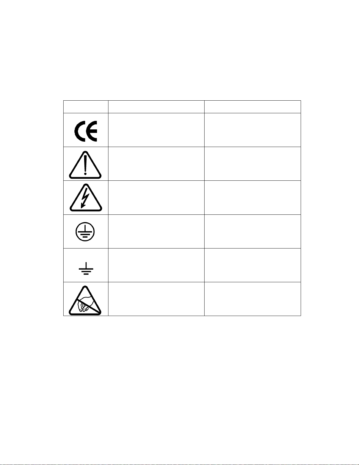
Description of symbols used in product labeling
SYMBOL PUBLICATION DESCRIPTION
EC Council
Directive 93/68/EEC
European Community
Conformity Assessment
Product Mark
IEC 348 Attention, consult
Accompanying documents
IEC 60417-1-5036 Dangerous voltage
IEC 60417-1-5019 Protective earth
(e.g. power line earth ground)
IEC 60417-1-5017 Functional earth
IEC 60417-1-5134 Electrostatic Discharge
(e.g. chassis ground)
(ESD) Sensitive Device
Page: 83-000-007 Rev E
Page 6

ELECTRICAL STANDARDS
All company primary standards are either certified or are traceable to certification by the
National Institute of Standards and Technology.
CLAIM FOR DAMAGE IN SHIPMENT
This instrument received comprehensive mechanical and electrical inspection before
shipment. Immediately upon receipt from the carrier, and before operation, this instrument
should be inspected visually for damage caused in shipment. If such inspection reveals
damage in any way, a claim should be filed with the carrier. A full report of damage should
be obtained by the claim agent and this report should be forwarded to us. We will then
provide a disposition of the equipment and arrange for repair or replacement.
When referring to this equipment, always include the model and serial numbers.
The “WARRANTY”, “CLAIM FOR DAMAGE IN SHIPMENT”, and “RETURNING
EQUIPMENT” information applies to equipment purchased directly from TDKLambda Americas Inc. End users receiving equipment from a third party should
consult the appropriate service organization for assistance with these issues.
RETURNING EQUIPMENT
Before returning any equipment to the factory, the following steps shall be taken.
1.
Notify TDK-Lambda Americas Inc. at 732-918-6888 or follow the instructions at
www.US.TDK-Lambda.com/HP/service.htm. Give a full description of the difficulty
including the model and serial number of the unit in question. Upon receipt of this
information, we will assign a Return Material Authorization (RMA) number and
provide shipping instructions.
2.
The customer shall prepay shipping charges. Equipment returned to us must be
packed in a manner to reach us without damage. The shipping container must be
marked with the RMA number in an area approximate to the shipping label with
numbers that are easy to read. All returned units that do not show the RMA number
on the outside of the container will be refused.
If the equipment is repaired within the warranty agreement, than TDK-Lambda
Americas Inc. shall pay for the return shipping to the customer.
3.
For non-warranty repairs, we will submit a cost estimate for your approval prior to
proceeding. The customer shall pay return shipping charges.
MECHANICAL INSTALLATION
Most power supplies are heavy and, when rack mounted, they should be supported by
rails along the sides of the supply from front to rear. The rails must adequately support the
unit and not block airflow. Do not support the power supply from the front panel only.
Page: 83-000-011 Rev K
Page 7

Table of Contents
1. GENERAL INFORMATION ................................................................................. 5
1.1. User Manual Content .......................................................................................... 5
1.2. Introduction ......................................................................................................... 5
1.3. 802 Overview ...................................................................................................... 6
1.4. Capacitor Charging Technology .......................................................................... 6
1.5. Continuous DC Operation ................................................................................... 7
1.6. Additional Features: ............................................................................................ 7
1.7. Safety Precautions .............................................................................................. 7
1.8. Model Number Format ........................................................................................ 8
2. SPECIFICATION ................................................................................................. 9
2.1. Average Charging Power .................................................................................... 9
2.2. Peak Charging Power ......................................................................................... 9
2.3. Average DC Power .............................................................................................. 9
2.4. Output Voltage Range ......................................................................................... 9
2.5. Polarity ................................................................................................................ 9
2.6. HV Output Cable ................................................................................................. 9
2.7. HV Insulating Medium ......................................................................................... 9
2.8. AC Input Voltage ................................................................................................. 9
2.9. AC Input Current ................................................................................................. 9
2.10. AC Connector ...................................................................................................... 9
2.11. AC Line Contactor ............................................................................................... 9
2.12. Power Factor ....................................................................................................... 9
2.13. Efficiency ............................................................................................................. 9
2.14. Front Panel.......................................................................................................... 9
2.15. Stability ............................................................................................................... 9
2.16. Temperature Coefficient ...................................................................................... 9
2.17. Stored Energy ................................................................ ..................................... 9
2.18. Pulse to Pulse Repeatability ................................................................................ 9
2.19. Dimensions - inches (mm) ................................................................................... 9
2.20. Weight - lbs (kg) .................................................................................................. 9
2.21. Ambient Temperature .......................................................................................... 9
2.22. Altitude ................................................................................................................ 9
2.23. Humidity .............................................................................................................. 9
2.24. Protection ................................................................ ............................................ 9
2.25. Remote Control (all models) ................................................................................ 9
2.26. Accessories ......................................................................................................... 9
2.27. Options .............................................................................................................. 10
2.28. Ordering Info ..................................................................................................... 10
2.29. Ordering Examples ............................................................................................ 10
3. OUT OF BOX INSPECTION ............................................................................. 11
3.1. Visual Inspection ............................................................................................... 11
3.2. Electrical Inspection .......................................................................................... 11
3.3. Contacting TDK-Lambda Americas Customer Service ...................................... 12
3.4. Returning Defective Units .................................................................................. 12
4. INSTALLATION ................................................................................................. 13
4.1. 19-Inch Rack Mounting ..................................................................................... 13
4.2. Ventilation Requirements .................................................................................. 15
4.3. Orientation......................................................................................................... 15
4.4. AC Power Connection ....................................................................................... 15
1
83488001 Revision N
Page 8

4.5. Connecting the High Voltage Output ................................................................. 17
5. CONTROLS, INDICATORS, CONNECTORS ................................................... 19
5.1. Front Panel Layout (L Model) ............................................................................ 19
5.2. HV ON Push Button (Ref 1) ............................................................................... 20
5.3. Status LEDs (Ref 2) .......................................................................................... 20
5.4. Local Voltage Set (Ref 3) .................................................................................. 21
5.5. Voltage bar graph (Ref 4) .................................................................................. 21
5.6. Voltage Display (Ref 5) ..................................................................................... 21
5.7. HV OFF Push Button (Ref 6) ............................................................................. 21
5.8. Off/Local/Remote Keyswitch (Ref 7) .................................................................. 21
5.9. View set push button (Ref 8) ............................................................................. 21
5.10. Current bar graph (Ref 9) .................................................................................. 21
5.11. Current Display (Ref 10) .................................................................................... 22
5.12. Power switch (Ref 11) ....................................................................................... 22
5.13. Front Panel Layout (S Model) ............................................................................ 22
5.14. Front Panel Layout (OEM Model) ...................................................................... 22
5.15. Rear Panel Layout (L Models) ........................................................................... 23
5.16. Rear Panel Layout (S Models)........................................................................... 25
5.17. Rear Panel Layout (OEM Models) ..................................................................... 26
5.18. REMOTE CONTROL CONNECTOR PIN DIAGRAM ........................................ 27
6. OPERATING INSTRUCTIONS .......................................................................... 29
6.1. Local Operation (802L only) .............................................................................. 29
6.2. Remote Operation (All models) ......................................................................... 30
6.3. Remote Control Sequence ................................................................................ 33
6.4. Parallel Operation.............................................................................................. 34
7. APPLICATION NOTES ..................................................................................... 39
2
83488001 Revision N
Page 9

List of Figures
Figure 1. 802L Front View ................................................................................................ .................. 13
Figure 2. 802L Rear View .................................................................................................................. 14
Figure 3. 802L Side View ................................................................................................................... 14
Figure 4 AC Input Terminal Block ..................................................................................................... 16
Figure 5 Typical Load Circuit Connection .......................................................................................... 17
Figure 6 802L Front Panel Controls and Indicators ........................................................................... 19
Figure 7 Front Panel Controls and Indicators (S Model) .................................................................... 22
Figure 8 802L Rear Panel Connections ............................................................................................ 23
Figure 9 802S Rear Panel ................................................................................................................. 25
Figure 10 802OEM Rear Panel ......................................................................................................... 26
Figure 11 Remote Interface Connector and Signals. ......................................................................... 27
Figure 12 Suggested external remote interface circuit. ..................................................................... 31
Figure 13 Typical remote Interface waveforms .................................................................................. 34
Figure 14 802L Parallel System Control Connections. ...................................................................... 35
Figure 15 802L and 802S/OEM Parallel System control Connections. .............................................. 36
Figure 16 Parallel Operation Connections for 802S/OEM Supplies ................................................... 37
List of Tables
Table 1 :802 Model Description Format . ............................................................................................. 8
Table 2 Recommended AC Input Cable ............................................................................................. 16
Table 3 Front Panel Controls and Indicator Functions (L Model) ........................................................ 19
Table 4 Front Panel Controls and Indicators (S Model) ...................................................................... 22
Table 5 802L Rear panel Functions ................................................................................................... 23
Table 6 802 Remote Interface Description ........................................................................................ 31
3
83488001 Revision N
Page 10

Notes
4
83488001 Revision N
Page 11

1. GENERAL INFORMATION
1.1. User Manual Content
This User’s Manual contains the operating instructions, installation instructions and
specifications for the ALE 802 series high voltage power supply. The instructions refer to
standard power supply models, and include checkout, installation, and operation of the 802
series. Suggestions and requirements for connecting AC power, load cables and signal
cables are given. Various operating modes and programming modes are described.
The model 802 is just one model in a broad family of HV power supplies covering the power
range from 500J/sec to 30kJ/sec in a single package, and to 1MW and beyond in parallel
systems. For more information please visit our web site at:
http://www.us.tdk-lambda.com/hp/product_html/high_volt.htm.
This manual contains information, instructions and diagrams which apply to standard
constructions. If special features or modifications have been installed, the instructions
specific to that modification are contained in Addenda and take precedence if conflicts
exist. Please take care to refer to the correct information for your unit.
NOTE
1.2. Introduction
TDK-Lambda Americas ALE model 802 are state of the art constant current switch mode
high voltage power supplies, designed to rapidly and efficiently charge capacitors in laser
systems, modulators, pulse forming networks, and a broad range of pulse generator circuits,
without the need for a series current limiting resistor. They can also be used in many
continuous DC applications including beam power for RF devices such as magnetrons,
gyrotrons, klystrons and electron beam loads.
The 802 series utilize a high frequency IGBT based series resonant inverter topology which
operates as a constant current source. This makes the supply perfect for rapidly charging
capacitors which represent a challenging load for conventional HV DC supplies using
multiplier designs.
The 802 series is available with a choice of three different front panel configurations
designed to suit different applications and end uses. All models feature the same
comprehensive remote control interface which is detailed in Section 6.2.
The 802L Model is fully instrumented with front panel meters displaying output voltage and
current, status LEDs, a key switch for OFF, LOCAL or REMOTE operation, HV ON/OFF
push-button switches, and a 10 Turn output voltage control. The rear panel features external
interlock, inhibit, remote control and slave (parallel operation) control connections.
The 802S Model can only be operated by remote control and features only status LEDs and
a power switch on the front panel. The "S" Models have been designed to operate as a slave
unit to the "L" Models or in systems where local control is not a requirement.
The 802OEM features a blank aluminum front panel and can only be operated by remote
control.
As many 802 supplies as required, can be connected in parallel to provide greater output
power.
5
83488001 Revision N
Page 12

1.3. 802 Overview
1.3.1. Features
8kJ/sec capacitor charging power, 8kW in continuous DC applications.
Output voltages from 0-1kV to 0-50kV.
Rep rates from single shot to kilohertz.
Local (L Model) or remote operation with comprehensive control interface.
Cost effective blank front panel version for OEM applications.
Constant current topology for rapid efficient charging.
Parallel operation (master/slave) for high power applications.
Compact Air Cooled design.
Passive Power Factor Correction reduces RMS current draw.
1.3.2. Benefits
Lightweight switchmode design.
Rack mount chassis configuration.
Low stored energy provides greater safety.
Constant current design eliminates series current limit resistance in charge circuit.
Immunity to external EMI.
1.3.3. Applications
Charging capacitors and capacitor banks.
Powering pulse forming networks/modulators.
Powering lasers: Excimer, flashlamp pumped dye, Yag, CO2, etc.
Continuous power for RF tubes – magnetron, gyrotron, TWT, klystron etc.
Electron beam applications.
DC power source for pulsed hard-tube and solid state modulators.
1.4. Capacitor Charging Technology
Capacitor charging applications require a power supply designed specifically for the task.
The 802 series supplies allow capacitors to be charged in pulse forming networks and
modulators in a very fast, efficient and controllable manner.
The units are compact high power constant current sources that can linearly and rapidly
charge a capacitive load to high voltage. Once the load capacitor is charged to the
programmed voltage, the supply will switch over to a voltage regulation mode and maintain
the load voltage at the programmed level until it is discharged.
The flexible design of the 802 allows the unit to be ordered with (L model) or without (S and
OEM model) the front panel controls and meters. Front panel controls are ideal in
applications where local control and read backs are necessary, such as R&D, laboratory
use and diagnostics. All front panel controls and indicator signals are available at the rear
panel remote control connector regardless which panel option (L, S, or OEM) is selected.
The unit is self-contained, requiring only AC power and appropriate controls. Several units
may be connected in parallel for higher power operation. There is no theoretical limit to the
number of units that may be paralleled. Typically one master unit and one or more slave or
OEM units may be used to obtain as much output power as necessary. The 802 is also
ideally suited to charge reservoir capacitors in resonant charging circuits where high rep
rates (several kilohertz) are required, such as in metal vapor lasers or solid-state
modulators.
6
83488001 Revision N
Page 13
All 802 power supplies are designed to minimize the risk of fire or shock
hazard. This instrument received comprehensive mechanical and
electrical inspection prior to shipment. Nevertheless, certain safety
precautions must be observed. Only TECHNICALLY QUALIFIED
SERVICE PERSONNEL familiar with the principles of electrical safety
should operate this supply. The power supply SHOULD NOT BE
EXPOSED TO WATER OR MOISTURE OR DUSTY ENVIRONMENTS.
Electrical safety must be maintained at all times.
Lethal voltages are developed within the power supply's enclosure and
at the output cable. Therefore, the cover may not be removed by the
user (see Warranty in preamble section for variance). Also, the large
capacitors in the supply may store power even after the AC input line is
removed. ALLOW AT LEAST 40 SECONDS DISCHARGE TIME
between removing the AC input line and opening the cover. ALSO,
ALLOW AT LEAST 40 SECONDS between switching the AC power off
and switching it on again.
1.5. Continuous DC Operation
Although the 802 series has been designed for capacitor charging applications, they can
also be used as a continuous DC High Power Source for RF tubes such as klystrons,
TWTs, or other DC loads such as DC-DC converters. The DC option must be specified
when ordering, and the supply will be factory setup and tested with a continuous DC load.
When 802 supplies are operated in continuous DC applications it is often necessary to add
an external capacitor between the load and ground to improve the ripple performance of
the unit. Our online Application Note 505 describes operating capacitor charging supplies
in DC applications, and gives guidance in determining the size of any additional external
filter capacitance required. App Note 505 can be found at:
http://www.us.tdk-lambda.com/hp/pdfs/application%20notes/93008505rC.pdf
Consult the factory before connecting parallel units in continuous DC applications.
1.6. Additional Features:
Internal contactor and fuses for AC disconnect and protection
Standard AC power and control connectors
Documentation Manual Including -
Installation, check out, suggested remote interfaces and control circuits
10 ft (3m). Output cable is standard, other lengths are optional.
1.7. Safety Precautions
1.7.1. This product is designed for Indoor use.
1.7.2. This product is designed for pollution degree 2.
1.7.3. This product is designed for Transient Overvoltage Category II
1.7.4. Ensure all covers are in place and securely fastened before switching ON the AC
power.
1.7.5. Proper grounding from the input AC power is required to reduce the risk of electric
shock. Ensure that the AC Protective Earth Ground connection has at least the same
gauge wire as the supply leads shown in Table 2.
83488001 Revision N
7
Page 14
1.7.6. Use extreme caution when connecting AC input power, and never apply the incorrect
input voltage, refer to ratings label.
1.7.7. Use extreme caution when connecting the high voltage output cable to the load.
1.7.8. Ensure all load capacitors are completely discharged prior to connection. Never
handle the output cable when the power supply is operating.
1.7.9. Never attempt to operate the power supply in any manner not described in this
manual.
1.7.10. Never remove DANGER and WARNING labels from the power supply. Replace lost
or damaged labels immediately.
1.7.11. The power supply should only be serviced by factory authorized personnel.
1.7.12. No user maintenance is required.
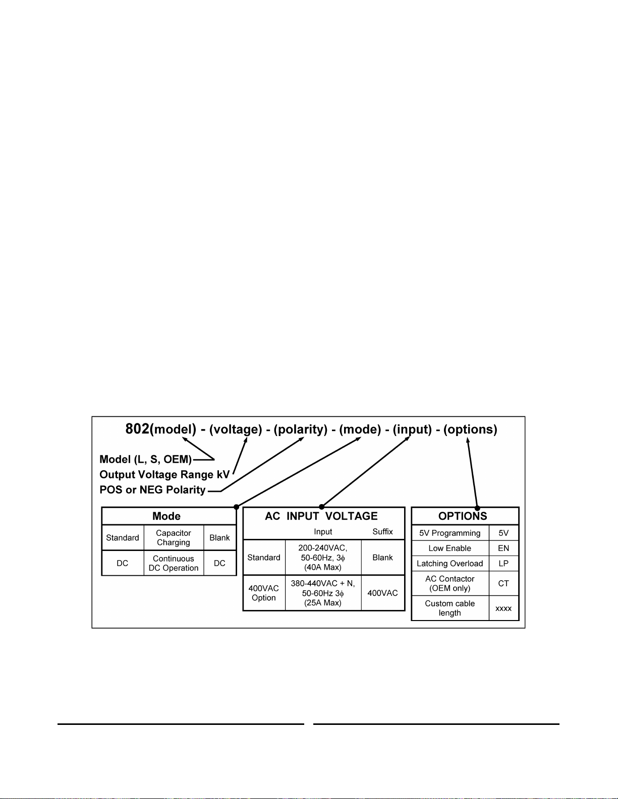
1.8. Model Number Format
The model numbering system for the 802 Series power supply includes symbols for features
and options. They are separated by dashes.
Examples are: 802L-10kV-POS-400VAC and 802S-20kV-POS-DC.
The 802 is available with three front panel configurations, the L, S, and OEM. The choice of
panel configuration is dependent upon the installation and system requirements. See section
5 for further details.
Table 1 shows a partial listing of the model description format for the 802 Power Supply
family. For additional options, the customer may contact the Sales Department at TDKLambda Americas. Special options are typically shown as a four-digit suffix to the model
number.
Table 1 :802 Model Description Format .
8
83488001 Revision N
Page 15

2.1. Average Charging Power
8,000 Joules/sec (½CV2 x Rep Rate)
2.2. Peak Charging Power
9,000 Joules/sec (½CV
2 ∕
t
charge
)
2.3. Average DC Power
8,000 Watts
2.4. Output Voltage Range
1, 2, 4, 5, 10, 15, 20, 30, 40, 50kV, variable from 10-100% of rated.
Other voltages on request, please contact the factory.
2.5. Polarity
Available as fixed Positive or Negative. Please specify at time of ordering
2.6. HV Output Cable
1-39kV Models - DS2124 Coaxial cable with proprietary HV connector
40-50kV Models - DS2214 Coaxial cable with proprietary HV connector
2.7. HV Insulating Medium
Exxon Mobil Univolt N61B or equivalent insulating oil
2.8. AC Input Voltage
200-240VAC (180-264), 3Ø or 380-440VAC (340-460), 3Ø + N, 50-60Hz
Please specify at time of ordering
2.9. AC Input Current
40A for 200-240VAC Input / 25A for 380-440VAC input
2.10. AC Connector
UL/CSA approved terminal block. 3Ø + GND for 200-240VAC, 3Ø + N +
GND for 380-440VAC
2.11. AC Line Contactor
UL/CSA approved AC line contactor (standard on 802L and 802S, option for
802OEM)
2.12. Power Factor
Passive PFC pf = 0.85 at full load and nominal AC line
2.13. Efficiency
Better than 85% at full load
2.14. Front Panel
802L - Voltage Control, Voltage & Current Meters, Status Indicators
802S - On/Off Switch, Status Indicators
802-OEM - Blank front panel
2.15. Stability
0.2% per hour after 1 hour warmup
2.16. Temperature Coefficient
100ppm per °C typical
2.17. Stored Energy
Less than 0.3J all models
2.18. Pulse to Pulse Repeatability
±2% to 1000Hz, consult factory for higher rep rates
2.19. Dimensions - inches (mm)
19 (483) W x 8.75 (222) H x 17 (432) D
2.20. Weight - lbs (kg)
80 (37)
2.21. Ambient Temperature
Storage: -20 to +70°C. Operating: -20 to +45°C
2.22. Altitude
Storage: 40,000ft (12,000m), Operating: 9,900ft (3,000m)
2.23. Humidity
10-90%, non-condensing
2.24. Protection
Open/short circuits, Overloads, Arcs, Overtemp, Overvoltage, Safety
Interlock
2.25. Remote Control (all models)
Via 25-pin D-sub connector on rear of unit, Signals include, Vprogram (010V), HV Enable/Reset, Inhibit, Summary Fault, Load Fault, Vanalog, Vpeak
2.26. Accessories
10ft HV cable, operating manual
2. SPECIFICATION
83488001 Revision N
9
Page 16

2.27. Options
EN - Low Enable. Replaces standard high enable
5V - 0-5V Analog programming. Replaces standard 0-10V programming.
LP - Latching Overload Protection, requires HV reset after overload fault
DC - Continuous DC operation
CT - AC line contactor (option for 802-OEM only, standard on 802L and
802S)
Double terminated HV cable, and mating bulkhead connector
2.28. Ordering Info
Model - XXkV - POS (or NEG) - YYYVAC - ZZ (options)
2.29. Ordering Examples
802L-10kV-POS, 802S-1kV-NEG-DC, 802-OEM-50kV-POS-400VAC
All specifications subject to change without notice
83488001 Revision N
10
Page 17

3. OUT OF BOX INSPECTION
3.1. Visual Inspection
Prior to shipment, this instrument was inspected and found to be free of mechanical and
electrical defects. As soon as the unit is unpacked, inspect for any damage that may have
occurred in transit. Verify the following:
a) Check the operation of the front panel control (knob should rotate smoothly).
b) Confirm that there are no dents or scratches on the panel surfaces.
c) Check front panel meters and LEDs for any broken or cracked lenses.
If any damage is found, follow the instructions in Section 3.3.
3.2. Electrical Inspection
Before the power supply is installed in a system, verify that no internal damage occurred
during shipping. A set of simple preliminary electrical test can be performed if desired. These
tests are described below.
The sequences described are for L model supplies with local controls, for S and OEM
models the corresponding signals must be applied and monitored through the remote control
NOTE
interface.
3.2.1. Test 1
Purpose: Verify general logic operation, generate maximum output current, and check
overload protection circuits. With AC power "OFF" and disconnected, short the HV
output by connecting the center conductor of the output cable to its return shield
(braid). This dead short will allow the unit to generate full output current at zero voltage.
1. Set the output voltage control to zero. Connect AC power to the unit. Turn "ON" the
AC power front panel switch.
2. Turn the front panel keyswitch to the LOCAL position (if applicable). Press the HV
"ON" button and turn up the HV control until the power supply is generating output
current into the dead short. The current meter will indicate max. current. The
voltage meter will read zero and the power supply will intermittently turn on and off
indicating the "overload" condition. The unit should continue to indefinitely cycle in
this mode with a 1 second period. (The power supply will go into overload when
max. current is drawn for more than half a second). If the LP option is installed, the
unit will shut down and indicate a fault after delivering full current for 500milliS.
3. Turn off the HV and AC power switches.
This test indicates the inverter section is generating maximum current and the logic and
overload circuitry works correctly.
3.2.2. Test 2
Purpose: Verify that the power supply generates maximum rated voltage, and the
regulation and feedback circuits are functioning.
1. With AC power OFF and disconnected, connect an appropriate load capacitor to
the power supply output cable. Select the capacitor size so the charge time is
several milliseconds or more.
2. Prepare to charge the capacitor. NOTE: Operating a 802 power supply into an open
circuit (no load operation) will instantly damage the power supply's HV output
11
83488001 Revision N
Page 18

diodes. Make sure the load (capacitor) is connected and the HV output cable is
securely inserted and connected.
3. Turn the voltage control on the front panel all the way down to zero (counter
clockwise), apply AC power, turn the front panel keyswitch to the LOCAL position (if
applicable), and press the HV ON button. By turning up the HV control knob the
capacitor will charge to the voltage indicated on the front panel voltmeter. The
power supply may be turned all the way up to its max. output voltage provided the
load capacitor is sufficiently rated.
4. By turning the voltage control down or depressing the HV OFF button, the capacitor
will slowly "bleed" down through the internal voltage divider resistors used for
regulation feedback. Use an external discharge wand to ensure the capacitor is fully
discharged.
Test #2 indicates the HV section is working correctly. Tests 1 and 2 generally indicate
the unit is functioning as designed. Although 100% power had not been generated,
these two tests give greater than 90% confidence that the unit is not damaged.
If any inconsistency from the above test procedure is noted, do not hesitate to call TDKLambda Americas Customer Service for assistance.
3.3. Contacting TDK-Lambda Americas Customer Service
When contacting customer service locate the product description, part number and serial
number from the label located on the rear of the unit, and have this information available.
Phone: (732) 922-9300 E-mail: hp.service@us.tdk-lambda.com
Fax: (732) 922-1441
Customer Service, or an approved Service Center, should be contacted if:
The power supply is mechanically or electrically damaged.
The power supply requires on-site calibration, or replacement warning decals.
The customer has questions about a special application that is not described in this
manual.
Normally, the customer may NOT open any chassis covers that have a warranty seal.
Breaking a seal will void the warranty.
At the discretion of TDK-Lambda Americas, the customer may be granted permission to
break the warranty seal and open the chassis covers. Customer Service shall confirm the
permission by sending a replacement seal. Once the unit has been serviced, the customer
shall close the cover and apply the replacement seal adjacent to (not on top of) the broken
seal.
3.4. Returning Defective Units
If a unit needs to be returned to the factory for repair, the factory must first assign an RMA
number. Please complete and send the online RMA request form at http://www.us.tdk-
lambda.com/hp/RMA_request.htm and an RMA number will be assigned. Follow the return
instructions on the form or at http://www.us.tdk-lambda.com/hp/returns.htm.
12
83488001 Revision N
Page 19
Never install the 802 so its weight is supported only by the front panel
screws!
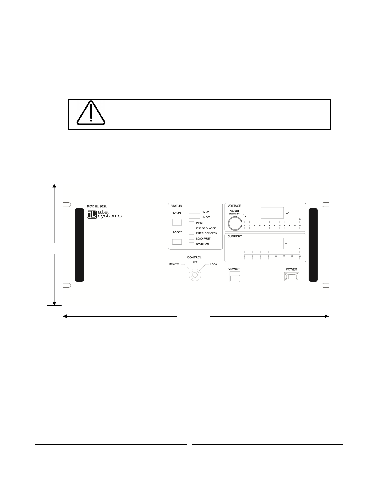
8.72”
(222mm)
19” (483mm)
4. INSTALLATION
4.1. 19-Inch Rack Mounting
This power supply is intended for mounting in a conventional 19-inch equipment rack. It’s
8.75 inch height makes it a “5U” size instrument. The rack should enclose the sides, top and
back to protect the operator from electrical shock and protect the supply from environmental
contamination.
The 802 must never be installed without support in the back or sides of the unit. The 802
should be mounted on support rails or chassis slides –such as General Devices CTS-124- or
on a suitable shelf or supports inside the rack.
The mechanical outline of the 802 is shown in Figures1 through 3.
Figure 1. 802L Front View
13
83488001 Revision N
Page 20
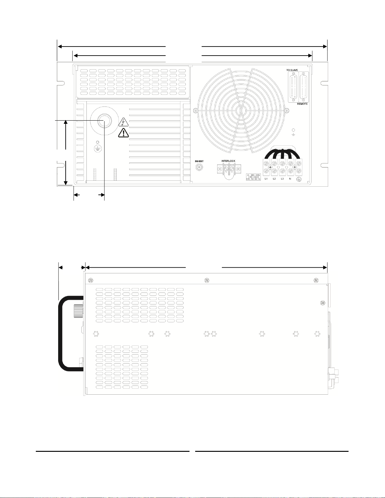
4.5”
(114mm)
2.15”
(55mm)
19” (483mm)
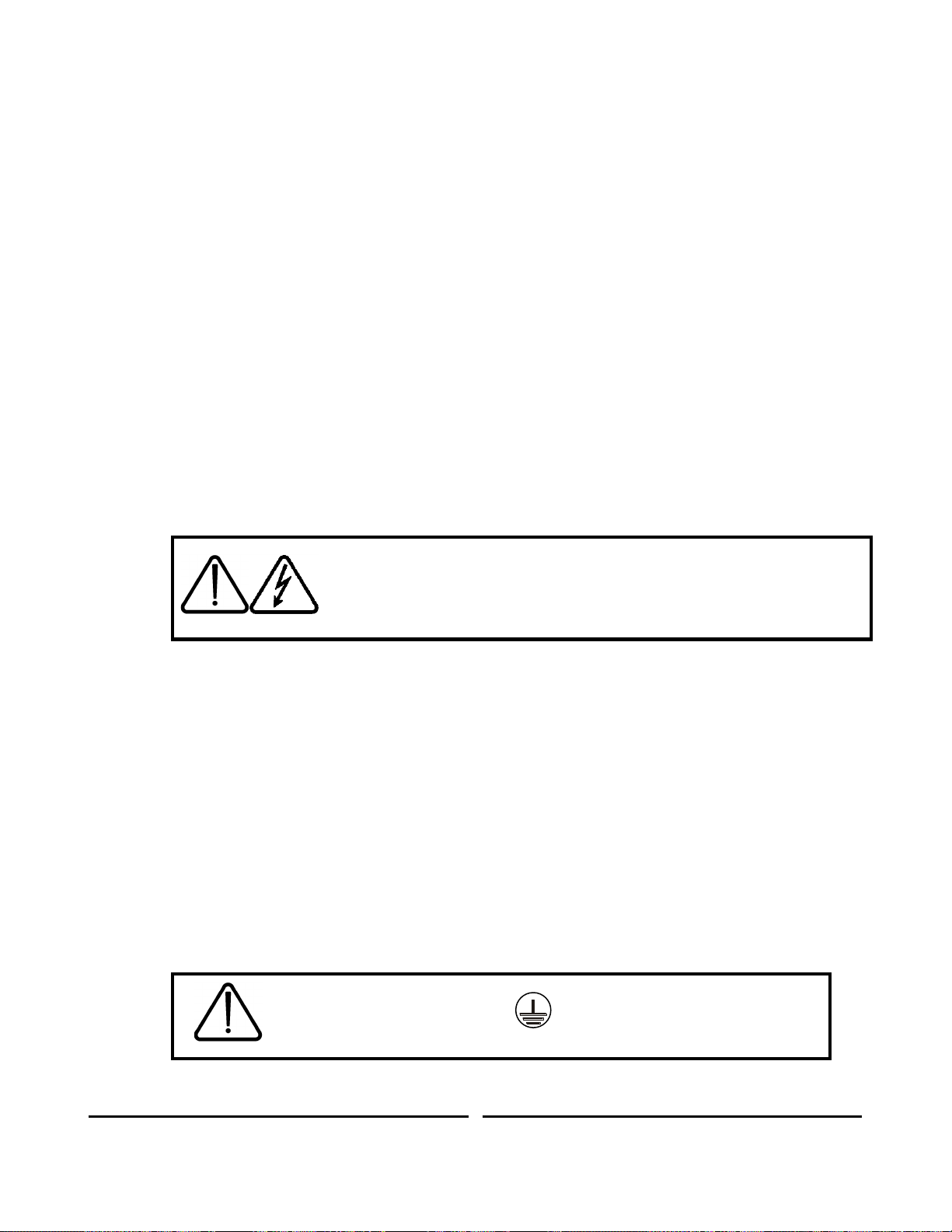
17” (432mm)
1.875”
(48mm)
17” (432mm)
Figure 2. 802L Rear View
Figure 3. 802L Side View
14
83488001 Revision N
Page 21
For 200-240VAC models, the maximum voltage allowed between any
two AC input terminals is 264VAC. For 380-440VAC models, the
maximum voltage allowed between any two AC input terminals is
460VAC. If this voltage is exceeded, catastrophic damage will result,
that is not covered by TDK-Lambda Americas standard warranty.
The Protective Earth Ground must be connected before applying
AC Line Power to the 802.
4.2. Ventilation Requirements
This instrument is fan cooled. Sufficient space must be allocated so that a free flow of
cooling air can reach the back and sides of the instrument when it is in operation. Ensure
these clearances are met for adequate air flow:
4 inches (10 cm) rear
1 inch (2.5 cm) on each side.
Cooling air exits through the rear of the unit, and enters through the side panels and around
the HV tank. This power supply should not be operated with its cover removed since the
cover directs the flow from the internal fan.
When operating in an enclosed system, care must be taken to ensure the ambient inlet air to
the power supply does not exceed the maximum operating temperature of 45°C. This may
require addition of a system heat exchanger.
4.3. Orientation
The power supply must be operated in a level horizontal orientation. More than a quarter of
an inch (6.25mm) difference in height in any direction could potentially cause an arcing
condition in the high voltage tank and should be avoided.
4.4. AC Power Connection
The customer’s AC power line connects to the 802 via a UL/CSA approved 5 position
terminal block on the rear panel of the unit (see Figure 1). Only use a power cable with the
correct voltage and current rating (see Table 2). The ground wire must be equal to or larger
than the recommended gauge. Secure grounding of the input AC power is required to reduce
the risk of electric shock. The metal chassis of the power supply is grounded through the
earth wire at the input AC power terminal block. Use extreme caution when connecting input
AC power and never apply the incorrect input power.
An external switch or circuit breaker with the following parameters must be used as means of
disconnection:
a) Rated voltage not less than maximum rated voltage of the power supply
b) Rated current not less than 150% of the power supply rated current
The switch or circuit breaker must be located in proximity to the power supply and within
easy access of the operator. The switch or circuit breaker must be marked as disconnecting
device for the equipment.
15
83488001 Revision N
Page 22

AC INPUT VOLTAGE
MODE
RECCOMENDED AC INPUT CABLE
SIZE & RATING
200-240VAC
(180-264VAC), 50-60 Hz, 3
Cap Charging
9mm2/8 AWG, 600V
Continuous DC
9mm2/8 AWG, 600V
380-440VAC
(340-460VAC), 50-60 Hz, 3
Cap Charging
6mm2/10 AWG, 600V
Continuous DC
6mm2/10 AWG, 600V
Connect the three lines of the input power to the L1, L2, L3 terminals and the earth ground to
the terminal marked with the ground symbol ( ). No neutral connection is required for the
200-240VAC configuration. For models with the 380-440VAC input configuration (340460VAC) the neutral wire must be connected to terminal marked N. The power connections
are not phase rotation sensitive, so any phase can be connected to any of the AC inputs.
Figure 4 AC Input Terminal Block
If the power supply was purchased with the 400VAC input configuration, in
addition to the three phases, the neutral wire must be connected to terminal
marked N. Failure to connect the Neutral wire in a 400VAC unit may result in
damage to the supply.
Table 2 Recommended AC Input Cable
The AC input rating is marked on the rear terminal of the power supply. The rating is also
part of the unit’s model description shown in Table 1.
16
83488001 Revision N
Page 23

Ensure that the power supply is off and disconnected from the AC
input power and that all load capacitors are discharged and shorted to
ground before making any connections. Never handle the HV cable
while the supply is operating. Never operate the supply without a load
capacitor connected.
!
L1 L2 L3 N
HV Switch
LOAD CIRCUIT
SAFETY
GROUND
C
B
A
3 AC
POWER
N
4.5. Connecting the High Voltage Output
Before connecting the HV output cable, inspect the cable and check for signs of damage.
Always use the HV connector and cable provided with the power supply or an equivalent
substitute provided by TDK-Lambda Americas. Fully insert the connector end of the HV
cable and tighten the locking nut only "hand tight".
When operating above 20kV or 200Hz rep rate, silicone grease (such as Dow Corning DC-4)
must be applied to the HV cable before insertion into the HV connector. The grease is used
to displace air in the connector and reduce long-term corona effects. A cable greasing
procedure is available for download from the TDK-Lambda Americas web site.
The load ground must be connected to the chassis ground through a separate safety ground
cable with a minimum wire size of 10 AWG in addition to the HV output cable shield (see
Figure 5).
Figure 5 Typical Load Circuit Connection
Some peak current will flow out of the power supply during discharge and return through the
HV return and system chassis. This current comes from voltage reversal in under damped
systems and from normal discharge of filter and cable capacitance. The path for this current
should not parallel control signal returns since the resulting voltages could interfere with
normal system operation.
83488001 Revision N
17
Page 24

Currents due to voltage reversal, particularly at high repetition rates
can damage the power supply. Generally, a resistor in series with
the HV output can be added to limit this current to an acceptable
level, but an additional clamp diode may also be required.
Refer to Application Note 517 (available from the factory or at
http://www.us.tdk-lambda.com/hp/product_html/high_volt.htm) for
more detailed information.
Dress the high voltage cable to create a gentle curve ensuring there are no sharp bends as
this will tend to reduce the cable's insulation strength. Strain relieve the load end of the high
voltage cable to prevent breaking of, or damage to the center conductor. Keep the HV
cables as distant as possible from the input power and the control signals.
To connect the HV cable to the load it is necessary to remove the cable jacket, shield, and
any semiconducting layer (if applicable) that remains on the cable insulation after removing
the shield.
The cable outer jacket should be removed to reveal the cable shield. At least 12” or 300mm
of outer jacket should be removed for suitable voltage hold-off. The exposed shield should
be trimmed to an appropriate length and terminated with a ground connection.
For models shipped with DS2214 HV cable (>40kV rated voltage), after the shield is
removed, the black semiconducting layer is exposed. This layer should be very carefully
removed using a sharp craft knife, and a peeling action. Once the semiconducting layer is
removed, the exposed EPR insulation should be cleaned with IPA or an equivalent solvent. If
any of the semiconducting layer remains on the HV cable insulation it may cause the cable
termination to fail.
For models shipped with the DS2124 HV cable (<40kV rated voltage), there is no
semiconducting layer to be removed from the cable insulation, however the exposed
polythene cable insulation should be cleaned with IPA.
18
83488001 Revision N
Page 25

REF
DESCRIPTION
NOTE
SECTION
1
HV ON Push Button
Turns on HV output
5.2
2
Status LEDs
Indicates status of supply and presence of any faults
5.3
3
Local Voltage Set
10 turn pot for setting output voltage in local mode
5.4
4
Voltage bar graph
Analog bar graph showing output voltage (%)
5.5
5
Voltage Display
Digital display of output or set voltage
5.6
6
HV OFF Push Button
Turn off HV output
5.7
7
Off/Local/Remote Key
Switches control between remote, local, and off modes
5.8
8
View set push button
Push to view the output voltage set point in local mode
5.9
9
Current bar graph
Analog bar graph showing average output current (%)
5.10
10
Current Display
Digital display of average output current
5.11
11
Power switch
Turns on/off power to auxiliary circuits
5.12
5 1 2 3 4 6 7 8 9
10
11
5. CONTROLS, INDICATORS, CONNECTORS
5.1. Front Panel Layout (L Model)
The 802L series power supply is equipped with a fully instrumented front panel featuring
output voltage control, voltage and current metering, and comprehensive status LEDs, along
with local/remote mode keyswitch, and power on switch. The 802L can be operated locally
from the front panel or remotely via the control connector located on the rear panel (see
Section 6.2). Front panel layout of the 802L power supply is shown in Figure 3 below.
Figure 6 802L Front Panel Controls and Indicators
Table 3 Front Panel Controls and Indicator Functions (L Model)
The front panel controls/indicators are described in detail in the following sections.
19
83488001 Revision N
Page 26

DO NOT DEPRESS THE HV ON PUSH-BUTTON UNLESS A
SUITABLE CAPACITIVE LOAD IS CONNECTED TO THE POWER
SUPPLY'S OUTPUT CABLE, AND THE LOAD IS CORRECTLY
GROUNDED.
5.2. HV ON Push Button (Ref 1)
The HV ON push button is a momentary switch that when depressed turns on HV output in
local mode (keyswitch in local position) only if there are no faults present within the supply. If
faults are present when the HV ON button is pushed the supply will not turn on, and both
the HV ON and HV OFF LEDs will illuminate. When both the HV ON and HV OFF LEDS are
illuminated together this indicates a Summary Fault. If the keyswitch is in the remote position
the HV ON push button has no function.
5.3. Status LEDs (Ref 2)
There are 6 status LEDs on the front panel, indicating the state of the HV Output circuit and
various fault detection circuits in the control system.
5.3.1. HV ON LED
The HV ON LED indicates that the HV output circuit is enabled and the supply will
deliver output current if it is not inhibited by an external inhibit input. If the HV ON and
HV OFF LEDs are illuminated together this indicates a Summary Fault. HV ON LED
is active in local and remote modes.
5.3.2. HV OFF LED
The HV OFF LED indicates that the HV output circuit is disabled and the supply
cannot deliver output current. If the HV OFF and HV ON LEDs are illuminated
together this indicates a Summary Fault. HV OFF LED is active in local and remote
modes.
5.3.3. Inhibit LED
If the Inhibit LED is illuminated it indicates the presence of an active inhibit signal, and
the supply will not deliver charging current after the HV ON button is pushed. Inhibit is
applied either via the rear panel mounted BNC connector or either inhibit input via the
remote control connector. Inhibit LED is active in local and remote modes.
5.3.4. END OF CHARGE LED
The END OF CHARGE or EOC LED indicates that the load or output voltage has
reached the programmed voltage. EOC LED is active in local and remote modes.
5.3.5. Interlock Open LED
The interlock open LED illuminates if the safety interlock circuit is not closed. The
power supply cannot be turned on if the interlock loop is open. If the interlock loop is
opened when the unit is running (ie when HV in ON), the unit will turn off with a
latching fault, requiring an HV ON/OFF/ON reset cycle before it can be restarted.
Interlock Open LED is active in local and remote modes.
5.3.6. Load Fault LED
The load fault LED indicates the presence of a fault in the load circuit due to a short
circuit large external capacitor, or an output Overvoltage. An output Overvoltage
condition will cause a latching fault requiring an HV ON/OFF/ON reset cycle before it
can be restarted. Load Fault LED is active in local and remote modes.
20
83488001 Revision N
Page 27

DO NOT MOVE THE KEYSWITCH POSITION FROM OFF TO
LOCAL OR REMOTE UNLESS A SUITABLE CAPACITIVE LOAD IS
CONNECTED TO THE POWER SUPPLY'S OUTPUT CABLE, AND
THE LOAD IS CORRECTLY GROUNDED.
5.3.7. Overtemp LED
The overtemp LED indicates an inverter overtemperature condition internal to the
supply. The temp fault will clear once the temperature is below the fault threshold, but
the unit will not restart without a reset cycle. Overtemp LED is active in local and
remote modes.
5.4. Local Voltage Set (Ref 3)
The local voltage set control is an analog 10-turn potentiometer for adjusting the output
voltage from zero to full rated output. This control will only operate in local mode. If the
supply is operated in remote mode the local voltage set control has no effect.
5.5. Voltage bar graph (Ref 4)
The voltage bar graph is a 'quick view' analog percentage indication of the voltage measured
at the power supply output. Bar graph is active in local and remote modes.
5.6. Voltage Display (Ref 5)
The Voltage Display is a 4 digit LED indicator showing the voltage measured at the power
supply output. This display momentarily shows the output program voltage after the View Set
button is depressed. Voltage Display is active in local and remote modes.
5.7. HV OFF Push Button (Ref 6)
The HV OFF push button is a momentary switch that when depressed turns off HV output. If
the power supply shuts off with a summary fault (indicated by HV ON and HV OFF LEDs
both illuminated), then this condition can be reset by pushing the HV OFF, HV ON, HV OFF
button sequence. If the supply is operated in remote mode the HV OFF push button will still
function.
5.8. Off/Local/Remote Keyswitch (Ref 7)
The Off/Local/Remote Keyswitch switches the 802L power supply operating modes between
OFF, LOCAL, and REMOTE. The key can be removed in the OFF position to prevent
unauthorized use. If the switch is in the LOCAL position the supply will operate from the front
panel. In the REMOTE position the supply can only be operated via the remote control
interface. An L model supply can simulate an S or OEM model with the key in the REMOTE
position.
5.9. View set push button (Ref 8)
The view set push button changes the reading on the digital voltage display from the power
supply output voltage, to the programmed voltage set on the local voltage set potentiometer.
After pushing this button the set voltage is displayed for approximately 3 seconds.
5.10. Current bar graph (Ref 9)
The current bar graph is a 'quick view' analog percentage indication of the average current
delivered by the supply. Bar graph is active in local and remote modes.
21
83488001 Revision N
Page 28

REF
DESCRIPTION
NOTE
SECTION
2
Status LEDs
Indicates status of supply and presence of any faults
5.3
11
Power switch
Turns on/off power to auxiliary circuits
5.12
2
11
5.11. Current Display (Ref 10)
The Current Display is a 4 digit LED indicator showing the average current delivered by the
power supply output. Current display is active in local and remote modes.
5.12. Power switch (Ref 11)
The power switch connects AC input power to the control circuitry and causes the internal
AC contactor to close if the interlock loop is closed.
5.13. Front Panel Layout (S Model)
The 802S series power supply is equipped with a partially instrumented front panel featuring
status LEDs, and a power on switch. The 802S can only be operated remotely via the control
connector located on the rear panel (see Section 6.2).
Figure 7 Front Panel Controls and Indicators (S Model)
Table 4 Front Panel Controls and Indicators (S Model)
A description of the function of the LEDs and the power switch are given in sections 5.3 and
5.12 respectively.
5.14. Front Panel Layout (OEM Model)
The 802OEM front panel is completely blank and features no indicators or switches.
22
83488001 Revision N
Page 29

REF
DESCRIPTION
NOTE
SECTION
1
HV Output
HV Output connector, mates with supplied cable via proprietary
connector
5.15.1
2
Cooling fan
Main AC cooling fan. Leave at least 4" clearance
5.15.2
3
Slave Interface
25pin male sub-D type plug for control of slave supplies in a
parallel system (AMPHENOL 17BDFRA25P)
5.15.3
4
Remote Interface
25pin sub-D type receptacle for remote control of supply in
remote mode (AMPHENOL 17BDFRA25S)
5.15.4
5
GND stud
10-32 UNC ground stud
5.15.5
6
GND stud
M5 ground stud (2 positions)
5.15.6
7
Inhibit input
BNC input to allow inhibit of output current
5.15.7
8
Interlock
Terminal for connection to interlock circuit. Contacts are isolated
from ground and require dry contact closure for supply to
operate.
5.15.8
9
AC Input
5 position terminal block for AC input power
5.15.9
1 3 4
2
!
L1 L2 L3 N
5 9 6 7 8
5.15. Rear Panel Layout (L Models)
All of the interconnect and HV connections for the 802L are located on the power supply rear
panel.
Figure 8 shows the rear panel layout and location of the various connectors.
Figure 8 802L Rear Panel Connections
23
83488001 Revision N
Page 30

Table 5 802L Rear panel Functions
The function of each item in Table 5 is described in the following sections.
5.15.1. HV Output Connector (Ref 1)
Connector socket for mating HV cable supplied with unit. The connector should be
kept clean and free from debris at all times. If supply is operated at 20kV or 200Hz rep
rate or above the cable should be greased to ensure corona free operation. The cable
connector should only be hand tightened, never use a wrench or apply excessive
force.
5.15.2. Cooling Fan (Ref 2)
Allow at least 4 inches of clearance and do not obstruct clear air flow around the fan.
Cooling air exits through the rear of the unit, and enters through the side panels and
around the HV tank.
5.15.3. Slave Connector (Ref 3)
A 25 pin D-sub female connector that allows connection to a slave supply for
increased power operation.
5.15.4. Remote Connector (Ref 4)
A 25 pin D-sub male connector that allows remote operation and monitoring of all
power supply functions when the unit is operated in REMOTE mode.
5.15.5. Safety Ground (Ref 5)
10-32UNC threaded safety ground stud installed in HV tank. Should be used for
additional safety ground cable between supply and load circuit.
5.15.6. Safety Ground (Ref 6)
M5 threaded safety ground stud installed in HV tank. Should be used for additional
safety ground cable between supply and load circuit.
5.15.7. INHIBIT BNC (Ref 7)
The inhibit BNC input is a standard BNC socket that allows an external connection to
a pulse generator or control system and gives the user control of the power supply
output current. A logic 1 (5-15V) input will inhibit the supply (shuts off the output
current) and a logic 0 (ground or open) allows the supply to operate.
5.15.8. Interlock Terminal strip (Ref 8)
Provides an external dry contact connection for the customer to allow interlock
functions to be controlled. The interlock terminals should be connected to any safety
interlock circuitry in the power supply installation. When the interlock is open the AC
line contactor disconnects the AC line from the power circuitry. The power supply is
shipped with a factory installed shorting link across the interlock terminals.
NOTE
The Interlock terminals are chassis referenced 24VAC
circuits and must never be connected to ground.
24
83488001 Revision N
Page 31

1 4 2
!
L1 L2 L3 N
5
6 8 9
5.15.9. AC Input Terminal (Ref 9)
Main AC input power terminal block see section 4.4 for further details. For 200-
240VAC connect three phases and ground. For 380-440VAC option connect three
phases, Neutral and Ground. AC input is not phase rotation sensitive.
5.16. Rear Panel Layout (S Models)
The 802S rear panel is similar to the 802L except these is no SLAVE or INHIBIT BNC
connector. If a number of units are to be connected in parallel, a daisy chain type ribbon
cable should be used to connect the supplies together. See section 6.4 for more details.
The numbers in Figure 9 refer to Table 5.
Note:
Figure 9 802S Rear Panel
25
83488001 Revision N
Page 32

!
L1 L2 L3 N
1 2 4 5 6
9
5.17. Rear Panel Layout (OEM Models)
The 802OEM rear panel is similar to the 802S except there is no interlock terminal, unless
the CT option is installed. If a number of units are to be connected in parallel, a daisy chain
type ribbon cable should be used to connect the supplies together. See section 6.4 for more
details.
The numbers in Figure 10 refer to Table 5.
Note:
Figure 10 802OEM Rear Panel
26
83488001 Revision N
Page 33

Pin 1. Analog Out
Pin 3. Inhibit LED
Pin 5. End of Charge LED
Pin 7. Inhibit Input
Pin 8. HV On/Off
Pin 9. Peak output volts
Pin 10. HV On LED
Pin 12. GND
Pin 13. Charge current
Pin 14. +15V
Pin 16. Overtemp LED
Pin 17. Interlock LED
Pin 18. Load fault LED
Pin 19. Summary fault LED
Pin 20. Inhibit Input
Pin 22. Vprogram input
Pin 23. HV Off LED
Pin 24. GND
PIN 25, +12V Unfiltered
5.18. REMOTE CONTROL CONNECTOR PIN DIAGRAM
Figure 11 shows a summary of the remote control signals on the connector labeled 4 in
Figure 5 through 8. The connector is a 25-pin sub D-type receptacle (female).
Figure 11 Remote Interface Connector and Signals.
27
83488001 Revision N
Page 34

Notes
28
83488001 Revision N
Page 35

HIGH VOLTAGES MAY POTENTIALLY EXIST FROM THIS POINT
FORWARD.
6. OPERATING INSTRUCTIONS
The 802 power supply is designed for operation in two modes. The first mode is local, where
the power supply can be controlled from the front panel. Local operation is only possible with
the L model supply. The second mode is remote, where control signals are passed via the
25pin remote connector. Remote operation is possible with all 802 model power supplies (L,
S, or OEM).
6.1. Local Operation (802L only)
The model 802L has full front panel instrumentation and controls for use in laboratory,
prototype or OEM systems. The front panel controls include power on/off, remote/local and
HV on/off switches, output voltage adjust, view set switch, digital voltage and current meters,
quick reference bar graphs and status indicators. An internal AC contactor is included which
is controlled by the front panel power switch and the interlock terminals located on the rear of
the unit. A BNC connector is provided on the rear panel for easily connecting a pulsed
INHIBIT signal when operating from the front panel. The model 802L can be operated as a
"master" unit in parallel with several model 802S or OEM "slave" units for increased output
power. Refer to Section 6.4 "Paralleling Units".
Before operating the power supply ensure a load capacitor is connected between the
power supply output, and the other terminal of the capacitor is connected to ground
or the appropriate point in the load circuit. Failure to correctly connect a capacitive
load prior to operating the power supply may result in damage.
The power supply should be connected to 3 phase AC power as described in section 4.4.
The interlock terminals should be closed either with the supplied shorting link or by an
isolated external dry contact. Follow the steps below;
1. Ensure the output voltage potentiometer is turned fully counter clockwise.
2. Turn on the AC power switch, the cooling fan should start and the front panel indicators
will illuminate.
3. Turn the control key to the local position.
4. Push the View Set button and turn the Voltage potentiometer until the required load
voltage is displayed. The view set mode stays active for approximately 3 seconds before
the voltage display reverts to the output voltage mode.
5. Push the HV ON button. The load will charge to the preset voltage and once this voltage
is reached the End of Charge LED will illuminate. The supply will maintain this voltage
until the HV OFF button is pushed, or the load capacitor is discharged via the HV switch
in the load circuit.
After the load has been discharged the external Inhibit function can be used to shut down the
power supply output current which aids in the HV switch recovery. Application of an inhibit
signal will typically shut down the output current in approximately 15microseconds.
To turn OFF the power supply depress the HV OFF button, or use the Inhibit input to shut off
the output current but leave the supply in the HV ON condition. Opening the interlock
terminals will also cause the power supply to turn off. In this case the unit can only be turned
back on after the interlock has been closed and the HV ON button depressed followed by the
HV OFF button to RESET the fault. Any other fault occurring in the internal protection
29
83488001 Revision N
Page 36

Pin
Signal Name
I/O
Description
1
Analog Out
O
0-10V (±1%) Analog of output voltage waveform. Impedance 1kIf the 5V option is
installed the voltage level is 0-5V.
3
Inhibit LED
O
Open collector through 100. Low impedance when INHIBIT signal applied. See Note
1.
5
End of Charge
LED
O
Open collector through 100. Low impedance when power supply reaches End of
Charge. See note 1.
7
Inhibit Input
I
5-15V Inhibits unit, open or ground allows operation. Input impedance >10kNote use
either INHIBIT or INHIBIT, never both signals. Do not use the INHIBIT BNC as well as
the INHIBIT signal.
8
HV ON/OFF
I
15V=On, ground or open =Off. Also used to reset latching faults by cycling from On to
Off. Input impedance >1M If the EN option is installed 15V=Off, Ground or open = On
9
Peak output volts
O
0-10V (±1%) Peak detector of output voltage waveform. Can be used to drive a meter
displaying peak charging voltage. Impedance 10k. If the 5V option is installed the
voltage level is 0-5V.
10
HV ON LED
O
Open collector through 100. Low impedance when HV output is enabled. See Note 1.
12
GND
Control circuit return. Also chassis/earth ground.
13
Charge current
O
Uncalibrated Analog of output current waveform. Impedance 10k
14
+15V
O
+15V through 100
16
Overtemp LED
O
Open collector through 100. Low impedance when inverter over temperature
condition occurs. See Note 1.
17
Interlock LED
O
Open collector through 100. Low impedance when external interlock circuit is open.
See Note 1.
18
Load fault LED
O
Open collector through 100. Low impedance when load fault condition occurs. Load
fault is normally a non-latching fault and will self-reset after approximately 500ms,
unless caused by an output overvoltage where the supply will latch off. For models with
the LP option, an external RESET cycle is required to restart the unit. See Note 1.
19
Summary Fault
LED
O
Open collector through 100. Low impedance indicated a summary fault condition.
Summary fault is a logical OR of Overvoltage, Overtemp, AC Line, and Open Interlock
conditions. See Note 1.
20
Inhibit Input
I
0V Inhibits unit, 15V or open allows operation. Input impedance >10 kNote use
either INHIBIT or INHIBIT, never both signals. Do not use the INHIBIT BNC as well as
the INHIBIT signal.
22
Vprogram
I
0-10V = 0-100% of rated output voltage. Input impedance >1M. If the 5V option is
installed the voltage level is 0-5V.
23
HV OFF LED
O
Open collector through 100. Low impedance when HV output is off/disabled. See
Note 1.
24
GND
Control circuit return. Also chassis/earth ground.
25
+12V Unfiltered
O
+12V Raw, unfiltered
circuitry will interrupt the power supply's operation causing it to turn OFF. For a full
explanation of each control and indicator refer to Section 5.
6.2. Remote Operation (All models)
All 802 models are easily controlled through the 25 pin sub D-type remote interface
connector located on the rear panel. The minimum required signals for remote control
operation are; HV ON/OFF, Vprogram and GND. The remaining signals are provided for
status monitoring and fault diagnosis, or more sophisticated control methodologies. The
function each signal is shown in Table 6, with a schematic showing a suggested remote
interface circuit shown in Figure 12.
30
83488001 Revision N
Page 37

Table 6 802 Remote Interface Description
Note 1 – For 802L or 802S models, the front panel LEDs are driven by open collector drivers
that are common to the remote control interface indicator signals. A pullup resistor is not
required to sense the remote interface voltage on these signals. The user should expect the
Active logic level (low) to be between 2 and 4V. If an external pullup resistor is added, the
Active logic level (low) voltage will be higher.
For 802-OEM models, a pullup resistor is required to sense voltage levels at these outputs.
For applications that require logic level inputs the use of an opto-isolation device is
recommended.
Figure 12 Suggested external remote interface circuit.
31
83488001 Revision N
Page 38

A detailed description of each remote control signal is given in the following sub-sections.
6.2.1. Analog Out
Pin 1. Analog of output voltage waveform as measured at the output terminals of the
power supply. Signal is 0-10V +/-1% (0-5V if 5V option installed).
6.2.2. Inhibit LED
Pin 3. Open collector Active Low output indicating presence of an external Inhibit
signal. Max rated voltage - 60V, 100Ω series resistance.
6.2.3. End Of Charge (EOC) LED
Pin 5. Open collector Active Low output indicating power supply output voltage has
reached the programmed voltage or end of charge cycle. Max rated voltage - 60V,
100Ω series resistance.
6.2.4. Inhibit Input
Pin 7. 5-15V Inhibits unit (turns off output current), open or ground allows operation.
Input impedance >10kΩ. Signal can be used to aid load switch recovery.
6.2.5. HV ON/OFF
Pin 8. +15V = HV ON, ground or open = HV OFF. Also used to reset latching faults by
cycling from ON to OFF. Input impedance > 1MΩ. If EN option is installed +15V =
OFF, Open or Ground = ON.
6.2.6. Peak Output Volts
Pin 9. Peak detector of Analog output voltage waveform. Can be used to drive a
meter displaying peak charging voltage. Signal is 0-10V +/-1% (0-5V if 5V option
installed).
6.2.7. HV ON LED
Pin 10. Open collector Active Low output indicating power supply output is
ON/Enabled. Max rated voltage - 60V, 100Ω series resistance. If the HV ON and HV
OFF signals are both active at the same time, this indicates a Summary Fault.
6.2.8. Ground
Pin 12. Control circuit return. Also chassis/earth ground.
6.2.9. Charge current
Pin 13. Analog of output current waveform. Signal is not calibrated.
6.2.10. +15V Output
Pin 14. +15V through 100Ω, maximum current is 20mA.
6.2.11. Overtemp LED
Pin 16. Open collector Active Low output indicating an inverter overtemperature
condition has occurred. Once temperature has returned to normal levels this fault will
clear, but the power supply will not restart without a Reset Cycle. Max rated voltage 60V, 100Ω series resistance.
6.2.12. Interlock LED
Pin 17. Open collector Active Low output indicating the external interlock circuit is
open. Max rated voltage - 60V, 100Ω series resistance.
32
83488001 Revision N
Page 39

6.2.13. Load Fault LED
Pin 18. Open collector Active Low output indicating a load fault condition. Load fault
is a non-latching fault and will self-reset after approximately 500ms (for models
without LP option). Load fault is caused by an output overvoltage condition (110% of
rated voltage) or an output short circuit/large capacitor (load charges for 500ms
without reaching programmed voltage). Max rated voltage - 60V, 100Ω series
resistance.
6.2.14. Summary Fault LED
Pin 19. Open collector Active Low output indicating a summary fault condition.
Summary fault is a logical OR of Overvoltage, Overtemp, AC Line, and Open Interlock
conditions. Summary Fault is also indicated by both HV ON and HV OFF
LEDs/indicators being illuminated at the same time. Max rated voltage - 60V, 100Ω
series resistance.
6.2.15. Not Inhibit Input
Pin 20. Logical Inverse of Inhibit input (Pin 7), 0V Inhibits unit, 15V or open allows
operation. User should control supply with either the Inhibit or Not Inhibit signal, both
signals should not be used together. Input impedance >10kΩ.
6.2.16. Vprogram
Pin 22. 0-10V Analog Input = 0-100% of rated output voltage (0-5V if 5V option is
installed). Input impedance >1MΩ.
6.2.17. HV Off LED
Pin 23. Open collector Active Low output indicating HV output is off/disabled. Max
rated voltage - 60V, 100Ω series resistance.
6.2.18. Ground
Pin 24. Control circuit return. Also chassis/earth ground.
6.2.19 +12V unfiltered. Pin 25, +12V unfiltered.
6.3. Remote Control Sequence
The logic levels in the description below are for a supply without EN option. If EN
is installed the logic levels for HV ON/OFF should be reversed.
Before operating either an 802L, S, or OEM in remote mode it must first be connected to a
master supply, or an appropriate external control system. To operate a model 802L in remote
mode the front panel keyswitch must be in the REMOTE position.
It is suggested that the INHIBIT signal is used in addition to the HV ON/OFF signal to control
the output current of the power supply during the normal charge/discharge cycle. The
INHIBIT signal should be asserted (Pin 7=5-15V) prior to activating the HV ON signal. Do not
connect the INHIBIT BNC and the Inhibit signal on the remote interface, only the remote
interface should be used in remote mode.
Note
Once HV ON has been set (Pin 8=15V), then INHIBIT can be removed (Pin 7=0V), and the
supply will begin charging the load. A few tens of microseconds before the load switch is
33
83488001 Revision N
Page 40

0V
15V
HV
ON/OFF
0V
10V
V
ANALOG
0V
INHIBIT
15V
0V
15V 0V
10V
V
ANALOG
0V
INHIBIT
15V
triggered to close, the INHIBIT signal should be asserted to turn-off the output current, and
aid in switch recovery.
After the load is discharged, and the HV switch has recovered to an insulating state, INHIBIT
can be removed and the load re-charged. A typical set of remote control waveforms
illustrating this sequence is shown in Figure 13.
There is no need to turn HV ON and OFF during the normal charge/discharge cycle, just use
the INHIBIT signal to control the power supply. HV should be turned off (Pin 8=0V) as soon
as the load circuit is no longer required to operate.
Figure 13 Typical remote Interface waveforms
The 802 supply can also be controlled without using the Inhibit signal (leaving Pin 7or 20
unconnected), and in this case the output current is immediately turned ON when the HV ON
signal is activated assuming there are no faults present.
6.4. Parallel Operation
The 802 series capacitor charging power supplies are constant current sources, and can
simply be connected in parallel for applications requiring increased power. Parallel supplies
should have the same output voltage rating and programming options (if one unit has the 5V
option, all others in parallel must have this option). Note that it is also possible to operate
power supplies in parallel from different series (ie a model 802 in parallel with a model 402),
but the user has to ensure the remote interface connections are compatible.
34
83488001 Revision N
Page 41

To operate more than one unit in parallel all that is required is a parallel control cable, and to
connect the HV output cables together at the load. The output currents from the parallel
supplies simply add together to increase the overall system current. Any model 802 supply,
or any combination of units can be operated in parallel. If at least one model 802L is
connected in a parallel system then the system can be operated without an external
controller by using the 802L as a master supply in local mode.
If status, voltage, and current displays/measurements are required individually for each
supply in a parallel system then the ‘daisy chain’ control cable is not appropriate, and each
unit must be individually connected to a remote control system.
6.4.1. Parallel system comprising 802L supplies
If all of the parallel units are L model supplies then one unit should be operated as the
master supply in either local or remote mode. The other parallel supplies can be
connected to the SLAVE 25-pin D-sub connector on the master unit rear panel (refer to
Figure 14). The SLAVE control cable can be a pin-to-pin ribbon or other cable that is
‘daisy chained’ to the REMOTE connector on each of the SLAVE supplies. Note: The
master 802L supply in a parallel system only displays the status, voltage, and current
output for that unit, not for the entire system. The slave supplies will also display the
voltage and current only for that specific unit.
To Optional Controller
Figure 14 802L Parallel System Control Connections.
35
83488001 Revision N
Page 42

6.4.2. Parallel system comprising both 802L and 802S or OEM supplies
For a system comprising both 802L and S/OEM units, a single L model should be
operated as a master in either local or remote mode. The other parallel supplies can be
connected to the SLAVE 25-pin D-sub connector on the master unit rear panel (refer to
Figure 15). The SLAVE control cable can be a pin-to-pin ribbon or other cable that is
‘daisy chained’ to the REMOTE connector on each of the SLAVE supplies.
To Optional Controller
Figure 15 802L and 802S/OEM Parallel System control Connections.
36
83488001 Revision N
Page 43

6.4.3. Parallel system comprising 802S/OEM supplies
A system comprising only model 802S/OEM supplies must be operated from an
external control system. The control system should be connected using a pin-to-pin
ribbon or other cable that is ‘daisy chained’ to the REMOTE connector on each of the
802S/OEM supplies in the system. A sketch is shown in Figure 16.
To Optional Controller
Figure 16 Parallel Operation Connections for 802S/OEM Supplies
37
83488001 Revision N
Page 44

Notes
38
83488001 Revision N
Page 45

7. APPLICATION NOTES
The 802 series power supplies are high voltage power sources and great care should be taken when
connecting and operating these units. In order to aid installation and system design, a number of
application notes have been produced to support the design engineer with certain load circuit
component rating and selection. The latest versions of these application notes are available for
download at the TDK-Lambda High Power web site (http://www.us.tdk-
lambda.com/hp/product_html/high_volt.htm).
The following App Notes were available at the time this manual was produced. These documents are
continually being improved and expanded, so always check for the latest revision on-line.
APP Note 500: Calculating Capacitor Charge Time
APP Note 502: Calculating AC Line Currents
APP Note 505: Charging units as Continuous Output DC Supplies
APP Note 507: Charging Large Load Capacitors
APP Note 509: What is Regulation and Repeatability?
APP Note 513: Power Factor Correction
APP Note 517: Protection Against Voltage Reversal
If there are any other application issues or questions that are not covered in these Application
Notes, or elsewhere in this manual, please do not hesitate to contact the factory and our team
of experienced HV application engineers.
Contact the Factory – We are here to help!
Tel: +1 732 922 9300 x229
Fax: +1 732 922 1441
39
83488001 Revision N
Page 46

SECTION 1
PRODUCT AND COMPANY IDENTIFICATION
24 Hour Health Emergency
609-737-4411
Transportation Emergency Phone
800-424-9300 or 703-527-3887 CHEMTREC
Product Technical Information
800-662-4525
MSDS Internet Address
http://www.exxon.com, http://www.mobil.com
SECTION 2
HAZARDS IDENTIFICATION
Product Name: UNIVOLT N 61 B
Revision Date: 16 Mar 2015
Page 1 of 11
______________________________________________________________________________________________________________________
SAFETY DATA SHEET
PRODUCT
COMPANY IDENTIFICATION
Product Name: UNIVOLT N 61 B
Product Description: Base Oil and Additives
Product Code: 201580102520, 730846-00, 97P847
Intended Use: Electrical insulating oils
Supplier: EXXON MOBIL CORP ORATION
22777 Springwoods Village Parkway
Spring, TX. 77389 USA
This material is hazardous according to regulatory guidelines (see (M)SDS Section 15).
CLASSIFICATION:
Aspiration toxicant: Category 1.
LABEL:
Pictogram:
Signal Word: Danger
Hazard Statements:
H304: May be fatal if swallowed and enters airways.
Precautionary Statements:
P273: Avoid release to the environment.P301 + P310: IF SWALLOWED: Immediately call a POISON CENTER or
doctor/physician. P331: Do NOT induce vomiting. P391: Collect spillage.P405: Store locked up.P501: Dispose
of contents and container in accordance with local regulations.
Other hazard information:
Page 47

NFPA Hazard ID:
Health: 1
Flammability: 1
Reactivity: 0
HMIS Hazard ID:
Health: 1*
Flammability: 1
Reactivity: 0
SECTION 3
COMPOSITION / INFORMATION ON INGREDIENTS
Name
CAS#
Concentration*
GHS Hazard Codes
2,6-DI-TERT-BUTYL-P-CRESOL
128-37-0
1 - < 5%
H400(M factor 1),
H410(M factor 1)
HYDROTREATED LIGHT NAPHTHENIC DISTILLATE
(PETROLEUM)
64742-53-6
90 - < 100%
H304
SECTION 4
FIRST AID MEASURES
Product Name: UNIVOLT N 61 B
Revision Date: 16 Mar 2015
Page 2 of 11
______________________________________________________________________________________________________________________
HAZARD NOT OTHERWISE CLASSIFIED (HNOC): None as defined under 29 CFR 1910.1200.
PHYSICAL / CHEMICAL HAZARDS
No significant hazards.
HEALTH HAZARDS
Frequent or prolonged contact may defat and dry the skin, leading to discomfort and dermatitis. May be
irritating to the eyes, nose, throat, and lungs.
ENVIRONMENTAL HAZARDS
Expected to be toxic to aquatic organisms. May cause long-term adverse effects in the aquatic environment.
NOTE: This material should not be used for any other purpose than the intended use in Section 1 without expert
advice. Health studies have shown that chemical exposure may cause potential human health risks which may vary
from person to person.
This material is defined as a mixture.
Hazardous Substance(s) or Complex Substance(s) required for disclosure
* All concentrations are percent by weight unless material is a gas. Gas concentrations are in percent by volume.
As per paragraph (i) of 29 CFR 1910.1200, formulation is considered a trade secret and specific chemical identity and
exact percentage (concentration) of composition may have been withheld. Specific chemical identity and exact
percentage composition will be provided to health professionals, employees, or designated representatives in
accordance with applicable provisions of paragraph (i).
INHALATION
Remove from further exposure. For those providing assistance, avoid exposure to yourself or others. Use
adequate respiratory protection. If respiratory irritation, dizziness, nausea, or unconsciousness occurs, seek
immediate medical assistance. If breathing has stopped, assist ventilation with a mechanical device or use
mouth-to-mouth resuscitation.
SKIN CONTACT
Wash contact areas with soap and water. Remove contaminated clothing. Launder contaminated clothing
before reuse.
Page 48

SECTION 5
FIRE FIGHTING MEASURES
SECTION 6
ACCIDENTAL RELEASE MEASURES
Product Name: UNIVOLT N 61 B
Revision Date: 16 Mar 2015
Page 3 of 11
______________________________________________________________________________________________________________________
EYE CONTACT
Flush thoroughly with water. If irritation occurs, get medical assistance.
INGESTION
Seek immediate medical attention. Do not induce vomiting.
NOTE TO PHYSICIAN
If ingested, material may be aspirated into the lungs and cause chemical pneumonitis. Treat appropriately.
EXTINGUISHING MEDIA
Appropriate Extinguishing Media: Use water fog, foam, dry chemical or carbon dioxide (CO2) to extinguish
flames.
Inappropriate Extinguishing Media: Straight Streams of Water
FIRE FIGHTING
Fire Fighting Instructions: Evacuate area. Prevent runoff from fire control or dilution from entering streams,
sewers, or drinking water supply. Firefighters should use standard protective equipment and in enclosed
spaces, self-contained breathing apparatus (SCBA). Use water spray to cool fire exposed surfaces and to
protect personnel.
Hazardous Combustion Products: Aldehydes, Oxides of carbon, Sulfur oxides, Smoke, Fume, Incomplete
combustion products
FLAMMABILITY PROPERTIES
Flash Point [Method]: >145°C (293°F) [ASTM D-92]
Flammable Limits (Approximate volume % in air): LEL: N/D UEL: N/D
Autoignition Temperature: >315°C (599°F)
NOTIFICATION PROCEDURES
In the event of a spill or accidental release, notify relevant authorities in accordance with all applicable
regulations. US regulations require reporting releases of this material to the environment which exceed the
applicable reportable quantity or oil spills which could reach any waterway including intermittent dry creeks. The
National Response Center can be reached at (800)424-8802.
PROTECTIVE MEASURES
Avoid contact with spilled material. Warn or evacuate occupants in surrounding and downwind areas if
required due to toxicity or flammability of the material. See Section 5 for fire fighting information. See the
Hazard Identification Section for Significant Hazards. See Section 4 for First Aid Advice. See Section 8 for
advice on the minimum requirements for personal protective equipment. Additional protective measures may be
necessary, depending on the specific circumstances and/or the expert judgment of the emergency responders.
For emergency responders: Respiratory protection: respiratory protection will be necessary only in special
cases, e.g., formation of mists. Half-face or full-face respirator with filter(s) for dust/organic vapor or Self
Contained Breathing Apparatus (SCBA) can be used depending on the size of spill and potential level of
Page 49

SECTION 7
HANDLING AND STO RAGE
SECTION 8
EXPOSURE CONTROLS / PERSONAL PROTECTION
Substance Name
Form
Limit / Standard
NOTE
Source
2,6-DI-TERT-BUTYL-P-CRESOL
Inhalable
fraction and
TWA
2 mg/m3
N/A
ACGIH
Product Name: UNIVOLT N 61 B
Revision Date: 16 Mar 2015
Page 4 of 11
______________________________________________________________________________________________________________________
exposure. If the exposure cannot be completely characterized or an oxygen deficient atmosphere is possible
or anticipated, SCBA is recommended. Work gloves that are resistant to hydrocarbons are recommended.
Gloves made of polyvinyl acetate (PVA) are not water-resistant and are not suitable for emergency use.
Chemical goggles are recommended if splashes or contact with eyes is possible. Small spills: normal antistatic
work clothes are usually adequate. Large spills: full body suit of chemical resistant, antistatic material is
recommended.
SPILL MANAGEMENT
Land Spill: Stop leak if you can do it without risk. Recover by pumping or with suitable absorbent.
Water Spill: Stop leak if you can do it without risk. Confine the sp ill im mediately with booms. W arn other
shipping. Remove from the surface by skimming or with suitable absorbents. Seek the advice of a specialist
before using dispersants.
Water spill and land spill recommendations are based on the most likely spill scenario for this material;
however, geographic conditions, wind, temperature, (and in the case of a water spill) wave and current direction
and speed may greatly influence the appropriate action to be taken. For this reason, local experts should be
consulted. Note: Local regulations may prescribe or limit action to be taken.
ENVIRONMENTAL PRECAUTIONS
Large Spills: Dike far ahead of liquid spill for later recovery and disposal. Prevent entry into waterways,
sewers, basements or confined areas.
HANDLING
Avoid contact with skin. Prevent small spills and leakage to avoid slip hazard. Material can accumulate static
charges which may cause an electrical spark (ignition source). When the material is handled in bulk, an
electrical spark could ignite any flammable vapors from liquids or residues that may be present (e.g., during
switch-loading operations). Use proper bonding and/or ground procedures. However, bonding and grounds
may not eliminate the hazard from static accumulation. Consult local applicable standards for guidance.
Additional references include American Petroleum Institute 2003 (Protection Against Ignitions Arising out of
Static, Lightning and Stray Currents) or National Fire Protection Agency 77 (Recommended Practice on Static
Electricity) or CENELEC CLC/TR 50404 (Electrostatics - Code of practice for the avoidance of hazards due to
static electricity).
Static Accumulator: This material is a static accumulator.
STORAGE
The container choice, for example storage vessel, may effect static accumulation and dissipation. Do not store
in open or unlabelled containers.
EXPOSURE LIMIT VALUES
Exposure limits/standards (Note: Exposure limits are not additive)
Page 50

vapor
HYDROTREATED LIGHT
(PETROLEUM)
Mist.
TWA
5 mg/m3
N/A
OSHA Z1
HYDROTREATED LIGHT
(PETROLEUM)
Inhalable
TWA
5 mg/m3
N/A
ACGIH
HYDROTREATED LIGHT
(PETROLEUM)
Mist.
TWA
5 mg/m3
N/A
ACGIH
Product Name: UNIVOLT N 61 B
Revision Date: 16 Mar 2015
Page 5 of 11
______________________________________________________________________________________________________________________
NAPHTHENIC DISTILLATE
NAPHTHENIC DISTILLATE
NAPHTHENIC DISTILLATE
fraction.
Exposure limits/standards for materi als that can be formed when handling this product: When mists/aerosols
can occur the following are recommended: 5 mg/m³ - ACGIH TLV (inhalable fraction), 5 mg/m³ - OSHA PEL.
NOTE: Limits/standards shown for guidance only. Follow applicable regulations.
No biological limits allocated.
ENGINEERING CONTROLS
The level of protection and types of controls necessary will vary depending upon potential exposure conditions.
Control measures to consider:
No special requirements under ordinary conditions of use and with adequate ventilation.
PERSONAL PROT EC TION
Personal protective equipment selections vary based on potential exposure conditions such as applications,
handling practices, concentration and ventilation. Information on the selection of protective equipment for use
with this material, as provided below, is based upon intended, normal usage.
Respiratory Protection: If engineering controls do not maintain airborne contaminant concentrations at a
level which is adequate to protect worker health, an approved respirator may be appropriate. Respirator
selection, use, and maintenance must be in accordance with regulatory requirements, if applicable. Types of
respirators to be considered for this material include:
No special requirements under ordinary conditions of use and with adequate ventilation.
For high airborne concentrations, use an approved supplied-air respirator, operated in positive pressure mode.
Supplied air respirators with an escape bottle may be appropriate when oxygen levels are inadequate,
gas/vapor warning properties are poor, or if air purifying filter capacity/rating may be exceeded.
Hand Protection: Any specific glove information provided is based on published literature and glove
manufacturer data. Glove suitability and breakthrough time will differ depending on the specific use conditions.
Contact the glove manufacturer for specific advice on glove selection and breakthrough times for your use
conditions. Inspect and repl ac e worn or damaged gloves. The types of gloves to be considered for this material
include:
If prolonged or repeated contact is likely, chemical resistant gloves are recommended. If contact with
forearms is likely, wear gauntlet style gloves.
Eye Protection: If contact is likely, safety glasses with side shields are recommended.
Skin and Body Protection: Any specific clothing information provided is based on published literature or
manufacturer data. The types of clothing to be considered for this material include:
Page 51

SECTION 9
PHYSICAL AND CHEMICAL PROPERTIES
SECTION 10
STABILITY AND REACTIVITY
Product Name: UNIVOLT N 61 B
Revision Date: 16 Mar 2015
Page 6 of 11
______________________________________________________________________________________________________________________
If prolonged or repeated contact is likely, chemical, and oil resistant clothing is recommended.
Specific Hygiene Measures: Always observe good personal hygiene measures, such as washing after
handling the material and before eating, drinking, and/or smoking. Routinely wash work clothing and protective
equipment to remove contaminants. Discard contaminated clothing and footwear that cannot be cleaned.
Practice good housekeeping.
ENVIRONMENTAL CONTROLS
Comply with applicable environmental regulations limiting discharge to air, water and
soil. Protect the environment by applying appropriate control measures to prevent or limit
emissions.
Note: Physical and chemical properties are provided for safety, health and environmental considerations only
and may not fully represent product specifications. Contact the Supplier for additional informatio n.
GENERAL INFORMATION
Physical State: Liquid
Color: Pale Yellow
Odor: Characteristic
Odor Threshold: N/D
IMPORTANT HEALTH, SAFETY, AND ENVIRONMENTAL INFORMATION
Relative Density (at 15 °C): 0.883
Flammability (Solid, Gas): N/A
Flash Point [Method]: >145°C (293°F) [ASTM D-92]
Flammable Limits (Approximate volume % in air): LEL: N/D UEL: N/D
Autoignition Temperature: >315°C (599°F)
Boiling Point / Range: N/A
Decomposition Temperature: N/D
Vapor Density (Air = 1): > 5 at 101 kPa [Estimated]
Vapor Pressure: < 0.013 kPa (0.1 mm Hg) at 20 °C [Estimated]
Evaporation Rate (n-butyl acetate = 1): N/D
pH: N/A
Log Pow (n-Octanol/Water Partition Coefficient): > 6.5 [Estimated]
Solubility in Water: Negligible
Viscosity: 8.18 cSt (8.18 mm2/sec) at 40 °C | 2.18 cSt (2.18 mm2/sec) at 100°C
Oxidizing Properties: See Hazards Identification Section.
OTHER INFORMATION
Freezing Point: N/D
Melting Point: -55°C (-67°F)
Pour Point: -40°C (-40°F)
DMSO Extract (mineral oil only), IP-346: < 3 %wt
REACTIVITY: See sub-sections below.
Page 52

SECTION 11
TOXICOLOGICAL INFORMATION
Hazard Class
Conclusion / Remarks
Inhalation
Acute Toxicity: No end point data for
material.
Minimally Toxic. Based on assessment of the components.
Irritation: No end point data for material.
Elevated temperatures or mechanical action may form vapors,
lungs.
Ingestion
Acute Toxicity: No end point data for
material.
Minimally Toxic. Based on assessment of the components.
Skin
Acute Toxicity: No end point data for
material.
Minimally Toxic. Based on assessment of the components.
Skin Corrosion/Irritation: No end point data
for material.
May dry the skin leading to discomfort and dermatitis. Based on
assessment of the components.
Eye
Serious Eye Damage/Irritation: No end point
data for material.
May cause mild, short-lasting discomfort to eyes. Based on
assessment of the components.
Sensitization
Respiratory Sensitization: No end point data
for material.
Not expected to be a respiratory sensitizer.
Skin Sensitization: No end point data for
material.
Not expected to be a skin sensitizer. Based on assessment of the
components.
Aspiration: Data available.
May be fatal if swallowed and enters airways. Based on
physico-chemical properties of the material.
Germ Cell Mutagenicity: No end point data
for material.
Not expected to be a germ cell mutagen. Based on assessment of
the components.
Carcinogenicity: No end point data for
material.
Not expected to cause cancer. Based on assessment of the
components.
Reproductive Toxicity: No end point data
for material.
Not expected to be a reproductive toxicant. Based on assessment
of the components.
Lactation: No end point data for material.
Not expected to cause harm to breast-fed children.
Specific Target Organ Toxicity (STOT)
Single Exposure: No end point data for
material.
Not expected to cause organ damage from a single exposure.
Repeated Exposure: No end point data for
material.
Not expected to cause organ damage from prolonged or repeated
exposure. Based on assessment of the component s.
Product Name: UNIVOLT N 61 B
Revision Date: 16 Mar 2015
Page 7 of 11
______________________________________________________________________________________________________________________
STABILITY: Material is stable under normal conditions.
CONDITIONS TO AVOID: Excessive heat. High energy sources of ignition.
MATERIALS TO AVOID: Strong oxidizers
HAZARDOUS DECOMPOSITION PRODUCTS: Material does not decompose at ambient temperatures.
POSSIBILITY OF HAZARDOUS REACTIONS: Hazardous polymerization will not occur.
INFORMATION ON TOXICOLOGICAL EFFECTS
mist, or fumes which may be irritating to the eyes, nose, throat, or
TOXICITY FOR SUBSTANCES
Page 53

NAME
ACUTE TOXICITY
2,6-DI-TERT-BUTYL-P-CRESOL
Oral Lethality: LD50 0.89 g/kg (Rat)
--REGULATORY LISTS SEARCHED--
1 = NTP CARC
3 = IARC 1
5 = IARC 2B
2 = NTP SUS
4 = IARC 2A
6 = OSHA CARC
SECTION 12
ECOLOGICAL INFORMATION
Product Name: UNIVOLT N 61 B
Revision Date: 16 Mar 2015
Page 8 of 11
______________________________________________________________________________________________________________________
OTHER INFORMATION
For the product itself:
Prolonged and/or repeated skin contact with low viscosity materials may defat the skin resulting in possible irritation and
dermatitis.
Small amounts of liquid aspirated into the lungs during ingestion or from vomiting may cause chemical pneumonitis or
pulmonary edema.
Contains:
Base oil severely refined: Not carcinogenic in animal studies. Representative material passes IP-346, Modified Ames
test, and/or other screening tests. Dermal and inhalation studies showed minimal effects; lung non-specific infiltration of
immune cells, oil deposition and minimal granuloma formation. Not sensitizing in test animals.
The following ingredients are cited on the lists below: None.
The information given is based on data available for the material, the components of the material, and similar materials.
ECOTOXICITY
Material -- Expected to be toxic to aquatic organisms. May cause long-term adverse effects in the aquatic
environment.
MOBILITY
Base oil component -- Low solubility and floats and is expected to migrate from water to the land.
Expected to partition to sediment and wastewater solids.
PERSISTENCE AND DEGRADABILITY
Biodegradation:
Base oil component -- Expected to be inherently biodegradable
BIOACCUMULATION POTENTIAL
Base oil component -- Has the potential to bioaccumulate, however metabolism or physical properties may
reduce the bioconcentration or limit bioavailability.
Page 54

SECTION 13
DISPOSAL CONSIDERATIONS
SECTION 14
TRANSPORT INFORMATION
SECTION 15
REGULATORY INFORMATION
Product Name: UNIVOLT N 61 B
Revision Date: 16 Mar 2015
Page 9 of 11
______________________________________________________________________________________________________________________
Disposal recommendations based on material as supplied. Disposal must be in accordance with current applicable
laws and regulations, and material characteristics at time of disposal.
DISPOSAL RECOMMENDATIONS
Product is suitable for burning in an enclosed controlled burner for fuel value or disposal by supervised
incineration at very high temperatures to prevent formation of undesirable combustion products. Protect the
environment. Dispose of used oil at designated sites. Minimize skin contact. Do not mix used oils with solvents,
brake fluids or coolants.
REGULATORY DISPOSAL INFORMATION
RCRA Information: The unused product, in our opinion, is not specifically listed by the EPA as a hazardous
waste (40 CFR, Part 261D), nor is it formulated to contain materials which are listed as hazardous wastes. It
does not exhibit the hazardous characteristics of ignitability, corrositivity or reactivity and is not formulated with
contaminants as determined by the Toxicity Characteristic Leaching Procedure (TCLP). However, used
product may be regulated.
Empty Container Warning Empty Container Warning (where app lica bl e) : Empty containers may contain residue and
can be dangerous. Do not attempt to refill or clean containers without proper instructions. Empty drums should be
completely drained and safely stored until appropriately reconditioned or disposed. Empty containers should be taken
for recycling, recovery, or disposal through suitably qualified or licensed contractor and in accordance with
governmental regulations. DO NOT PRESSURISE, CUT, WELD, BRAZE, SOLDER, DRILL, GRIND, OR EXPOSE
SUCH CONTAINERS TO HEAT, FLAME, SPARKS, STATIC ELECTRICITY, OR OTHER SOURCES OF IGNITION.
THEY MAY EXPLODE AND CAUSE INJURY OR DEATH.
LAND (DOT): Not Regulated for Land Transport
LAND (TDG): Not Regulated for Land Transport
SEA (IMDG): Not Regulated for Sea Transport according to IMDG-Code
Marine Pollutant: No
AIR (IATA): Not Regulated for Air Transport
OSHA HAZARD COMMUNICATION STANDARD: T his material is cons ider ed ha zardo us in accor dance with OSHA
HazCom 2012, 29 CFR 1910.1200.
Page 55

Chemical Name
CAS Number
List Citations
2,6-DI-TERT-BUTYL-P-CRESOL
128-37-0
1, 13, 16, 17, 18
HYDROTREATED LIGHT
NAPHTHENIC DISTILLATE
(PETROLEUM)
64742-53-6
1, 4, 13, 17, 18
--REGULATORY LISTS SEARCHED--
1 = ACGIH ALL
6 = TSCA 5a2
11 = CA P65 REPRO
16 = MN RTK
2 = ACGIH A1
7 = TSCA 5e
12 = CA RTK
17 = NJ RTK
3 = ACGIH A2
8 = TSCA 6
13 = IL RTK
18 = PA RTK
4 = OSHA Z
9 = TSCA 12b
14 = LA RTK
19 = RI RTK
5 = TSCA 4
10 = CA P65 CARC
15 = MI 293
SECTION 16
OTHER INFORMATION
Product Name: UNIVOLT N 61 B
Revision Date: 16 Mar 2015
Page 10 of 11
______________________________________________________________________________________________________________________
Listed or exempt from listing/notification on the following chemical inventories: AICS, DSL, ENCS, IECSC,
KECI, PICCS, TSCA
EPCRA SECTION 302: This material contains no extremely hazardous substances.
SARA (311/312) REPORTABLE HAZARD CATEGORIES: Immediate Health. Delayed Health.
SARA (313) TOXIC RELEASE INVENTORY: This material contains no chemicals subject to the supplier notification
requirements of the SARA 313 Toxic Release Program.
The following ingredients are cited on the lists below:
Code key: CARC=Carcinogen; REPRO=Reproductive
N/D = Not determined, N/A = Not applicable
KEY TO THE H-CODES CONTAINED IN SECTION 3 OF THIS DOCUMENT (for information only):
H304: May be fatal if swallowed and enters airways; Aspiration, Cat 1
H400: Very toxic to aquatic life; Acute Env Tox, Cat 1
H410: Very toxic to aquatic life with long lasting effects; Chronic Env Tox, Cat 1
THIS SAFETY DATA SHEET CONTAINS THE FOLLOWING REVISIONS:
Updates made in accordance with implementation of GHS requirements.
----------------------------------------------------------------------------------------------------------------------------------------------------The information and recommendations contained herein are, to the best of ExxonMobil's knowledge and belief, accurate
and reliable as of the date issued. You can contact ExxonMobil to insure that this document is the most current
available from ExxonMobil. The information and recommendations are offered for the user's consideration and
examination. It is the user's responsibility to satisfy itself that the product is suitable for the intended use. If buyer
repackages this product, it is the user's responsibility to insure proper health, safety and other necessary information is
Page 56

Internal Use Only
MHC: 2A, 0B, 0, 0, 1, 1
PPEC: C
Product Name: UNIVOLT N 61 B
Revision Date: 16 Mar 2015
Page 11 of 11
______________________________________________________________________________________________________________________
included with and/or on the container. Appropriate warnings and safe-handling procedures should be provided to
handlers and users. Alteration of this document is strictly prohibited. Except to the extent required by law,
re-publication or retransmission of this document, in whole or in part, is not permitted. The term, "ExxonMobil" is used
for convenience, and may include any one or more of ExxonMobil Chemical Company, Exxon Mobil Corporation, or any
affiliates in which they directly or indirectly hold any interest.
-----------------------------------------------------------------------------------------------------------------------------------------------------
DGN: 2011629XUS (548632)
----------------------------------------------------------------------------------------------------------------------------------------------------Copyright 2002 Exxon Mobil Corporation, All rights reserved
Page 57

Page 58

Page 59

Page 60

Page 61

Page 62

Page 63

Page 64

Page 65

Page 66

Page 67

Page 68

Page 69

Page 70

Page 71

 Loading...