

Page 1
Ultrasonic Nebulizer Units
Incorporate Type
NB Series
(1/4)
The TDK ultrasonic humidifier unit was the first such product in the
world to be developed. There is an increasing need for indoor
humidification due to the proliferation of clean air heat pumps and
central heating systems.
When the appropriate amount of humidity is added as determined
by the relationship between humidity and sensible temperature
(temperature perceived by the body), humidification is advanta-
geous from the standpoint of both health and reduced energy consumption.
In addition to such home uses, these ultrasonic humidifier units
have numerous advantages for humidification of vegetable showcases, preservation and growth of agricultural products, industrial
applications, etc. A wide variety of standard units are available
from TDK.
ELECTRICAL CHARACTERISTICS
Part No. NB-514S-01-0 NB-59S-09S-0 NB-80E-01-H
Rated input voltage
Eac(V) 48±10% 48±10%
Edc(V) 12±10%
Power consumption (W) 30±5 30±5 13.2max.
Mist output ratio (l/h) (575±125)× 10
–3
450× 10–3min. (150+100, –50)× 10
Ultrasonic frequency (kHz) 1600 to 1750 1600 to 1750 2350 to 2600
Normal water level (mm) 40 40 35
External potentiometer (kΩ)5 — 10
Operating water temperature range (°C) 0 to 45 0 to 45 0 to 45
Water quality Drinking water Drinking water Drinking water
Transducer element life (h) 10000 10000 5000
Cooling method Water cooled Water cooled Air cooled
Parallel connected operation Yes Yes Yes
Weight (g) 110 60 60
Main application Home Medical use
• The character at the end of the product number indicates the transducer’s direction of tilt.
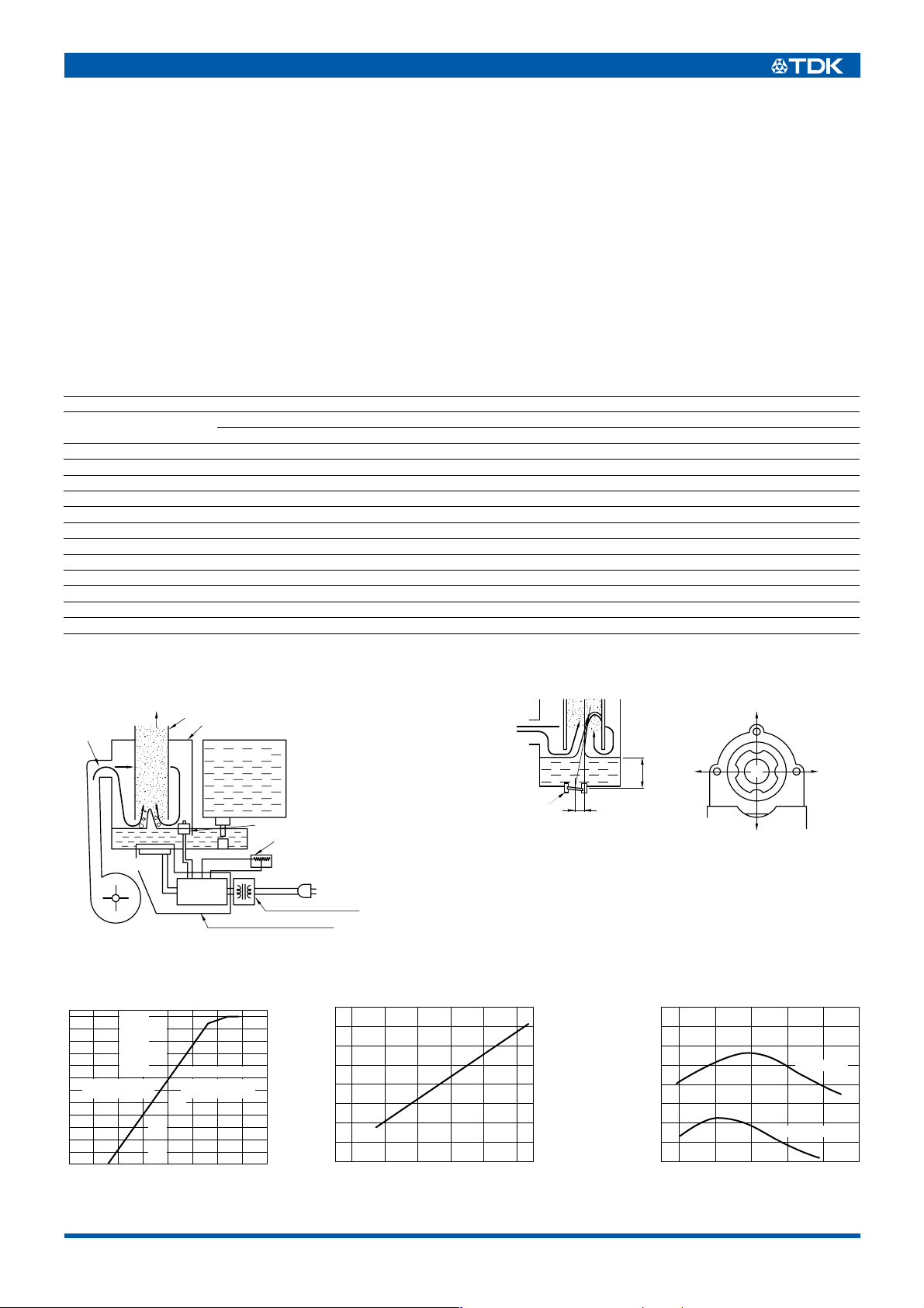
EXAMPLE OF ATOMIZATION CHAMBER CONSTRUCTION TYPICAL TRANSDUCER INSTALLATION
Various tilt directions of the transducer
2
35 to 45mm
0
(H means horizontal)
The arrows indicate the directions
of the various water jets.
Air-flow
Mist
Transducer
Fan moter
Mist discharge tube
Atomization chamber
Water tank
Float switch
Drive
circuit
Ultrasonic humidifier unit
External potentiometer
for control of mist generation
Power transformer
Transducer
(tilted about 7˚)
13mm
–3
31
TYPICAL CHARACTERISTICS OF HUMIDIFIER UNITS
VOLTAGE CHARACTERISTICS(48V) WATER TEMPERATURE CHARACTERISTICS(48V) WATER LEVEL CHARACTERISTICS
)]
+40
ml/hr
–30
(
33.6V
Mist generation
–20
(
)
)
38.4V
ratio(%)
–10
(
43.2V
(
0%=550
[
+20
–40
–60
)
48V+10
–20
Input voltage ratio(%
+20
)
(
57.6V
)
(
+30
62.4V
(
52.8V
)
)
700
ml/hr
(
)
600
500
Mist output
10 20 30 40 50
Water temperature(˚C
)
)
600
ml/hr
(
400
200
Mist output
30 35 40 45 50
Water level(mm
48V series
24, 12V series
)
• All specifications are subject to change without notice.
002-01 / 20080731 / ef441_nb.fm
Page 2
(2/4)
NB-514S TYPE
FEATURES
• Small size facilitates integration into various devices.
• Complies with noise regulations in the Radio Law.
• Reduces harmonic component noise.
• Parallel connection to one transformer is supported.
• Provides DC.48V output (maximum 30mA, smoothing filter not
included).
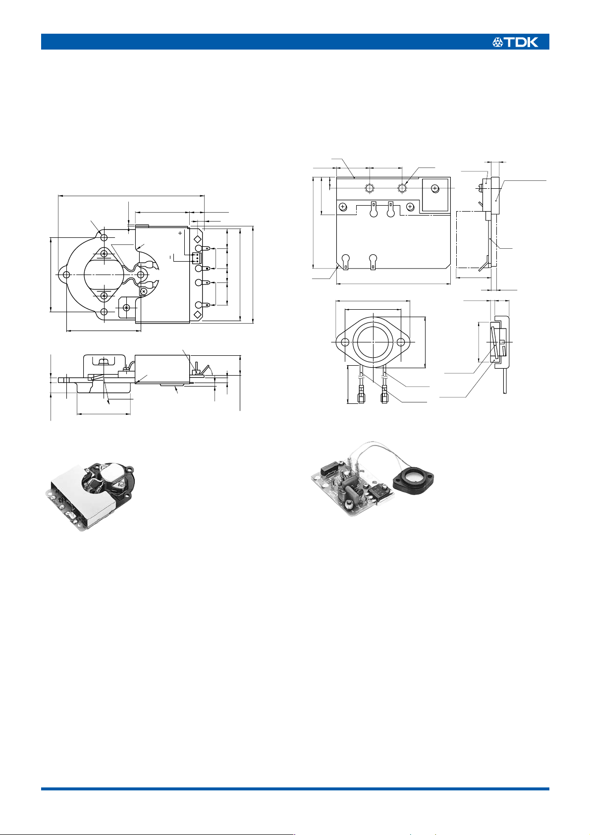
SHAPES AND DIMENSIONS
109±1
56± 0.2
7.5± 0.5 16.5
4-ø4.5± 0.3
56± 0.2
ø39.2± 0.2
AWG24
2max.
41
2-R2
ORG
YEL
Terminal block B3P-SHF-1AA
(
manufactured by Japan Solderless
Terminal Co., Ltd.
R1
Water cone
direction
Marking
or label
10±1
5
DC.48
F.T
V.R.
AC.48V
)
60˚
1.5
Dimensions in mm
15141117
3
71
73.5
16.5max.
NB-59S-09S TYPE
FEATURES
• Compact, with highly reliable circuitry.
• Separate transducer and drive circuit sections provide superior
layout versatility.
SHAPES AND DIMENSIONS
1C
24±0.2 2-ø4.520±0.2
22±0.5
7±0.2
54±1
(
)
2-C3
42±0.5
32± 0.2
100±10
68
Yellow
AWG-24
Orange
AWG-24
30±0.5
Transducer
Supporting
rubber
Transistor
20max.
4.5max. 9
Driver
circuit
area
ø24±0.4
Dimensions in mm
Tolerance: ±1
5
Aluminum base
PCB
3max.
• All specifications are subject to change without notice.
002-01 / 20080731 / ef441_nb.fm
Page 3

(3/4)
NB-80E-01 TYPE
FEATURES
• Compact, with highly reliable circuitry.
• Separate transducer and drive circuit sections provide superior
layout versatility.
• Because the ultrasonic frequencies used are higher than with
typical household-type units, mist particle size is extremely fine.
This part is thus ideal for products intended for smaller spaces.
SHAPES AND DIMENSIONS
43.5m ax.
32±0.2
ø24±0.4
ø18±0.3
2-ø3.5
31.5max.
18max.
40±0.2
20.75 ±0.2
63C
NB-80E-01
TYPE
NO.
Connector for VR(3 poles)
3022-03A
Housing
5224-03CHPB
Maker: Molex
53±0.2
65max.
32.5 ±0.2
21max.
Connector for power supply(2 poles)
3022-02A
5224-02CHPB
2-R15.6
26max.
1±0.2
5max.
120 ±15
TU-51X-H
4123
4.5max.
9.5max.
2-ø4.5±0.2
2-R5.5
Dimensions in mm
MOUNTINGS (Reference)
1.NB-514S TYPE
O-type
ring
Chamber
base
∗
7.5
11.5
9
Transducer
∗
7 for NB-58S
ø39.2± 0.2
29max.
Dimensions in mm
• A 39.2mm diameter hole is formed in the bottom of the water
chamber, which is connected using an O-type ring.
Water level is determined relative to the center of the transducer.
Screw holes are provided at four locations (refer to the technical
materials) for mounting.
Note: A strong O-type ring should be used for long-term use.
2.NB59S, NB-80E TYPES
ø24
ø18
Tank base
A
Rubber packing
Plastic case
(Metal case)
Screw:M4
×15
Dimensions in mm
The transducer can beak off if the A dimension depth is shallow.
TDK recommends a 2mm A-dimension depth and a screw tightening torque of 0.6N • m.
3.CONSTRUCTION OF NB59S
The drawing below shows an example method for transistor heat
dissipation. The attached aluminum cooling fins should fixed using
silicon rubber to a metallic water tank, etc. with sufficient head dissipation capacity.
(It is recommended to use a plastic water tank. However, if a
metallic water tank is absolutely must be used, be sure to insulate
it from the power supply line.)
P.C. boardMetal tank
Transducer unit
Silicon rubber
Aluminum radiation board
• All specifications are subject to change without notice.
002-01 / 20080731 / ef441_nb.fm
Page 4

PRECAUTIONS
• These units are readily damaged by operation when empty
(without water). Therefore a means (float switch, etc.) should be
provided to assure operation does not occur when empty.
• Contact TDK prior to use of this unit for applications utilizing
liquids other than water.
• The unit should be used only after sufficient consideration of the
product specifications for that specific unit.
• When using units in parallel, make sure that voltage differences
do not occur between the individual transducers.
• Do not use the unit to atomize a liquid other than drinking water.
Doing so can deteriorate the transducer.
• Do not operate the transducer when the atomization unit tank is
not charged with drinking water.
• Drain water from the transducer and clean the equipment into
which the unit is incorporated if not used for a long period of
time.
• Clean the transducer periodically to prevent any degradation in
the atomizing capacity due to buildup in the transducer of such
substances as calcium, sodium, magnesium, and silicon,
commonly found in drinking water.
• TDK is not responsible for damage to the transducer resulting
from use of oscillator circuitry not supplied or not approved by
TDK.
• TDK is not responsible for worsening of unit performance
resulting from operation in environments other than those
recommended, storage in environments other than those
recommended, or use of the unit in configurations other than
those recommended by TDK for efficient mist generation.
• TDK is not responsible for the vaporization of pathogenic
bacteria or particles, not responsible if drinking water contains
substances that impede vaporization, and not responsible for
bacterial growth due to lack of a water purification function.
• Please select a plastic material of construction for the water tank
design. Metallic construction can result in electrolytic corrosion
between the chamber base and water tank.
Furthermore, if multiple units are used with the same tank, and if
each unit is equipped to be separately turned ON/OFF, the
power supply terminal for each unit should use a double-pole
switch.
(4/4)
• All specifications are subject to change without notice.
002-01 / 20080731 / ef441_nb.fm
 Loading...