

Page 1
(1/4)
Chip Beads(SMD)
For Signal Line
MMZ Series MMZ2012 Type
FEATURES
• Chip bead(impeder), MMZ series offers 4 construction materials.
• Size standardized for use by automatic assembly equipment.
No preferred orientation.
• Either flow or reflow soldering methods can be used due to
electroplating of the terminal electrodes.
• High reliability due to an entirely monolithic structure.
• Closed magnetic circuit structure allows high-density installation
while preventing crosstalk between circuits.
• Low DC resistance structure of electrode prevents wasteful
electric power consumption.
• The products contain no lead and also support lead-free
soldering.
• It is a product conforming to RoHS directive.
APPLICATIONS
Personal computers, CRTs, liquid crystal display panels, printers,
hard disk drives, game machines, cellular phones, etc.
PRODUCT IDENTIFICATION
MMZ 2012 R 121 A T
(1) (2) (3) (4) (5) (6)
(1) Series name
(2) Dimensions L× W
(3) Material code
(4) Nominal impedance
121:120Ω at 100MHz
(5) Characteristic type
(6) Packaging style
T:Taping
Conformity to RoHS Directive
MATERIAL CHARACTERISTICS
R material: For wide frequency applications calling for broad
impedance characteristics.
For digital signal line applications calling requiring
good waveform integrity. Impedance values selected
for effectiveness at 10 to 200MHz.
S material: Standard type that features impedance characteristics
similar to those of a typical ferrite core.
For signal line applications in which the blocking region
is near 100MHz. Impedance values selected for effectiveness at 40 to 300MHz.
Y material: High frequency range type intended for the 100MHz
region and above.
For signal line applications in which the signal frequency is far from the cutoff frequency. Impedance values selected for effectiveness at 80 to 400MHz.
D material: For applications calling for low insertion loss at low fre-
quencies and sharply increasing impedance at high
frequencies. Designed for high impedance at high frequencies (200 to 500MHz) for signal line applications.
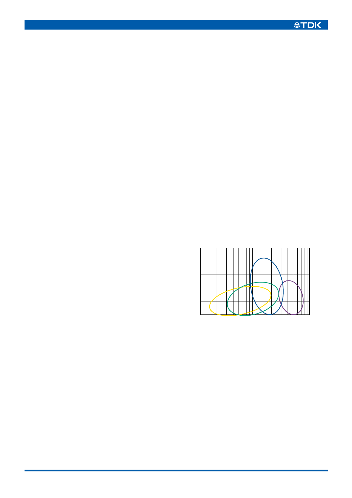
TYPICAL MATERIAL CHARACTERISTICS
2500
2000
)
Ω
(
1500
1000
Impedance
500
S
R
Y
D
HANDLING AND PRECAUTIONS
• Before soldering, be sure to preheat components. The preheat-
0
10 100 1000
Frequency(MHz)
ing temperature should be set so that the temperature difference
between the solder temperature and product temperature does
not exceed 150°C.
• After mounting components onto the printed circuit board, do not
apply stress through board bending or mishandling.
• Do not expose the inductors to stray magnetic fields.
• Avoid static electricity discharge during handling.
• When hand soldering, apply the soldering iron to the printed cir-
cuit board only. Temperature of the iron tip should not exceed
350°C. Soldering time should not exceed 3 seconds.
• Conformity to RoHS Directive: This means that, in conformity with EU Directive 2002/95/EC, lead, cadmium, mercury, hexavalent chromium, and specific
bromine-based flame retardants, PBB and PBDE, have not been used, except for exempted applications.
• Please contact our Sales office when your application are considered the following:
The device’s failure or malfunction may directly endanger human life (e.g. application for automobile/aircraft/medical/nuclear power devices, etc.)
• All specifications are subject to change without notice.
006-02 / 20080408 / e9412_mmz2012.fm
Page 2

(2/4)
SHAPES AND DIMENSIONS/RECOMMENDED PC BOARD
PAT TE RN
2+0.3, –0.1
1.25± 0.20.85± 0.2
0.5± 0.3
10.8 0.8
1.2
Weight: 8mg
Dimensions in mm
TEMPERATURE RANGES
Operating/storage –55 to +125°C
PACKAGING STYLE AND QUANTITIES
Packaging style Quantity
Taping 4000 pieces/reel
RECOMMENDED SOLDERING CONDITION
REFLOW SOLDERING
10s max.
250 to 260˚C
230˚C
180˚C
150˚C
Preheating
60 to 120s
Soldering
30 to 60s
Natural
cooling
ELECTRICAL CHARACTERISTICS
Par t N o.
(Ω)±25%
[100MHz]
MMZ2012R150A 15 0.05 1500
MMZ2012R300A 30 0.05 1500
MMZ2012R600A 60 0.1 1000
MMZ2012R121A 120 0.12 800
MMZ2012R301A 300 0.15 600
MMZ2012R601A 600 0.2 500
MMZ2012R102A 1000 0.3 500
MMZ2012S400A 40 0.1 1000
MMZ2012S800A 80 0.1 800
MMZ2012S121A 120 0.15 800
MMZ2012S181A 180 0.15 600
MMZ2012S301A 300 0.2 600
MMZ2012S601A 600 0.3 500
MMZ2012S102A 1000 0.35 500
MMZ2012Y150B 15 0.05 1500
MMZ2012Y300B 30 0.05 1500
MMZ2012Y600B 60 0.1 1000
MMZ2012Y121B 120 0.12 800
MMZ2012Y301B 300 0.15 600
MMZ2012Y601B 600 0.2 500
MMZ2012Y102B 1000 0.3 500
MMZ2012Y152B 1500 0.4 500
MMZ2012Y202B 2000 0.5 400
MMZ2012D800B 80 0.3 500
MMZ2012D121B 120 0.3 500
MMZ2012D301B 300 0.5 400
Impedance
∗
Test equipment: E4991A or equivalent
Test tool: 16192A or equivalent
Test temperature: 25±10°C
∗
DC resistance
(Ω)max.
Rated current
(mA)max.
Time(s)
TYPICAL ELECTRICAL CHARACTERISTICS
Z, X, R vs. FREQUENCY CHARACTERISTICS
MMZ2012R150A MMZ2012R300A MMZ2012R600A
120
100
)
80
Ω
(
60
40
Impedance
20
0
1 10 100 1000 10000
Z
R
X
Frequency(MHz
)
120
100
)
80
Ω
(
60
40
Impedance
20
0
1 10 100 1000 10000
Z
R
X
Frequency(MHz
)
120
100
)
80
Ω
(
60
40
Impedance
20
0
1 10 100 1000 10000
MMZ2012R121A MMZ2012R301A MMZ2012R601A
500
400
)
Ω
(
300
200
Impedance
100
0
1 10 100 1000 10000
Z
R
X
Frequency(MHz
)
500
400
)
Ω
(
300
200
Impedance
100
0
1 10 100 1000 10000
Z
R
X
Frequency(MHz
)
1000
900
800
)
700
Ω
(
600
500
400
Impedance
300
200
100
0
1 10 100 1000 10000
Z
R
X
Frequency(MHz
Z
R
X
Frequency(MHz
)
)
• All specifications are subject to change without notice.
006-02 / 20080408 / e9412_mmz2012.fm
Page 3

TYPICAL ELECTRICAL CHARACTERISTICS
Z, X, R vs. FREQUENCY CHARACTERISTICS
MMZ2012R102A MMZ2012S400A MMZ2012S800A
1600
1400
1200
)
Ω
(
1000
800
600
Impedance
400
200
0
1 10 100 1000 10000
Z
R
X
Frequency(MHz
)
300
250
)
200
Ω
(
150
100
Impedance
50
0
1 10 100 1000 10000
Z
R
Frequency(MHz
X
)
300
250
)
200
Ω
(
150
100
Impedance
50
0
1 10 100 1000 10000
MMZ2012S121A MMZ2012S181A MMZ2012S301A
300
250
)
200
Ω
(
150
100
Impedance
50
0
1 10 100 1000 10000
Z
R
X
Frequency(MHz
)
1000
900
800
)
700
Ω
(
600
500
400
Impedance
300
200
100
0
1 10 100 1000 10000
Z
R
X
Frequency(MHz
)
1000
900
800
)
700
Ω
(
600
500
400
Impedance
300
200
100
0
1 10 100 1000 10000
Z
R
X
Frequency(MHz
Z
R
X
Frequency(MHz
(3/4)
)
)
MMZ2012S601A MMZ2012S102A MMZ2012Y150B
1000
900
800
)
700
Ω
(
600
500
400
Impedance
300
200
100
0
1 10 100 1000 10000
Z
R
X
Frequency(MHz
)
1600
1400
1200
)
Ω
(
1000
800
600
Impedance
400
200
0
1 10 100 1000 10000
Z
R
X
Frequency(MHz
)
120
100
)
80
Ω
(
60
40
Impedance
20
0
1 10 100 1000 10000
MMZ2012Y300B MMZ2012Y600B MMZ2012Y121B
120
100
)
80
Ω
(
60
40
Impedance
20
0
1 10 100 1000 10000
Z
R
Frequency(MHz
X
)
120
100
)
80
Ω
(
60
40
Impedance
20
0
1 10 100 1000 10000
Z
R
Frequency(MHz
X
)
800
700
600
)
Ω
(
500
400
300
Impedance
200
100
0
1 10 100 1000 10000
Z
Frequency(MHz
Z
R
Frequency(MHz
R
X
)
X
)
• All specifications are subject to change without notice.
006-02 / 20080408 / e9412_mmz2012.fm
Page 4

TYPICAL ELECTRICAL CHARACTERISTICS
Z, X, R vs. FREQUENCY CHARACTERISTICS
MMZ2012Y301B MMZ2012Y601B MMZ2012Y102B
800
700
600
)
Ω
(
500
400
300
Impedance
200
100
0
1 10 100 1000 10000
Z
R
X
Frequency(MHz
)
800
700
600
)
Ω
(
500
400
300
Impedance
200
100
0
1 10 100 1000 10000
Z
R
X
Frequency(MHz
)
1600
1400
1200
)
Ω
(
1000
800
600
Impedance
400
200
0
1 10 100 1000 10000
MMZ2012Y152B MMZ2012Y202B MMZ2012D800B
1600
1400
1200
)
Ω
(
1000
800
600
Impedance
400
200
0
1 10 100 1000 10000
Z
R
X
Frequency(MHz
)
2600
2400
2200
2000
)
1800
Ω
(
1600
1400
1200
1000
800
Impedance
600
400
200
0
1 10 100 1000 10000
Z
R
X
Frequency(MHz
)
1000
900
800
)
700
Ω
(
600
500
400
Impedance
300
200
100
0
1 10 100 1000 10000
Z
R
X
Frequency(MHz
Z
Frequency(MHz
(4/4)
)
R
X
)
MMZ2012D121B MMZ2012D301B
1600
1400
1200
)
Ω
(
1000
800
600
Impedance
400
200
0
1 10 100 1000 10000
Frequency(MHz
Z
X
)
R
4000
3500
3000
)
Ω
(
2500
2000
1500
Impedance
1000
500
0
1 10 100 1000 10000
Frequency(MHz
Z
)
R
X
PACKAGING STYLES
REEL DIMENSIONS TAPE DIMENSIONS
1.0
ø60±2.0
1.1max. 4.0±0.1 4.0±0.1
Sprocket hole
1.5±0.2
1.5
+0.1
–0.0
2.0±0.05
Cavity
2.3±0.2
1.75±0.1
3.5±0.05
8.0±0.3
2.0±0.5
ø13±0.5
ø21±0.8
ø178±2.0
9.0±0.3
13.0±1.4
Dimensions in mm
• All specifications are subject to change without notice.
160min. Taping 200min.
Drawing direction
006-02 / 20080408 / e9412_mmz2012.fm
300min.
Dimensions in mm
 Loading...