

Page 1

Digalox DPM72-AV Instruction manual (Rev-2018-09)
Package contents: Panel meter Digalox DPM72, 5 × jumpers, 1 × mounting bracket
1. Intended use
Indoor use non condensing, non corrosive.
Panel mounting.
Failure to comply with these instructions will void all guarantee and warranty.
2. Safety instructions
Note: The measurement inputs of the device can carry life-threatening
voltages!
When working on the device hazardous voltages must not be connected to
the device!
The device must not be used as the only protective device or protective
shutdown.
Read instruction manual carefully before operating the device!
The device is not intended to protect persons or facilities against harm. Specific
devices must be used to guarantee safety (protection relays, cut-off switches,
etc.).
When connecting switches to the terminals J1-J6, only switches must be used
whose isolation voltage is at least twice the maximum occurring measurement
voltage. For example, when measuring 250 V AC switches must be isolated for
at least 500 V.
Do not open the housing!
Do not use the instrument in the presence of explosive or flammable substances!
All cables carrying hazardous voltages must be secured with external separators.
----- 1 -----
Page 2
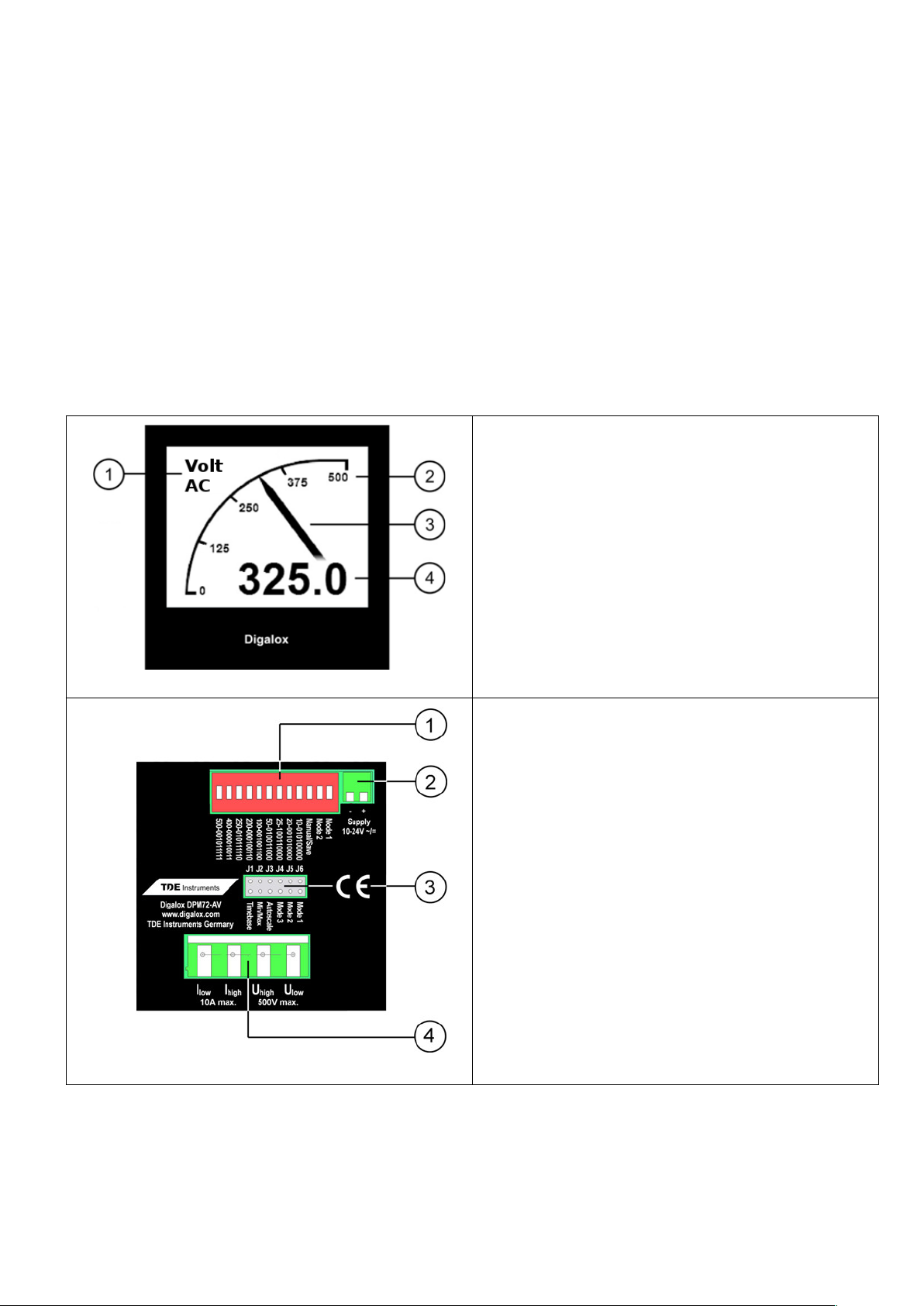
3. Description
The measurement modes volt AC/DC, ampere AC/DC, frequency and 5 A current
transformer are supported. Scale endpoint of the indicator as well as scaling of the
analogue signal and current transformer measurement can be adjusted freely via the
DIP switch, alternatively the option for automatic adaption of the scale endpoint can
be used. The unit can be switched between volt and ampere measurement via an
external switch. Minimum and maximum values are recorded and can be displayed
optionally using an external switch. Measured values are recorded over a time span
of 3 minutes up to 14 days. The time base as well as the display of the measuring
history can be activated by an external switch. The measured values remain stored
as long as the device is supplied with voltage.
Front
1 Measure mode text
2 Upper scale caption
3 Graphical measurement display
4 Digital measurement value
Back
1 DIP switch for setting
measurement mode and upper
scale caption
2 Supply voltage input
3 Jumpers for configuration or
connection external switch for
activating/switching
measurement mode, graphical
historic data display, min/max
display, auto-scaling
4 Measurement inputs
----- 2 -----
Page 3
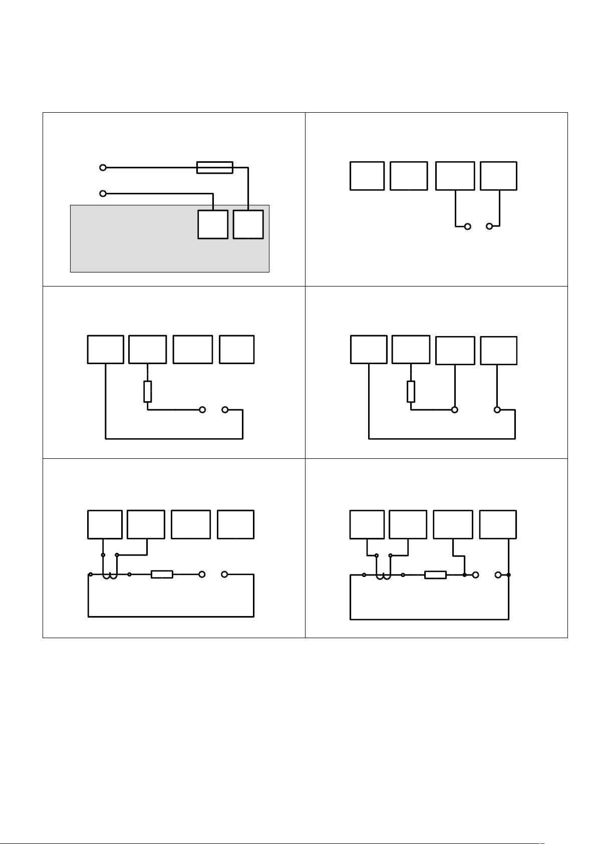
4. Electrical Connections
The device may only be operated in one of the connection options shown below.
Supply
Digalox
−
+
10 - 24 V Fuse 250 mA
Supply
Voltage direct
+/L -/N
max.
500 V
I
low
I
high
U
high
U
low
Current direct
I
low
I
high
U
high
U
low
Load
+/L -/N
max.
10 A
Current and voltage direct
I
low
I
high
Load
+/L
-/N
max.
10 A
max.
500 V
U
high
U
low
Current via current transformer
Load
+/L -/N
Current
Transformer
I
low
I
high
U
high
U
low
Current via current transformer,
voltage direct
Load
+/L -/N
Current
Transformer
max.
500 V
I
low
I
high
U
high
U
low
----- 3 -----
Page 4

5. Configuration
The device can be configured via DIP switches and jumpers.
Scaling
In modes where a scaling is necessary to represent the correct measurement value
(for example 5 A AC for current transformer) the upper scale value corresponds to
the primary value of the current transformer.
Example: upper scale value = 50 = primary value of the current transformer
Configuration via DIP switches and jumpers if only one measurement mode is
required (Manual mode)
1. Set DIP switch 10 to ON position.
2. Set measurement mode with jumpers at J4-J6 according to table "Measurement
mode”, column “Manual mode".
3. Set upper scale caption for the first measurement mode with DIP switches 1-9
(see “Configuration of the upper scale caption”).
4. Connect supply voltage.
Configuration via DIP switches and jumpers if it is required to switch between
multiple measurement modes via an external switch (Save mode)
The required measurement modes are configured and saved sequentially.
1. Connect supply voltage.
2. Set DIP-switch 10, 11 and 12 to OFF position.
3. Set the measurement mode with jumpers at J4-J6 according to table
"Measurement mode”, column “Save mode".
4. Set DIP switch 10 to ON position.
5. Set upper scale caption for the first measurement mode with DIP switches 1-9
(see “Configuration of the upper scale caption”).
6. Set time base for graphical historic data display (optional, see “Other settings”).
7. Set DIP switch 10 to OFF position.
8. "Saved” appears on the display. The configuration of the first measurement
mode is now completed.
9. When using multiple measurement modes repeat steps 2-8 until all required
measurement modes are configured. The time base does not need to be set
again, as it is used for all measurement modes.
10. In operation the measurement modes can be changed with a switch at J4-J6
according to table "Measurement mode”, column “Save mode".
----- 4 -----
Page 5

Configuration of the upper scale caption
The upper scale caption is binary coded using DIP switches 1-9. Possible values are
1 to 500. Switch 1 corresponds to 256, switch 2 corresponds to 128, switch 3
corresponds to 64, etc., switch 9 corresponds to 1. For configuration, proceed as
follows:
1. Connect supply voltage.
2. Set DIP switches 1-9 to OFF position.
3. Set DIP switch 10 to ON position.
4. Start with 1st switch.
5. Set switch to ON position.
6. If the displayed value is greater than the desired value, set the switch back to
OFF position.
7. If the displayed value is less than the desired value, leave the switch in ON
position and move on to the next switch.
8. Repeat steps 5 to 7 until the desired value is displayed.
----- 5 -----
Page 6
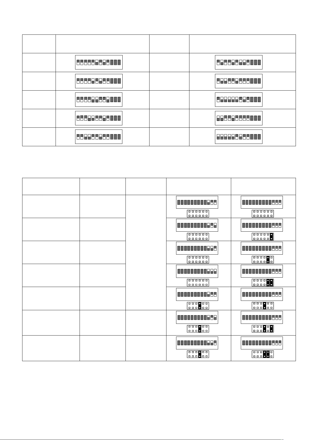
Table common switch combinations
Value Combination
(DIP switch 1-9)
Value Combination
(DIP switch 1-9)
10
ON
1 2 3 4 5 6 7 8 9
10 11 12
150
ON
1 2 3 4 5 6 7 8 9
10 11 12
20
ON
1 2 3 4 5 6 7 8 9
10 11 12
200
ON
1 2 3 4 5 6 7 8 9
10 11 12
25
ON
1 2 3 4 5 6 7 8 9
10 11 12
250
ON
1 2 3 4 5 6 7 8 9
10 11 12
50
ON
1 2 3 4 5 6 7 8 9
10 11 12
400
ON
1 2 3 4 5 6 7 8 9
10 11 12
100
ON
1 2 3 4 5 6 7 8 9
10 11 12
500
ON
1 2 3 4 5 6 7 8 9
10 11 12
Table measurement mode
Measurement
mode
Display Scale Manual mode Save mode
V AC direct Volt
AC
ON
1 2 3 4 5 6 7 8 9
10 11 12
J1 J6
ON
1 2 3 4 5 6 7 8 9
10 11 12
J1 J6
A AC direct Ampere
AC
ON
1 2 3 4 5 6 7 8 9
10 11 12
J1 J6
ON
1 2 3 4 5 6 7 8 9
10 11 12
J1 J6
V DC direct Volt
DC
ON
1 2 3 4 5 6 7 8 9
10 11 12
J1 J6
ON
1 2 3 4 5 6 7 8 9
10 11 12
J1 J6
A DC direct Ampere
DC
ON
1 2 3 4 5 6 7 8 9
10 11 12
J1 J6
ON
1 2 3 4 5 6 7 8 9
10 11 12
J1 J6
AC Frequency Freq.
Hz
ON
1 2 3 4 5 6 7 8 9
10 11 12
J1 J6
ON
1 2 3 4 5 6 7 8 9
10 11 12
J1 J6
5 A AC scaled
(Current
transformer)
Ampere
CT
Upper
scale
caption
ON
1 2 3 4 5 6 7 8 9
10 11 12
J1 J6
ON
1 2 3 4 5 6 7 8 9
10 11 12
J1 J6
1 A AC scaled
(Current
transformer)
Ampere
CT
Upper
scale
caption
ON
1 2 3 4 5 6 7 8 9
10 11 12
J1 J6
ON
1 2 3 4 5 6 7 8 9
10 11 12
J1 J6
----- 6 -----
Page 7
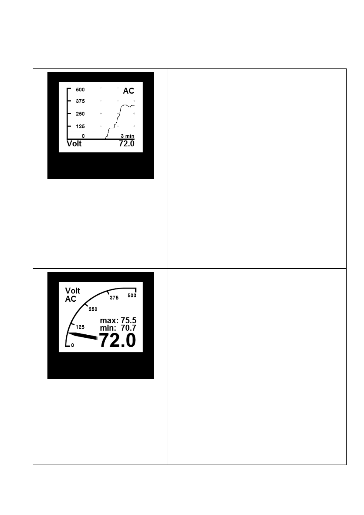
6. Other settings
The following functions can be activated independently by short-circuiting
connectors J1-J3 by jumper or switch during operation:
J1: Graphical historic data display
To activate the graphical historic data
display connector J1 is shorted. The unit
displays the stored values within the set
time base as a graphical trend.
The time base can be set to days (7, 14),
hours (6, 12, 24, 48, 72) or minutes (3, 15,
30, 60).
The time base can be changed by
alternately opening and closing J1
(interval < 2 sec). When first opening and
closing J1 the current time base is
displayed. For each subsequent opening
and closing the time base changes to the
next setting. In order to save the setting
permanently, DIP switch 10 must be
switched from ON to OFF position.
J2: Min-Max-display
To activate the Min-Max display connector
J2 is shorted. The display shows the
maximum and minimum values recorded
since the last reset. The values can be
reset by opening and closing connection
J2 shortly (interval < 2 sec). The display
shows "Minmax reset".
J3: Auto scaling
To activate auto-scaling J3 connector is
shorted. The device automatically
changes the upper scale caption
depending on the current measuring value
between 10, 100 and the set upper scale
caption.
----- 7 -----
Page 8
7. Mounting
Carefully insert the instrument into the panel cut-out. Insert the mounting bracket
from the back and push towards the panel until the instrument sits tight. Make sure
the mounting bracket is snapped into the side of the housing. To ensure IP65
protection (dust and water jet) when mounting in a front panel, use optional gasket
(separately available).
8. Specifications
DPM72AV
Supply 10 - 24 V AC/DC
Display LCD graphic display 192 × 160 pixels
Measuring range voltage ±500 V AC/DC
Accuracy voltage ±1 % true RMS
Internal resistance voltage 2.6 MΩ
Measuring range ampere ± 10 A AC/DC and 5 A AC for current transformer
Accuracy ampere ±1 % true RMS
Internal resistance ampere 5 mΩ
Measuring range frequency 10 - 500 Hz
Accuracy frequency ±0.1 Hz
Recording of measurement 3 min to 14 days
Operating temperature 0 °C to +50 °C
Storage temperature -20 °C to +70 °C
Front panel 72 mm × 72 mm
Panel cut-out 68 mm × 68 mm
Protection front IP65 from the front
9. Cleaning
Observe the safety instructions before cleaning the instrument. Clean the
instrument with a dry lint-free soft cloth. Do not use solvents.
10. Contact Information
TDE Instruments GmbH, Gewerbestraße 8, D-71144 Steinenbronn
Phone: +49 7157-20801
E-Mail: [email protected]
Internet: www.tde-instruments.de, www.digalox.com
----- 8 -----
 Loading...