

TDE Instruments Digalox DPM72-MPN Instruction Manual

Digalox DPM72-MPN
Instruction manual
Visit www.digalox.com
to download
Package contents:
Panel meter Digalox DPM72,
1. Intended Use
• Indoor use non
condensing
• Panel mounting.
•
Failure to comply with these instructions will
•
Preferred supply of USB devices via scre
Supply via USB in operation, USB supply voltage must be at least 5V.
2. Safety instructions
•
Note: the measurement inputs of the device can carry life
voltages!
• When working on the
device
the device!
•
The device must not be used as the only protective device or protective
shutdown.
• Read
instruction manual
•
The device is not intended to protect persons or facilities against harm. Specific
devices must be used to guarantee safety (prote
• When
connecting switches
whose isolation voltage
voltage. For example,
when measuring
least 500V.
• Do not open the
housing!
• Do not use
the instrument
• All cables
carrying hazardous
separators.
----- 1 -----
(Rev-2018-03)
software “Digalox
Manager”
5x jumpers, 1
x
, non corrosive.
void
all guarantee and warranty.
w terminals with 10 to
hazardous voltages must not be connected
carefully before operating the device!
ction relais, off
to the terminals J1-J6 only
switches must
is at least twice the
maximum occurring
250V AC switch
must be isolated
in the presence of explosive or
flammable substances!
voltages
must be secured
.
mounting bracket
24V AC/DC.
-threatening
to
-switches, etc).
be used
measurement
for at
with external
----- 2 -----
3. Description
The multi display with RGB backlight is able to display up to 4 parameters
simultaneously. Thresholds can be associated with individual warning backlight
colors. The unit can be switched between measurement modes via an external
switch. Minimum and maximum values for each parameter are recorded and can
be displayed optionally using an external switch. Measured values of one
parameter are recorded over a time span of three minutes up to 14 days. The time
base as well as the display of the measuring history can be activated by an
external switch.
The following parameters can be adjusted using the USB-Software: Scale
endpoint, scale caption, display style (pointer, tachometer, bar graph, and more),
splash display, backlight color, thresholds for alarm output, threshold warning color
(light, blink), hysteresis, and more. Recorded measurement values can be read
and a continuous transmission up to four measuring values can be enabled. Using
the software, values can be viewed and exported as CSV file.
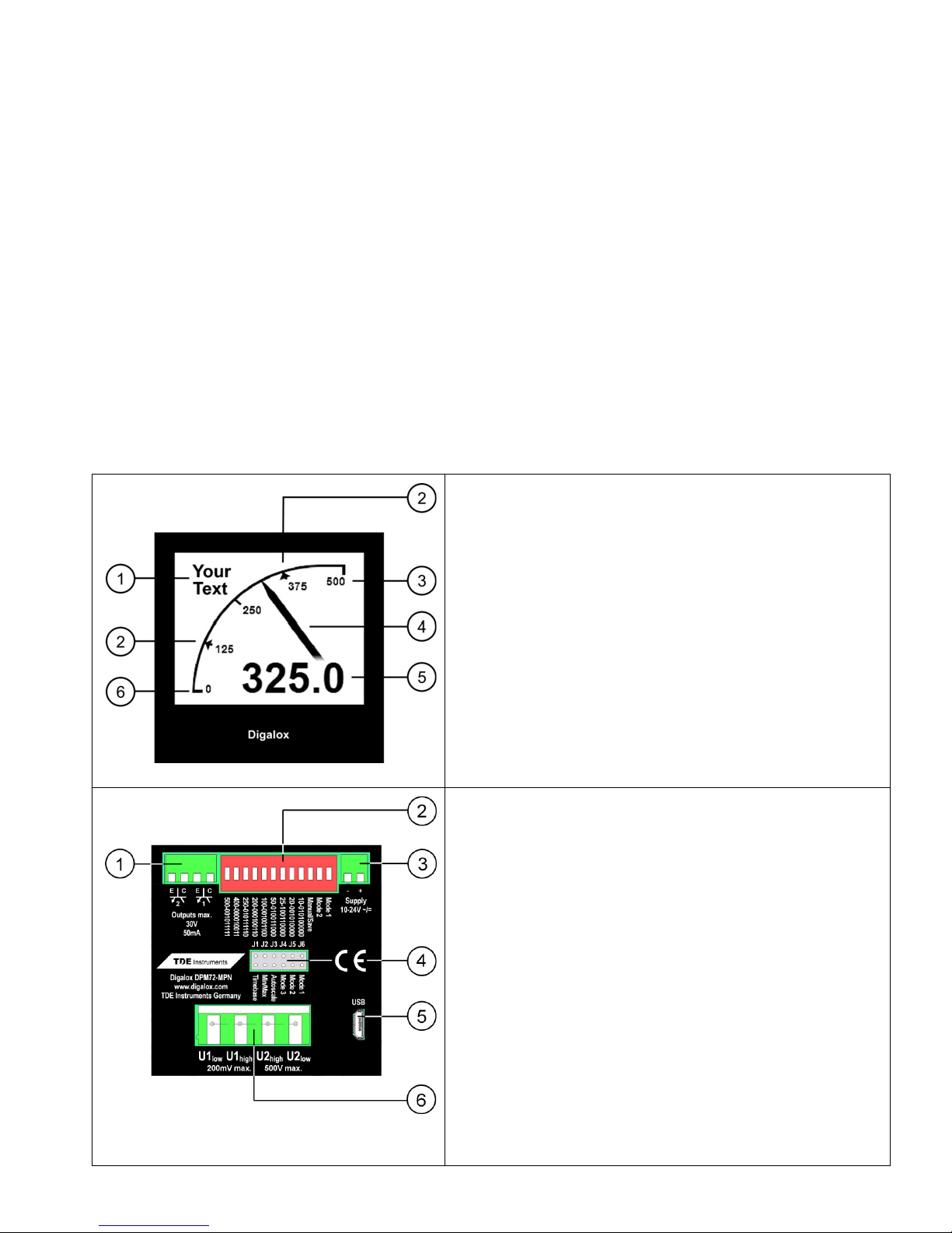
Front
1 Unit or free text
2 Threshold value
3 Upper scale caption
4 Graphical measurement display
5 Digital measurement value
6 Lower scale caption
Back
1 2 optocoupler switch outputs
2 DIP switch for setting measurement mode
and upper scale caption
3 Supply voltage input
4 Jumpers for configuration/connection
external switch for activating/switching
measurement mode, graphical historic
data display, min/max display, auto-
scaling
5 USB interface for alternative power supply
and software communication interface
6 Measurement inputs
----- 3 -----
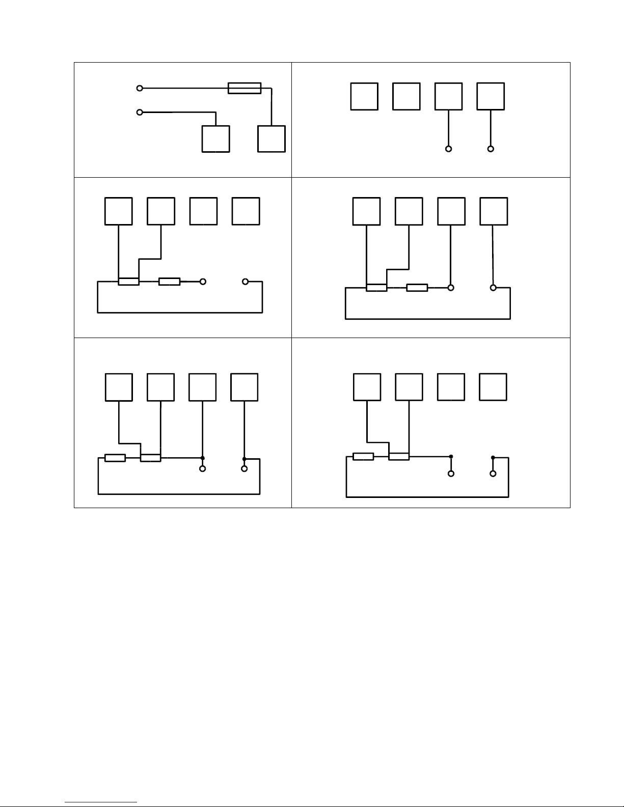
4. Electrical Connections
Supply
Voltage direct
Current via external shunt
Voltage direct, current via external shunt
Voltage, current via external
shunt on high side, 50V max!
Current via external shunt on high side,
50V max!
Warning:
The device may only be operated in one of the connection options shown
above!
Voltage measurement on the high side (between plus and load) is
recommended only for voltages up to 50V!
In this case the entire device is on high potential. Particularly to be considered
when connecting switches to JP1-6.
When measuring current, an external shunt must be connected to U1!
U
s
U
s
10-24V Fuse 250mA
Measurement inputs
U1
low
U1
high
U2
high
U2
low
-+
max.
500V
U1
low
U1
high
U2
high
Load
max.
200mV
U2
low
-
+
Shunt
max.
500V
U1
low
U1
high
U2
high
Load
max.
200mV
U2
low
-
+
Shunt
U1
low
U1
high
U2
high
Load
max.
200mV
U2
low
-+
Shunt
max.
50V!
U1
low
U1
high
U2
high
Load
max.
200mV
U2
low
-+
Shunt
max.
50V
 Loading...