

Page 1

User's Manual
Thank you for purchasing our product.
Carefully read this instruction manual
before using this unit.
© Copyright T&D Corporation. All rights reserved.
2010.08 16504450006 6th Edition
Page 2

i
■ Important Notices and Disclaimers
- In order to properly use this product, please carefully read this manual
before using.
- T&D Corporation accepts no responsibility for any malfunction of and/or
trouble with this product or with your computer that is caused by the
improper handling of this product and will deem such trouble or malfunction
as falling outside the conditions for free repair outlined in the attached
warranty.
- All rights of this User
’
s Manual belong to T&D Corporation.
It is prohibited to
use, duplicate and/or arrange a part or whole of this User
’
s Manual without
the permission of T&D Corporation.
- Microsoft and Windows are registered trademarks of Microsoft Corporation
in the United States and/or other countries.
- Windows Vista is either a registered trademark or trademark of Microsoft
Corporation in the United States and/or other countries.
- All registered trademarks, company names, product names and logos
mentioned herein are the property of T&D Corporation or of their respective
owners.
- Specifications, design and other contents outlined in this manual are subject
to change without notice.
- On-screen messages in this manual may vary slightly from the actual
messages.
- Please notify the shop where you purchased this product or T&D
Corporation of any mistakes, errors or unclear explanations in this manual.
-T&D Corporation accepts no responsibility for any damage or loss of income
caused by the use of our product.
- This product has been designed for private or industrial use only. It is not for
use in situations where strict safety precautions are necessary such as in
connection with medical equipment, whether directly or indirectly.
- We are not responsible for any malfunction or trouble caused by the use of
our product or by any problem caused by the use of measurement results of
our unit. Please be fully aware of this before using our product.
- This User
’
s Manual cannot be reissued, so please keep it in a safe place.
Page 3

ii
Software User Agreement
■ Disclaimers
- T&D Corporation does not guarantee the operation of T&D Recorder for
Windows
.
- T&D Corporation shall not accept any responsibility for any damage,
whether direct or indirect, that results from the usage of T&D Recorder for
Windows
.
- Specifications of T&D Recorder for Windows may be subject to change and
service may be terminated without advance notice to the user. In such a
case, T&D Corporation shall not be responsible for any damages, whether
direct or indirect, from the inability to use T&D Recorder for Windows
.
- T&D Corporation has no obligation to correct any defects found in T&D
Recorder for Windows
.
■ Copyright
- The Copyright for T&D Recorder for Windows, including the program and
relevant documents, belongs solely to T&D Corporation.
- The reprinting or redistribution for commercial purposes whether in part or
in whole, in magazines or as a part of any product is strictly forbidden
without the expressed consent of T&D Corporation. Any inquires concerning
commercial redistribution should be directed to the Sales Department of
T&D Corporation.
- Please do not attempt to make any changes or modifications to T&D
Recorder for Windows
.
Page 4

iii
Table of Contents
User's Manual ......................................................1
■ Important Notices and Disclaimers .................. i
Software User Agreement ........................ii
■ Disclaimers ..................................................... ii
■ Copyright ......................................................... ii
Using the Software with Windows 7 / Vista 1
■ Notes about graph operation ..........................1
■ About the Saving Location for Data Files ........1
Before Using… ........................................ 2
What is T&D Recorder for Windows
? ...... 3
■ Outline .............................................................3
■ Basic Functions ...............................................3
Basic Procedures .................................... 5
■
USB Communication for Windows 7 / Vista / 2000
..5
■ USB Communication for Windows XP ............6
■ Communication via RS-232C ........................7
Installing the Software ............................. 8
■ For Windows XP/2000 .................................... 9
■ For Windows 7/ Vista ...................................
10
Operating the Software .......................... 13
■ Opening the Software ................................... 13
■ Main Window .................................................13
■ Help ...............................................................
14
Forms of Communication: A Quick Look ................ 15
Communication between RTR-5 Series
Loggers and
Data Collectors
.......................................... 17
■ Wireless Communication .............................. 17
■ Optical Communication ................................. 18
Communication between Data Collector(s) and
Computers
............................................... 19
■ USB Communication (RTR-57U) ..................19
■ Serial Communication (RTR-57C/57U) .........20
Communication between RTR-5 Series Data Loggers
and Computers
.......................................... 21
Installing the USB Driver .......................
23
■ For Windows 7 / Vista / 2000 .......................23
■ For Windows XP ........................................... 25
If USB Device Driver Installation Fails ... 29
■ How to Re-install ........................................... 29
Setting Up the Communication Port ...... 31
■ Communication via USB ...............................31
■ Communication via RS-232C ........................32
Remote Unit Registration ...................... 33
■ Registering a Remote Unit ............................ 33
■ [Collect Registration Info] Button ...................35
■ [New Registration] Button ............................. 36
■ Confirming after Registration ........................
38
Other Remote Unit Registration Functions
39
■
Saving Registration Contents to File: [File] Menu
39
■ Saving as Text File: [File] Menu ....................39
■
[Set Number of Possible Registrations] Button ...
40
■ [Return to Original] Button ............................41
■ [Change/Delete] Button .................................41
■ [Transfer List Info] Button ..............................42
■ [View Remote Info] Button ............................43
RTR-51/52/52Pt: Start Recording .......... 44
■ Sensor Settings (RTR-52Pt) ........................ 47
RTR-51/52/52Pt: Downloading Recorded Data
48
RTR-51/52/52Pt: Value Adjustment Function
. 50
■ Temperature: 1-point Adjustment ..................50
■ Temperature: 2-point Adjustment ..................51
■ Adjustment Settings ......................................51
RTR-53 : Start Recording ...................... 53
RTR-53:
Downloading Recorded Data .. 56
RTR-53 : Value
Adjustment Function ..... 58
■ Temperature/Humidity:1-point / 2-point
Adjustment ........................................................58
■ Adjustment Settings ......................................58
RVR-52A: Start Recording ..................... 61
RVR-52A: Downloading Recorded Data ..
65
RVR-52A
: Value Adjustment Function .. 67
■ Voltage : 1-point / 2-point Adjustment ...........67
■ Adjustment Settings ......................................67
■ Moisture Probe Settings ................................69
RTR-57C/57U: Downloading Recorded Data
. 71
■ Collect RTR-57C/57U Data Info ....................71
■ Download Recorded Data ............................. 73
■ Downloading Several Sets of Data at One Time
75
■
About other Buttons .......................................77
Setting the RTR-57C/57U Clock ............ 78
RTR-57C/57U : Upper and Lower Limits
.. 79
Setting the Date Display Format ............ 81
Temperature
/Humidity Graph ................ 83
■ Display Names and Functions ...................... 83
Page 5

iv
■ Zooming In and Out on the Graph ................ 85
■ Data List Display ...........................................86
Editing the Graph: [View] Menu ............. 87
■
Changing graph display colors: From the [View] Menu
.87
■
Selected Channels ON/OFF: From the [View] Menu
.87
Editing the Graph: [Tools] Menu ............ 88
■
Setting High, Low, Average Calculation Range: From the
[Tools] Menu
.............................................................. 88
■
Editing Recording Conditions : From the [Tools] Menu
. 89
■
Re-ordering Channel Data: From the [Tools] Menu
90
■
Erasing Selected Channel Data:From the [Tools]
Menu
..................................................................91
■
Shifting Unit (℃ / ゜F): From the [Tools] Menu ..
91
■ Changing Graph Colors: From the [Tools] Menu
91
■ Copying Display to Clipboard:From the [Tools]
Menu ..................................................................92
■ Graph:From the [Graph] Menu ......................93
Multi-scale Graph .................................. 94
■ Display Names and Functions ...................... 95
■ Zooming In and Out on the Graph ................ 97
■ Data List Display ...........................................98
Editing the Graph ................................... 99
■
Selected Channels ON/OFF:From the [View] Menu
. 99
■ Scale Display ON/OFF: From the [View] Menu 99
■ Setting High, Low, Average Calculation Range:
From the [Tools] Menu ..................................... 100
■
Editing Recording Conditions:From the [Tools] Menu
101
■
Re-ordering Channel Data: From the [Tools] Menu
102
■
Merging Channel Data : From the [Tools] Menu
103
■
Erasing Selected Channel Data :From the [Tools] Menu
104
■
Vertical Axis Range Display Settings: From the [Tools] Menu
105
■
Scale and Unit Conversion: From the [Tools] Menu
106
■
Changing Graph Colors: From the [Tools] Menu
107
Event Viewer ........................................ 108
■ Display Names and Functions .................... 108
■
Shifting Display: From the [View] Menu or Toolbar
.110
■ Shifting Ascending/Descending: From the [View]
Menu or Toolbar ...............................................110
File Info ................................................ 111
Print Preview and Printing ...................
112
Saving a File ........................................
113
■ Temp/Humid Graph and Multi-scale Graph . 113
■ Event Viewer ...............................................114
Saving Data in Text File ....................... 115
■ Temp/Humid Graph and Multi-scale Graph .115
■ Event Viewer ...............................................116
Opening a File ..................................... 117
■ Opening a File with the Temp/Humid Graph and
Multi-scale Graph ............................................117
■ Opening a File with the Event Viewer .........118
How to Re-install ................................. 119
■ For Windows XP/2000 ................................ 119
■ For Windows 7/ Vista .................................120
Troubleshooting ................................... 121
Specification ........................................
127
Page 6

1
Using the Software with Windows 7 / Vista
■ Notes about graph operation
- Opening a Temp / Humidity Graph, Multi-scale Graph or other data file
(.trx, etc…) by dropping it into the Graph window
If you wish to open a file by dropping it into a Graph, it will not appear if the
Graph has been opened using [Run as Administrator]. Please open the
Graph as a general User. In general, we suggest when using Vista to only
use [Run as Administrator] to open the Graphs the first time in order to link
the type of data files (extension) to the Graph programs. After that please
open as a general user and carry out the opening of data as usual.
■ About the Saving Location for Data Files
The application automatically creates a new data file each time an AutoDownload session occurs. Note that when using the Vista OS the [Virtual
Store] function will redirect files from the default folder into which the program
was installed to separate folders under [Program Files] for each user, as
shown below: [C:\User\(AccountName)\AppData\Local\VirtualStore\Program
Files\(Application)].
( EX:
If login was carried out using the account name [myname] and [T&D Recorder
for Windows] is the application being run, the saving location will appear in the
application window as: [C:\Program Files\T&D Recorder for Windows\data] but
due to the [Virtual Store] function the actual saving location will be [C:\User\
myname\AppData\Local\VirtualStore\Program Files\
T&D Recorder (RTR-5)
US].
If the login was carried out from [Run as Administrator], the file will be saved
to the folder as it appears in the application window.
Page 7

2
Before Using…
Important Notes about the Installation Procedure (for using this
product with USB communication).
Thank you for choosing T&D Products.
In order to use a USB connection to communicate between this
product and a PC, it is necessary to install the application and the
USB driver.
Before connecting this product to a PC with a USB cable, it is
necessary to first install the application and the USB driver.
If you use the USB cable to connect the product to a PC before
installation, the USB driver may not properly install.
If you have connected the product to a PC without first installing the
driver, please make sure to press [Cancel] in the [Installation Wizard]
window when it pops up the PC screen and then disconnect the
USB cable from the product.
For details about how to use, see
[Basic Procedures] on P.5-7.
Page 8

3
What is T&D Recorder for Windows?
■ Outline
By using T&D Recorder for Windows, you can easily display the data
measured and recorded with the RTR-51/52/52Pt/53, RVR-52A via
our exclusive short-wave wireless technology in table or graph form
and control printing with your computer.
Upon opening T&D Recorder for Windows, a launcher window in
which icons are displayed will appear. By clicking an icon, the graph,
settings, and /or communication screen for that type of unit will be
displayed.
This software requires the following operating environment:
Compatible OS Microsoft Windows 7 32/64bit English
Microsoft Windows Vista 32bit English
Microsoft Windows Xp 32bit (SP2 or above)English
Microsoft Windows 2000 (SP3 or above) English
* For Windows 2000, XP ,Vista and 7, in order to install [T&D Recorder
for Windows], it is necessary to have Administrator rights (Computer
Administrator) for the computer in which you wish to install it.
PC/CPU IBM compatible equipped with more than Pentium 90MHz or NEC 98
Series with serial communication (RS-232C D-Sub 9 pin).
Memory More than 16MB memory capacity
Hard Disk More than 4MB of empty hard disc space
Monitor VGA (Above SVGA (800 × 600) is recommended)
More than 256 colors can be displayed
■ Basic Functions
● Group and Remote Unit Registration
If you wish to carry out wireless communication between an RTR-57C/57U
unit and RTR-51/52/52Pt/53, RVR-52A unit, it is necessary to first complete
via computer the Remote Unit Registration of the RTR-51/52/52Pt/53,
RVR-52A unit to the RTR-57C/57U. Remote Units can be operated and
managed in Groups.
● Display of Data List Collected in RTR-57C/57U
A list of all data collected at the time of downloading is displayed, from
which all or part of the data can be used to create files or graphs.
Page 9

4
● Mixed Use with Other Units
You can make graphs in which data from RTR-51/52/52Pt/53 and RVR-52A
units are mixed. If TR-5 / TR-7 Series data have been read into the
RTR-57C/57U unit, management of such mixed data is also possible.
● Temperature/Humidity Graph / Multi-Scale Graph
In Temperature/Humidity graphs, the graph or list of temperature and
humidity data is displayed. In Multi-scale Graphs, the graph or list of
voltage, pulse, temperature and humidity data is displayed. You can also
set the scale or units to match the type of downloaded data.
● Displaying 8 Channels of Data in One Graph
You can simultaneously display up to 8 channels of recorded data
downloaded from a main unit in one graph.
● Printing Graphs and Data Lists
You can print graphs displayed on screen in full color. When printing a data
list, the printing of every recording date is possible.
● Measured Data List Display
In the measured data list display, the highest, lowest, and average values
are shown in different colors.
● Event Viewer
In the Event Viewer, a data list showing the time of events is displayed.
● Print Preview and Printing
Select the data to be printed and after checking it in the preview window
you can proceed to print.
● Creating Text File
Recorded data can be saved in universal Text file format (such as CSV
Format) to be read and manipulated by all common spreadsheet software
such as Excel or Lotus.
Page 10

5
Basic Procedures
NOTE:
- To make sure that the USB driver is properly installed, please follow the correct
procedure as outlined here.
■ USB Communication for Windows 7 / Vista / 2000
RTR-57U
Installing the provided software
see P.9 -11
Please follow the directions to install [T&D Recorder for Windows] .
▼
Connecting the Data Collector to the Computer
see P.19
Enable communication by connecting the Data Collector to the computer with a USB
cable. Once the USB cable is connected, the USB driver will automatically be installed.
▼
Setting Up the COM Port
see P.31
▼
Registering a Remote Unit
see P.33
In order to communicate via Wireless Communication, it is first necessary to register the
data logger as a Remote Unit to an RTR-57U.
▼
Making Recording Start Settings
see [Basic Functions] for each type of device
NOTE:
- Before making [Record Start] Settings make sure that your computer clock settings
are correct. If your computer
s clock is not correct, it will effect the date and time of
the recording start.
▼
Downloading Recorded Data
see [Basic Functions] for each type of device
Before downloading it is possible to make settings in the [Detailed Settings] to specify the
what kind of processing should be done with the data after downloading, i.e. open a Graph
or assign a file name and save.
NOTE:
- Before making Downloading Data make sure that your computer clock settings are
correct. If your
computers clock is not correct, it will effect the date and time of the
data being downloaded.
Page 11

6
■ USB Communication for Windows XP
RTR-57U
Installing the provided software
see P.9
Please follow the directions to install [T&D Recorder for Windows] .
▼
Connecting the Data Collector to the Computer
see P.19
Enable communication by connecting the Data Collector to the computer with a USB cable.
▼
Installing the USB Device Driver
see P.25
Please follow the directions to install the USB device driver after installing the USB device
driver, your computer will be able to detect and recognize data loggers that have been
connected with a USB cable.
▼
Setting Up the COM Port
see P.31
▼
Registering a Remote Unit
see P.33
In order to communicate via Wireless Communication, it is first necessary to register the
data logger as a Remote Unit to an RTR-57U.
▼
Making Recording Start Settings
see [Basic Functions] for each type of device
NOTE:
- Before making [Record Start] Settings make sure that your computer clock settings
are correct. If your computer
s clock is not correct, it will effect the date and time of
the recording start.
▼
Downloading Recorded Data
see [Basic Functions] for each type of device
Before downloading it is possible to make settings in the [Detailed Settings] to specify the
what kind of processing should be done with the data after downloading, i.e. open a Graph
or assign a file name and save.
NOTE:
- Before making Downloading Data make sure that your computer clock settings are
correct. If your
computers clock is not correct, it will effect the date and time of the
data being downloaded.
Page 12

7
■ Communication via RS-232C
RTR-57U, RTR-57C
Installing the provided software
see P.9
Please follow the directions to install [T&D Recorder for Windows] .
▼
Connecting the Data Collector to the Computer
see P.20
Enable communication by connecting the Data Collector to the computer with the
provided or optional Serial Communication Cable.
▼
Setting Up the COM Port
see P.32
Set the serial port you wish to use with [T&D Recorder for Windows].
▼
Registering a Remote Unit
see P.33
In order to communicate via Wireless Communication, it is first necessary to register the
data logger as a Remote Unit to an RTR-57U.
▼
Making Recording Start Settings
see [Basic Functions] for each type of device
NOTE:
- Before making [Record Start] Settings make sure that your computer clock settings
are correct. If your computer
’
s clock is not correct, it will effect the date and time of
the recording start.
▼
Downloading Recorded Data
see [Basic Functions] for each type of device
Before downloading it is possible to make settings in the [Detailed Settings] to specify the
what kind of processing should be done with the data after downloading, i.e. open a
Graph or assign a file name and save.
NOTE:
- Before making Downloading Data make sure that your computer clock settings are
correct. If your
computers clock is not correct, it will effect the date and time of the
data being downloaded.
Page 13

8
Installing the Software
- Is Windows working properly?
If Windows is not activated properly, it may be impossible to install and run T&D Recorder
for Windows
.
- Quit all applications.
If you are running other applications, make sure to quit them before installation. If you have
any permanently active software, such as a virus check or scan program in your computer,
make sure to also quit it.
- In order to install [T&D Recorder for Windows], it is necessary to have Administrator rights
(Computer Administrator) for the computer in which you wish to install it.
- The layout of the installation window for
“
Windows 7” closely resembles that of “Windows
Vista
”
. When using “Windows 7” to install the Software, please refer to the installation
instructions found under
“
Windows Vista” in the User’s Manual provided with the product
and follow on-screen messages as they appear.
- For information about operating the software, please carefully read the important notices
and instructions found in the User
’
s Manual.
Page 14

9
■ For Windows XP/2000
1.
Start Windows.
2.
Place the CD-ROM in the appropriate drive, and the [Install Program]
window will automatically open.
*If the [Install Program] Window does not automatically open, please open it
by double clicking on the CD-ROM icon in [My Computer].
[
Execute]
Button
[Install T&D Recorder
for Windows]
3.
Select [Install T&D Recorder for Windows] and by clicking on the
[Execute] Button the installation will begin.
Confirming the contents as you go, install the software according to the
directions.
After installation is completed, an icon for [T&D Recorder for Windows] will
appear in the Start Menu.
Page 15

10
■ For Windows 7/Vista
1.
Start Windows.
2.
Place the CD-ROM in the appropriate drive.
* If the window automatically appears, under [Install or run program],
click on [Run start.exe].
For some applications, the above may appear as [Run first.exe]
Check
3.
The [Install Program] window will appear.
*If the [Install Program] Window does not automatically open, please
open it by double clicking on the CD-ROM icon in [Computer].
[
Execute]
Button
[Install T&D Recorder
for Windows]
4.
Select [Install T&D Recorder for Windows], click the [Execute] Button,
then the [User Account Controls] window should appear.
5.
Click [Next] to start the installation.
Confirming the contents as you go, install the software according to the
directions.
Page 16

11
6.After the application has been installed, the following message will
appear.
Click the [Install ] Button.
[Install]
Button
*After installation is completed, an icon for [T&D Recorder for Windows]
will appear in the Start Menu.
Page 17

12
Page 18

13
Operating the Software
■ Opening the Software
Open the software by clicking on [T&D Recorder for Windows] from the list of
programs in the Start Menu.
■ Main Window
Upon opening T&D Recorder for Windows, a launcher window in which icons
are displayed will appear. By clicking an icon, the graph, settings, and/or
communication screen for that type of unit will be displayed.
Menu Bar
Icons
Toolbar
[Menu Bar]
In the Menu Bar are Menus containing an array of commands. Click on the desired menu in
the menu bar to set or display functions for each type of device.
By clicking [Display] - [Change Icon Size], you can select how you wish the Main Window
to appear.
[Toolbar]
Can choose to view or hide icons. You can also make this setting from the Menu Bar by
clicking [Display] - [Toolbar].
[Icons]
By clicking on an icon, the graph or communication display will appear for that type of unit.
The graph and communication displays for each type of unit can also be viewed by clicking
on that unit's type name in [Start] of the Menu Bar.
Page 19

14
■ Help
- See the [Help] Menu of the software for more detailed information
about how to use the software.
- To search for unclear words or terms, click the [Help] Menu that
appears in the Menu Bar and then click on one of the tabs
[Contents], [Index] or [Search].
[Contents]
Tab
[Index]
Tab
[Search]
Tab
[Contents] Tab
By clicking the mark of the classified topic, an explanation will be displayed.
[Index] Tab
Select a key word from the key word list and by clicking the [Display] Button, the
explanation will be displayed.
[Search] Tab
Enter the key word you wish to search for and click the [Start Search] Button and the topic
in which the key word is included will be displayed. Then select the topic and click the
[Display] Button to have the explanation displayed.
- Click on the [Help] Button in any dialog box and explanations about the dialog box will be
displayed.
- In the graph display window, after clicking on the [ ] in the toolbar, you can click on
any Menu, any Icon, or any part of the Main window and an explanation will be displayed.
Page 20

15
Forms of Communication: A Quick Look
There are various ways that communication can be carried out
between RTR-5 Series Loggers and Data Collectors, Data Collectors
and your Computer, and Loggers and your Computer. For each type
of communication the set-up and procedure varies. Please take a
quick look at the chart below and see the pages noted under each
type of communication for more details.
Communication between
RTR-5 Series Loggers and Data Collectors
1
There are two ways to carry out communication between a Data Logger
and a Data Collector: Wireless and Optical.
See
P.17 or RTR-57U
User's Manual.
Wireless
* To carry out wireless communication you must first register the Remote Units with
which you wish to communicate into the Collector.
(For details about registration, see P.39)
Optical
See P.18 or RTR-57U
User's Manual.
Page 21

16
Communication between
Data Collector(s) and your Computer
2
Depending upon the type of Data Collector you are using there are two
ways to communicate between a Data Collector and your Computer: via
USB Cable or via Serial Cable. The USB cable function is only available
for RTR-57U Collectors.
See p.19
USB Cable
(RTR-57U only)
Collector
RTR-57U
Computer
Serial Cable
(RS-232C)
Collector
RTR-57U (Optional Cab
le)
RTR-57C
Computer
See p.20
Communication between
Logger(s) and your Computer
3
By using a Data Collector as a communication port or hub, communication
can be carried out between a Data Logger and your Computer using
optical communication for Logger to Collector communication and either
Serial or USB communication (USB for RTR-57U only) for Collector to
Computer communication.
See p.21
USB Cable / Serial Cable
Computer
Collector
RTR-57U
Logger
Page 22

17
Communication between
RTR-5 Series Loggers and Data Collectors
There are two methods to communicate with RTR-51/52/52Pt/53,
RVR-52A Data Loggers; they are [Wireless Communication] and
[Optical Communication].
■ Wireless Communication
Downloading recorded data from a Data Logger in the field to an
RTR-57C/57U unit can be carried out via Wireless Communication
(Short range RF Communication).
1.
Register the Remote Unit.
Via the RTR-57C/57U, connect a Data Logger to your computer and
using the T&D Recorder for Windows software register that Data Logger
as a Remote Unit.
2.
Place the Remote Unit in the actual place where you wish to make
measurements.
If direct and unobstructed, the communication range is about 100
meters.
If direct and unobstructed, the
communication range is about
100 meters.
Group
100m
3.
Carry out the Wireless Communication Test.
There are instances when communication cannot occur within 100
meters. Please check to see if communication is possible by running a
Search for Remote Units that have been registered via the RTR-57C/57U.
Page 23

18
■ Optical Communication
To carry out communication, place the Data Logger face down on
the RTR-57C/57U.
Connect to Computer
Place the Data Logger
face down
It is possible to carry out some operations such as recording start settings
or changes, and downloading recorded data via communication with an
RTR-57C/57U unit without connecting to a computer. For details, please
see the RTR-57C/57U User's Manual.
Page 24

19
Communication between
Data Collector(s) and Computers
■ USB Communication (RTR-57U)
Connect the US-15C communication cable (included in pack) to the
USB port of your computer.
The USB cable is a USB A plug ⇔ USB mini-B plug type.
Please connect to a place with this kind of mark.
USB Port Mark
USB mini-B
To the RTR-57U
USB mini-A
To the Computer
USB Cable (US-15C)
- If the cable is connected to the wrong port, communication cannot take
place.
- Be sure to securely connect the cable to avoid any communication failure
due to a loose connection.
Page 25

20
■ Serial Communication (RTR-57C/57U)
Connect the RS-232C communication cable to the serial port of
your computer. To use RS-232C serial communication with
RTR-57U, the optional RS-232C communication cable TR-07C is
required.
Serial Port Mark
The communication cable connection is a
D-Sub 9 pin female. Please connect it to a port
that has markings such as these.
- If the cable is connected to the wrong port, communication cannot take
place.
- Be sure to securely connect the cable to avoid any communication failure
due to a loose connection.
Page 26

21
Communication between
RTR-5 Series Data Loggers and Computers
1.
Connect the RTR-57C/57U Unit to your computer with the provided
communication cable.
(USB for RTR-57U or RS-232C for RTR-57C)
2.
Place the Data Logger on the RTR-57C/57U.
Place the unit face down
on the RTR-57C/57U.
Communication Cable
(to computer)
Note
- If light enters during communication, an error will occur. Please make sure to place
the unit within the ridges for an exact fit.
- For details about how to register, see the [Help Menu] in the provided software T&D
Recorder for Window
s or the accompanying User's Manual.
Page 27

22
Page 28

23
Installing the USB Driver
* In order to install [T&D Recorder for Windows], it is necessary to have
Administrator rights (Computer Administrator) for the computer in which you wish
to install it.
When using
“
Windows 7” to install the USB Device Driver, please refer to the
installation instructions found under
“
Windows Vista
”
in the User
’
s Manual
provided with the product and follow on-screen messages as they appear.
■ For Windows 7 / Vista / 2000
!
For Windows 7 / Vista / 2000 , by installing [T&D Recorder for Windows] the USB device
driver will also be automatically installed.
Confirming after Installation for Windows 7 / Vista
1.
Connect the Data Collector to the Computer.
- For details about connecting to the computer, see P.19.
2.
In the [Control Panel] , click on [System Maintenance] and then click on
[Device Manger] .
* If you are using the [Classic] view, click the [Device Manager] icon.
3.
In the Device Manager Window, check to see if [USB Recorder*1] is
listed under [USB Recorder COM].
*1: For RTR/TR-57U---USB Recorder2
Page 29

24
Confirming after Installation for Windows 2000
1.
Connect the Data Collector to the Computer.
- For details about connecting to the computer, see P.19.
2.
Open the [Control Panel] and double click on [System] , the [System
Properties
] will be displayed.
[Device Manager]
Button
[Hardware] Tab
3.
Click the [Hardware] Tab, and click the [Device Manager] Button in the
Device Manager Area.
4.
In the Device Manager Window, check to see if [USB Recorder] is listed
under [USB Recorder Com]*1.
*1: For RTR/TR-57U... [USB Recorder2] - [USB Recorder2 Com]
Page 30

25
■ For Windows XP
* After having installed [T&D Recorder for Windows] , please install the
USB driver.
Installation
1.
Turn on your computer and open Windows.
2.
Connect the Data Collector to the Computer
- For details about connecting to the computer, see P.19.
3.
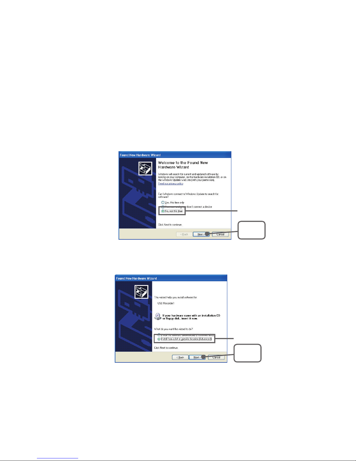
By connecting a data logger to your computer, the [Welcome to the
Found New Hardware Wizard] will automatically open.
- If it does not automatically open, please see the next page.
- If a window appears such as the one below, check [No, not this time]
and then click the [Next]
Button.
* Windows such as this will not appear for [No Service Pack] and [Service
Pack 1] versions.
Check
[Next]
Button
4.
By checking [Install the software automatically (Recommended)] and
clicking [Next], the software will automatically be installed.
Check
[Next]
Button
5.
After completing installation, click the [Finished] Button.
Page 31
26
If the driver is not automatically detected
Follow the directions below to install.
1.
Disconnect the USB cable from the Data Collector and then re-connect it.
2.
The [Add New Hardware Wizard] will automatically open.
- If a window appears such as the one below, check [No, not this time]
and then click the [Next]
Button.
* Windows such as this will not appear for [No Service Pack] and
[Service Pack 1] versions
Check
[Next]
Button
3.
By checking [Install from a list or specific location(Advanced)] and
clicking [Next], the installation process will begin.
Check
[Next]
Button
Page 32
27
4.
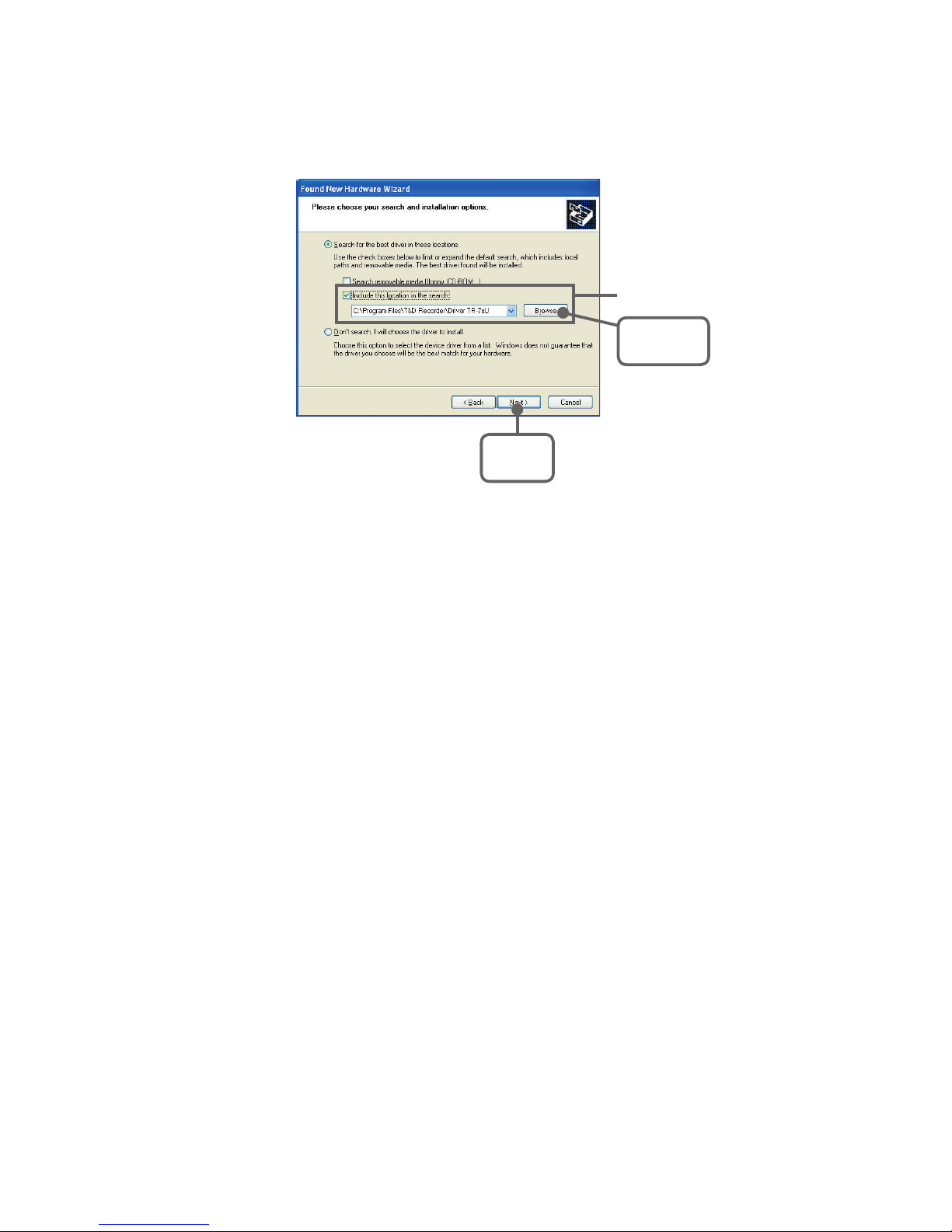
Place a check next to [Include this location in the search: ], click the
[Browse] Button and specify the location of the driver.
Check
[Browse]
Button
[Next]
Button
- Select the driver for the device being used from the folder where [T&D
Recorder for Windows ] was installed.
・ For TR/RTR-57U... Driver RTR-57U
- Insert the CD-ROM into the proper drive and from the CD-ROM select
the driver for the device being used.
・ For TR/RTR-57U... CD-ROM Drive ¥DeviceDriver ¥RTR-57U
5.
After having selected the correct driver, click [Next] to start the
installation.
After completing the installation, click the [Finished] Button.
Page 33
28
Confirming after Installation
1.
Connect the Data Collector to the Computer
- For details about connecting to the computer, see P.19.
2.
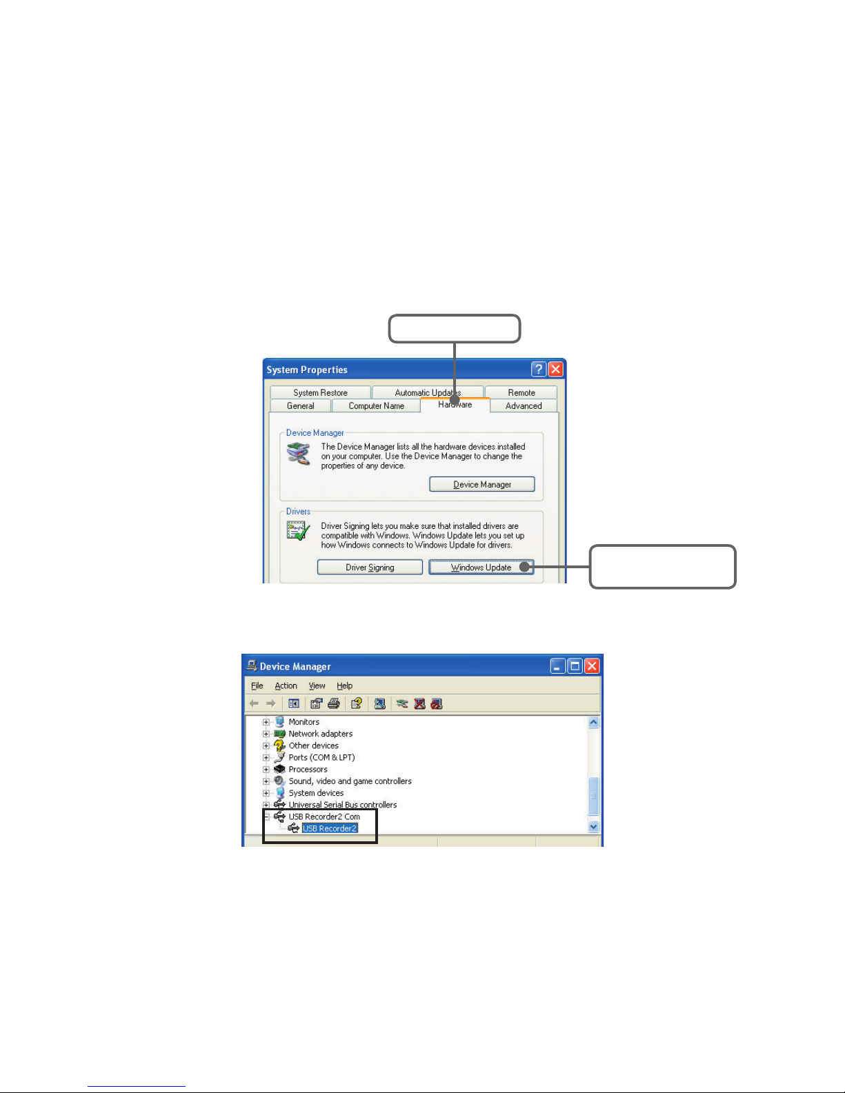
From the [Control Panel], click on [Performance and Maintenance] [System]; the system properties will be displayed.
3.
Click the [Hardware] Tab, and click the [Device Manager] Button in the
Device Manager Area.
[Device Manager]
Button
[Hardware] Tab
4.
In the Device Manager Window, check to see if [USB Recorder] is listed
under [USB Recorder Com]*1.
*1: For RTR/TR-57U... [USB Recorder2 Com] - [USB Recorder2]
Note
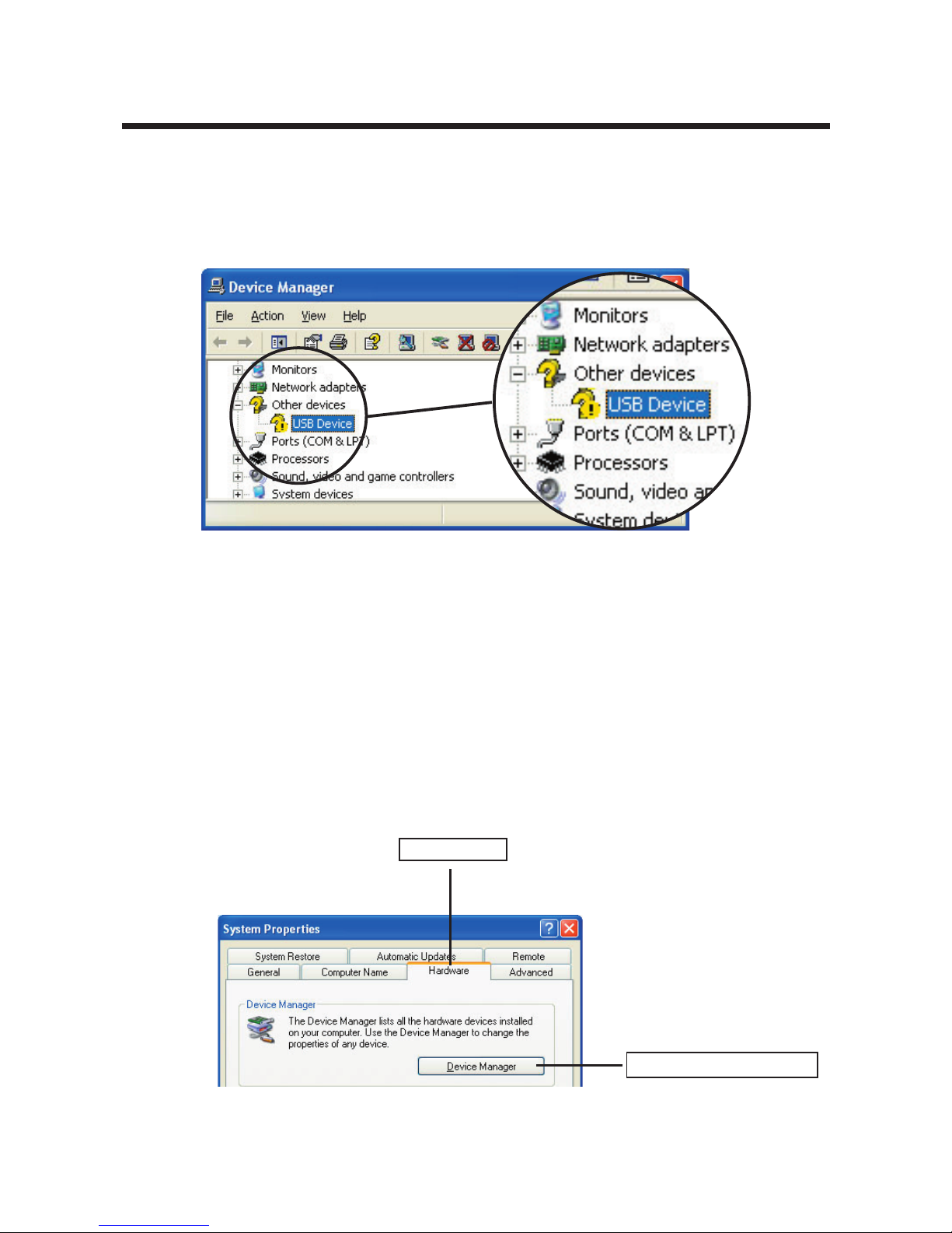
- If under [USB Recorder Com] – [USB Recorder*] there appears a ! or a ? ,
or if in the Device Manager Window [? Other device?! USB Device] appears; that
means the USB driver has not been installed properly. Please see [If USB Device
Driver Installation Fails] (p.29) and re-install the driver as instructed.
Page 34
29
If USB Device Driver Installation Fails
If, during USB device driver installation, some trouble occurs that
results in a failure to install properly, the following display will appear
in the Device Manager.
* For Windows XP
If this occurs, the USB device driver must be re-installed.
■ How to Re-install
* The images in the following explanation are taken from [Windows XP] .
They may differ from the windows that appear when using other
Operating Systems.
1.
In the [Control Panel], open [System].
2.
In the System Properties Window, click the [Hardware] Tab, and then
click the [Device Manager] Button in the Device Manager Area.
[Hardware]Tab
[DebiceManager]Button
Page 35
30
3.
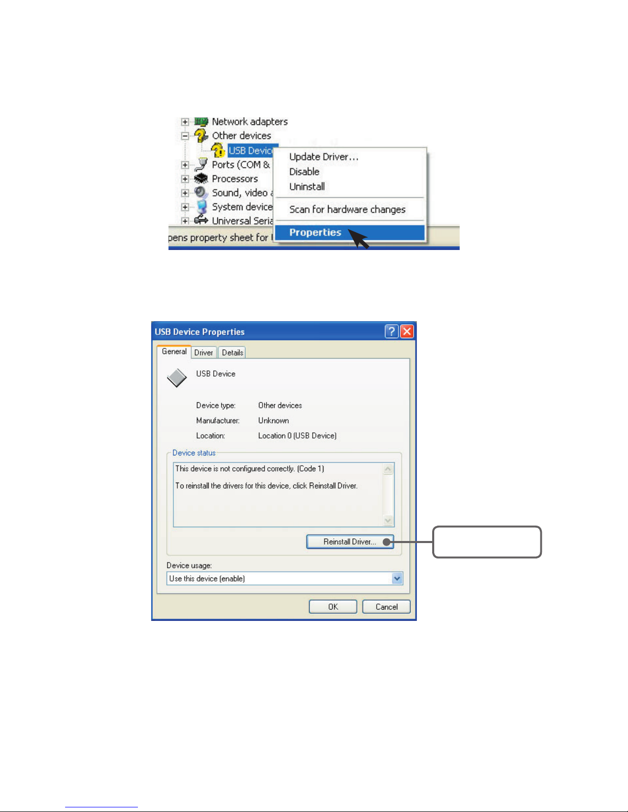
In the Device Manager Window, right click on [USB Device] under [Other
Devices] and then click on [Properties] to display the [USB Device
Properties] Window.
4.
In the USB Device Properties Window, click on the [Re-install Driver]
Button to display the Hardware Detection Wizard.
Follow the directions to install.
[Re-install Driver]
Button
Page 36
31
Setting Up the Communication Port
Check One
Possible
COM Ports
[Set] Button
[Auto Detect]
Button
When setting up more than one type at the same time
Detection Results [Communication Port Settings] Tab
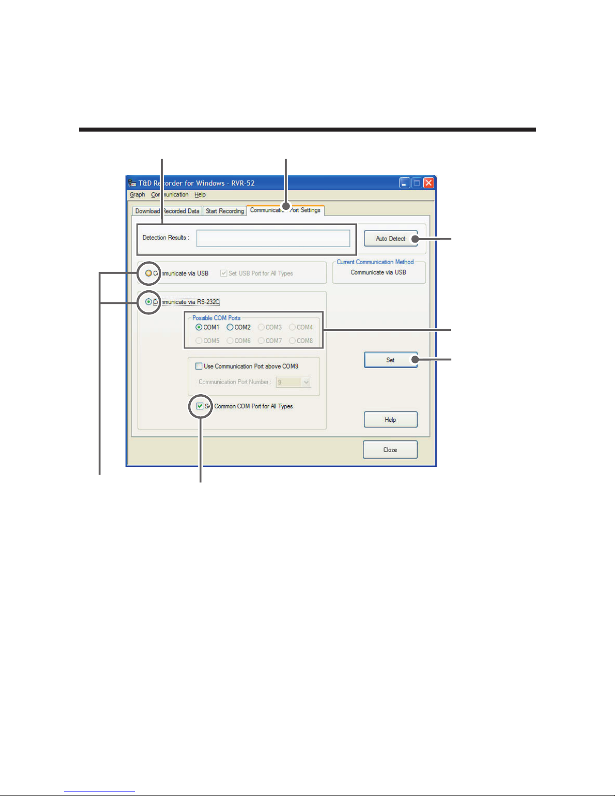
■ Communication via USB
1.
In the Toolbar of the Data Logger you are using, under [Communication]
select [Communication Port Settings
]. Open the Settings Window by
clicking the [Communication Port Settings] Tab.
2.
Place a check next to [Communicate via USB] and click the [Set] Button
to complete the settings.
3.
If you wish to set the same port for all types of devices put a check next
to [Set USB Port for All Types].
Page 37

32
■ Communication via RS-232C
When wishing to carry out communication using a serial
communication cable, please make serial port settings.
Set which serial port you would like to use to communicate with the
Data Logger. There are two methods to make the settings: [AutoDetect] and [Select Serial Port].
Connect the serial cable to port you wish to use and then connect it
to the logger.
If you wish to use the same Communication Port for several types of
devices.
Place a check next to [Set Common COM Port for All Types] and
click [Set] Button and port settings can be done for all devices in
one step.
[Auto Detect] Button
1.
In the main window, open the Setting / Communication Display of the
type of Data Logger connected to the computer and click the
[Communication Port Settings] Tab.
2.
Click the [Auto Detect] Button to start the detection process.
3.
When the detection is completed, a message will be displayed in the
[Detection Results] section.
4.
By clicking the [OK] Button, the setting process will be finished and the
port to which the data logger is connected will be set.
5.
By clicking the [Close] Button, the setting will be completed.
[Set] Button
Fixes the settings you have made in the dialog box.
[Close] Button
Closes the dialog box.
Page 38
33
Remote Unit Registration
To carry out wireless communication between a Data Collector
(RTR-57 Series) and a Remote Unit (RTR-51/52/52Pt for
temperature, RTR-53 for temperature and humidity, or RVR-52A for
voltage and pulse), it is first necessary to register all remote unit
information and make all pertinent settings.
In the Launcher Window, click the [Remote Unit Registration] icon;
this will open the Remote Unit Registration Window.
* It also possible to open the [Remote Unit Registration] in the
[Communication] Menu for each type of device.
Note
- The RTR-52Pt is only compatible with RTR-57U version 3 or higher.
■ Registering a Remote Unit
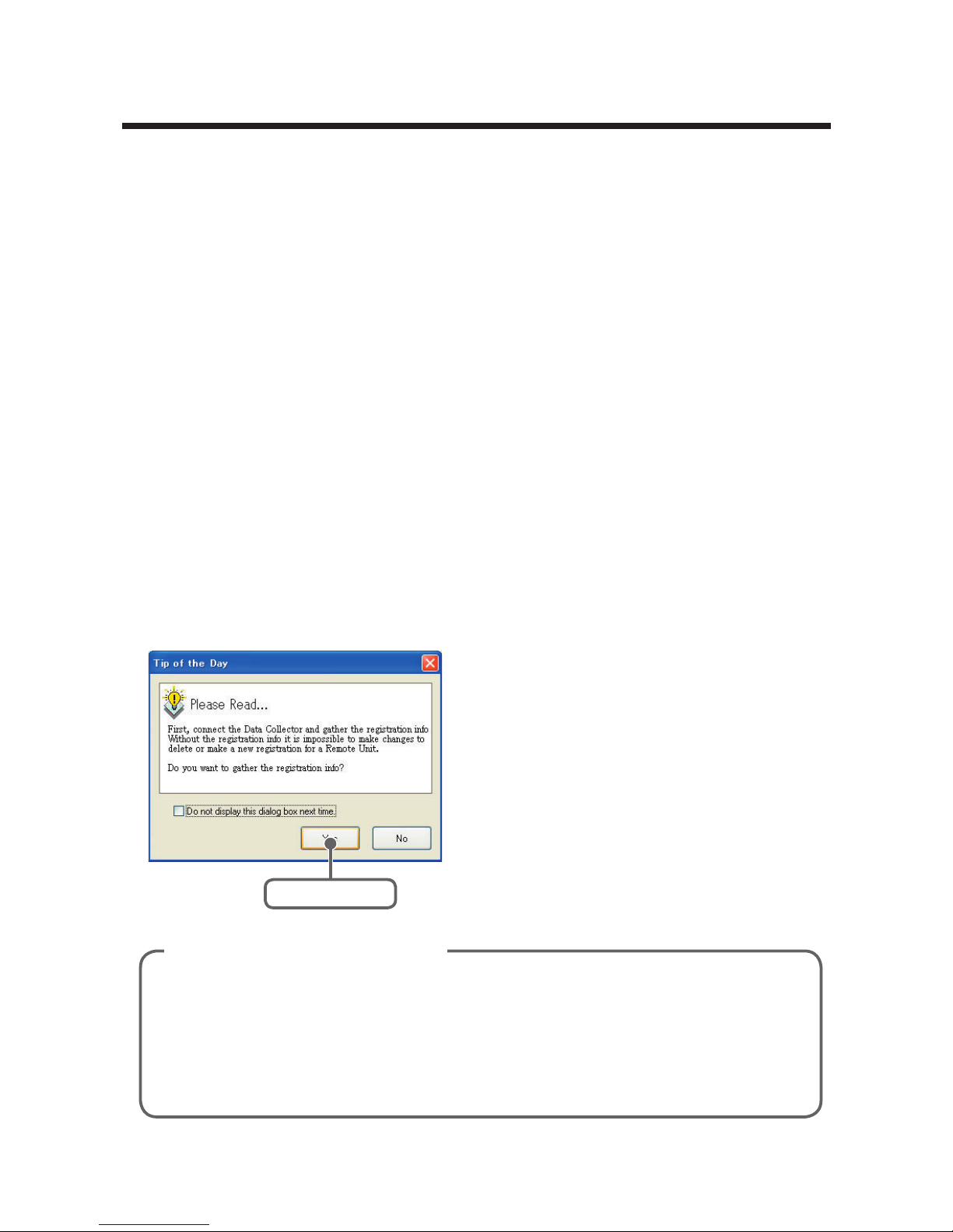
By selecting the icon [Remote Unit Registration], a message will be
displayed.
* Remote Unit Registration can be carried out for each type of unit from
the Setting / Communication Menu for that unit [Communication][Remote Unit Registration].
This function allows you to collect all Remote Unit Registration info in
the RTR-57C/57U. That info (Group Name / Remote Unit Number /
Remote Unit Name) will be displayed in a list. In order to delete,
change or register any groups or remote units in an RTR-57C/57U, it is
necessary to connect that RTR-57C/57U to your computer and carry
out the [Collect Registration Info] before proceeding.
Collect Registration Info
[Yes] Button
After the [Please Read...] message
appears, by clicking the [Yes] Button
the gathering of Remote Unit
registration info will begin.
Page 39
34
Button
Functions
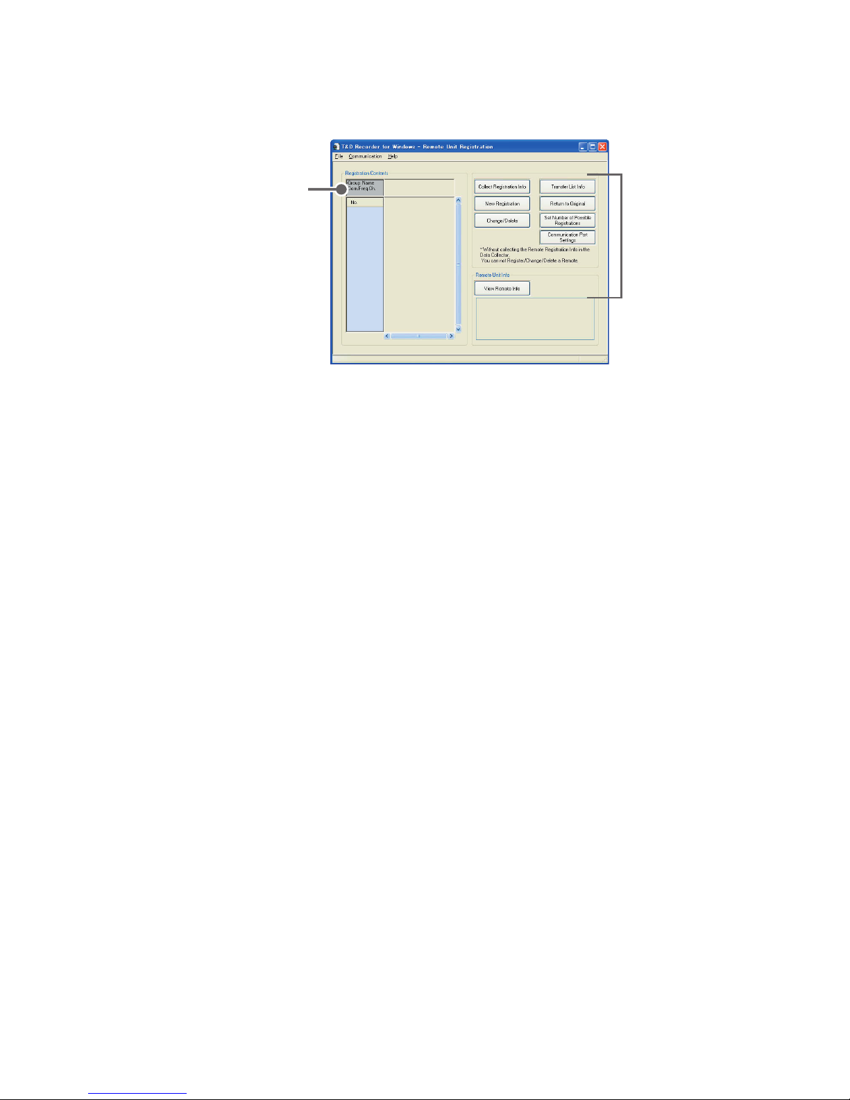
Registration Contents
See p.35 for details
[Collect Registration Info] Button
It is possible to gather remote unit registration info for all Remote Units
registered in the Data Collector. (See P.35)
[New Registration] Button
Set up a new Remote Unit registration; the contents will be registered in both
the Remote Unit and the Data Collector. (See P.36)
[Change / Delete] Button
Change or delete the Remote Unit Registration Contents in the Data Collector.
(See P.41)
[Transfer List Info] Button
Transfer the contents of Remote Unit Registration File to a Data Collector.
This is especially useful when setting up a number of Data Collectors with the
same registration contents. (See P.42)
[Return to Original] Button
Use this to re-initialize a Data Collector's Remote Unit Registration Contents.
(See P.41)
[Set Number of Possible Registrations] Button
Set registration mode by choosing possible number of groups and remote
units to be registered. (See P.40)
[Communication Port Settings] Button
Make communication port settings here. (See P.31)
[View Remote Info] Button
By pressing this you can view the registration info for the Remote Unit that is
currently placed on the Data Collector. (SeeP.43)
Page 40
35
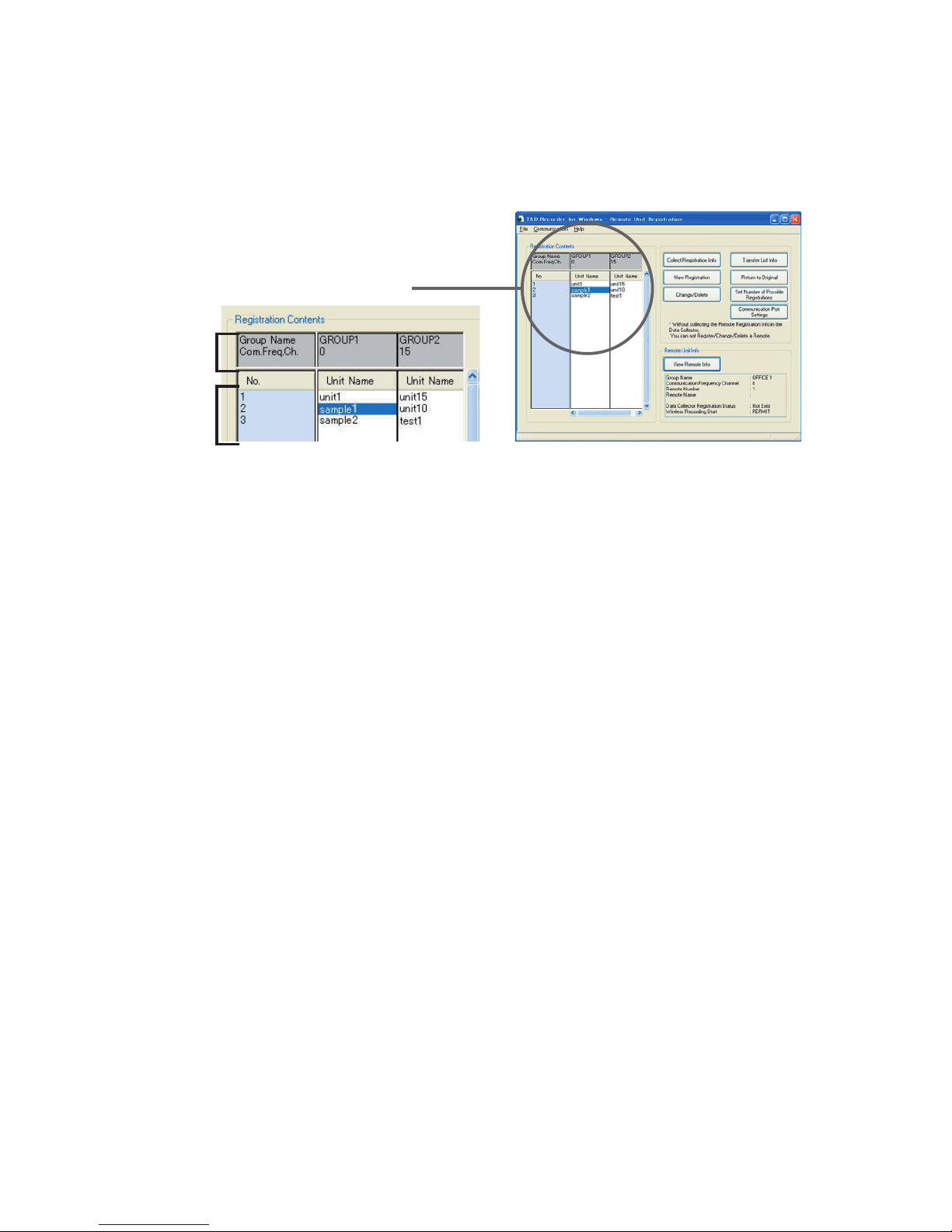
■ [Collect Registration Info] Button
Displays remote registration info for all units registered to that Data
Collector.
1st Column (dark gray background)
Group Name View a List of currently registered Groups.
Com. Freq. Ch View the Communication Frequency Channel for the
Groups being displayed.
2nd Column (light blue background)
Number View the Remote Unit Numbers
The Remote unit info will appear under the Group into
which it has been registered.
If the empty remote number the info area will be left blank.
[Remote Unit Registration] Window
2nd
Column
1nd
Column
Ex. of a
[Registration Contents] display
Page 41
36
■ [New Registration] Button
1.
Place the Remote Unit (Data Logger) you wish to register face down on
top of the Data Collector and click the [New Registration] Button.
Note
- If no Remote Unit is on top of the Data Collector or no Remote unit can be found,
a confirmation message will appear after which the info will be registered in the
Data Collector only.
- If the info is only registered in the Data Collector and no Remote Unit contains
that same info wireless communication cannot occur, so please be careful when
registering units.
- If you wish to register a multiple number of Remote Units to the same Group,
proceed by placing and replacing the Remote Units you wish to register on the
Data Collector and carry out registration for each one.
2.
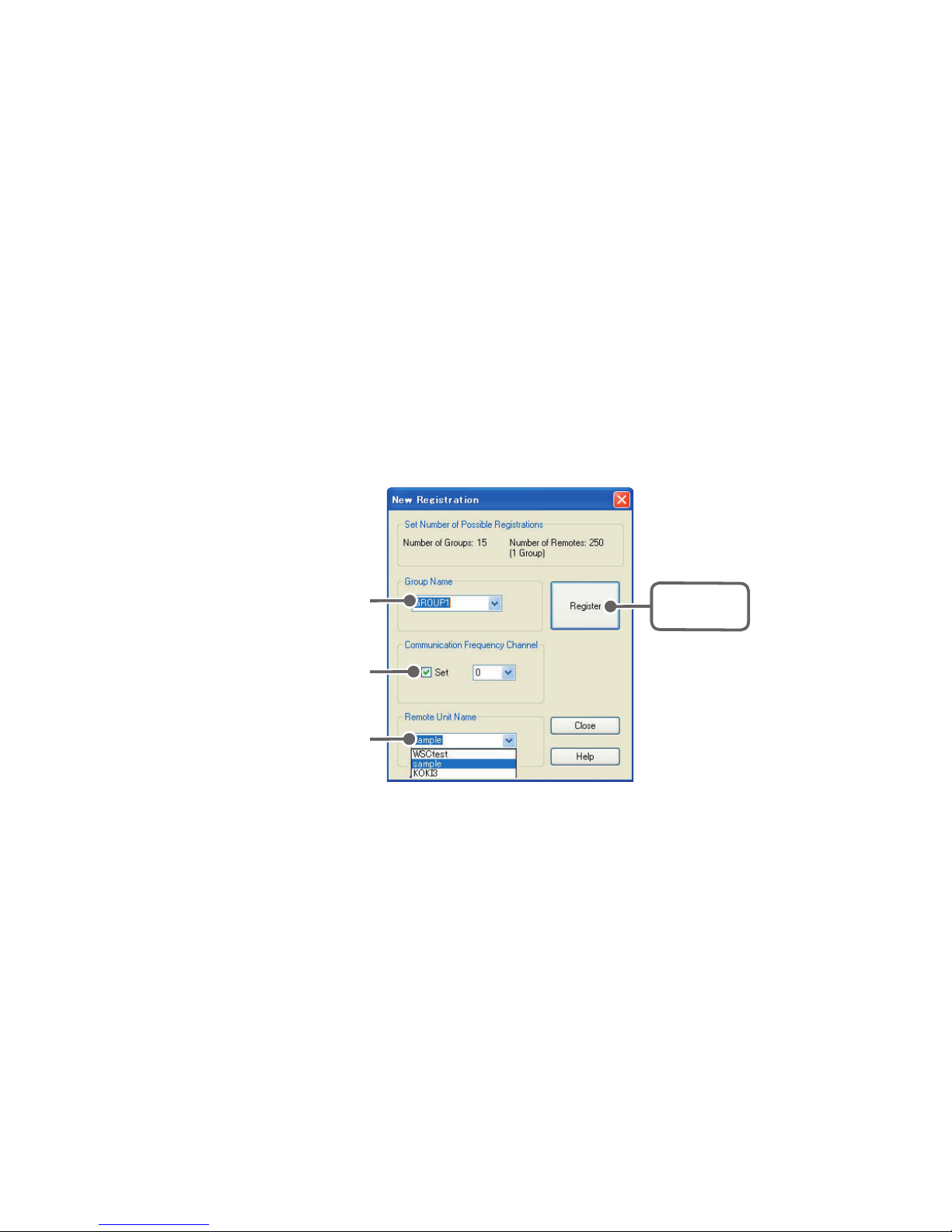
Set the Group Name, Remote Name, and Communication Frequency
Channel.
[
Register
]
Button
Group Name
Communication
Frequency Channel
Remote Unit
Name
3.
By clicking the [Register] Button, registration will be completed.
- If you are registering a number of remote units to the same group,
place each one on top of the RTR-57C/57U and carry out the
registration into the same group.
- If you are registering units to different group names, please follow the
above steps over again.
Page 42
37
4.
Upon completion the [Registration Contents] will be displayed and by
clicking [Close] the registration will be finished and the window closed.
Note
- By clicking on a Group Name, the Frequency Channel for that group, as well as,
the Remote Unit Name(s) and Number(s) in that group will be displayed
.
[Group Name]
- Group Names can be entered with up to 8 letters.
- You can also select an already registered group name and make slight
changes to make a new name.
- If you are using a multiple number of Data Collectors (RTR-57C/57U) and
register units using the same Group name, communication may occur with a
Remote Unit registered to a different Data Collector (RTR-57C/57U).
Hence, if you are using a multiple number of Data Collectors, please register
units making sure to use different Group names for each Data Collector.
[Remote Unit Name]
- Remote Names can be entered with up to 8 letters.
- You can also select an already registered remote name and make slight
changes to create a new name.
[Communication Frequency Channel]
- By clicking the [Set] check box you can select a channel number.
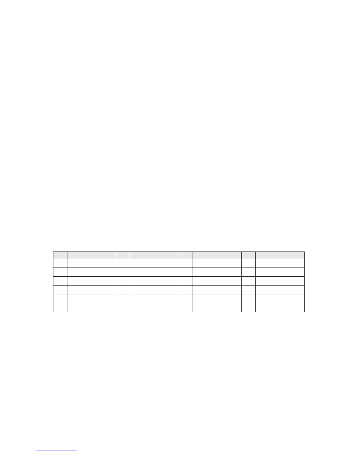
- One Frequency Channel (0 to 21) can be set for each Group.
CH Frequency(MHz) CH Frequency(MHz) CH Frequency(MHz) CH Frequency(MHz)
0
902.28072
6
909.358608
12
916.436496
18
923.514384
1
903.460368
7
910.538256
13
917.616144
19
924.694032
2
904.640016
8
911.717904
14
918.795792
20
925.87368
3
905.819664
9
912.897552
15
919.97544
21
927.053328
4
906.999312
10
914.0772
16
921.155088
5
908.17896
11
915.256848
17
922.334736
Note
- The default frequency channel setting for Group 1 is '0'
- If no settings are chosen, an unused frequency channel will be automatically
assigned.
- A frequency channel setting can only be made when registering a new group.
- Once a channel has been set for a group it cannot be changed.
- The specified frequency channel will be used for all communication with remote
units in that group. If another RTR-57C/57U is using the same channel in the same
area, communication may become unstable.
Page 43
38
■ Confirming after Registration
Position the remote unit(s) in the place(s) where you want to
measure and check if communication is possible.
From an RTR-57C/57U unit, it is possible to find any registered
Remote Unit and make sure communication can be carried out.
1.
In the Main Window, activate [Find Remotes].
2.
Choose the range in which to search and activate.
- If you choose [All Groups], the search for remotes in all registered
groups will begin immediately.
- If you choose [Specify Group], select the desired group from the list to
start the search.
3.
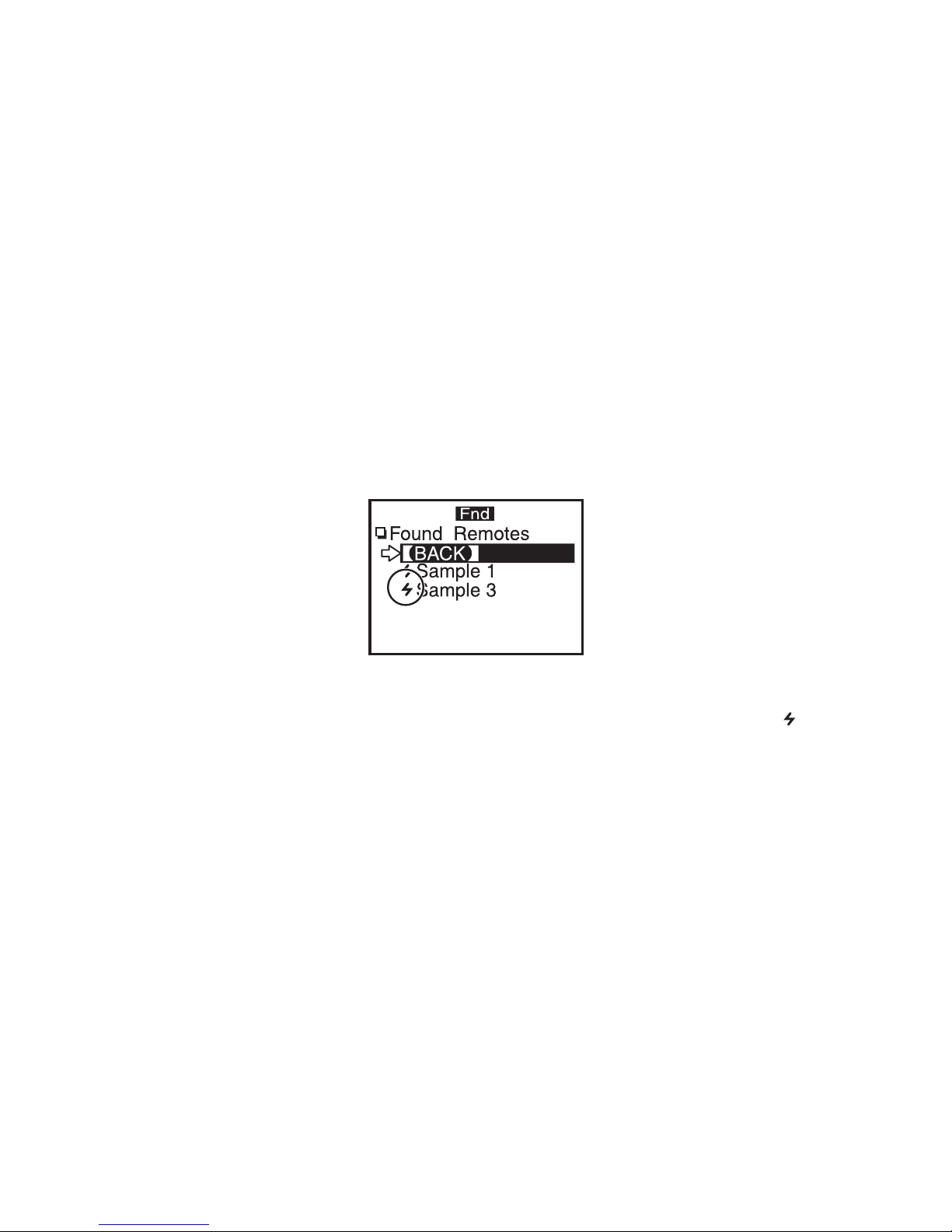
After the search has been completed, a list of possible Remote Units for
communication will appear in a list.
Note
- Remote Units for which communication is possible will be marked with an [ ]
before its name
.
- For details, please see the RTR-57C/57U User's Manual.
Page 44

39
Other Remote Unit Registration Functions
The following operations can be carried out in the Remote
Registration Window. Be sure to connect the RTR-57C/57U to your
computer and collect the registration info of RTR-57C/57U before
carrying out these operations.
■ Saving Registration Contents to File: [File] Menu
You can save the Group and Remote Unit Registration Info to a file.
1.
From the [File] Menu, choose [Save Registration Contents to File].
2.
Designate the saving location and enter a file name.
3.
Click the [Save] Button to save the file.
Note
- You cannot edit the contents of registration info from a saved file.
- You cannot send text file.
■ Saving as Text File: [File] Menu
You can save the Group and Remote Unit Registration Info as a text
file.
1.
From the [File] Menu, choose [Save as Text File].
2.
Designate the saving location and enter a file name.
3.
Click the [Save] Button to save the file.
Note
- You cannot edit the contents of registration info from a saved file.
Page 45
40
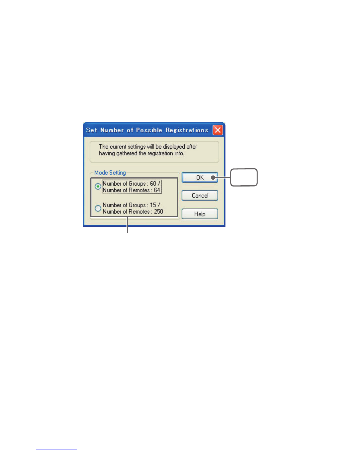
■ [Set Number of Possible Registrations] Button
There are two patterns for setting and registering the largest number
of groups and remotes into one RTR-57C/57U.
1.
Select a pattern.
2.
Click [OK] Button to complete the change.
Select a Pattern
Pattern 1: Number of Groups: 60 / Number of Remotes in 1 Group: 64
Pattern 2:
Number of Groups: 15 / Number of Remotes in 1 Group: 250
[OK]
Button
Note
- The Default Setting is Pattern 1.
- If you wish to monitor using the [All Groups] range, it is possible to monitor only 120
Remote Units. Therefore, either register only 120 Remote Units to the Group or
select to monitor using the [Specify Group] range.
- If changes are made to the pattern, the Remote Unit Registration Contents saved in
the RTR-57C/57U will be automatically returned to the original default contents.
Please be careful.
Page 46
41
■ [Return to Original] Button
All info saved in the RTR-57C/57U will be erased and will be
returned to as it was when it left the factory: Group Name: Group 1 /
Remote Unit: NONE / Communication Frequency: 0
1.
Connect the RTR-57C/57U unit you wish to return to the factory
settings.
2.
Click the [Return to Original] Button, and the process will begin.
■ [Change/Delete] Button
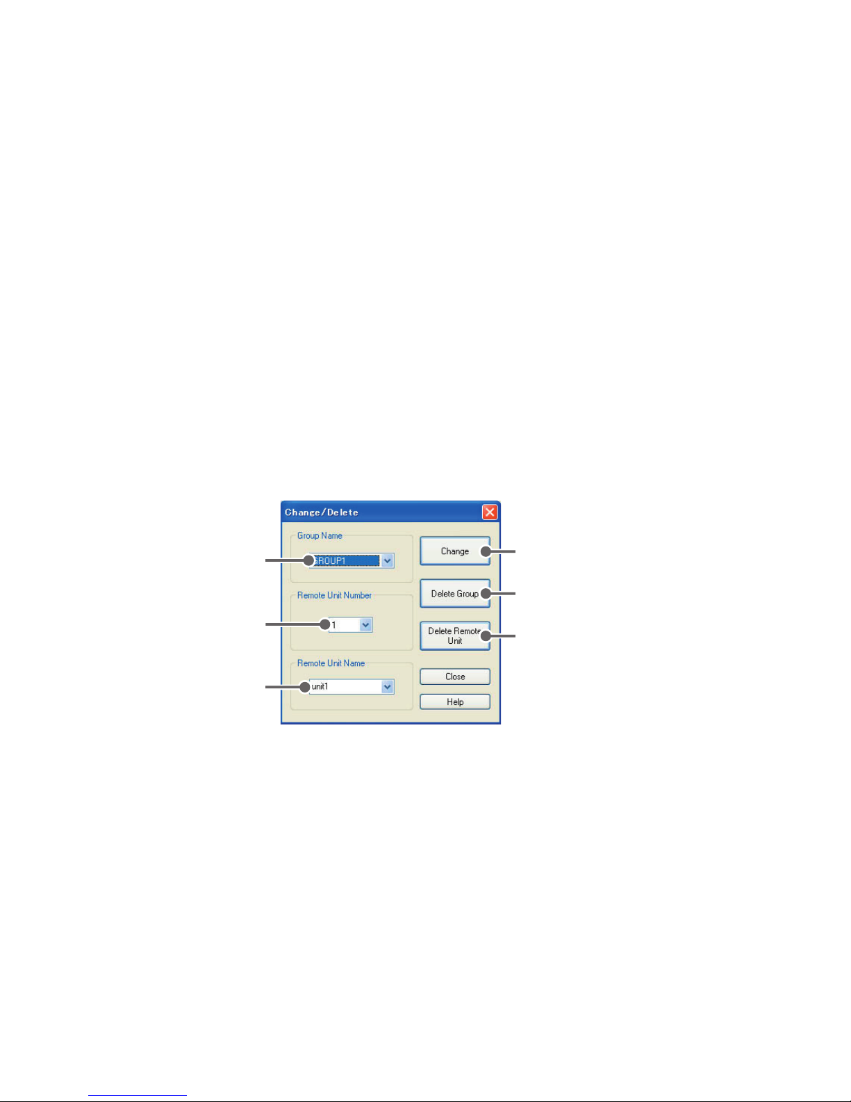
You can make changes to a registered Remote Unit Name or delete
a Group or Remote Unit.
[Change] Button
[Delete Group] Button
[Delete Remote
Unit] Button
Group Name
Remote Unit
Number
Remote Unit
Name
[Change] Button
If a Remote Unit is placed on top of the Data Collector, the changes for the
selected info will be performed in both the Data Collector and the Remote
Unit. If no Remote Unit is on top of the Data Collector or no Remote unit can
be found, a confirmation message will appear after which the info will be
registered in the Data Collector only.
Note
- By sending, you will delete all prior registration contents.
- If the info is only registered in the Data Collector and no Remote Unit contains such
info (Group name, frequency channel, remote number are all not the same) wireless
communication cannot occur, so please be careful when registering units.
Page 47

42
[Delete Group] Button
Deletes a selected Group. When deleting a Group all remote Unit Registration
Info for that Group will also be automatically deleted, so please take care
when deleting Groups.
[Delete Remote Unit] Button
- If a Remote Unit is placed on top of a Data Collector to which it is registered,
the Remote Unit Registration Info will be deleted from both the Remote Unit
and the Data Collector.
- If it is a Remote Unit not registered to that Data Collector, a confirmation
message will appear, after which the registration info will be deleted from
only the Data Collector.
- If no Remote Unit is on top of the Data Collector or no Remote unit can be
found, a confirmation message will appear after which the registration info
will be deleted from only the Data Collector.
- After deletion of info from a Remote Unit, the unit will be returned to its
original default settings.
■ [Transfer List Info] Button
- If the registration contents of two or more Data Collectors
(RTR-57C/57U) are the same, it is possible for communication to
occur between a number of Data Collectors and 1 Remote Unit.
- By sending the registration contents from the saved file of one
RTR-57C/57U to another Data Collector, it is possible to easily
create a multiple number of Data Collectors with the same
registration contents.
- By opening the saved Remote Registration File (extension.mnf)
you can view the saved registration info list. After confirming the
contents, click the [Transfer List Info] Button.
Note
- After the transfer has been completed, the previous registration contents will be
overwritten.
- Please make changes to the Number of Possible Registrations. (See P.40)
Page 48
43
■ [View Remote Info] Button
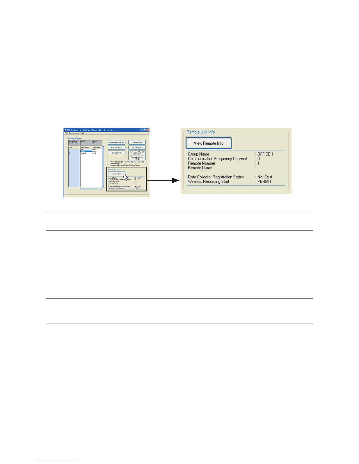
This allows you to view the registration contents of any Remote Unit
presently connected to the RTR-57C/57U. The Registration
Contents of units registered to a different RTR-57C/57U can be
viewed as well.
Ex. of a [Registration Info List] display
[Remote Unit Registration] Window
Group Name The Group Name to which the Remote Unit belngs.
Communication Frequency
Channel
The Communication Frequency Number for the Group to
which Remote Unit belongs Channel Number
Remote Number The Number of the Remote unit
Remote Name Data Logger Registration Status
Data Collector Registration
Status
Exist : If remotes are registered the presently connectid
RTR-57C/57U
Not exis
: If remotes are not registered in the presently
connected RTR-57C/57U
ーー : If registration info has not been collected from
presently connected RTR-57C/57
U
Wireless Recording Start Save wireless recording start settings
If forbidden to recording :
FORBID
If permission to start recording :
PERMIT
Page 49
44
RTR-51/52/52Pt: Start Recording
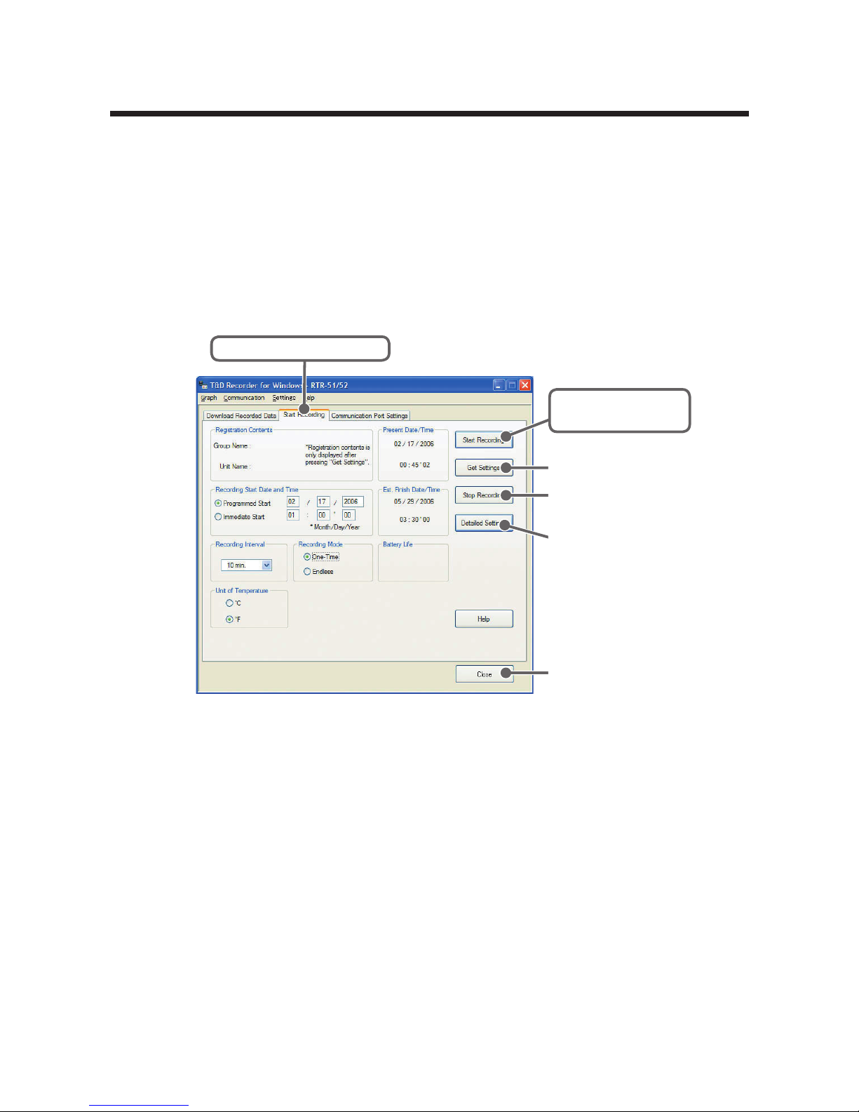
Here all settings and communication for RTR-51/52/52Pt (Wireless
Temperature Data Loggers) can be carried out. Connect a RTR-51
/
52/52Pt Data Logger to your computer so that communication can occur and
check to make sure that your computer system clock is correct.
* For details about connecting the Data Logger, Please see P.21 for details.
1.
In the Main Window, click the icon [RTR-51/52].
2.
Click the [Start Recording] Tab and make recording settings.
[Start Recording]
Button
[
Stop Recording
]
Button
[
Close
]
Button
[
Detailed Settings
]
Button
[Get Settings] Button
[Start Recording] Tab
Recording Start Date and Time
Select the Recording Start Method
- Programmed Start: Recording will begin on the day and time entered.
- Immediate Start: Recording will begin as soon as settings are
completed.
Recording Interval
Select from : 1, 2, 5, 10, 15, 20, 30 seconds
1, 2, 5, 10, 15, 20, 30, 60 minutes. By clicking [ ▼ ] you
can select from the recording interval list
.
Recording Mode
- One-time : When the number of readings has reached 16,000, the unit
display will read [FULL] and recording will automatically stop.
- Endless : When the number of readings reaches 16,000, the next one
will overwrite the oldest or first reading.
Page 50

45
Temperature Unit
Change the display of temperature on the Thermo Recorder between [℃]
and [ ゜F ].
- By clicking the [Get Settings] Button, registration contents and
remaining battery life will be displayed.
Note
- Note that when measuring and recording in Fahrenheit with RTR-52Pt, although
it is possible to measure between -327.8 and 1112 degrees, the LCD on the
Logger can only show between -199.9 and 999.9 degrees.
3.
After making all the desired settings, click the [Start Recording] Button
to transmit them.
4.
After transmission has been completed the communication result will
appear. By clicking [OK], the set-up process will be finished. By clicking
[Close], you can close the window.
[Get Settings] Button
The Remote Unit recording settings, registration contents, and
remaining battery life are displayed.
- Registration contents : If a settings transmission was received it displays the
Group and Remote Name(s).
- Remaining battery life : If a settings transmission was received it displays
the remaining battery life.
[Stop Recordings] Button
Stop current recording of Data Logger.
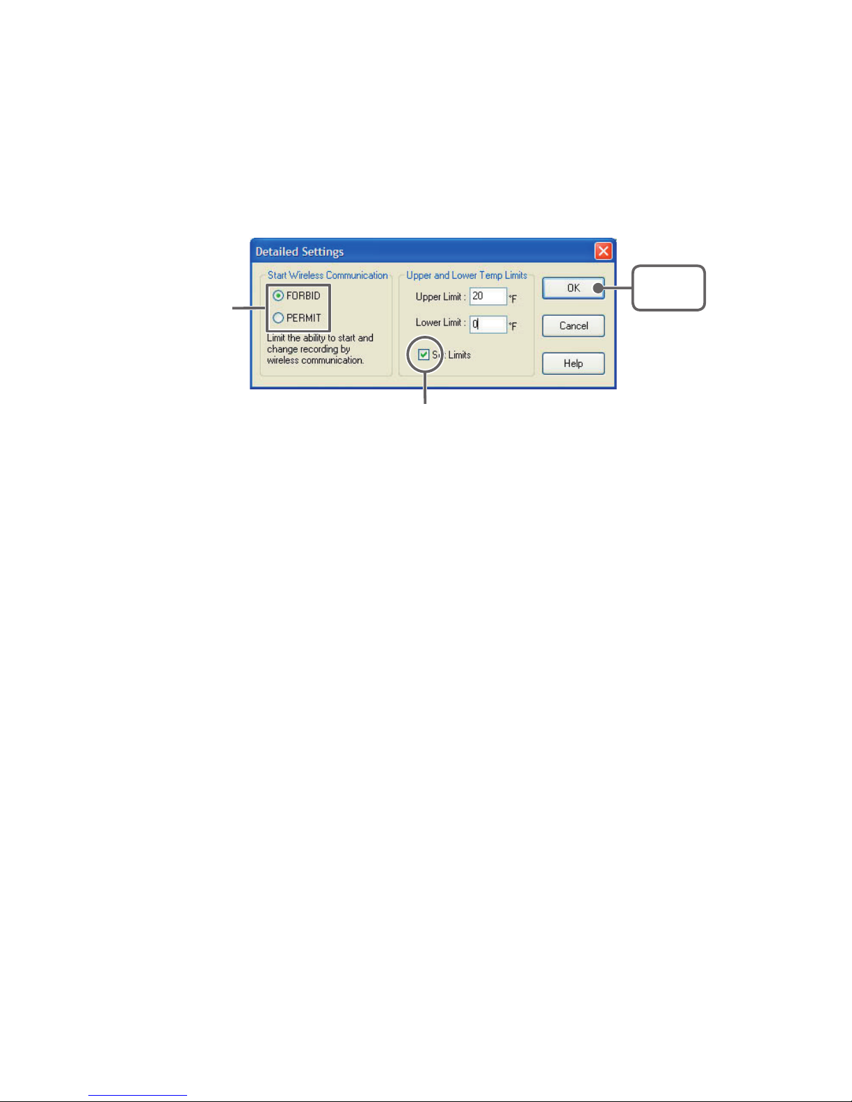
[Detailed Settings] Button
Making Detailed settings, before click [Start Recording] Button.
- Start Wireless Communication
Recording can normally be started by wireless communication between a
Data Collector and a RTR-51/52/52Pt Logger, but by choosing [FORBID],
permission will not be granted to start recording by wireless communication,
thereby preventing accidental recording from occurring.
If you wish to forbid the starting of recording by wireless communication,
check [FORBID]; to allow, check [PERMIT].
Note
- The Default Setting is [PERMIT]
Page 51
46
- Upper and Lower Limits
The Data Collector (RTR-57C/57U) can judge whether or not the recorded
data that it has downloaded is within the set upper and lower limits.
By
checking the [Set Limits] box
, Make sure to make entries in the following
ranges depending upon the device: for RTR-51 between -40 and 80℃ (-40
and 176
゜F), for RTR-52 between -60 and 155℃ (-76 and 311 ゜F), and for
RTR-52Pt between -200 and 600℃ (-327.8 and 1112
゜F).
Check one
[OK]
Button
By checking, you can make entries.
Page 52
47
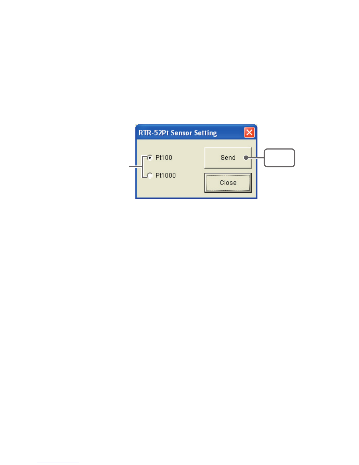
■ Sensor Settings (RTR-52Pt)
Make sensor settings for the sensor being used with the RTR-52Pt.
In the [Setting] Menu, select [RTR-52Pt Sensor Setting] to open the
setting window.
Note
- By changing the sensor, the current recording session will be automatically stopped.
[Sensor Setting] window
[Send]
Button
Check either
"Pt100" or "Pt1000".
1.
Place a check next to the sensor type you wish to use.
2.
Click the [Send] Button to send the setting change.
Page 53
48
RTR-51/52/52Pt: Downloading Recorded Data
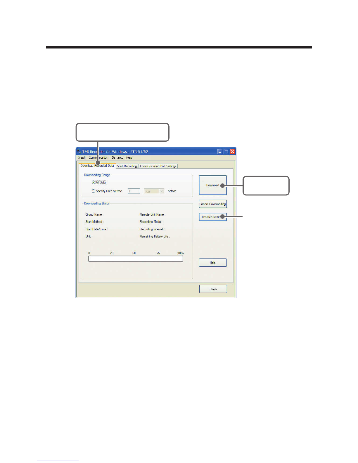
Connect the RTR-51/52/52Pt Unit for Communication with your
Computer.
* For details about connecting the Data Logger, please see P.21 for details.
1.
In the Main Window, click the icon [RTR-51/52].
2.
Click the [Download Recorded Data] Tab.
[Download]
Button
[Detailed Settings]
Button
[Download Recorded Data]
Tab
3.
After selecting the downloading range, click the [Download] Button to
start downloading.
4.
When downloading has been completed a graph will be displayed.
- If you have checked [After downloading, specify file in which to save
data] in the Detailed Settings, please view the graph after specifying
the file in which you wish to save the downloaded data.
Page 54
49
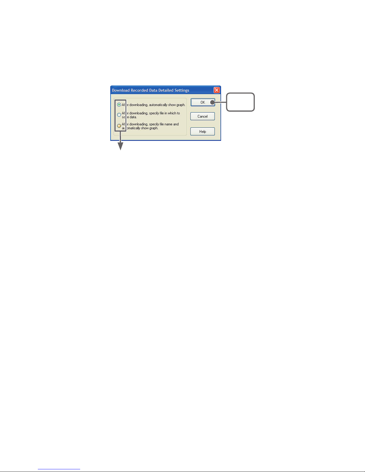
[Detailed Settings] Button
You can make settings for the processing of the downloaded recorded data.
Check one
[OK]
Button
- After downloading, automatically show graph
After data has been downloaded it will automatically be displayed in the Temp /Humidity
graph Window.
The File is not saved and if necessary should be done separately.
- After downloading, specify file in which to save data
After data has been downloaded, the [Save File] dialog box will appear wherein you can
save the data to a specified file.
- After downloading, specify file name and automatically show graph
The data is saved to the specified file and the graph for that file is automatically opened
in the Temp / Humidity Graph Window.
Page 55
50
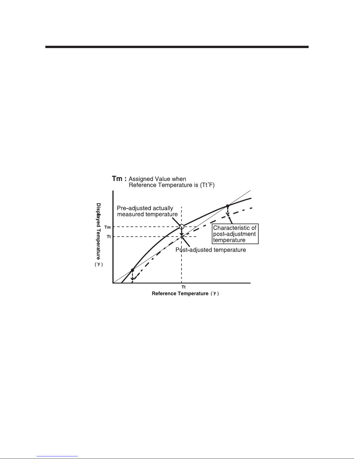
RTR-51/52/52Pt: Value Adjustment Function
This function enables the user to make adjustments to measured
values to correct inaccuracies that may occur when compared to a
standard or reference temperature measurement. By setting an
adjustment equation beforehand, the adjustment function will
automatically calculate to record and display the post-adjusted
measurement. It is possible to select from two methods of
adjustment: 1-point adjustment and 2-point adjustment.
Note
- By changing the sensor, the current recording session will be automatically stop
■ Temperature: 1-point Adjustment
Adjustment is carried out by entering the value of the difference between the
displayed temperature measurement reading and the reference one to which
it is being compared.
- Please set so that the possible adjustment range is within ± 54 °F.
Page 56
51
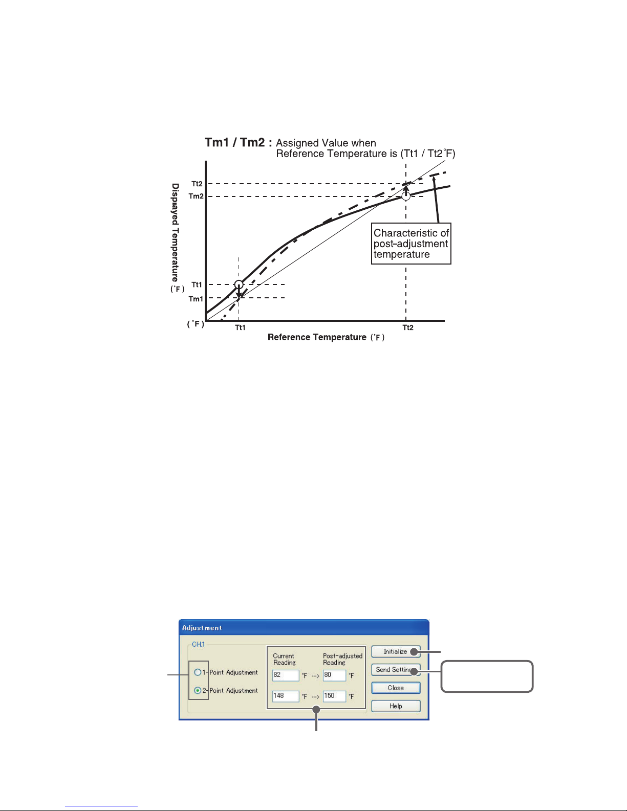
■ Temperature: 2-point Adjustment
Adjustment is carried out by entering values for the differences between two
displayed temperature measurement readings and the reference ones to
which they are being compared.
- Please set so that the possible adjustment range is within ± 5 °F.
■ Adjustment Settings
1.
Please follow directions as found in [Communication between Data
Loggers and Computers] by connecting the RTR-57U unit to your
computer and place the Data Logger unit face down on top of it.
(see p.21 for details)
2.
In the Main Window, click on the Data Logger icon. To open the
[Adjustment (RTR-51/52)] or [Adjustment (RTR-52Pt)] Window, click on
[Settings] in the Menu Bar and then select [RTR-51/52 Adjustment
Setting] or [RTR-52Pt Adjustment Setting] from the pull down menu.
[
Initialize
]
Button
[
Send Settings
]
Button
Enter current and post-adjusted reading(s)
Select 1-point
Adjustment or
2-point
Adjustment
Page 57

52
3.
Select either [1-point Adjustment] or [2 Point Adjustment].
4.
Please enter the actual pre-adjusted value(s) in the [Current Reading]
column and the post-adjusted reference value(s) in the [Post-adjusted
Reading] column.
5.
Click on the [Send Settings] Button to send the adjustment equation to
the selected Data Logger.
[Initialize] Button
Clears any previous adjustment equation(s) from the Data Logger.
[Send Settings] Button
Transmits the adjustment equation to the Data Logger.
[Close] Button
Quits and closes the window.
Note
- We cannot guarantee that after carrying out adjustment the measuring accuracy will
improve for all measuring ranges.
- By carrying out adjustment on an already adjusted device without first clicking the
Initialize Button, the new adjustment equation will be be used to further adjust the
previously adjusted result. It is important to remember that if adjustment takes place
without initializing the device, the adjustment will include the first equation as well as
the second and an over adjustment will occur. This over adjustment will be
especially large when making a 2-point adjustment and the measurement falls
outside of the range of the two points entered.
When you are carrying out adjustments and formulating equations please take care
with the settings and take personal responsibility for the process.
Page 58
53
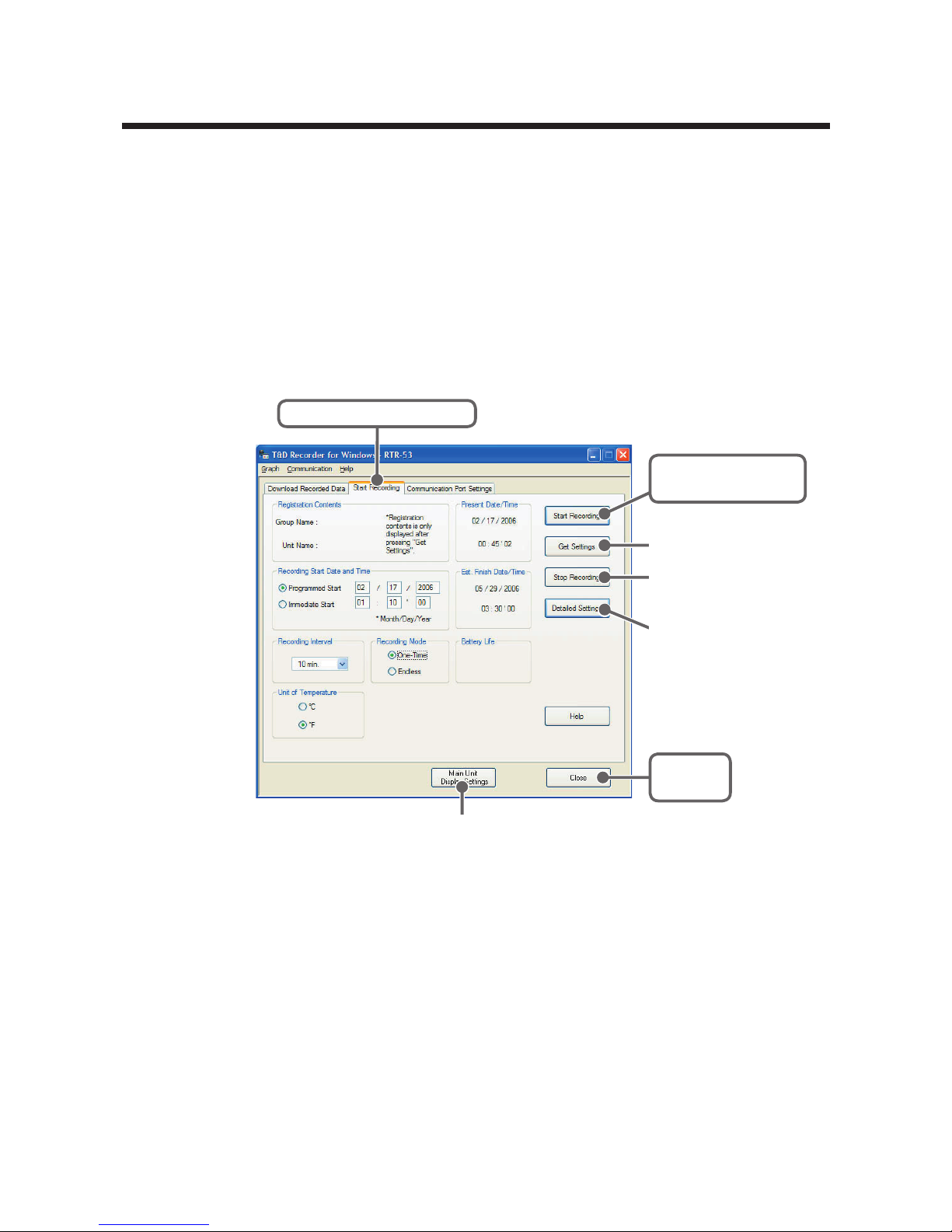
RTR-53 : Start Recording
Here all settings and communication for RTR-53 (Wireless Temperature/
Humidity Data Loggers) can be carried out.
Connect a RTR-53 Data Logger to your computer so that communication
can occur and check to make sure that your computer system clock is
correct.
* For details about connecting the Data Logger, please see P.21 for details.
1.
In the main window, click the icon [RTR-53].
2.
Click the [Start Recording] Tab and set the recording conditions.
[Close]
Button
[Start Recording]
Button
[Get Settings] Button
[Stop Recording]
Button
[Detailed Settings]
Button
[
Main Unit Display Settings
]
Button
[Start Recording] Tab
Recording Start Date and Time
Select the Recording Start Method.
- Programmed Start :Recording will begin on the day and time entered.
- Immediate Start :Recording will begin as soon as settings are
completed.
Recording Interval
Select from : 1, 2, 5, 10, 15, 20, 30 seconds
1, 2, 5, 10, 15, 20, 30, 60
minutes.
By clicking [ ▼ ] you can select from the recording interval list.
Page 59
54
Recording Mode
- One-time : When the number of readings has reached 16,000, the unit
display will read [FULL] and recording will automatically stop.
- Endless : When the number of readings reaches 16,000, the next one
will overwrite the oldest or first reading.
Temperature Unit
Change the display of temperature on the Thermo Recorder between [℃]
and [ ゜F ].
- By clicking the [Get Settings] Button, registration contents and
remaining battery life will be displayed.
3.
After making all the desired settings, click the [Start Recording] Button
to transmit them.
4.
After transmission has been completed the communication result will
appear. By clicking [OK], the set-up process will be finished. By clicking
[Close], you can close the window.
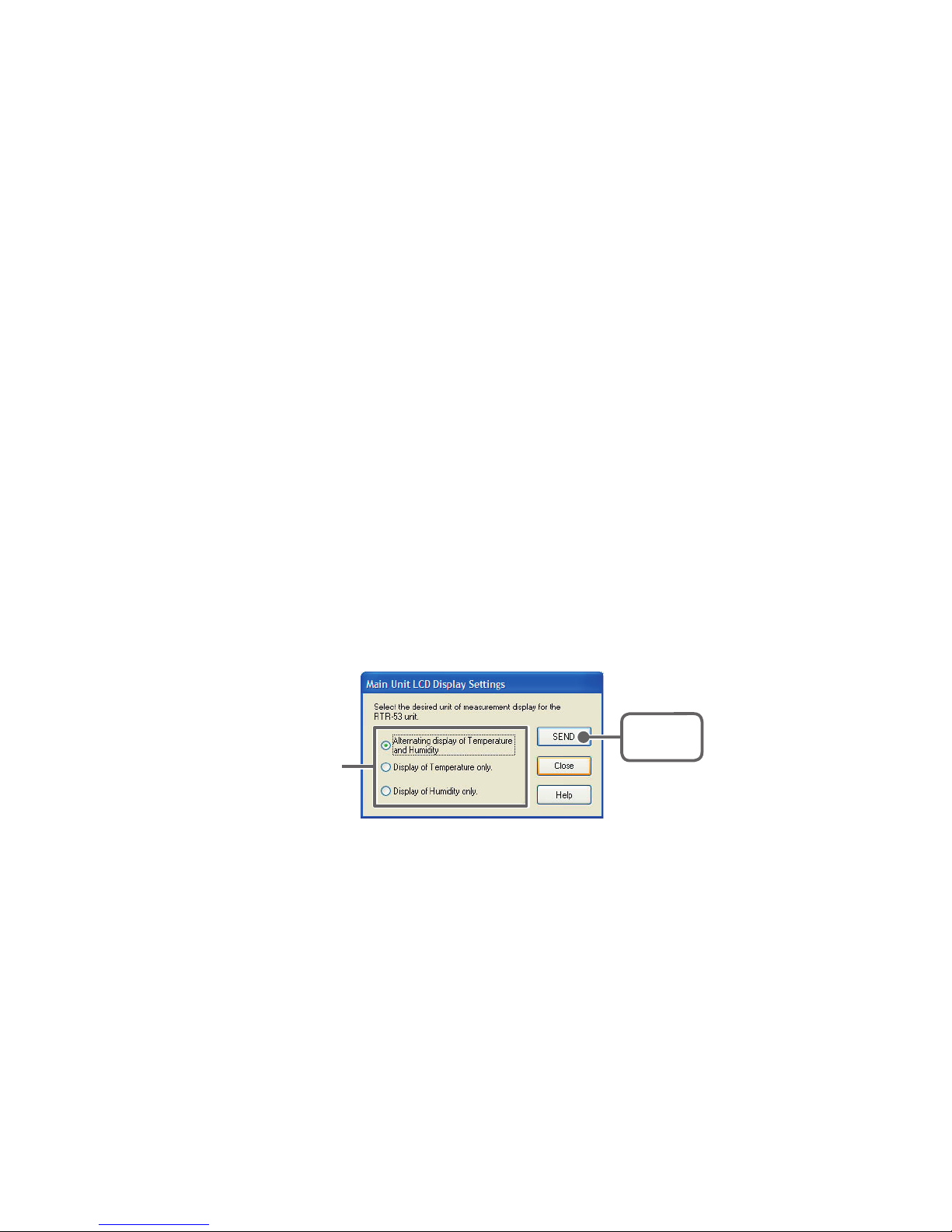
[Main Unit Display Settings] Button
Set the desired unit of measurement display for the RTR-53 unit LCD display.
1.
Select the unit of display you wish to set.
2.
Click the [Send] Button to complete the setting.
[SEND]
Button
Check one
[Get Settings] Button
The Remote Unit recording settings, registration contents, and remaining
battery life are displayed.
- Registration contents : If a settings transmission was received it displays the
Group and Remote Name(s).
- Remaining battery life : If a settings transmission was received it displays
the remaining battery life.
[Stop Recording] Button
Stop current recording of Data Logger.
Page 60
55
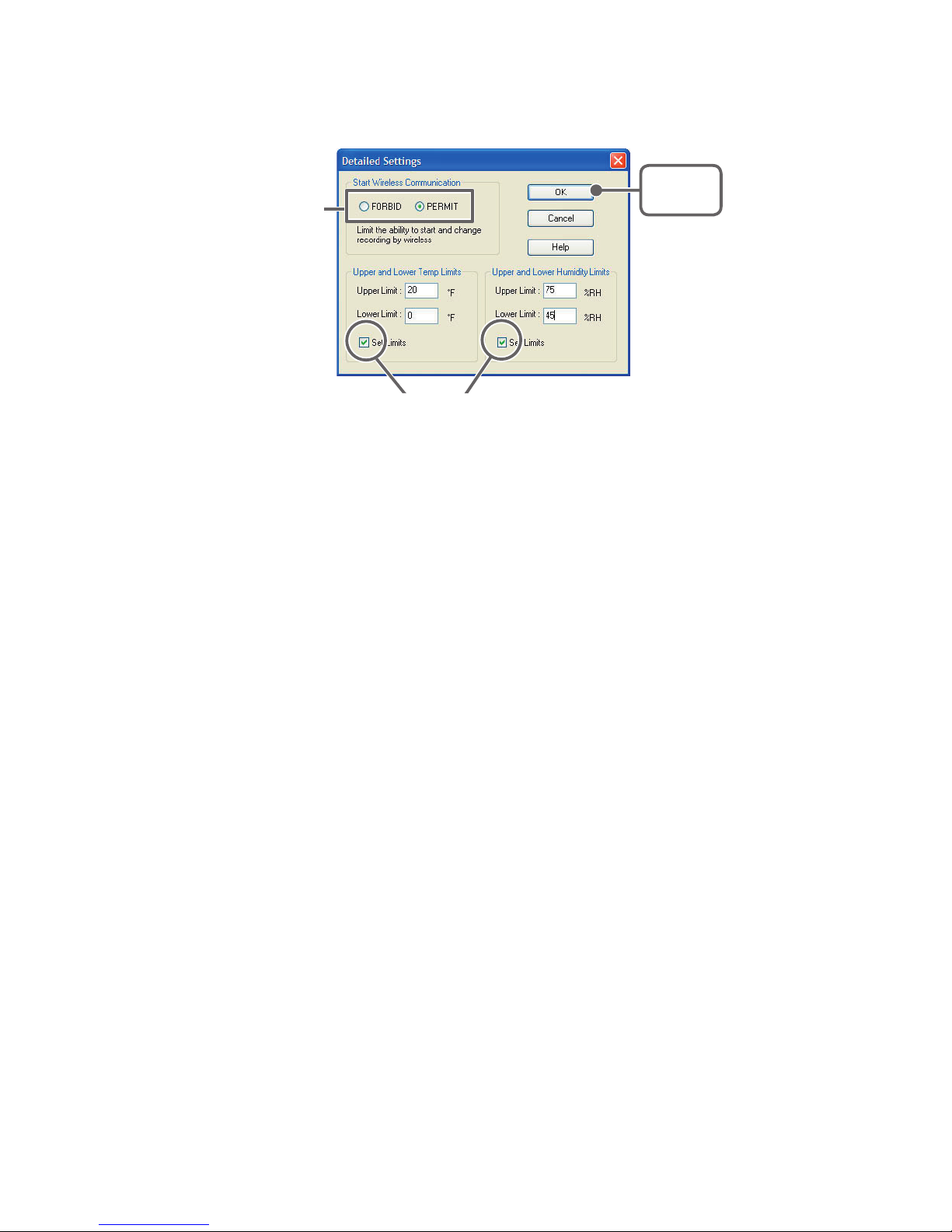
[Detailed Settings] Button
Making Detailed settings, before click [Start Recording] Button.
Check one
[OK]
Button
By checking, you can make entries.
- Start Wireless Communication
Recording can normally be started by wireless communication between a
Data Collector and a RTR-53 Logger, but by choosing [FORBID], permission
will not be granted to start recording by wireless communication, thereby
preventing accidental recording from occurring.
If you wish to forbid the starting of recording by wireless communication,
check [FORBID]; to allow, check [PERMIT].
Note
- The Default Setting is [PERMIT].
- Upper and Lower Limits
The Data Collector (RTR-57C/57U) can judge whether or not the recorded
data that it has downloaded is within the set upper and lower limits. By
checking the [Set Limits] box, you will be able to enter an upper and lower
limit within the following conditions.
- Upper and Lower Temperature Limits: -40 to 80℃ (-40 to 176 ゜F)
(Decimals will automatically converted to units of 0.5℃ )
- Upper and Lower Humidity Limits: 0 to 100%RH (Integers only)
Page 61
56
RTR-53: Downloading Recorded Data
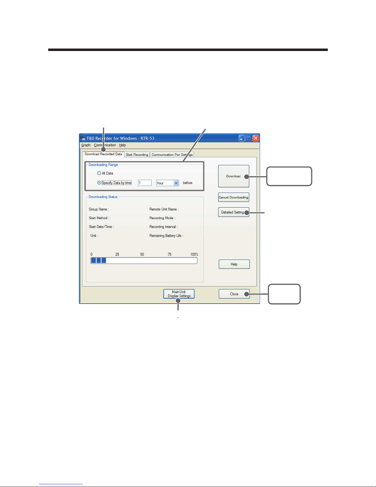
Connect the RTR-53 Unit for Communication with your Computer.
* For details about connecting the Data Logger, please see P.21 for details.
1.
In the Main Window, click the icon [RTR-53].
2.
Click the [Download Recorded Data] Tab.
[
Detailed Settings]
Button
[Download]
Button
[Close]
Button
[
Main Unit display Settings
]
Button
[
Download Recorded
Data
]
Tab
Select the downloading range
3.
After selecting the downloading range, click the [Download] Button to
start downloading.
4.
When downloading has been completed a graph will be displayed.
If you have checked [After downloading, specify file in which to save
data] in the Detailed Settings, please view the graph after specifying the
file in which you wish to save the downloaded data.
Page 62
57
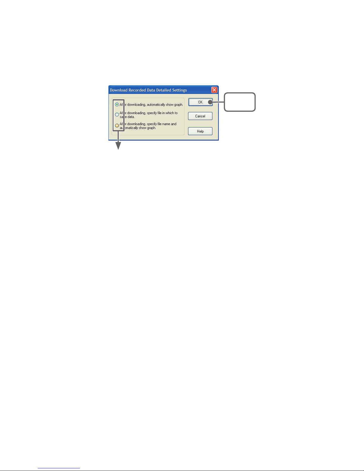
[Detailed Settings] Button
You can make settings for the processing of the downloaded recorded data.
Check one
[OK]
Button
- After downloading, automatically show graph
After data has been downloaded it will automatically be displayed in the Temp /Humidity
graph Window.
The File is not saved and if necessary should be done separately.
- After downloading, specify file in which to save data
After data has been downloaded, the [Save File] dialog box will appear wherein you can
save the data to a specified file.
- After downloading, specify file name and automatically show graph
The data is saved to the specified file and the graph for that file is automatically opened
in the Temp / Humidity Graph Window.
[Main Unit Display Settings] Button
Set the desired unit of measurement display for the RTR-53 unit LCD display.
Please see P.
55 for details.
Page 63

58
RTR-53 : Value Adjustment Function
This function enables the user to make adjustments to measured
values to correct inaccuracies that may occur when compared to a
standard or reference temperature measurement. By setting an
adjustment equation beforehand, the adjustment function will
automatically calculate to record and display the post-adjusted
measurement. It is possible to select from two methods of
adjustment: 1-point adjustment and 2-point adjustment.
Note
- When you are carrying out adjustments and formulating equations please take care
with the settings and take personal responsibility for the process.
■ Temperature/Humidity:1-point / 2-point
Adjustment
Before : Enter the actual measurement before adjustment
After : Enter the desired measurement after adjustment.
- Entries are valid to one decimal point.
- The input value for [Post-adjusted Reading] must be less than ± 5 ゜F /% in
comparison to the input value for [Current Reading].
■ Adjustment Settings
1.
Please follow directions as found in [Communication between Data
Loggers and Computers] by connecting the RTR-57U unit to your
computer and place the Data Logger unit face down on top of it. (see P.21
for detail)
2.
In the Main Window, click on the Data Logger icon. To open the
[Adjustment] Window, click on [Settings] in the Menu Bar and then
select [Adjustment Settings] from the pull down menu.
Page 64
59
3.
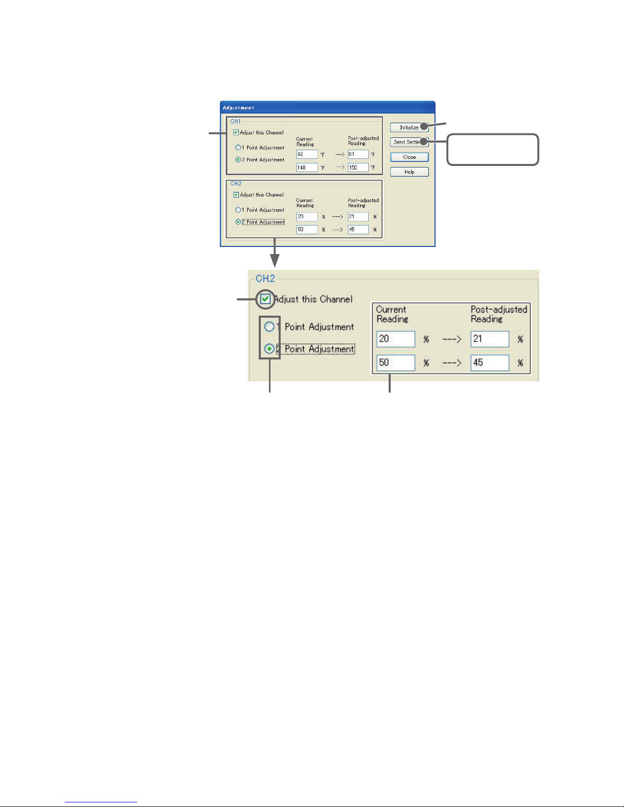
Check [Adjust this Channel], and select either [1-point Adjustment] or [2
Point Adjustment].
[
Initialize
]
Button
[Send Settings]
Button
Temperature
Adjustment
Humidity Adjustment
Select 1-point Adjustment or
2-point Adjustment
By checking,
you can make entries
Enter current and
post-adjusted reading(s)
4.
Please enter the actual pre-adjusted value(s) in the [Current Reading]
column and the post-adjusted reference value(s) in the [Post-adjusted
Reading] column.
5.
Click on the [Send Settings] Button to send the adjustment equation to
the selected Data Logger.
[Initialize] Button
Clears any previous adjustment equation(s) from the Data Logger.
[Send Settings] Button
Transmits the adjustment equation to the Data Logger.
[Close] Button
Quits and closes the window.
Page 65

60
Note
- We cannot guarantee that after carrying out adjustment the measuring accuracy will
improve for all measuring ranges.
- By carrying out adjustment on an already adjusted device without first clicking the
Initialize Button, the new adjustment equation will be be used to further adjust the
previously adjusted result. It is important to remember that if adjustment takes place
without initializing the device, the adjustment will include the first equation as well as
the second and an over adjustment will occur. This over adjustment will be
especially large when making a 2-point adjustment and the measurement falls
outside of the range of the two points entered.
When you are carrying out adjustments and formulating equations please take care
with the settings and take personal responsibility for the process.
(For details about the RTR-51/52/52Pt Temperature Adjustment Function. see p.50)
Page 66
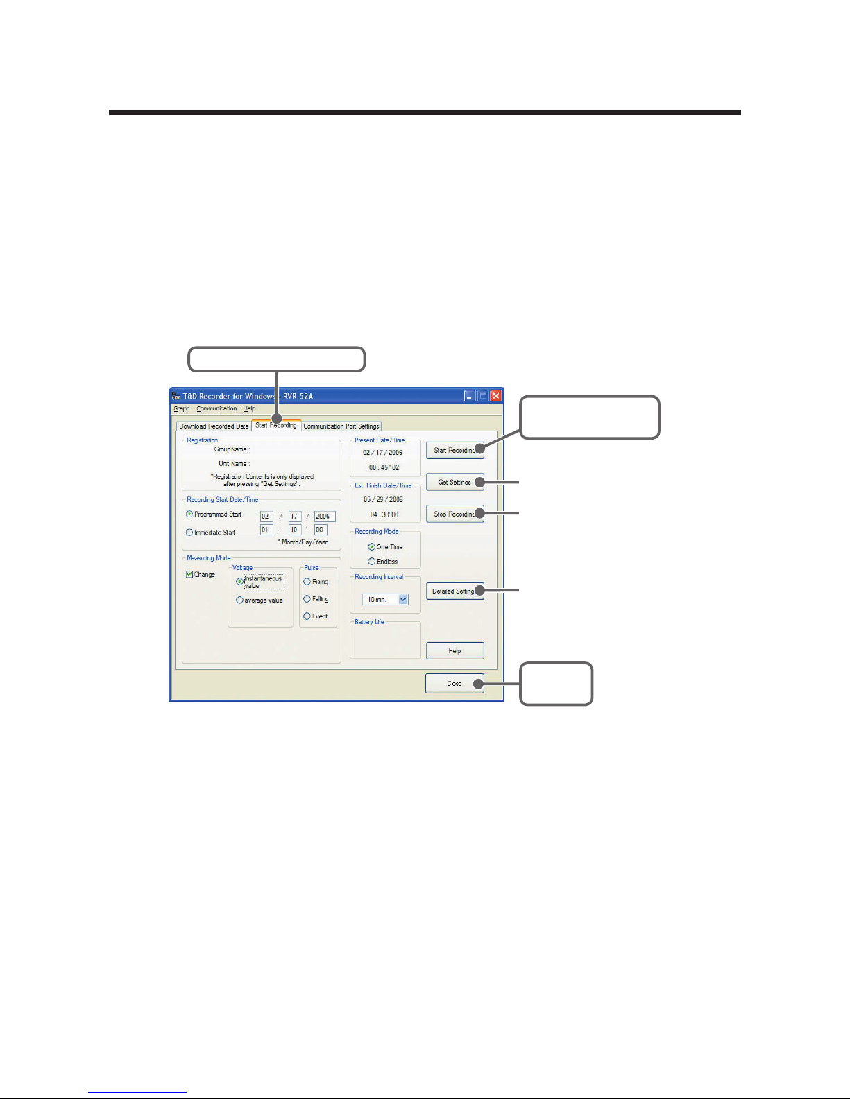
61
RVR-52A: Start Recording
Here all settings and communication for RVR-52A (Wireless Voltage /
Pulse Data Loggers) can be carried out. Connect a RVR-52A Data
Logger to your computer so that communication can occur and check
to make sure that your computer system clock is correct.
* For details about connecting the Data Logger, Please see P.21 for details.
1.
In the Main Window, click the icon [RVR-52A].
2.
Click the [Start Recording] Tab and make recording settings.
[Close]
Button
[Start Recording]
Button
[Get Settings] Button
[Stop Recording]
Button
[Start Recording] Tab
[Detailed Settings]
Button
Recording Start Date and Time
Select the Recording Start Method
- Programmed Start : Recording will begin on the day and time entered.
- Immediate Start : Recording will begin as soon as settings are
completed.
Recording Interval
Select from: 1, 2, 5, 10, 15, 20, 30 seconds
1, 2, 5, 10, 15, 20, 30, 60
minutes. By clicking
[ ▼ ] you can select from the recording interval list.
Recording Mode
- One-time : When the number of readings has reached 16,000, the unit
display will read [FULL] and recording will automatically stop.
- Endless : When the number of readings reaches 16,000, the next one
will overwrite the oldest or first reading.
Page 67

62
Note
- The start date and time for a programmed recording start is based upon your
computer system clock. If your computer clock is not set correctly, a programmed
recording start may not start properly.
- The estimated finish date and time of recording in one time mode will be
automatically calculated from the set recording interval and starting time.
Measurement Mode
Voltage (V)
Instantaneous Value : Record the voltage measurement as the
instantaneous value for each recording
Average Value :
Record as the average value for each recording
interval span. The average value for recording
intervals under 15 seconds will be calculated as
the average of the measurements from every 1
second. The average for intervals over 20 seconds
will be calculated as the average of the
measurements from every 2 seconds.
Moisture : Record Moisture by Percentage
The unit of measurement on the display will show
[%] for Percent
.
Pulse Lo → Hi : Record the number of signals rising within the
recording interval you have set.
Hi → Lo
: Record the number of signals falling within the
recording interval you have set.
Event
Hi ⇔ Lo : Record the time of any event; a rising (Lo to Hi)
or falling (Hi to Lo)
waveform that occurs for
more than 1 second at an input voltage range of
between 0 to 30V.
Preheat Time
The Preheat function turns on the power for a connected external
sensor to allow you to turn the sensor on for the measurement time only.
Here, you can select and set the amount of time you wish to have the
sensor turned on before measurement.
By clicking
[ ▼ ] you can select from 50msec, or from 1 to 200 seconds.
Note
- For details about the preheat function and its circuitry, see the RVR-52A User's
Manual.
3.
After making all the desired settings, click the [Start Recording] Button
to transmit them.
Page 68
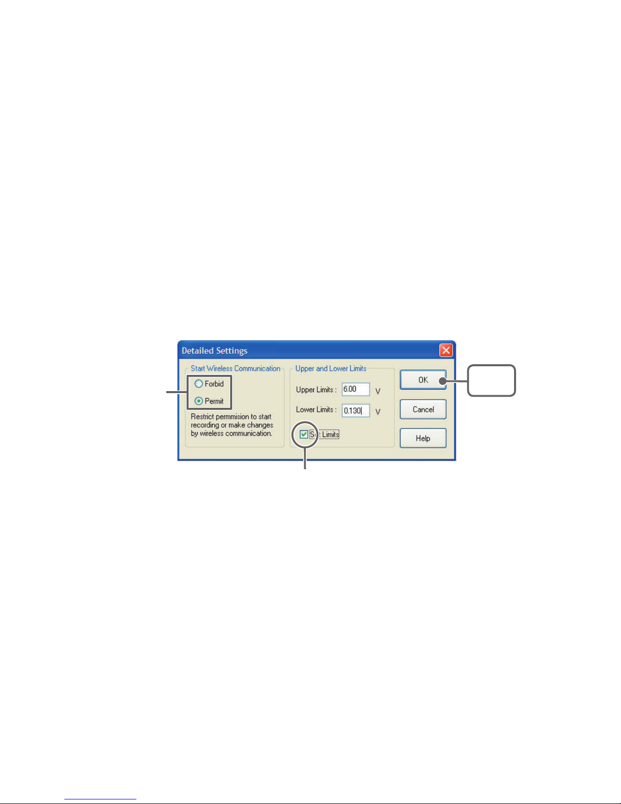
63
4.
After transmission has been completed the communication result will
appear. By clicking [OK], the set-up process will be finished. By clicking
[Close], you can close the window.
[Get Settings] Button
The Remote Unit recording settings, registration contents, and remaining
battery life are displayed.
- Registration contents: If a settings transmission was received it displays the
Group and Remote Name(s).
- Remaining battery life : If a settings transmission was received it displays
the remaining battery life.
[Stop Recordings] Button
Stop current recording of Data Logger.
[Detailed Settings] Button
Check one
[OK]
Button
By checking, you can make entries.
- Start Wireless Communication
Recording can normally be started by wireless communication between a
Data Collector and a RVR-52A Logger, but by choosing [FORBID],
permission will not be granted to start recording by wireless communication,
thereby preventing accidental recording from occurring.
If you wish to forbid the starting of recording by wireless communication,
check [FORBID]; to allow, check [PERMIT].
Note
- The Default Setting is [PERMIT].
Page 69

64
- Upper and Lower Limits
The Data Collector (RTR-57C/57U) can judge whether or not the recorded
data that it has downloaded is within the set upper and lower limits. By
checking the [Set Limits] box, you will be able to enter an upper and lower
limit within the following conditions.
- Upper and Lower Voltage Limits : 0.0 to 7.0 (V) (decimals are valid to the
third place)
- Upper and Lower Pulse Limits : 0 to 32000 (P) (Integers only)
Note
- When recording events, there are no Upper and Lower Limit settings to be made.
Page 70
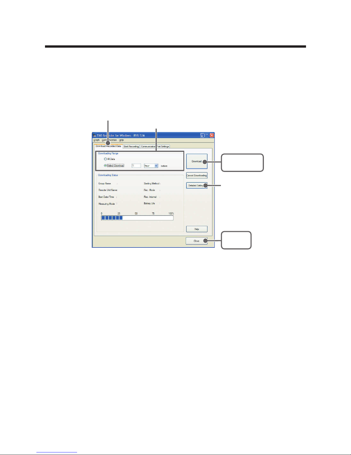
65
RVR-52A: Downloading Recorded Data
Connect the RVR-52A Unit for Communication with your Computer.
* For details about connecting the Data Logger, please see P.21 for details.
1.
In the Main Window, click the icon [RVR-52A].
2.
Click the [Download Recorded Data] Tab.
[
Detailed Settings
]
Button
[Download]
Button
[Close]
Button
[
Download Recorded
Data
]
Tab
Select the downloading range
3.
After selecting the downloading range, click the [Download] Button to
start downloading.
4.
When downloading has been completed, a Graph or Event Viewer will
be displayed.
If you have checked [After downloading, specify file in which to save
data] in the Detailed Settings, please view the Graph or Event Viewer
after specifying the file in which you wish to save the downloaded data.
Page 71
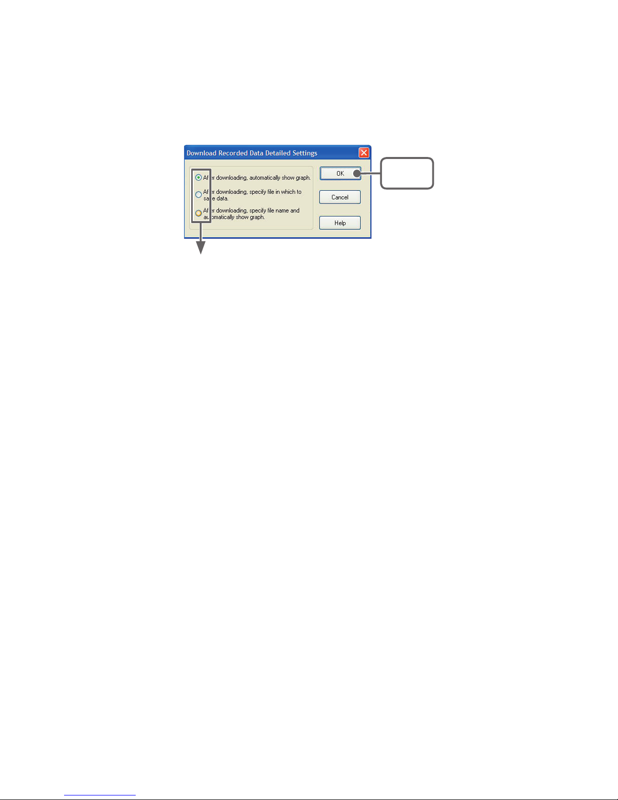
66
[Detailed Settings] Button
You can make settings for the processing of the downloaded recorded data.
Check one
[OK]
Button
- After downloading, automatically show graph
After data has been downloaded it will automatically be displayed in the Temp /Humidity
graph Window.
The File is not saved and if necessary should be done separately.
- After downloading, specify file in which to save data
After data has been downloaded, the [Save File] dialog box will appear wherein you can
save the data to a specified file.
- After downloading, specify file name and automatically show graph
The data is saved to the specified file and the graph for that file is automatically opened
in the Temp / Humidity Graph Window.
Page 72
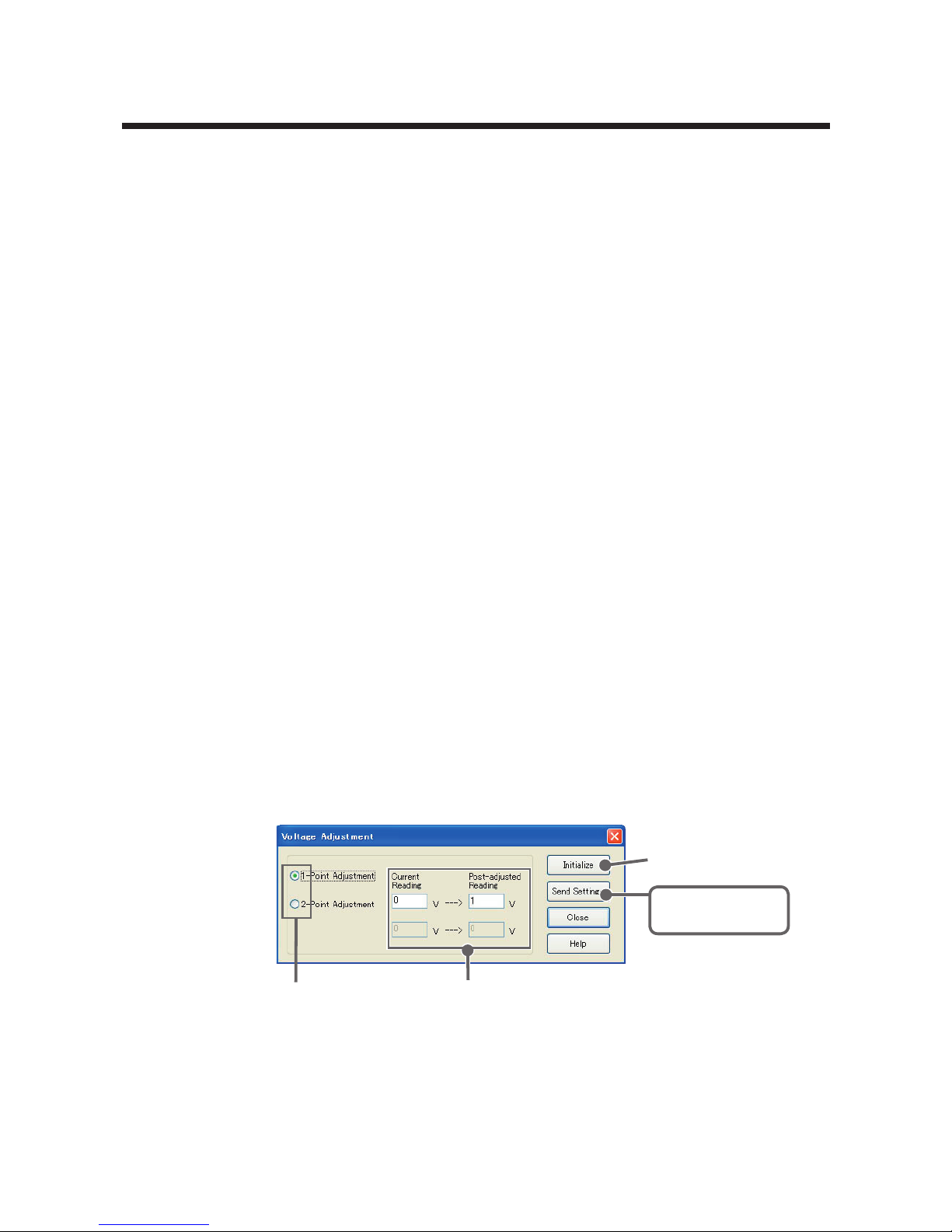
67
RVR-52A : Value Adjustment Function
This function allows you correct or adjust for errors in measurement
values. The Data Logger will record only the adjusted value.
Note
- When you are carrying out adjustments and formulating equations please take care
with the settings and take personal responsibility for the process.
■ Voltage : 1-point / 2-point Adjustment
Before : Enter the actual measurement before adjustment
After : Enter the desired measurement after adjustment.
- Entries are valid to one decimal point.
- The input value for [Post-adjusted Reading] must be less than ± 5 V in
comparison to the input value for [Current Reading].
■ Adjustment Settings
1.
Please follow directions as found [Communication between Data
Loggers and Computers] by connecting the RTR-57U unit to your
computer and place the Data Logger unit face down on top of it. (see P.21
for detail)
2.
In the Main Window, click on the Data Logger icon. To open the
[Adjustment] Window, click on [Settings] in the Menu Bar and then
select [Adjustment Settings] from the pull down menu.
3.
Select either [1-point Adjustment] or [2 Point Adjustment].
[
Initialize
]
Button
[Send Settings]
Button
Select 1-point Adjustment or
2-point Adjustment
Enter current and
post-adjusted reading(s)
4.
Please enter the actual pre-adjusted value(s) in the [Current Reading]
column and the post-adjusted reference value(s) in the [Post-adjusted
Reading] column.
Page 73

68
5.
Click on the [Send Settings] Button to send the adjustment equation to
the selected Thermo Recorder.
[Initialize] Button
Clears any previous adjustment equation(s) from the Data Logger.
[Send Settings] Button
Transmits the adjustment equation to the Data Logger.
[Close] Button
Quits and closes the window.
Note
- We cannot guarantee that after carrying out adjustment the measuring accuracy will
improve for all measuring ranges.
- By carrying out adjustment on an already adjusted device without first clicking the
Initialize Button, the new adjustment equation will be be used to further adjust the
previously adjusted result. It is important to remember that if adjustment takes place
without initializing the device, the adjustment will include the first equation as well as
the second and an over adjustment will occur. This over adjustment will be
especially large when making a 2-point adjustment and the measurement falls
outside of the range of the two points entered.
When you are carrying out adjustments and formulating equations please take care
with the settings and take personal responsibility for the process.
Page 74
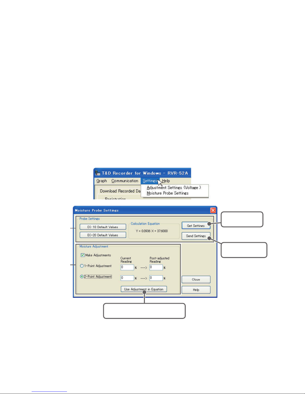
69
■ Moisture Probe Settings
If under the [Start Recording] Tab, you have selected "Measure
Moisture by Percentage" as the Measuring Mode, then here you
should set into the Data Logger the moisture percentage calculation
equation for the moisture sensor you are using.
1.
Please follow directions as found in [Communication between Data
Loggers and Computers] by connecting the RTR-57C/57U unit to your
computer and place the RVR-52A unit face down on top of it. (see P.21
for details)
2.
In the Main Window, click on the RVR-52A icon. To open the [Moisture
Probe Settings] Window, click on [Settings] in the Menu Bar and then
select [Moisture Probe Settings] from the pull down menu.
Moisture
Adjustment
Probe
Settings
[Use Adjustment in Equation]
Button
[Send Settings]
Button
[Get Settings]
Button
- Probe Settings
Select which sensor you are using, either EC-10 or EC-20 and click the
[EC-xx Default Values] Button and [Send Settings] Button for that sensor.
- EC-10 Default Values: Y = 0.0936 X - 37.6
- EC-20 Default Values: Y = 0.0695 X - 29
Page 75

70
Note
- For more details about these values, please see the User's Manual that came
with your sensor.
[Get Settings] Button
This allows you to gather the equation that is currently set in the RVR-52A
logger.
[Send Settings] Button
This sends the currently displayed moisture percentage calculation
equation to the RVR-52A logger.
- Moisture Adjustment
Before making adjustments, use the [Get Settings] Button to receive the
current settings.
By placing a check next to [Make Adjustments], it is possible to make
corrections for measurement errors that may occur.
This function allows you correct or adjust for errors in measurement values.
The Data Logger will record only the adjusted value.
Current Reading: Enter the actual measurement before adjustment
Post-adjusted Reading :
Enter the desired measurement after adjustment.
[Use Adjustment in Equation] Button
The newly adjusted equation will appear in the Moisture Percentage
Calculation Equation Area.
[Send Settings] Button
The adjusted equation will be sent to the Data Logger.
Note
- When you are carrying out adjustments and formulating equations please take
care with the settings and take personal responsibility for the process.
- We cannot guarantee that after carrying out adjustment the measuring accuracy
will improve for all measuring ranges.
- For details about Moisture Adjustment, see the [Help Menu] in the provided
software T&D Recorder for Window
s.
Page 76

71
RTR-57C/57U: Downloading Recorded Data
Here all settings and communication for RTR-57C/57U (Data
Collectors) can be carried out. Connect a Data Collector to your
computer so that communication can occur.
* For details about connecting the Data Collector(S), please see P.19 for details.
Note
- If you are using RTR-52Pt, only RTR-57U can be used.
Moreover, versions of RTR-57U prior to version 3 are not compatible. If you are
unsure of what version you have, please check the version information in the [Help]
menu under [RTR-57C/57U Version Info].
■ Collect RTR-57C/57U Data Info
1.
In the Main Window, click the icon [RTR-57C/57U] and click the
[Download Recorded Data] Tab.
[
Download Recorded Data] Tab
[Collect Data Info]
Button
2.
By clicking the [Collect Data Info] Button, communication will be started
and the data list saved in RTR-57C/57U will be displayed.
Data Collector
Contents
Page 77
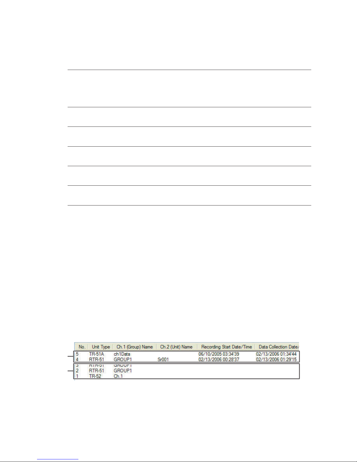
72
Data Collector Contents
No. indicates the data number (1 to 250) assigned in
the order of collection. By clicking the [No.] title
area you can change the order between
ascending and descending.
Unit Type RTR-51, etc... Indicates the type of unit, such as
RTR-51.
ch.1 (Group) Name Shows the Channel 1 Name (For RTR-5 Series
and RVR-52A it will be the Group Name).
ch.2 (Unit) Name Shows the Channel 2 Name (For RTR-5 Series
and RVR-52A it will be the Remote Unit Name).
Recording Start
Date/Time
Displays the recording start date and time for the
data gathered in the Info List.
Data Collection
Date/Time
Displays the date and time data was downloaded
from the Data Collector to Computer.
Note
- When downloading data from any RTR-5 Series or RVR-52A Unit, the Channel
Name display will automatically indicate [Group Name / Remote Unit Name].
- When using the event recorder function, the recording start time will be displayed
even if you have downloaded by specifying the download to Data Collector date and
time. For details about how to download to the Data Collector, see the User's Manual.
- After gathering data info, it will be stored until the application is closed. However, if
you do not close the application and connect to and transmit info with a different
Data Collector or manipulate data from the Data Collector Unit, the data info stored
in the application will be different from that in the Data Collector Unit. Please gather
the data information again.
- Quit collecting data info while in progress
By clicking [Quit Collecting Data Info], the collection will be stopped.
①
②
① Collection of data info has been completed. All operations are possible.
② Data downloading and deletion can be done, but data info cannot be
displayed.
Page 78
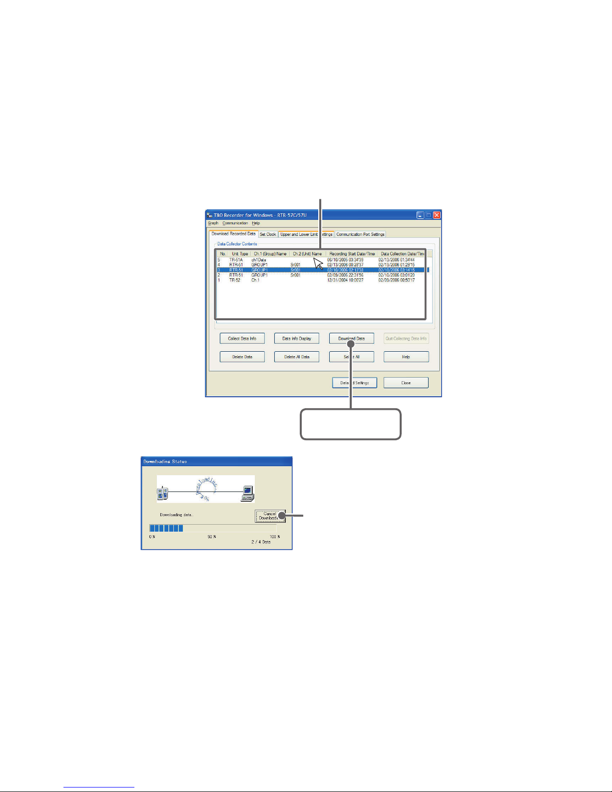
73
■ Download Recorded Data
1.
Select the data to be downloaded from the data list. By clicking the
[Download Data] Button, downloading will be started.
2.
When downloading has been completed, the graph will be displayed.
* To download several sets of data at one time, please see P.75 for
details.
[Download Data]
Button
Select data from Data Collector Contents
By clicking the [Cancel Downloading]
Button, you can stop downloading at
any time.
Note
- If you have checked [After downloading, save data in file] in the Detailed Settings,
please view the graph after specifying the file in which you wish to save the
downloaded data.
Page 79
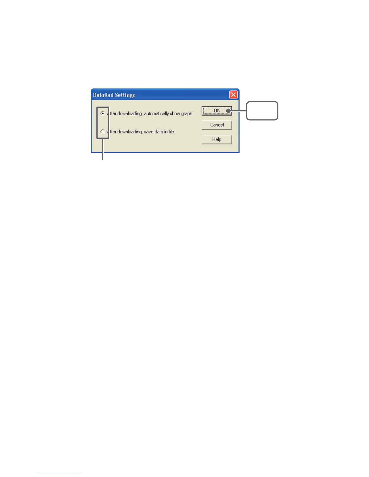
74
[Detailed Settings] Button
You can make settings for the processing of the downloaded recorded data.
Select the desired processing method and click [OK] Button to complete the
setting.
[OK]
Button
Check one
- After downloading, autmatically show graph.
- After downloading, save data in file.
Page 80
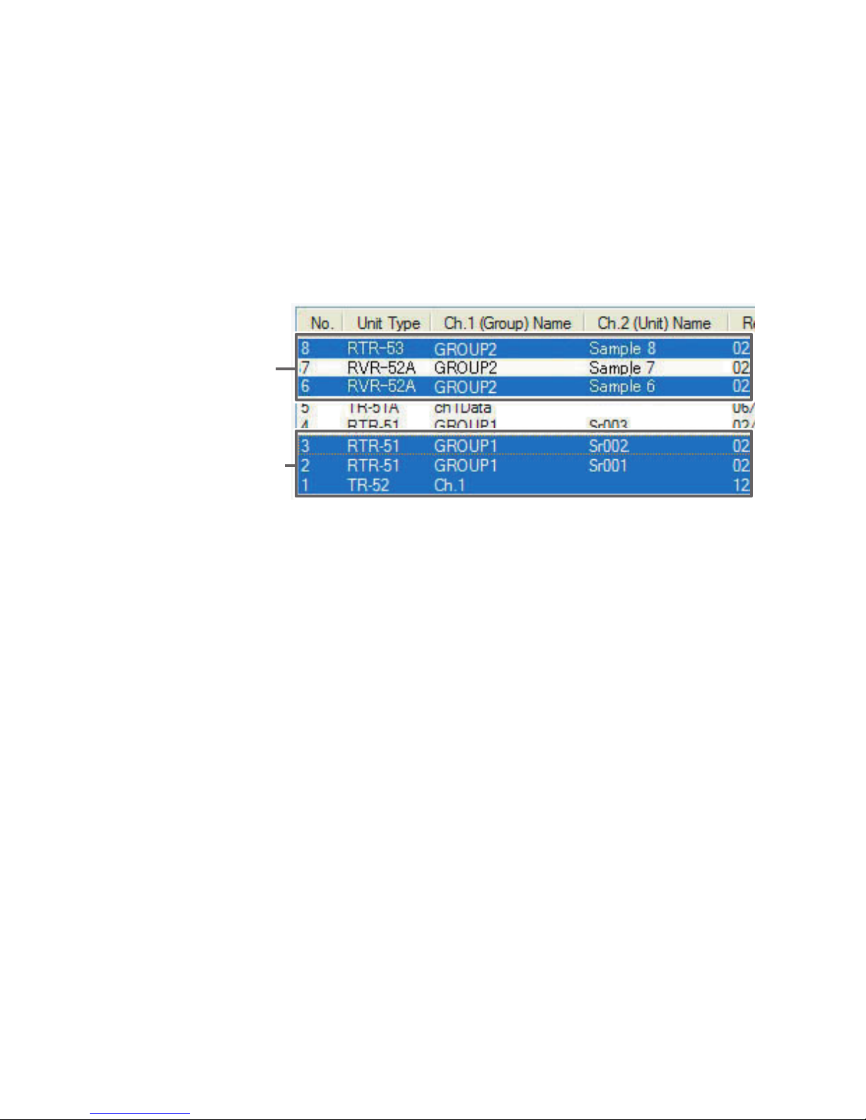
75
■ Downloading Several Sets of Data at One Time
You can make settings for the processing of the downloaded recorded
data.
1.
While holding down the <Shift> key or <Ctrl> key, click on those sets of
data you wish to download.
① Use the <Ctrl>
key to select
② Use the <Shift>
key to select
For Example
① If you wish to download files not in a row, such as No.20 and No.22,
hold down the <Ctrl> key and click on files for No.20 and No.22.
② If you wish to download files in a row, such as No.15, No.16 and
No.17, hold down the <Shift> key and click on the files for No.15 to
No.17.
2.
Click on the [Download Data] Button, and downloading will be started.
3.
When downloading has been completed, a graph will be displayed.
Note
- If you have checked [After downloading, save data in file] in the Detailed Settings,
please view the graph after specifying the file in which you wish to save the
downloaded data.
Page 81
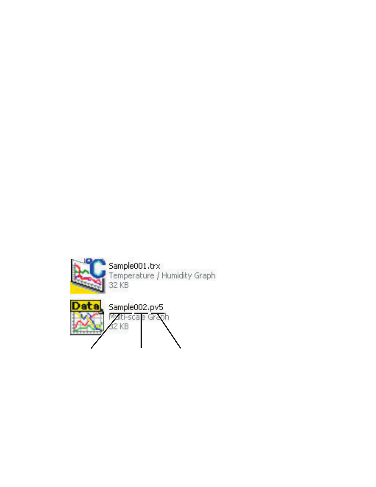
76
If you are downloading several sets of data at one time, all
operations will be carried out according to the settings made in
[Detailed Settings].
If you have checked [After downloading, automatically show graph]
and have selected several sets of data, it is possible to display the
selected data in the same graph. Moreover, in the graph display by
entering which file you wish the data to be saved, it is possible to
save several sets of data into one file.
Note
- Each kind of data is displayed in the following graphs:
Temperature/Humidity data: Temperature/Humidity Graph
Voltage/Pulse data: Multi-scale Graph
Event data: Event Viewer.
If you have checked [After downloading, save data in file] and you
have selected several sets of data, at the end of the specified file
name of every recorded data will appear the list number (No.1 →
001, No.2 → 002, No.3 → 003...)
Extension Code
.trx : Universal Thermo Recorder type file
.pv5
:
RVR-52A voltage, pulse data file
.rp7 :
RVR-52A event data file
List NumberFile Name
Page 82
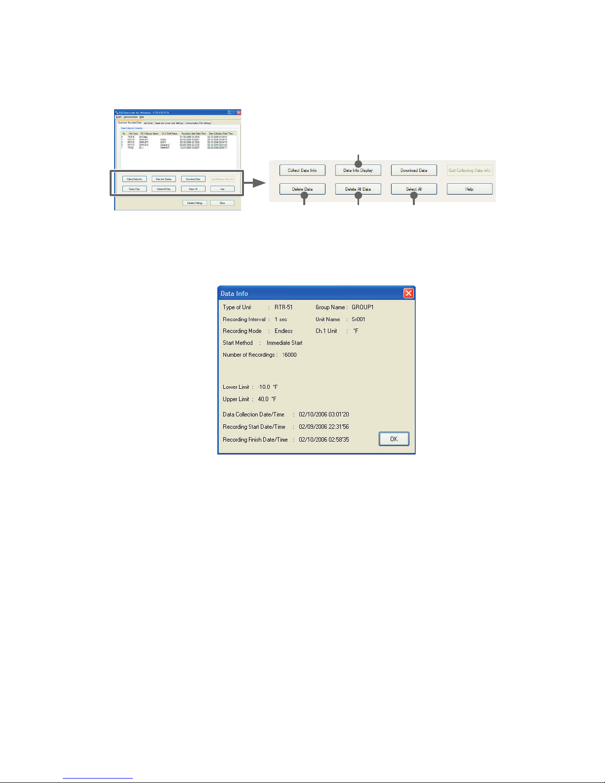
77
■
About other Buttons
(under [Download Recorded Data] Tab)
①
② ③ ④
① [Data Info Display] Button
Displays info about data for all selected data from the list.
However, info cannot be shown for event recording data.
Data Info Display
Sample
② [Delete Data] Button
Deletes selected data saved in the RTR-57C/57U from the software.
③ [Delete All Data] Button
Deletes all data saved in the RTR-57C/57U from the software.
④ [Select All] Button
Selects all data in list to be downloaded at the same time.
Page 83
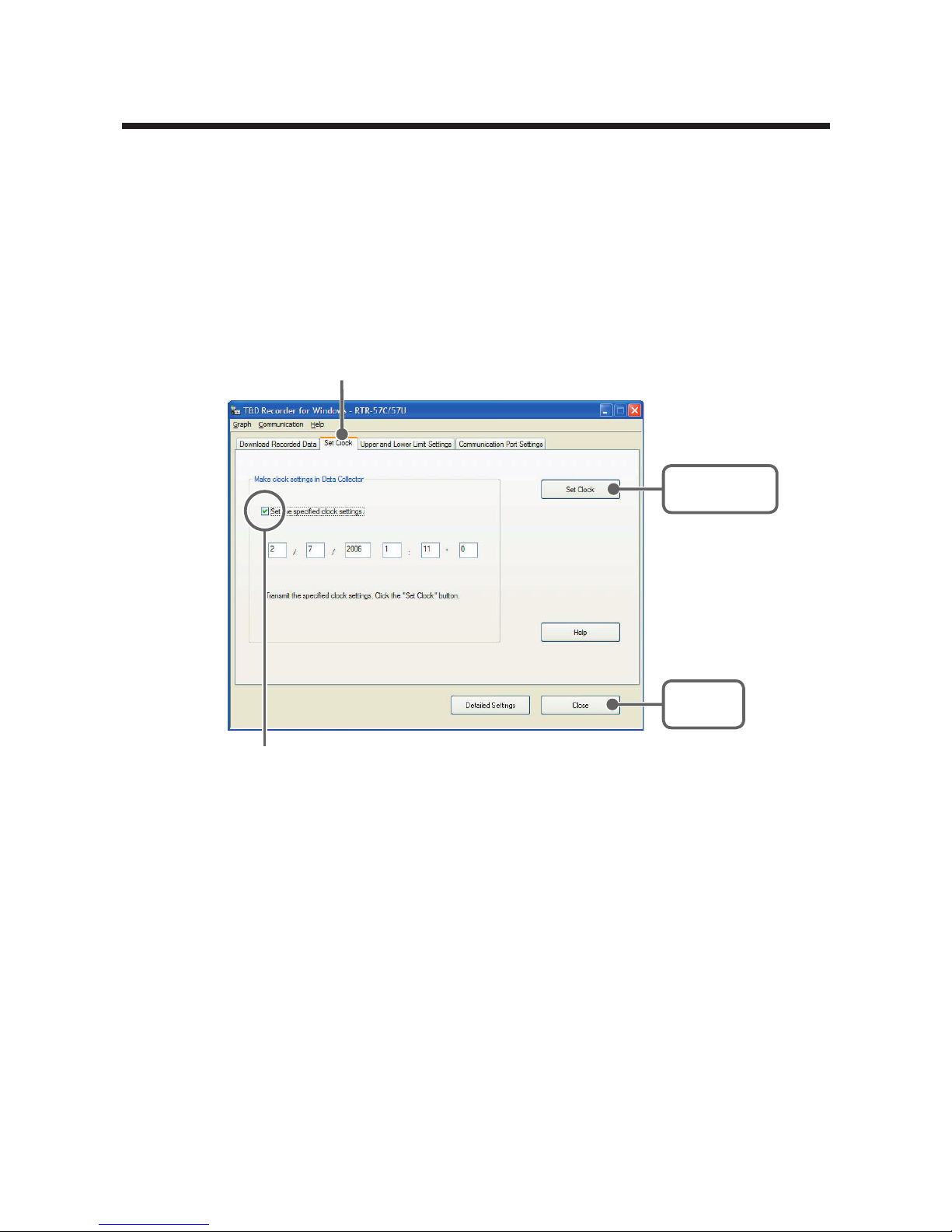
78
Setting the RTR-57C/57U Clock
1.
In the Main Window, click the icon [RTR-57C/57U].
2.
Click the [Set Clock] Tab.
3.
Select setting method and by clicking the [Set Clock] Button, the setting
will be transmitted.
4.
Click [Close] Button to complete the setting.
[Set Clock]
Button
[Close]
Button
Set the specified clock settings
- If checked : The date/time you enter will be set as the date / time in
the
RTR-57C/57U.
- If not checked :The current date/time of your computer will be set
as the date/time in the RTR-57C/57U.
[Set Clock] Tab
Page 84
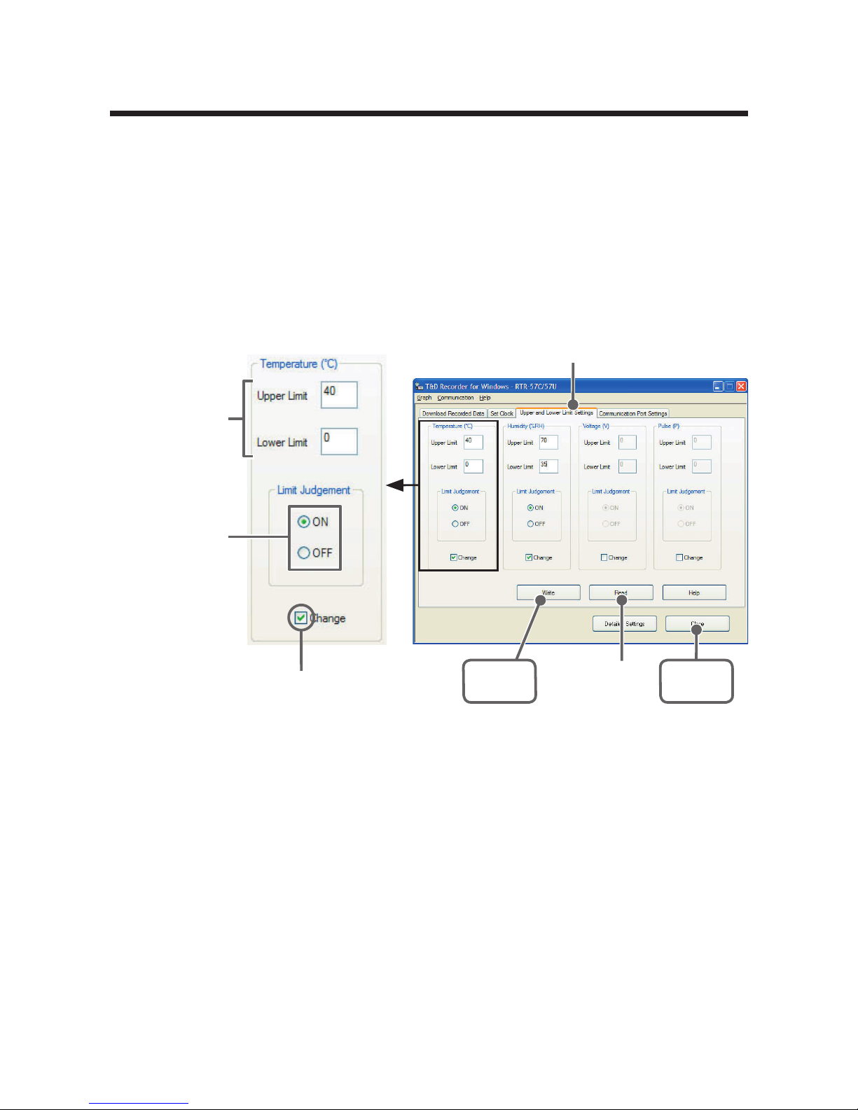
79
RTR-57C/57U : Upper and Lower Limits
Setting is directly possible in RTR-57C/57U Main Units version 2 or
higher. The version can be confirmed in [Help] - [Main Unit Version
Info].
* Please See the Help Menu in RTR-57C/57U for details.
1.
In the Main Window, click the icon [RTR-57C/57U].
2.
Click the [Upper and Lower Limit Settings] Tab, and check the
<Change> box.
[Upper and Lower Limit Settings] Tab
Check [Change]
[
Close]
Button
[Write]
Button
Enter
values
Check
[Read]
Button
3.
After entering the upper and lower limit values, check [ON] and by
clicking the [Write] Button, the information will be transmitted.
- ON : Judges whether recorded data is within the set range when
RTR-57C/57U has downloaded the recorded data.
- OFF : Judgment isn't carried out even if upper and lower limits have
been set.
4.
Click [Close] Button to complete the setting.
Page 85

80
Note
- If upper and lower limit settings have been made in the RTR-5 Series or RVR-52A
Loggers, those settings will take precedence.
- These settings can be made for RTR-57 Series Version 2 and above. If you are
unsure of what version you have, please check the version information in the
RTR-57 Series [Help] menu.
- For more details, see the [Help] menu in the T&D Recorder for Windows software.
[Read] Button
If you wish to view the current settings, click the [Read] Button.
Page 86
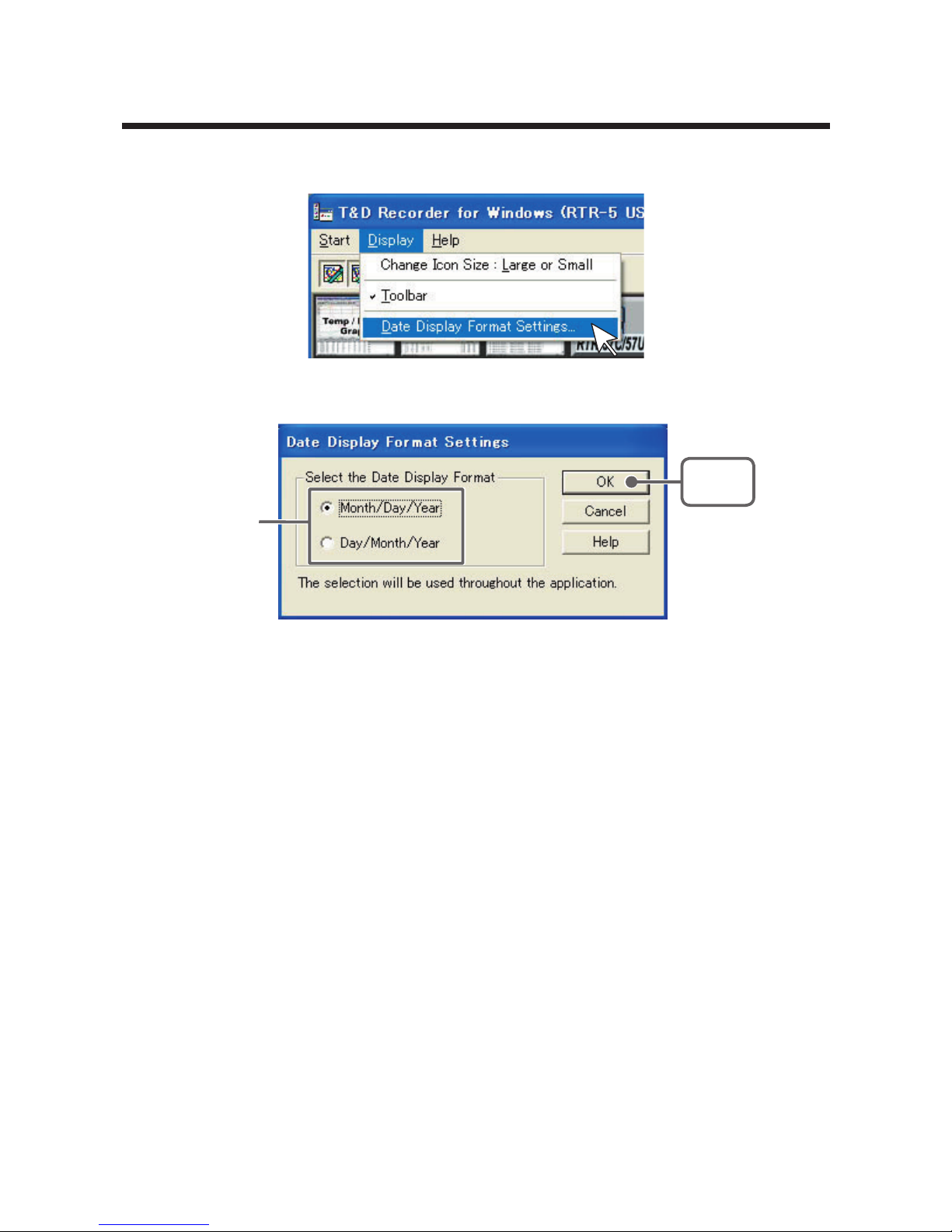
81
Setting the Date Display Format
1.
In the [Display] Menu, select [Date Display Format Settings].
2.
Check either [Month / Day / Year] or [Day / Month / Year].
Check
one
[OK]
Button
3.
By clicking the [OK] Button, the setting will be completed.
Note
- The date format chosen will be applicable for all sections of the software including
graphs and setting displays.
Page 87

82
Page 88
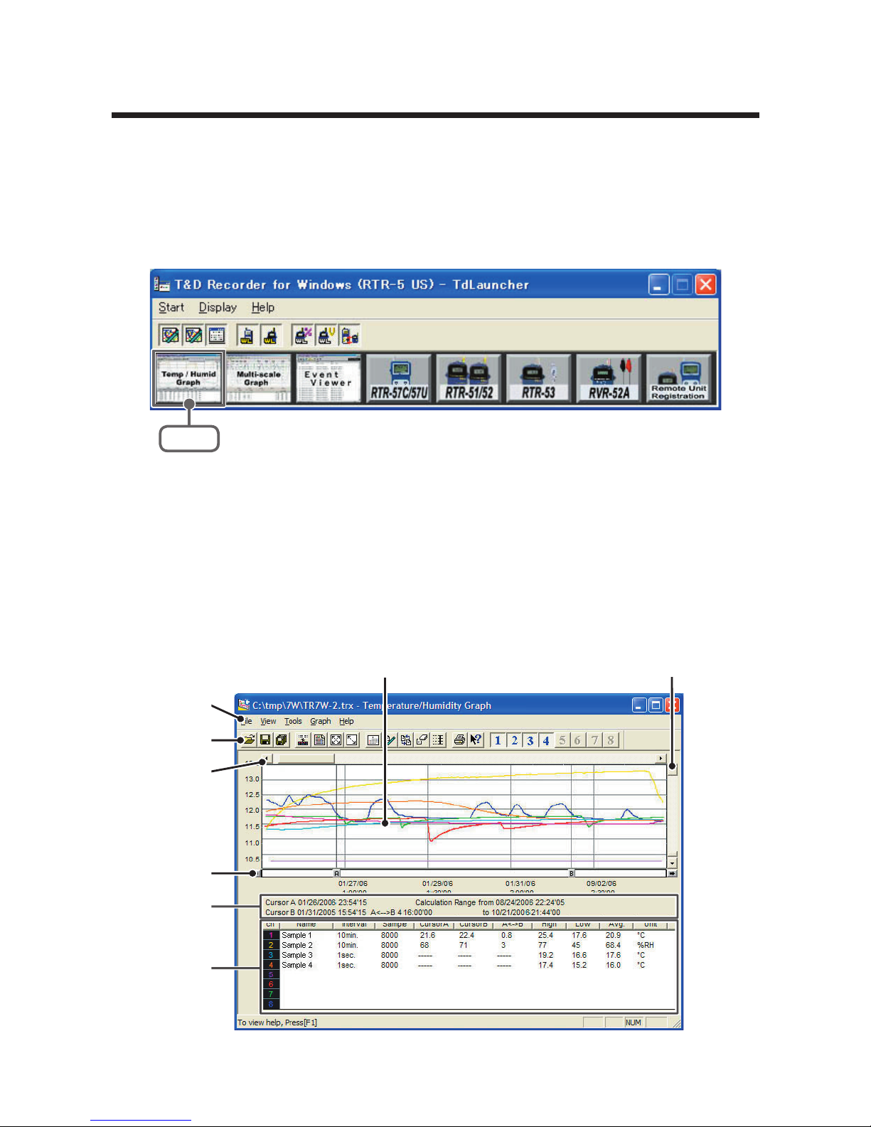
83
Temperature/Humidity Graph
Here operations can be carried out to view in graph form the
temperature and humidity data recorded by RTR-5 Series Data
Loggers.
Open the Graph display by clicking the icon [Temp/Humid Graph] in
the Main Window.
Click
Note
- In the Main Window or in the Settings/Communication Display of [RTR-57C/57U],
[RTR-51/52], or [RTR-53], select the [Temp/Humid Graph] from the [Start] menu to
open the graph.
- If you have clicked [Display the graph after downloading recorded data], the graph
will automatically open.
■ Display Names and Functions
⑧
①
②
⑤
③
④
⑦
⑥
Page 89
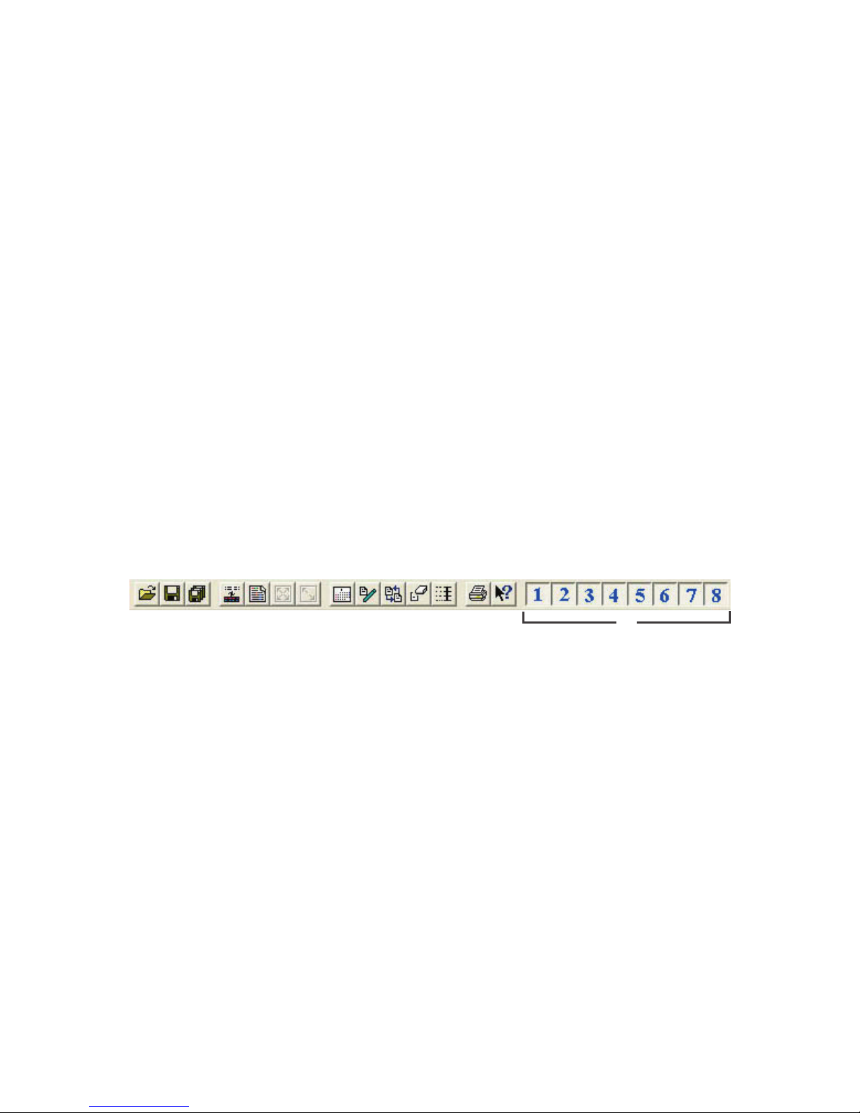
84
① Graph Area
The area in which the Graph is displayed. The horizontal axis shows time and
the vertical axis shows temperature / humidity data.
②
A / B Cursor Movement Buttons and A / B Cursor Buttons
By clicking one of the arrow buttons at either side of the bar, you can
simultaneously move the A/B cursors. Click and drag the A or B Button to
move the cursor to the left or right.
③ A and B Cursor Position Information
The approximate date and time for the A and B cursor positions and the time
difference between the A cursor and the B cursor is displayed.
④ Channel Info List Display
Displays data information for Channels 1 to 8. The list contains the following info:
Channel Name, Recording Interval, Amount of Data, Data Values for AB Cursor
positions, the High, Low and Average values for the set calculation range.
⑤ Menu Bar
Click on the desired menu in the Menu Bar to set or display each function
from which you can choose from an array of commands.
⑥ Toolbar
Buttons appear for frequently used commands.
① Open File
② Overwrite Data
③ Save Data as...
④ Change Data Display Colors
⑤ Data Display ON/OFF
⑥ Return to Original Size
⑦ Step-by-Step to Original
⑧ Set High, Low, Avg. Calculation Range
⑨ Edit Recording Conditions
⑩ Re-order Channels
⑪ Erase Selected Channels Data
⑫ Vertical Axis Settings
⑬ Print
⑭ Help
⑮ Hide / View Channels
② ⑤ ⑦ ⑫
① ③ ⑥④ ⑪⑧ ⑨ ⑩ ⑬⑮⑭
⑦ Horizontal Gauge Bar and Button for Moving Horizontal Axis
By dragging the gauge you can move left and right to the data you want to be
displayed. The time axis moves by clicking these arrow buttons.
⑧
Vertical Gauge Bar and Button for Moving Vertical Axis
By dragging the gauge you can move up and down to the data you want to be
displayed.
The vertical axis moves up or down by clicking these arrow buttons.
Page 90
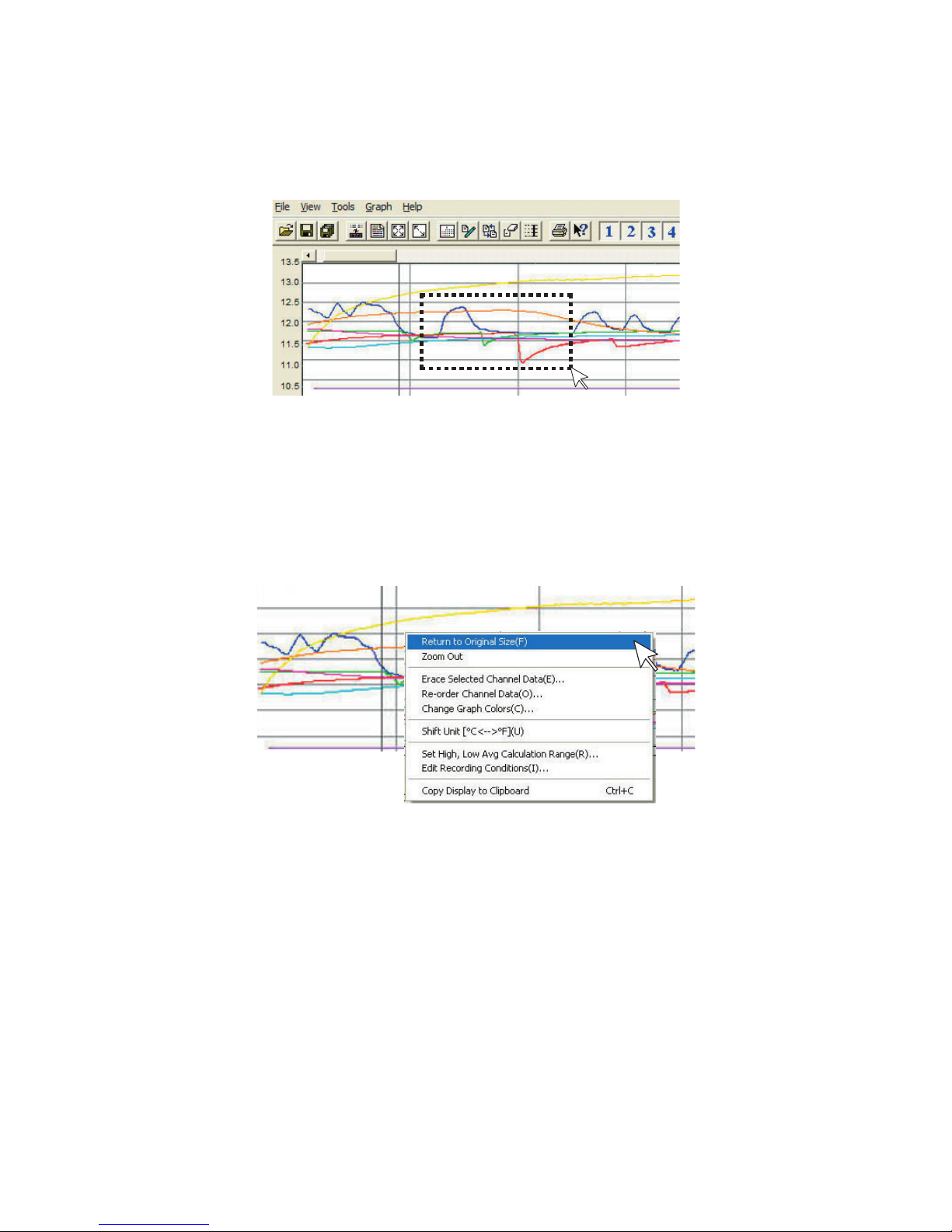
85
■ Zooming In and Out on the Graph
Zoom in Using the Mouse
With the left Button drag the mouse to outline the area you want to zoom in on.
Menu Display Using the Mouse
By right clicking on the graph, the Menu will be displayed. With [Return to
Original Size] or [Step-by Step Return to Original] you can return both the
vertical and horizontal axis back to show the entire graph.
- These operations can be carried out via commands in the [Graph] Menu or
by clicking icons in the Toolbar.
About the Horizontal Axis
The entire graph shows in the horizontal axis the nearest data to the recording
start time and the latest data nearest the recording finish time for each
channel 1 to 8. This represents the full scale of the horizontal axis.
About the Vertical Axis
The entire graph shows in the vertical axis the lowest possible measurement
value and the highest possible measurement value for channels 1 to 8. This
represents the full scale of the vertical axis.
Page 91
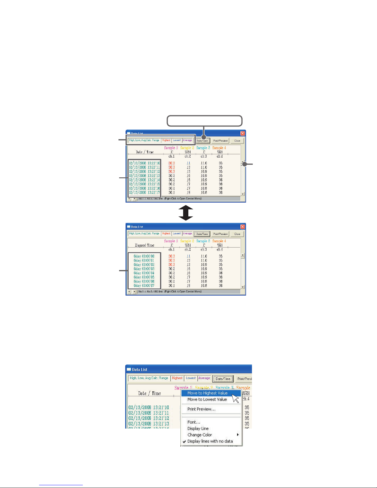
86
■ Data List Display
[Date / Time] Button
By clicking this Button, you can shift the display between the recorded date
and amount of elapsed time since recording started.
①
[
Date / Time] Button
②
Recorded Date
Display
Elapsed Time
Display
① This is a list of the data that was displayed in graph form. The highest value is in RED,
lowest is in BLUE, and the average is in PINK.
② Scroll Bar: By dragging it up and down you can move to the data you want.
Menu Display Using the Mouse
By right clicking on the list, the Menu will be displayed.
Page 92
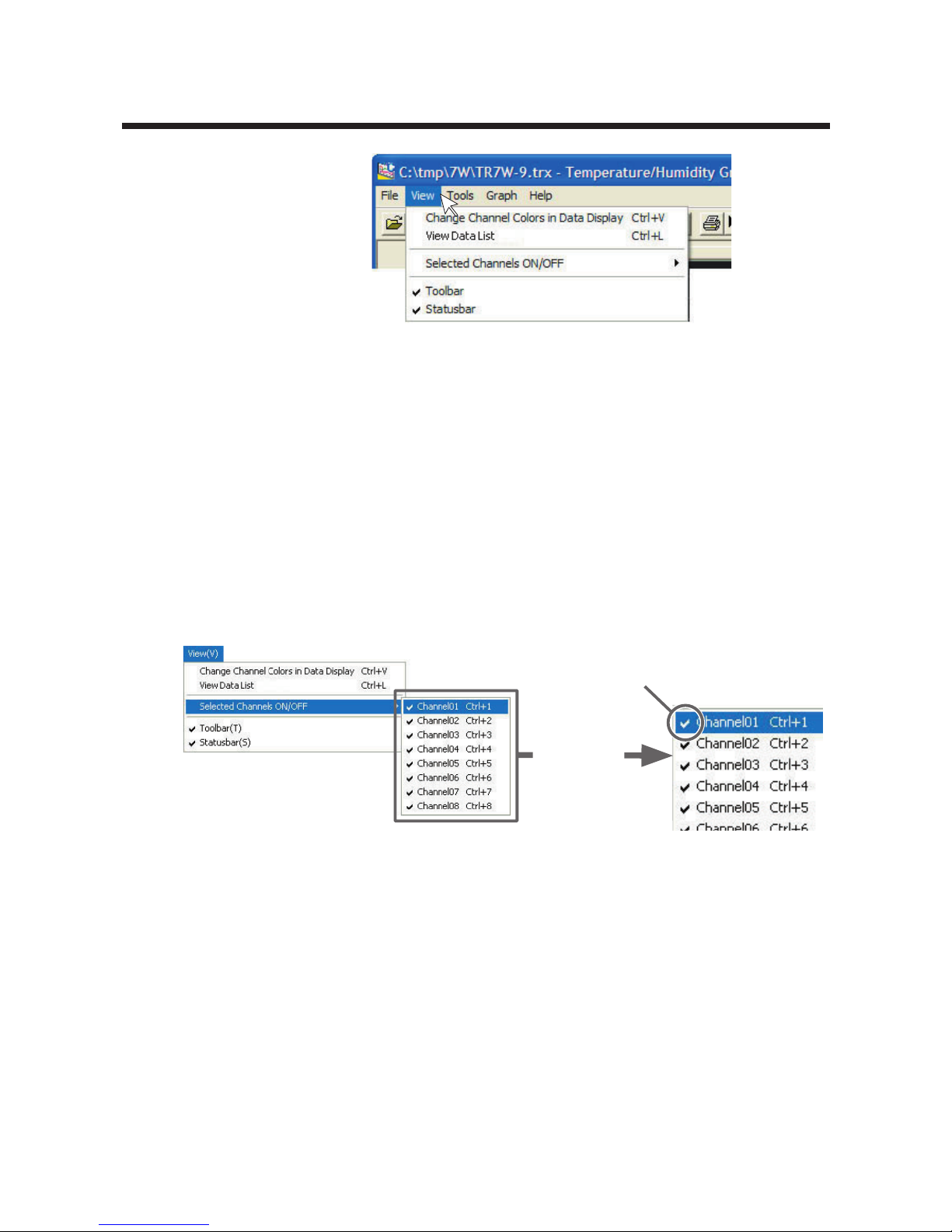
87
Editing the Graph: [View] Menu
[View] Menu
■Changing graph display colors:From the [View] Menu
You can change the letters used in the data list display for each
channel between monochrome and channel color.
■Selected Channels ON/OFF: From the [View] Menu
1.
The channel numbers are displayed in the pull down menu of [Selected
Channels ON/OFF].
2.
Check the channel numbers you wish to display.
Check
Enlarged
* By clicking a Channel Number in the Toolbar, you can carry out the
same operation.
Page 93
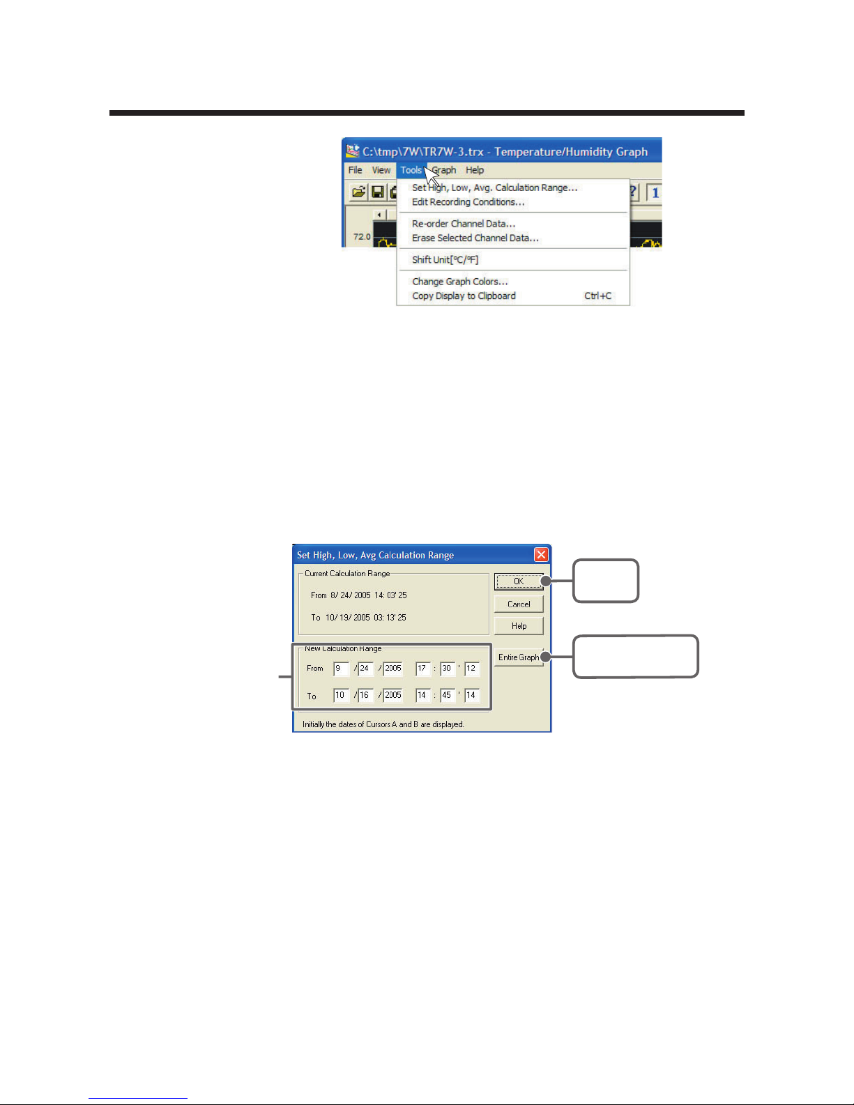
88
Editing the Graph: [Tools] Menu
[Tools] Menu
■ Setting High, Low, Average Calculation Range:
From the [Tools] Menu
1.
Set the calculation range in the [Set High, Low, Avg. Calculation Range]
box.
2.
By clicking the [OK] Button, the high, low, average calculation range of
each channel data will be changed. On the graph display, the calculation
range that you have set will be displayed.
[Entire Graph]
Button
[OK]
Button
Enter the
numerical value
[Entire Graph] Button
To make the Calculation Range that of the Entire Graph, click the [Entire
Graph] Button. The dates and times in the [Set High, Low, Avg.
Calculation Range] box will be displayed as those of the entire graph.
Set by using the AB Cursors
In the Graph Display, open the [Set High, Low, Average Calculation
Range] box adjusting the AB cursors to the desired start and end
positions. The dates and times of those cursors will be displayed
automatically.
Page 94
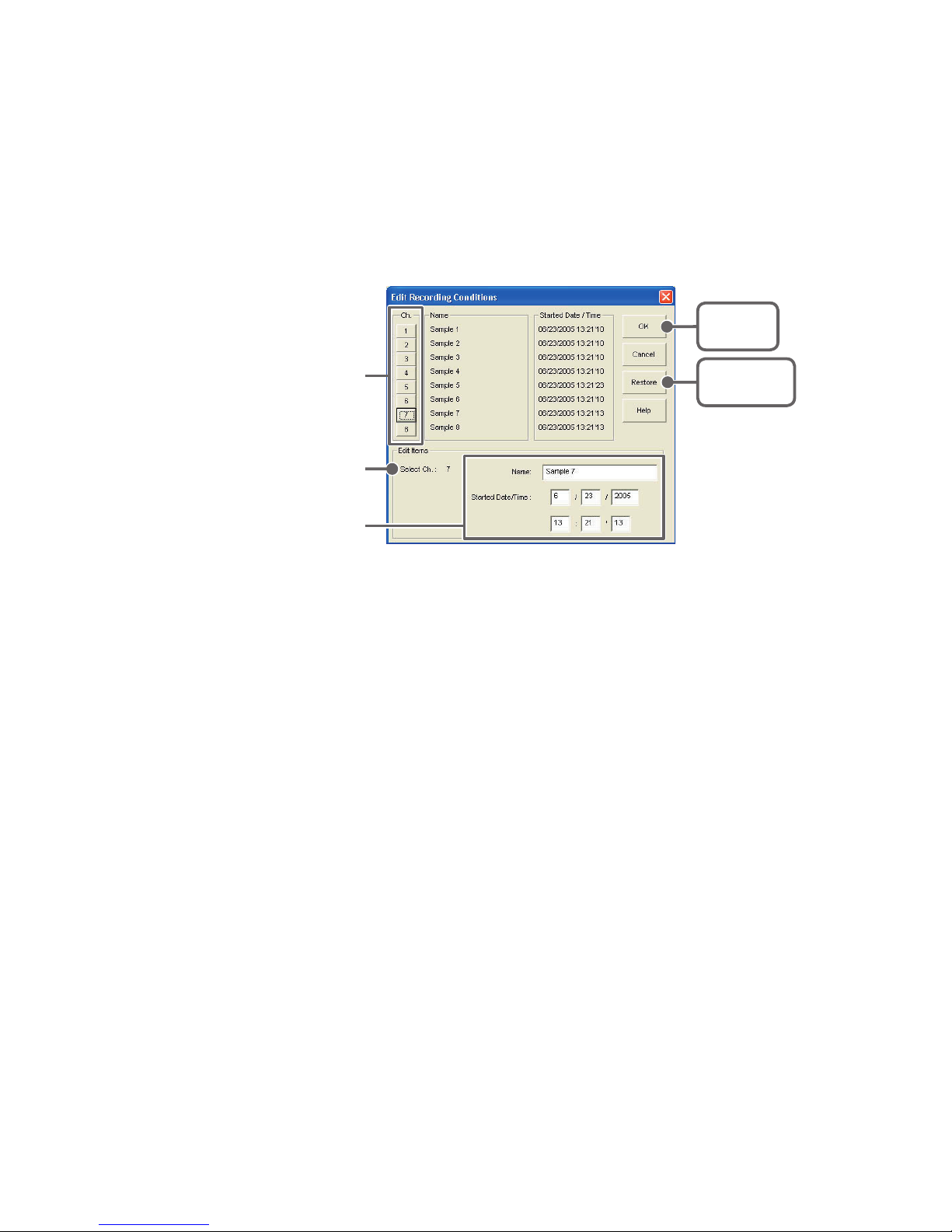
89
■Editing Recording Conditions : From the [Tools]
Menu
1.
By clicking the [Ch.] Button you wish to change, the information for that
number will be displayed in the "Edit Items".
2.
By clicking the [OK] Button after changing, the setting will be completed.
[OK]
Button
[Restore]
Button
Enter letters and
numerical values
Channel Number
The selected
channel number
- Name : Up to 32 letters can be entered.
- Starting Date/Time : The month, day, year,
hour, minute and second
can be changed.
Note
- If you wish to continue to change other channels, repeat the process as in 1.
- The [
Restore] Button is effective only during the setting, and cannot return to the
condition it was after the [OK] Button has been clicked.
Page 95
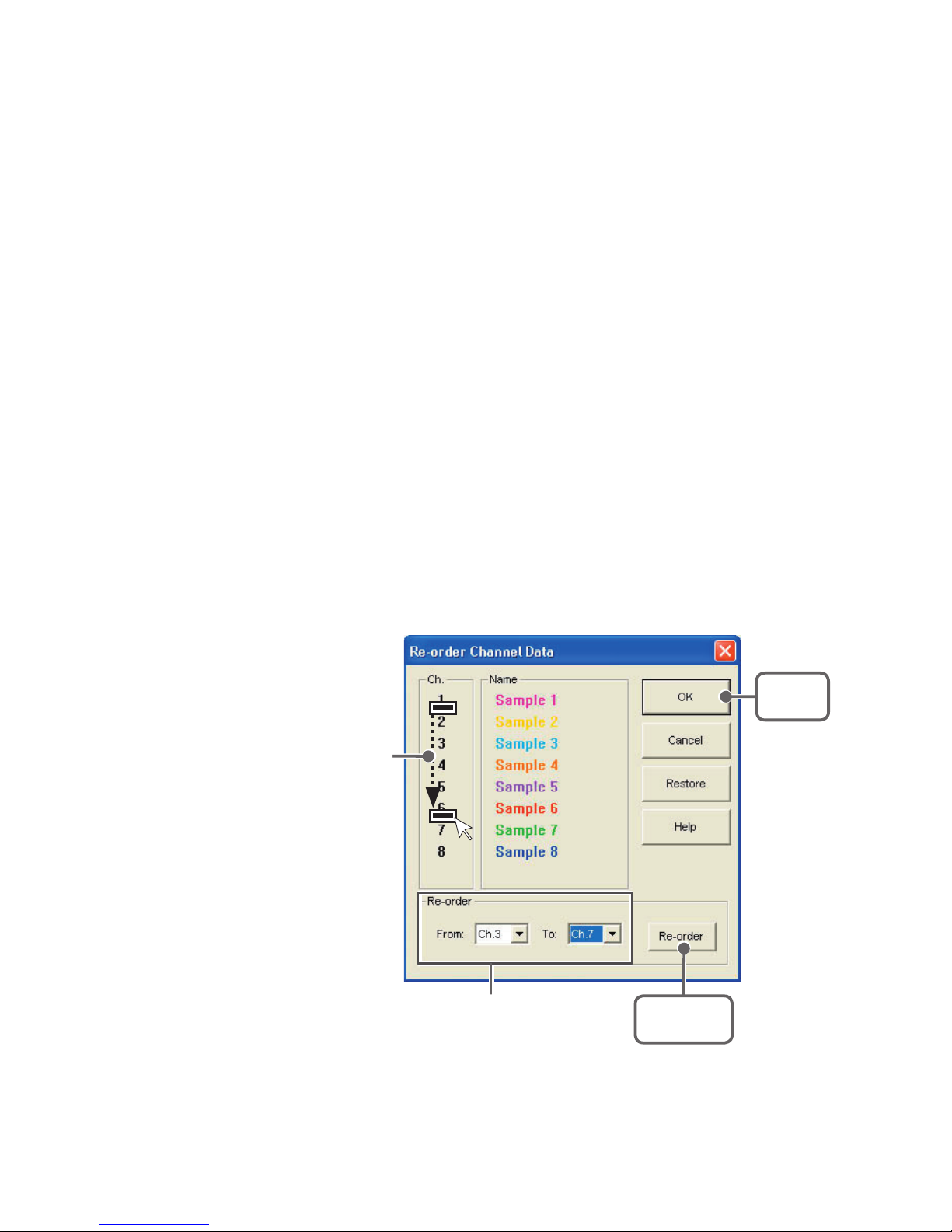
90
■ Re-ordering Channel Data: From the [Tools]
Menu
There are two ways for re-ordering.
- Move by dragging the channel number
- Move by selecting the channel number
【Move by dragging the channel number】
Click on the channel of data you wish to move and drag and drop it to the
desired new channel position.
【Move by selecting the channel number】
1.
Enter in From: _, the Channel number you wish to move from, and enter
the Channel number to which you want to move in
To:
_.
2.
By clicking the [Re-order] Button, the movement will be completed.
Note
- The [Restore] Button is effective only during the setting, and cannot return to the
condition it was by clicking the [OK] Button.
[Re-order]
Button
[OK]
Button
If you wish to move Ch3. to Ch7.
simply set From → Ch3, To → Ch7.
Drag and drop the
channel number to the
desired new position.
Page 96
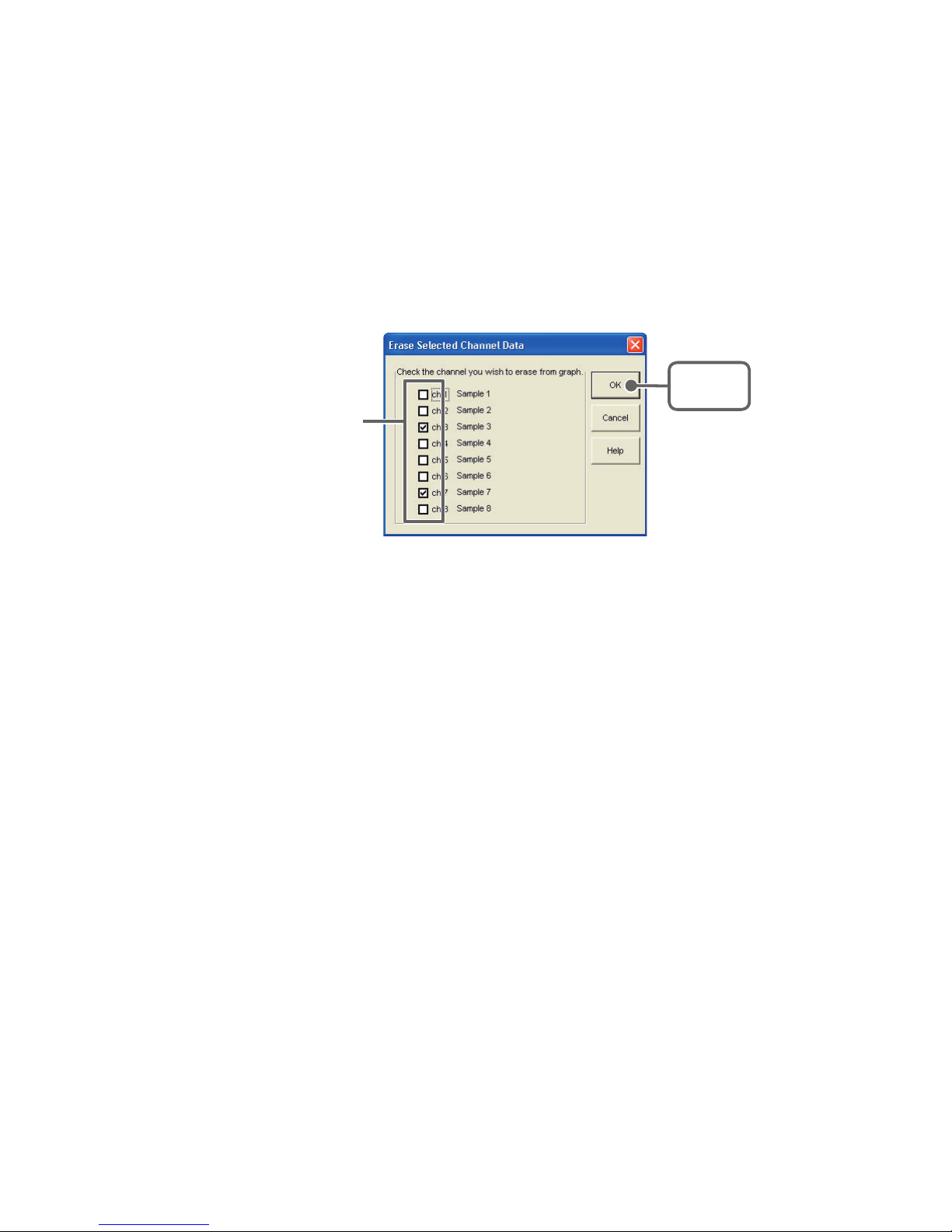
91
■Erasing Selected Channel Data:From the [Tools]
Menu
1.
Put a check on the channel number you wish to erase.
2.
By clicking on the [OK] Button, the deletion will be completed.
[OK]
Button
Put a check on the
check box
■ Shifting Unit (℃ / ゜F): From the [Tools] Menu
By clicking on [Shift Unit (℃ / °F)], you can automatically change
the temperature unit scale in the graph display and in the channel
info list.
■ Changing Graph Colors: From the [Tools] Menu
1.
Click the channel number of which you wish to change the color.
2.
By clicking each Button, color samples will be displayed. Choose the
color you want and click the [OK] Button.
3.
After confirming the color, by clicking the [OK] Button the change will be
completed.
Page 97
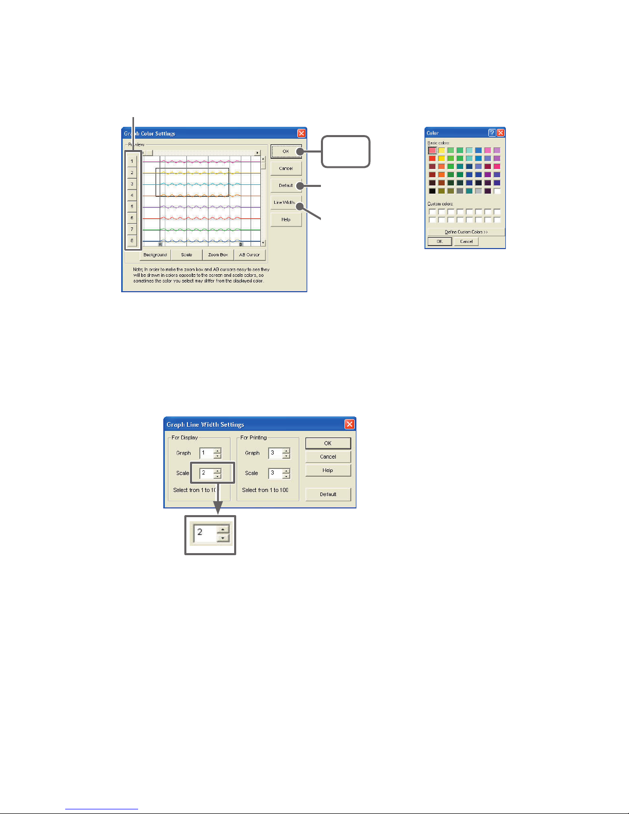
92
Color Sample
[Channel No.] Button
[OK]
Button
[Line Width...]
Button
[Default]
Button
Note
- By clicking the [Return to Default] Button, you will return to the color settings when
the software was opened.
[Graph Line Width Settings] Button
Change the width of the data lines and the scale lines.
Every time you click on
▲ --------the numerical value gets larger,
▼ --------the numerical value gets smaller.
■ Copying Display to Clipboard:From the [Tools]
Menu
By clicking [Copy Display to Clipboard], you can copy the currently
displayed window to the clipboard and make use of the graph
pasting in other software.
Page 98
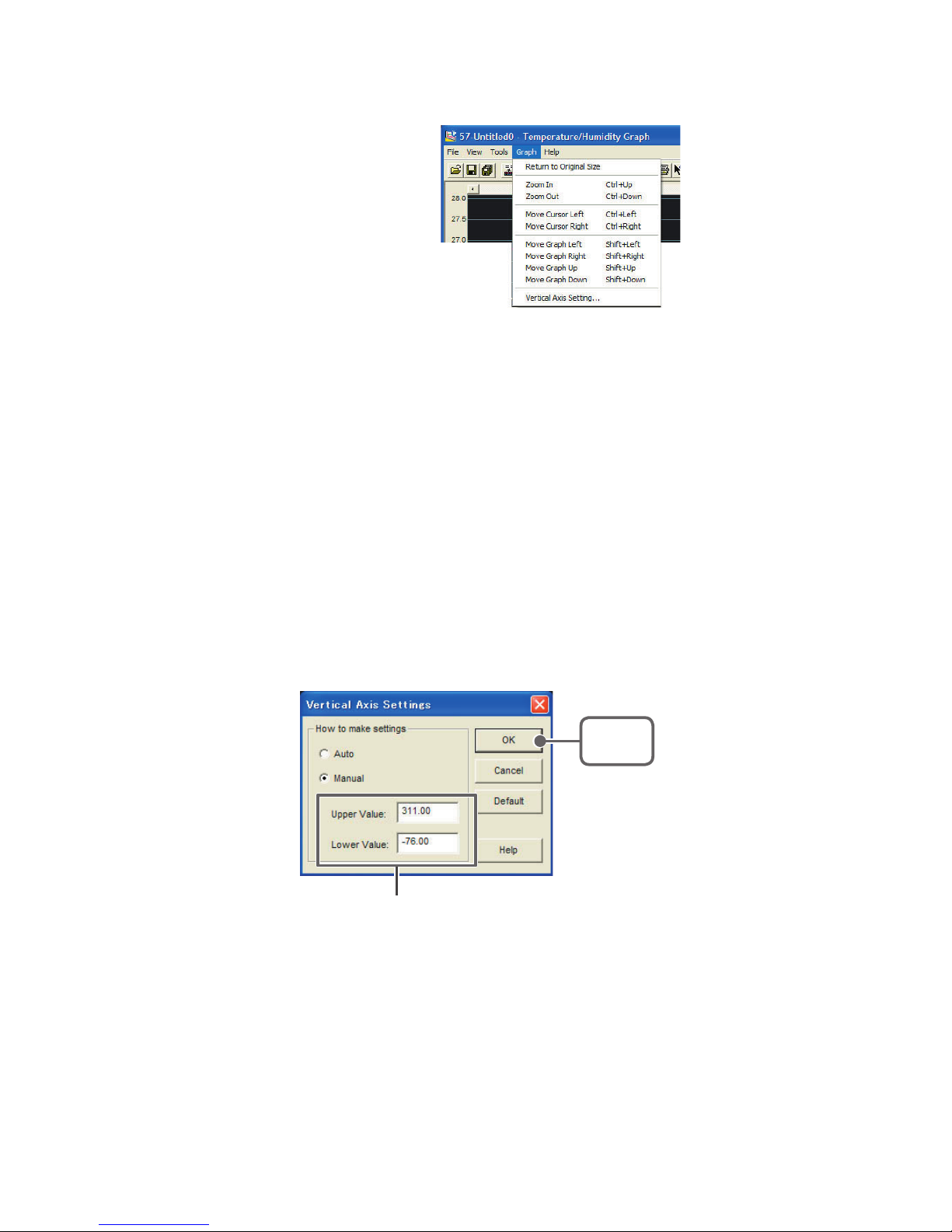
93
■ Graph:From the [Graph] Menu
[Graph] Menu
Return to Original Size
Return from zooming in on one part of data
Zoom In / Zoom Out
Zooms in or out one step at a time
Move Cursor Right / Left
Simultaneously move the AB Cursors to the right or left.
Move Graph Right / Left
Move the Graph Display to the right or left.
Move Graph Up / Down
Move the Graph Display up or down.
Vertical Axis Settings (AUTO in Default Settings)
Set the vertical axis scale (temperature)
Enter the range of the
vertical axis scale.
[OK]
Button
- AUTO: The vertical axis will automatically be changed according to the
values of the data.
- MANUAL: You can set the upper and lower values of the vertical axis scale.
Page 99
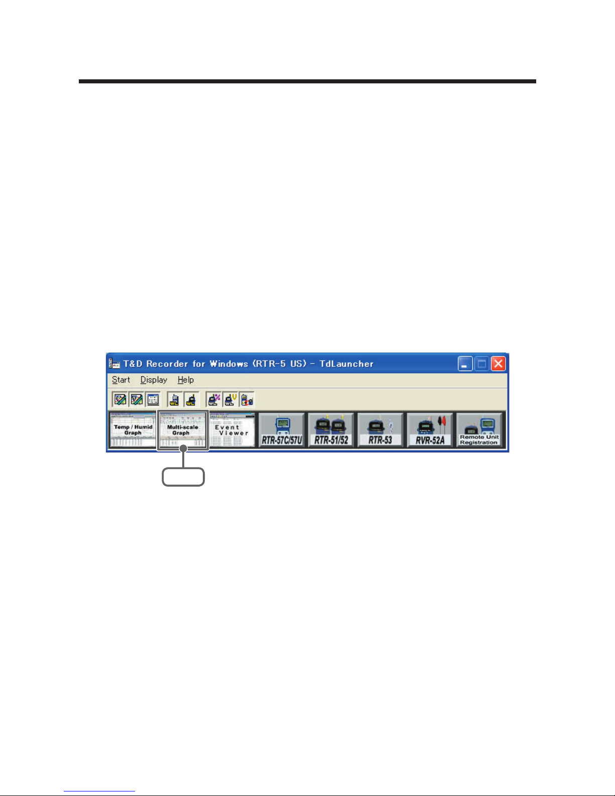
94
Multi-scale Graph
This software, Multi-scale Graph is designed to allow you to view
simultaneous display of graph channels with different scales such
as temperature, humidity, voltage, pulse and moisture data in one
window.
The [Multi-scale Graph] program will read data files that have been
created from the downloaded data from the loggers and to help you
analyze that data will allow you to create graphs, data lists, text files
and print data. It is also possible to scroll across the graph and
make scale settings for each channel.
Note
- For detailed information about the compatible data file types for the [Multi-scale
Graph], see the Multi-Scale Help Menu.
Open the Multi-scale Graph by clicking the [Multi-scale Graph] icon
in the Main Window.
Click
Note
- In the Main Window or in the Settings/Communication Display of RTR-57C/57U, or
RVR-52A, select [Multi-scale Graph] from the [Start] menu to open the graph.
- If you have clicked [Display the graph after downloading recorded data], the graph
will automatically open.
Page 100
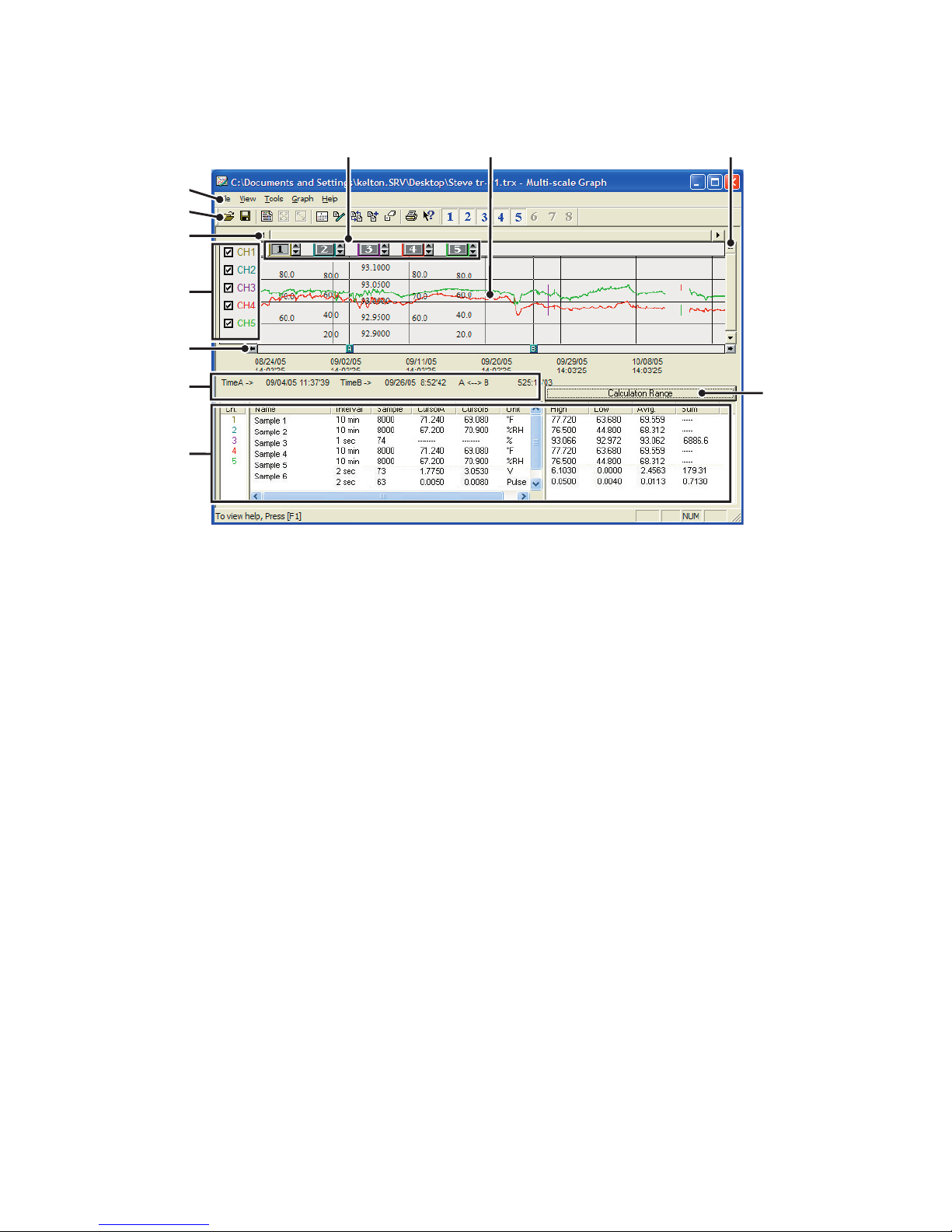
95
■ Display Names and Functions
③
⑦
⑤
①⑥ ⑩
⑧
②
⑨
⑪
④
① Graph Area
The area in which the Graph is displayed. The horizontal axis shows time
and the vertical axis shows the unit of data after having used the
conversion equation to convert the original measured voltage.
② A / B Cursor Movement Buttons and A / B Cursor Buttons
By clicking one of the arrow buttons at either side of the bar, you can
simultaneously move the A/B cursors. Click and drag the A or B Button to
move the cursor to the left or right.
③ A and B Cursor Position Information
The approximate date and time for the A and B cursor positions and the
time difference between the A cursor and the B cursor is displayed.
④ Channel Info List Display
Displays data information for Channels 1 to 8. The list contains the
following info: Channel Name, Recording Interval, Amount of Data, Data
Values for AB Cursor positions, the High, Low and Average values for the
set calculation range.
⑤ The Vertical Axis Display ON/OFF
Shift the vertical axis scale display ON/OFF.
 Loading...