

Page 1
User’s Manual
Thank you for purchasing our product.
Carefully read this instruction manual
before using this unit.
2003.7 16004264060
Cop y r ight 20 0 1 -2003 T & D Corpo r a tion. A l l right s reserve d .
Page 2
●
All rights of this User’s Manual belong to T&D Corporation. It is prohibited to
use, duplicate and / or arrange a part or whole of this User’s Manual without
the permission of T&D Corporation.
●
Microsoft and Windows are registered trademarks of Microsoft
Corporation USA and are binding in the USA and all other countries.
Company names and product names are trademarks or registered
trademarks of each company.
●
Specications, design and other contents outlined in this manual are
subject to change without notice.
●
On screen messages in this manual may vary slightly from the actual
messages.
●
Please notify the shop where you purchased this product or T&D
Corporation of any mistakes, errors or unclear explanations in this manual.
T&D Corporation accepts no responsibility for any damage or loss of
income caused by the use of our product.
●
This product has been designed for private or industrial use only. It is not for
use in situations where strict safety precautions are necessary such as in
connection with medical equipment, whether directly or indirectly.
●
We are not responsible for any malfunction or trouble caused by the use of
our product or by any problem caused by the use of measurement results
of our unit. Please be fully aware of this before using our product.
●
Some of our products, which come under the category of strategic goods in
foreign trade law, need the permission of the Japanese government to be
exported outside of Japan.
●
This User’s Manual cannot be reissued, so please keep it in a safe place.
●
Please read the warranty and provisions for free repair carefully.
ⅰ
■ Notices about this User’s Manual
In order to properly use this product, please carefully read this manual before
using.T&D Corporation accepts no responsibility for any malfunction of and /
or trouble with this product or with your computer that is caused by the improper
handling of this product and will deem such trouble or malfunction as falling
outside the conditions for free repair outlined in the attached warranty.
ⅱ
To ensure safety be sure to obey all of the following
warnings.
The following items should be strictly obeyed for the safe usage of this unit,
and for protecting yourself and other people from bodily harm and/or damage
to property. To ensure the proper use of our product, please read the following
carefully and fully understand the contents.
■ Explanation of Symbols
Explanation of Warning Symbols
DANGER
Th e se ent r ies ar e a c ti ons th at a bs olu t el y u n der no
circumstance should be taken. The taking of such an action
may cause serious personal physical damage or death.
These entr ies are actions that if taken may lead to physical
injury or damage to persons or things.
Explanation of Picture Symbols
Denotes an important warning or caution. Near the symbol will
appear another symbol giving details.
(EX: stands for CAUTION AGAINST ELECTRIC SHOCK)
Denotes a forbidden action. Inside or near the symbol will appear
another symbol giving details.
(EX: stands for DO NOT TAKE APART)
Denotes an action that you must take. Near the symbol will
appear another symbol giving details.
(EX: stands for PULL POWER PLUG OUT FROM OUTLET)
Safety Precautions and Instructions
CAUTION
Page 3
ⅲ
DANGERS
Do not use this unit in wet or humid places, such as a bathroom.
Do not take apart, repair or modify the main unit. Doing so may
cause re or electrocution.
Be sure to follow the warnings and notices about use from your
PC maker when installing and using this unit.
Store RTR-57C main units, batteries and communication cables
out of the reach of children. It is dangerous to touch or swallow
batteries.
Connecting a communication cable that is connected to a PC or
a data logger to the telephone cable may cause re or damage.
If water or a foreign body enters in this unit, turn the power off
and remove the ba tteri es. Continued u se may caus e re or
electrocution.
If a ny smo ke or st rang e sm el ls a re emitted from t he u ni t,
imm ediat ely t ur n the po wer OFF and r emove the batt er ies.
Continued use may cause re or electrocution.
Do not d rop the unit, or ex pose the unit to a st rong imp act.
If that happens to the unit, immediately turn the power OF F
and remove the ba tteri es. Continued u se may caus e re or
electrocution.
ⅳ
Do not put your ngers or foreign matter into the communication
port.
Do not use batteries other than specied. Doing so may cause
re or damage.
Battery life depends on the kind of the batteries, measurement
environment, communication frequency, ambient temperature,
and battery quality.
This unit is not water-resistant. If the unit gets dirty, wipe it with
a clean cloth and a mild detergent.
If the unit will not be used for period of time, for safety reasons
please remove the battery. If left in the unit, it may leak and lead
to malfunctioning.
Battery terminals may provide insufcient contact due to age or
vibration. This may lead to data loss.
Do not use an AC adaptor other than specied. Doing so may
lead to re or damage.
Co n den s ati o n ma y o c cur if t he u nit is m ov e d f r om o ne
envi ronment to another wher e the differen ce in temperature
is great. Use t he unit in an environmen t where the a mbient
temperature is from -10 to 60℃ and the humidity is 90% RH (no
condensation) or less.
CAUTIONS
Page 4

ⅴ
Do not use the unit in places such as listed below. It may cause
electrocution, re or have adverse effects on the unit or your PC.
●
In places exposed to direct sun light.
The inside temperature of the unit will rise and may cause re, damage
or deformation.
●
In areas exposed to strong magnetic elds.
It may cause damage.
●
In places exposed to water leakage.
It may cause damage or electrocution.
●
In areas exposed to static electricity.
It may cause damage.
●
In areas exposed to vibration.
It may cause an injury, damage, and/or insufcient contact.
●
In places which are not at.
It may lead to the unit being dropped or falling and cause injury or
damage.
●
In places exposed to re or heat.
It may cause damage or a change in shape.
●
In places exposed to excessive smoke, dirt and dust.
It may cause damage.
Do not expose the unit to harmful gases or chemicals. It may
cause corrosion and/or other danger to the unit and to people
handling the unit.
To prevent damage to the unit from static electricity, remove
static electricity from your body by touching metal around you
(door knob, window frame) before touching the unit.
Static electricity may cause not only damage to the unit, but
may cause breaks in or a loss of data.
CAUTIONS
ⅵ
Page 5

ⅶ
Table of Contents
Introduction
Safety Precautions and Instructions......................
ⅱ
About Data Collector RTR-57C .............................. 1
Contents of Package
.............................................. 4
Part Names and Functions
..................................... 5
Getting Ready
Installing the Batteries ...........................................
9
Switching the Power on......................................... 10
Setting the Date and Time
..................................... 11
Basic Functions
Communicating with the Data Logger ................... 12
Communicating with the Computer
....................... 15
Wireless Communication
・
Remote Unit Registration
................................ 18
・
Recording Start
............................................... 19
・
Downloading Recorded Data
.......................... 25
Cable Communication
・
Recording Start
............................................... 29
・
Downloading Recorded Data
.......................... 34
Graph Display........................................................ 37
Event List Display
.................................................. 39
ⅷ
Other Functions
Checking Upper and Lower Limits
・
Setting the Upper and Lower Limit Range ...... 41
・
Viewing the Results of Saved Data
................. 42
Remote Unit Conditions Display............................ 43
Searching for Remote Unit
.................................... 45
Monitoring
.............................................................. 47
Displaying Recorded Data in Graph
...................... 49
Deleting Data
・
Deleting Selected Data ................................... 51
・
Deleting All Data ............................................. 52
Adjusting the LCD
・
Adjusting Contrast
........................................... 53
・
Using the Backlight
......................................... 53
Muting the Operations Buzzer
............................... 54
Checking Memory ................................................. 54
Changing Unit of Temperature
............................... 55
Others
Menus at a Glance ................................................ 57
Specications
........................................................ 61
Options .................................................................. 63
Provisions for Free Repair
..................................... 70
Warranty
.......................................................on back
Page 6

1
About Data Collector RTR-57C
◆ Outline
Our revolutionary Wireless RTR-5 series is a system wherein the various kinds
of data measured and recorded by our data logger units (RTR-51/RTR-52-Temperature data, RTR-53-Temperature and Humidity data, and RVR-52-Voltage,
Pulse and Event data) can be transmitted to the RTR-57C Data Collector via
short wave radio communication. The Data Collector can then be connected to
your computer to enable easy downloading and total data management. The
RTR-57C data collector can also be used to start recording and collect, check,
and edit data on site for any of the units in the TR-5 Series (TR-51A/52) and/or
the TR-7 Series (TR-71S/72S) making it unnecessary to collect the units and
take them to your computer to carry out these functions.
◆ Basic Functions
●
Wireless Data Communication Function
Our Thermo Recorder RTR-5 Series utilizes the RTR-57C to collect recorded
temperature data from the RTR-51/RTR-52/ RTR-53 and RVR-52 units via our
exclusive sho rt-wave wireless tec hno logy. The RTR- 57C also allows you to
wirelessly control recording settings and start recording, as well as other functions
of the data loggers. Communication is possible to a distance of up to 100 meters
if unobstructed and direct.
Note: If collecting data via wireless communication, it is necessary to rst set up
the RTR-5 Series Units as Remote Units in your computer.
●
Register up to 3,840 RTR-5 Series Units on 1 RTR-57C
RTR-57C is designed to manage the RTR-5 Series Units in groups. 1 RTR-57C
Unit can be set up to manage up to 60 groups, with each group containing up to
64 RTR-5 Series Units. If being set up via computer each RTR-57C can be set to
handle 15 groups with each group containing 250 RTR-5 Series Units.
●
Monitoring Function
With RTR-57C, you can wirelessly monitor current temperature readings of one
group of RTR-5 Ser ies Units, with the readings being sequentially displayed on
the unit.
Note: If monitoring is carried out on a regular basis the battery life of the RTR-5
Series Units will be shortened. For example, if the monitoring interval is set at 1
minute the battery life will be about 4 months.
2
●
Easy Data Collection from a Variety of Unit Types
Data downloading can be carried out with any RTR-5 Series Units via wireless
communication or by simply placing it face down on the communication pad area.
Dat a fr om o ther t y p es of u nits can b e dow n l oad ed v ia th e pr ovid e d
communication cable.
●
Data Capacity: 260,000 Readings
The RTR-57C has a large enough capacity to collect data from 16 RTR-51 units
at full capacity. If not at full capacity, the RTR-57C can collect and manage data
of up to 250 data downloading sessions.
●
Graph Display
The RTR-57C gives you a high quality graph display of collected data whether it
be temperature, humidity, voltage or pulse. Using the handy operation dial or the
buttons on the front of the main unit you can easily scroll left and right across the
graph display; giving you the data you want in an easy to check format.
●
Event List Display
The event data recorded on the RVR-52 can be downloaded and instantly displayed
in an easy to read list. Using the handy operation dial or the buttons on the front of
the main unit to scroll up and down the list you can easily check the event data.
●
Handy Operation Dial
By simply moving the dial up and down you can scan the menu and make a selection
by simply pressing in on the dial.
●
Monitor Temperature while Downloading
By making upper and lower limit settings on the RTR-57C you can monitor the
recorded data as it is collected for irregularities and the results will be displayed.
If any RTR-5 Ser ies Unit has already been set with its own upper and /or lower
limit, those values will take precedence over the values set in the RTR-57C.
●
Manage Recording Settings without a Computer
Besides con trolling th e collectio n of data, the RTR-57C can man age various
recording settings such as: Recording Mode, Recording Interval, Programmed
Recording Settings and Immediate Record. This enables the user to easily control
various recording settings for a variety of models on-site without the need for a
computer.
Page 7
3
●
Battery Life Warning Display
When the battery power goes low, a battery life warning will be displayed. If the
battery is not changed the unit will automatically go into sleep mode.
●
Trustworthy Backup Function
If, after the battery warning display appears, the battery power goes even lower
the unit will automatically go into sleep mode. Although, in sleep mode, the unit
cannot be operated and power cannot be turned on, all data will be safely stored
without loss.
Note: If after going in to sleep mode, the battery is not changed for about 1
month (for Ni-Cd (Nickel-Cadmium) batteries 1 day), or if the battery is left out of
the main unit for more than about 2 minutes, all data will be lost.
●
Over 100 Hours on 2 Alkaline Batteries
The RTR-57C takes advantage of our exclusive circuitry design to bring over
100 operating hours worth of power on only 2 AAA alkaline batteries. Energy
efciency is further enhanced with our Auto Power Off Function.
Note: Battery Life varies according to type of battery, measuring environment,
transmission frequency, and ambient temperature. This estimate of battery life
was based on normal use under normal conditions using a new battery. This is in
no way or manner a guarantee of battery life.
●
Auto-Off Function
To save batter y energy the main unit will automatically be turned off when not in
use for 3 minutes.
●
Backlit Display for Viewing in Dark Places
The RTR-57C comes equipped with a backlit display for easy viewing even in
hard to see places.
The light can be switched ON/OFF in the main menu. If set to be ON, it will light
up when operation begins and automatically turn off when operation stops for a
few seconds, saving battery energy.
Note: If an outside power source is being used (AC Adaptor AD-0604), the back
light function will normally be ON.
4
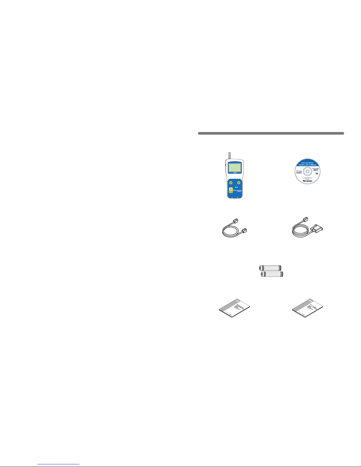
Contents of Package
The following items are included in the package.
Main Unit User’s Manual
and Warranty ×1
Software User’s Manual
and Warranty ×1
AAA Alkaline Batteries ×2
Communication Cable
(TR-3C10) ×1
Communication Cable
(RS-232C: D-sub 9 pin) ×1
Data Collector RTR-57C ×1
Collect List
Software
(T&D Recorder for Windows)
CD-ROM ×1
Page 8

5
◆ Part Names
Collect List
①
⑧
① Operation Dial
② LCD Display
③ Operation Buttons
④ Optical Communication Port
⑤ Communication cable connection jack
⑥ AC adaptor connection jack
⑦ Antenna
⑧ Battery Compartment
◆ Explanation of the Button Functions
List
・The downloaded data list will be displayed.
・Allows you to swift-scroll across data when viewing a graph or an event list.
・Al lows you to swiftly ma ke c hanges to the upp er and lower l imi t va lue
settings.
・Switch Power ON/OFF.
・
When downloading via wireless communication the [Select Group] display
will appear.
・Allows you to swift-scroll across data when viewing a graph or an event list.
・Allows you to swiftly make changes to the upper and lower limit value
settings.
Collect
②
Part Names and Functions
⑦
③
⑤
⑥
④
6
◆ How to Use the Operation Dial
〔Moving the dial up and down〕
●
By moving the dial up or down the arrow will move to allow you to choose
the desired item. The selected part will be displayed in an easy-to-see
inversed shade.
●
When sett ing a numerical value, by moving the dial up the value will
become la rg er and by m oving the d ia l down th e value w il l become
smaller.
〔Pressing in on the dial〕
●
By p ressing in on the dial, you can make a desired menu selection or
complete and activate a setting.
●
Keeping the dial pressed in (1.5 seconds) will activate different functions
depending on the display being viewed.
・If you keep i t pre ssed in whil e viewing the g raph displ ay, you ca n
change the display channel.
・If you keep it pressed in while viewing a menu, a setting display, or the
event list display, you will be returned back to the main menu display.
Press in
Move the dial up
Move the dial down
MAIN MENU
GATHER DATA
SEARCH RMOTE
MONITOR MODE
GATHER DATA
DATA LIST
REC SETTINGS
Page 9

7
◆ LCD Display
●
Af ter making a settin g, a djust the dial to
select [OK] and press to complete the setting
procedure.
●
A▲ indicates that there are more menu items
above ( ▲ ) or below the (▼) to view.
●
It em s marke d wi th( )i nd ic ate m en us for
Wireless Communication.
●
The item marked with an arrow( )denotes it
has been selected. If you move the operation
di a l u p an d do w n, the arr o w w i ll m ove
accordingly and by pressing in the dial the
item selected will be activated.
8
●
If there is no [OK] in the setting display, but
a [BACK ] is displayed, a djust the arrow t o
[BACK] and press it to complete the setting
and take you back to the menu display.
●
When carrying out a Remote Unit search, a
mark will appear next to Group Names in
wh i ch Re m ote Un its th a t c an car ry out
wireless communication are re gistered, as
well as, next to any Remote Unit name that
can carry out wireless communication.
●
Graph Display
Temperature, Humid ity, Voltage and Pulse
Da t a th a t ha s bee n dow n load e d t o an
RTR -57C un it can be disp layed in G raph
form. See p.37 for details about the display.
●
Event List Display
Event Data that has been r ecorded by
RVR-52 and downloaded to RTR-57C can
be viewed in a List Display. See p.39 for
details about the display.
〔Recorded Data Displays〕
OK
CH1
Page 10

9
Installing the Batteries
【Battery Life】
When battery life goes low, a battery life warning mark ( ) will be displayed
to inform you it is time to replace the battery.
Wh e n ba t tery l ife goe s lo w er, i n ord e r t o sav e d a ta, t he m ain u nit
automatical ly goes into sleep mode a nd cannot be turned on or operated
as usual. If all battery power disappears, all data will be lost so change the
battery as soon as possible. Also be aware that, if the batter y is left out of the
main unit for more than 2 minutes, all data will be lost.
◆ Install 2 AAA alkaline batteries.
●
AAA Ni-Cd and AAA Ni-MH(1.2V) batteries sold on the market can also
be used.
Battery Life Warning
Mark
NOTE:
●
Install 2 of the same kind of batteries.
●
Install the batteries in the correct direction to align + and -.
●
Battery charging via the main unit is impossible.
●
If you use an outside power source, batteries are not necessary.
●
The RTR-57C unit has no battery recharging ability.
10
●
To switch the power OFF, press the [POWER] button. You cannot switch
the power OFF with the Operation Dial.
●
Dur in g com munic ation , even by pressing the [ POWER] button, it is
impossible to switch the power OFF.
◆ Switch the power ON by pressing the POWER button
or the Operation Dial.
Switching the Power on
《Press the POWER button》
《Press the Operation Dial》
NOTE:
If using the monitoring function, the Auto Power Off function will not go into
effect.
【Auto Power Off Function】
If the main unit is not in us e for 3 minutes, the power will be automatically
switched off in order to save battery power. If you wish to continue to use,
switch the power on again.
Page 11
11
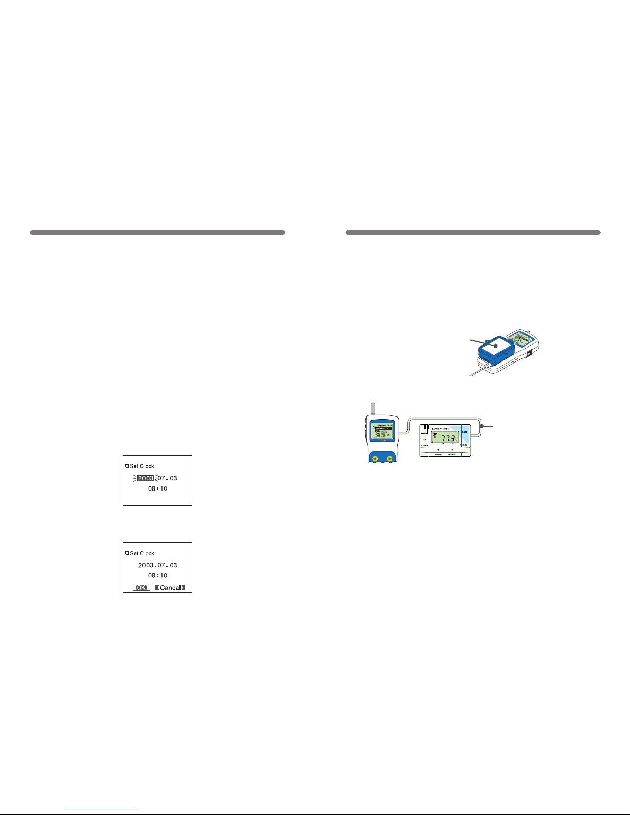
1.In the main menu open [SET FUNCTIONS] and then [Set Clock].
2.Setting the desired values.
① By moving the operation dial up and down, the selection item of the
display changes in the order of year, month, day, hour, and minute. By
pressing the dial, the value for that item will ash.
② Set to the desired value by moving the operation dial up and down and
press t he dial to set th at value. Move to the next item and follow the
same procedure.
3.When settings are completed, adjust to [OK] and press the dial to
complete the setting procedure.
Setting the Date and Time
CAUTION !
●
After purchasing this product, please be sure to use the attached software
to set the clock and date.
●
The differ enc e between your local time and GMT wi ll aut oma tic all y b e
calculated and written, after which the correct time will be displayed.
●
If the date and time of the RTR-57C main unit are not accurate, the starting
time of a programmed start and the recorded time of downloaded data will
be different from the actual one, so please set the date and time accurately.
●
When changing the battery, the time of the main unit may become incorrect;
please check the time after every change.
12
Communicating with the Data Logger
There are two ways to communicate between the RTR-57C
and the Data Logger.
【Via Cable / Optical Communication】
Via Communication Cable connection for TR-7 Series and Optical
Communication for RTR-51/52/53, RVR-52 and TR-5 Series.
◆ The following operations can be done using
communication via cable or optical communication.
●
Download Recorded Data
You can download any data that has been recorded in a data logger.
●
Set the Recording Conditions
You can c ontrol and change all recording s ettings suc h as Record ing
Mod e , Re c o rdin g Inte r val , and R e cord i n g S tar t D a t e an d T ime
(Programmed Start).
●
Read Logger Settings
The RTR-57C can read and display all settings for the data logger that is
connected to it.
〔
For RTR-51/52/53,RVR-52 and TR-51A/52
〕
Place logger face
down on RTR-57C
〔
For TR-71S/72S
〕
Connect using the included
communication cable (TR-3C10)
Page 12

【Wireless Communication】
Co mm unica tion can o cc ur vi a spe cial short ra dio waves w ith
RTR-51/52/53 and RVR-52.
◆ The following operations can be done using wireless comm-
unication.
●
Download Recorded Data
You can download data to the RTR-57C that has been recorded in data loggers
(RTR-51/52/53 and RVR-52) from a distance, without having to collect the units.
●
Check Remote Unit Conditions
You can check the battery life, current measurements and recording settings for
any unit registered Remote Unit.
●
Change Recording Conditions
You can cont rol and change all recording se ttin gs s uch as Recording Mode,
Recording Interval, and Recording Start Date and Time (Programmed Start).
●
Transmission distance is 100 meters if direct and unobstructed.
13
NOTE:
Wireless communication can only occur with those RTR-51/52/53 and RVR-52
logger units that have been registered as Remote Units via the accompanying
software『T&D Recorder for Windows 』.
100 meters
Remote Unit Remote Unit
Group
14
●
Read Logger Settings
The RTR-57C can read and display all settings for any selected data logger
that has been registered.
●
Search for Remote Unit (s)
A mark appears next to the name of any Remote Unit with which wireless
communication is possible.
●
Monitor Current Readings
You can moni tor the curren t m easurements of a Remote Unit at a set
interval or in groups with the measurements displayed consecutively.
◆
One Remote Unit can be set up to communicate with any
number of RTR-57C Units.
By registering the same Remote Unit info into a number of RTR-57C Units
it is possible to c heck and c on trol se ttings, as w ell as downl oa d to any
RTR-57C Unit that carries that Remote Unit’s registration information.
NOTE:
If you try to carry out communication between one Remote Unit and several
RTR-57C Units at the same time, an error message will appear.
Group
You can transfer the registration contents from one RTR-57C to another via
the attached software. For details see the [Help Menu] in『T&D Recorder for
Windows』 or the User’s Manual that accompanies it.
Page 13
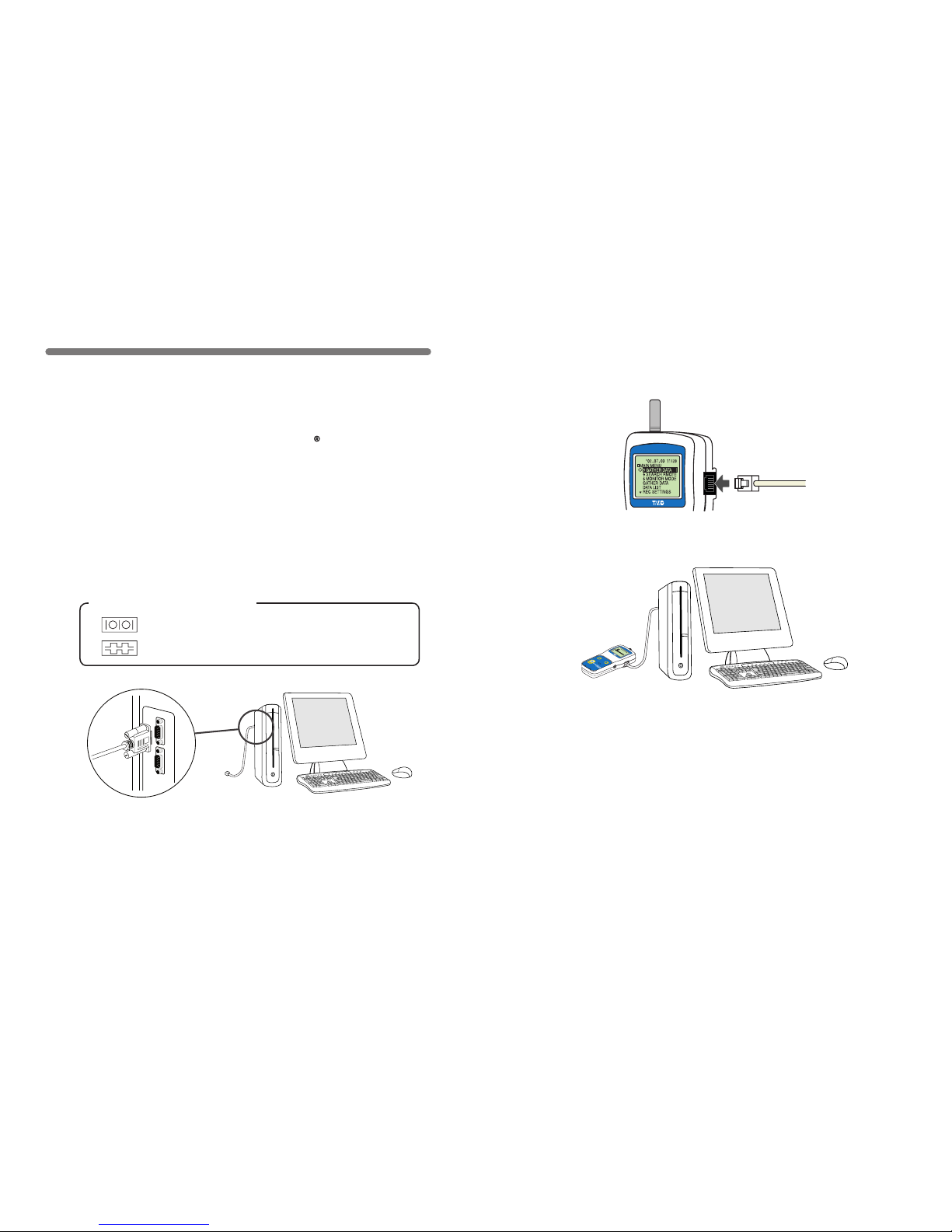
1.Connect the communication cable to your computer.
●
Connect the provided communication cable (RS-232C) to a serial port of
your computer.
Examples of Serial Port Symbols
The ca ble connection i s a D- su b 9p in m al e.
Please co nnect t o the place t hat has s uch a
symbol.
●
Be sure the connection is correct. If wrong, communication will not be
possible.
●
To prevent faulty contact, make sure to fully insert the communication
cable.
To download collected data to your computer, connect the RTR-57C
Unit to your computer with the communication cable provided.
NOTE:
Wireless communication cannot be done with the computer.
Communicating with the Computer
15
【Communication between RTR-57C and your Computer】
※ Downloading, editing and managing collected data can be done with the
provided software. For details about how to use the software, refer to the User’
s Manual that comes with『T&D Recorder for Windows 』or the [Help Menu] in
『T&D Recorder for Windows』.
16
2.Connect the communication cable to the RTR-57C.
●
To prevent faulty contact, make sure to fully insert the communication
cable.
メイン
メニュ
ー
WL
データ
スイア
ゲ
WL
コキ
ケンサ
ク
WL
オン
ド モ
ニター
データ
スイア
ゲ
データ
ソウサ
・リス
ト
キロク
カイシ
Collect
List
Page 14
2.In order to carry out wireless communication, register Groups and
Remote Units.
※ For details about how to register, see the [Help Menu] in the provided
sof tware『T&D Recor der fo r Wind ows 』or th e accomp anying U ser’s
Manual.
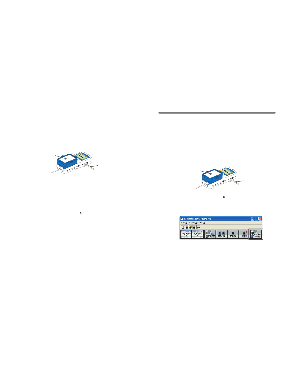
1.Connect the communication cable.
① Co nne ct th e RTR -5 7C Unit to yo ur co mpu te r w it h t he pr ovi de d
communication cable (RS-232C).
② Place the data logger on the RTR-57C.
メイン
メニュー
WL
データスイ
アゲ
WL
コキ ケン
サク
WL
モニタリ
ング
データ ス
イアゲ
データ ソ
ウサ・リス
ト
キロク カ
イシ
Communication Cable
(to computer)
Place the unit face down
on the RTR-57C.
NOTE:
If light enters during communication, an error will occur. Please make
sure to place the unit within the ridges for an exact t.
17
【Communication between RTR-51/52/53
RVR-52 and your Computer
】
18
Wireless Communication:
Remote Unit Registration
NOTE:
●
Wireless communication can only be carried out with RTR-51/52/53 and
RVR-52 units that have been registered as Remote Units via the provided
software『T&D Recorder for Windows』.
●
Please extend the antenna when using wireless communication.
1.Connect the cable so that communication can occur between the
data logger and your computer. (See p.15-17)
2.Open『T&D Recorder for Windows 』.
3.In the Main Window, click [Remote Unit Registration] and carry
out the registration.
◆ Register the data logger unit to be used as a Remote Unit.
If you wish to make Recording S tar t setting s via comp uter, se e the [Help
Menu] in the display for the type of logger you wi sh to make setting s fo r.
Details can also be found in the『T&D Recorder for Windows』User’s Manual
explanation of the [Recording Start] display.
メイン
メニュー
WL
データスイ
アゲ
WL
コキ ケン
サク
WL
モニタリ
ング
データ ス
イアゲ
データ ソ
ウサ・リス
ト
キロク カ
イシ
Communication Cable
(to computer)
Place the unit face down
on the RTR-57C.
[Remote Unit Registration]
Icon
Page 15
19
The following settings and changes can be made from the main unit:
●
Recording Start Date and Time (Programmed Start)
●
Recording Mode
●
Recording Interval
※
To change the unit of temperature (゜C or ゜F) in the RTR-51/52/53 units and the
measurement mode in the RVR-52 units, please use your computer and the
software『T&D Recorder for Windows 』.
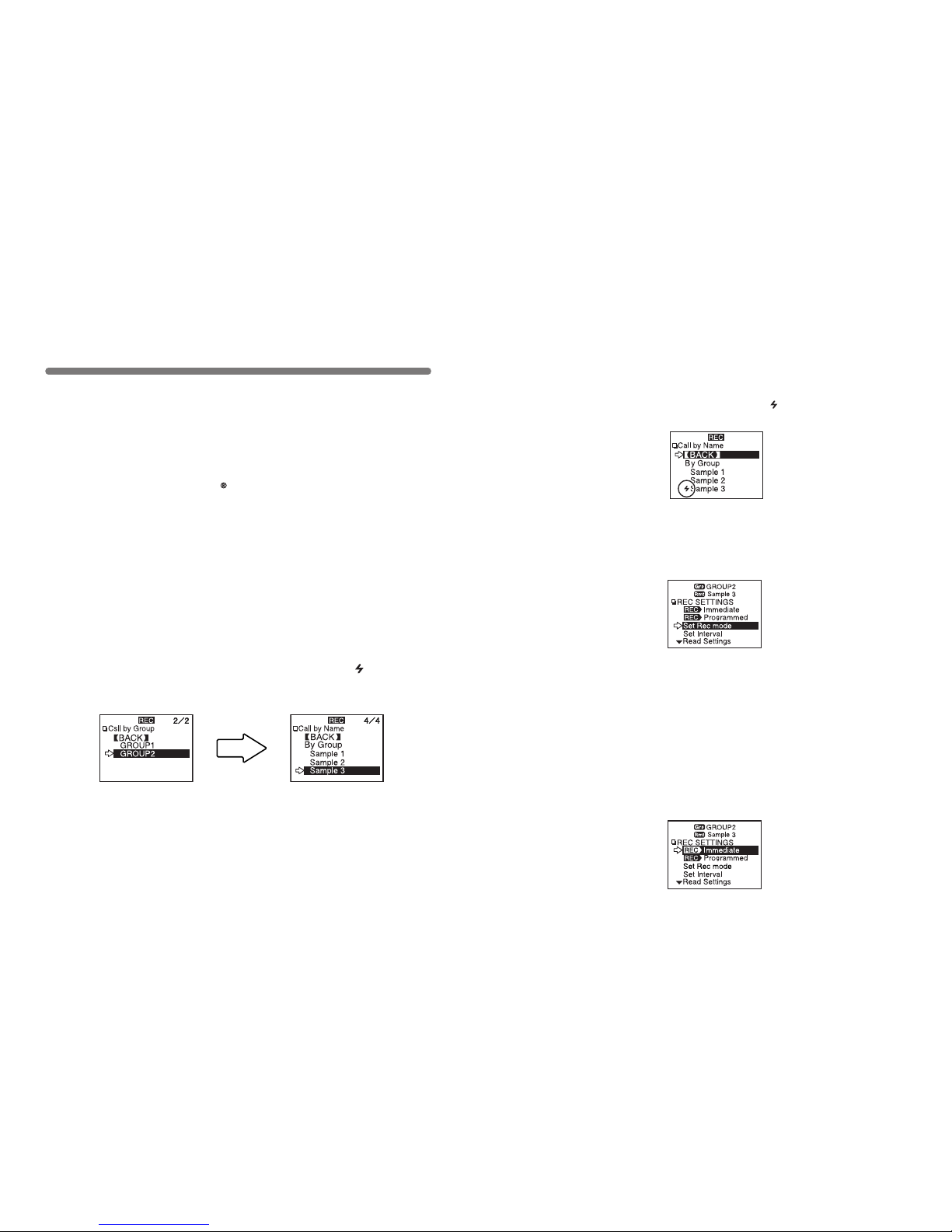
1.In the Main Menu, click [REC SETTINGS] and then [ Wireless].
2.Select the Remote Unit for which you wish to make settings.
【Immediate Start】
NOTE:
●
If you m ake recording c ondition changes w hile recording, al l previously
recorded data will be lost. Please make sure to download all recorded data
before making changes.
●
Changes in recording conditions will result in a lifting of the upper and lower
limits that had been set for each unit. If you wish for those settings to remain
in effect, p lease make sure t o use th e [ Read Set tin gs] func tio n befo re
making any changes. (See p.24 for details.)
Wireless Communication:
Recording Start
Wireless Communication:
Recording Start
① Select a Group in which
Remote Units are registered.
② Select a Remote Unit or a
Group.
20
●
Before selecting a Remote Unit you can run a search to nd all Remote
Units with which communication is possible. Those units with which
communication is possible will appear with a mark next to them.
(See p.45 for details)
●
Recording Modes:
One Time: Recording will stop when the data capacity becomes full.
Endless: Recording will continue with oldest data continuously
overwritten.
●
Recording Interval:
Choose from 15 intervals: 1,2,5,10,15,20,30 seconds and 1,2,5,10,15,20,
30 and 60 minutes.
3.Make Recording Condition Settings.
●
If you wish to make no changes and want to restart recording under the
same conditions, please read the current settings rst and then restart
recording. (See p.24 for details)
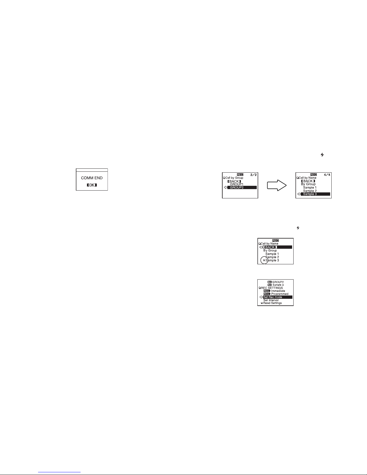
4.A fte r havin g com pl ete d the s ett in gs, a dj ust t he ar row ( >) to [ REC
Imm ediat e] an d pre ss di al to tran smit the r ecord ing c onditions to the
Remote Unit.
Page 16
21
5.Once transmission has been completed, a message will appear on the
display telling you communication was completed successfully. By pressing
the operation dial you can go back to the Recording Settings Menu Display.
The Remote Unit(s) will begin recording.
22
Recording Modes:
One Time: Recording will stop when the data capacity becomes full.
Endless: Recording will continue with oldest data continuously overwritten.
Recording Interval:
Choose from 15 intervals: 1,2,5,10,15,20,30 seconds and 1,2,5,10,15,20,30 and
60 minutes.
3.Make Recording Condition Settings.
●
Before selecting a Remote Unit you can run a search to nd all Remote
Uni ts wit h which communication is p oss ible. Those units wit h which
communication is possible will appear with a mark next to them.
(See p.45 for details)
1.In the Main Menu, click [REC SETTINGS] and then [ Wireless].
2.Select the Remote Unit for which you wish to make settings.
【Programmed Start】
① Select a Group in which
Remote Units are registered.
② Select a Remote Unit or a
Group.
Page 17
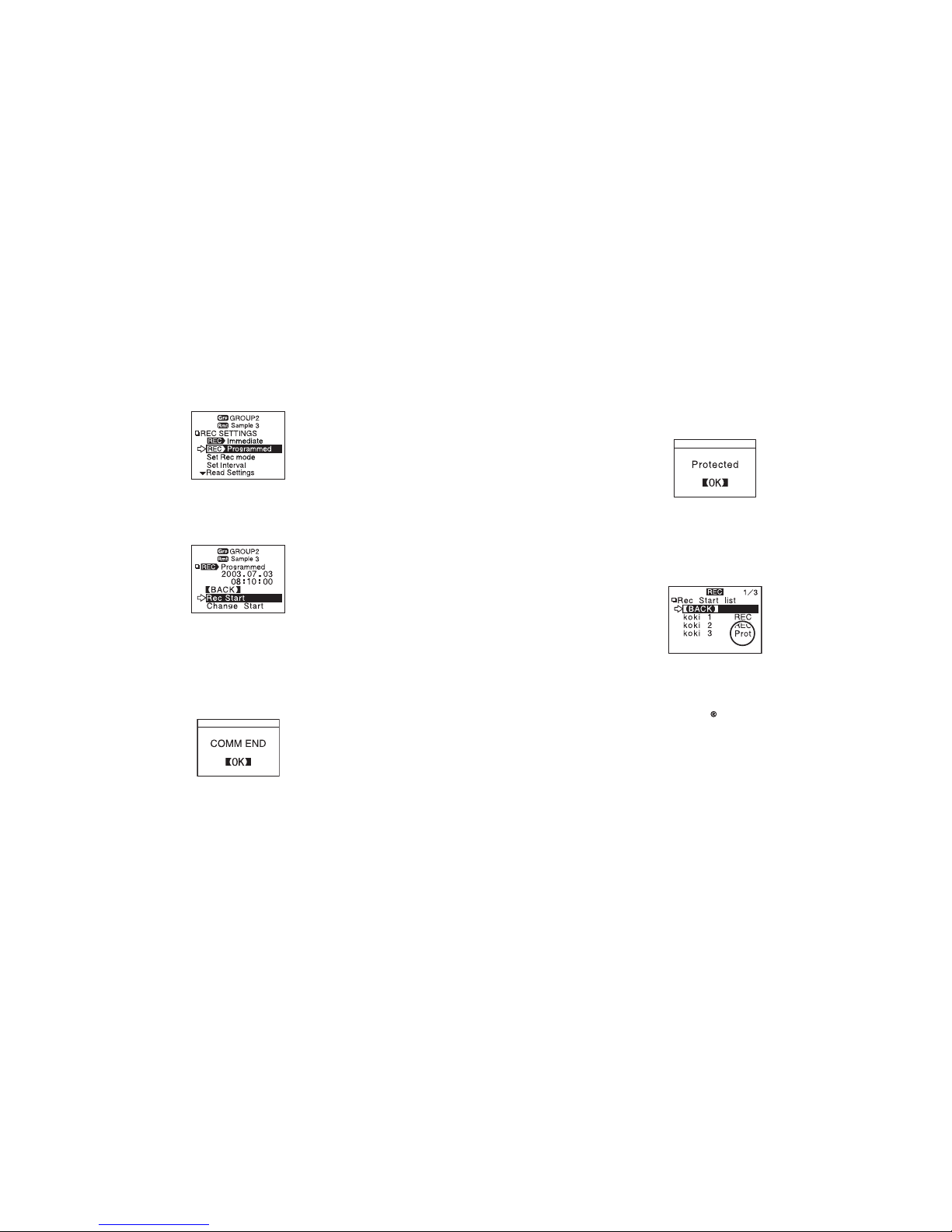
4.After having completed the settings, adjust the arrow (>) to [REC
Programmed] and press dial.
5.After having set the desired recording start date and time, adjust
the arrow (>) to [REC SETTINGS] and press the dial to transmit
the info.
23
6.Once transmission has been completed, a message will appear
on the disp l ay tell ing you comm unic a tio n wa s com plet e d
successfully. By pressing the operation dial you can go back to
the Recording Settings Menu Display.
The Remote Unit(s) will be put on Record Standby.
24
●
If a selected Remote Unit has been set to only start recording via computer
and has been to set to be protected against changes in the recording start
via wireless communication, the following message will appear.
【How to Lift the Protection】
For details about how to lift the protection see the Help Menu in the provided
software『T&D Recorder for Windows 』or see its User’s Manual.
◆ About Reading the Recording Settings
Select a Remote Unit and press on [Read Settings] in the REC SETTINGS
Menu. After reading, the recording settings information for the selected
Remote Unit will be displayed.
NOTE: If you select a Group, this reading of settings cannot be done.
◆ About the Default Settings
At any time, you can return the RTR-57C to its default settings of Recording
Mode: Endless and Recording Interval: 10 minutes.
●
When starting recording by Group, a list will appear showing the Remote
Units with which communication occurred.
[PROT] will appear next to those Remote Units which have been set to only
star t recording via computer and have been set to be protect ed a gainst
changes in recording conditions via wireless communication.
◆ About Forbidding Recording Start by Wireless
Page 18
About 2000 data readings can be downloaded per minute.
※ About 1000 event data readings can be downloaded per minute.
NOTE:
●
Wireless communication can only be done with RTR-51/52/53 and RVR-52
units that have been registered as Remote Units via the software『T&D
Recorder for Windows』.
●
Please extend the antenna before carrying out wireless communication.
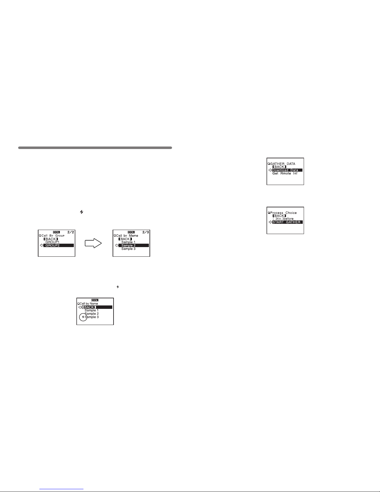
1.In the Main Menu, open [ GATHER DATA].
2.Select a Remote Unit.
●
Before selecting a Remote Unit you can run a search to nd all Remote
Uni ts with which com mun ica tion is pos sible. Those un its with wh ich
communication is possible will appear with a mark next to them.
(See p.45 for details)
25
Wireless Communication:
Downloading Recorded Data
① Select a Group in which
Remote Units are registered.
② Select the Remote Unit you
wish to download the data from.
26
3.Click [Download Data].
4.Set the period of data you wish to download and click [START
GATHER] to start downloading.
【Period of Data】
You can set the period (how many hours or days before now) from which
you wish to download data.
●
You can select from 1 ~ 47 hours (in 1 hour units) / 2 ~ 300 days (Less
than 100 days in units of 1 day, More than 100 days in units of 5 days)/
or ALL DATA.
●
If you specify the period of data that is earlier than the period of the data
saved in the remote unit, all saved data will be downloaded.
Page 19
27
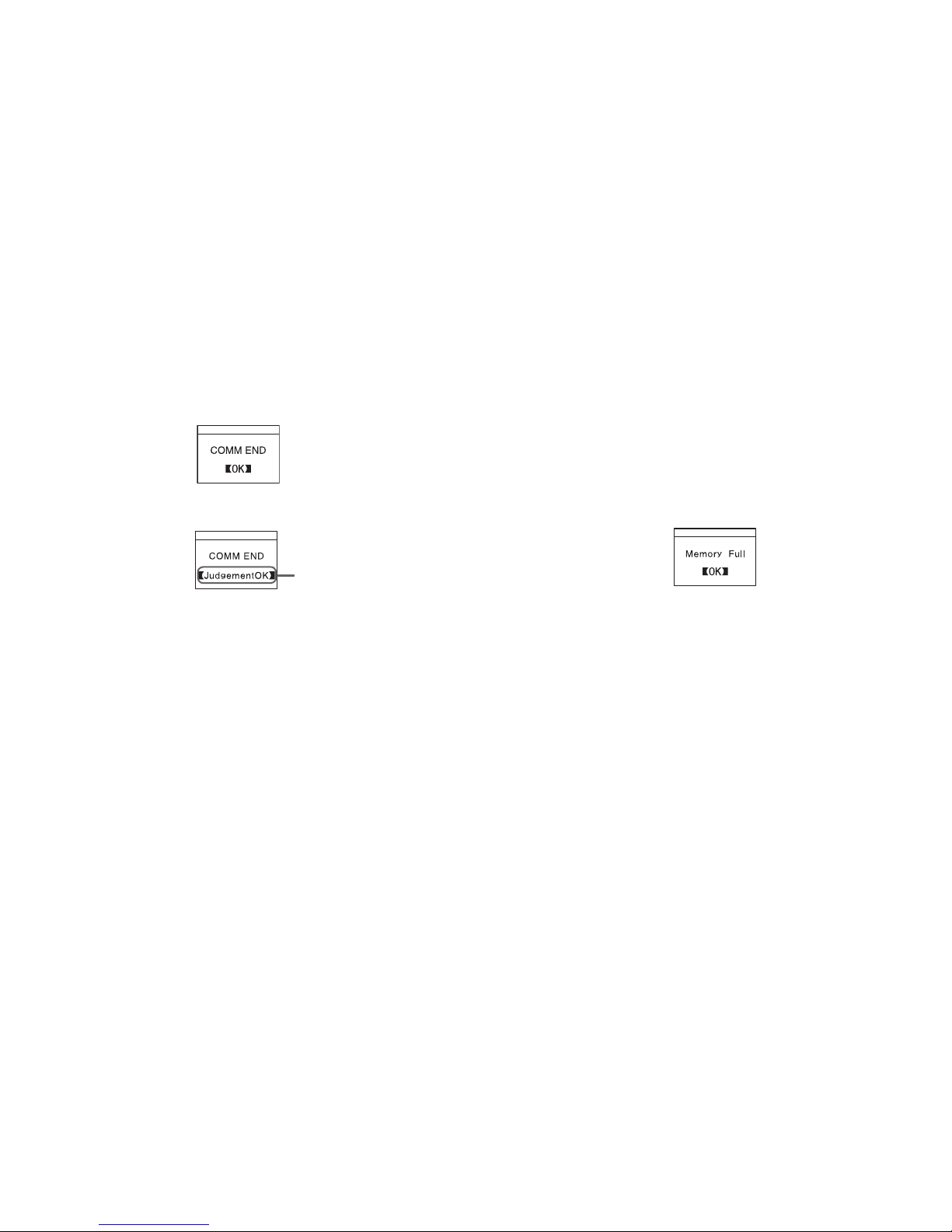
●
If you have set the judgment [ON] in [Set↑↓ Limits] before downloading,
the result will be displayed when the downloading is completed.
5.Whe n the d own l o adin g is c o mple t e d, a messa g e wi l l be
displayed.
By pressing the operation dial, the display will change to that of a graph.
Result
28
◆ If the amount of main unit memory is low, the downloading of
recorded data may be impossible.
When you check the amount of the memory to conrm whether the data you
wish to d ownload can be saved in the RTR- 57C, and the data cannot be
saved, the message [Memory Full] will be displayed and the downloading will
be canceled.
Carr y out any new download only after having downloaded and saved the
recorded data you wish to save into your computer and having deleted the
data from the RTR-57C main unit to make space.
See Page 51-52 for details about deleting data.
● The memory capacity is about 16 units of RTR-51 at full data (16,000
readings) capacity or about 256,000 readings.The maximum number of
times you can download recorded data before clearing the memory is
250; this holds true even if there remains empty memory.
● See Page 54 for details about checking the memory.
Page 20
29
The following settings or changes can be made via the main unit.
●
Recording Start Time Setting (Programmed Start)
●
Recording Mode
●
Recording Interval
※ Please make temperature unit changes for the RTR-51/52/53 main units
and Measurement Mode changes for the RVR-52 units via the supplied
software『T&D Recorder for Windows 』
NOTE:
●
If you set the conditions during recording, all previously recorded data will
be l os t. Ma ke sure to m ake all Record in g St ar t set ti ng s af te r ha vi ng
download the recorded data.
●
If you make chang es to the rec ording c ondit ion via the RT R-57C unit,
channel names may change. When you do not wish to change the names,
make sure to Read Settings before making changes.
※ RTR -51 /52 /53 and RVR-52 are not channel names, but are gr oup or
remote unit names, so these names will not change.
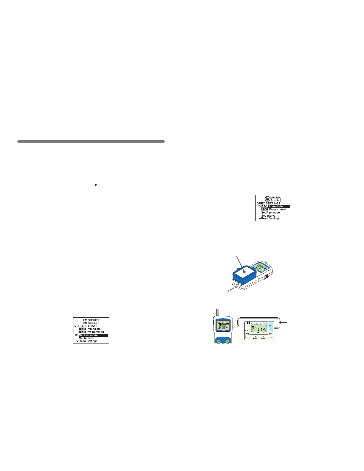
1.In the Main Menu. open [REC SETTINGS] - [Direct].
2.Set the recording conditions.
【Immediate Start】
【What does [Read Settings] mean?】
The recording conditions of a s pecied Remote Unit can be r ead in to an
RTR-57C unit.
If you wish to restart recording without making any changes to the recording
conditions, specify the Remote Unit and click [Read Settings]. The recording
conditions of the specied Remote Unit will be displayed.
Cable Communication:
Recording Start
30
4.Connect the data logger to the RTR-57C and press the operation
dial to have the settings transmitted.
3.Move the arrow to [Immediate] after setting the conditions.
Recording Modes:
One Time: Recording will stop when the data capacity becomes full.
Endless: Recording will continue with oldest data continuously overwritten.
Recording Interval:
Choose from 15 intervals: 1,2,5,10,15,20,30 seconds and 1,2,5,10,15,20,30 and
60 minutes.
※
Some recording intervals cannot be set on some types of the devices.
〔
For RTR-51/52/53,RVR-52 and TR-51A/52
〕
●
If light enters during communication,
an e rr or w il l oc cu r. Pl ea se m ake
su re to p la ce th e uni t wi thi n th e
ridges for an exact t.
Place logger face down on RTR-57C
〔
For TR-71S/72S
〕
Connect using the included
communication cable (TR-3C10)
Page 21
31
◆ About the Default Settings
At anytime, you can return the RTR-57C to its default settings.
Recording Mode: Endless
Recording Interval: 10 minutes
Channel Names: 1 channel…ch.1, 2 channel…ch.2
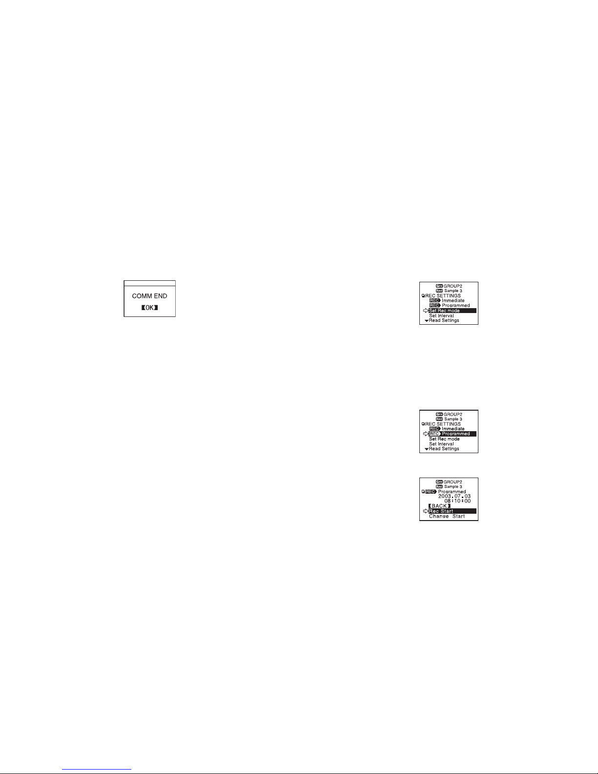
5.When communication has been completed the message [COMM
END] will be displayed and by pressing the operation dial, the
di spl ay wi ll return to th e m enu. The Re mot e U nit will st art
recording.
32
3.Move the arrow to [Programmed] after setting the conditions.
4.Set the recording start time and move the arrow to [REC START].
1.In the Main Menu, open [REC SETTINGS]-[Direct].
2.Set the recording conditions.
【Programmed Start】
Recording Modes:
One Time: Recording will stop when the data capacity becomes full.
Endless: Recording will continue with oldest data continuously overwritten.
Recording Interval:
Choose from 15 intervals: 1,2,5,10,15,20,30 seconds and 1,2,5,10,15,20,30 and
60 minutes.
Page 22
33
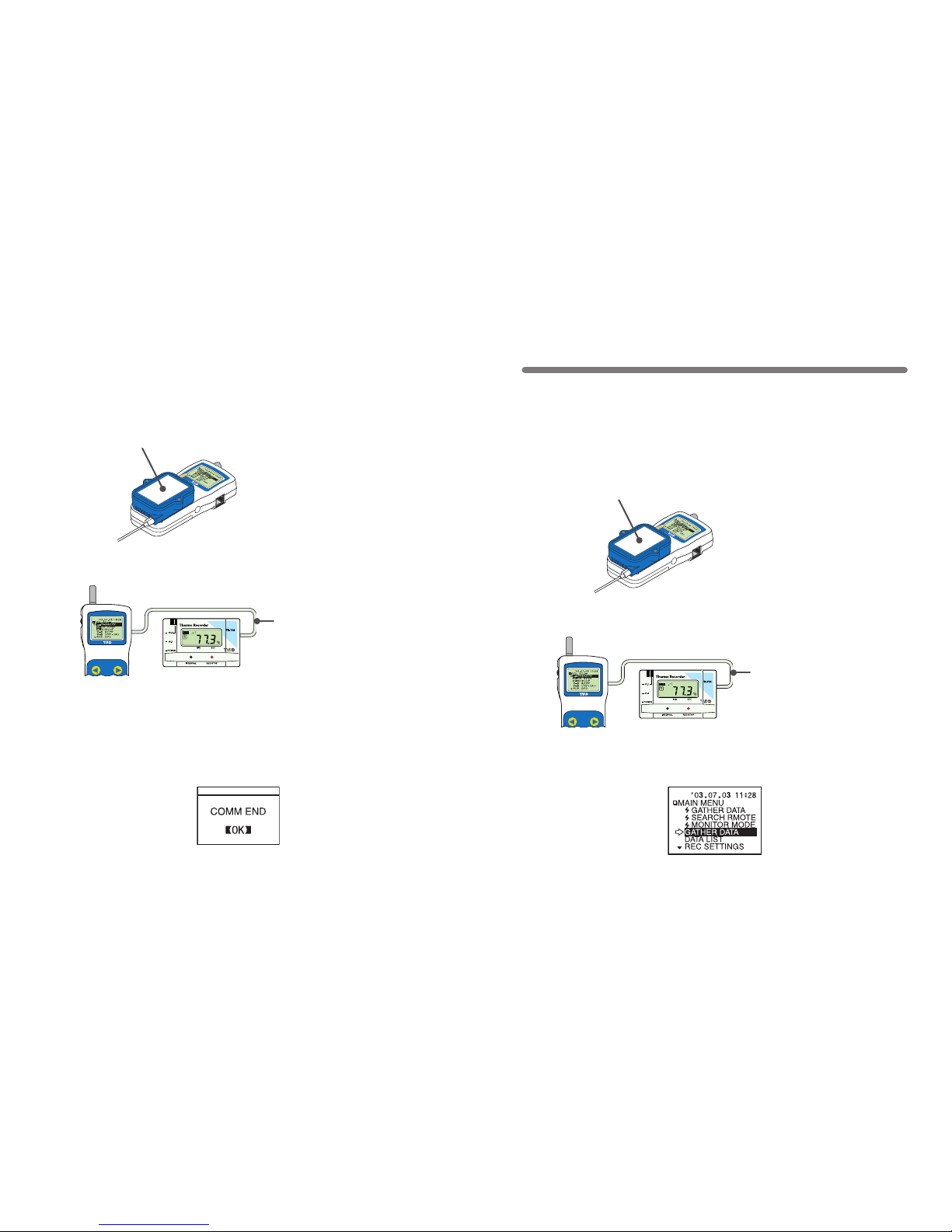
6.Once transmission has been completed, a message will appear
on the disp l ay tell ing you comm unic a tio n wa s com plet e d
successfully. By pressing the operation dial you can go back to
the Recording Settings Menu Display.
The Remote Unit(s) will be put on Record Standby.
5.Connect the data logger to the RTR-57C and press the operation
dial to have the settings transmitted.
〔
For RTR-51/52/53,RVR-52 and TR-51A/52
〕
●
If light enters during communication,
an e rr or w il l oc cu r. Pl ea se m ake
su re to p la ce th e uni t wi thi n th e
ridges for an exact t.
Place logger face down on RTR-57C
〔
For TR-71S/72S
〕
Connect using the included
communication cable (TR-3C10)
34
Download recorded data by connecting the data logger to
the RTR-57C.
1.Connect the data logger to the RTR-57C.
〔
For RTR-51/52/53,RVR-52 and TR-51A/52
〕
●
If light enters during communication,
an e rr or w il l oc cu r. Pl ea se m ake
su re to p la ce th e uni t wi thi n th e
ridges for an exact t.
Place logger face down on RTR-57C
〔
For TR-71S/72S
〕
Connect using the included
communication cable (TR-3C10)
Cable Communication:
Download Recorded Data
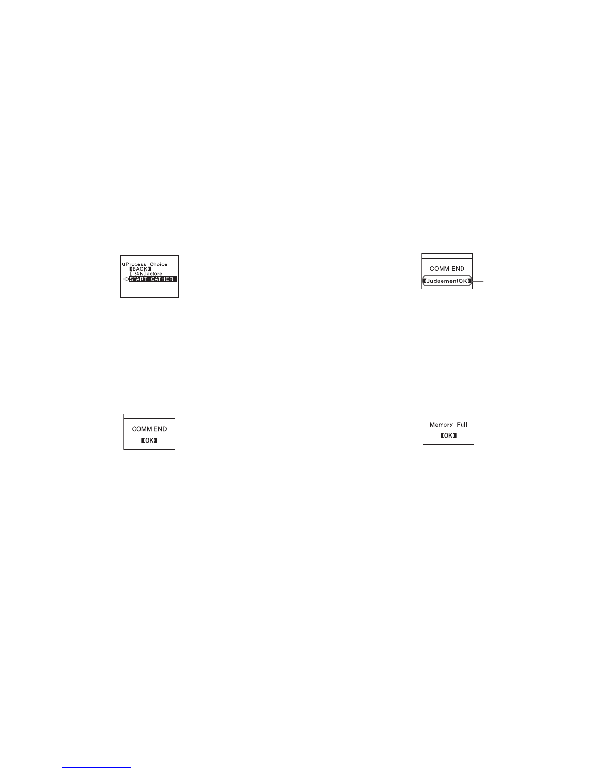
2.In the Main Menu, open [GATHER DATA] and downloading will
start.
Page 23
35
3.Whe n the d own l o adin g is c o mple t e d, a messa g e wi l l be
displayed.
By pressing the operation dial, the display will change to that of a
graph.
●
With RTR-51/52/53 and RVR-52 you can select to download data from
any number of hours or days before now.
・You can select from 1 ~ 47 hours (in 1 hour units) / 2 ~ 300 days
(Less than 100 days in units of 1 day, More than 100 days in units of 5
days) / or ALL DATA.
・If you specify a period of data that is earlier than the period of the
data saved in the RTR-51/52/53・RVR-52 Unit, all saved data will be
downloaded.
36
●
If you have set the judgment [ON] in [Set ↑↓ Limits] before downloading,
the result will be displayed when the downloading is completed.
Result
◆ If the amount of main unit memory is low, the downloading
of recorded data may be impossible.
When you check the amount of the memory to conrm whether the data you
wish to d ownload can be saved in the RTR- 57C, and the data cannot be
saved, the message [Memory Full] will be displayed and the downloading will
be canceled.
Carr y out any new download only after having downloaded and saved the
recorded data you wish to save into your computer and having deleted the
data from the RTR-57C main unit to make space.
See Page 51-52 for details about deleting data.
● The memory capacity is about 16 units of RTR-51 at full data (16,000
readings) capacity or about 256,000 readings.The maximum number of
times you can download recorded data before clearing the memory is
250; this holds true even if there remains empty memory.
● See Page 54 for details about checking the memory.
Page 24
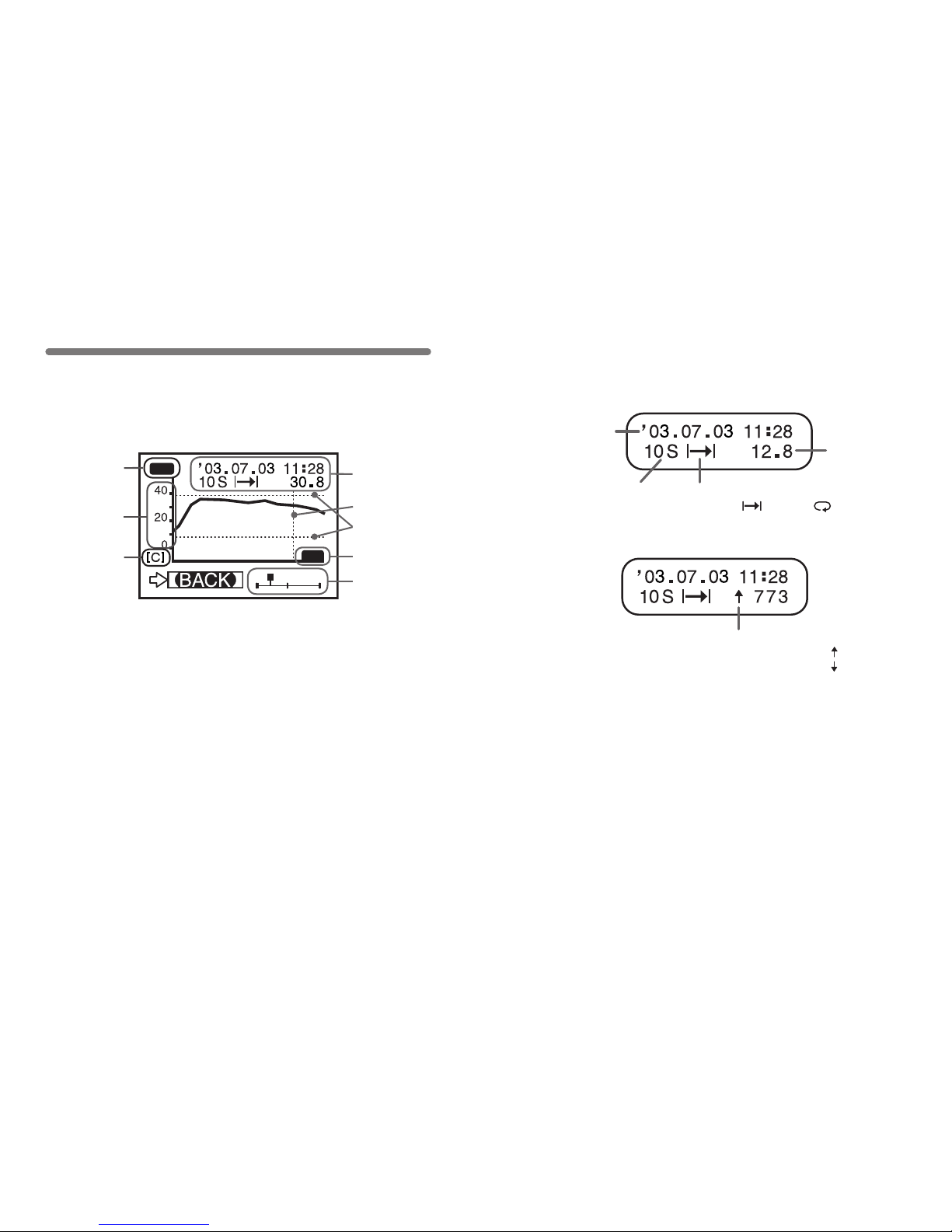
① Displayed Channel
If there is recorded data in two channels, by holding in the operation dial
for more than 1.5 seconds the channel will change.
② Scale
If you want to set the temperature display unit for Fahrenheit (゜F),
open [SET FUNCTIONS]-[Temp Unit C/F].
③ Vertical Axis Unit
[C] : Celsius, [F] : Fahrenheit, [%] : Humidity, [V] : Voltage, [P] : Pulse
37
In t his d ispl ay you c an v i ew i n gr a ph form t he d o wnlo a ded
temperature, humidity, voltage, and pulse data.
A graph is displayed for each channel of data and can be scrolled
left and right with the operation dial or by the buttons on the main
unit.
※⑥・⑦ are displayed when [Set ↑↓ Limits] has been set as ON.
Graph Display
OK
CH1
①
②
④
③
⑤
⑦
⑧
⑥
38
⑤ Cursor Bar (Fixed Display)
Cursor position is displayed and measurement information is displayed at
the top of the LCD display.
⑥ Upper and Lower Judge Range
When [ ↑↓ Judge] is ON, the range is displayed.
⑦ Upper and Lower Limit Judging Result
When [ ↑↓ Judge] is ON, the result is displayed.
⑧ Cursor
Shows which part of entire data is presently displayed in graph.
The display can be scrolled with the operation dial or the buttons on the
main unit.
Recording Date
and Time
Recording Interval
S:Seconds M: Minutes
Recording Mode
One Time: Endless:
Temperature Unit
④ Data Information
Displays the measurement information of the cursor bar position.
【For Pulse Data】
Response Polarity
Rising Edge (OFF → ON) :
Falling Edge (ON → OFF) :
Page 25
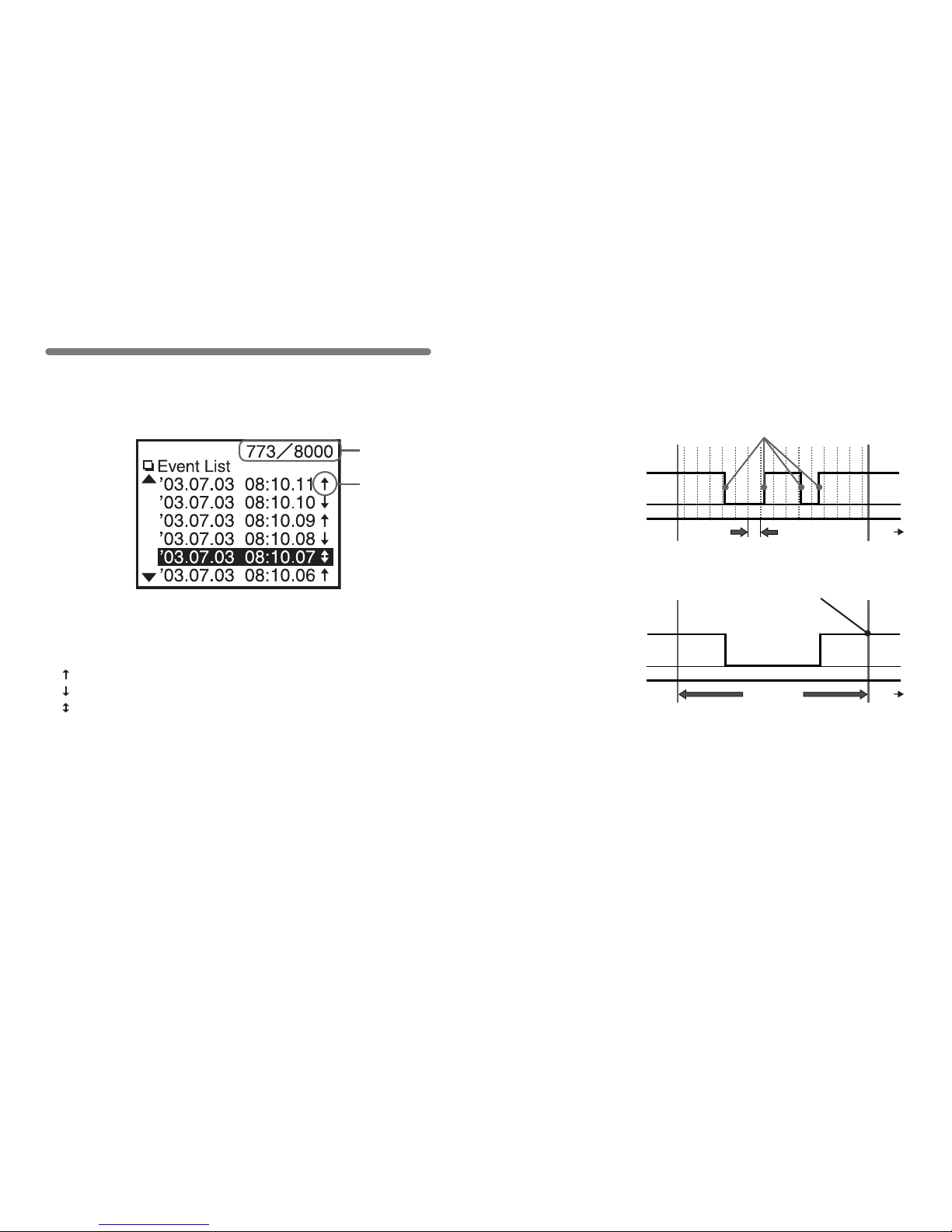
39
You can view the downloaded RVR-52 recorded event data on the
RTR-57C in an event data list. With the operation dial or main unit
buttons you can scroll up and down the data.
Event List Display
① Recorded Data Reading
Shows the reading number of the data at the cursor position.
② Arrows
: Rising Edge Data
: Falling Edge Data
: Both Rising and Falling within 1 second
①
②
40
◆ Measurements are taken every second and events are recorded
if any changes have occured.
High
Low
1 second
time
If both a rise and fall occur within 1 sec, the date
and time is recorded at this moment.
Mesurement
Signal
High
Low
time
1 second
The date and time are recorded at these
moments to signify an event.
Mesurement
Signal
Page 26
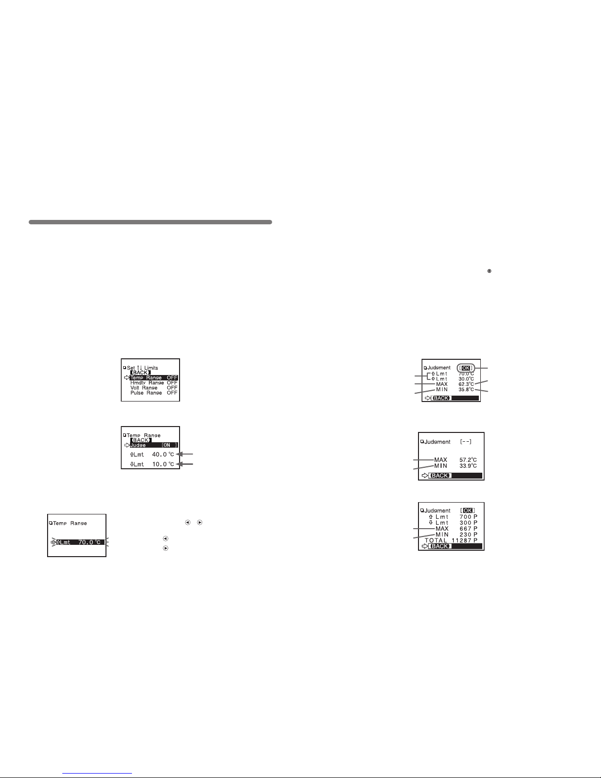
41
Checking Upper and Lower Limits
By sett ing u ppe r and lower limit s you can che ck data as i t i s
downloaded to see if all measurements fall within the limit range
and have the results displayed.
◆ Setting the Upper and Lower Limit Range
NOTE:
Upper and lower limit settings that were set by computer when setting up the
recording start time for the Remote Unit will take precedence over other limit
settings.
1.In the Main Menu, open [SET FUNCTIONS]-[ Set ↑↓ Limits] .
2.
Move the arrow to the item you wish to make settings for and open.
3.By clicking [Judgment OFF], it will change to [ON] .
4.By moving the arrow to the upper or lower limit and clicking, it will
allow you to make changes. By turning the operation dial, you can
make changes to the value; click to activate the new setting.
Upper Limit
Lower Limit
●
By holding down the ・buttons on the main
unit you can make rapid changes to the values.
Pressing the button will make the value lower.
Pressing the button will make the value higher.
42
◆ Viewing the Results of Saved Data
●
If no upper and lower limits have been set before downloading, the result
will appear as [--] and only the high and low values will appear.
●
If the data is pulse data, the total number of pulse readings will appear.
5.When settings are completed, click on [Back] to activate and
nish.
※ Settings can also be made via the computer. For details see the [Help]
Menu in the software『T&D Recorder for Windows 』or the User’s Manual
that accompanies it.
1.
In the Main Menu, open [DATA LIST] and select the data you wish
to check.
2.By clicking on [Judge], the results will be displayed.
Highest Temp
Lowest Temp
Result
Setting Range
HIGH
LOW
HIGH
LOW
HIGH
LOW
Page 27
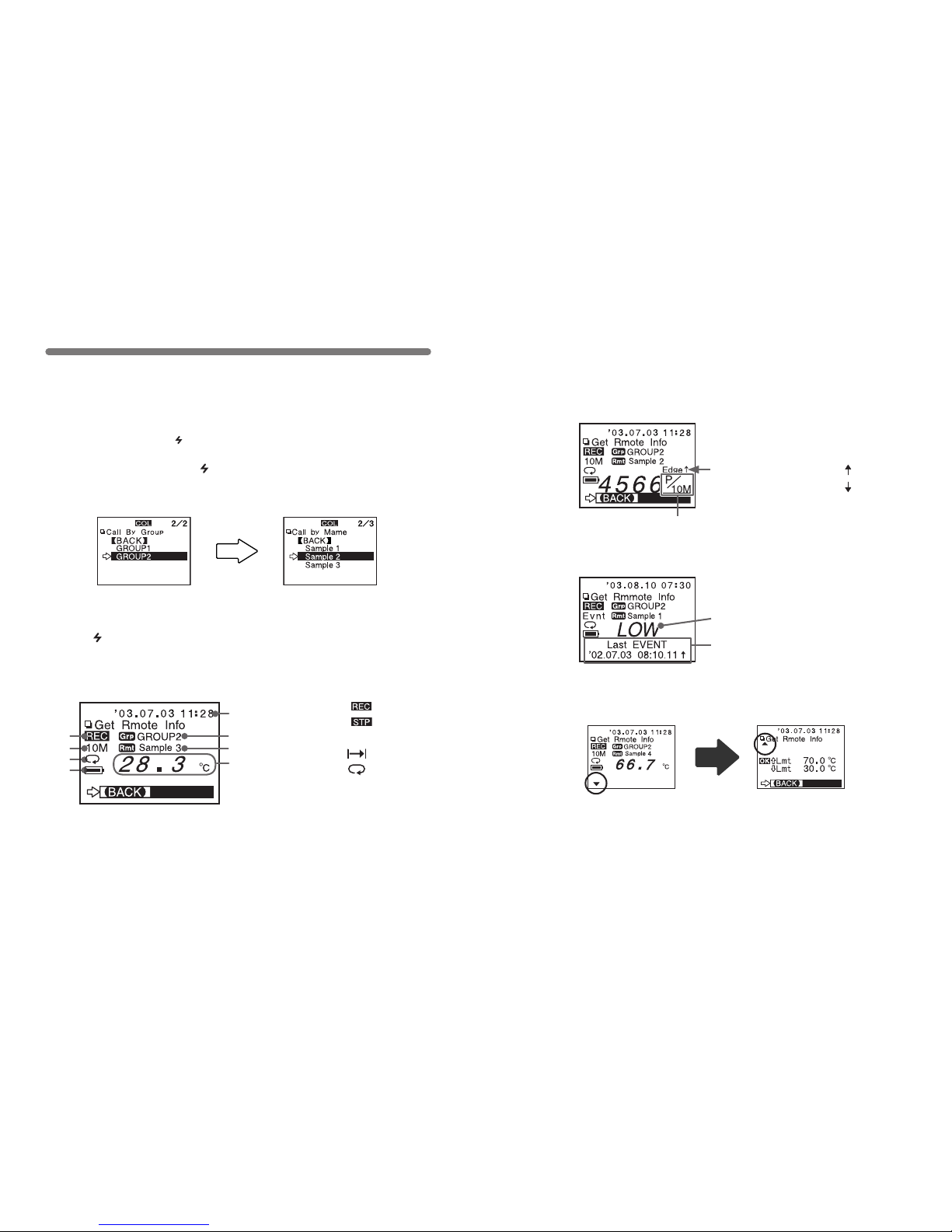
43
⑧
④
③
②
①
⑤
⑦
⑥
① Recording Status: …Recording
…Stopped
② Recording Interval:10 min
③ Recording Mode: …One Time
…Endless
④ Battery Life
⑤ Communication Date and Time
⑥ Group Name
⑦ Remote Unit Name
⑧ Measurement at Time of
Communication
Remote Unit Conditions Display
You can check selected Remote Unit info (Recording Conditions,
Current Measurements, and Battery Life, etc.)
② Select the unit you wish
to view.
① Select the group in which
the unit is registered.
※ Before selecting a Remote Unit you can run a search to nd all Remote Units
with which communication is possible.Those units with which communication is
possible will appear with a mark next to them. (See p.45 for details)
1.In the Main Menu, open [ Gather Data] .
2.Select the Remote Unit you wish to view.
3.Click [ Get Rmote Info] .
4.
Once communication has been completed, the Remote Unit info
will be displayed.
44
●
If upper and lower limit s have b een set a ▼ will appear in the lower left
corner of the display. By tur ning the operation dial you can view the limit
settings and the judgment results.
【For RVR-52 Pulse Recording】
【If RVR-52 has been set for Event Recording Mode】
If no event data has been recorded,
[No Event Data] will appear.
Recording Signal Condition
●
The total number of pulse readings during the recording interval set when
recording settings were made for the Remote Unit will be displayed.
・
Rising Edge (OFF → ON) :
・
Falling Edge (ON → OFF)
:
# of Pulses / Recording Interval
Page 28
45
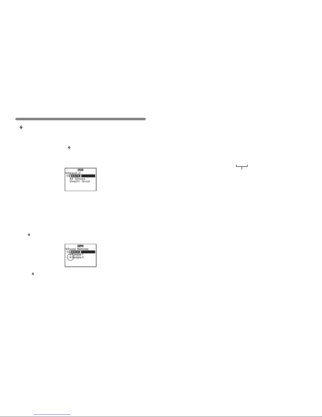
Searching for Remote Units
● The mark will continue to appear next to Remote Units with which
communication has become impossible until a new search is conducted.
● A search of 1 group will take about 20 seconds to complete. (The search
time depends on the number of Remote Units registered in the group.)
● By selecting a Remote Unit with which communication is possible and
clicking on it, you can either download data or get info about that unit.
●
By selec ting [Al l Groups ], th e search will be fo r Remote Units i n all
groups registered in the RTR-57C unit.
●
By selecting [Specify Group], the search will be for Remote Units in the
specied group.
A mark will appear next to all Remote Unit Names with which
communication is possible. This function can be useful when
selecting Remote Units for downloading data or starting recording.
1.In the Main Menu, open [ SEARCH RMOTE].
2.Select the search range from ([All Groups] or [Specify Group])
and click to start the search.
3.After the search has been completed, a list will appear showing
only the Remote Units with which communication is possible.
●
A mark will appear next to the Remote Unit names with which
communication is possible.
46
Dur ing step 2 at left, by h old ing in the operati on dia l, you can search for
Remote Units that have been additionally registered to the same group name
in another RTR-57C unit. Found Remote units will automatically appear with a
Remote name as shown below.
【Searching for Remote Units that have been additionally registered
in another RTR-57C Unit
】
S r 0 7 3
Remote Unit number at the time
of registration
Page 29
47
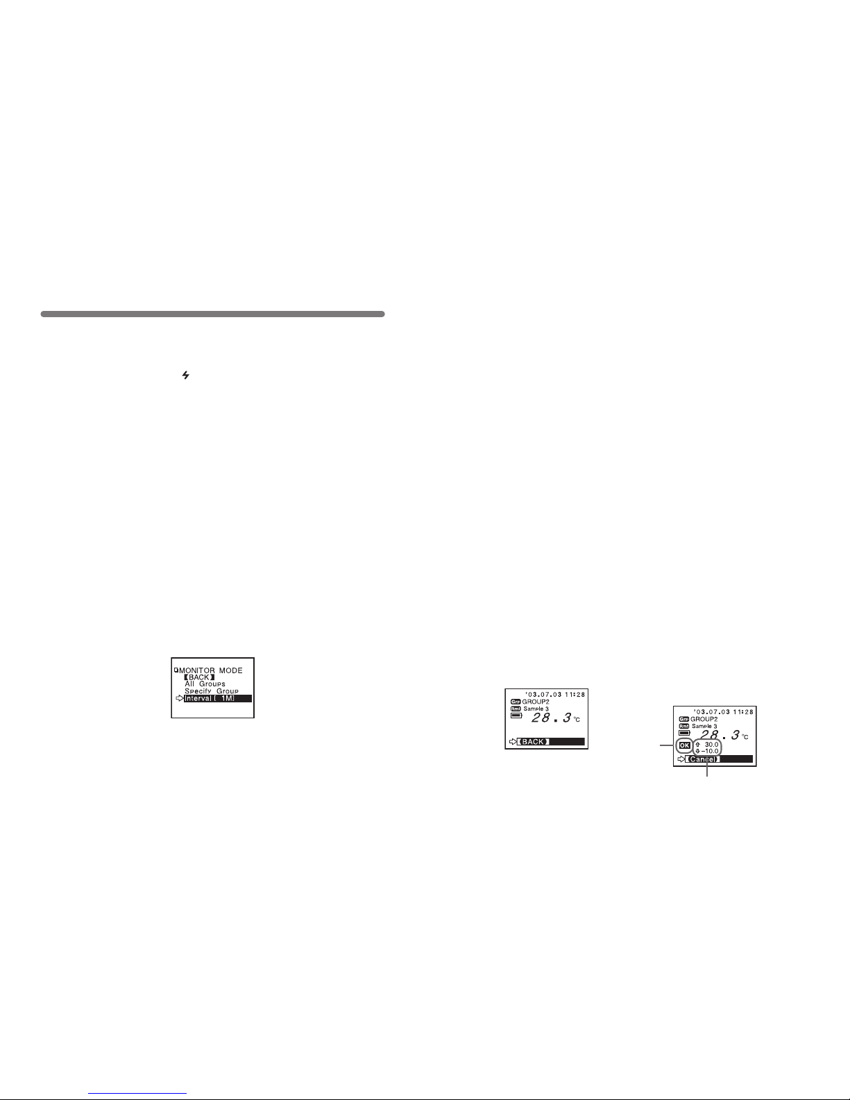
Monitoring
The RTR-57C can be set to patrol and monitor RTR-51/52/53 or
RVR-52 groups and display in order the current readings for view.
NOTE:
●
The amount of communication time depends on the number of registered
groups and remote units. Please note that if the monitoring interval is set
for less time than communication takes to complete a round of monitoring,
the system will automatically extend the interval to allow for the necessary
amount of communication time.
1.In the Main Menu, open [ MONITOR MODE].
2.Select the monitoring range.
[All Groups] :
Remote Units in all groups registered to the RTR-57C will be contacted
via wireless communication, and current measurement readings for those
units with which communication is possible will be displayed consecutively
ever y 2 seconds. Th is can be done for up to 120 units; the 121st unit’s
reading cannot be displayed.
[Specify Group] :
All Remote Units in th e selected group s w ill be contacted via wire les s
communication, and current measurement readings for those units will be
displayed consecutively every 2 seconds.
For those units with which communication is impossible the measurement
will be displayed as [----].
3.Select and set the Monitoring Interval
[Interval] :
The moni tor in g interval is the amo unt of t ime b etween the startin g of
wireless communication to gather current Remote Unit readings. Selections
can be made from 15 sec, 30 sec, and 1 to 60 minutes (in 1 minute units).
48
【If the upper and lower limit
settings are activated.】
NOTE:
●
The shorter the monitoring interval the sooner batteries will loose their
power.
●
<Communication Time for [All Groups] >
・If there are 64 Remote Units registered to the group
(24 seconds per group x Number of groups)
・If there are 250 Remote Units registered to the group
(54 seconds per group x Number of groups)
Moreover, the display time for each unit is about 2 seconds.
●
<Communication Time for [Specify Groups]>
The communication time will depend on the number of registered remote
units. For 250 units registered to 1 group the time will be 54 seconds plus a
display time for each unit of 2 seconds.
4.By selecting the monitoring range and clicking, the monitoring
search will begin.
● If u sing [Spe ci fy Grou p] , by sp ecifying th e gro up a nd clicking, t he
monitoring search will begin.
5.After the search has been completed, the current measurement
readings for those remotes reg istered in the group(s) will be
consecutively displayed.
● For RTR-53, the display will show in the order of temp / humidity.
● If the buzzer has been set to ON and a result is NG, a beeping sound will
go off.
Result
Upper and Lower Limits
Page 30
49
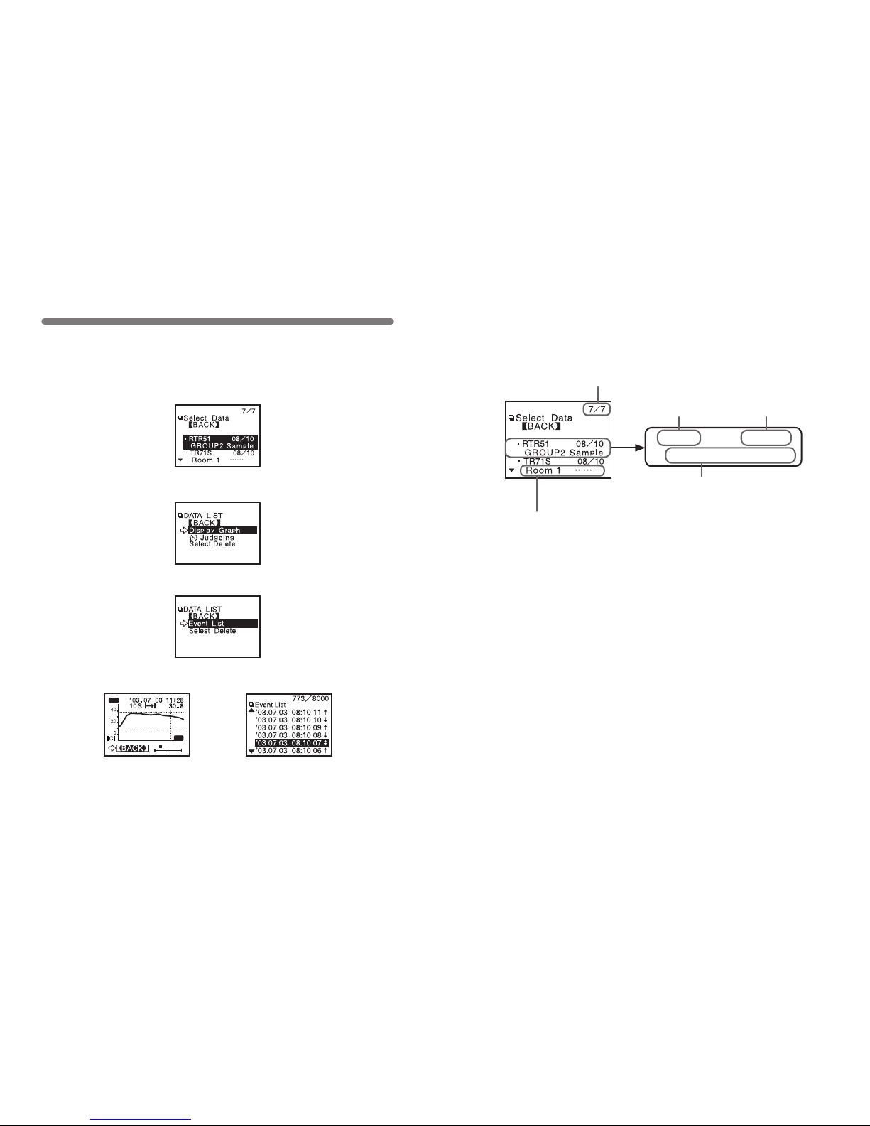
Displaying Recorded Data in Graph
OK
CH1
《Graph Display》
《Event List Display》
●
In the case of event list data, click [Event List]
1.In the Main Menu, open [DATA LIST] or press the [List] button on
the main unit to view the data list.
2.Select the data you wish to view from the data selection display.
3.Click [Display Graph]
3.The graph or event list will appear.
50
【Viewing a data list】
● Unregistered data loggers will appear by channel name.
● If a channel name shows [……].
This means that when the recording conditions were set via direct cable
connection between the data logger and the computer the channel name
was entered using two byte code
● Only the rst 6 letters of group and remote names will be displayed.
Group Name / Remote Unit Name
(If the data logger has been registered)
Downloaded dateDevice Name
Data Number (No. 7 of 7)
The most recently downloaded data will be on top.
・
RTR51
08/
10
G R O U P2 S a m p l e
Page 31
51
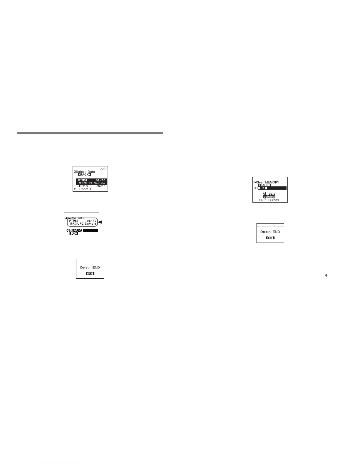
Deleting Data
◆ Deleting Selected Data
Info about data to be deleted
2.By clicking [Select Delete], a per mission message will appear
asking if it is [OK] to delete. If yes, move arrow to and click [OK] .
1.In the Main Menu, open [Data List] or press the [List] button on the
main unit. Select the data you wish to delete from the list and click.
3.When completed, a message will appear. Press the operation dial
to nish the deletion process.
52
◆ Deleting All Data
● Recording Conditions and other settings will not be deleted.
Recording conditions can be returned to the original factory settings by
going to [REC SETTINGS] – [Initialize] .
● Data deletion can also be carried out via the software and your computer.
For d etails, see the Help menu in『T&D Recorder for Windows』or t he
User’s Manual that accompanies it.
1.In the Main Menu, open [Set Functions] and [Clear MEMORY] .
2.A message asking for permission will appear, if OK, move arrow
to and click [OK] .
3.When completed, a message will appear. Press the operation dial
to nish the deletion process.
Page 32
53
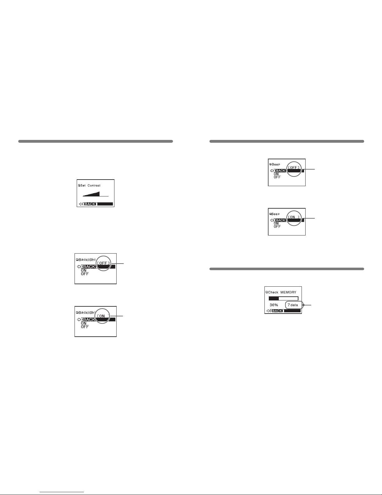
◆ Adjusting Contrast
◆ Using the Backlight
2.By moving the arrow to [ON] and pressing the dial, the setting will
be completed.
Adjusting the LCD
The present setting will be
displayed.
Upon completion the new
pr ese nt set tin g w ill be
displayed.
2.After completing the setting, press the dial to nish.
1.In the Main Menu, open [SET FUNCTIONS] and [Set Contrast]
● Move the operation dial up to make the display darker and down to make
it lighter.
1.In the Main Menu, open [SET FUNCTIONS] and [Backlight] .
3.Move the arrow to and click [BACK] to nish.
54
Muting the Operations Buzzer
Checking Memory
Number of Saved Readings
The pre se nt s ettin g wi ll
be displayed.
Upon completion the new
pr e se nt s et t in g w i ll be
displayed.
2.By moving the arrow to [OFF] and pressing the dial, the setting
will be completed.
1.In the Main Menu, open [SET FUNCTIONS] and [Beep] .
3.Move the arrow to and click [BACK] to nish.
2.By pressing the operation dial you can return to the SET
FUNCTIONS Display.
1.In the Main Menu, open [SET FUNCTIONS] and [Check MEMORY] .
Page 33
55
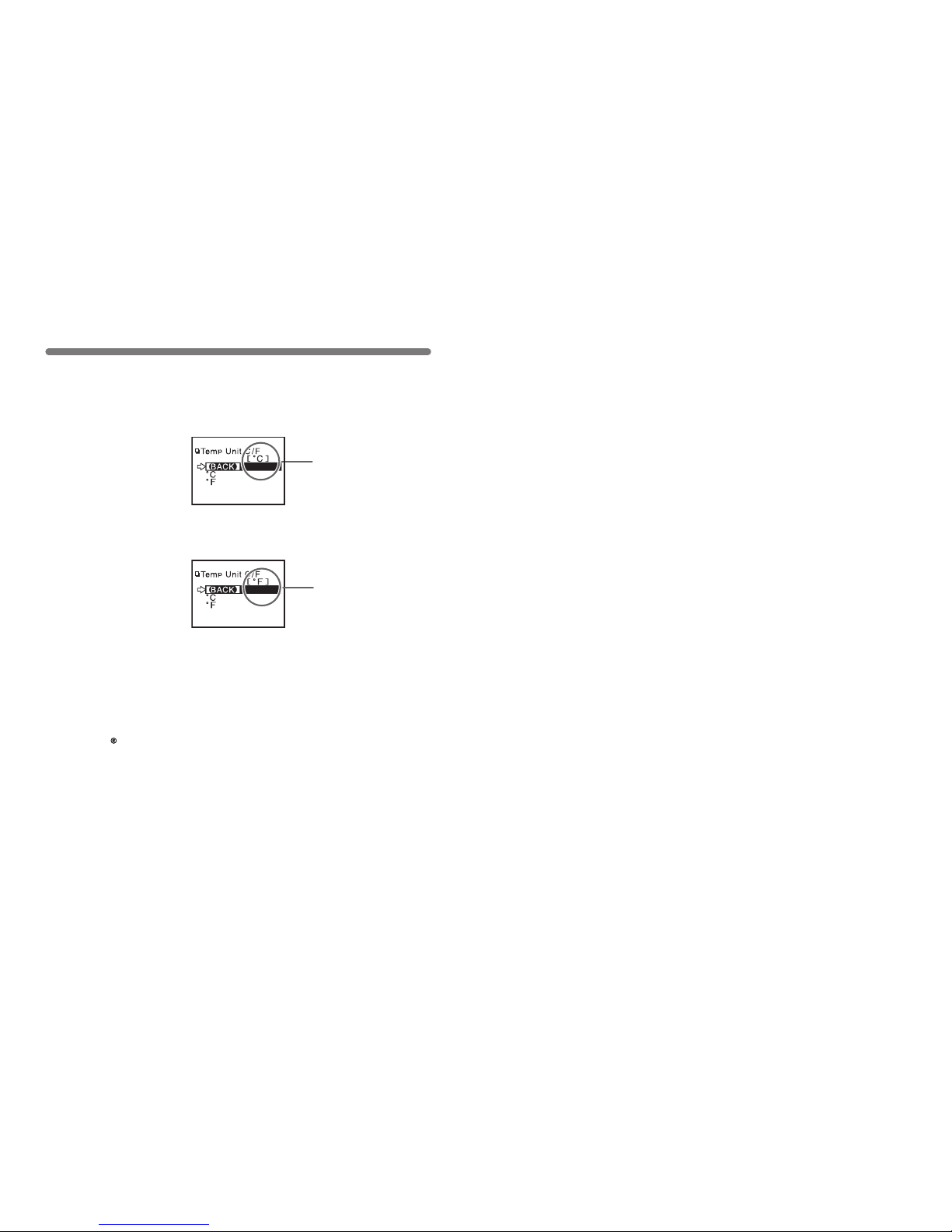
Changing Unit of Temperature
The present s ett ing will
be displayed.
Up on c ompl etio n t he
new present setting will
be displayed.
You can change the temp unit (℃ or ゜F) displayed on the RTR-57C
main unit.
◆ You can make or change Temperature Unit display settings for each
data logger in the Recording Start Settings display in the supplied
software. For details, see the Help menu in『T&D Recorder for
Windows』or the User’s Manual that accompanies it.
2.By moving the arrow to [ ゜F] and pressing the dial, the setting will
be completed.
1.In the Main Menu, open [SET FUNCTIONS] and [Temp Unit]
3.Move the arrow to and click [BACK] to nish.
56
Page 34
57
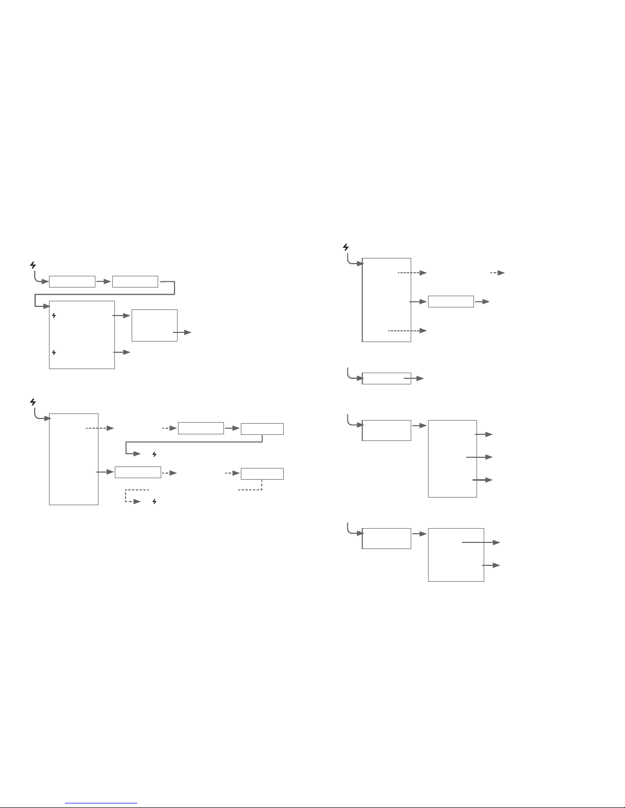
… Menus at a Glance …
Call by name
Call by name
SEARCH REMOTES
(See p.45)
【BACK】
All Groups
Specify Group
Start searching
groups
Call by Group
Start searching
for all remotes
Call by group
To [ GATHER DATA] MENU
To [ GATHER DATA] MENU
Search for selected remotes
For details about operations please see the relevant pages.
*1 You can select to download all data from any number of hours or days before now.
GATHER DATA
【BACK】
Download Data
(See p.25)
Get Remote Info
(See p.43)
After downloading, graph will
be displayed
Call by Group
Call by Name
View Remote Unit Info
【BACK】
[ALL DATA]*1
Start Gather
58
DATA LIST
Select Data
【BACK】
【BACK】
Display Graph
(See p.37)
↑↓ Judge
(See p.41)
Select Delete
(See p.51)
Displays the graph for that data
View results of judgement
After conrmation, select [OK] to
nish
MONITOR MODE…View Current Measurements (See p.47)
【BACK】
All Groups
Specify Group
Interval
Start search for
contactable remotes
Consecutive display of current
measurements of contacted
remotes.
Consecutive display of current data
of all remotes in group regardless
of contactability.
Call by Group
Select from 15 sec, 30 sec, and 1 to 60 minutes
(in 1 minute units)
GATHER DATA (See p.34)
Upon completetion, a graph will be displayed the current
data / time of downloading.
Start Gather
DATA LIST (For an Event List)
Select Data
【BACK】
【BACK】
Event List
(See p.39)
Select Delete
(See p.51)
Displays the event list data
After conrmation, select [OK]
to nish.
Page 35
59
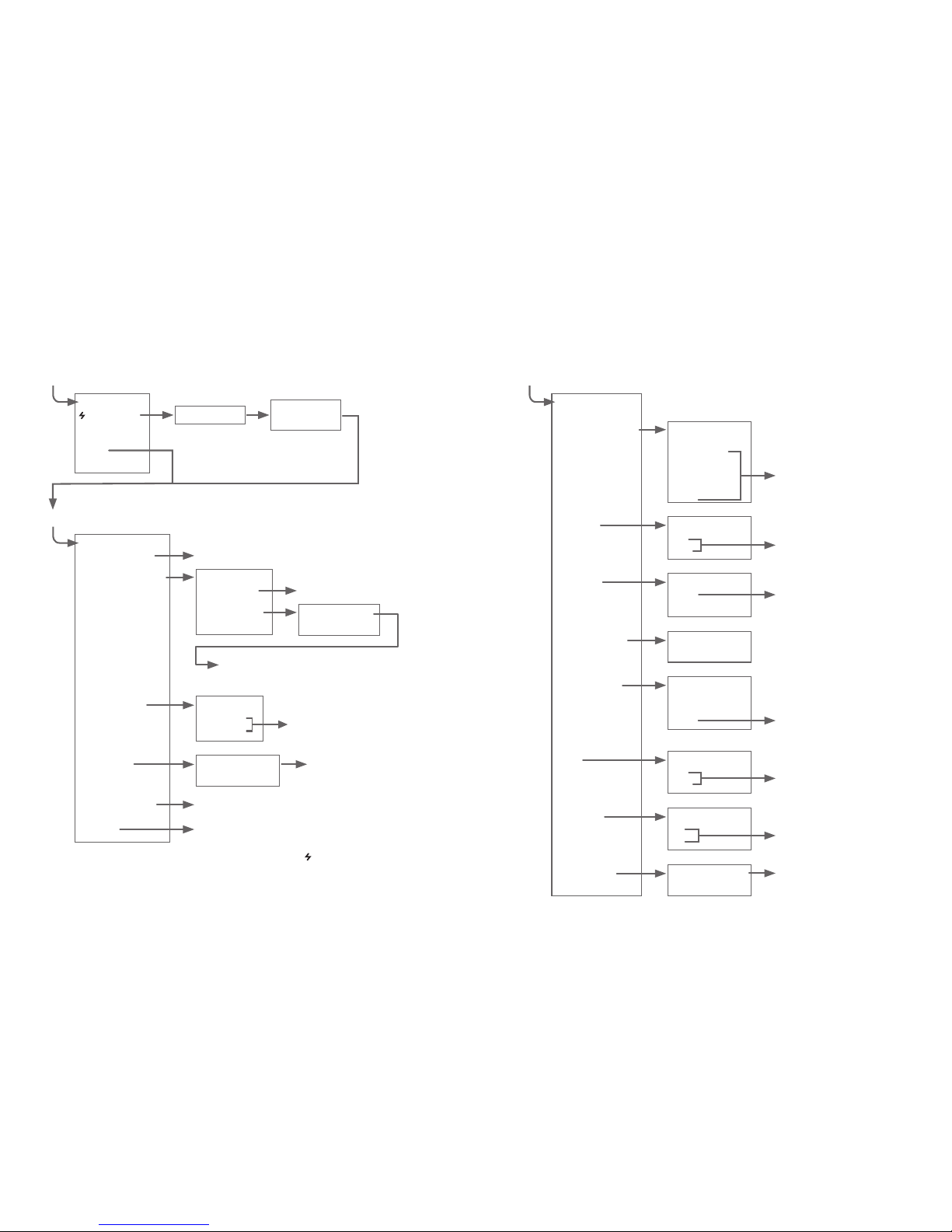
【BACK】
REC Immediate
REC Programmed
Set Rec mode
Set Interval
Read Settings*2
Initialize
REC SETTINGS
Setting Display
【BACK】
After c omple ti ng se ttings, click [ BACK] t o
nish.
【BACK】
REC START
Change Start
REC Start
Settings Display
【BACK】
Starts the reading of present settings.
【BACK】
One Time
Endless
After selecting, click [BACK] to
nish.
After setting, click [BACK]
to nish.
After conrming, click [OK] to nish
【BACK】
Wireless
(See p.19)
Direct
(See p.27)
REC SETTINGS
Package
Call by Name
*2 [Read Settings] is not displayed if you have selected [ Wireless] and [Package].
Record Standby
Call by Group
60
【BACK】
Upper and Lower
Limit Settings
(See p.41)
Backlight
(See p.53)
Set Clock
(See p.11)
Check Memory
(See p.54)
Clear Memory
(See p.52)
Beep
(See p.54)
Temp Unit
(See p.55)
Set Contrast
(See p.53)
Display
【BACK】
After selecting, click [BACK]
to nish.
【BACK】
ON
OFF
【BACK】
ON
OFF
【BACK】
℃
゜F
Settings Display
【BACK】
Temperature
Humidity
Voltage
Pulse
After setting, click [BACK] to
nish.
After selecting, click [BACK]
to nish.
After selecting, click [BACK]
to nish.
After conrming, click [OK]
to nish.
Conrmation
Display
【BACK】
【OK】
After setting, click [BACK] to
nish.
Settings Display
【OK】
【Cancel】
SET FUNCTIONS
Settings Display
【BACK】
After setting, click [BACK] to
nish
Page 36

61
Compatible Models
RTR-51
・
RTR-52・RTR-53・RVR-52
・
TR-51A・TR-52・TR-71S
・
TR-72S
Recording Capacity 16 units at full data 16,000 readings × 16 = 256,000 readings
Can hold up to 250 downloading sessions
Functions Downloading Data (possible to display results of upper and lower
limit check after downloading)・Display Saved Data Graphs
・
Display Highest and Lowest Temperature・Set Recording Start
for Remote Data Loggers・Delete Stored Data (one reading
・
all readings)・Monitor Current Temperature・Search for Remote
Units
LCD Display Operation Menu・Graph Display・Low Battery Life Warning・
Calendar and Clock・Contrast Adjustment・Backlight
Power TTwo AAA Alkaline Batteries (LR03)・Can use rechargeable AAA
Ni-Cd or Ni-MH 1.2V batteries・Special AC Adaptor (AD-0604)
Batter y Life 100 hrs under Continuous Operation
Auto Power Off Function (Turns unit off after 3 minutes of non-use)
Data Backup Approx. 1 year with switch off Data erased if all battery power is lost
Wireless Method ETSI EN300-220
Transmission Distance Up to 100 meters (May vary with conditions)
Interface
Communication Speed Special Short Wave Radio Type: approx. 2,000bps / min
(with data logger)
Modular Jack:
Serial Communication(RS-232C) 19,200bps (with computer)
9,600bps (with data logger)
Optical Communication: 2400bps (with data logger)
Interface
Communication Time Data from RTR-57C to Computer:
One Full Logger’s Data ~ 25 sec.
Data from RTR-51 / 52 / 53 / RVR-52 to RTR-57C via wireless:
One Full Data~420sec.
Data from TR-7 Series to RTR-57C via cable:
One Full Data ~ 50sec.
Data from TR-5 Series to RTR-57C via optical:
One Full Data ~ 160sec.
Dimensions H 125mm x W 58mm x D 25.5mm (excluding protruding part)
Antenna Length: 20mm-105mm (fully extended)
Weight Approx. 125g. (Including 2 AAA Alkaline batteries)
Operating Conditions Temperature: 0 to 50℃
Humidity: Less than 90% RH (Without dew condensation)
Specications for
RTR-57C Data Collector
62
Accessories Included Computer Communication Cable (RS-232C:D-Sub9 pin:1.5m) x 1
Data Logger Communication Cable (TR-3C10:1m) x 1
AAA Alkaline Batteries (LR03) x 2
User’s Manual and Warranty x 1
Software (T&D Recorder for Windows) x 1
Page 37
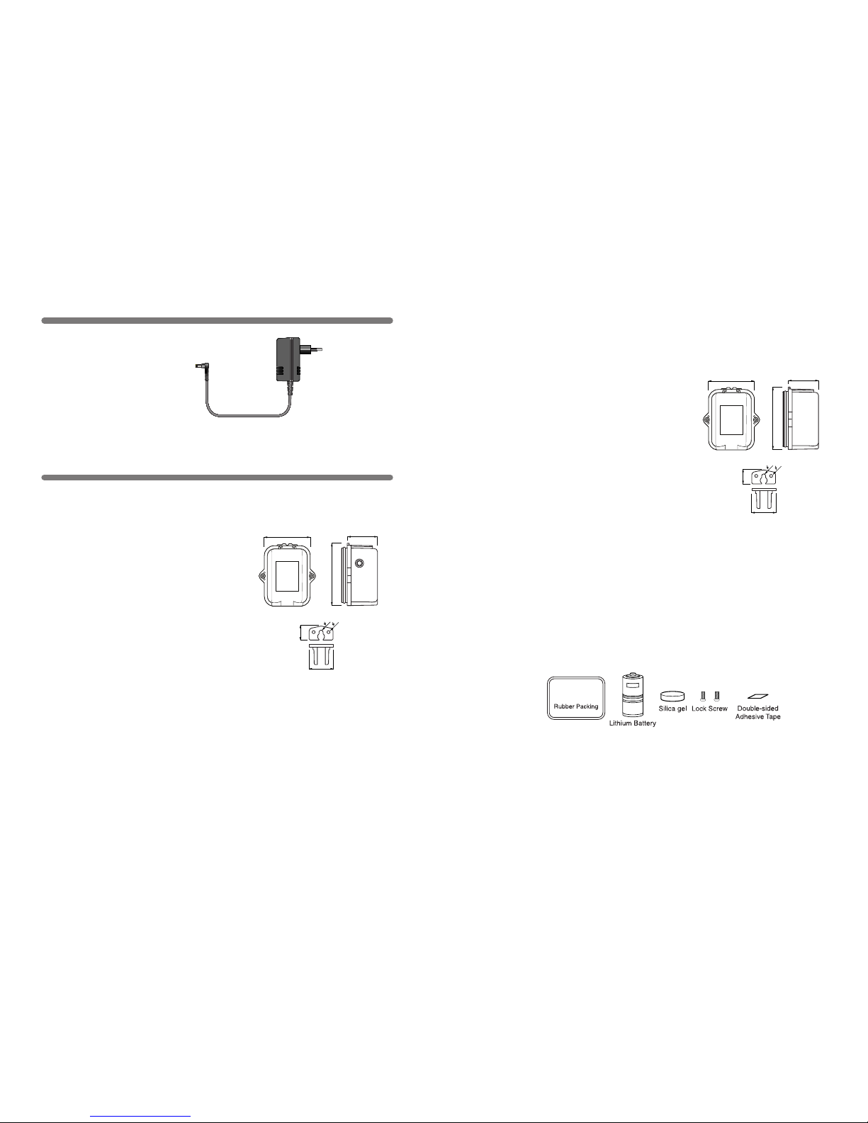
63
Options
◆
AC Adaptor
AD-0604
Cable length : 1.85m
Input: 230V/50Hz
Output: DC6V/50mA
47
62
31
24
14
3
4
For RTR-5/RVR-5
◆ External Power Adaptor
RTR-05A1
Voltage Input: DC6V (Nominal)
Back-up Power: Ni-MH Battery
(In case of power loss)
Back-up Time: 4 days (*1)
Charging Method: Trickle Charge
Operating
Temperature: 0 to 60℃
Waterproof
Capability: None
Weight: about 37g (without AC adaptor)
Kit Contents: AC Adaptor (AD-0604) x 1
Attachment hook x 1
Rubber Packing x 1 (for back of main unit)
Rubber Packing (small) x 1
(for AC adaptor jack)
Silica Gel Pack (drying agent) x 1
Double-sided Adhesive Tape x 1
(for fastening silica gel)
Screws x 2
(extras for fastening back of main unit)
64
62
31
47
24
14
3
4
NOTE:
(*1) Batter y Life varies depending on measuring environment, recording interval,
transmission frequency, and ambient temperature. The battery life estimated here
is calculated using a new battery under normal operating conditions and is no way
should be understood as a guarantee of battery life.
(*2) Operating temperature depends on the specications for the data logger being
used.
◆ Large Capacity Battery Pack
RTR-05B1
Power: Lithium Batter y x 1 (LS26500)
Battery Life: about 2 years and 6 months (*1)
(Monitoring at 1 minute interval
= about 20 months)
Waterproof
Capability: Splash proof
Operating
Temperature: -40 to 80℃ (*2)
Weight: about 75g (including lithium battery)
Kit Contents: Lithium Battery x 1 (LS26500)
Attachment hook x 1
Rubber Packing x 1 (for back of main unit)
Silica Gel Pack (drying agent) x 1
Double-sided Adhesive Tape x 1
(for fastening silica gel)
Screws x 2 (extras for fastening back of main unit)
◆ Battery Set for Large Capacity Battery Pack
RTR-05B2
Kit Contents: Lithium Battery x 1 (LS26500)
Rubber Packing x 1 (for back of main unit)
Silica Gel Pack (drying agent) x 1
Double-sided Adhesive Tape x 1 (for fastening silica gel)
Screws x 2 (extras for fastening back of main unit)
Page 38
65
◆
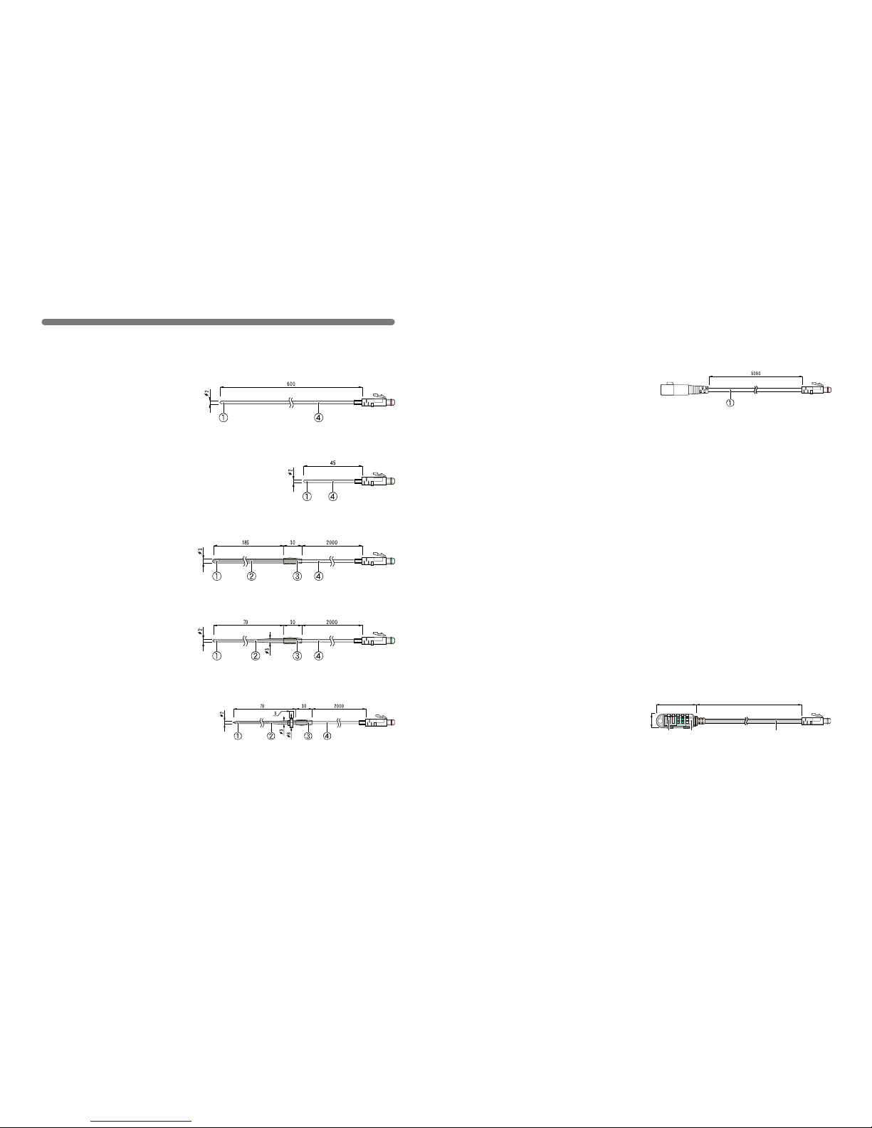
Temperatue Sensors
(For TR-52/RTR-52)
unit : millimeters
Optional Sensors
TR-5106 Teon-Shielded Sensor
Cable Length: 45mm
Thermal-Constant Time :
In the air : Approx. 15 Sec.
In agitated water : Approx 2 Sec
TR-5101 Teon-Shielded Sensor
Cable Length: 0.6m
Thermal-Constant Time :
In the air : Approx 15 Sec.
In agitated water: Approx 2 Sec.
TR-5220 Stainless Protection Sensor
Cable Length: 2.0m
Thermal-Constant Time :
In the air:Approx 36 Sec.
In agitated water: Approx 7 Sec.
TR-5320 Stainless Protection Sensor
Cable Length: 2.0m
Thermal-Constant Time :
In the air: Approx 12 Sec.
In agitated water: Approx 2 Sec.
TR-5420 Stainless Protection Sensor
Cable Length : 2.0m
Thermal-Constant Time:
In the air:Approx 12 Sec.
In agitated water: Approx 2 Sec.
Materials:①Thermistor ②Stainless pipe(SUS316) ③Teon Compaction Tube
④ Teon Resin (FEP)-Shielded
Possible Measurement Range: –60 to 155℃ Sensor Temperature Durability: –70 to 180℃
Water Resistance: Splash Proof (Sensor and Cable)
Measurement Accuracy: Average ±0.3℃ (-20 to 80℃ )・Average ±0.5℃ (-40 to -20℃ /80 to 110℃ )
・Average ±1.0℃ (-60 to -40℃ /110 to 155℃ )
66
◆ Sensor Extension Cable
(
Temp Sensor Only
)
unit : millimeters
TR-2C30
Cable length: 3.0m
Splash Resistant
Materials:①Vinyl Coated Electrical Wire
TR-3310 Temp / Humidity Sensors
Possible temperature
measurement range :
0 to 55
℃
Possible humidity
measurement range : 10 to 95% RH
Sensor temperatur
resistance : -10 to 60
℃
Temp measurement
accuracy : average±0.3
℃
humidity measurement
accuracy : ±5%RH
(
At 25℃ 50%RH
)
Service life : 1 year (under normal operational conditions)
Operational conditions : Without dew condensation, water leakage or effect from
corrosive gas or organic solvents.
Cable length : 1m
34
12
1000
①
②
③
NOTE:
Only one cable per sensor. When using the extension cable there will be a
+0.3℃at normal temperature and at -50℃a gap of +0.5℃may occur.
Materials:①Temperture/humidity sensor
②
Polypropylene resin
③
Vinyl Coated Electrical Wire
◆
Temp / Humidity Sensors
(For RTR-53)
unit : millimeters
Page 39
67
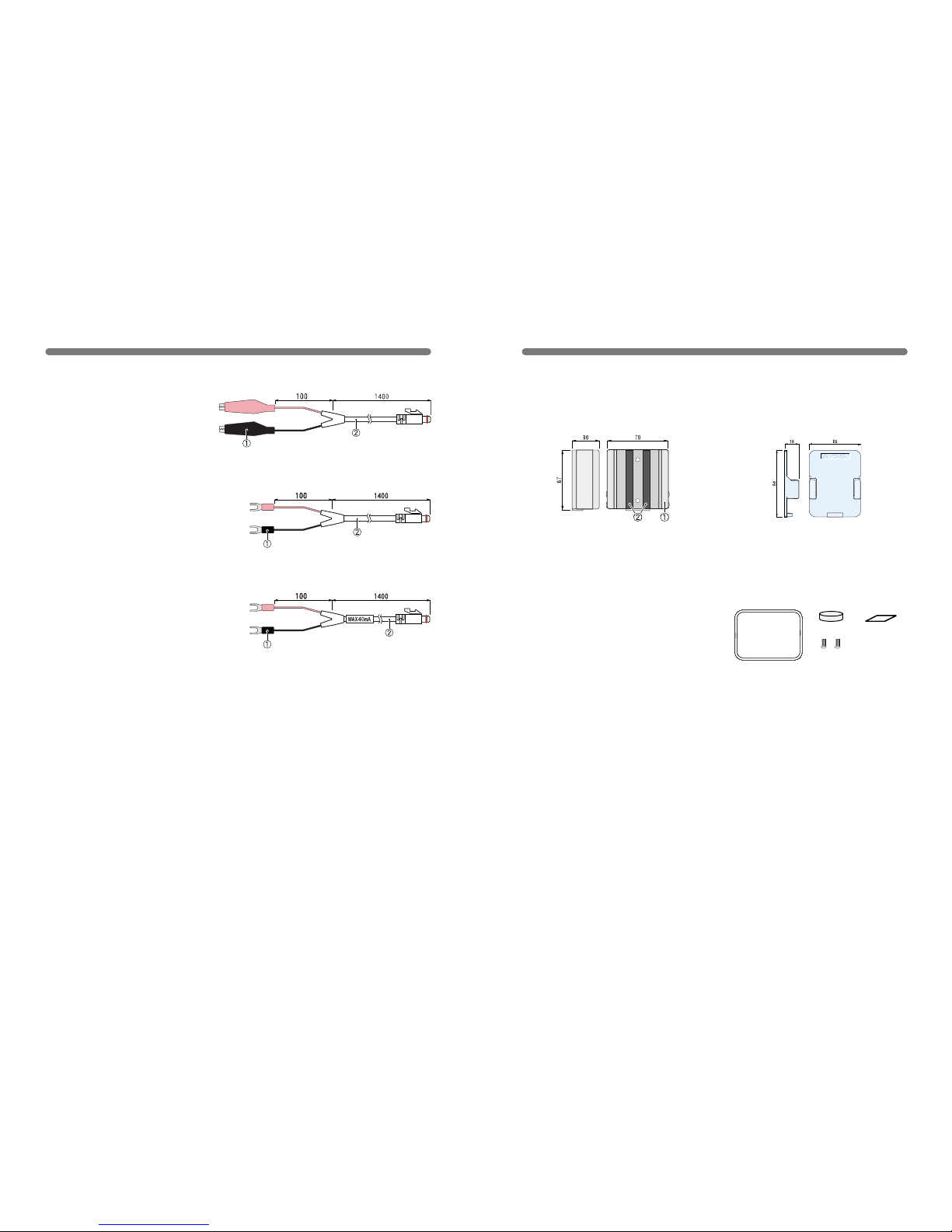
unit:millimeters
◆ Input Cable (for RVR-52)
RVR-7101 Input Cable
Cable Length: 1.5 m
Materials: ① Clip
② Vinyl Coated Electrical Wire
RVR-7102 Input Cable
Cable Length: 1.5 m
Materials: ① M3.5 Crimp Terminal
② Vinyl Coated Electrical Wire
RVR-7103 4-20mA Probe
Maximum Current Input:
MAX40mA
Interior Resistance: 100 Ω
Output: 2V at 20mA / 0.4V at 4mA
Conversion Accuracy: 0.5%
Cable Length: 1.5 m
Materials: ① M3.5 Crimp Terminal
② Vinyl Coated Electrical Wire
Input Cables (Optional)
68
◆ Wall Attachment
TR-05K2
Materials:
ABS Resin
TR-05K1
Screws x 2
Materials: ① Aluminum ② Neoprene
Options for TR-5/RTR-5/RVR-5
unit : millimeters
◆ Maintenance Set
Rubber Packig
Silicagel
Double Sided
Adhesive Tape
Lock Screw
TR-00P1
Contents: Rubber packing x 1
Silica gel x 1
Double-sided Adhesive tape x 1
Lock Screw x 2
Page 40

■
For product information or questions contact us at:
Ofce Hours:Monday to Friday 9:00-12:00/13:00-17:00
(GMT +9:00 Tokyo Time)
[Home Page / T&D Online]
We have opened an English Homepage called "T&D Online"
for your convenience. Here you can nd information about our
company, news, products, upcoming events, software and
user’s guides downloads, as well as, other support. Please
stop by and see what we have to offer.
http://www.tandd.jp/
This is printed on 100% recycled paper.
Published by T&D CORPORATION
Cop y r ight 20 0 1 -2003 T & D Corpo r a tion. A l l right s reserve d .
69
5652-169 Sasaga Matsumoto, Nagano Japan 399-0033
Tel: +81-263-27-2131
Fax: +81-263-26-4281
E-mail: [email protected]
Thermo Recorder RTR-57C User's Manual
 Loading...