

Page 1
© Copyright T&D Corporation. All rights reserved.
2016.12 16504820020 5th Edition
User’s Manual
Thank you for purchasing our product.
This manual provides explanations of the installation and
operation of the MCR-4V.
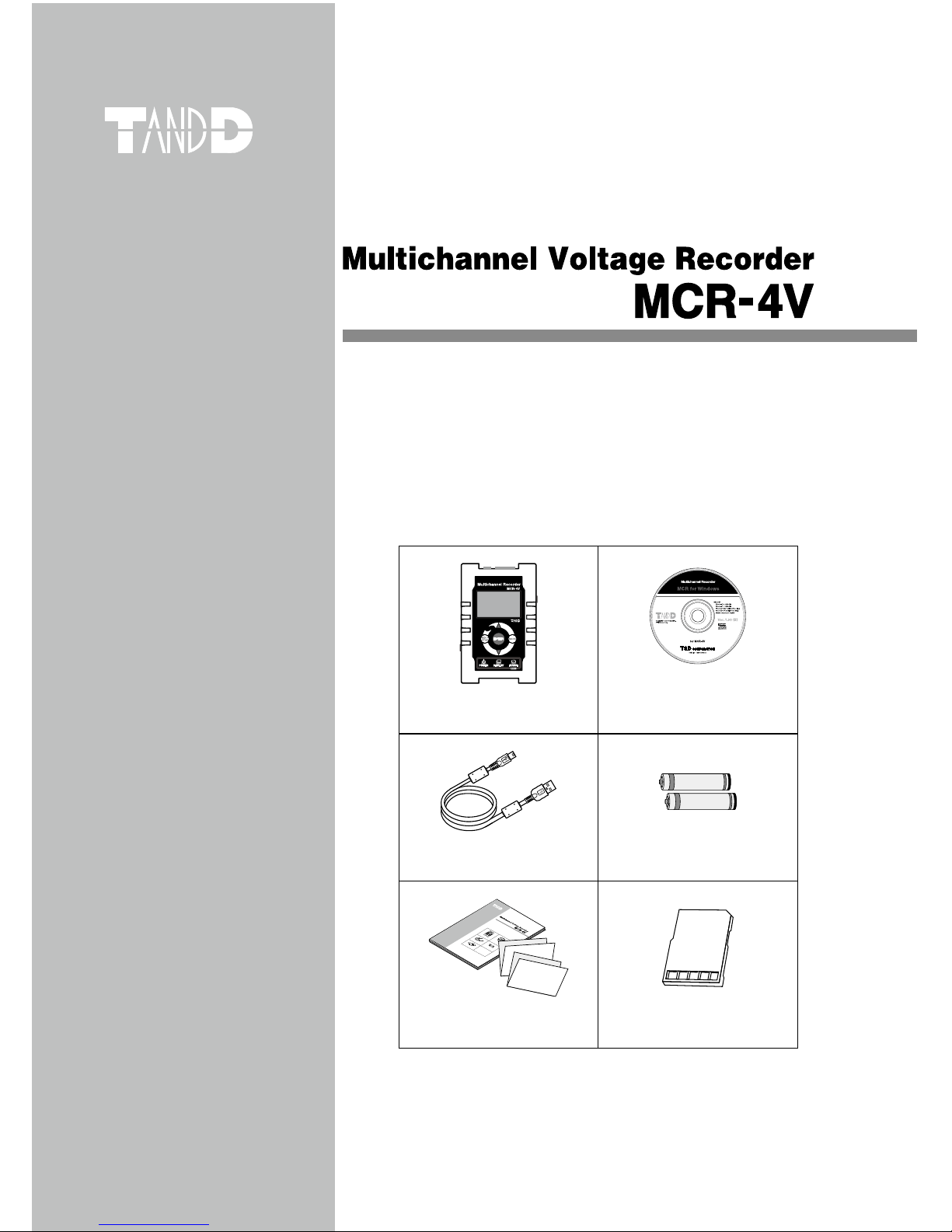
Please make sure the following items are included in the
package.
®
MCR-4V x 1 unit “MCR for Windows”
CD-ROM x 1
USB MIni-B Cable
(US-15C) x 1
AA Alkaline Battery (LR6)
x 2
© Copyright T&D Corporation. All rights reserved.
2013.04 16504820004(第2版)
取扱説明書
お買い上げありがとうございます。
本書ではMCR-4V本体の取り扱いおよび使用方法につい
て説明しています。
パッケージには以下の物が含まれています。すべて入っ
ているか確認してください。
®
MCR-4V 1台 MCR-4V for Windows
CD-ROM 1枚
USB通信ケーブル
US-15C1本
単3アルカリ電池
2本
取扱説明書・保証書(本書)
添付資料(2種) 各1部
User’s Manual Set
(Warranty Included)
Card Slot Cover x 1
Page 2

Important Notices and Disclaimers
In order to properly use this product, please carefully read all documents
that accompany the product before using. T&D Corporation accepts no
responsibility for any malfunction of and/or trouble with this product or
with your computer that is caused by the improper handling of this
product and will deem such trouble or malfunction as falling outside the
conditions for free repair outlined in the attached warranty.
- All rights of the attached documents belong to T&D Corporation. It is
prohibited to use, duplicate and/or arrange a part or whole of the
attached documents without the permission of T&D Corporation.
- Microsoft and Windows are registered trademarks of Microsoft Corporation in the United States and/or other countries.
- Windows Vista is either a registered trademark or trademark of Microsoft
Corporation in the United States and/or other countries.
- All registered trademarks, company names, product names and logos
mentioned herein or for products being used are the property of T&D
Corporation or of their respective owners.
- Specications, design and other contents outlined in the attached
documents are subject to change without notice.
- Please follow the safety precautions outlined in the attached documents
carefully. We cannot guarantee nor are we responsible for safety if this
product is used in any manner other than was intended.
- On-screen messages in the attached documents may vary slightly from
the actual messages.
- Please notify the shop where you purchased this product or T&D
Corporation of any mistakes, errors or unclear explanations in the
attached documents.
- T&D Corporation accepts no responsibility for any damage or loss of
income caused by the use of our product.
- Accompanying documents cannot be reissued, so please keep them in a
safe place.
- Please read the warranty and provisions for free repair carefully.
Page 3
1
Safety Precautions and Instructions
Safety Precautions and Instructions
The following items should be strictly obeyed for the safe usage of this
product, and for protecting yourself and other people from bodily harm
and/or damage to property.
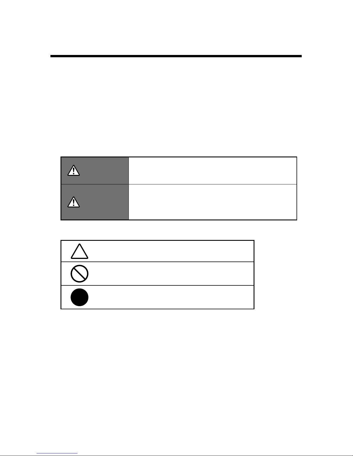
Explanation of Symbols
Warning Symbols
DANGER
Failure to follow the instructions with this symbol
could cause serious injury or even death.
CAUTION
Failure to follow the instructions with this symbol
could cause personal injury or physical damage
to equipment.
Picture Symbols
Denotes an important warning or caution.
Denotes a forbidden action.
Denotes an action that should be carried out.
Page 4
2
DANGER To Prevent Serious Accidents
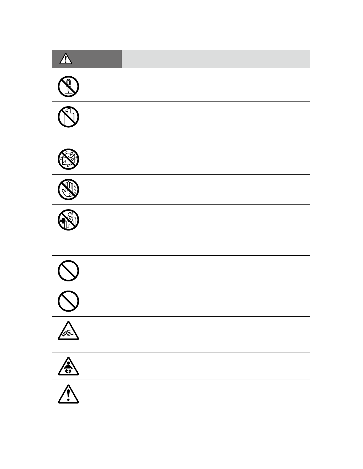
Do not disassemble, repair or modify the unit and accessories.
Do not use the unit in any environment that is exposed to
chemicals and harmful gases. Doing so may cause corrosion and/
or other danger to the unit. Also, coming in contact with hazardous
substances may cause bodily harm to the user or people nearby.
This unit is not water resistant. If water or a foreign object enters
the case, immediately unplug the AC adaptor and stop using it.
Do not handle the unit, remove batteries or cables with wet hands.
This product has been designed for private and/or industrial use
only. It should not be used in situations where strict safety
precautions are necessary such as with medical equipment, or in
systems directly or indirectly connected with human life or
well-being.
Do not drop or expose the unit to a strong impact.
Do not cut or process the cords for the communication cables.
Also, do not twist, pull on or swing any of the cords.
To prevent damage to the unit from static electricity, remove static
electricity from your body by touching metal around you (such as a
door knob and window frame) before touching the unit.
Place and store the unit and accessories out of the reach of
children.
Do not use any power, battery, sensor, or cable other than those
specied by T&D Corporation.
Page 5
3
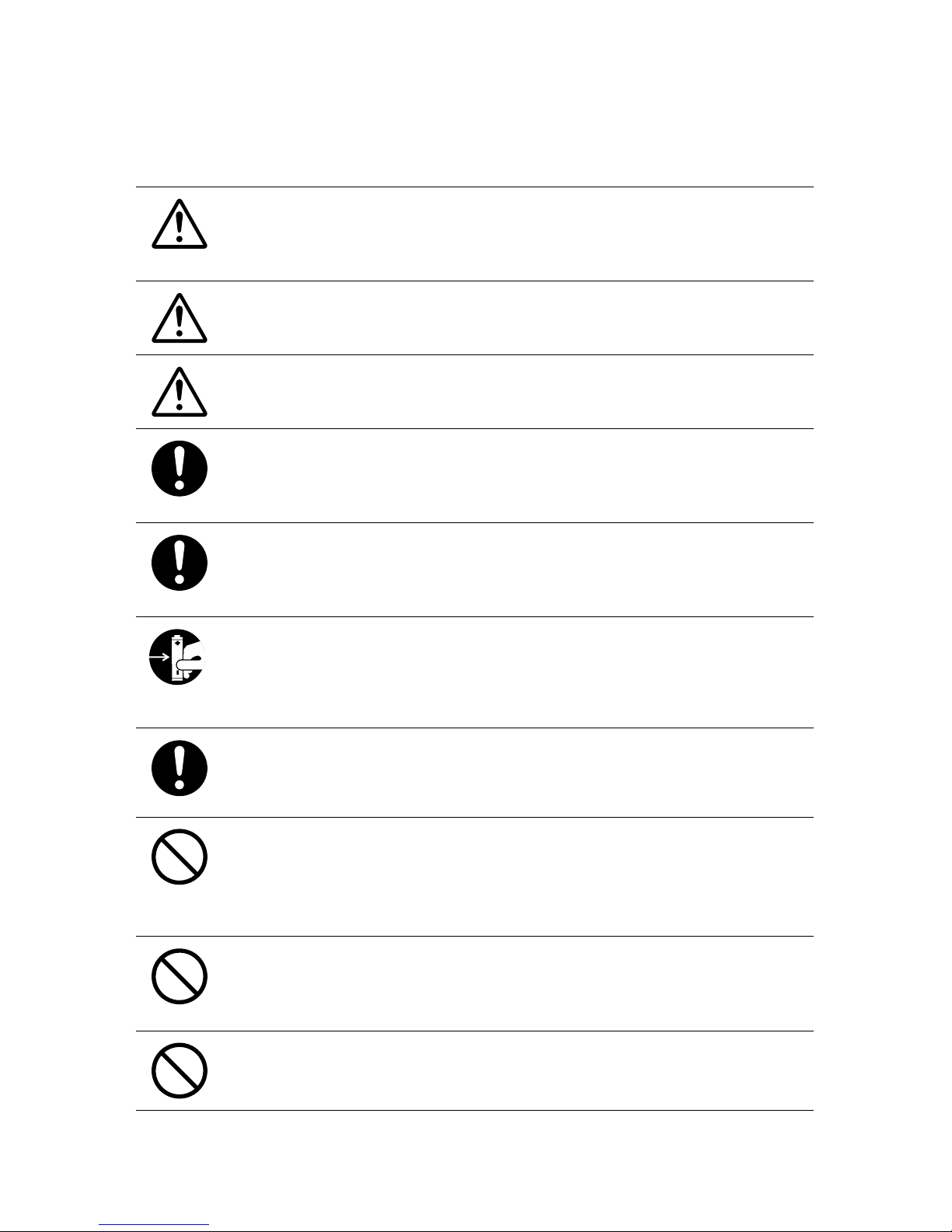
We are not responsible for any damage, malfunction or trouble,
whether direct or indirect, caused by the use of our product.
Do not put anything on top of the cable. This may cause overheating.
Do not disconnect the USB cable during USB communication.
Doing so may cause adverse effects to the unit and/or PC.
Make sure that all cable plugs are inserted fully, so as not to cause
an improper connection. Also, when unplugging the cable from the
unit, do not pull the cord, but hold the connector to disconnect.
If the unit produces heat, emits smoke or a strange smell, or makes
unusual noises, immediately remove the batteries, unplug the
power, and stop using it. Also, unplug the unit from the PC.
If the unit is not to be used for a long period of time, remove
batteries. If left in the unit, the batteries may leak and lead to
malfunctioning. Install new batteries when starting or re-starting to
use a unit.
If there is a possibility that high voltage pulses which exceed the
measurement range may be applied, make ground connections,
either directly or with the surge arrester.
Make sure that there is no magnetic media or materials within one
meter from the device.
Magnetic materials may cause damage to data stored in magnetic
media.
Do not remove the SD card or turn off the power while writing data
to the SD card. This may result in damage to data.
Do not apply voltages higher than ±50V to the earth or terminals. It
may cause electrication or malfunction.
Page 6
4
CAUTION Do not place or store in the following areas:
• Areas exposed to direct sunlight
• Areas exposed to excessive heat or high temperatures such as near re or
heating equipment
• Areas exposed to static electricity
• Areas exposed to strong magnetic elds
• Areas exposed to dampness
• Areas subject to condensation or wet areas
• Areas exposed to excessive vibration
• Areas exposed to excessive smoke, dust or dirt.
CAUTION Other Precautions
• Use the unit in the specied operating environment. Do not use it for any
purpose other than for which it was designed.
• Condensation may occur inside the case when a unit is moved from one
environment to another where there is a great difference in temperature.
• Do not use the unit in wet areas or places exposed to water such as
bathroom.
• When connecting the unit to your PC, make sure to follow all warnings
and directions from your computer manufacturer.
• We shall not guarantee the unit's operation if it has been connected to a
PC using a USB hub or a USB extension cable.
• Please take extra caution when plugging in and pulling out the USB plug
while another USB device such as CDD or HDD is in operation.
• Do not insert any foreign objects into any of the units' jacks.
• If the unit gets dirty, wipe it with a clean cloth.
• Make sure to remove dust and dirt from plugs of any cables.
• Battery terminals may provide insufcient contact due to age or vibration.
This may lead to data loss.
• If the unit is not to be used for a long period of time, for safety reasons
please remove the battery. If left in the unit, the battery may leak and lead
to malfunctioning.
• When an SD card is not inserted, insert the supplied card slot cover to
prevent the intrusion of dust.
Page 7

5
Before Using this Product
Please be careful about the procedures for Installation.
(For USB communication between your computer and a MCR-4V)
In order to use a USB connection to communicate between the unit and
a computer, it is necessary to install the software and the USB device
driver.
Make sure to rst install the software before connecting the unit to a
computer.
If you connect the unit rst, the USB device driver may not
be installed properly.
If you have connected the unit to your computer before installing the
software, make sure to click [Cancel] in the Wizard window when it
pops up on the computer display. Then disconnect the USB
communication cable from the unit.
Page 8

6
Table of Contents
Safety Precautions and Instructions ------------------------- 1
Before Using this Product ------------------------------------ 5
Overview
Appearance Diagram and Part Names ---------------------- 9
Touch Panel --------------------------------------------------------------10
Touch Panel Operation Methods --------------------------------------- 11
LCD Display and Icons -------------------------------------------------- 11
About How Data is Recorded -------------------------------- 14
Using SD Memory Cards ------------------------------------- 15
Supported Memory Cards ---------------------------------------------- 15
Using MCR-4V
Installing the Battery ----------------------------------------- 17
Usable Power Sources -------------------------------------------------- 17
Changing the Batteries --------------------------------------------------17
Measuring Voltage -------------------------------------------- 18
About the Measurements Display --------------------------------------18
About the Trend Graph Display ----------------------------------------- 19
Operating the Trend Graph --------------------------------------------- 19
Increasing Recording Channels ----------------------------- 21
About Group Recording with MCR-4V and MCR-4TC ---------------21
Storage Location for Group Recording --------------------------------22
Group Operations via Master ------------------------------------------- 23
Starting Recording by Group ------------------------------------------- 23
Stopping Recording by Group------------------------------------------24
About Menus
[Record Settings] Menu -------------------------------------- 26
[Data List] Menu ---------------------------------------------- 28
Displayed Items when Recording Stopped: ---------------------------28
Displayed Items during Endless Recording: ---------------------------29
[Memory Card] Menu ----------------------------------------- 30
[Operation Settings] Menu ----------------------------------- 30
Page 9

7
Overview Using MCR-4V
About Menus Using a PC with MCR-4V Other
Explanation of Items in Each Menu ------------------------- 31
[Record Settings] Menu Items ------------------------------------------ 31
[Data List] Menu Items (when recording stopped) -------------------- 38
How to Read Recorded Data Graph ----------------------------------- 39
[Data List] Menu Items (during endless recording) --------------------42
[Memory Card] Menu Items ---------------------------------------------44
[Operation Settings] Menu Items --------------------------------------- 45
Using a PC with MCR-4V
Installing the Supplied Software ----------------------------------------47
Connecting the Device to a PC ------------------------------ 49
Making Settings via PC -------------------------------------- 50
Channel Name -----------------------------------------------------------50
Scale Conversion Equation --------------------------------------------- 50
Unit Settings -------------------------------------------------------------50
Downloading Recorded Data to a PC ----------------------- 51
Download Recorded Data using “MCR for Windows”----------------51
Recorded Data File ------------------------------------------------------ 52
Download Recorded Data from all Connected MCR-4V Units-------53
Analyzing Recorded Data ------------------------------------ 54
Open Recorded Data ----------------------------------------------------54
Print Graphs ------------------------------------------------------------- 54
Other
Troubleshooting ----------------------------------------------- 55
Specications ------------------------------------------------- 60
MCR-4V ------------------------------------------------------------------60
Software (MCR for Windows) ------------------------------------------- 62
Page 10
8
Overview
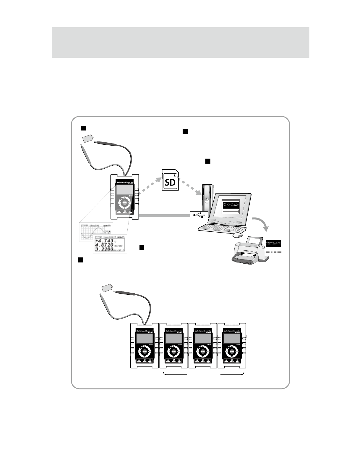
The MCR-4V is a multi-channel voltage data logger. It measures and
records voltage, and the data can be easily displayed in graph form,
enabling the immediate on-the-spot checking of continually-changing
data.
SD Memory Card
or
USB Connection
Measure and Record
Device Coupling
Image
Master
Slaves
Measurements
and Trend Graph
Use “MCR for Windows” for
- Device Settings
- Recording Settings
- Downloading Recorded Data
Use “T&D Graph” for
- Graph Display
- Data Analysis
-
Printing and Saving in Text
Main Features in Rec Settings
- Average Value Recording
- 50-60Hz Filter
- Increase of Number of Channels
- Preheat
- Recording Stop Trigger
Page 11
9
Overview
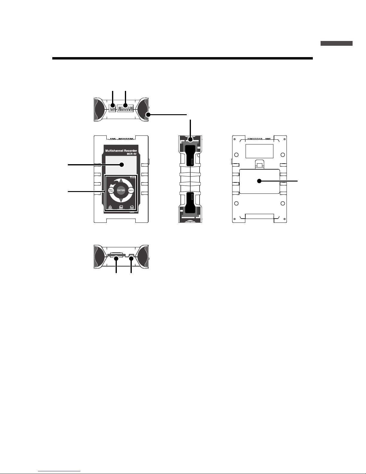
Appearance Diagram and Part Names
1. Preheat Terminal
2. Input Terminal
3. Coupling Lug
4. LCD Display
5. Touch Panel
(touchpad and control wheel)
6. SD Memory Card Slot
7. USB Port
8. Battery Cover
4.
5.
8.
3.
[TOP]
[FRONT] [SIDE] [BACK]
[BOTTOM]
2.1.
6. 7.
Throughout this manual, the MCR-4V is also referred to as “the device”
or “the unit”.
Page 12
10
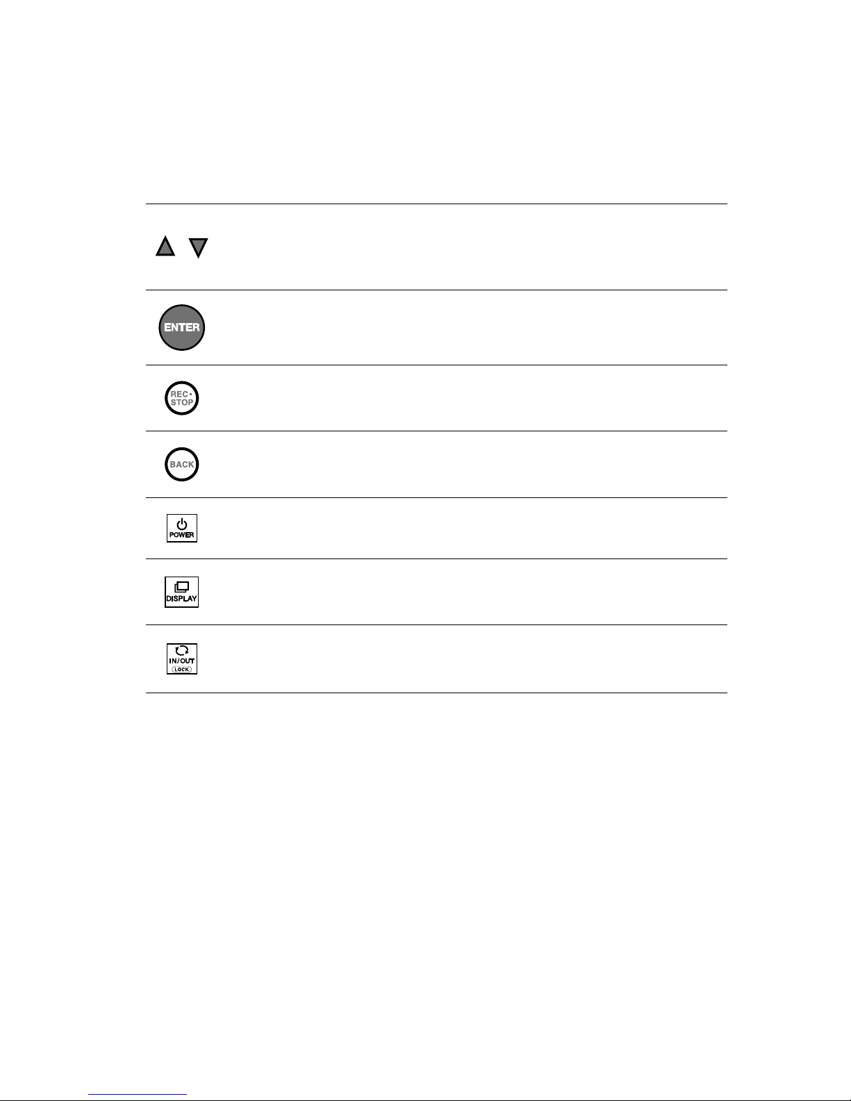
Touch Panel
Press to change the selected menu or settings item (by going
up or down), and to increase or decrease the values shown in
the LCD.
Press to conrm the selected menu, operation, or value.
Press to jump to the [Start Recording] or [Stop Recording]
menu.*
Press to return to the previous screen in the menu* or cancel
the current operation.*
Press and hold to turn the power ON/OFF.
Press to switch the display between [Menu] - [Measurements]
- [Trend Graph].
Press to switch between the touchpad operation and control
wheel operation. Press and hold to switch the key lock ON/OFF.
* Will not function when operating by control wheel.
Page 13
11
Overview
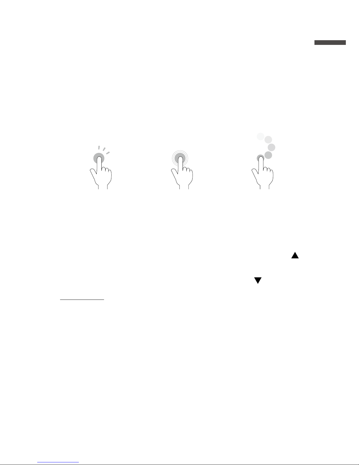
Touch Panel Operation Methods
There are two ways to operate the touch panel as follows:
- Touchpad operation
- Control wheel operation
Terms and gestures related to operations
Tap
(touch)
Tap desired area of
touch panel.
Press-and-hold
(hold down)
Touch the screen and
hold nger in place
for a few seconds.
Mainly used to switch
ON/OFF the power
and key lock.
Control Wheel
Operation (rotate)
Press and rotate the
control wheel (white
circular area).
Clockwise
movement moves
(up) and counterclockwise movement
moves
(down).
IMPORTANT
- During operation, if none of the above gestures are performed for a while, the operation
will be canceled and the screen will return to the original value or previous screen.
- Make sure to use a bare nger to operate the touch panel. If you use the tip of your
ngernail, gloves, or touch pen, touch panel operations may not be recognized.
Auto Power Off Function
If the device is not used for about three minutes, it will automatically turn
off to save battery power. However, the Auto Power Off function will be
disabled in any of the following situations.
- When a recording session is in progress
- When measurements or trend graphs are displayed on the screen
- When running on external power
Page 14
12
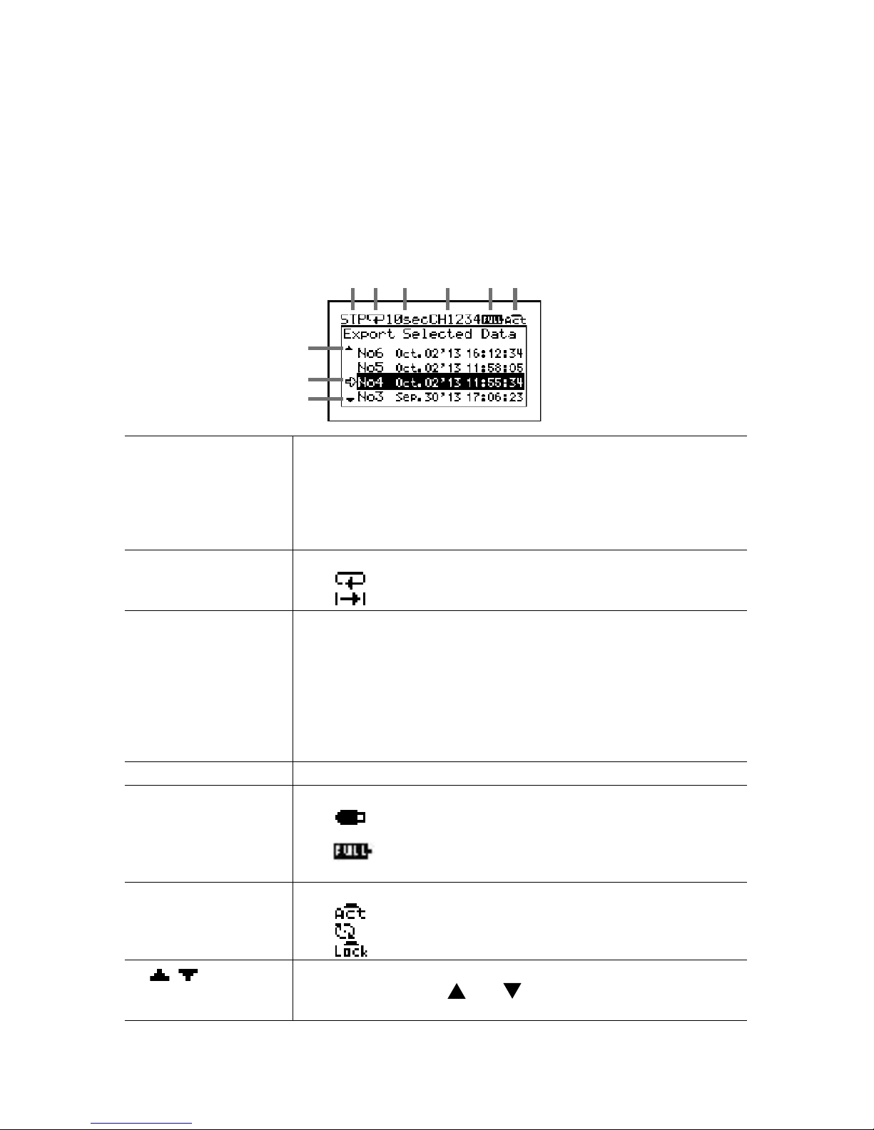
LCD Display and Icons
The following contains some brief explanations about icons. Each menu
will be explained later in the “Menu List” pages.
A highlighted display
shows the item currently
selected, and a blinking
highlight shows that an
item is being changed.
LCD backlight will be
ON during operation.
7
8
7
1 2 3 4 5 6
1 Recording Status Shows the recording status.
REC : Recording in progress
STP : Recording stopped
PRG : Waiting for programmed start
IMM : Preparing immediate start
TRG : Stopped by trigger
2 Recording Mode Shows the recording mode.
: Endless mode
: One-Time mode
3 Recording Interval Shows the recording interval.
ms : millisecond(s)
sec : second(s)
min : minute(s)
When the recording method is Average, “Aver.” and the
recording interval are displayed alternatingly.
When the recording method is Ave.Fine, “Ave.f” and the
recording interval are displayed alternatingly.
4
Recording Channels
Shows the channel(s) being measured and recorded.
5 Battery Mark Shows source of power and battery level
/ Battery Mark (Alternating Display) : Running on
external power
Battery Mark only (see the next page) : Running
on battery
6 Operation Mode Shows the operation mode status.
: Touchpad operation enabled
: Control wheel operation enabled
: Touch Panel disabled
7
These indicate that there are more menu items above or
below for view. Use
and on the touch panel to scroll
up and down.
Page 15
13
Overview
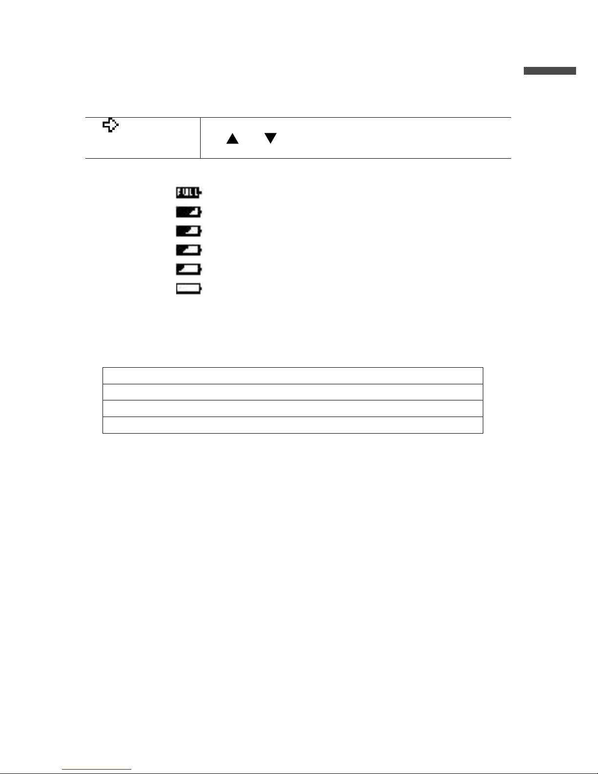
8 An item marked with an arrow denotes it has been selected.
Use
and on the touch panel to move the arrow up and
down. Press <ENTER> to execute the selected operation.
The battery mark shows the battery level as follows.
: Full or near full power
: Beginning to lose power
: Signicant loss of power
: Change batteries as soon as possible
: Change batteries immediately
: Not operable with batteries only
Below are some examples of recording conditions and the
corresponding estimated battery life.
4 channels, Instantaneous value, 10-ms interval : About 4.5 days
4 channels, Instantaneous value, 1-sec interval : About 120 days
4 channels, Instantaneous value, 10-sec interval : About 150 days
Power OFF : About 3 years
* Battery life varies depending upon the measurement conditions, operating
environment, and battery performance.
Page 16
14
About How Data is Recorded
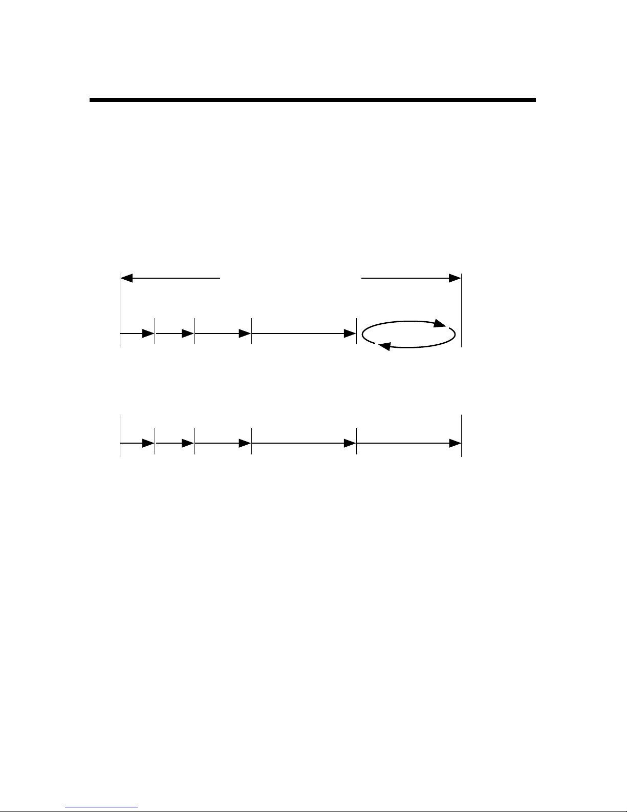
The MCR-4V records measurement data to its internal memory. A
recording session is one cycle from recording start to stop, and the
MCR-4V can record multiple sessions. The number of recording
sessions and number of data readings which can be recorded depends
upon the number of channels, the recording interval and other settings.
In the “n”th recording session, the remaining memory space is used for
recording.
EX: When logging capacity is lled during the 5th recording session:
1st
1st
2,000
readings
2,000
readings
2nd
2nd
3,000
readings
3,000
readings
3rd
3rd
5,000
readings
5,000
readings
4th
Internal Memory Capacity
4th
8,000
readings
8,000
readings
In Endless mode,
data will be overwritten from the
beginning of the 5th recording
session and recording will continue.
In One-Time mode,
recording will stop.
5th
5th
* If the memory capacity has not reached full, up to 30 recording sessions can be
made.
Page 17
15
Overview
Using SD Memory Cards
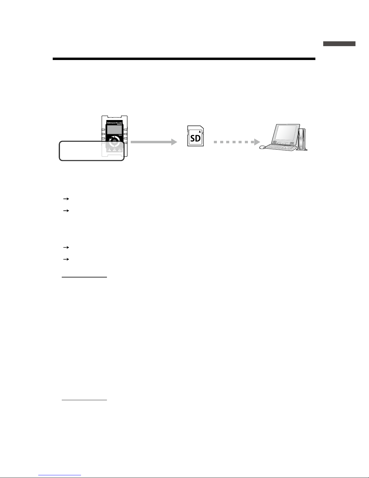
It is not only possible to transfer data stored in the internal memory to
an SD memory card, but it is also possible to automatically backup data
while recording in endless mode. Operations related to the use of an SD
memory card are as follows:
Record in internal
memory
Copy data to a
memory card
Copy
to a PC
Exporting Data while Recording is OFF (Manual Saving) See p.38 for
details
[Data List]—[Export Selctd Data]
[Data List]—[Export All Data]
Exporting Data while Endless Recording is ON (Manual Saving /
Automatic Saving) See p.42 for details
[Data List]—[Expt Curr Data Now]
[Data List]—[Auto Data Export]
IMPORTANT
- Memory cards are not included. Please purchase separately.
- Measurement data cannot be directly recorded into a memory card.
- Before inserting an SD memory card into the device, make sure to switch off write
protection on the memory card.
- Exporting data to the memory card will not erase it from the device’s internal memory.
Delete recorded data in the device as necessary.
Supported Memory Cards
- SD Memory Cards
- SDHC Memory Cards
IMPORTANT
- SDXC memory cards cannot be used.
- It is possible to run a quick test to see if your memory card works in. See p.44 for details.
Page 18

16
Using MCR-4V
The following shows the basic ow of procedures.
4.
Measuring and Recording
5.
Viewing Recorded Data in Graph on the Device (see p.39)
Use MCR-4V Use PC
3.
Setting up the Device (see p.30)/ Making Recording Settings (see p.26)
* Recording Settings can be made both on the device and from a PC.
2.
Getting PC Ready
Install the provided software (see p.47)
Connect the device to a PC (see p.49)
1.
Getting Device Ready
Install the batteries (see p.17)
6.
Downloading Recorded Data to a PC
Exporting data to an SD memory card and transferring to a PC. (see p.38)
Using the supplied software “MCR for Windows” (see p.51)
* Either of the above can be used to download recorded data to a PC.
7.
Analyzing Recorded Data on a PC (see p.54)
View Graph, Print, Save in Text
When not using a PC, the only necessary steps are 1 and 3 to 5.
Page 19
17
Using MCR-4V
Installing the Battery
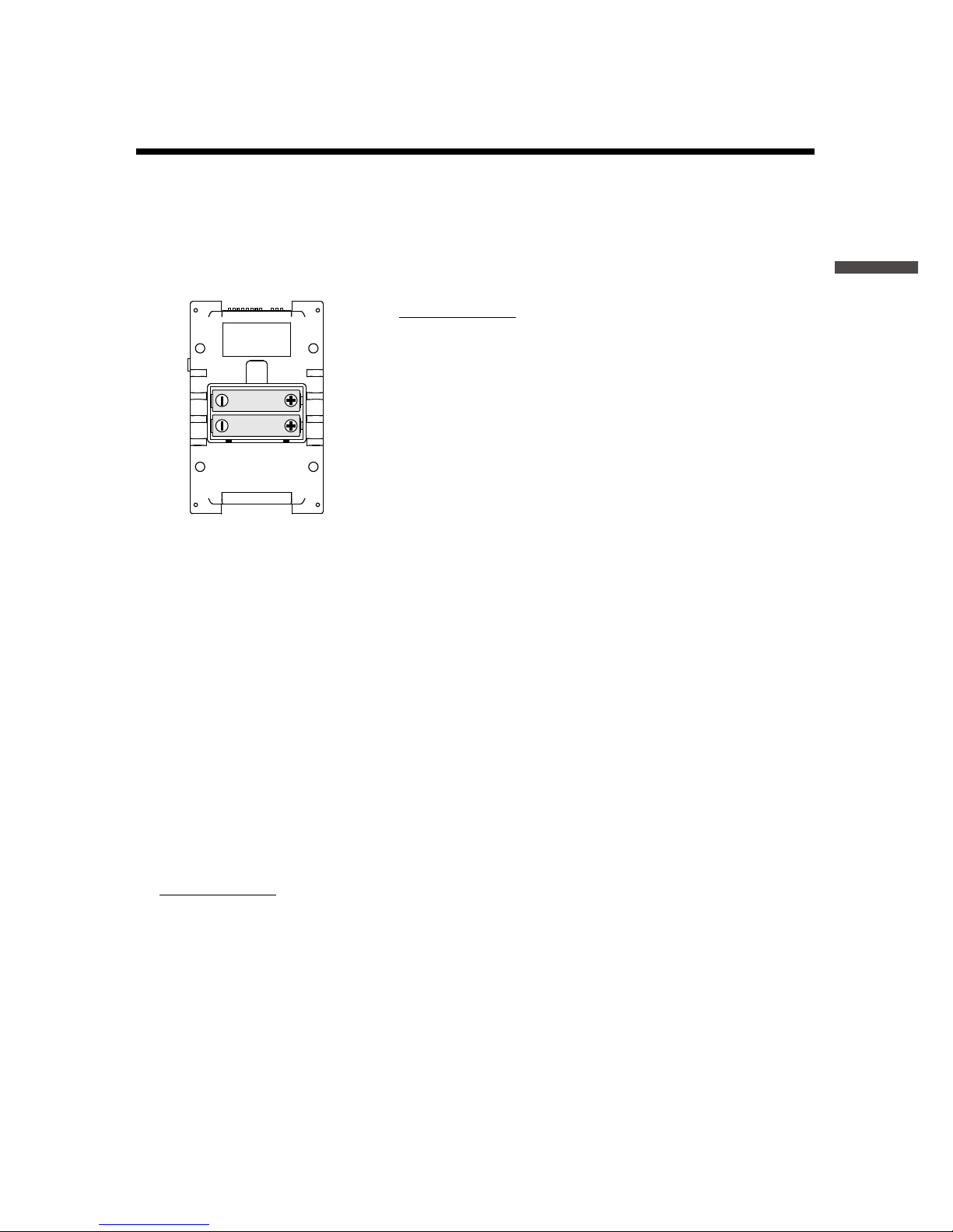
Remove the battery cover from the back of the device, and insert the
supplied two AA alkaline batteries as shown in the gure below.
After the batteries are inserted, the [Please set the clock] message will
appear on the LCD.
IMPORTANT
- Make sure to use new batteries of the same kind.
- Make sure not to mistake + / -.
- Do not insert or change batteries with wet hands.
- Be sure to completely close the cover.
- The MCR-4V cannot recharge batteries.
Usable Power Sources
- AA Alkaline Batteries
- AA Ni-MH Batteries
- AC Adapter (USB type)
- USB Bus Power
Changing the Batteries
If the battery runs down before it is replaced, MCR-4V will automatically
stop recording to protect data. Check the battery mark (see the previous
page) and change batteries as necessary.
IMPORTANT
- To protect data, please stop recording rst before changing batteries. Not doing so
may result in loss of data being recorded.
- When you wish to replace batteries while recording is in progress, make sure to
connect the USB cable to your PC for USB bus power.
- If the MCR-4V runs out of power while processing data on a SD memory card, the data
on the card may be corrupted.
Page 20
18
Measuring Voltage
1.
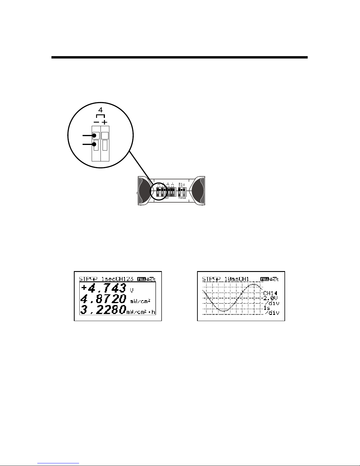
Connect the item to be measured to the MCR-4V using a compatible
wire.
1. Prepare a compatible 10mm strip wire (see
Spec).
2. Using a screwdriver or other such tool, while
pressing down on the terminal button <B>
on the top of the device, insert the wire into
the hole <A>.
3. When removing the wire, push down on <B>
and gently pull the wire out of the hole <A>.
Enlarged View of
Input Terminal
Top Surface
A
B
* Absolute maximum input voltage is 50V.
* Maximum measurable input voltage is ±24V.
2.
Press <DISPLAY> to switch the LCD display, and view the
measurement and/or trend graph.
Measurements Trend Graph
About the Measurements Display
The font size used to display the measurement automatically changes
depending on the number of channels.
* You can change the number of channels by going to the Main Menu and selecting
[Record Settings] > [Rec.Channel]. To change the [Rec.Channel] setting, [Detailed
Sett.] needs to be set to ON.
* When using the scale conversion, the converted value and unit are displayed.
Page 21
19
Using MCR-4V
* You can switch the Scale Conversion ON/OFF by going to [Record Settings] and
selecting the desired channel settings (see p.33 “CH1 Settings - CH4 Settings”). Also,
the scale conversion equation can be changed via “MCR for Windows”.
About the Trend Graph Display
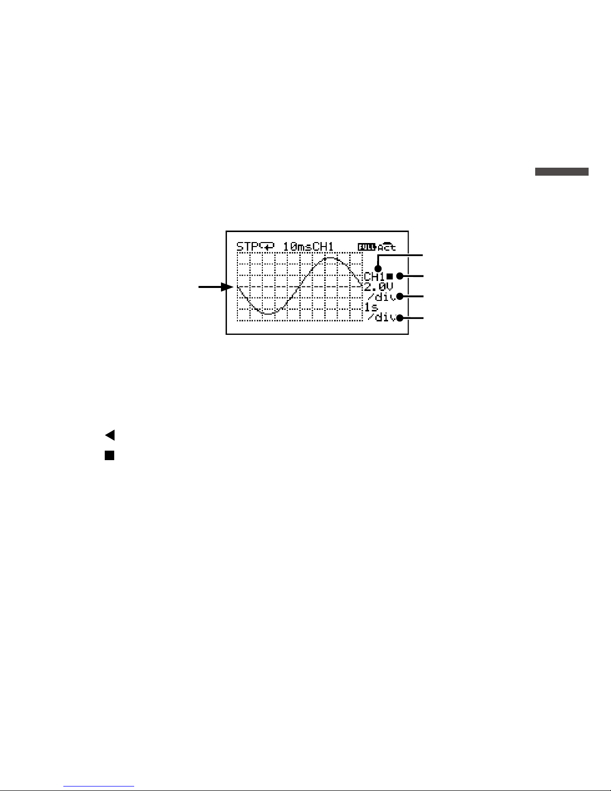
A trend graph is displayed for each channel of data.
1.
2.
3.
4.
The ------ line located
in the center indicates
0V (zero volt).
1. Channel for Display
The channel for display can be changed.
Select the measurement channel to view the graph.
2. Scrolling Method
: Scrolls graph and divisions together.
: Scrolls graph only.
* The scrolling method can be switched with <ENTER> when none of 1 to 4 in the
above diagram are highlighted or ashing on the LCD.
3. Vertical Voltage Scale (volts/div)
Specify the value for each vertical division in V or mV.
EX) “2.0V/div” shows that each vertical division represents 2.0 V.
4. Horizontal Time Scale (time/div)
Specify the value for each horizontal division in sec or min.
EX) “1s/div” shows that each horizontal division represents 1 sec.
* 4.
The possible selections for the time scale will change depending on the
measurement interval.
Page 22

20
Operating the Trend Graph
Use and to highlight the desired item, and tap <ENTER>. While the
selected item is blinking, use
and again to change the value, and
tap <ENTER>.
* If no operations are performed or a change is not conrmed with <ENTER> while the
selected item is blinking, the operation will be canceled and the selected item will
return to the original value.
Page 23
21
Using MCR-4V
Increasing Recording Channels
Up to four units can be coupled together to allow for a maximum of 16
channels.
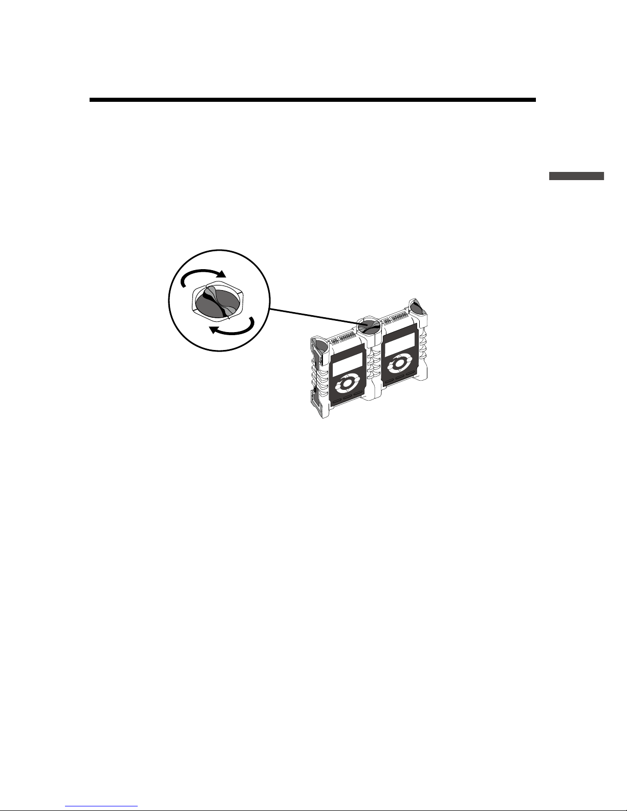
When the bodies of multiple units are connected, the MCR-4V at the far
left side will be automatically designated as the Master and all other
connected MCR-4V units will be designated as Slaves.
Coupling Image
Turn clockwise.
Slave
Master
By starting recording on the Master unit, all connected Slave units will
start recording at the same time.
Coupling of MCR-4V and MCR-4TC is possible. Refer to the MCR-4TC
User’s Manual for its operating instructions.
About Group Recording with MCR-4V and MCR-4TC
When using MCR-4V as the Master and MCR-4TC as the Salve:
- The measurement interval of the Slave is determined by the Master, but,
Group Recording cannot be started if the measurement interval is less
than 100ms.
When using MCR-4TC as the Master and MCR-4V as the Slave:
- The measurement interval of the Slave is determined by the Master.
- The 50-60Hz Filter will be set to ON when recording interval is 500ms or
greater, and set to OFF when recording interval is less than 500ms.
Page 24
22
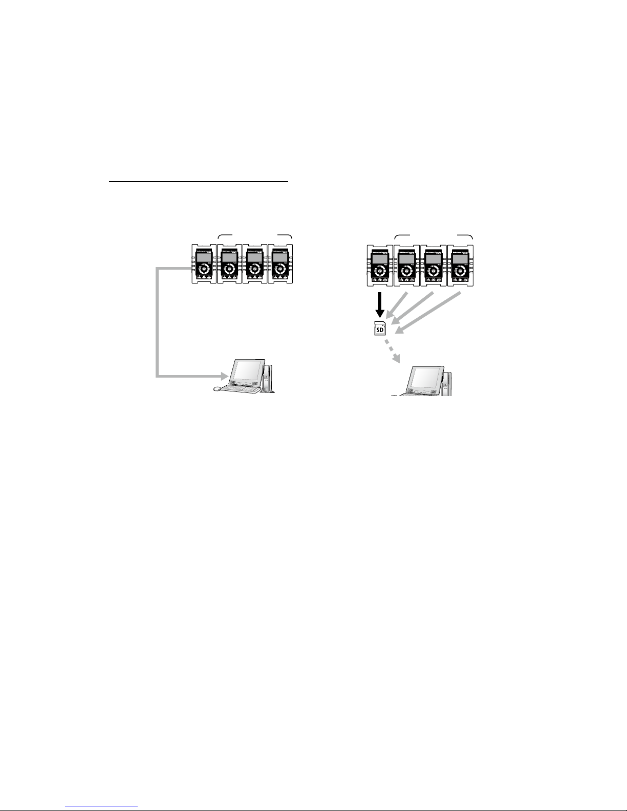
Storage Location for Group Recording
When performing a group recording for multiple units, recorded data will
be stored in each unit's memory. To analyze recorded data on a PC,
either download data using “MCR for Windows”, or export data to the
SD memory card to transfer to a PC.
“MCR for Windows” also
makes it possible to download
recorded data from Master and
all Slave units together.
Slaves SlavesMaster Master
* All recorded data les downloaded using “MCR for Windows” will be stored in the
same folder by default. See p.52 for the storage location of recorded data and le
name.
Page 25
23
Using MCR-4V
Group Operations via Master
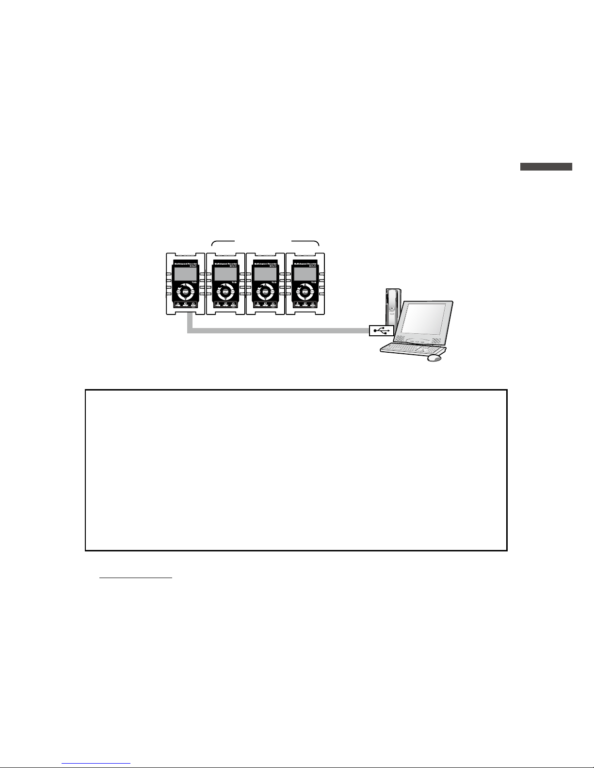
Group operations such as the starting and stopping recording for the
connected units can only be performed via the Master. Upon the start of
a group recording, the main recording settings will be temporarily
copied to all connected Slaves. Upon the stopping of recording, all
copied settings will be returned to their original state.
Using “MCR for Windows”, it is possible to start
and stop recording by group by connecting the
Master to a PC via USB.
SlavesMaster
Settings Controlled by the Master:
Settings for Recording Mode, Recording Method, 50-60Hz Filter,
Recording Interval, and Recording Channels
Settings not Controlled by the Master:
Settings for Channel Name, Measurement Range, Scale Conversion
and Warning Monitoring
Other Settings:
Preheat and Recording Stop Trigger are only enabled on the Master.
IMPORTANT
- Operations related to the SD memory card (such as Data Export and Quick Format)
cannot be performed by group via the Master.
- To change settings for items that are not controlled by the Master, either change on the
target connected Slave unit, or use “MCR for Windows” by connecting each Slave unit
to the PC with a USB cable.
- Among the above “Settings not controlled by the Master”, the Channel Name and
Scale Conversion can only be set or changed via “MCR for Windows”.
Page 26

24
Starting Recording by Group
1.
Make recording settings for each device separately; no matter if it is a
Master or a Slave.
* See p.26 for a list of the possible setting items.
* See p.23 for the settings that are/are not controlled by the Master.
2.
From the main menu of the Master, select [Record Settings] - [Start
Recording].
3.
For the [Method], select [IMMED (grp)] or [PGM (grp)].
4.
Select [OK] and tap <ENTER>.
IMPORTANT
All connected Slaves need to have power switched to ON.
Stopping Recording by Group
From the main menu of the Master, select [Record Settings] - [Stop
Recording].
IMPORTANT
- During Group Recording, if the bodies of the devices are disconnected from one
another, recording will continue on the Master but will stop on the Slave units.
- Even when devices are coupled, power will not be supplied from the Master to any
connected Slave units.
- When the Master stops recording, all Slaves will stop recording.
- During recording in one-time mode, if the Slave's memory capacity becomes full,
recording will stop on that Slave unit only.
Page 27

25
Using MCR-4V
Page 28
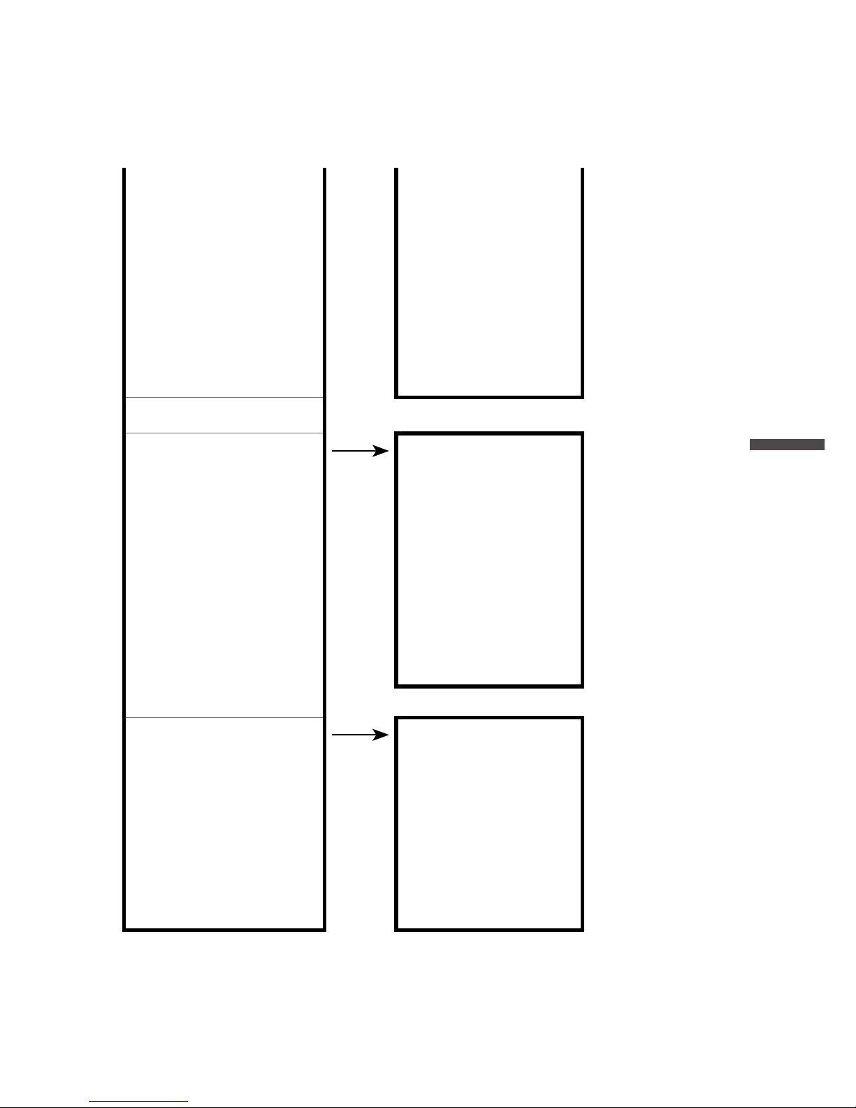
26
About Menus
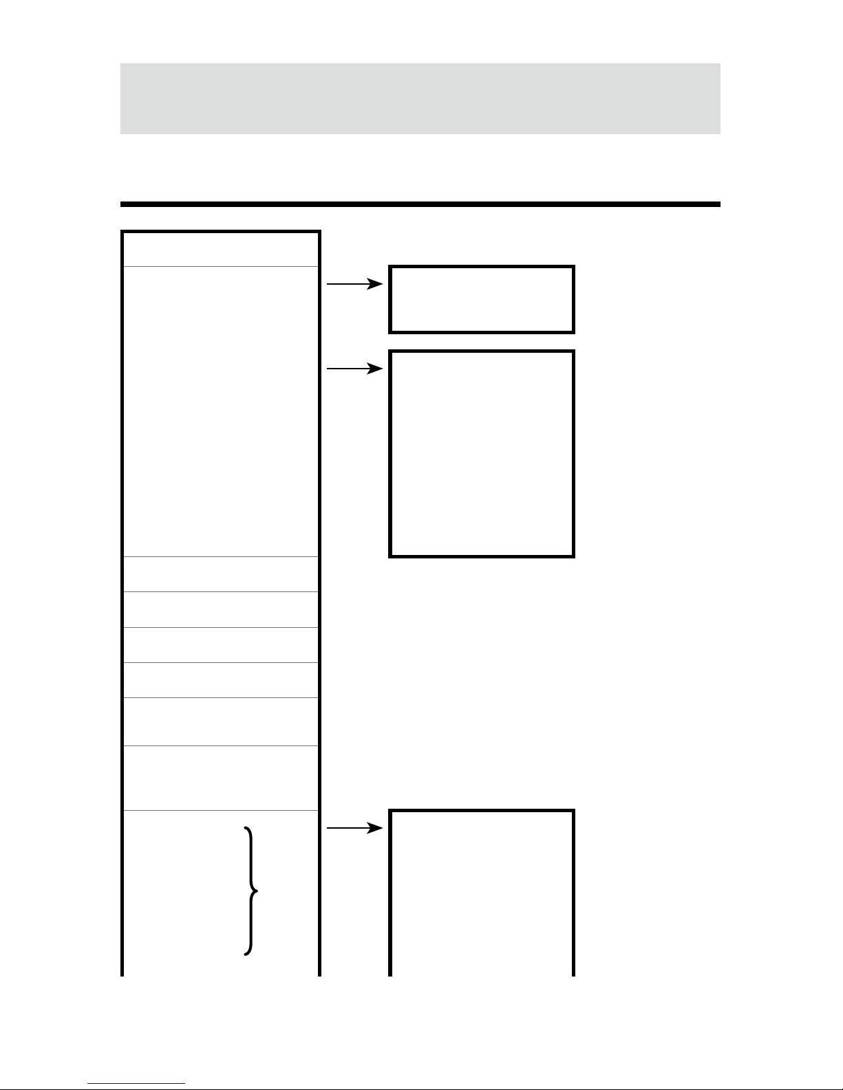
[Record Settings] Menu
[Back]
Stop Recording
[Back]
OK
Start Recording
[Back]
OK
Method : IMMED (indv) IMMED (indv) /
PGM (indv) /
IMMED (grp) /
PGM (grp)
Month/Day/Year
HH:MM:SS*
1
Detailed Sett.: OFF ON / OFF
Rec.Mode : Endless Endless / One Time
Rec.Method : Instant*
2
Instant / Average / Ave.Fine
50-60 Hz Filter : ON*
2
ON / OFF
Rec.Interval: 10 sec 2 / 5 / 10 / 20 / 50 / 100 / 200 / 500ms / 1 / 2 / 5 / 10 /
15 / 20 / 30sec / 1 / 2 / 5 / 10 / 15 / 20 / 30 / 60min
Rec.Channel : CH1234*
2
CH1 / CH2 / CH3 / CH4 / CH12 / CH23 / CH34 /
CH13 / CH24 / CH14 / CH123 / CH234 / CH124 /
CH134 / CH1234
CH1 Settings
[Back]
CH2 Settings Meas.Range : ±24V ±300mV / ±1.5V /
±6V / ±24V /
Auto*
2
CH3 Settings Scale Conv. : OFF ON / OFF
CH4 Settings Eq. y=1.0x+0.0
Page 29
27
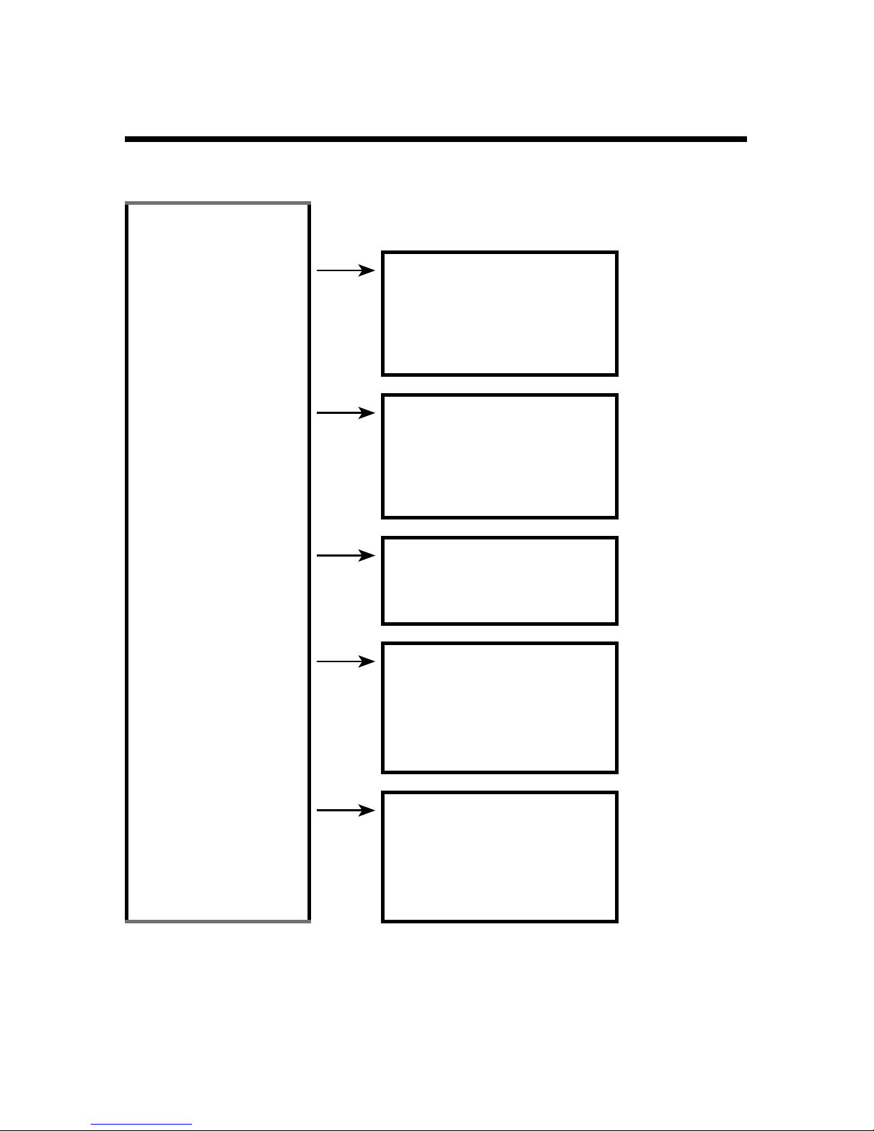
About Menus
Unit [ V ]
Warn Montr : OFF OFF / Lower /
Upper / Up&Low
Uppr Limit : - - -*
3
User Specied
Voltage Value
Lwr Limit : - - -*
3
User Specied
Voltage Value
Judge Time : - - -*
3
User Specied
Time
Preheat : OFF OFF /User Specied Time
Rec.Stop Trigger
[Back]
Function : OFF ON / OFF
Channel : - - - CH1 / CH2 / CH3
/ CH4
Slope : - - - Rising / Falling
Voltage : - - - User Specied
Value
Stop in : - - - User Specied
Time
Save/Restore Sett.
[Back]
Save Settings1
Save Settings2
Save Settings3
Save Settings4
Restore Settings1
Restore Settings2
Restore Settings3
Restore Settings4
*1: Will only appear when the recording start method is set to PGM (programmed start).
*2: Will not appear when Detailed Sett. is set to OFF.
*3: Will not appear when Warn Montr (warning monitoring) is set to OFF.
Page 30
28
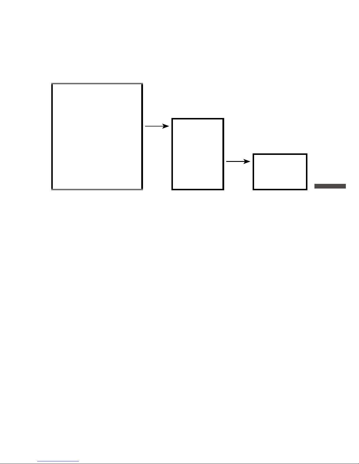
[Data List] Menu
Displayed Items when Recording Stopped:
[Back] * List number, date, and time shown below are
examples.
Display Graph
[Back]
No4 Jul 30 ’13 16:19:45
No3 Jul 29 ’13 15:42:51
…
Export Selctd Data [Back]
No4 Jul 30 '13 16:19:45
No3 Jul 29 '13 15:42:51
…
Export All Data [Back]
OK
Delete Selctd Data
[Back]
No4 Jul 30 '13 16:19:45
No3 Jul 29 '13 15:42:51
…
Delete All Data [Back]
On This Device Only
On All Devices*1
*1: When selecting [Delete All Data] on the Slave unit, the [On All Devices] option will not
appear.
Page 31
29
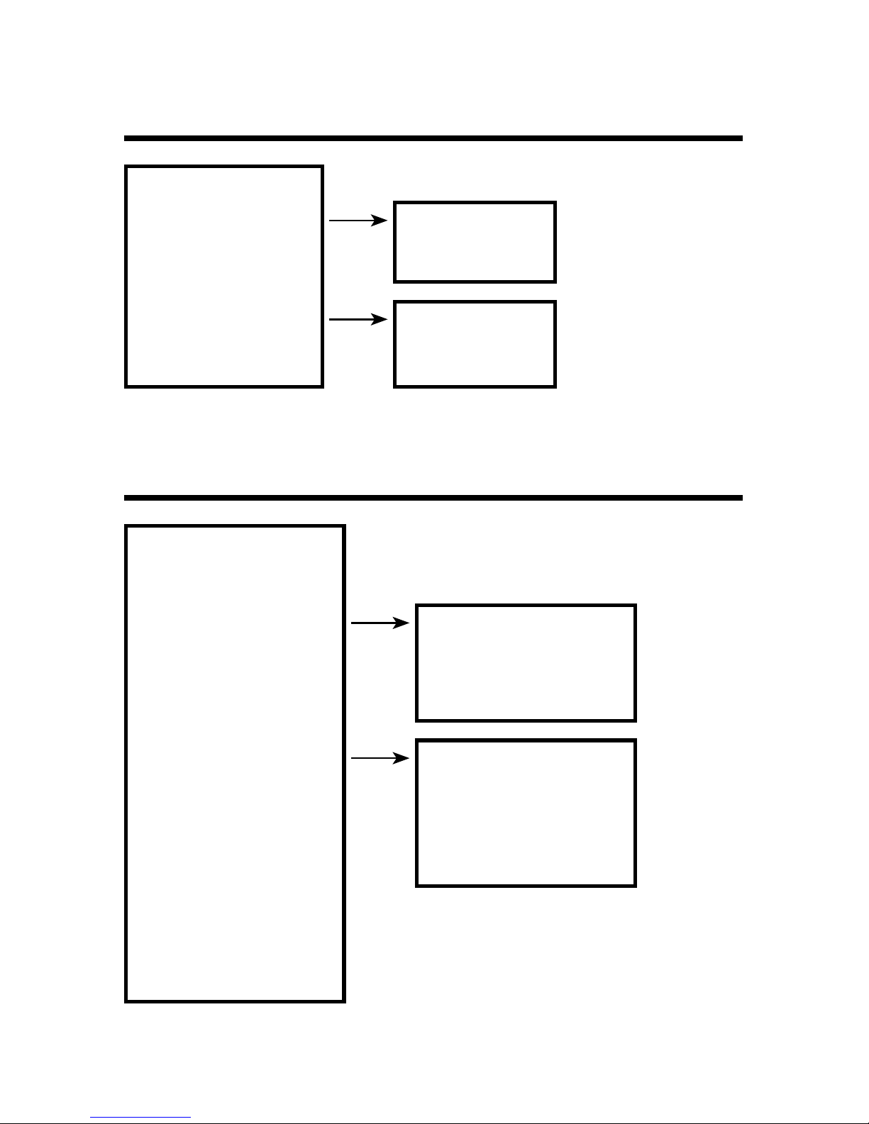
About Menus
Displayed Items during Endless Recording:
[Back]
Expt Curr Data Now
Formatted & Blank Card?
Auto Data Export*1
[Back]
Yes
Quick Format
No
[Back]
OK
*1: When recording in one-time mode, [Auto Data Export] will not be displayed.
Page 32
30
[Memory Card] Menu
[Back]
Quick Format
[Back]
OK
Memory Card Test
[Back]
OK
[Operation Settings] Menu
[Back]
Set Contrast : 65 0 to 100
Check Memory [Back]
Memory :
Data :
Set Clock
[Back]
July/31/'13 16:43:22
Time Zone GMT+09:00
DST
00:00
Beep : ON ON / OFF All / OFF Click
Key Lock : OFF OFF / 240 to 5sec
Return to Default
Page 33
31
About Menus
Explanation of Items in Each Menu
[Record Settings] Menu Items
[Stop Recording]
Click [OK] to stop recording.
[Start Recording]
Click [OK] to start recording.
[Method : IMMED(indv) / PGM(indv) / IMMED(grp) / PGM(grp)]
IMMED(indv) : Starts recording immediately.
PGM(indv) : Starts recording on the specied date and time.
IMMED(grp) : Starts Group Recording immediately.
PGM(grp) : Starts Group Recording on the specied date and time.
For details about Group Recording, see p.21.
[Detailed Sett.: ON / OFF]
Switch ON/OFF the detailed settings.
When detailed settings is switched to OFF, the [Rec.Method], [50-60Hz
Filter], and [Rec.Channel] menus will not appear on the screen, and the
following limitations will be placed on the settings.
Rec. Method
(nondisplay)
Fixed to “Instant” (Instantaneous Value)
50-60Hz Filter
(nondisplay)
Fixed to OFF when recording interval is 10ms - 200ms, and
xed to ON when recording interval is 500ms - 60min.
Rec. Interval Not possible for under 10ms
Rec. Channel
(nondisplay)
Fixed to 4 channels (CH1234)
Meas. Range Not possible to select “Auto”
[Recording Mode : Endless / One Time]
Endless: When the internal memory capacity becomes full, the most
recent data will be overwritten and recording will continue.
Onetime: Recording will be stopped at the moment the internal memory
capacity becomes full.
* See p.14 for an outline of info about recording and memory.
Page 34

32
[Rec.Method: Instant / Average / Ave.Fine]
Select the recording method to be used. For information about the
sampling interval when recording average values, see the attached
document “Sampling Interval for Recording Average Values”.
Instant (Value): Records the instantaneous value at the set recording
interval.
Average (Value): Records the value as the average of the measurements
taken during the set recording interval.
Ave.(Value) Fine: This records the average value for measurements at
even shorter measurement interval.
IMPORTANT
- When recording average values, the rst recorded value is invalid because an average
cannot be calculated.
- If the Preheat function has been set to ON, then only recording of instantaneous values
can be selected.
- Recording in the “Ave.Fine” method consumes more power than other methods,
resulting in a shorter battery life.
[50-60 Hz Filter : ON / OFF ]
Switch ON/OFF the lter function to eliminate 50-60Hz noise.
* This setting will affect both the shortest possible recording interval and battery life.
[Rec. Interval : (user-specied time)]
Select from 23 choices: 2, 5, 10, 20, 50, 100, 200, 500 msec. / 1, 2, 5, 10,
15, 20, 30 sec. / 1, 2, 5, 10, 15, 20, 30, 60 min. (default setting is 10 min)
However, available choices will differ depending upon the combination of
other settings.
[Rec. Channel : ]
Select the channel(s) for recording. It is possible to select to record using
one channel or a combination of channels from Ch1 - Ch4. The number of
channels which can be selected will differ depending upon the combination of other settings.
Page 35
33
About Menus
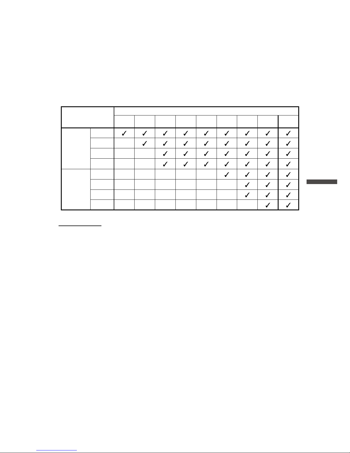
When the recording interval is less than 1 sec, the number of
channels that can be recorded simultaneously varies depending upon
the combination of settings made for 50-60Hz Filter and Recording
Interval.
Recording Intervals
2ms 5ms 10ms 20ms 50ms 100ms 200ms 500ms
1sec or
more
60min
50-60Hz
Filter
OFF
1ch
2ch
3ch
4ch
50-60Hz
Filter
ON
1ch
2ch
3ch
4ch
IMPORTANT
- When you select “Auto” as the measurement range, recording intervals of less than 1
second will not be available to be set. If you wish to set the recording interval to less
than 1 second, the measurement range must be set to other than “Auto”.
- It is not possible to make different recording interval settings for each channel.
[CH1 Settings - CH4 Settings]
The following menus can be set for each channel.
[Meas. Range : ±300mV / ±1.5V / ±6V / ±24V / Auto*]
Select the desired measurement range.
* Auto is available only when the detailed settings is set to ON.
[Scale Conv. : ON / OFF]
Select whether or not to use scale conversion.
[Eq.]
Shows the scale conversion equation set in “MCR for Windows” (see
p.50). This equation is applied in the measurement displayed in the LCD,
trend graph displayed in the LCD, and recorded data graph viewed on a
PC.
Page 36
34
[Unit]
Shows the measurement unit set in “MCR for Windows” (see p.50). This
unit is used in LCD (measurement display and trend graph) as well as in
Graph (downloaded recorded data).
[Warn Montr : OFF / Lower / Upper / Up&Low]
OFF : Does not monitor for warnings.
Lower : Monitors voltage for the set lower limit.
Upper : Monitors voltage for the set upper limit.
Up&Low : Monitors voltage for the set upper and lower limits.
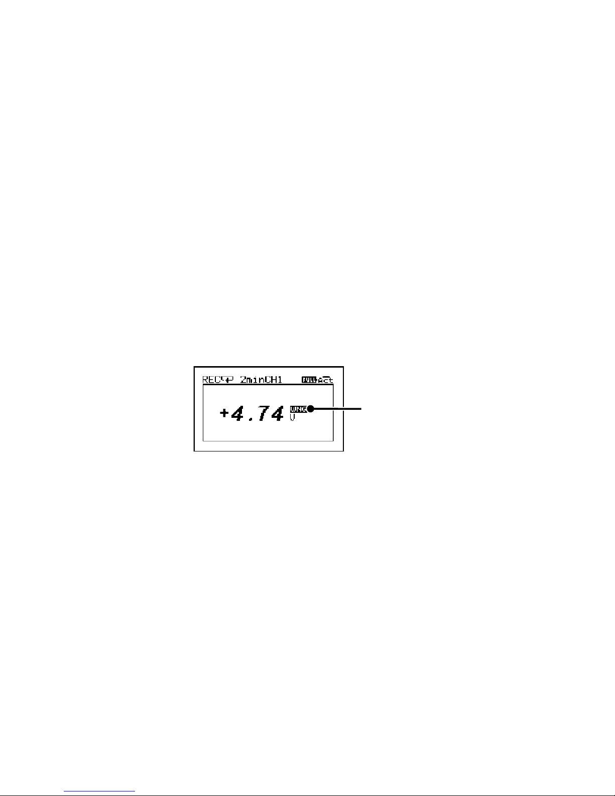
About the Warning Monitoring Function
When the set upper or lower limit is exceeded for the set length of time
necessary to be judged as a warning, the MCR-4V will display a warning
sign next to the measurement value on the LCD.
WARNING
[Uppr Limit] / [Lwr Limit]
Specify the criteria for judging a warning : upper limit and lower limit.
This can be set for each channel.
[Judge Time]
Specify the judgement time (time necessary for the measurement to be
judged as a warning). When this time is set to 0 (zero), a measurement
will be judged as a warning at the moment it exceeds the set upper or
lower limit.
[Preheat : OFF / User-Specied Time]
Select whether or not to use the preheat function. When using the preheat
function, make settings for the length of time to send current to the
sensor.
About the Preheat Function
Preheat is a function which allows the data logger to control power to the
connected sensor. It transmits a preheat signal that is synchronized with
Page 37

35
About Menus
the recording interval to turn sensors ON before and OFF after measuring
and recording.
Other than the sensor ON/OFF function, preheat can also be used to
control transient-load battery, lights, heater, and transient signals.
Preheat Time
When using the preheat function, this stands for the length of time to
send current to the sensor before measurement and recording is set to
occur. When setting the preheat time that is equivalent to or longer than
the recording interval, current will be supplied to the sensor at all times.
Preheat Time
ON ONOFF OFF OFF
Preheat Time
Measure and Record Measure and Record
Current to Sensor
IMPORTANT
- When using the preheat function, the LCD display will be refreshed based on the
recording interval set in the device. (this is due to the fact that the sensor is taking no
measurements other than at the set recording interval)
- The necessary preheat time varies depending upon the sensor to be used; please
check the specications of the sensor before making settings for the preheat time.
Connection Example
MCR-4V
ex) CH1
Preheat
Terminal
Sensor
Power
Sensor
Output
Input
Terminal
Page 38
36
[Rec.Stop Trigger]
To enable the Recording Stop Trigger, set [Function] to ON and carry out
the following settings.
[Channel]
Select the channel which will be used for the trigger.
[Slope : Rising / Falling]
When the input signal reaches the set voltage level, select whether to
trigger on the rising slope or falling slope of the signal.
[Voltage]
Set the voltage level as the trigger condition.
[Stop in]
Set the delay to stop recording after the trigger condition has been
reached.
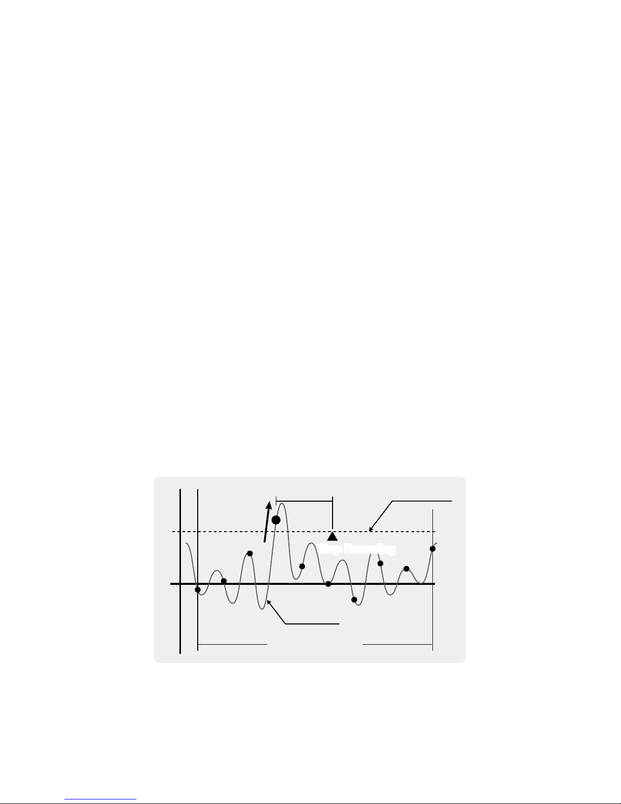
About the Recording Stop Trigger Function
This is a function to determine when to stop recording. The MCR-4V will
stop recording after the set trigger condition has been reached and the
set delay time has elapsed.
Slope
Rising
User Specied Delay
Recording Interval
Stop Recording
Trigger Level
Input Signal
Stop Recording
* The necessary conditions for the stop trigger are only detected at the points of input
signal measurement; at the point of recording, even if the conditions are met, they
will not be detected.
Page 39
37
About Menus
[Save/Restore Sett.]
By selecting [Save Settings], it is possible to save up to 4 types of
recording settings. All setting items in the [Record Settings] menu can be
saved and re-used, allowing you to save steps to repeat making the same
settings each time.
To use the saved recording settings (No.1 to 4), open them by selecting
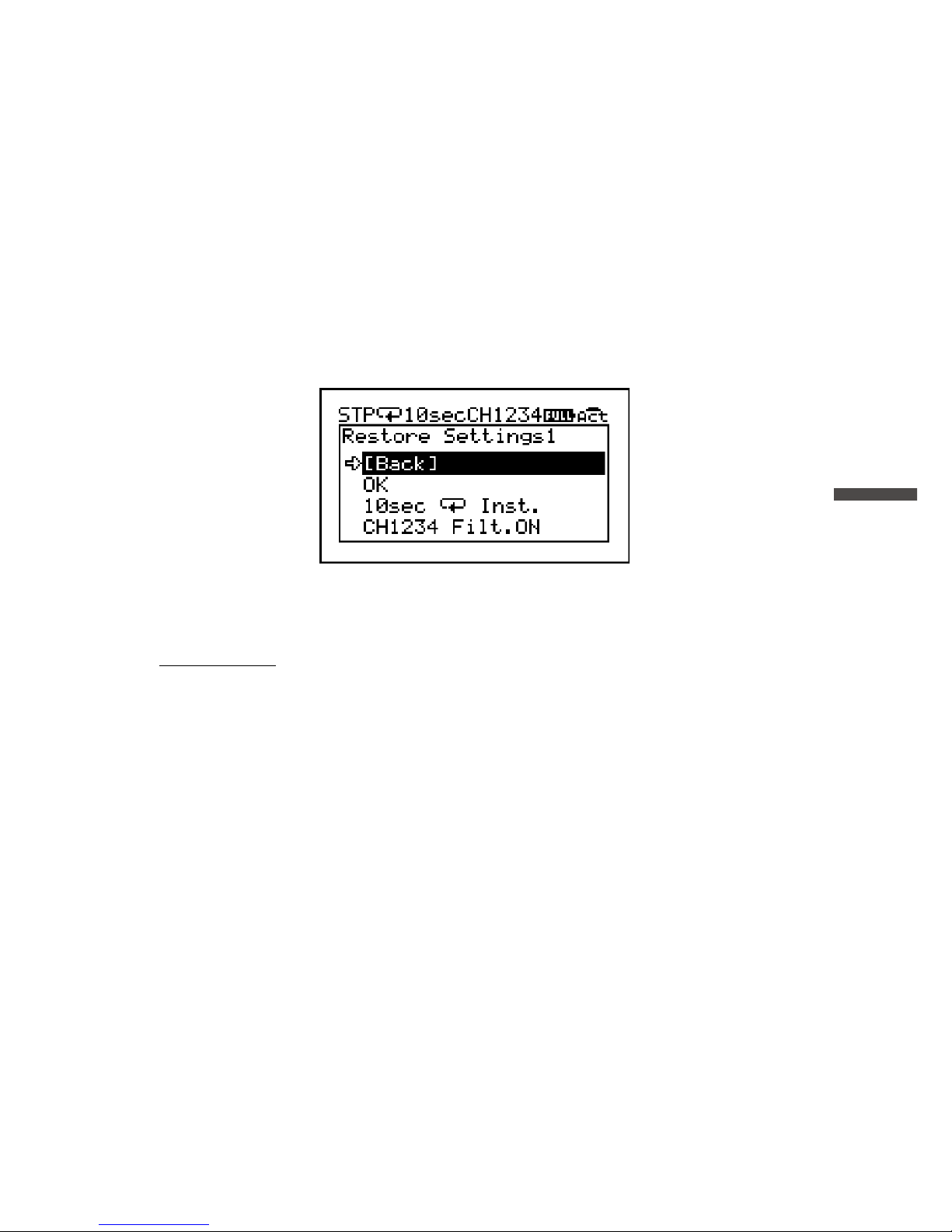
[Restore Settings (No.1 to 4)]. [Restore Settings] screen will show a part of
the record settings as below.
* The bottom line of the screen alternately displays the recording channel(s) and
50-60Hz lter setting, then the measurement range. If no operations are performed
for a while, the alternating display will stop.
IMPORTANT
- Only settings that have been saved from [Save Settings No.1 to 4] are available for
restoring.
- While a recording is in progress, recording settings can only be saved, but not restored.
- ALL saved settings will be deleted by executing [Return to Default] from the [Operation
Settings] menu. It is not possible to delete each saved setting individually.
Page 40

38
[Data List] Menu Items (when recording stopped)
[Display Graph]
From the displayed list, select data you wish to view in a graph and tap
<ENTER>.
[Export Selctd Data]
From the displayed list, select data to export to the SD memory card and
tap <ENTER>.
IMPORTANT
- Memory cards are not included. Please purchase separately.
- Multiple data les cannot be selected for exporting.
[Export All Data]
Select [OK] to export all data to the SD memory card.
IMPORTANT
- Before inserting an SD memory card into the device, make sure to switch off write
protection on the memory card.
- Exporting data to the memory card will not erase it from the device’s internal memory.
Delete recorded data in the device as necessary.
Supported Memory Cards
SD Memory Cards
SDHC Memory Cards
IMPORTANT
- SDXC memory cards cannot be used.
- It is possible to run a quick test to see if your memory card works in MCR-4V. See p.44
for details.
Page 41
39
About Menus
[Delete Selctd Data]
While “Processing” is displayed on the LCD, do not perform any
other operations. This process may take a long time to
complete.
Select the data you wish to delete from the displayed list, and tap
<ENTER>.
* If no operations are performed for a while on the data list screen, you’ll return to the
previous screen.
* Deleting only a few (1-3) data readings from a list which contains a small number of
readings may have no effect on memory usage. (see p.45 for how to check memory
capacity)
[Delete All Data]
[On This Device Only]:
Select [OK] to delete all recorded data on the device currently in
use.
[On All Devices]:
Select [OK] to delete all recorded data on the Master and all
connected Slave units all together.
* If you try to perform this operation on a Slave unit, the [Delete All Data] menu will
only show the [On This Device Only] option.
How to Read Recorded Data Graph
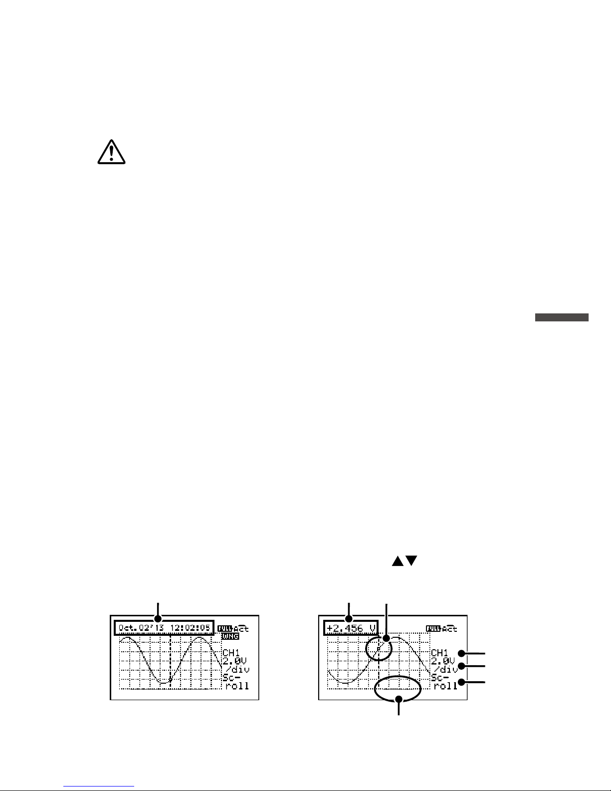
The graph can be scrolled on the display by using or control wheel
operation to move to the left or right.
2.
3.
4.
1.
5.
6.
7.
Page 42

40
1. While scrolling, the time of recorded data appears on the top of the
screen.
2. The time of recorded data will switch to the measurement, a few
seconds after you stop scrolling.
3. The measurement shown in 2 is the value of the point located at the
center of the graph.
4. The bar on the bottom of the graph shows the portion of the data in the
view window.
Tapping <ENTER> allows you to change 5, 6 and 7.
5. Recording Channel
Select the desired channel to view a graph. If the displayed channel has
not been used for recording, you will see the “No Record” message.
6. Vertical Axis Scale
Set scaling value for Y-axis divisional boxes.
EX) “2.0V/div” shows that each vertical division represents 2.0 V.
7. Skimming Level (Horizontal Axis Scale)
Set skimming level for X-axis divisional boxes.
Skim×1 : The space between dots (data points on graph) is same as the
recording interval value
Skim×n : The space between dots (data points on graph) is “n” times
the recording interval value
The horizontal axis of
the graph display shows
a total of 100 dots.
(10 dots per box) × 10 boxes = 100 dots
There are ten data
points (dots) in each
divisional box.
Enlarged View
EX1) When recording interval is 10 ms and skimming level is “×1”:
Each horizontal divisional box represents 100 ms (10 ms × 1 × 10
dots) with the total screen width showing 1 sec (100 ms × 10 boxes)
of recorded data.
EX2) When recording interval is 10 ms and skimming level is “×2”:
Each horizontal divisional box represents 200 ms (10 ms × 2 × 10
dots) with the total screen width showing 2 sec (200 ms × 10 boxes)
of recorded data.
Page 43
41
About Menus
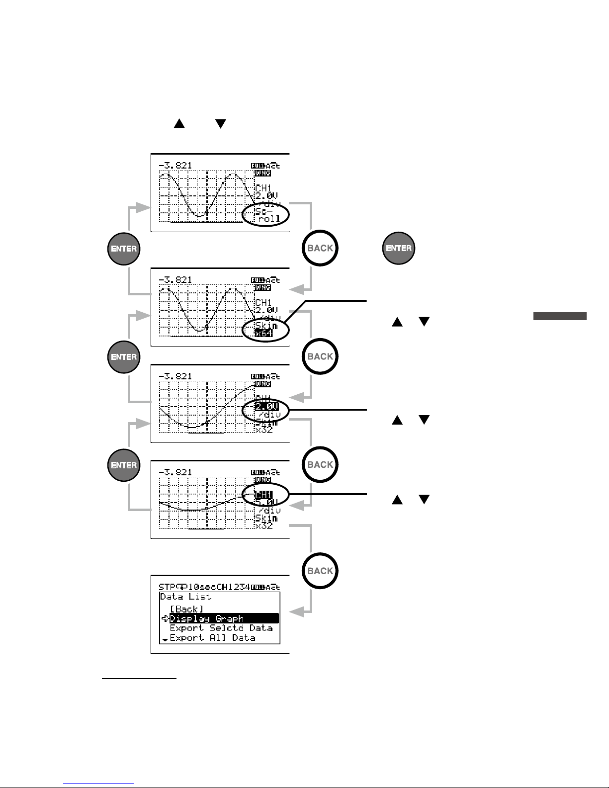
Use <ENTER> and <BACK> to move to the target item, then change
the value with
and .
Skimming Level (Horizontal
Axis Scale)
Use
or to change.
Scroll Screen
Change Screen
Menu Screen
or
Vertical Axis Scale
Use
or to change.
Recording Channel
Use
or to change.
IMPORTANT
When changing settings as above, if no operations are performed or a change is not
conrmed with <ENTER>, the change will automatically be applied and the graph will
return to the “Scroll” mode.
Page 44
42
[Data List] Menu Items (during endless recording)
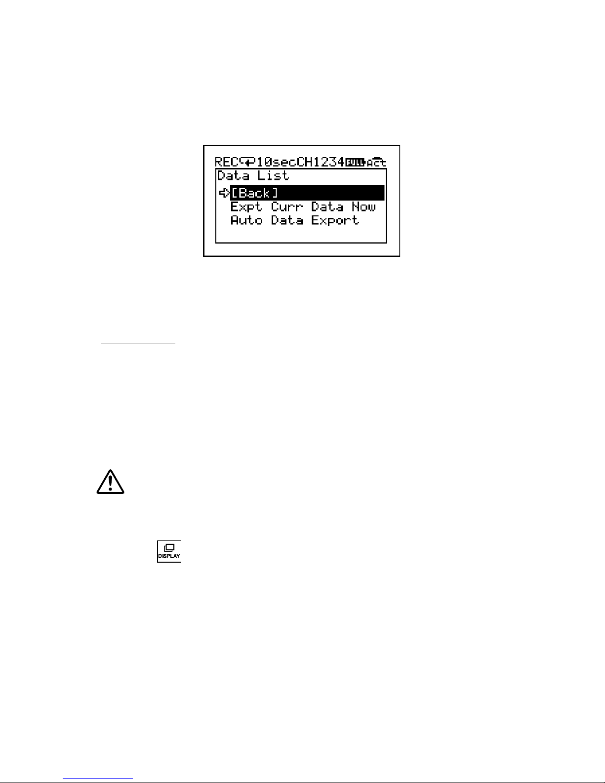
[Expt Curr Data Now]
Use this to immediately export the data currently being recorded to the
SD memory card.
IMPORTANT
Memory cards are not included. Please purchase separately.
[Auto Data Export]
To prevent data loss in Endless mode, this menu will automatically export
the data to be overwritten to the SD memory card.
* When the internal memory capacity becomes full in Endless mode, the most recent
data will be overwritten and recording will continue.
Make sure to use a formatted blank SD card, or carry out a
“Quick Format” (see p.44).
* During the [Auto Data Export] process, other operations cannot be performed except
for switching the LCD display between [Menu] - [Measurements] - [Trend Graph] by
pressing .
Page 45
43
About Menus
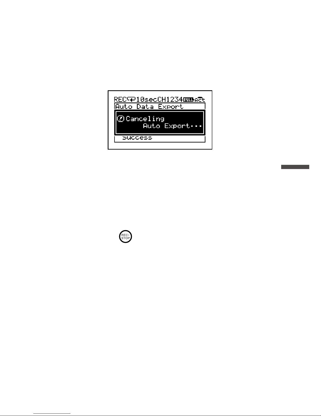
Canceling [Auto Data Export]
If you wish to cancel the auto data export process, select [Back] and tap
<ENTER>.
The displayed message will be cleared when the process is terminated.
Restrictions on [Auto Data Export]
- The exporting process will be terminated when the SD card is removed.
- The process will be terminated when an SD card write error occurs.
- The process will be terminated when recording is stopped.
- USB communication cannot be used until the process has been
completed.
- During the process,
is deactivated and cannot be used to stop
recording.
Page 46

44
[Memory Card] Menu Items
[Quick Format]
Select [OK] to format your SD memory card for use in the MCR-4V.
IMPORTANT
- This process will erase all recorded data from the SD memory card. It is recommended
to make backups of recorded data to a PC before formatting the memory card.
- It is not possible to erase individual data readings from the SD memory card.
- Do not turn off the power while the device and SD memory card are in communication.
If the device is running on batteries, make sure the batteries have power and are
installed correctly. If power is supplied by a PC over the USB bus, avoid power supply
disruption due to cable disconnection or power-saving settings on the PC.
[Memory Card Test]
Select [OK] to check if your SD memory card can be used with the
MCR-4V. Not all commercially available SD memory cards can be used. It
is recommended to do this test before using.
IMPORTANT
If the memory card you wish to use passes the test but has problems when using, carry
out “Quick Format”.
Page 47

45
About Menus
[Operation Settings] Menu Items
[Set Contrast]
Adjust the LCD contrast with and . Tap <ENTER> to conrm the
contrast.
[Check Memory]
You can check the memory usage (% of capacity) and the number of
recorded data.
[Set Clock]
1. Tapping will change the selection item of the display in the order of
month, day, year, hour, minute, and second. By tapping <ENTER>, the
value for that item will ash.
2. While ashing, use
to select the desired value and tap <ENTER> to
conrm.
3. Move to the next or previous setting item with
or .
* By tapping <BACK> while the selected item is ashing, the operation will be
canceled and ashing will stop.
[Time Zone] and [DST]
Set time zone and daylight savings time (DST) according to the region in
which the MCR-4V will be used.
IMPORTANT
- It is not possible to set the clock while recording is in progress.
- Please make sure that the date and time settings in the MCR-4V are correct, if they are
not, the recording start time and recording time of downloaded data will be incorrect.
- Clock settings (including time zone and DST) for the MCR-4V can also be made from
your computer by using the supplied software “MCR for Windows”. When making
settings via “MCR for Windows”, it is not necessary to carry out operations from the
MCR-4V.
[Beep]
This allows you to turn off the operation conrmation beeping sound.
* The “OFF Click” option will turn off the conrmation sound for touch panel operation
only.
Page 48
46
[Key Lock]
This function automatically disables the use of the touch panel if no
operations occur during a set period of time. It helps prevent handling
mistakes.
Use
to specify the amount of time before the lock sets (in 1-sec
units).
* If you wish to turn ON the key lock immediately, press and hold on the touch
panel. The lock can be released by pressing and holding again.
[Return to Default]
By clicking [OK], the device will be initialized by returning it to the factory
default settings.
This will delete all data stored in the device and initialize the
settings. Please be careful when initializing a device as it is not
possible, after initialization, to retrieve previous settings info or
recover deleted or corrupted data.
Do not turn off the power of the MCR-4V during initialization.
Termination of the initialization process may cause damage or
malfunction to the device.
Page 49
47
Using a PC with MCR-4V
Using a PC with MCR-4V
By using the supplied software, it is possible to make Device Settings
and Recording Settings from a computer, as well as download recorded
data from the MCR-4V to your computer for graph view and data
analysis.
Installing the Supplied Software
The software installation procedure is as follows:
1.
Start Windows and login using a User Account with Administrator
(Computer Administration) rights.
2.
Place the CD-ROM into your CD or DVD drive.
3.
The [Install Program] window will appear.
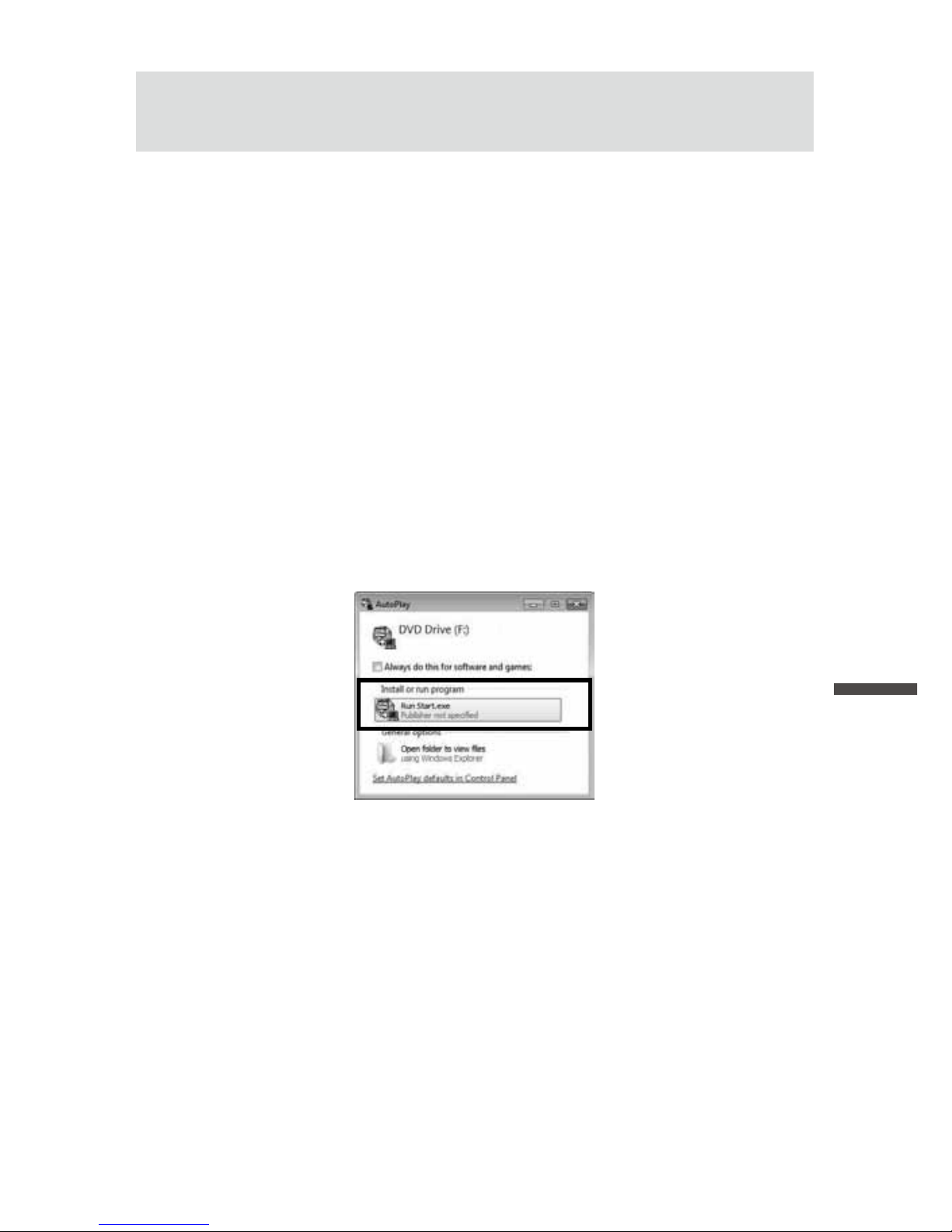
If the [Auto Play] window appears:
Click on [Run start.exe].
If the [Install Program] window does not appear automatically:
Double click on the [start.exe] icon in the CD/DVD drive.
Page 50
48
4.
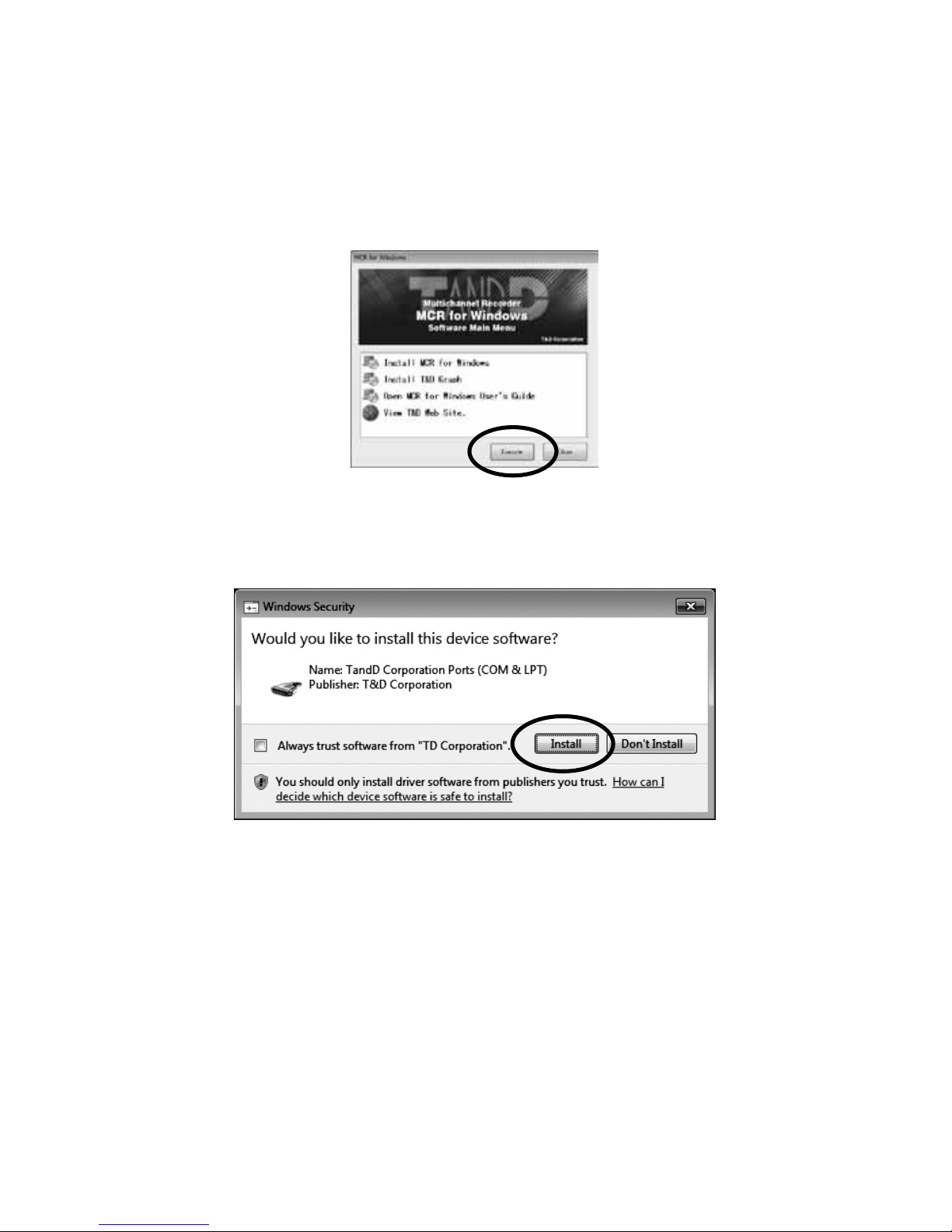
Select “Install MCR for Windows” and click [Execute] to start the
installation.
5.
Follow the directions as they appear to complete the installation.
* If a window appears such as the one below during installation, click [Install] or
[Continue Anyway].
After installation, “MCR for Windows” will appear in the Windows Start
Screen or Start Menu.
6.
To view recorded data in a graph or print out, go back to step 4. and
install “T&D Graph”.
* For details about operations please see the “Help” menu in the software.
Page 51
49
Using a PC with MCR-4V
Connecting the Device to a PC
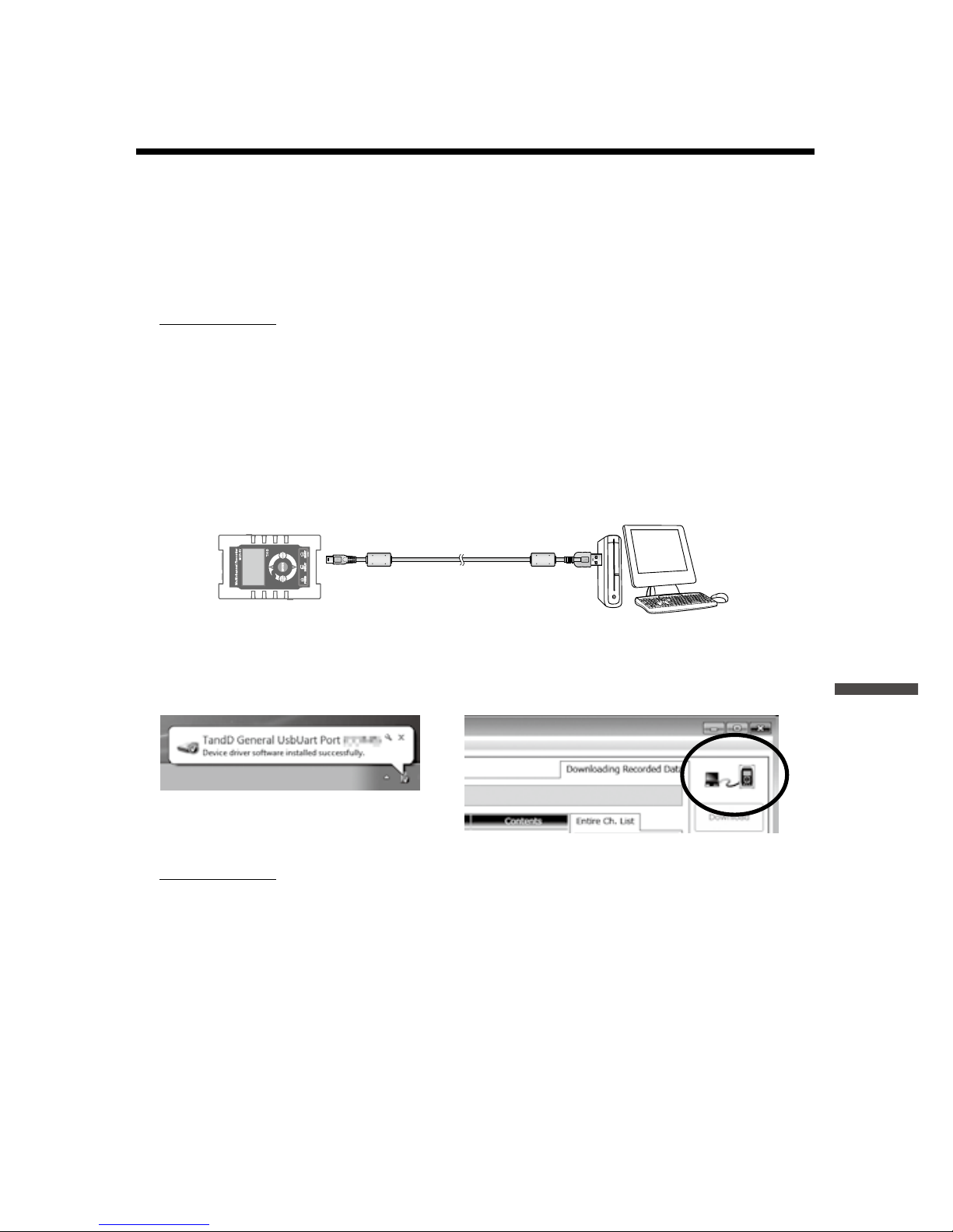
1.
Open “MCR for Windows” from the Start Screen or Start Menu.
2.
Connect the device with the supplied USB cable to your computer.
The USB driver installation will start automatically.
IMPORTANT
- Make sure to install the supplied software “MCR for Windows” before connecting the
MCR-4V to the computer.
- The USB device driver must be installed before trying to carry out USB communication.
After installing the USB device driver, your computer will be able to detect and
recognize any MCR-4V unit that is connected with a USB communication cable.
- When connecting a MCR-4V to a PC, connect only one unit at a time. If you connect
multiple units at the same time, they may not be recognized properly.
- For the installation procedure of the software “MCR for Windows”, see p.47.
USB Communication Cable
(US-15C)
When the USB driver installation completes, on the upper right corner of
the software screen, you will see an icon showing the PC and MCR-4V
connected via USB.
IMPORTANT
If you don't see this icon, the USB driver may not have been installed correctly. Please
see [Help for Unit Recognition Failure] in the Help menu, and check the USB driver.
Page 52

50
Making Settings via PC
The following items are not included on the device menu, and can only
be set or changed from “MCR for Windows” by connecting the device
to a computer via USB.
Channel Name
Create and assign names to each of the channels to be used for
recording. Channel Names are used for display in “T&D Graph”.
1.
Select the [Recording Start Settings] menu in “MCR for Windows”.
2.
Place a check next to the desired channel(s) and enter each channel
name.
3.
Click [Send Settings].
Scale Conversion Equation
1.
Select the [Scale Conversion / Unit Settings] menu.
2.
Place a check next to the desired channel(s).
3.
Set “Scale Conversion” to ON for each channel.
4.
Select either [Convert by using the equation: y=ax+b] or [Convert by
specifying 2 points], and enter a value in each box.
5.
Select the number of signicant digits after scale conversion.
6.
Click [Apply Settings].
Unit Settings
1.
Select the [Scale Conversion / Unit Settings] menu.
2.
Open the “Measurement Unit” tab page, and set [Unit for use in Graph]
for display in “T&D Graph” and [Unit for use in LCD] for measurements
and graph display in LCD.
3.
Click [Apply Settings].
Page 53
51
Using a PC with MCR-4V
Downloading Recorded Data to a PC
Data stored in the internal memory of MCR-4V can be downloaded to a
computer in either of the following two ways:
- Use an SD memory card to export recorded data and transfer to a PC.*
- Use “MCR for Windows” to download by connecting the device to a PC.
* For how to export recorded data to an SD memory card, see p.38.
IMPORTANT
When recording is in progress, there are restrictions on functions related to the SD
memory card.
Download Recorded Data using “MCR for Windows”
By connecting the device to a PC with a USB communication cable, it
is possible to download recorded data to a PC.
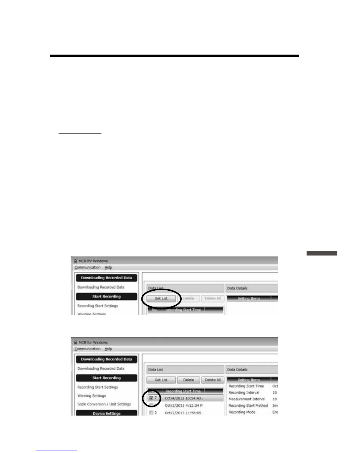
1.
Open “MCR for Windows”.
2.
Connect the device to your computer.
3.
Click [Get List] in the [Downloading Recorded Data] window.
4.
Check the desired data in the list.
Page 54
52
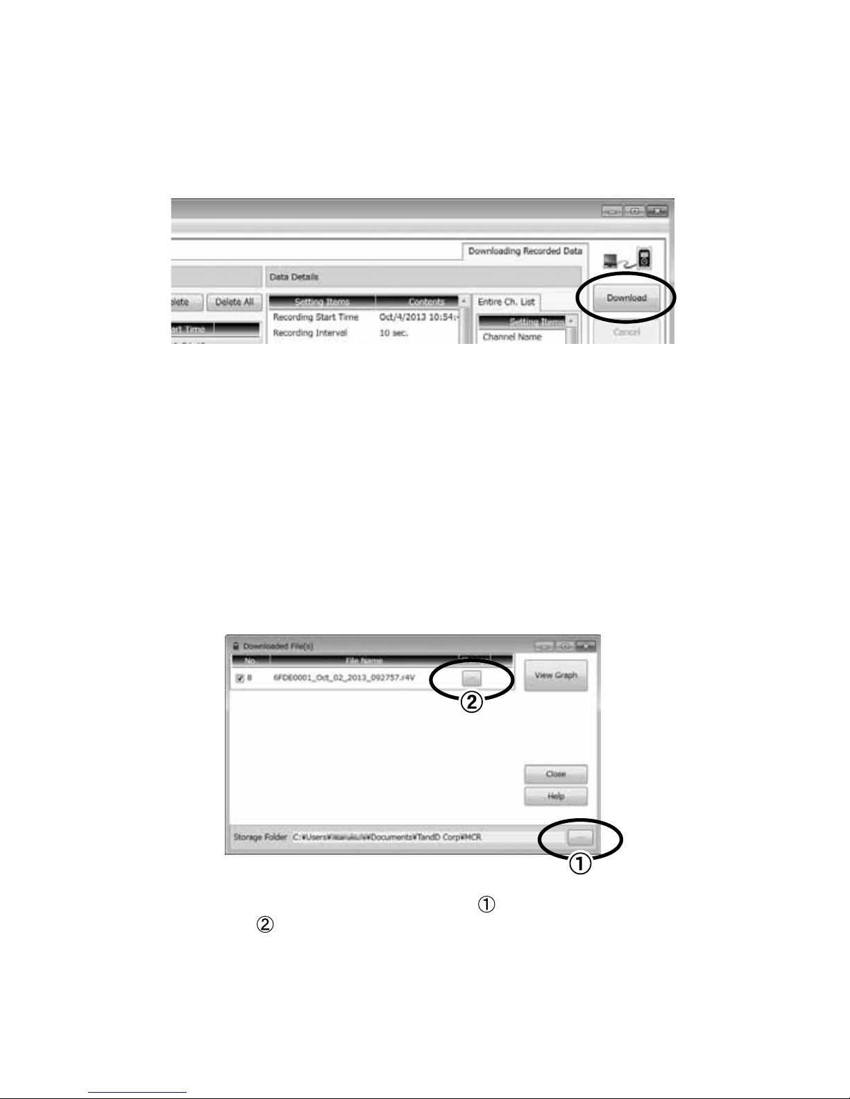
5.
Click [Download].
Recorded Data File
One recorded data le (.r4V) is created for each recording session.
Storage Location of Recorded Data and File Name
The default setting is as follows.
Storage Folder:
C:\Users\username\Documents(or My Documents)\TandD Corp\MCR
File Name:
Serial number_rec.month_rec.day_rec.year_rec.time (hhmmss).r4V
To change the default storage folder, click and specify the desired
folder. Button
allows you to specify the desired le name as well as its
location.
Page 55

53
Using a PC with MCR-4V
Download Recorded Data from all Connected MCR-4V
Units
1.
Connect the Master unit to your computer via USB.
2.
Get a data list for the Master. (see p.51)
3.
Click [Search for Slave] to get data lists for the connected Slave units.
4.
Place a check next to the target data.
* It is possible to select data from both the Master and Slave unit(s) for simultaneous
download.
5.
Click [Download].
* If it takes too long to download data recorded from Slave units, it is also possible to
directly connect a Slave to the PC via USB and download individually. (You can
switch the USB cable from the Master to connect a Slave.)
IMPORTANT
Do not disconnect the USB cable during communication between a device and the PC.
Page 56
54
Analyzing Recorded Data
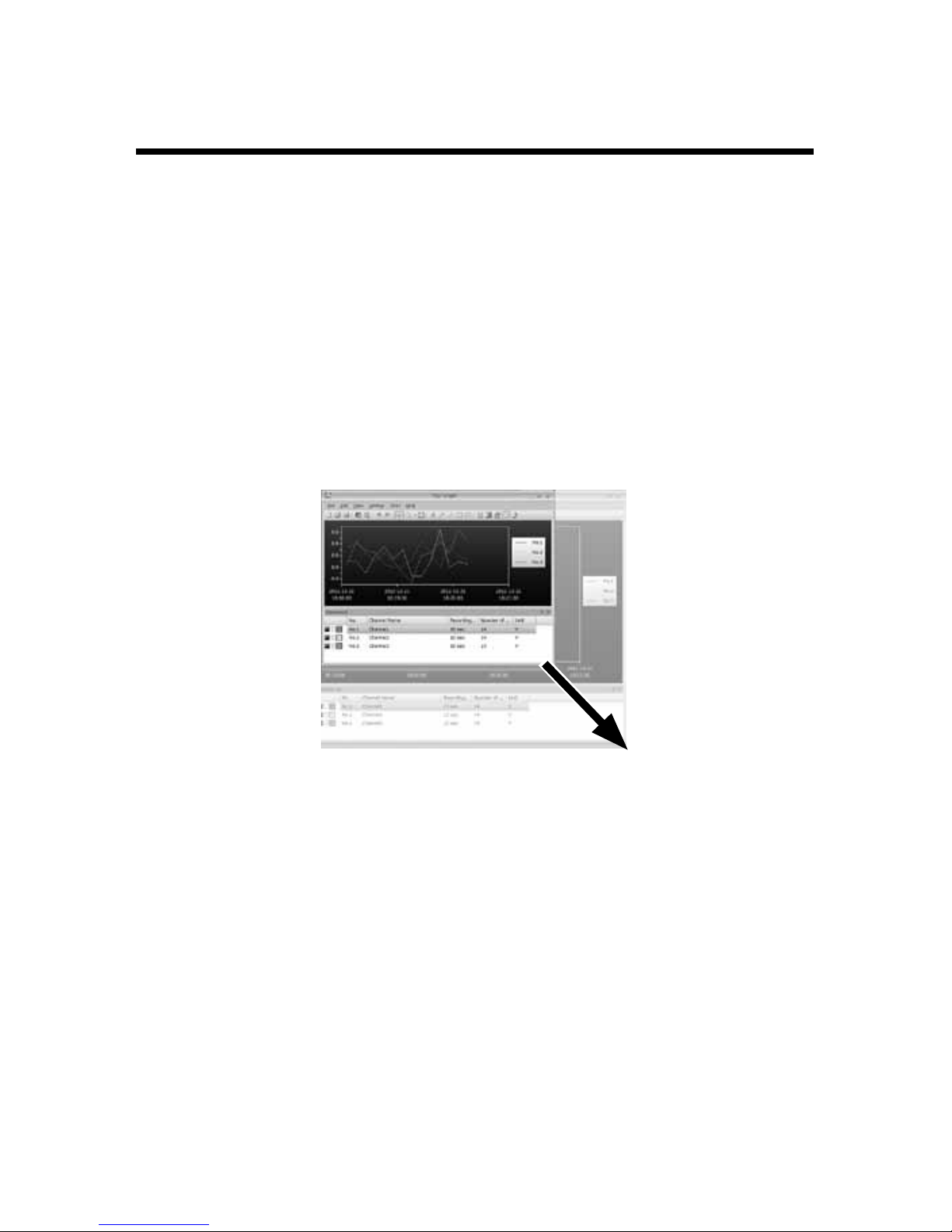
Open Recorded Data
In the storage folder for the downloaded recorded data on your PC
(p.48), double click on the desired recorded data le. “T&D Graph” will
be opened and a graph displayed.
Print Graphs
1.
Open recorded data from “T&D Graph”.
2.
Make any desired adjustments to the window size and aspect ratio to
be reected in the printed graph.
3.
In the [File] menu, select [Print Graph] to view the preview image of the
printed page. If necessary, go back to step
2
and change the aspect
ratio again.
4.
To start printing, select [Print].
“T&D Graph” also enables you to:
- Insert memos, comments, and shapes on the graph
- Merge and lter recorded data
- Copy graphs
- Display data as a list
- Export the graph as text data (in CSV format)
* Refer to Help in “T&D Graph” for details about operations and procedures.
Page 57

55
Other
Other
Troubleshooting
Q1.
The computer does not seem to recognize the MCR-4V,
why not?
A1.
Please check the following:
Check the MCR-4V
Check the USB connection between the computer and the MCR-4V.
Check the Computer
• Make sure that the software has been installed properly and is
working.
• The USB driver installation may not have been installed correctly.
Please see [Help for Unit Recognition Failure] in the Help menu,
and check the USB driver.
• Connect a different USB device (mouse, digital camera, etc...)
other than the MCR-4V to your computer and see if it operates
properly.
• If your computer has more than one USB port, try connecting the
USB cable to a different port.
• If you have access to another computer, try seeing if communication works with the other computer.
If after checking and trying the above there is no improvement
please contact the distributor where the product was purchased.
Q2.
The rst reading of recorded data is invalid data, why?
A2.
One of two scenarios is possible:
• When recording average values, the rst recorded value is invalid
because an average cannot be calculated.
• When the Preheat function has been set to ON (recording method:
Page 58

56
instantaneous values only) and the preheat time is set to longer
than the waiting time before recording start, the rst data reading
will be invalid because preheating has not been completed.
Q3.
Is it possible to change the batteries while the unit is in
operation?
A3.
If the unit is connected to an AC adaptor or some other external
power source, it is possible to change the batteries. If only
batteries are being used as the power source, it is necessary to
stop recording before changing the batteries.
Q4.
Is it possible to adjust or alter recorded data that has
been downloaded by the MCR-4V?
A4.
In order to maintain the integrity and trustworthiness of the
recorded data, the software has been designed to not allow
modications to be carried out on actual recorded data.
If it is necessary to edit recorded data, in “T&D Graph” save the
data to text le and use a common spreadsheet software such
as Excel to edit the text le data.
Q5.
I get a “Write Error” when I try to export recorded data to
an SD memory card, what should I do?
A5.
Please check the following:
• Make sure the write protection switch on the SD memory card is
unlocked.
• Check if your SD memory card is supported by the MCR-4V. (See
p.38)
• Perform a “Memory Card Test”. (See p.44)
• Perform a “Quick Format” for your SD card. (See p.44)
If after checking and trying the above you still get an error
message, please contact the distributor where the product was
purchased.
Page 59
57
Other
Q6.
The software “MCR for Windows” does not start, why
not?
A6.
Please check the following:
• The software may not have been installed correctly. Try reinstalling
“MCR for Windows”.
• Check to see if the software was installed with Administrator rights.
(For Windows 7 or earlier:)
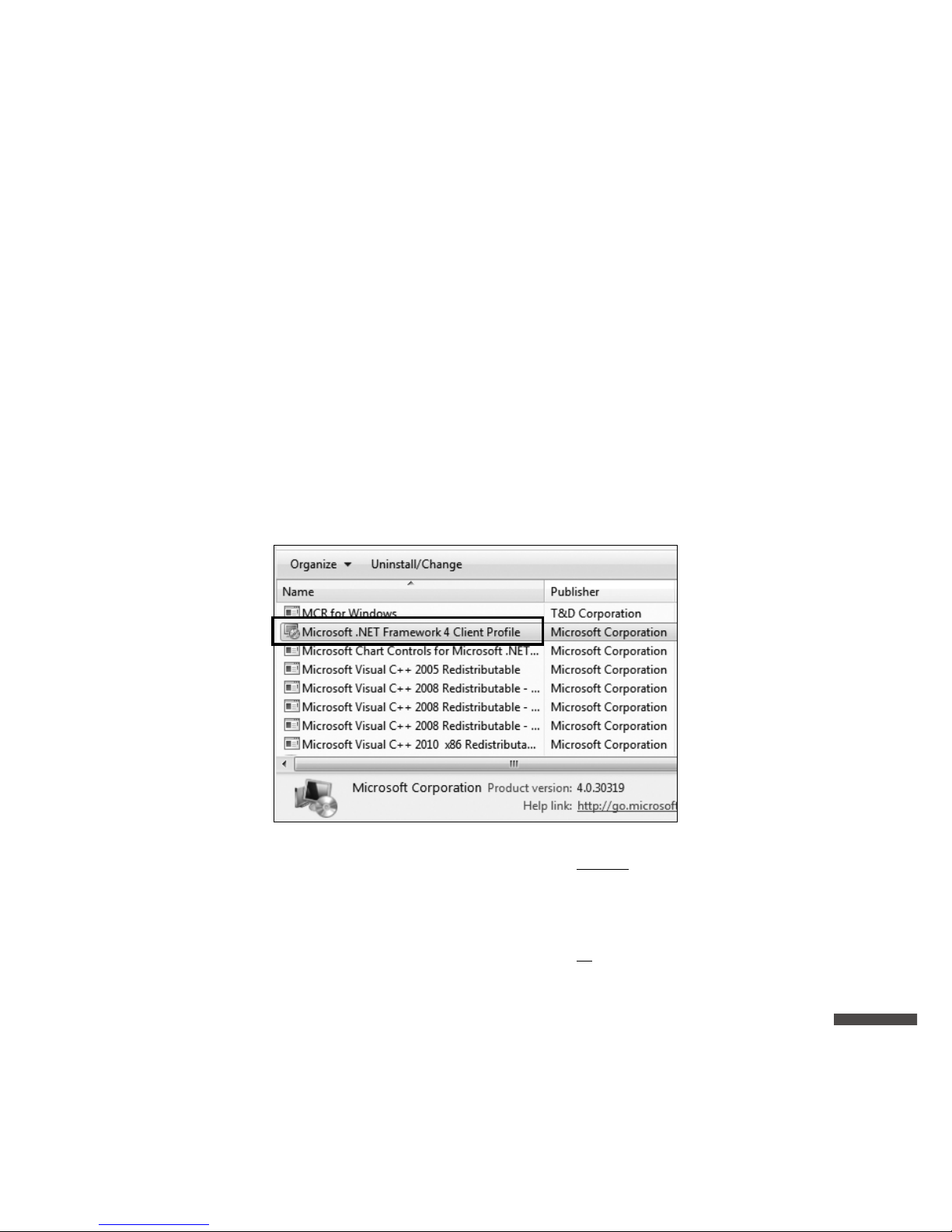
• The .NET Framework 4 Client Prole may not have been installed
correctly. Follow the steps below to see if the .NET Framework 4
Client Prole has been installed correctly.
In the Control Panel, open [Program and Features] or [Uninstall a
Program].
When the .Net Framework 4 Client Prole is not in the list above:
Try reinstalling “MCR for Windows”. The .Net Framework 4 Client
Prole will be automatically installed with “MCR for Windows”.
When the .Net Framework 4 Client Prole is in the list above:
Follow the steps below to repair the .Net Framework 4 Client Prole.
1. Select Microsoft .NET Framework 4 Client Prole and click
[Uninstall or Change].
Page 60
58
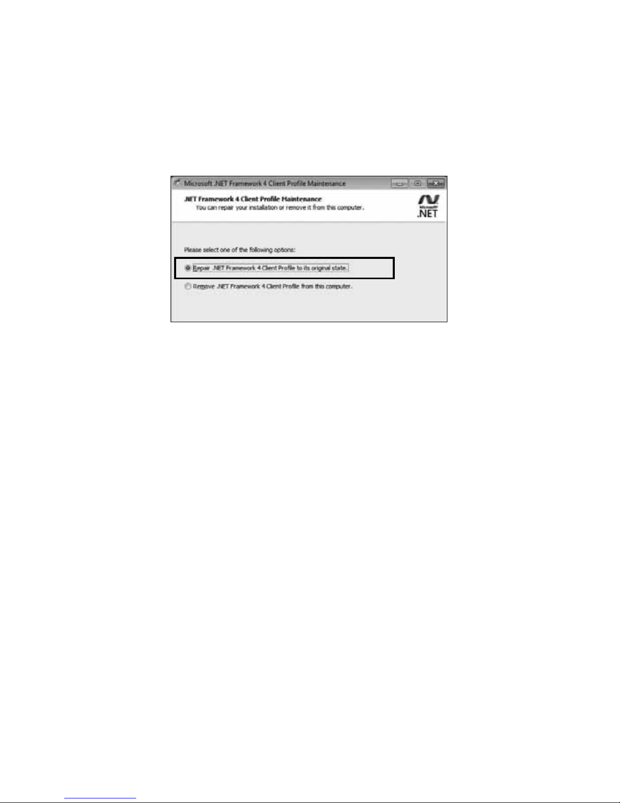
2. In the maintenance box, select “Repair .NET Framework 4 Client
Prole to its original state” and then click [Next]. Click [Finish] when
prompt.
If after checking and trying the above there is no improvement
please contact the distributor where the product was purchased.
Page 61

59
Other
Page 62
60
Specications
MCR-4V
Measurement
Channels
Voltage 4ch
Input Method Scanning Method, Differential Input, Each Channel Isolated
Input Impedance Approx. 1.1 MΩ
Input Frequency DC-100 Hz
Measurement
Range
±300 mV, ±1.5 V, ±6 V, ±24 V, Auto (*1)
Absolute Maximum Input Voltage: ±50 V
Accuracy When the 50-60 Hz lter is ON, varies with the Measurement
Range as follows:
±300 mV : ±(0.3 % + 0.06 mV)
±1.5 V : ±(0.3 % + 0.3 mV)
±6 V : ±(0.3 % + 0.6 mV)
±24 V : ±(0.3 % + 2.4 mV)
Auto : According to the range in use
Measurement
Resolution
50-60 Hz Filter ON : 0.01 mV
50-60 Hz Filter OFF : 0.1 mV
Preheat Function Allowable Voltage Range : 3 to 24 V (external power supply)
Allowable Maximum Current : 1.0 A
Recording
Method
Instantaneous, Average, or Ave. Fine
Recording
Interval
2, 5, 10, 20, 50, 100, 200, 500 ms.
1, 2, 5, 10, 15, 20, 30 sec.
1, 2, 5, 10, 15, 20, 30, 60 min.
(The minimum interval will depend on the number of
channels, measurement range, and 50-60 Hz lter setting.)
Logging Capacity
(*2)
When recording 1 channel : up to 480,000 readings/ch
When recording 2 channels : up to 240,000 readings/ch
When recording 3 channels : up to 160,000 readings/ch
When recording 4 channels : up to 120,000 readings/ch
Recording Mode Endless (Overwrite oldest data in the current recording
session when capacity is full) or One Time (Stop recording
when capacity is full)
Recording Start
Method
Immediate Start or Programmed Start (by individual logger or
by group)
Page 63
61
Other
Recording Stop
Trigger
ON or OFF
Group Recording Up to 4 units (16 channels) can be recorded simultaneously.
Communication
Interfaces
USB Communication
Communication
Time
Download Times for Full Data via USB
- While recording (at recording interval of 2 ms.) : Approx. 3
minutes 30 seconds
- With recording stopped: Approx. 1 minute 30 seconds
- From a slave unit: Approx. 4 minutes 30 seconds
External Memory SD Memory Card, SDHC Memory Card (*3)
(For Manual or Automatic Data Export)
Power AA Alkaline Battery x 2 (AA Ni-MH batteries may also be
used), AC Adaptor (AD-05A2 or AD-05C2), USB Power (5V
250mA)
Battery Life (*4) Approx. 4.5 to 150 days (with AA alkaline batteries)
Input Terminal /
Preheat Terminal
Screwless Terminals
<Compatible Wires>
Single Wire : Ø0.32 to Ø0.65 mm (AWG 28 - 22)
Twisted Wire : 0.08 to 0.32 mm2 (AWG 28 - 22), Ø0.12 mm or
more in diameter
Stripping Length : 9 to 10 mm
Isolation CH1, CH2, CH3, CH4, USB, and Preheat are isolated. (Battery
terminals are not isolated from the CH1-CH4 input terminals.)
CH1-CH4 Maximum Applied Voltage : ±50 V
Electrical Isolation Resistance : 50 MΩ or more (DC±250 V)
Dimensions H 120 mm x W 75 mm x D 32 mm
Weight Approx. 190 g (including batteries)
Operating
Environment
Temperature: 0 to 50 °C
Humidity: 90 %RH or less (no condensation)
*1: When “Auto” is selected, measurement range will be automatically changed according
to the voltage being measured.
*2: If the logging capacity is not lled at the end of one recording session, the logger can
record up to 30 times.
*3: Please check the T&D Website for information on memory cards whose operation has
been conrmed.
*4: Battery life varies depending upon the measurement interval and 50-60 Hz lter
setting. All estimates are based on operations carried out with a new battery and are in
no way a guarantee of actual battery life.
Page 64
62
Software (MCR for Windows)
Compatible OS
(*5)
Microsoft Windows 10 32 / 64 bit
Microsoft Windows 8 32 / 64 bit
Microsoft Windows 7 32 / 64 bit
Microsoft Windows Vista 32 bit (SP1 or later)
Display
Languages (*6)
English
Other The .NET Framework 4 Client Prole is required.
*5: For installation, it is necessary to have Administrator (Computer Administrator) rights.
*6: We recommend using an operating system in the same language as the display
language. Operation in different languages is not guaranteed.
The specications listed above are subject to change without notice.
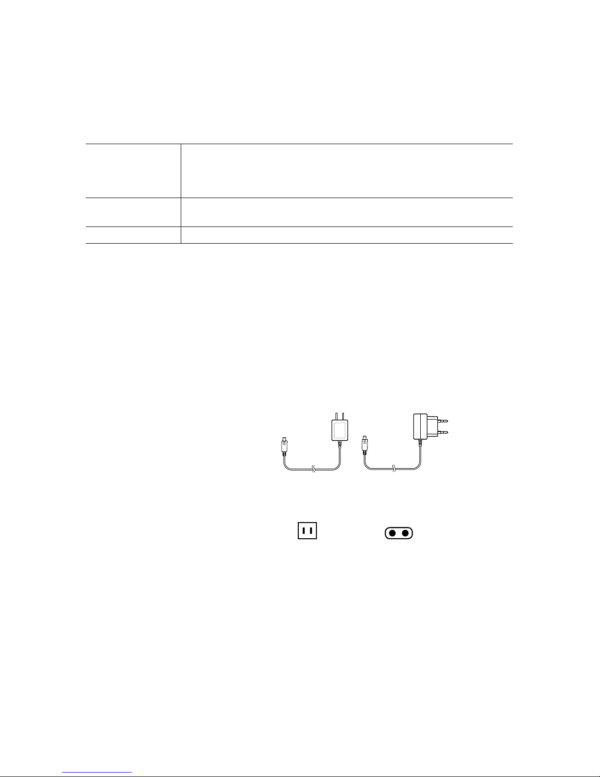
Option
AC Adaptor AD-05A2 / AD-05C2
USB Mini-B Type
Input :
AC100 to 240V
Output : DC5V,1A
Frequency : 50/60Hz
Cable Length : 1.5m
AD-05A2 AD-05C2
Plug Type
Page 65

Page 66

Page 67
Product Support
For support, please contact the distributor from which you
purchased the product.
A list of distributors can be found at:
http://www.tandd.com/about_tandd/contactus/
Product Information
Product information can be found at:
http://www.tandd.com/product/
Multichannel Voltage Recorder MCR-4V
User's Manual
T&D CORPORATION
817-1 Shimadachi, Matsumoto, Nagano 390-0852, Japan
Website : http://www.tandd.com/
FAX : +81-263-40-3152 E-mail : [email protected]
Page 68

 Loading...