

Page 1

Universal Switch Airspeed Kit
Model: USW-1
The universal switch airspeed kit includes an ASW-1 airspeed switch and
a Universal Switch-SPDT controller. This combination of components allows for
the switching of electrical loads up to 10 amps and up to 30 volts based on
aircraft speed. The airspeed set point is factory calibrated to 100 knots,
however, it may be field adjusted to switch at any airspeed between 55 and140
knots. The Universal Switch-SPDT controller provides both a normally open and
a normally closed contact for controlling any electrical load up to 10 amps. This
allows electrical loads to either be on or off above or below the airspeed set
point. The system works with aircraft power systems from 10-30 volts.
USW-1 is not TSO’d and must only be used in aircraft certified in the
Experimental category.
USW-1 must be installed using the current aircraft standards and
practices. Refer to AC 43.13-2A/1B. The installer/builder is solely responsible
for determining the suitability of the installation and use of this product.
1
Page 2

Installation instructions:
1) Connect the wiring harness from the Universal Switch-SPDT controller as
shown in the wiring diagram.
a. Connect aircraft power and ground to the white/red and black wires.
b. Connect the airspeed switch to the white/black and black wires.
c. Connect the electrical load to be controlled to the OUTPUT terminals
using the Common, Normal-open, Normal-closed wires. Up to 10 amps
of load current may be switched. (note: these terminals are isolated from
the input terminals and may be used to switch the power or the ground
connections to the electrical load)
2) Connect the ASW-1 airspeed switch to the aircraft pitot system and static
system using the ports labeled “p” and “s”. Mount the ASW-1 to the aircraft using
the mounting tabs.
3) Mount the Universal Switch-SPDT controller to the aircraft using the
mounting tabs on the enclosure. The control box can be mounted in any
orientation.
PRODUCT OPERATION:
The airspeed switch will command the Universal Switch-SPDT to be conductive
in the normal-closed position when the aircraft is operating below the airspeed
set point. Above the airspeed set-point the Universal Switch will be conductive in
the normal-open position. The airspeed set point is adjustable via the small
screw as indicated in the wiring diagram. Note: This airspeed switch may
additionally be used to control a Safety-Trim controller or an IFC-1 intelligent flap
controller, however they will all share the same airspeed set-point. Ensure this
is satisfactory for all the systems being controlled.
TCW Technologies
2955 Main Road East
Emmaus, PA 18049
610-928-3420
www.tcwtech.com
email: [email protected]
2
Page 3
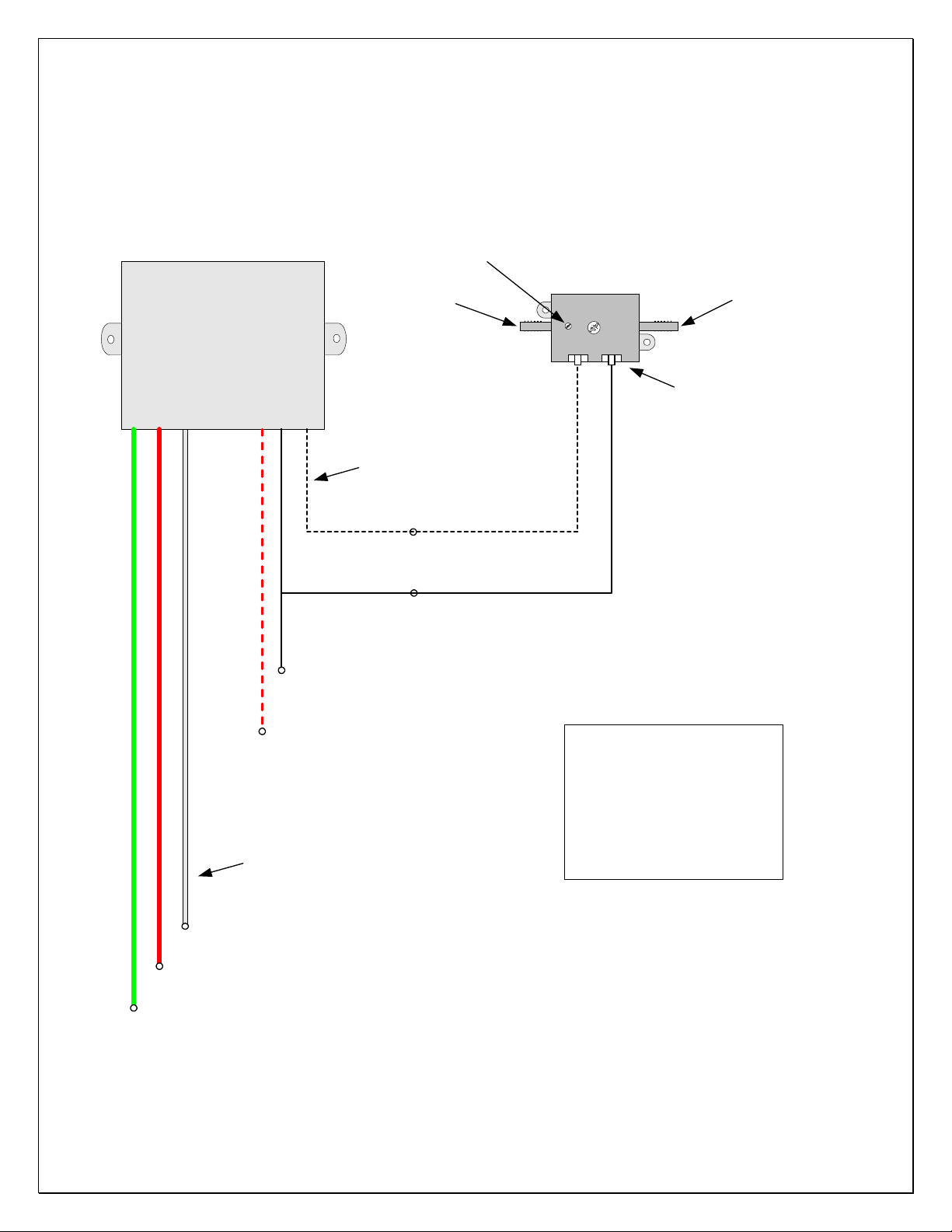
Universal Switch-SPDT
10-30 Volts, 10 amps
InputOutput
USW-1
wiring diagram
Airspeed switch adjustment
Clock-wise to lower airspeed set-point
Static line
All input wires 22 awg
Airspeed switch
white / black stripe
switch ground
black
ASW-1
Pitot line
0.187" Fast-On connectors
Aircraft Ground -
Aircraft Power +
All output wires 16 awg
Aircraft power + wht/red
Aircraft ground - black
Airspeed switch wht/blk
Relay Common white
Normal Closed green
Normal Open red
Common- WHITE
Note: An airframe ground may be used as an alternative
Normal Open- RED
Normal Closed- GREEN
switch ground on the airspeed switch
Note: Adjustment ranges is about from 55 knots to 140
knots. Factory calibrated to 100 knots.
Note: Static connection must be made to Aircraft Static port
3
Page 4

TCW Technologies, LLC.
During the first 24 months from the date of purchase and subject to the conditions hereinafter set forth,
TCW Technologies, LLC. (TCW) will repair or replace to the original user or consumer any portion of
your new product which proves defective due to defective materials or workmanship of TCW. Contact
TCW Technologies for warranty service. TCW shall have and possess the sole right and option to
determine whether to repair or replace defective equipment, parts or components. Damage due to
equipment, environment or conditions beyond the control of TCW Technologies are NOT COVERED BY
THIS WARRANTY.
LABOR, COSTS: TCW shall IN NO EVENT be responsible or liable for the cost of field labor or other
charges incurred by any customer in removing and/or reaffixing any TCW product, part or component
thereof.
THIS WARRANTY WILL NOT APPLY: (a) to defects or malfunctions resulting from failure to properly
install, operate or maintain the unit in accordance with printed instructions provided; (b) to failures
resulting from abuse, accident, or negligence; (c) to normal maintenance services and the parts used in
connection with such service; (d) to units which are not installed in accordance good trade practices; or (e)
to unit used for purposes other than for what it was designed and manufactured.
RETURN OR REPLACED COMPONENTS: any item to be replaced under this Warranty must be
returned to TCW Technologies in Emmaus, PA, or such place as TCW may designate, freight
prepaid.
PRODUCT IMPROVEMENTS: TCW reserves the right to change or improve its products or any
portions thereof without being obligated to provide such a change or improvement for units sold
and /or shipped prior to such change or improvement.
WARRANTY EXCLUSIONS: as to any specific TCW product, after the expiration of the time
period of the warranty applicable thereto as set forth above. THERE WILL BE NO
WARRANTIES, INCLUDING ANY IMPLIED WARRANTIES OR MERCHANTABILITY OR
FITNESS FOR ANY PARTICULAR PURPOSE.
Some states do not allow limitations on how long an implied warranty lasts, so the above
limitation may not apply to you. No warranties or representations at any time made by any
representative of TCW shall vary or expand the provisions hereof.
LIABILITY LIMITATION: IN NO EVENT SHALL TCW OR ITS AFFILIATES BE LIABLE OR
RESPONSIBLE FOR CONSEQUENTIAL, INCIDENTAL OR SPECIAL DAMAGES RESULTING
FROM OR RELATED IN ANY MANNER TO ANY TCW PRODUCT OR PARTS THEREOF. THE
SUITABILITY OF USE OF THE UNIVERSAL SWITCH AIRSPEED KIT IS TO BE DETERMINED
BY THE AIRCRAFT HOMEBUILDER.
Some states do not allow the exclusion or limitation of incidental or consequential damages, so
the above limitation or exclusion may not apply to you.
This Warranty gives you specific legal rights and you may also have other rights which vary from
state to state. In the absence of other suitable proof of this installation date, the effective date of
this Warranty will be based upon the date of manufacture plus one year. Direct All Notices To:
Warranty and Product Service Department, TCW Technologies, 4906 Raymond Ct. Emmaus, PA
18049
4
 Loading...