

Page 1

725.0045 REV 1.4 © 2020 TCW Technologies, LLC.
1
Control Valve Servo Kit
CVS-24v-kit
CVS-24v-kit-HD
The CVS-24v kit is a system for controlling valves and dampers such as those used
to select cabin heat or ventilation or control air flow through oil coolers or radiators. The
CVS kit includes an instrument panel mounted controller, a linear actuator servo and a premade 5 foot wiring harness.
The controller provides fully proportional operation of the linear actuator servo,
allowing the motion of the attached valve or damper to be selected at any position from fully
opened to fully closed. Additionally, the CVS system may be coupled to an optional butterfly
valve (3” or 4” available) for controlling the flow of cooling air through an oil cooler assembly.
CVS-24v-kit includes a 30 mm travel servo
CVS-24v-kit-HD includes a 50 mm travel servo
Linear actuator servo, panel mounted controller, 5 foot wiring harness
Page 2
725.0045 REV 1.4 © 2020 TCW Technologies, LLC.
2
The CVS kit must be installed using the current aircraft standards and practices as
shown in AC 43.13-2A/1B. The installer/builder is solely responsible for determining the
suitability of the installation and use of this product.
Installation Instructions:
1) Select an appropriate location in the aircraft for the CVS panel mounted controller,
ensure there is adequate clearance available behind the controller for the wiring
harness and that the circuit board does not come into contact with other metallic
objects or devices.
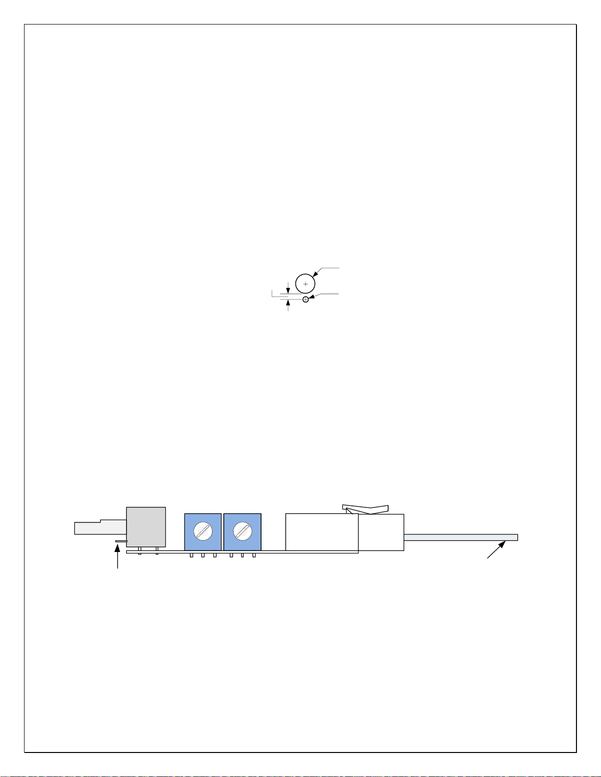
2) Drill a mounting hole and an anti-rotation hole per the drawing in figure 1.
Ø 0.276
Ø 0.081
0.181
Figure 1.
3) Attach the white, 8 pin wiring harness connector to the pcb and then install the
potentiometer shaft thru the mounting hole and add the washer and nut. Rotate the
pcb until the indexing tab on the potentiometer aligns with the anit-rotation hole, then
tighten the pot shaft nut.
4) Strain relieve the wiring harness within 6” of the white 8 pin connector. It is
important that the wiring harness is not pulling on the controller circuit board. Use a
cable tie and mounting plate to secure the wiring harness to the aircraft.
open close
connector
Wire harness
Strain relieve
within 6"
Indexing pin
Figure 2.
(Note: Open and close pots correspond to actuator motion when wire harness colors are
aligned, if you use reverse polarity connection, open and closed pots are reversed)
5) Mount the linear actuator servo using the hardware provided. NOTE: it may be
helpful to temporarily connect the wiring harness to the actuator and apply 12 volts to
Page 3

725.0045 REV 1.4 © 2020 TCW Technologies, LLC.
3
the controller to evaluate the full travel available from the linear actuator. You must
ensure that the travel required to get full motion of the device you are controlling is
available, this can be strongly influence by the mounting location of the actuator and
any control arms on the device. Also note, you can always limit the travel after
installation by utilizing the two blue trimmer potentiometers on the side of the
controller, however you cannot cause addition travel beyond the fixed length of the
linear actuator arm.
When connecting the black 5 pin connector at the linear actuator you can select the
direction the actuator travels with respect to the control knob rotation on the controller
circuit board by simply flipping the connector body over. This connector is nonpolarized and will mate properly in either direction.
NOTE: THESE DRAWINGS ARE FOR THE STANDARD DUTY 30 MM SERVO,
NOT THE 50 MM HEAVY DUTY SERO
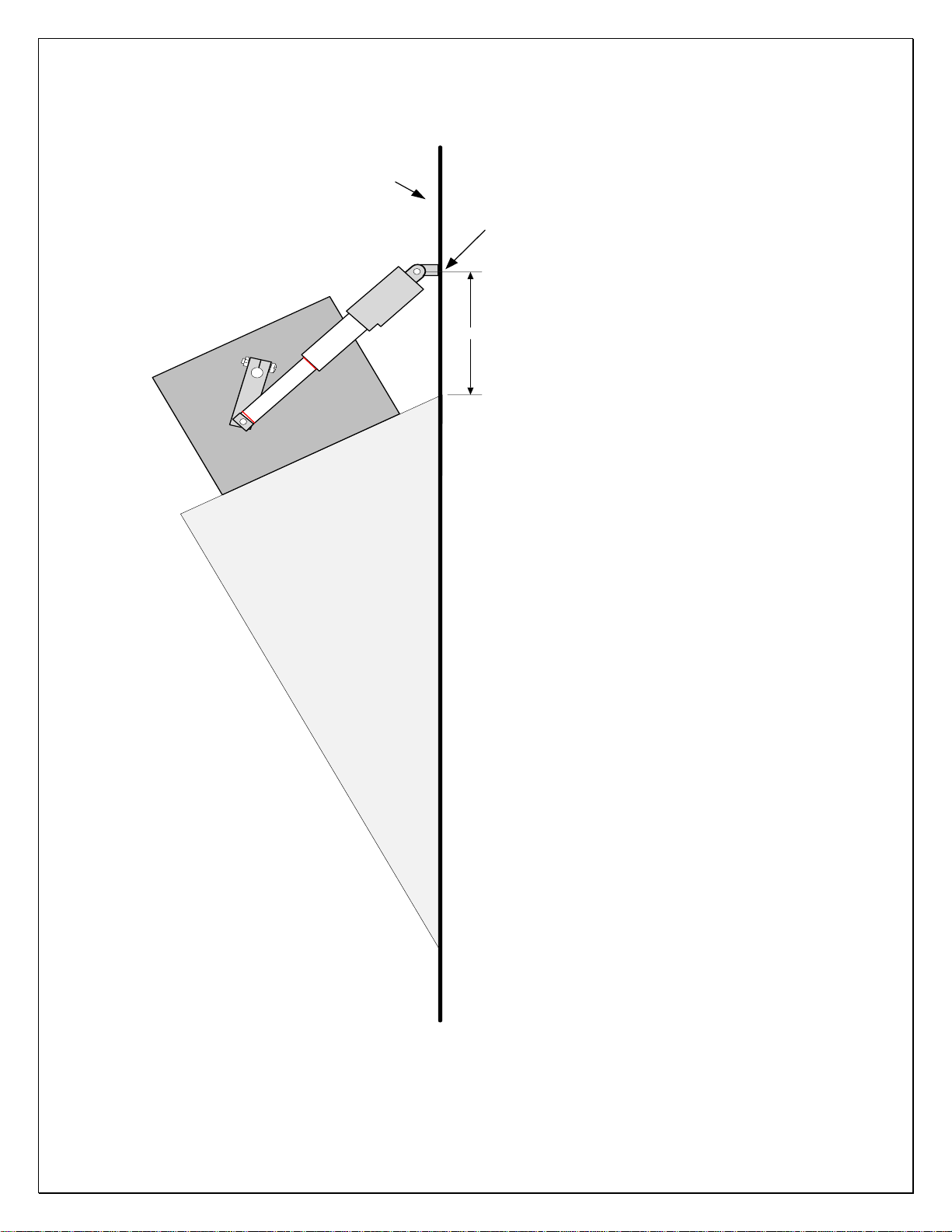
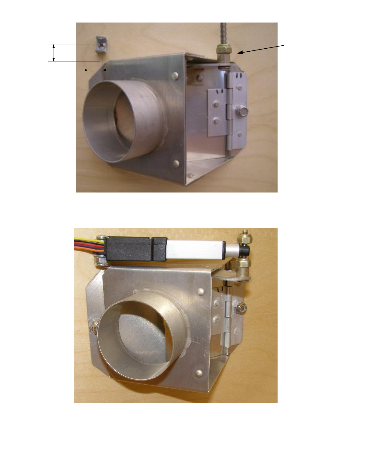
See figures 3, 4, and 5 for examples of mounting the linear actuator. Figure 3 shows
the linear actuator used in conjunction with our 4” butterfly valve for controlling oil
temperature on a Van’s RV-10 system. Figure 4 and 5 shows the linear actuator
being used to control a cabin heat flapper valve on an RV-10. Example dimensions
are shown in the figures for locating the C shaped mounting bracket.
Start the mounting process by attaching the servo to the control arm of heater valve
or oil cooler butterfly valve using the provided hardware. Follow this by temporarily
mounting the C shaped bracket to the other end of the servo. Hold the servo in the
approximate installation location and check the mounting location of the C shaped
bracket. Confirm the mounting location by operating the servo over its full travel,
ensure the valve can move thru the required range of motion. When satisfied with
the motion of the servo, drill a hole for the C shaped bracket and securely bolt in
place. Attach the servo and recheck the full range of motion.
If necessary the travel of the servo can be reduced using the two blue trimmer
potentiometers on the side of the controller.
IMPORTANT NOTES on adjusting the full travel of the servo:
a) Make very small adjustments of the trimmer potentiometers, after each
adjustment run the servo all the way to the opposite end of travel then back to end
being adjusted.
b) Each trimmer is dedicated to adjusting one end of the travel, however, it does
have some influence on the opposite end therefore it is important to make small
adjustments and always check the opposite end after each adjustment.
c) During the trimming process avoid running the servo to the absolute end of travel.
Ensure that the active travel area commanded by the control knob leaves about 1/32”
or more of actuator shaft unused at each end.
d) If during the trimming process you need to get back to the factory shipped
settings, turn both trim pots fully counter- clockwise, then back them off about 1/16” at
the pointer end of the pot.
Page 4

725.0045 REV 1.4 © 2020 TCW Technologies, LLC.
4
6) After completing the travel adjustments route the wiring harness and properly fasten
the wires to the airframe using cable ties. Connect the wiring harness to the linear
actuator and strain relieve the wires. Add a piece of heat-shrink tubing over the black
connector to lock it in place.
7) Connect the two power leads from 8 pin connector to aircraft power and ground.
Connect the red + to aircraft power via a 2 amp fuse or circuit breaker. Connect the
black - flying lead to aircraft ground.
For service or if you have questions, please contact us.
610-928-3420
www.tcwtech.com
email: [email protected]
TCW Technologies, LLC.
2955 Main Road East
Emmaus, PA 18049
Page 5
725.0045 REV 1.4 © 2020 TCW Technologies, LLC.
5
NOTE: THESE DRAWINGS ARE FOR THE STANDARD DUTY 30 MM SERVO,
NOT THE 50 MM HEAVY DUTY SERVO
firewall
2.625
Oil cooler mount
4
"
Butterfly valve
Drill for this bracket
Figure 3. RV-10 oil cooler assembly with CVS system
Page 6
725.0045 REV 1.4 © 2020 TCW Technologies, LLC.
6
0.50
.43
Figure 4. Mount C bracket, install 8-32 x 1.25 bolt with spacer
Figure 5. Servo mounted in C bracket
8-32 x 1.25" bolt
with spacer
Page 7

725.0045 REV 1.4 © 2020 TCW Technologies, LLC.
7
SPECIFICATIONS: CVS-24v-kit-HD series
Input Voltage: 22-30 volts DC
Input Current 0.1 amp
Servo 50 mm max travel
Max drive force 10 lbs.
Max holding force 40 lbs.
Temp range -30 C to +70 C
Weight servo: 1.1 oz.
Controller: 1.0 oz.
SPECIFICATIONS: CVS-24v-kit Standard series
Input Voltage: 22-30 volts DC
Input Current 0.1 amp
Servo 30 mm max travel
Max drive force 2.5 lbs.
Max holding force 10 lbs.
Temp range -30 C to +70 C
Weight servo: 1.1 oz.
Controller: 1.0 oz.
Page 8

725.0045 REV 1.4 © 2020 TCW Technologies, LLC.
8
TCW Technologies, LLC.
During the first 12 months from the date of purchase and subject to the conditions hereinafter set forth, TCW
Technologies, LLC. (TCW) will repair or replace to the original user or consumer any portion of your new TCW product
which proves defective due to defective materials or workmanship of TCW. Contact TCW Technologies for warranty
service. TCW shall have and possess the sole right and option to determine whether to repair or replace defective
equipment, parts or components. Damage due to equipment, environment or conditions beyond the control of TCW
Technologies are NOT COVERED BY THIS WARRANTY.
LABOR, COSTS: TCW shall IN NO EVENT be responsible or liable for the cost of field labor or other charges incurred
by any customer in removing and/or reaffixing any TCW product, part or component thereof.
THIS WARRANTY WILL NOT APPLY: (a) to defects or malfunctions resulting from failure to properly install, operate
or maintain the unit in accordance with printed instructions provided; (b) to failures resulting from abuse, accident, or
negligence; (c) to normal maintenance services and the parts used in connection with such service; (d) to units which are
not installed in accordance good trade practices; or (e) to unit used for purposes other than for what it was designed and
manufactured.
RETURN OR REPLACED COMPONENTS: any item to be replaced under this Warranty must be returned to
TCW Technologies in Emmaus, PA, or such place as TCW may designate, freight prepaid.
PRODUCT IMPROVEMENTS: TCW reserves the right to change or improve its products or any portions
thereof without being obligated to provide such a change or improvement for units sold and /or shipped prior to
such change or improvement.
WARRANTY EXCLUSIONS: as to any specific TCW product, after the expiration of the time period of the
warranty applicable thereto as set forth above. THERE WILL BE NO WARRANTIES, INCLUDING ANY
IMPLIED WARRANTIES OR MERCHANTABILITY OR FITNESS FOR ANY PARTICULAR PURPOSE.
Some states do not allow limitations on how long an implied warranty lasts, so the above limitation may not
apply to you. No warranties or representations at any time made by any representative of TCW shall vary or
expand the provisions hereof.
LIABILITY LIMITATION: IN NO EVENT SHALL TCW OR ITS AFFILIATES BE LIABLE OR RESPONSIBLE
FOR CONSEQUENTIAL, INCIDENTAL OR SPECIAL DAMAGES RESULTING FROM OR RELATED IN ANY
MANNER TO ANY TCW PRODUCT OR PARTS THEREOF. THE SUITABILITY OF USE OF THE TCW
TECHNOLGIES, LLC. PRODUCT IS TO BE DETERMINED BY THE AIRCRAFT BUILDER.
Some states do not allow the exclusion or limitation of incidental or consequential damages, so the above
limitation or exclusion may not apply to you.
This Warranty gives you specific legal rights and you may also have other rights which vary from state to state.
In the absence of other suitable proof of this installation date, the effective date of this Warranty will be based
upon the date of manufacture plus one year. Direct All Notices To: Warranty and Product Service Department,
TCW Technologies, 2955 Main Road East. Emmaus, PA 18049
 Loading...