


Description
The SZ1017N is a thermostat with a 7-day time clock
designed for applications with modulating heating or cooling.
Features
! Stand-alone or network operation
! 7-day time clock
! Discharge air sensor input with high and low limits and
reset
! Outdoor air sensor input with heating & cooling lockout
! Offers up to two stages heating or cooling and a modulating
heating or cooling output
! Adjustable delay on powerup for soft starts
! P+I control option
! Smart Recovery
! No backup battery required
! Built-in HVAC equipment protection
! 32 character LCD display
! Six LEDs for status monitoring
! Remote room sensing capability
! User setpoint adjustment limits
! Local and remote override capability
! System and fan switching with access lockouts
! Fan interlock safety option
! Filter service input and indication
! Equipment monitoring inputs and indication
! External time clock input
! Energy management input for setpoint shift
! Access to programming or schedule may be locked out or
limited with the use of an access code
! Fahrenheit or Celsius temperature display
Product Manual
Contents
Description . . . . . . . . . . . . . . . . . . . . . . . . . . . . . . . . . . . .1
Features . . . . . . . . . . . . . . . . . . . . . . . . . . . . . . . . . . . . . . .1
Mounting . . . . . . . . . . . . . . . . . . . . . . . . . . . . . . . . . . . . . .1
N2 Bus Connections . . . . . . . . . . . . . . . . . . . . . . . . . . . . .2
Wiring . . . . . . . . . . . . . . . . . . . . . . . . . . . . . . . . . . . . . . . .2
Setup . . . . . . . . . . . . . . . . . . . . . . . . . . . . . . . . . . . . . . . . .3
Programming . . . . . . . . . . . . . . . . . . . . . . . . . . . . . . . . . . .4
Setting Clock & Schedule . . . . . . . . . . . . . . . . . . . . . . . . .7
Operation . . . . . . . . . . . . . . . . . . . . . . . . . . . . . . . . . . . . . .7
Checkout & Troubleshooting . . . . . . . . . . . . . . . . . . . . . . .9
LED Description . . . . . . . . . . . . . . . . . . . . . . . . . . . . . . . .11
Limiting Occupant Access . . . . . . . . . . . . . . . . . . . . . . . . .12
User’s Guide . . . . . . . . . . . . . . . . . . . . . . . . . . . . . . . . . . .12
N2 Point Mapping Table . . . . . . . . . . . . . . . . . . . . . . . . . .13
Mounting
The SZ1017N is designed for wall mounting using two #6
sheet metal screws, either over a horizontally installed 2" x 4"
junction box, or directly to block or drywall.
For best results, the SZ1017N should be mounted on an interior wall which reflects normal room environment, at a height
of approximately five feet from the floor. Avoid areas exposed
to direct sunlight, unusual heat sources, open doors and windows, or unventilated locations.
If using a remote room sensor, it should be mounted in the
manner described above. The thermostat may be mounted in
an area which is accessible for adjusting its settings.
R
SZ1017N
Modulating Thermostat
with 7-day Time Clock
Communicating Thermostats
R
2800 LAURA LANE IMIDDLETON, WI 53562 I(800) 288-9383 IFAX (608) 836-9044 Iwww.tcs-basys.com
1

W
iring
The SZ1017N uses standard terminal designations for wiring.
See diagram below.
REMOTE SENSOR WIRING
Use 18 AWG shielded twisted-pair grounded at the sensor
mounting location. Sensor wiring runs of up to 250 feet are
attainable if properly shielded wire is used and the installation
environment is free of electrical noise. Sensor wire should be
kept at least five feet away from line voltage wiring.
The SZ1017N accept two remote sensors. Consult the TS
Series Temperature Sensor Submittal Data sheet for a complete listing of packaging and application styles. When using
TCS/Basys Controls three-wire sensors, use the black and red
leads and either clip or twist off the white lead. Make sure
that the dip switches are set for the sensors you are using.
POWERING THE SZ1017N
The SZ1017N is powered from 24 VAC +/- 20 %.
If wiring for communications, dedicated power must be used
to power the SZ1017N. Several S-series thermostats may be
powered from the same transformer, provided that the transformer has sufficient power, although the polarity must be
kept the same throughout because these are half-wave rectified devices. (SZ1017N thermostats require 8 VA @ 24 VAC).
When the SZ1017N is used as a stand-alone thermostat without communications, the unit transformer may be used to
power it. However, using separate power will eliminate possible ground loops which may damage the thermostat.
Packaged Unit/Modulating Terminations
1
3
4 44
5 5
Zone/Return
Air Temp
Discharge
Air Temp
N2 Bus
R
G
Y1 or
W1
Y2
or
W2
Time Clock
Output
+
-
5
Outdoor
Air Temp
7 6
HWV or CWV
2
CAUTION
When multiple TCS devices are
using a single transformer, the
polarity of the power wiring must
be maintained because all TCS
devices are half-wave rectified
and have common return paths.
!
!
1
2
For communication wiring, use
twisted, shielded 18 AWG.
Must be run separately.
Dry momentary contact.
Must not be powered.
3
4
24 VAC transformer. See powering
instructions.
Dry contact. Must not
be powered.
5
6
Sensor input wiring 18 AWG, twisted, shielded pair.
4 to 20 mA output. 600 ohm max. Do not power actuator with power from the thermostat. The thermostats
are half-wave rectified, whereby the power ground is
common with the signal ground.
Up to nominal 28 VAC from equipment transformer.
R
2800 LAURA LANE IMIDDLETON, WI 53562 I(800) 288-9383 IFAX (608) 836-9044 Iwww.tcs-basys.com
2
7

KEYPAD ACCESS
The dipswitches in the cover (shown above connected with
ribbon cable) must be set in order to lock the user out of
programming and/or to set the clock and schedule. Use the
guide below to set these dipswitches for your application.
Otherwise, user access may be limited with an access code
set in programming. (The fan and system switches are
enabled or disabled in programming only, and require no
dipswitch placement.)
Keypad access to both programming
and clock setup. (This is the default
setting.)
No keypad access to programming or
clock setup.
Keypad access to programming only.
Keypad access to clock setup only.
Once the dipswitches have been set and you have confirmed
that the sensors are reading correctly (and program and
clock setup are finished, if locking out access with dipswitches), secure the cover to the base with the two set
screws located at the top right and the left side to prevent
tampering.
Setup
Note: If using remote sensor(s), the calibration may need to
be adjusted. See “Checkout and Troubleshooting” section.
SENSOR SELECTION
The dipswitches in the cover (shown above connected with
ribbon cable) as well as the programming must be set when
using remote room, discharge, and/or outdoor sensors. Use
the following guide to determine
the dipswitch settings for your
application.
Using built-in room sensor only.
(This is the default setting.)
Using built-in room sensor with
discharge air sensor only.
Using built-in room sensor with
outdoor air sensor only.
Using built-in room sensor with
both discharge and outdoor air
sensors.
Using remote room sensor only.
Using remote room sensor with
discharge air sensor only.
Using remote room sensor with
outdoor air sensor only.
Using remote room sensor with
both discharge and outdoor air
sensors.
1 2 3 4 5
1 2
1
2
3
4
5
1 2
R
2800 LAURA LANE IMIDDLETON, WI 53562 I(800) 288-9383 IFAX (608) 836-9044 Iwww.tcs-basys.com
3

Programming
The SZ1017N may be programmed through the display and
keypad, or with a PC.
If programming with a PC, the following must be set
through the keypad prior to programming:
! Address (step #3)
! Temperature scale (step #4)
For more information on programming through the PC, consult your software manuals.
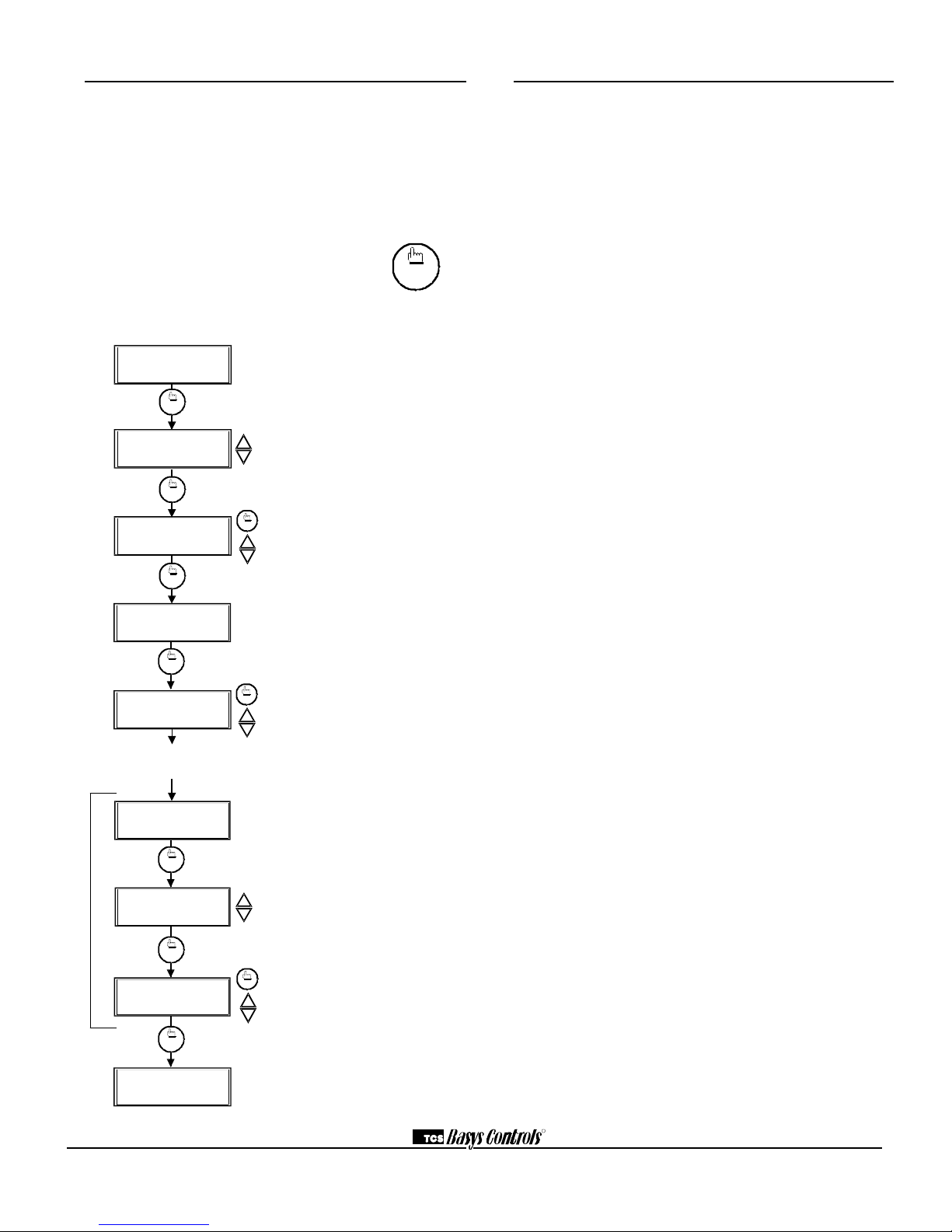
PROGRAMMING THROUGH THE KEYPAD
To access the programming screens, press the program setup
button. To make changes, use the warmer and cooler keys.
Access may be locked out with dipswitches, or an access
code may be required.
fan
Occup ied
Heating
Cooling
Fan
Service
Program/
COOLER
WARMER
Data
switch
system
switch
program
setup
clock
setup
override
service
status
program
setup
program
setup
SET ADDRESS:
000
2.
ENTER ACCESS
000
1.
CODE
MON
72F
12:00 AM
program
setup
3.
program
setup
program
setup
program
setup
program
setup
program
setup
program
setup
program
setup
11.
UNOCCUPIED HEAT
SETPOINT: 60F
OCCUPIED HEAT
10.
SETPOINT: 68F
SET UNOCCUPIED
FAN MODE: AUTO
9.
8.
SET OCCUPIED FAN
MODE: ON
USER ACCESS TO
FAN MODE? YES
7.
SET SYSTEM
6.
MODE: AUTO
USER ACCESS TO
5.
SYSTEM MODE? YES
TEMPS SHOWN IN:
4.
FAHRENHEIT
program
setup
Main Monitoring Screen. Press the pro-
gram setup button to access the following
screens.
Access Code Entry Screen. Will appear
if access code is required for programming.
Use 248 as the default. If the wrong code is
entered, it will revert to the previous screen.
Controller Address Screen. If using a PC
to access the SZ1017N, set a unique
address from 1 to 255.
Display Type Screen. Choose between
FAHRENHEIT and CELSIUS for temperature indication.
System Access Screen. Choose whether
or not to enable user’s access to the system switch to set the system mode.
System Mode Screen. Choose from
AUTO, HEAT, COOL, or OFF for system
mode. In the OFF mode, all outputs are off.
Fan Access Screen. Choose whether or
not to enable the user’s access to the fan
switch to set the occupied fan mode.
Occupied Fan Mode Screen. Choose
between ON (continuous), COOL (gas heat
or no heat), or AUTO for your fan run times
during the occupied modes.
Unoccupied Fan Mode Screen. Choose
from AUTO or COOL for fan run times in
the unoccupied mode.
Occupied Heat Setpoint Screen. Set the
occupied heat setpoint.
Unoccupied Heat Setpoint Screen. Set
the unoccupied heat setpoint.
R
2800 LAURA LANE IMIDDLETON, WI 53562 I(800) 288-9383 IFAX (608) 836-9044 Iwww.tcs-basys.com
4

program
setup
program
setup
program
setup
program
setup
program
setup
program
setup
program
setup
program
setup
30.
DISCHARGE AIR
LOW LIMIT: 45F
29.
28.
ENABLE DISCHARGE
AIR SENSOR? YES
SETPOINT
OFFSET: 00F
27.
UNOCCUPIED ACTION
25.
MODULATING
MODULATING OUT
RANGE: 4-20 MA
24.
OUTPUT ACTION:
.
DIRECT
22.
MODULATING OUT
IS: COOL
21.
SET CONTROL
MODE: P+I
23.
program
setup
PROPORTIONAL
BAND: 5F
26.
program
setup
TIME CLOCK OUTPUT
OCCUPIED=CLOSED
program
setup
program
setup
program
setup
program
setup
program
setup
program
setup
program
setup
program
setup
STAGE 2
DIFF: 2F
20.
STAGE 2
OFFSET: 2F
19.
18.
STAGE 1
DIFF: 2F
STAGE 1
OFFSET: 0F
17.
STAGE OUTPUT 1&2
16.
AS: HEAT
SET OVERRIDE
TIME: 180 MINUTES
15.
LIMIT SETPOINT
14.
ADJUST +/-: 5F
13.
UNOCCUPIED COOL
SETPOINT: 80F
12.
OCCUPIED COOL
SETPOINT: 72F
program
setup
Occupied Cool Setpoint Screen. Set
the occupied cool setpoint.
Unoccupied Cool Setpoint Screen.
Set the unoccupied cool setpoint.
User Setpoint Limit Screen. Enter
the number of degrees you want the
user to be allowed to change the preset occupied setpoints up or down.
Override Time Screen. Enter the
number of minutes (0 to 255) that the
SZ1017N will maintain occupied setpoints when overridden.
Stage Mode Screen. Choose whether
stages 1 and 2 perform heating or
cooling functions, or whether both
stages are to be disabled.
Stage 1 Offset Screen. Enter an offset value for stage 1. First stage is normally 0 offset. This screen does not
appear if stage outputs 1 and 2 are
disabled.
Stage 1 Differential Screen. Enter a
differential value for stage 1. This
screen does not appear if stage outputs 1 and 2 are disabled.
Stage 2 Offset Screen. Enter an offset value for stage 2. This screen does
not appear if stage outputs 1 and 2 are
disabled.
Stage 2 Differential Screen. Enter a
differential value for stage 2. This
screen does not appear if stage outputs 1 and 2 are disabled.
Control Mode Screen. Enter whether you
want to control by temperature only (P) or
add a time factor (P+I). This applies to both
the stage outputs.
Time Clock Output Screen. Choose
whether the auxiliary output will be OPEN
during occupied periods (and closed during
unoccupied periods) or CLOSED during
occupied periods (and open during unoccupied periods).
Modulating Output Define Screen.
Choose whether the modulating output will
be used for COOL, HEAT or AQUASTAT.
With DI2 set to AQUASTAT, the analog output will be used for cooling with DI2 open
and heating with DI2 closed.
Modulating Output Action Screen.
Choose whether the output will be direct or
reverse acting. (When DI2 is set to AQUASTAT, the output will automatically reverse
action when DI2 is closed.)
Modulating Output Range Screen.
Choose whether the modulating output
range will be 0-20 mA or 4-20 mA.
Unoccupied Action Screen. Choose
whether the unoccupied action will be modulating, 0 or 4 mA, or 20 mA.
Modulating Output Proportional Band
Screen. Enter the number of degrees away
from the setpoint that the valve or damper
will be fully open.
Analog Output Setpoint Offset Screen.
Enter a setpoint offset. This is a value below
the heating setpoint or above the cooling
setpoint where the analog output begins to
modulate.
Discharge Air Sensor Screen. Choose whether
or not you are using the discharge air sensor
function. To monitor only, select no.See setup
instructions for dipswitch settings which must also
be set.
Discharge Air Low Limit Screen. Enter a
discharge air low limit value. This screen
will not appear if the discharge air sensor
function is disabled.
R
2800 LAURA LANE IMIDDLETON, WI 53562 I(800) 288-9383 IFAX (608) 836-9044 Iwww.tcs-basys.com
5

program
setup
program
setup
program
setup
program
setup
program
setup
program
setup
program
setup
program
setup
39.
DI2 USED FOR:
SERVICE
38.
37.
DI1 USED FOR
FAN PROVING
HEATING LOCKOUT
TEMP: 70F
36.
COOLING LOCKOUT
35.
TEMP: 80F
ENABLE OUTDOOR
AIR SENSOR? YES
34.
RESET RATIO
33.
FACTOR: 2F
32.
DISCHARGE AIR
SETPOINT: 90F
31.
CONTROL BASED
ON: SPACE
DISCHARGE AIR
HIGH LIMIT: 120F
program
setup
program
setup
program
setup
program
setup
program
setup
program
setup
program
setup
MON
12:00 AM 72F
45.
SET ACCESS
CODE: 000
44.
REQUIRE CODE FOR
CLOCK / SCHED? YES
43.
ENABLE SMART
YES
RECOVERY?
REQUIRE CODE FOR
PROGRAMMING? YES
42.
DELAY ON POWERUP
60 SECONDS
ENABLE SMART
RECOVERY? YES
DI3 USED FOR:
FILTER SERVICE
41.
DELAY ON POWERUP
60 SECONDS
DI3 USED FOR:
FILTER SERVICE
40.
DI3 USED FOR:
FILTER SERVICE
program
setup
DI3 USED FOR:
FILTER SERVICE
SET DI2 SETPOINT
SHIFT: 02F
46.
Discharge Air High Limit Screen. Enter
a discharge air high limit value. This
screen will not appear if the discharge air
sensor function is disabled.
Discharge Air Reset Screen. Choose
whether to control based on DISCHARGE air reset or SPACE temperature. This screen will not appear if the
discharge air sensor function is disabled.
Discharge Air Setpoint Screen. Enter a
value at which the discharge air setpoint
is to be controlled. This screen will not
appear if the control is based on space
temperature.
Reset Ratio Factor Screen. Enter a
reset ratio factor. This is the number of
degrees that the discharge air setpoint is
raised when the space temperature falls
by 1 degree for heating, or the number of
degrees that the discharge air setpoint is
lowered when the space temperature
rises by 1 degree for cooling.
Outdoor Air Sensor Screen. Choose
whether or not you are using an outdoor
air sensor function To monitor only,
select no. See setup instructions for dipswitch settings which must also be set.
Cooling Lockout Screen. Enter an outdoor air cooling lockout temperature.
This screen will not appear if the outdoor
air sensor function is disabled.
Heating Lockout Screen. Enter an outdoor air heating lockout temperature.
This screen will not appear if the outdoor
air sensor function is disabled.
DI1 Choice Screen. Choose DI1 as FAN
PROVING or a MONITOR point. Select
MONITOR if unused.
DI2 Choice Screen. Choose DI2 as
SERVICE, AQUASTAT, or MONITOR.
Select MONITOR if unused.
DI2 Shift Screen. Enter the setpoint shift
value. This screen will only appear if DI2
is set to MONITOR.
DI3 Choice Screen. Choose FILTER SERVICE, EXTernal OVERRIDE, or EXTernal
TIME CLOCK. Select FILTER SERVICE if
unused.
Delay On Powerup Screen. Enter a
value in seconds, such that when the
unit is powered up, no control starts for
this amount of time.
Smart Recovery Screen. Choose
whether or not smart recovery will be
used. Note: Smart Recovery is not avail-
able when DI3 is used as EXTernal TIME
CLOCK.
Programming Access Screen. Choose
whether or not a code will be required to
enter programming setup. A dipswitch
option to lock out access altogether is also
available.
Clock and Schedule Access Screen.
Choose whether or not a code will be
required to enter clock and schedule
setup. A dipswitch option to lock out
access altogether is also available.
Access Code Screen. Enter an access (0
to 255) code that will be used to enter the
programming and/or clock and schedule
setups if access code has been required in
the last two steps. The default is 248.
Main Monitoring Screen.
R
2800 LAURA LANE IMIDDLETON, WI 53562 I(800) 288-9383 IFAX (608) 836-9044 Iwww.tcs-basys.com
6
Setting Clock & Schedule
The SZ1017N clock and schedule may be set through the
keypad on the face, or with a PC. For more information on
programming through the PC, consult your software manual.
SETTING CLOCK & SCHEDULE
THROUGH THE KEYPAD
To access the clock and schedule screens, press the clock
setup button. To make changes, use the warmer
and cooler keys. For screens that have more
than one field to set, use the override key to
move to the next field. Access may be locked
out with dipswitches, or an access code may be required.
clock
setup
Main Monitoring Screen. Press the
service button to access the following
screens.
Access Code Entry Screen. May
appear if access code is required for
setting clock and schedules. Use 248
as the default. If the wrong code is
entered, it will revert to the previous
screen.
Time and Day Screen. Set the hour,
minutes, AM or PM, and day of the
week.
Schedule Announcement Screen.
Announces the next screen.
Occupied Times Screen. Set hours
and minutes of start and end times for
up to two occupied periods.
Schedule Announcement Screen.
Announces the next screen.
Copy Schedule Screen. Choose to
use the same schedule that was used
for the previous day. If so, the next
screen does not appear.
Occupied Times Screen. Set hours
or minutes of start and end times for
up to two occupied periods.
Main Monitoring Screen.
MON
72F
12:00 AM
3.
1.
clock
setup
ENTER ACCESS
SET TIME & DAY:
MON12:00 AM
2.
000
CODE
override
clock
setup
clock
setup
SET OCCUPIED
A:08:00 TO 12:00
4.
5.
TIMES MONDAY:
B:13:00 TO 17:00
SET OCCUPIED
6.
TIMES TUESDAY:
The following screens are repeated for
Wednesday, Thursday, Friday, Saturday
and Sunday.
COPY MON FOR
TUE? YES
7.
MON
72F
12:00 AM
A:08:00 TO 12:00
B:13:00 TO 17:00
clock
setup
override
clock
setup
clock
setup
clock
setup
override
Operation
UNOCCUPIED SETBACK
The SZ1017N operates in either an occupied or unoccupied
mode. During the occupied mode, the occupied heating and
cooling setpoints will be maintained, and the fan will operate according to its occupied setting. During the unoccupied
mode, the unoccupied heating and cooling setpoints will be
maintained, and the fan will operate according to its unoccupied setting. The occupied LED will be lit when the unit
is operating in the occupied mode.
The occupied schedule may be set utilizing the internal time
clock or DI3 may be used with an external time clock,
whereas when DI3 is closed, the unit is in the occupied
mode. The Smart Recovery function is disabled when DI3
is used for external time clock.
OVERRIDE
A timed override is available on the keypad or through
momentary N.O. contacts. The amount of time the unit will
be overridden is set from 0 to 255 minutes in the programming. This override only activates when the thermostat is
operating in the unoccupied mode. Both the software and
the service button allows you to view the time remaining in
the override mode. If the occupant desires to return the thermostat to unoccupied operation before that time interval is
up, they may press the button on the keypad or the momentary contact again.
Continuous override is available using DI3. If DI3 is set to
external override, the unit will be in the occupied mode
whenever the DI3 contact is closed. When using this option,
the timed override may still be activated.
The software allows you to override the thermostat by
putting the override parameter into the remote mode, and
thus disabling the timed override.
SETBACK AND OVERRIDE APPLICATIONS
In most applications, it is desired to maintain a regular
schedule, and allow timed override with the button on the
face or with a remote momentary contact.
To allow a regular schedule, and also automatically override
with the use of occupancy or light sensor, set DI3 to override and set it up so that the contact is closed when you
want the override.
For applications where a room might not be used on a regular schedule, such as conference rooms, set DI3 to time
clock and close the contact when you want the room occupied, such as with a switch or wind-up timer. If each occupancy period is about the same, (theaters, meetings) another
option is to set the DI3 to time clock, and use the timed
override button to put the unit in occupied mode.
To make the unit always occupied, set DI3 to time clock
and short the DI3 terminal to ground.
R
2800 LAURA LANE IMIDDLETON, WI 53562 I(800) 288-9383 IFAX (608) 836-9044 Iwww.tcs-basys.com
7

air temperature rises 2° above the lockout temperature. If
the outdoor temperature rises above the HEATING LOCKOUT TEMP, all heating stages will be locked out and will
remain locked out until the outdoor air temperature falls 2°
below the lockout temperature.
The outdoor air span is -40 to 160 °F (-40.0 to 71.1 °C).
FAN PROVING
The SZ1017N allows DI1 to be set for fan proving to protect equipment on fan failure. To utilize this, a pressure or
current switch is required, which indicates when the fan is
running. If the thermostat turns on the FAN, and DI1 is not
closed after thirty seconds, the system will go to OFF, disabling all outputs, the fan LED will turn off, and the service
LED will be lit until the system is manually reset by
switching the system to a mode other than OFF.
DI2 SETPOINT SHIFT
The SZ1017N allows DI2 to be set for setpoint shift for
energy demand setback. This is enabled by setting DI2 to
the MONITOR mode. A digital contact that closes when
setback is needed should be wired into DI2. You may specify a number of degrees such that, when the thermostat is
operating in the occupied mode, and DI2 is closed, the
heating setpoint will be lowered this number of degrees,
and the cooling setpoint will be raised this number of
degrees. The fan will continue to operate according to its
occupied setting. If you are using DI2 as monitor for another purpose, make sure to set the setpoint and shift value to
zero.
STAGE OUTPUT PARAMETERS
The SZ1017N will control up to two stages of either heating or cooling.
For each stage, you may specify an offset and a differential
value. The offset value is the amount away from the setpoint a stage will turn off. By assigning a stage a value
other than zero, you “anticipate” that the residual heat or
cooling in the duct or the other stages will bring the temperature back to setpoint. In most cases, the first stage is set
to zero. The differential value is the difference between the
on and off points.
DISCHARGE AIR TEMPERATURE SENSING
The SZ1017N accepts a remote 1000 Ω discharge air sensor
(TS1009 or TS1002) for monitoring purposes. (See setup
instructions for dipswitch placement for this option.)
Choose YES in programming screen #28 only if you are
using a discharge air sensor and you want to enable the discharge air temperature high and low limit functions or discharge air reset function. See Discharge Air Reset section
for further programming options. If NO is chosen, the discharge air is still monitored.
When the function is enabled, a LOW LIMIT and HIGH
LIMIT are entered in steps #29 and #30. If the HIGH
LIMIT is reached, the fan and heating stages will be turned
off and will remain off until the discharge air temperature
falls 3° below that limit. If the LOW LIMIT is reached, the
fan and cooling stages will be turned off and will remain off
until the discharge air rises 3° above that limit. When either
limit is reached, the service LED will be on until normal
operation resumes.
The discharge air span is 0 to 150 °F (-17.8 to 65.6 °C).
ANALOG OUTPUT / DISCHARGE AIR RESET
The analog output on the SZ1017N is used to control the
heating or cooling in a space. To use the discharge air reset
function, a discharge air sensor must be installed. In programming step #28, the discharge air sensor must be
enabled. In programming step #31, the control must be
based on DISCHARGE air.
In programming screen #32, you are asked to enter a discharge air setpoint. The discharge air temperature will be
controlled to this setting by modulating the heating or cooling device.
In programming screen #33, you are asked to enter a reset
ratio factor. This is the number of degrees that the discharge air setpoint is raised when the room temperature falls
below the heating setpoint by 1 degree if the analog output
is set for heating, or the number of degrees that the discharge air setpoint is lowered when the room temperature
rises above the cooling setpoint by 1 degree if the analog
output is set for cooling.
OUTDOOR AIR TEMPERATURE SENSING
The SZ1017N accepts a remote 1000 Ω outdoor temperature sensor (TS1003) for monitoring purposes. (See setup
instructions for dipswitch placement for this option.)
Choose YES in programming screen #34 only if you are
using an outdoor air sensor and you want to enable the outdoor air heating and cooling lockout functions. If NO is
chosen, the outdoor air is still monitored.
When the function is enabled, a COOLING LOCKOUT
TEMP and HEATING LOCKOUT TEMP are entered in
steps #35 and #36. If the outdoor temperature falls below
the COOLING LOCKOUT TEMP, all cooling stages will
be locked out and will remain locked out until the outdoor
Heat Setpoint
Cool Setpoint
ON
ON
ON
ON
OFF
OFF
OFF
OFF
Differential
Differential
Offset
Offset
Differential
Differential
R
2800 LAURA LANE IMIDDLETON, WI 53562 I(800) 288-9383 IFAX (608) 836-9044 Iwww.tcs-basys.com
8

ANALOG OUTPUT PARAMETERS
Use programming steps #22 through #26 to program the
operating parameters for the analog output. Select whether
the analog output is set for heating, cooling or aquastat.
Select direct or reverse action. Select whether you want the
analog output to modulate from 4 to 20mA or 0 to 20mA.
Select the unoccupied action ("20mA or 0 / 4mA" will hold
the analog output device open or closed during unoccupied
times. "Modulating" will modulate the analog output device
to maintain the unoccupied heating or cooling setpoint.).
Enter a proportional band (throttling range) in degrees.
P+I OPTION
The SZ1017N also has a P+I option. Without enabling this
option, stages turn on and off based on temperature vs. setpoint alone, as described above. By enabling this option,
you add a time factor to anticipate heating and cooling.
DI2 AQUASTAT
DI2 may be set as an aquastat function. When DI2 is selected to have an aquastat function, and the analog output is
selected to have an aquastat function, operation is as follows.
With DI2 "Open", the analog output operates in cooling
mode, and uses selected direct or reverse action. When DI2
is "Closed", the analog output operates in heating mode, and
uses the opposite of the selected direct or reverse action.
SMART RECOVERY
“Smart Recovery” may be enabled. It ramps the setpoint
4°F/hr. when going from the unoccupied mode to the occupied mode. At the beginning of the occupied mode, the
occupied setpoint will be reached, many times without the
need for the second stage to come on. This feature is automatically disabled when DI3 is set to external time clock.
BUILT-IN DELAYS
The SZ1017N has delays built into the programming
sequences to protect equipment. The fan has a minimum on
and off time of 30 seconds. When the fan is in AUTO or
COOL mode, it will come on 30 seconds before the heating
or cooling stages are allowed to sequence on, and remain on
for 30 seconds after the heating or cooling stages sequence
off. Each stage has a minimum on and off time of two minutes. There is a minimum of two minutes between when one
stage turns on until the next stage is allowed to turn on, as
well as when one stage turns off until the next stage is
allowed to turn off.
DELAY ON POWERUP
The SZ1017N has an adjustable delay on powerup. When
several thermostats are used at one location, and the power
goes out, most thermostats turn all of the units back on at
the same time on regain of power, creating a peak. The thermostat allows you to set a value, in seconds, where no outputs are allowed to turn on for that length of time on
powerup. Setting each unit to a different delay allows you to
soft start your system, and thus prevent this peak.
Checkout & Troubleshooting
CHECKOUT
Note: The fan has a minimum on and off time of 30 seconds. The heating and cooling stages have a minimum on
and off time of 2 minutes.
You may verify the status of heating and cooling stages and
fan in monitoring screens 5, 6, and 7, which are accessed by
pressing the SERVICE STATUS button.
1.Verify all wiring prior to powering the thermostat.
2. Turn power on. The thermostat will display a momentary
screen with the model number , and then the main monitoring screen with the time, day and current temperature.
4 20
4 20
4 20
4 20
4 20
4 20
P
Z
o
n
e
T
e
m
p
Output
(mA)
P
Output
(mA)
DIRECT ACTING
REVERSE ACTING
P
P
Output
(mA)
Output
(mA)
Z
o
n
e
T
e
m
p
P
P
Output
(mA)
Output
(mA)
P
P
Z
o
n
e
T
e
m
p
CSP
CSP
HSP HSP
CSP
CSP
HSP HSP
" SZ1017N "
R
2800 LAURA LANE IMIDDLETON, WI 53562 I(800) 288-9383 IFAX (608) 836-9044 Iwww.tcs-basys.com
9

3. Press the PROGRAM SETUP button until you reach the
screen # 14 which allows you to set the occupant setpoint adjustment limits. Change this to +/-20 °F (11.1
°C). Press the PROGRAM SETUP button once more to
store the change. Then press the SERVICE STATUS button once to exit the programming.
4. Press the FAN SWITCH button to access the fan mode
and change the mode to AUTO. Press the FAN SWITCH
button once more to store the change. Press the SYSTEM SWITCH button to access the system mode and
change the mode to AUTO. Press the SYSTEM
SWITCH button once more to store the change.
5. Verify that the thermostat is operating in the occupied
mode by making sure that the top LED is lit. If not, press
the OVERRIDE button. The LED should light up.
6. Take note of the current temperature reading. Press the
WARMER (up) button. The setpoint adjustment screen
should now be showing. Press the WARMER button
until the heating setpoint is greater than the current temperature by at least five degrees. The fan will come on.
The heating stage(s) will sequence on after 30 seconds.
7. Press the cooler (down) button until the heating setpoint
is one degree less than the current temperature. The heating stage(s) will sequence off. The fan will turn off 30
seconds after the last heating stage.
8. Press the cooler button until the cooling setpoint is less
than the current temperature by at least five degrees. The
fan will come on. The cooling stage(s) will sequence on
after 30 seconds.
9. Press the warmer button until the cooling setpoint is
greater than the current temperature by one degree. The
cooling stage(s) will sequence off. The fan will turn off
30 seconds after the last cooling stage.
10. Take note of the room (and discharge) air temperatures.
If the analog output is set for Cooling, press the Cooler
button until the cooling setpoint is less than the current
room temperature by at least 5°. The cooling device
should start operating. If the analog output is set for
Heating, press the Warmer button until the heating setpoint is greater than the current room temperature by at
least 5°. The heating device should start operating.
11. Go back to programming step #14 and set the setpoint
adjust limit back to the desired value. Make any other
changes in programming, clock, and schedule. Set the
fan and system modes to their desired settings.
12. If using remote sensors, verify that the reading is correct. If not, see Wrong Temperature Display in
“Troubleshooting” section.
TROUBLESHOOTING
No Display
Check for 24 VAC on terminals “+24” and “-24”. Check the
cable connecting the cover to the base for a good connection.
Fan Does Not Come On
The fan is on whenever the fan LED is on. If the fan should
be on, but the fan LED is off, check the fan and system switch
modes, and the unoccupied fan mode in programming. If the
fan is off but the fan LED is on, check wiring. Short terminals
“R” to “G” and see if the fan comes on. This is a check for a
mechanical relay failure.
Heating or Cooling Does Not Come On
At least one stage of heating is on whenever the heating LED
is on, and at least one stage of cooling is on whenever the
cooling LED is on. If heating or cooling should be on but the
heating or cooling LED is off, check the fan and system
switch modes. Also, check the heating and cooling setpoints,
offsets and differentials, and the room temperature to be sure
heating or cooling should be on. If using outdoor air heating
and cooling lockouts, or discharge air high and low limits,
check their values to be sure heating or cooling is allowed. If
heating or cooling is off, but the corresponding LED is on,
check the wiring. Short terminals “R” to “Y/W1” or “Y/W2”
and see if the heating or cooling comes on. This is a check for
a mechanical relay failure.
Wrong Temperature Display
If any of the temperatures is reading slightly high or low, there
are three adjustment pots located in the cover to adjust them.
“T1” is for the room temperature, “T2” is for the discharge air
temperature, and “T3” is for the outdoor air temperature. If the
temperature is at a minimum or maximum reading, check the
sensor dipswitch positions. (See setup instructions.) Check for
wiring problems (opens or shorts). A remote 1000 Ω sensor
should read 1080 to 1090 Ω at room temperature. The built-in
sensor should read 108 to 109 Ω at room temperature.
Service LED is On
If the service LED is on, it may be for monitoring purposes or
it may indicate a critical problem. The first monitoring screen
accessed by pressing the service status button will display why
the light is on.
Outputs Will Not Shut Off
First check the room temperature and the setpoints and determine whether the output should be on. There are delays and
minimum on and off times for the fan and heating and cooling
stages. Also, check the service status menus to verify that the
outputs are on. Turning the system to “off” will instantly turn
all outputs off. The thermostat can be reset by pressing the
system switch button and the service status button simultaneously.
R
2800 LAURA LANE IMIDDLETON, WI 53562 I(800) 288-9383 IFAX (608) 836-9044 Iwww.tcs-basys.com
10

Analog Output Not Working Properly
Check wiring. A separate transformer should be used for the
SZ1017N and a separate transformer should be used for the
damper motor(s). Check to make sure that the analog output is
programmed correctly.
Check the Service Menu. The Mod Out Screen will tell you
what the SZ1017N is trying to put out for an output.
Compare this with the actual position of the heating or cooling device.
SERVICE SCREENS
Continually pressing the service status button allows more
extensive monitoring. The screens are shown at right.
LED Description
Six LEDs on the face allow the occupant to view the current
operating status of the thermostat.
OCCUPIED
This LED will be lit whenever the unit is operating in the
occupied mode.
HEATING
This LED will be lit when any heat output is on.
COOLING
This LED will be lit when any cooling output is on.
FAN
This LED will be lit when the fan output is on.
SERVICE
This LED will be lit when the high or low discharge air
limit has been reached, when the fan interlock has indicated
failure, or when the filter service or service input are closed.
PROGRAM/DATA
This LED will be lit when the thermostat is within the programming or clock setup menus. It will blink when the unit
is being accessed by a PC.
Additional monitoring is available by continually pressing
the service key.
MON
72F
12:00 AM
DISCHARGE AIR
55F
OUTDOOR AIR
OVERRIDE ON
178 MINUTES
75F
HEAT STAGE 1 OFF
MOD OUT 100%
SERVICE STATUS
OK
TEMP
1.
2.
3.
4.
5.
6.
7.
TEMP
HEAT STAGE 2 OFF
DI1 OPEN
DI2 SERVICE OFF
FILTER OK
MON
72F
12:00 AM
fan
Occupied
Heating
Cooling
Fan
Service
Program/
COOLER
WARMER
Data
switch
system
switch
program
setup
clock
setup
OVERRIDE
service
status
service
status
service
status
service
status
service
status
service
status
service
status
service
status
service
status
Main Monitoring Screen. Press the service
button to access the following screens.
Service Screen. This message may be followed by any or all of the following: CHECK
FILTER, CHECK FAN, DISCHARGE HIGH,
DISCHARGE LOW, or CHECK DI2.
Discharge Air Temperature Screen.
Shows discharge air temperature if sensor
is used.
Outdoor Air Temperature Screen. Shows
outdoor air temperature if sensor is used.
Override Status Screen. Shows whether
the override is active and if so, how many
minutes remaining.
Heat or Cool Stages Status Screen.
Shows the status of the first and second
stages of heating or cooling.
Mod Out and DI1 Screen. Shows the percentage of modulating output and the status
of the fan interlock, or DI1.
DI2 and DI3 Status Screen. Shows DI2
status and filter status or DI3 status.
Main Monitoring Screen.
R
2800 LAURA LANE IMIDDLETON, WI 53562 I(800) 288-9383 IFAX (608) 836-9044 Iwww.tcs-basys.com
11

User’s Guide
Inside the hinged door of
the thermostat is the
SuperstatTMUser’s Guide.
This guide is designed to
assist the installer in
explaining to the end user
how to operate their new
thermostat, as well as serve
as a handy future reference
for the end user.
We recommend that the installer fill out pages 1, 5, 7 and 8
(where applicable) and explain to the user how the thermostat operates, what settings may be changed, and how the
time clock schedules are used.
Limiting Occupant Access
SETPOINT ADJUSTMENT
The occupant may temporarily change the occupied heating
and cooling setpoints +/- 5°F by factory default. This setpoint change will remain until the end of the current occupied period, at which time the program reverts to the setpoints defined in programming. To change the range of
adjustment allowed, see programming step # 14.
OVERRIDE
The occupant has the ability to put the unit into occupied
mode by pressing the override button on the front. By factory default, the unit will remain in the occupied mode for
180 minutes. This value may be changed from 0 to 255
minutes in programming step # 15.
FAN SWITCHING
The option to allow the occupant to change the occupied fan
mode is allowed by factory default. To lock out access to
fan switching, see programming step #7.
SYSTEM SWITCHING
The option to allow the occupant to change the system
mode is allowed by factory default. To lock out access to
system switching, see programming step #5.
SETTING CLOCK & SCHEDULE
The ability to set the clock and schedule is allowed by factory default. An access code may be required as set in programming step # 44, or access may be denied altogether
using dipswitches described in the setup section.
PROGRAMMING
The ability to program control parameters is allowed by factory default. An access code may be required as set in programming step # 43, or access may be denied altogether
using dipswitches described in the setup section.
SUPERSTAT
TM
POINT MAPPING TABLES
SZ1017N............................Pages 13 - 15
TCS/Basys Controls Technical Support
800-288-9383
R
2800 LAURA LANE IMIDDLETON, WI 53562 I(800) 288-9383 IFAX (608) 836-9044 Iwww.tcs-basys.com
12

Pointmap Table for SZ1017N
NPT
NPA UNITS
POINT DESCRIPTION RANGE/VALUE ADDITIONAL NOTES
ADI 1 # DI2 control mode 0=Aquastat, See programming step #39.
1=monitor, 2=service
ADI 2 # Unocc Analog output action 0=0or4 mA, 1=20 mA See programming step #26.
2=Modulating
ADI 3 # Analog output mode 0=heat, 1= cool, See programming step #23.
2=Aquastat
ADI 4 # DI3 control mode 0=filter service, See programming step #41.
1=external override,
2= external timeclock
ADI 5 # Occupied Fan mode 0=on, 1=cool, 2=auto "Fan Switch" button on keypad.
ADI 6 # System mode 0=off,1=auto,2=heat "System Switch" button on keypad.
3=cool
ADI 7 Day Internal time clock "day" 0-6, mon to sunday Day of Week.
ADI 8 Hours Internal time clock "hours" 0-23 0-12 (AM), 13-23 (PM).
ADI 9 DegF Setpoint adjust limit from keypad 0-50 Limits keypad adjustment of occupied
heating and cooling setpoints.
ADI 10 DegF Differential for stage 1 0-50
ADI 11 DegF Offset for stage 1 0-50
ADI 12 DegF Differential for stage 2 0-50
ADI 13 DegF Offset for stage 2 0-50
ADI 14 DegF Setpoint shift value 0-50 When DI2 is selected "Monitor", this is
number of degrees that the occupied
cooling setpoint is shifted up and the
heating setpoint is shifted down.
ADI 15 DegF (space) Setpoint offset 0-50 See programming step #28.
ADI 16 DegF AO Proportional Band 0-50 See programming step #27.
ADI 17 Seconds Internal time clock "second" 0-59
ADI 18 Minutes Internal time clock "minute" 0-59
ADI 19 DegF Occupied heating setpoint 40-90 Occupied heating setpoint must be less
than occupied cooling setpoint.
ADI 20 DegF Unoccupied heating setpoint 40-90 Unoccupied heating setpoint must be
less
than unoccupied cooling setpoint.
ADI 21 DegF Occupied cooling setpoint 40-90
ADI 22 DegF Unoccupied cooling setpoint 40-90
ADI 23 DegF Room temperature 40-90 Read only.
ADI 24 % Analog Output 0-100% Read only.
ADI 25 DegF Discharge air setpoint 0-150 See programming step #33.
ADI 26 # Reset ratio 0-150 See programming step #34 (Note 6).
ADI 27 DegF Discharge air low limit 0-150 Discharge air high limit must be less
than discharge air low limit.
ADI 28 DegF Discharge air high limit 0-150
ADI 29 DegF Discharge air temperature 0-150 Read only.
ADI 30 DegF Outdoor heat lockout temp -40 to 160 See programming step #37.
ADI 31 DegF Outdoor cool lockout -40 to 160 See programming step #36.
ADI 32 DegF Outdoor air temperature -40 to 160 See Note 4
ADI 33 Minutes Override period 0-255 Unoccupied override time allowed.
ADI 34 Seconds Power on delay time 0-255 Time before control begins on powerup.
ADI 35 Minutes Remaining override time 0-255 Read Only. Time remaining before the
override period expires.
ADI 36 DegF Current user setpoint adjust Min=-50, Max=50 Read Only. + or - amount the occupied
setpoint has been adjusted from actual
settings.
ADI 37 Minutes Monday Occupied start time 0-1439 There are two occupied and two un-
for schedule A occupied time periods allowed per day.
ADI 38 Minutes Monday Occupied end time 0-1439 All times are measured in minutes from
for schedule A midnight.
R
2800 LAURA LANE IMIDDLETON, WI 53562 I(800) 288-9383 IFAX (608) 836-9044 Iwww.tcs-basys.com
13

Pointmap Table for SZ1017N (continued)
NPT NPA UNITS POINT DESCRIPTION RANGE/VALUE ADDITIONAL NOTES
ADI 39 Minutes Monday Occupied start time 0-1439
for schedule B
ADI 40 Minutes Monday Occupied end time 0-1439
for schedule B
ADI 41 Tuesday 0-1439
ADI 42 Tuesday 0-1439
ADI 43 Tuesday 0-1439
ADI 44 Tuesday 0-1439
ADI 45 Wednesday 0-1439
ADI 46 Wednesday 0-1439
ADI 47 Wednesday 0-1439
ADI 48 Wednesday 0-1439
ADI 49 Thursday 0-1439
ADI 50 Thursday 0-1439
ADI 51 Thursday 0-1439
ADI 52 Thursday 0-1439
ADI 53 Friday 0-1439
ADI 54 Friday 0-1439
ADI 55 Friday 0-1439
ADI 56 Friday 0-1439
ADI 57 Saturday 0-1439
ADI 58 Saturday 0-1439
ADI 59 Saturday 0-1439
ADI 60 Saturday 0-1439
ADI 61 Sunday 0-1439
ADI 62 Sunday 0-1439
ADI 63 Sunday 0-1439
ADI 64 Sunday 0-1439
BD 1 DI1 control mode 0=fan proving, See programming step #38.
1=Monitor
BD 2 Unocc fan mode 0=cool, 1= auto Not accessible with "Fan Switch" button.
BD 3 Enable occupied fan switch 0 = No, 1=Yes Enables "Fan Switch" button.
BD 4 Enable system switch 0 = No, 1=Yes Enables "System Switch" button.
BD 5 Use of discharge air sensor 0 = No, 1=Yes Always monitored, enables discharge
air function.
BD 6 Use of outdoor air sensor 0 = No, 1=Yes
BD 7 Enable smart recovery routine 0 = No, 1=Yes 4° per hour setpoint ramp prior to oc-
cupancy forboth heating and cooling.
BD 8 Require access code 0 = No, 1=Yes Programming access from keypad.
for programming?
BD 9 Require access code 0 = No, 1=Yes Clock/Schedule access from keypad.
for clock/schedule?
BD 10 Enable stage 1 & 2 0=disable, 1=enable See programming step #16.
BD 11 Stage 1 & 2 action 0=cool, 1=heat See programming step #16.
BD 12 Time clock relay output 0=Normally Open State of relay output during occupied
1=Normally Closed period.
BD 13 Control mode 0=Proportional Stages turned on and off using offsets
and differentials only.
1=Prop. + Integral Stages turned on and off using offsets
and differentials + a time factor.
BD 14 Control is based on 0=Space See programming step #32.
1=Discharge
BD 15 Analog output range 0 = 0 - 20 ma, See programming step #25.
1 = 4 - 20 ma
BD 16 Analog output action 0 = Direct, See programming step #24.
1 = Reverse
R
2800 LAURA LANE IMIDDLETON, WI 53562 I(800) 288-9383 IFAX (608) 836-9044 Iwww.tcs-basys.com
14

Pointmap Table for SZ1017N (continued)
NPT NPA UNITS POINT DESCRIPTION RANGE/VALUE ADDITIONAL NOTES
BD 17 DI1 source 0=local contact "Local" means read by or controlled by
Thermostat.
1=remote request "Remote" means the state of the input
or
output is controlled only by computer.
BD 18 DI2 source 0=local contact
1=remote request
BD 19 DI3 source 0=local contact
1=remote request
BD 20 Override function source 0=local keypad
1=remote request
BD 21 Fan relay source 0=local mode
1=remote requset
BD 22 Remote DI1 request 0=off, 1=on When selected to be "Remote", turns
input or output on and off.
BD 23 Remote DI2 request 0=off, 1=on
BD 24 Remote DI3 request 0=off, 1=on
BD 25 Remote override request 0=off, 1=on This is a permanent override.
BD 26 Remote Fan request 0=off, 1=on
BD 27 Stage 1 relay status 0=off, 1=on Read only.
BD 28 Stage 2 relay status 0=off, 1=on Read Only
BD 29 Fan relay status 0=off, 1=on Read only.
BD 30 Timeclock relay status 0=off, 1=on Read only.
BD 31 DI1 status 0=off, 1=on Read only.
BD 32 DI2 status 0=off, 1=on Read only.
BD 33 DI3 status 0=off, 1=on Read only.
BD 34 Override status 0=off, 1=on Read only. Timed override.
BD 35 Device's occupied status 0=Occupied Read only.
1=Unoccupied
BD 36 Service status 0=OK, 1= fail Read only. See Note 1.
BD 37 Fan interlock status 0= OK, Read only. DI1 Fan Proving.
1= Fan interlock fail
BD 38 Filter service status 0=OK, 1=check Read only. DI3 Filter Status.
Filter
BD 39 Discharge air high limit 0=OK, 1= Above Read only. Discharge air function.
high limit
BD 40 Discharge air low limit 0=OK, 1= Below Read only. Discharge air function.
low limit
BD 41 DI2 service status 0=OK, 1= Check DI2 Read only. DI2 Service.
NOTE 1: The Service status point represents general Check status, if this is point is 1, then by polling point 37 to 41 the user
can find out actual failing condition. If this point is 0 then points 37 to 41 will be also 0.
NOTE 2: All of the ADI and BD points support the override function. The value overridden will be stored permanently, so the status attribute will never have any override active status. Because none of these points support the override release function, the
controller will acknowledge the override release function but never release the value. The controller will respond with NAK error
N10 if the value for the override command is outside the limits for that point. Points that are "Read Only" can not be overridden.
The controller will acknowledge the override command, but the actual change will never happen.
NOTE 3: All of the points in this map can be adjusted through the keypad except: “Read Only” points, ADI 32, and BDpoints 17
through 26. In the case of loss of communications for 15 minutes (i.e., if the controller is not addressed for 15 minutes), the controller will revert BD points 17 to 26 to zero value (make them all local requests).
NOTE 4: ADI point 32, Outdoor Air Temp., can be overridden for a default of 10 minutes. After 10 minutes it reverts back to its
original port value.
NOTE 5: Communications are disabled when programming mode or clock/schedule mode is entered via the keypad. Entering
programming mode via the keypad can be disabled.
NOTE 6: 0-150 number represents 0.0 to 15.0°F.
R
2800 LAURA LANE IMIDDLETON, WI 53562 I(800) 288-9383 IFAX (608) 836-9044 Iwww.tcs-basys.com
15

Rev: 1000
R
2800 LAURA LANE IMIDDLETON, WI 53562 I(800) 288-9383 IFAX (608) 836-9044 Iwww.tcs-basys.com
16
 Loading...