

Page 1

Tonly
confidential
Bluetooth Module Datasheet
Model No.型号
版本 Version:
公布日期 Release Date: 2016-03-08
V1.0
:TBM-QCC307B
TONLY ELECTRONICS HOLDINGS LIMITED.通力电子控股有限公司
Address:Section 37, Zhongkai Hi-tech Development Zone, Huizhou Guangdong 516006, P.R.China
地址:中国广东省惠州市仲恺高新区惠风 6 路 37 号小区
网址 http://www.tonlyele.com
©2015 TONLY ELECTRONICS HOLDINGS LIMITED.All rights reserved 保留所有版权
Page 2

Tonly confidential
法律声明 Legal Notice, Disclaimer, Copyright
本手册是通力电子控股有限公司机密,未经能力电子控股有限公司的事先书面许可,任何人不得复制、
传播本手册的内容。
本手册所涉及的知识产权归通力电子控股有限公司所有(或经合作商授权许可使用),任何人不得侵
犯。
本手册是按当前状态提供参考,本公司司保留随时更新本手册的权利,恕不另行通知。
本手册不对包括但不限于下列事项担保:适销性、特殊用途的适应性;实施该用途不会侵犯第三方的知
识产权等权利。 本文档在此未以禁止反言或其它方式授予任何知识产权使用许可,不管是明示许可还是暗
示许可。
This data sheet contains information that is confidential to TONLY ELECTRONICS HOLDINGS
LIMITED. Unauthorized use or disclosure of the information contained herein is prohibited. You may be held
responsible for any loss or damages suffered by TONLY ELECTRONICS HOLDINGS LIMITED .for your
unauthorized disclosure hereof, in whole or in part.
Information herein is subject to change without noticed. TONLY ELECTRONICS HOLDINGS LIMITED does
not assume any responsibility for any use of, or reliance on, the information contained herein
THIS DATA SHEET AND ALL INFORMATION CONTAINED HEREIN IS PROVIDED “AS IS” WITHOUT
WARRANTY OF ANY KIND, WHETHER EXPRESS, IMPLIED, STATUTORY, OR OTHERWISE. TONLY
ELECTRONICS HOLDINGS LIMITED. SPECIFICALLY DISCLAIMS ALL IMPLIED WARRANTIES OF
MERCHANTABILITY, NON-INFRINGEMENT, AND FITNESS FOR A PARTICULAR PURPOSE. NEITHER
DOES TONLY ELECTRONICS HOLDINGS LIMITED. PROVIDE ANY WARRANTY WHATSOEVER
WITH RESPECT TO THE SOFTWARE OF ANY THIRD PARTY WHICH MAY BE USED BY,
INCORPORATED IN, OR SUPPLIED WITH THIS DATA SHEET, AND USER AGREES TO LOOK ONLY TO
SUCH THIRD PARTY FOR ANY WARRANTY CLAIM RELATING THERETO. TONLY ELECTRONICS
HOLDINGS LIMITED. SHALL ALSO NOT BE RESPONSIBLE FOR ANY TONLY ELECTRONICS
HOLDINGS LIMITED DELIBERABLES MADE TO USER’S SPECIFICATION OR TO CONFORM TO A
PARTICULAR STANDARD OR OPEN FORUM.
Tonlyis a trademark of TONLY ELECTRONICS HOLDINGS LIMITED. other names mentioned in this document
are trademarks/registered trademark of their respective owners.
This data shall be executed in two languages including one Chinese and one English. Any conflict exist between
the two languages, theChinese will prevail in any time.
本手册中提到的所有商标名称、商标和注册商标均属其各自所有者的财产,特此声明.
本协议以中、英文两种语言制作,两种语言文本冲突时,任何时候均以中文为准。
通力电子控股有限公司不对由于使用本手册或执行本手册内容带来的损害负责。
Page 3
TBM-QCC307B Bluetooth Module Datasheet
3
TONLY ELECTRONICS HOLDINGS LIMITED Confidential
Revision
版本
Date
日期
Author
作者
Checked by
审核
Description
描述
V1.0
2018-8-18
huangzisheng
liweixiong
First release.
Tonly confidential
版本变更说明 Document Revision History
Page 4

Tonly confidential
目录 Table of Contents
法律声明 Legal Notice, Disclaimer, Copyright
文档变更说明 Document Revision History
目录 Table of contents
1.系统概览 System overview
1.1 通用说明 General Descriptions
1.2 性能特点 Features
1.3 系统方框图 Block Diagram
2.产品描述 Production Description
引脚与功能说明 Pin Layout & Pin Description
外观与尺寸 Appearance& Dimension
3.应用说明 Application Explanation
4.电气特性 Electrical Characteristics
工作条件
直流特性 DC characteristics
热特性 Thermal characteristics
电流消耗 Current consumption
5.射频性能 RF Performance
6.认证与法规信息 Certificate& Regulation
7.包装与订货说明 Package& Ordering information
8.环保声明 Green Policy
9 推荐过炉温度 RECOMMENDED TEMPERATURE REFLOW PROFILE
10.抗静电保护 ESD Protection
Page 5
TBM-QCC307B Bluetooth Module Datasheet
5
TONLY ELECTRONICS HOLDINGS LIMITED Confidential
Tonly confidential
1. 系统概览 System overview
1.1 通用说明 General Descriptions
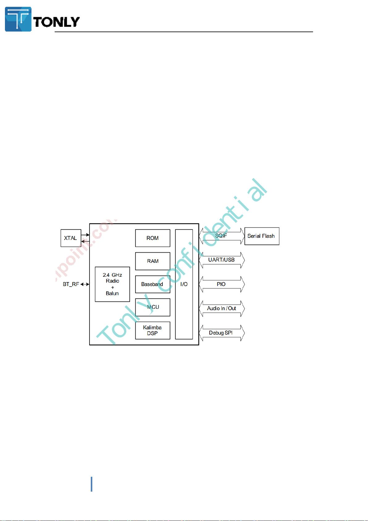
The QCC3007 module is a single-chip flash programmable dual mode Bluetooth v5.0 device with
integrated application processor, low-power audio DSP, on-chip ROM and RAM, stereo codec,
battery charger, switch-mode and linearregulators, and LED drivers.
1.2 性能特点 Features
Bluetooth ® v5.0 specification compliant
Multipoint support for A2DP connection to 2A2DP sources for music playback
Stereo line-in
True Wireless Stereo (TWS)
Low Power Consumption
Supported Bluetooth Profiles:A2DP v1.3.1 , AVRCP v1.6,HFP v1.7, GAIA, EQs.
1.3 系统方框图Block Diagram
2.产品描述 Production Description
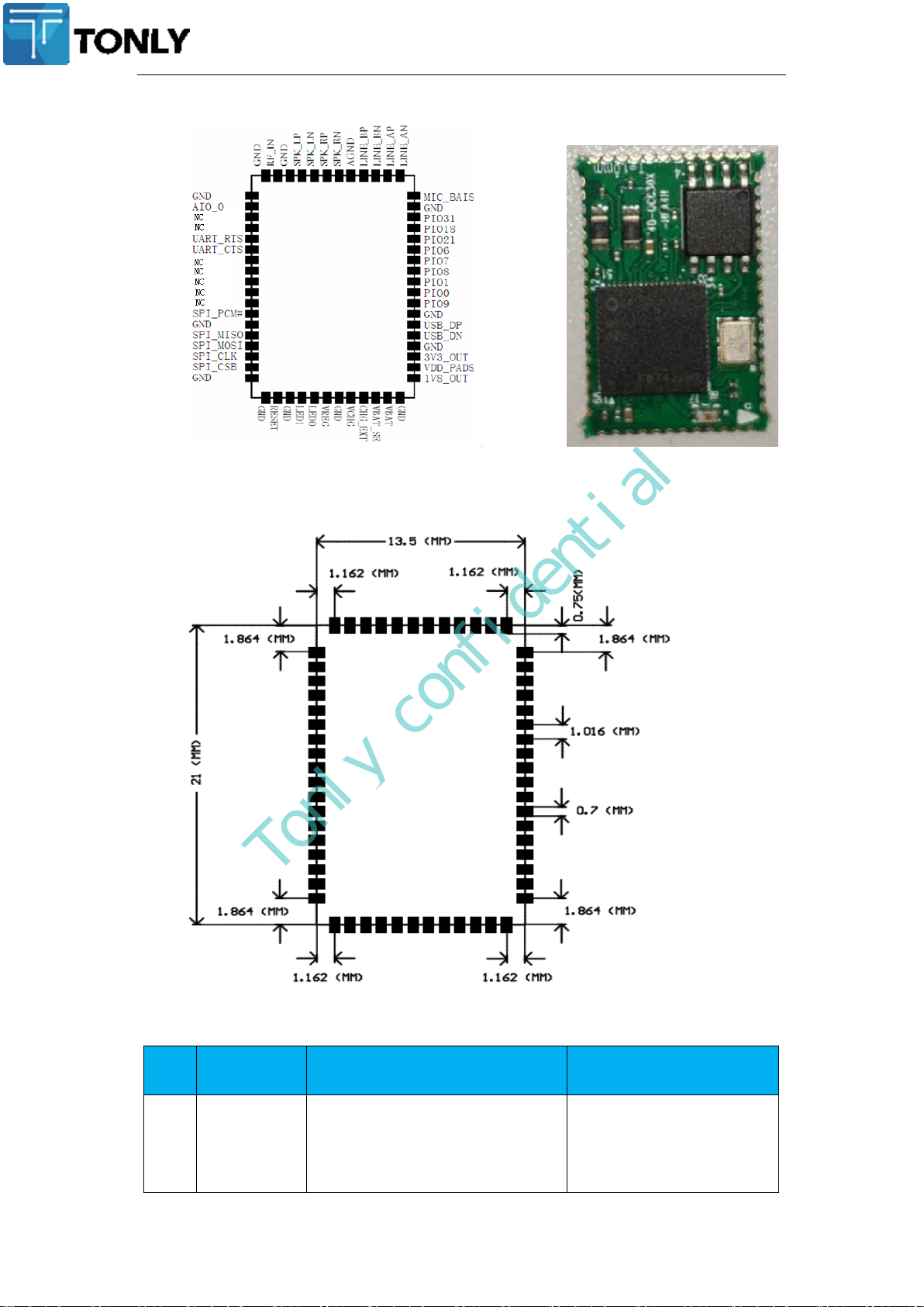
引脚与功能说明 Apperance & Pin Description&
Physical Dimensions
Description & Apperance:
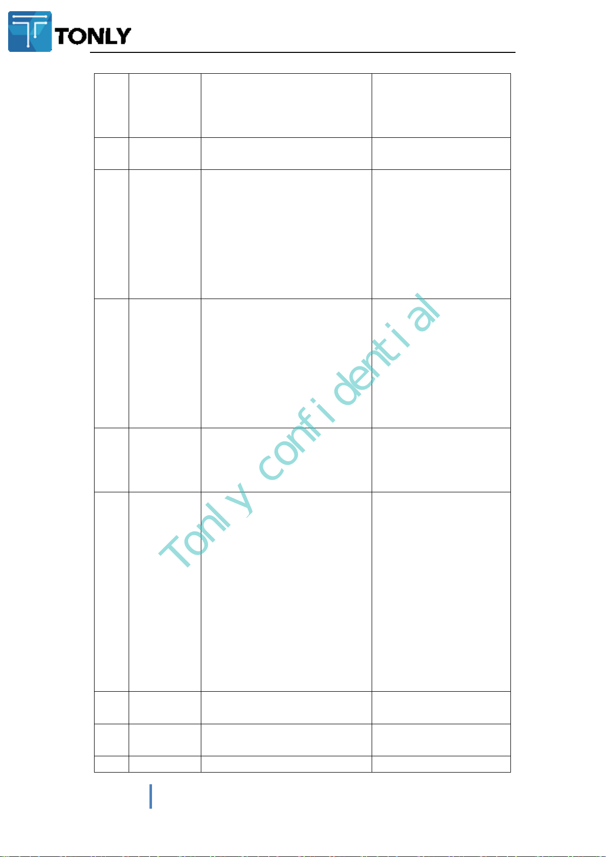
Page 6
PIN
NO.
Symbol
Description
Function
1、18、
19 、
21 、
25 、
GND
Power supply and control
Ground connections.
Tonly confidential
Physical Dimensions
Pin descriptions
Page 7
TBM-QCC307B Bluetooth Module Datasheet
7
TONLY ELECTRONICS HOLDINGS LIMITED Confidential
30 、
33 、
37 、
47、58
2
AIO0
Bi-directional with programmable
analog I/O.
Analogue Programmable I/O
5
UART_RTS
A CMOS output with a weak
internal pull-up. This pin can be
used to implement RS232
hardware flow control where RTS
(request to send) is an active low
indicator. The UART interface
requires an external RS232
transceiver chip.
UART request to send, active
low
Alternative function:
PIO16: Programmable input /
output line 16.
Bidirectional with strong
pull-up
6
UART_CTS
A CMOS input with a weak
internal pull-down. This pin can
be used to implement RS232
hardware flow control where CTS
(clear to send) is an active low
indicator. The UART interface
requires an external RS232
transceiver chip.
UART clear to send, active
low;
Alternative function:
PIO17: Programmable input /
output line 17.Bidirectional
with strong pull-down.
Bidirectional with strong
pull-down
3、4、
7、8、
9、10、
11
NC
Leave unconnected
NC
12
SPI_PCM#
Configurated PCM/I2S digital audio
interfa-
ce shares the same physical
set of pins with the SPI interface.
SPI_PCM# is a CMOS input with a
weak internal pull-down. When
inputs HIGH level, this set of pins is
used
For SPI interface. When inputs
LOW level, this set of pins is used
for PCM/PIO/I2S interface.
SPI/PCM select input:
0 = PCM/PIO interface
1 = SPI
14
SPI_MISO
Programmable I/O line or debug SPI
MISO selected by SPI_PIO#.
SPI data output
15
SPI_MOSI
Programmable I/O line or debug SPI
MOSI selected by SPI_PIO#.
SPI data output
16
SPI_CLK
Programmable I/O line or debug SPI
SPI CLOCK
Tonly confidential
Page 8

CLK selected by SPI_PIO#.
17
SPI_CSB
Programmable I/O line or debug SPI
chip select (CSB) selected by
SPI_PIO#.
chip select for SPI, active low
20
RESET
The RESET pin is an active high reset
and is internally filter educing the
internal low frequency clock
oscillator .A reset will be performed
between1.5 and 4.0ms following
RESET being active.
Reset if low. Pull low for
minimum 5ms to cause a
reset.
22
LED_1
Bidirectional
Programmable Input/Output
Line & LED driver
23
LED_0
Bidirectional
Programmable Input/Output
Line & LED driver
24
POWER_VRE
G
Enable pin for the internal 1.8V
regulator, This pin is only available
with production version
Regulator enable input.
Can also be sensed as an
input.
Regulator enable and
multifunction button. A high
input (tolerant to VBAT)
enables the on-chip
regulators, which can then be
latched on internally and the
button used as a
multifunction input.
26
VBUS
Power supply and control
Charger input.
Typically connected to VBUS
(USB supply)
27
CHG_EXT
Power supply and control
External battery charger
control.
External battery charger
transistor base control when
using external charger boost.
Otherwise leave
unconnected.
28
VBAT_SENSE
Power supply and control
Battery charger sense input.
Connect directly to the
battery positive pin.
29
VBAT
Input for an internal 1.8V
switched mode regulator
combined with output of the
internal battery charger.
Battery charger input
Tonly confidential
Page 9

TBM-QCC307B Bluetooth Module Datasheet
9
TONLY ELECTRONICS HOLDINGS LIMITED Confidential
31
1.8V_OUT
Power supply and control
1.8V DC/DC convertor
output.
32
VDD_IO
Power supply and control
Positive supply input for
input/output ports.
33
3V3_OUT
Power supply and control
3.3V bypass linear regulator
output.
Also supply for USB port.
35
USB_DN
Abi-directional USB data line
with a selectable internal
1.5kΩ pull-up implemented
as a current source (compliant
with USB specification v2.0)
An external series resistor is
required to match the
connection to the
characteristic impedance of
the USB cable.
USB data minus.
36
USB_PN
A bi-directional USB data line. An
external series resistor is required to
match the connection to the
characteristic impedance of the USB
cable.
USB data plus with selectable
internal 1.5kΩ pull-up
resistor.
38
PIO_9
programmable analog I/O.
Programmable I/O.
39
PIO_0
programmable analog I/O.
Programmable I/O.
40
PIO_1
programmable analog I/O.
Programmable I/O.
41
PIO_8
programmable analog I/O.
Programmable I/O.
42
PIO_7
programmable analog I/O.
Programmable I/O.
43
PIO_6
programmable analog I/O.
Programmable I/O.
44
PIO_21
programmable analog I/O.
Programmable I/O.
45
PIO_18
programmable analog I/O.
Programmable I/O.
46
LED_2
Bidirectional
Programmable input /
output line & LED driver.
48
BIAS
Microphone bias
Microphone bias
49
LINE_AN
Analogue in
Line or microphone input
negative, channel A
50
LINE_AP
Line or microphone input
positive, channel A
51
LINE_BN
Analogue in
Line or microphone input
negative, channel B
52
LINE_BP
Line or microphone input
positive, channel B
Tonly confidential
Page 10

53
AGND
Connect Analog Ground pins
Analogue Ground
connections.
54
SPK_RN
Analogue out
Speaker output negative,
right
55
SPK_RP
Speaker output positive,
right
56
SPK_LN
Analogue out
Speaker output negative, left
57
SPK_LP
Speaker output positive, left
59
RF
This pin can be used when not using
a chip antenna or connector of the
module.
Bluetooth 50Ω transmitter
output /
receiver input
ELECTRICAL CHARACTERISTICS
Supply Voltage
1.8 – 3.6V DC
(Absolute Maximum Ratings1.8-4.2V)
Working current
Depends on profiles, 13mA (A2DP)
Standby current(disconnected)
1.05mA~3.1mA
WEIGHT AND DIMENSIONS
(unit : mm)
Size (L x W x H)
21*13.5*1.5 mm
Weight
0.9g
Min
Max Unit
Operating temperature
-
40
85 °C
VDD_IO
1.7 3.6 V
VDD_BAT
2.8 4.4 V
VDD_CHG
0 5.5 V
Terminal voltages
0 VDD V
Item
Min
Type
Max
Unit
Tonly confidential
3.应用说明 Application Explanations
Bluetooth stereo speakers
Speakerphones
4. 电气特性 Electrical Characteristics
Base Characteristics
Recommended operating conditions
电池充电 Battery charger
Page 11

TBM-QCC307B Bluetooth Module Datasheet
11
TONLY ELECTRONICS HOLDINGS LIMITED Confidential
Input Voltage
4.5
5
5.75
V
Charge Current(CC mode)
194
200
206
mA
Trickle Charge Current
10
mA
Trickle Charge Threshold Voltage
2.92
V
Regulated Output(Float)Voltage
4.2 V
Stereo CODEC Analogue to Digital Converter
Parameter
Conditions
Min
Typ
Max
Unit
Resolution
- - 16
Bits
Input Sample Rate,
8
-
48 kHz
Signal to Noise
Ratio, SNR
fin=1kHz
B/W=20Hz→20kHz
A-Weighted
THD+N<0.1%
1.6Vpk-pkinput
F
sample
8kHz
- 95.3 - dB
16kHz
- 93.8 - dB
32kHz
- 94.2 - dB
44.1kHz
-
92.4
-
dB
44.1kHz
-
91.8
-
dB
Digital Gain
Digital Gain Resolution=1/32
-24 -
21.5 dB
Analogue Gain
Analogue Gain Resolution=3dB
-3 - 42 dB
Maximum ADC Input
13 2260 - mVrms
3dBBandwidth
- 20 -
kHz
Stereo CODEC Digital to Analog Converter
Parameter
Conditions
Min
Typ
Max
Unit
Resolution
- - 16
Bits
Input Sample
Rate,F
sample
8
-
96
kHz
Signal to Noise
Ratio, SNR
fin=1kHz
B/W=20Hz→20kHz
A-Weighted
THD+N<1%
0dBFS
input
48KHz
Load=100K
-
95.6
-
dB
Digital Gain
Digital Gain Resolution=1/32
-24
- 21.5 dB
Analogue Gain
Analogue Gain Resolution=3dB
-
0
dB
Output voltage full scale swing(differential)
- -
778
mVrms
THD+N100kΩ load
- -
0.003
%
THD+N16Ω load
- - 0.0032 %
Specification
Description
RF performance
Standard
Bluetooth 5.0
Tonly confidential
5.射频性能 RF Performance
Page 12

Frequency Band
2.402~ 2.48GHz
Modulation Method
GFSK;4/ΠDQPSK;8DQPSK
Maximum Data Rate
1 Mbps/2 Mbps/3 Mbps
Antenna
External antenna
Interface
UART, PIO, AIO, SPI,PCM,SPI
Operation Range
>=10 meters(Free Space)
Sensitivity
-86dBm at 0.1% BER
RF TX Power
<=+10dBm
Tonly confidential
6.认证与法规信息 Certification& Regulation
The BQB Certification:
FCC
This device complies with Part 15 of the FCC Rules. Operation is subject to the following two
conditions :
(1) this device may not cause harmful interference, and
(2) this device must accept any interference received, including interference that may cause
undesired operation.
7.包装与订货说明 Package & Ordering Information
Assembly
60Pcs per every Blister tray
600Pcs per every Vacuum packing
Page 13

TBM-QCC307B Bluetooth Module Datasheet
13
TONLY ELECTRONICS HOLDINGS LIMITED Confidential
Tonly confidential
8.环保声明 Green Policy
This module can meet ROHS&REACH compliance.XXXX
9.推荐过炉温度 RECOMMENDED TEMPERATURE REFLOW PROFILE
The soldering profile depends on various parameters necessitating a set up for each
application. The data here is given only for guidance on solder re-flow. There are four zones:
1. Preheat Zone - This zone raises the temperature at a controlled rate, typically 1-2.5°C/s.
2. Equilibrium Zone - This zone brings the board to a uniform temperature and also activates the
flux. The duration in this zone (typically 2-3 minutes) will need to be adjusted to optimize the out
gassing of the flux.
3. Reflow Zone - The peak temperature should be high enough to achieve good wetting but not
so high as to cause component discoloration or damage. Excessive soldering time can lead to
inter metallic growth which can result in a brittle joint.
4. Cooling Zone - The cooling rate should be fast, to keep the solder grains small which will give a
longer lasting joint. Typical rates will be 2-5°C/s.
Page 14

Tonly confidential
Key features of the profile:
■ Initial ramp = 1-2.5°C/sec to 175°C ±25°C equilibrium
■ Equilibrium time = 60 to 180 seconds
■ Ramp to maximum temperature (245°C) = 3°C/sec max.
■ Time above liquidus temperature (217°C): 45-90 seconds
■ Device absolute maximum reflow temperature: 260°C
10.抗静电保护 ESD Protection
-------------------------END--------------------------
Page 15

For FCC:
Warning: Changes or modifications to this unit not expressly approved by the party
responsible for compliance could void the user’s authority to operate the equipment.
NOTE: This equipment has been tested and found to comply with the limits for a Class B
digital device, pursuant to Part 15 of the FCC Rules. These limits are designed to provide
reasonable protection against harmful interference in a residential installation. This
equipment generates, uses and can radiate radio frequency energy and, if not installed and
used in accordance with the instructions, may cause harmful interference to radio
communications.
However, there is no guarantee that interference will not occur in a particular installation. If
this equipment does cause harmful interference to radio or television reception, which can be
determined by turning the equipment off and on, the user is encouraged to try to correct the
interference by one or more of the following measures:
Reorient or relocate the receiving antenna.
Increase the separation between the equipment and receiver.
Connect the equipment into an outlet on a circuit different from that to which
the receiver is connected.
Consult the dealer or an experienced radio/TV technician for help.
“The device must not be co-located or operating in conjunction with any other
antenna or transmitter.”
FCC RF Radiation Exposure Statement Caution: To maintain compliance with the
FCC’s RF exposure guidelines, place the product at least 20cm from nearby persons.
The Module can be installed in Mobile or fix device only, and it can not be installed in any
portable Device.
FCC Conditions
This device complies with part 15 of the FCC Rules. Operation is subject to the following two
conditions:
1.This device may not cause harmful interference.
2.This device must accept any interference received, including interference that may cause
undesired operation.
This device complies with Part 15, Part 15.247 of the FCC Rules. The FCC ID for this device
is ZVAMS000026.
If the FCC ID is not visible with the module is installed inside another device, then it must be
still responsible for the FCC compliance requirement of the end product which referring to the
enclosed module and it also must display a label, such as the following:
Contains Transmitter module FCC ID: ZVAMS000026 or contains FCC ID: ZVAMS000026
The host product manufacturer is responsible for compliance to any other FCC rules that apply
to the host not covered by the modular transmitter grant of certification. The final host product
still requires Part 15 Subpart B compliance testing with the modular transmitter installed.
The end user manual shall include all required regulatory information / warning as shown in this
manual, include: This product must be installed and operated with a minimum distance of 20 cm
between the radiator and user body.
Page 16

The host Main unit is a SPHE8107H, It has 16Mb flash and needs
frequency. This chip is responsible to control
input
Host .For the FCC certification,
manufacturer adds a shield cover for the whole machine test, it needs to re-evaluate FCC spurious
emission test and make C2PC.
TBM-QCC307B
DSP, Bluetooth, audio system and all the source of
is without shielding cover test, If the Host
24.576MHz
crystal of reference
RF Traces for antennas
The figure below shows the general breakout of the module U2:
On U2 PCB board,
amplifier (PA) output and t
for emissions testing. The band-pass filter should be located as close to QCC3007 QFN as possible. The
grounding of the filter is critical to guarantee proper attenuation of the filter out of band. The layout
of the RF section in a QCC3007 QFN system can affect overall RF performance. Ground connections
become increasingly critical at RF frequencies. All ground pins should be connected to the main RF
reference ground plane On the QCC3007 QFN only two of the RF grounds are routed to lead frames,
the others are tied to the paddle underneath the die. See
Figure 1-1
A band-pass filter Fil1 needs to be inserted between QCC3007 power
he antenna.
This component can be added to provide additional margin
figure2-1
Page 17

Figure 2-1
For routing microstrip lines UNDERNEATH the NAD on layer 1, these ground cutouts internal
to the NAD need to be accounted for in the strip
For example, consider the following stackup for a U2 PCB:
line calculation.
Figure 3-1
Assume the U2 PCB Board above with a 4 layer stackup with ground cut away on layer 2 so
the microstrip lines reference ground on layer 3. The dielectric thickness from L1 to L3 is
Figure 3-1
Page 18

26.74mils. Using an online impedance calculator, the line width under the NAD for a 53 ohm line
is 16.87 mils .
Figure 3-2
Figure 3-2
We can put in tray like for U2 SMD to 40-TMAX50-VFD2G.
on
40-TMAX50-VFD2G
to match an impedance of 50 ohm at 2.45 GHz.
is a Inverted F Antenna (IFA).( See Figure4-1) The IFA was designed
Antenna Gain :3.0dBi.
The PCB antenna on the design
The antenna
could require a matching network, It use the LC Circuit. R16 3.3nH C15 0.2Pf. See Figure4-
2,4-3
Figure4-1
Page 19

Figure 4-2
Figure 4-3
This 50ohm line(yellow)should be as short as possible to the IFA or
Page 20

internal antenna feed point.
See Figure 5-1
Figure 5-1
Mechanical Specifications of the Antenna.
See Figure 6-1, Figure 6-2
Figure 6-1
H1 5.9mm H8 1.8mm L6 1mm
H2 0.9mm H9 1.2mm L7 3.2mm
H3 1.3mm L1 23.2mm L8 0.45mm
H4 2.2mm L2 14mm W1 1.2mm
H5 0.65mm L3 3.6mm W2 0.45mm
H6 1.2mm L4 3.37mm
H7 0.8mm L5 1mm
Page 21

Electrical
Antenna
Specifications of the Antenna
S11 Parameter See Figure 7-1 7-2
Figure 6-2
Figure 7-1
Gain and efficiency
Frequence/MHz 2402 2441 2480
Gain/dBi -0.114 0.4898 3.01
Efficiency/% 44.25% 45.92% 58.16%
Figure 7-2
RF Antenna Layout Parameters
• Signals should be routed along similar route path, but separated by ground trace.
• Trace impedances should match the table, either as microstrip or stripline.
• Total length for both signals should match the table.
• Spacing to ground or other signals on outside of bundled signals should match the table.
 Loading...