

Page 1

TCL Home Appliances (HeFei) Co., Ltd.
Refrigerator Disassembly and
Recycling Manual
Product model: TRF-436W
Page 2
Guidelines
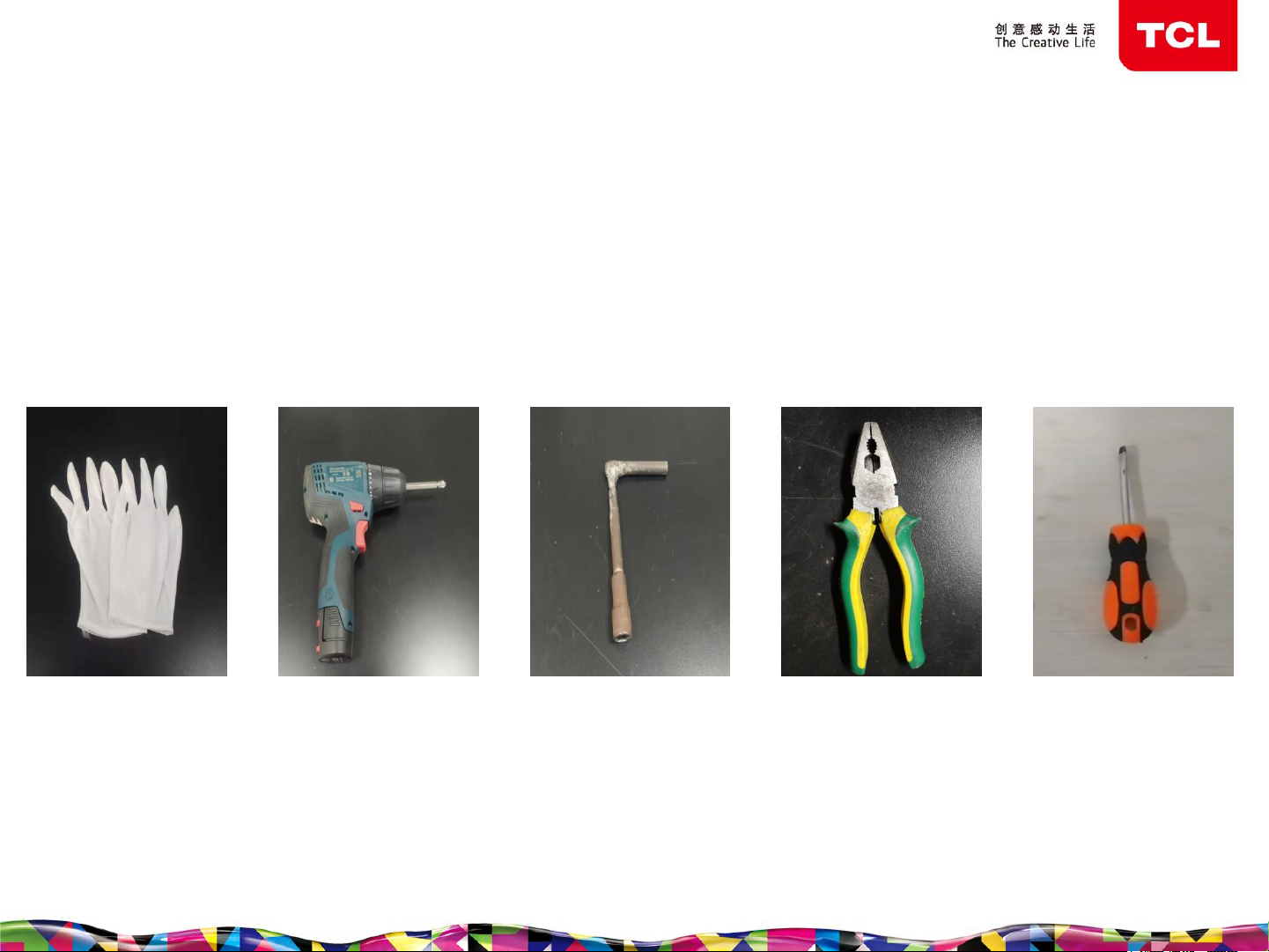
Required tools:
1. A pair of white gloves
2. A Phillips screwdriver
3. A sleeve (size: 8mm)
4. Pincer pliers
5. One flathead screwdriver
Disassembly Guide
A pair of white
gloves
A Phillips
screwdriver
(electric)
A sleeve
(size: 8mm)
2
Pincer pliers
One flathead
screwdriver
Page 3
Disassembly Guide
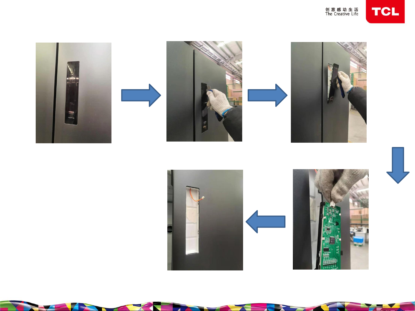
Guidelines for disassembly of display control board
1. Appearance of the
display control board
2. Insert the blade along
the edge of the display
control board
5. Complete the disassembly
of the display control board
3
3. Pry up the display
control board
forcefully
4. Unplug the connected
terminal
Page 4
Disassembly Guide
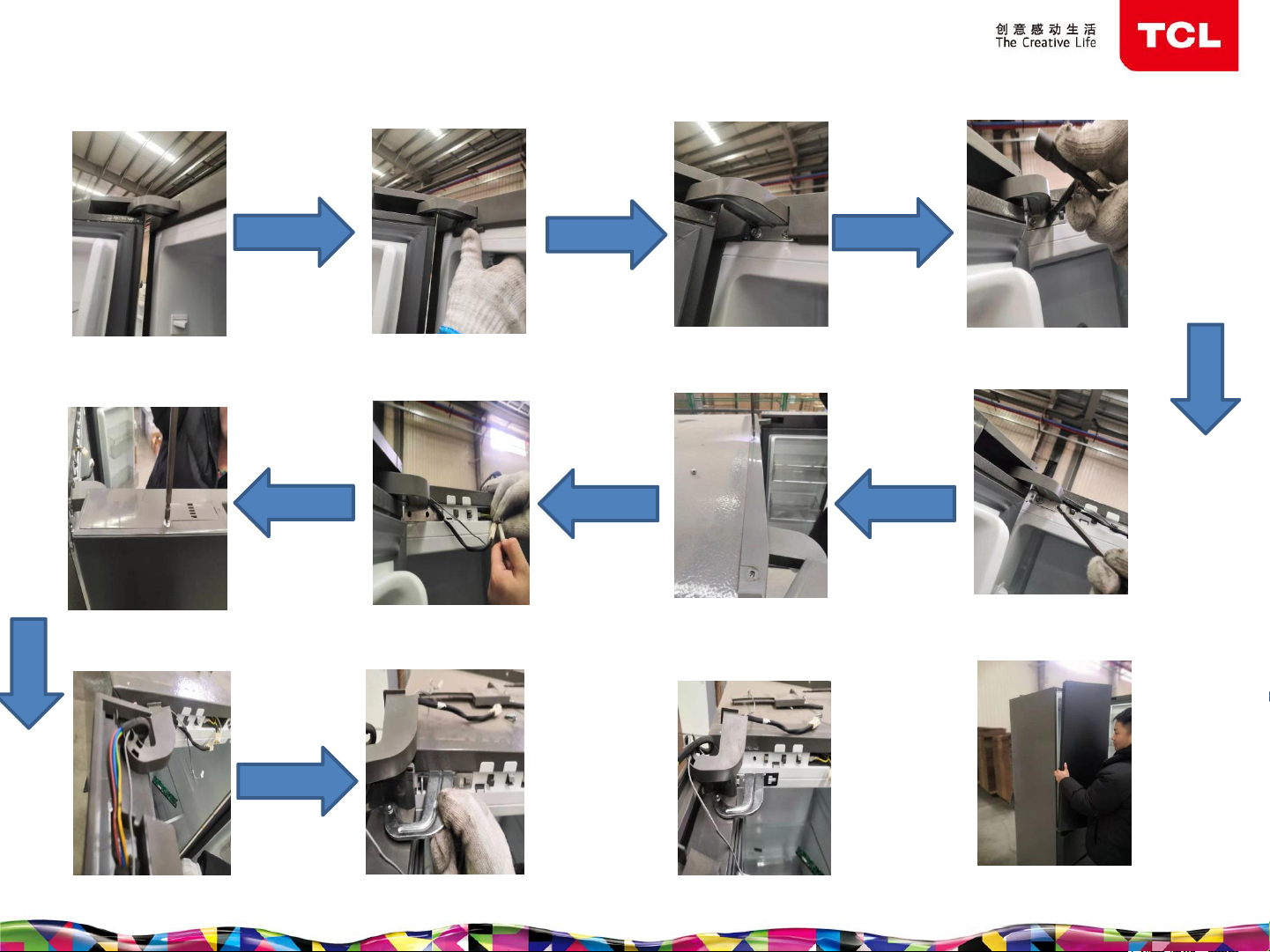
Guidelines for disassembly of the refrigerating chamber door (the same disassembly method for left
and right refrigerating chamber doors)
1. Appearance of upper hinge
8. Use a cross screwdriver
to remove the upper end
cover of the door
2. Push down the cover on the
hinge bolt forcefully to open
7. Unplug the wire harness
connection terminal
3. Remove the cover on
the upper hinge bolt
6. Use a cross screwdriver to
unscrew the screws of the
decorative cover and remove
the decorative cover
4. Use an 8mm sleeve to
loosen the two bolts of the
upper hinge
5. Use a cross screwdriver
to unscrew the two bolts of
the upper hinge
9. Grasp the upper hinge
cover and remove it forcefully
10. Remove the upper hinge
from the buckle
11. Complete the disassembly
of the upper hinge
4
12. Gently lift up and remove the
refrigerating chamber door to
complete the disassembly
Page 5
Disassembly Guide
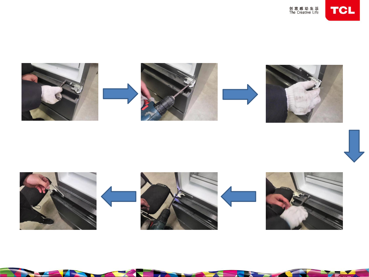
Disassembly of the middle hinge
1. Use an 8mm sleeve
to loosen the two bolts
of the right middle
hinge
6. Remove the left middle
hinge
2. Use a cross screwdriver to
unscrew the two bolts and one
screw of the right middle hinge
5. Use a cross screwdriver to
unscrew the two bolts and one
screw of the left middle hinge
5
3. Remove the right
middle hinge
4. Use an 8mm sleeve to
loosen the two bolts of the
left middle hinge
Page 6

Disassembly Guide
1. Pull out the variable
temperature chamber drawer
2. Grasp the drawer and lift it
up forcefully
chamber drawer
Disassembly of the variable temperature
3. Carefully take out the
variable temperature chamber
drawer
6
4. Complete the disassembly of the
variable temperature chamber
drawer
Page 7

Disassembly Guide
1. Pull out the freezer chamber
drawer
2. Grasp the drawer and lift it upwards forcefully,
carefully take out the freezer chamber drawer
Disassembly of the freezer chamber drawer
3. Complete the disassembly of the
freezer chamber drawer
7
Page 8

Disassembly Guide
Guidelines for disassembly of refrigerating chamber lamp assembly
1. Appearance of
refrigerating chamber
lamp assembly
2. Use a flathead screwdriver
to insert along the edge of the
lampshade and lift it up
forcefully
5. Complete the disassembly of
the refrigerating chamber lamp
assembly
8
3. Pull out the LED light
board from the inner liner
4. Unplug the wire harness
connection terminal
Page 9

Disassembly Guide
Guidelines for disassembly of refrigerating air duct
1. Appearance of
refrigerating air duct
6. Unplug the wire harness
connection terminal
2. Use a flathead screwdriver to
remove the screw cover at the
bottom of the air duct
5. Grasp the air duct assembly with
both hands, pull it outward and
remove it carefully
3. Use a cross screwdriver to
remove the screws at the
bottom of the air duct
4. Complete the
disassembly of screw
7. Complete the disassembly
of the refrigerating air duct
9
Page 10

Disassembly Guide
Disassembly of freezing air duct
1. Appearance of freezing air
duct assembly
2. Use a cross screwdriver to
remove the two screws on the left
and right of the air duct
5. Complete the disassembly of the
freezing air duct
10
3. Grasp the bottom edge of the
freezing air duct assembly by
hand, lift it up forcefully and
remove the freezing air duct
assembly
4. Unplug the connected
wire harness terminal
Page 11

Disassembly Guide
Disassembly of the main control board (note that the main control
board of model 436 is on the back of the box)
1. Appearance of the
main control board
cover
6. Complete the
disassembly of the main
control board
2. Use a cross
screwdriver to unscrew
the screws on the main
control board cover
5. Take out the main
control board
11
3. Lift and remove the
main control board cover
4. Unplug all the wire harness
terminals connected to the
main control board
Page 12

Disassembly Guide
Disassembly of the inverter
1. Appearance of the
inverter
6. Complete the
disassembly of the
inverter
2. Use a cross screwdriver to
unscrew the screws on the side
cover of the inverter and
remove the cover
5. Unplug the wire harness
terminal connecting the inverter
to the top of the compressor
compartment
12
3. Use a cross screwdriver
to unscrew the screws at
the bottom of the inverter
4. Unplug the wire harness
terminal connecting the
inverter and the
compressor
Page 13

Disassembly Guide
Disassembly of the bottom adjusting foot
1. Appearance of
bottom adjusting foot
6. Complete the
disassembly of the
bottom adjusting foot
2. Use an 8mm sleeve to
loosen the two bolts of
the lower hinge
5. Remove the bottom
adjusting foot by hand
13
3. Remove the bolts with a
cross screwdriver
4. Use a cross screwdriver to
remove the other bolt
Page 14

Disassembly Guide
Step I: Use a screwdriver to remove the
fixing screws of evaporator;
Step II: Use pincer pliers to cut off the
evaporator tube and remove the
evaporator;
Disassembly of the fin evaporator
14
Page 15

Disassembly Guide
Step I: Use pincer pliers to cut off all the high and low
pressure pipelines of the compressor chamber;
Disassembly of compressor chamber
Step II: Use an 8mm sleeve and a Phillips
screwdriver to loosen four fixing screws on the
bottom of the compressor, and then remove the
compressor floor;
15
Step III: Use an 8mm sleeve and a Phillips
screwdriver to remove fixing screws on the
bottom of the compressor, and finally
remove the compressor;
 Loading...