

Page 1

TCL
FLOOR-STANDING SPLIT-TYPE AIR CONDITIONERS
SERVICE MANUAL
No.20170622
Models
TFF-60HRA/TOF-60HSA
CONTENTS
1. IMPORTANT NOTICE
2. PRODUCT DIMENSIONS
3. REFRIGERATION CYCLE DIAGRAM
4. OPERATION DETAILS
5. WIRING DIAGRAM
6. EXPLOSION VIEW AND PART LISTS
Page 2

TCL Air Conditioner Service ManualTCL Air Conditioner Service ManualTCL Air Conditioner Service Manual
Air Conditioner Service Manual
2
IMPORTANT NOTICE
This service manual is intended for use by individuals possessing adequate
backgrounds of electrical, electronic and mechanical experience. Any
attempt to repair the appliance may result in personal injury and property
damage. The manufacturer or seller cannot be responsible for the
interpretation of this information, nor can it assume any liability in
connection with its use.
The information, specifications and parameter are subject to change due to
technical modification or improvement without any prior notice. The
accurate specifications are presented on the nameplate label.
How to order spare parts
To have your order filled promptly and correctly, please furnish the
following information:
1. Model No. with Indoor or Outdoor
2. No. in the Explosion View
3. Part Name
4. The quantity you ordered
Page 3

Air Conditioner Service Manual
2. PRODUCT DIMENSIONS
Indoor Unit:
Outdoor Unit:
Model A B C D E F G H I J K
60K 650 405 1920 940 1250 340 600 400 375 50 63
3
Page 4
Air Conditioner Service Manual
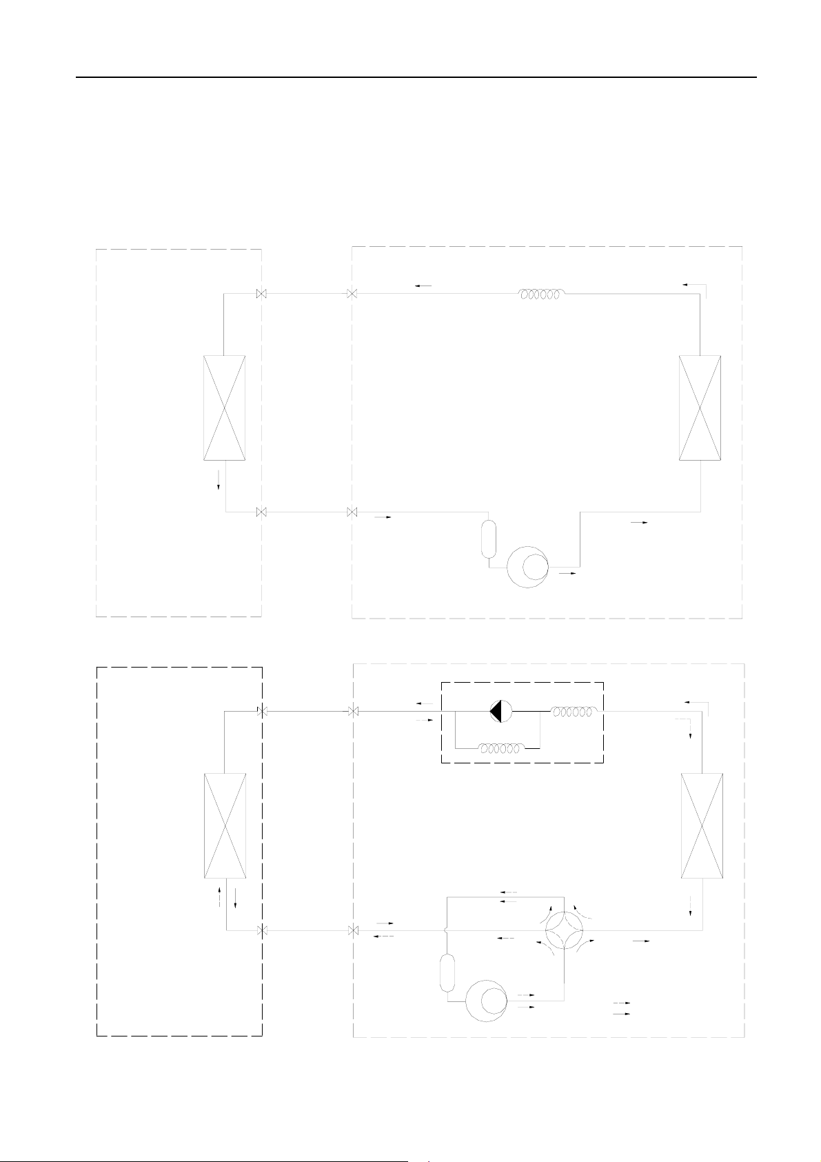
3. Refrigeration cycle diagram
Cooling only
Heat exchange
(Evaporator)
Heat pump
Heat exchange
(Evaporator)
Liquid side
2-way valve
Gas side
3-way valve
Accumulator
Liquid side
2-way valve
Gas side
3-way valve
Accumulator
Capillary
Compressor
Check valve
Capillary Assembly
4-way valve
Compressor
Heat exchange
(condenser)
Heat exchange
(condenser)
Heating
Cooling
3
Page 5
4.Operation Details
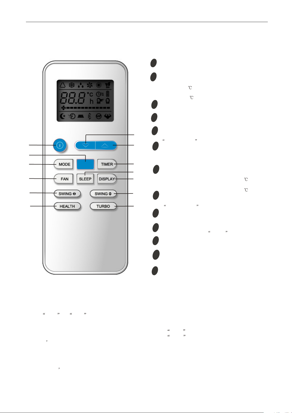
Remote controller
1
2
3
ECO
4
5
6
Air Conditioner Service Manual
ON/OFF button
1
To switch the conditioner on and off.
2
ECO button
In cooling mode,press this button ,the temperature
will increase 2 on the base of setting temperature:
In heating mode, press this button, the temperature
will decrease 2 on the base of setting temperature.
MODE button
3
To select the mode of operation.
FAN SPEED button
4
To select the fan speed of auto/low/mid/high.
SWING button
13
12
11
10
9
8
7
5
To activate or deactivate of the movement of the
DEFLECTORS .
6
HEALTH button
To switch - on /off HEALTHY funtion.
which controls the ionizer or plasma generator only
for inverter type.
TURBO button
7
In cooling mode, press this button, the unit will give
the maximum cooling temperature with 16
In heating mode, press this button, the unit will give
the maximum heating temperature with 31 .
8
SWING button
To activate or deactivate of the movement of the
DEFLECTORS .
DISPLAY button
9
To LED display (if present)switch on/off the
It is a button
SLEEP button
10
10
9
To activate the function SLEEP .
TIMER button
11
9
To set automatic switching-on/off.
12
TEMP UP button
Increase the temperature or time by 1 unit.
TEMP DOWN button
13
9
Decrease the temperature or time by 1 unit.
9
Note: Each mode and relevant function will be further specified in following pages.
Remote Control
The remote controller is not presetting as Cooling Only Air Conditioner or Heat Pump by manufacturer.
Each time after the remote controller replace batteries or is energized, the arrowhead will flashes on the
front of Heat or Cool on LCD of the remote controller.
User can preset the remote controller type depending on the air conditioner type you have purchased as
follows:
Press any button when the arrowhead flashes on the front of Cool , Cooling Only is set.
Press any button when the arrowhead flashes on the front of Heat , Heat Pump is set.
If you don t press any button within 10 seconds, the remote controller is preset as Heat Pump
automatically.
Note :
If the air conditioner you purchased is a Cooling Only one, but you preset the remote controller as Heat
Pump, it doesn t bring any matter. But if the air conditioner you purchased is a Heat Pump one, and you
preset the remote controller as Cooling Only, then you CAN NOT preset the Heating operation with the
remote controller.
4
Page 6
Air Conditioner Service Manual
Electronic Controller
1. Safety Control
(1) Time Delay Safety Control
z 3 minutes delay for compressor---The compressor is ceased for 3minutes to balance the pressure in the
refrigeration cycle in order to protect the compressor.
z 2 minutes delay for 4-way valve---The 4-way valve is ceased for 2 minutes to prevent the
refrigerant-gas abnormal noise when the HEATING operation is OFF or switch to the other operation
mode.
(2) Indoor Pipe Temperature Sensor Frost Prevention Control
When the indoor pipe temperature sensor reads 0℃ or below for 5 minutes, the indoor pipe temperature
sensor frost prevention control starts. The compressor and outdoor fan stop and indoor fan operates at high
speed for 3 minutes. After that, if the indoor pipe temperature sensor reads less than 5℃ this control
prolonged until the indoor pipe temperature sensor reads 5℃ or more.
(3) High Temperature Protection Control
During HEATING operation, the outdoor fan motor and compressor are controlled by the indoor pipe
temperature to prevent the high temperature of compressor.
Outdoor fan OFF: when the indoor pipe temperature is ≥53℃
Outdoor fan ON: when the indoor pipe temperature is ≤48℃
Compressor OFF: when the indoor pipe temperature is ≥62℃
Compressor ON: when the indoor pipe temperature is ≤48℃
2. “Feel” Mode Operation
(1) When the “I Feel” mode is selected, the operation mode and initial set temperature are determined by the
initial room temperature at start-up of the operation except to turn off the air conditioner and operates it
again.
(2) If the mode is change to “I Feel” mode from other mode, the “I Feel” mode doesn’t operate until compressor
stop for more than 3 minutes.
COOLING
DRY
HEATING for Heat Pump Type
FAN for Cooling Only Type
z In the “I Feel” mode , when the controller receives the up or down single of temperature, the set
3. “COOLING” Mode Operation
(1) When the COOLING mode is selected without setting temperature, the system will set the set temperature at
℃ automatically with the AUTO FAN speed.
26
(2) When selecting the COOLING mode operation, the system will operate according to the setting by the
remote controller and the operation is as following:
Mode
temperature can adjust by 1
Initial room temperature
26℃ or more
20℃ to 25 ℃
Less than 20℃
Initial set temperature
24℃
18℃
23℃
℃ upper or lower. The biggest you can adjust by 2℃ upper or lower.
5
Page 7

Air Conditioner Service Manual
Room Temp.
Set TEMP. +1℃
Set TEMP. -1℃
Time
More than 2 min
More than 2 min
More than 2 min
More than 2 min
More than 2 min
Indoor Fan
Set Speed
Set Speed
Set Speed
Set Speed
Set Speed
Compressor
ON
OFF
ON
OFF
ON
Outdoor Fan
ON
OFF
ON
OFF
ON
Set Temp. +1℃
Set Temp. -1℃
Room Temp.
Time
More than 2 min
More than 2 min
More than 2 min
More than 2 min
More than 2 min
Compressor
ON
OFF
ON
OFF
ON
Outdoor fan
ON
OFF
ON
OFF
ON
Temperature raise
Temperature drop
4. “DRY” Mode Operation
(1) The system for DRY operation used the same refrigerant circle as the cooling circle.
(2) When the system operates in DRY mode ,at first it operates in cooling mode at 16℃ or 18℃ for 3 minutes.
And then, the system operates in cooling mode with low speed that regards the temperature of the room
temperature sensor reads decrease 2℃ as the set temperature. During the course of this, the fan speed
set operation is failing but the vane motor can be controlled.
5. “HEATING” Mode Operation (Only available for Heat Pump)
(1) When the HEATING mode is selected without setting temperature, the system will set the temperature at
23℃ automatically with the AUTO FAN speed.
(2) When selecting the HEATING mode operation, the system will operate according to the setting by the
remote controller and the operation is as following:
(3) In HEATING mode, the indoor fan motor speed is controlled by Cold Air Prevention Control.
(4) Cold Air Prevention Control
The function is intend to prevent cold air from being discharged when the heating operation starts or
when defrosting.
The indoor fan speed will be controlled as following.
The vane angle is at the angle C(100°).
Set Speed Set Speed
34℃
Low Speed
27℃
Low Speed
25℃
Stop the fan
23℃
Stop the fan
During the heating operation, if the compressor stops that it will adjust the indoor fan speed, after 30
seconds to stop the fan.
6
Page 8
Air Conditioner Service Manual
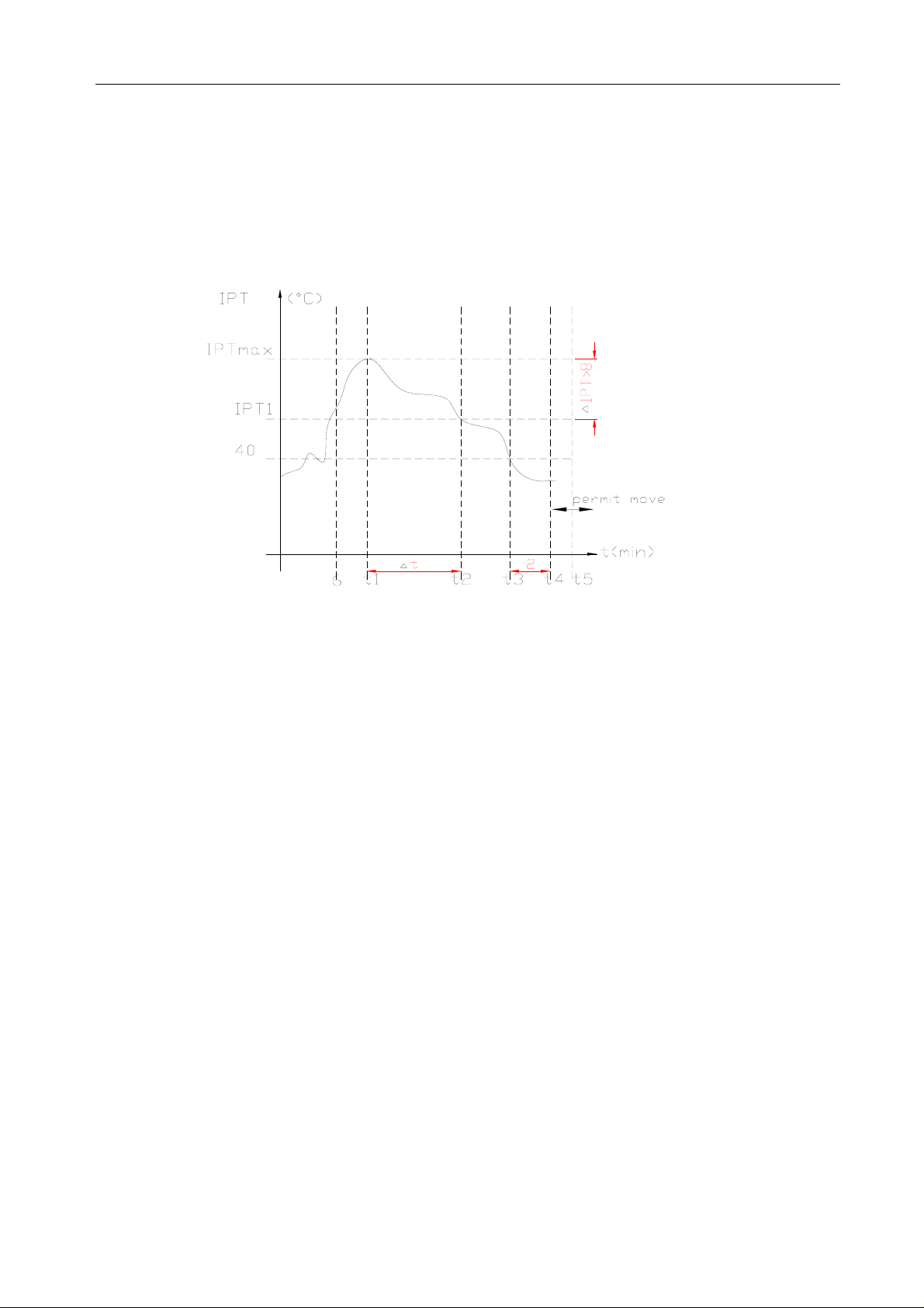
(5) Defrost
Defrosting of the outdoor heat exchange is controlled by the microprocessor with detection by the indoor
pipe temperature sensor.
Defrost control type is according to the JC on the PCB whether is connected.
z When the JC is connect on the PCB
When one of the conditions of A, Band C is satisfy, the defrosting operation stars.
A. IPT--- indoor pipe temperature
In the condition A, it must satisfy the conditions a), b)and c) then into defrosting operation.
a) IPT1 satisfy IPT1=IPT
b) t5≥50minutes(the compressor cumulative operation time≥50 minutes, t5 is permitted move
and lower than t1 too).
IPT<40℃,and keep 2 minutes.
c)
According to the condition A enter the defrosting operation, the first defrosting operation time is
8minutes; After defrosting operation one cycle, and then judge and regulate the defrosting operation
time.
B. After the compressor cumulative operation time exceeds 120 minutes and the temperature of the IPT
is less then 35
℃ for 2 minutes. When the defrosting operation time on this condition exceeds
-△IPT(8℃)
MAX
8minutes, it will terminate.
C. After the compressor operation continuously for 20 minutes and the IPT is less than 23℃ or from
the last time of defrosting operation is 50 minutes or more interval. When the defrosting operation
time on this condition exceeds 10 minutes, it will terminal.
z When the JC isn’t connected on the PCB
When the conditions of a) or b) is satisfy, the defrosting operation starts.
a) Have the outdoor sensor on the outdoor unit: Under the heating operation, the compressor cumulative
operation time exceeds 50 minutes and the temperature of the outdoor pipe temperature sensor reads
lower than -4
b) No the outdoor on the outdoor unit: Under the heating operation, the compressor cumulative
operation time exceeds 50 minutes, if the indoor pipe temperature sensor reads lower than 40
℃.
℃
continuously for 2minutes.
z Defrost terminating conditions
When the condition c) or d) is satisfy, the defrosting operation will terminal.
c) The outdoor defrost sensor reads 15
℃ or more.
d) The defrosting time exceeds 10 minutes.
7
Page 9
Air Conditioner Service Manual
Defrosting time chart
Outdoor Fan ON OFF ON
Revering Valve ON OFF ON
Compressor Relay ON OFF ON OFF ON
39S 5S Defrost Count MAX 12min 19S 15S t
6. “FAN” mode operation
The indoor fan motor always turns on at the set speed and the vane motor turns on at the set fettle.
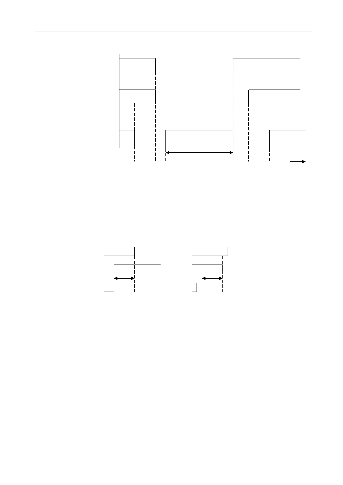
7. 4-way Valve control
HEATING ON
COOLING/DRY OFF
The 4-way valve reverses for 5 seconds right before start-up of the compressor as following chart:
COOLING/DRY TO HEATING HEATING TO COOLING/DRY
Compressor
4-way Valve
5s 2min
Outdoor Fan
8. Assistant Heater
1) The heater mode is automatically controlled.
2) The condition of the heater ON. (must accord with the following conditions)
a. The compressor has operated over 10 minutes.
b. The indoor fan motor has operated at normal over 15 minutes.
c. Not at the defrosting.
d. The heater latest off was over 30 seconds.
e. ST-RT≥3℃。
f. RT<22℃.
g. IPT≤43℃
3) The condition of the heater OFF. (accord with one of the following condition)
a. The compressor off.
b. RT≥24℃.
c. IPT≥48℃
d. Indoor motor off.
e. Enter the sleep mode.
9. “SLEEP” mode
When the SLEEP button is pressed, the SLEEP mode is selected as following:
8
Page 10

Air Conditioner Service Manual
motor is shut off. 10 seconds later, the electric current is applied to the fan motor again. During the fan motor
lock-up, the POWER indicator lamp flashes on and off 6times/cycle or E6 to show the fan motor
abnormality.
10. Auto Fan Speed Control
(1) When the auto fan speed is selected, the indoor fan motor speed is automatically controlled by the room
temperature and the set temperature.
(2) In COOLING mode, the indoor fan motor operates as following:
Fan Speed
Hi
Me
Lo
Room temperature minus set temperature: 1℃ 2℃ 4℃
(3) In HEATING mode, the indoor fan motor operates as following;
Fan Speed
Hi
Mi
Lo
Room temperature minus set temperature 1
℃ 2℃ 4℃
11. Auto V ane Operation control
(1) Vane motor drive
The unit is equipped with a stepping motor for the vane. The rotating direction, speed, and angle of the
motor are controlled by pulse signal transmitted from indoor microprocessor.
(2) Positioning
The vane is once pressed to the vane stopper below to confirm the standard position and then set to the
desired angle. The positioning is decided as follows:
z When the ON/OFF button is pressed.
z When the vane control is change from AUTO to MANUAL.
z When the SWING is finished.
z When the test run starts.
z When the power supply turns ON.
(3) The auto vane changes as follows by pressing the VANE CONTROL button.
(4) VANE AUTO mode
In vane auto mode, the microprocessor automatically determines the vane angle and operation to make the
optimum room-temperature distribution.
(5) SWING mode
When presses the SWING button, the vane swings.
12. TIMER Operation
(1) To activate the air conditioner at the desire time, follow the procedure specified below(the remote control
and air conditioner are switched off):
z Press the Timer button.
z Select the desired mode by pressing the Mode button.
z Select the desired temperature by pressing the ▲ ▼ button(only possible when the ‘cool’ or ‘heat’
mode is selected).
z Select the ventilator speed (low, medium or high) or automatic mode(only possible when the feel, Cool
or Heat mode is selected) by pressing the Fan button.
The ventilator always operates in the Auto mode when the Dry mode is selected.
z Select Swing or no Swing by pressing the Swing button.
9
Page 11

Air Conditioner Service Manual
z Press the Timer button(‘h’ flashes).
z Use the ▲▼ button to select the time at which the air conditioner must activate (between 0 and 10
hours can be set at every half hour-between 10 and 24 hours can be set at every hour).
z Press the Timer button (‘h’ stops flashing) and the preset time appears in the display.
z Press the Timer button again to delete the selected data from the memory.
Note : If no buttons are pressed during the programming of the timer function, thee remote control will
switch off automatically after 10 seconds.
(2) To switch the air conditioner off at the desired time, follow the procedure specified below (the remote control
and air conditioner are switched off):
z Press the timer button.
z Use the ▲▼ button to select the time at witch.
13. EMERGENCY Operation
When the EMERGENCY Operation switch is pressed once, COOLING mode is selected and if in 3 seconds the
EMERGENCY Operation switch is pressed again, mode is selected. Then pressed once again, the unit is switch
off.
When the remote controller is missing, has failed or the batteries run down, press the EMERGENCY Operation
switch on the front of the indoor unit. The unit will start.
The first 30 minutes of operation will be the test run operation. The operation is for servicing. The indoor fan runs
at high speed and the system is in continuous operation. The thermostat is ON and the timer is reset to normal.
After 30 minutes of test run operation the system shifts to AUTO COOLING/HEATING mode, and the indoor fan
runs in automatic speed. The operation continues unit the EMERGENCY operation switch is pressed or a button
on the remote controller is pressed, the normal operation will start.
NOTE: Do not press the EMERGEMCY Operation switch during normal operation.
14. AUTO RESTART Function(Option)
1.When the indoor unit is controlled with the remote controller, the operation mode, set temperature, and the fan
speed are memorized by the indoor electric control PCB. The AUTO RESTART function sets to work the
moment power has restored after power failure. Then, the unit will restart automatically.
2. How to set the AUTO RESTAR function.
z Press the emergency switch and power supply to the PCB following, keep 10seconds and the buzzer will
beep three times. The AUTO-RESTAR is set.
z Do the operation again, the buzzer will beep four times and the AUTO-RESTAR function is cancelled.
15. Electron Lock Function:
Press the fan button for 5 seconds, the buzzer beep one sound. The all button is invalidation for operate the air
conditioner except the remote controller.
16. Failure Display and Handling
a) Failure Display
When the controller is failure, the buzzer will voice long for three times, and displays the failure from the
failure lamp.
b) Failure Code
If have the digital pipe that display the failure code for digital pipe, or display for the run lamp.
Type of failure The lamp flash Display of digital pipe
The failure of room temperature sensor E1
The failure of indoor pipe temperature sensor E2
Outdoor unit protected E5
c) Failure Handling
z When the room temperature sensor or the indoor pipe temperature sensor is failure, the system will be
shut off, the compressor will be OFF, and the outdoor fan and the indoor fan will be OFF. The system
10
Page 12

Air Conditioner Service Manual
doesn’t receive the signal of remoter controller except the signal of shut off it. When the failure
disappear, the controller can operate in normal mode. before this, presses the “ON/OFF” to start the
system, and it will operate in COOLING or HEATING for 30 minutes, and follows shut off. During
this, it displays the failure and the protection is failing. You must be given the electric again to operate
it. In the failure, you can operate the FAN mode.
z When the outdoor protects in the COOLING or DRY, the outdoor unit stops, the indoor fan operates in
set speed ; and in the HEATING, the outdoor unit stops, the indoor fan operates in cold air prevention
control. The system doesn’t receive the signal of remoter controller except the signal of shut off it.
When the system check the voltage is 220V and the delay control is finished, it operates at normal
again.
z When the indoor fan motor is failure, the compressor is stopped, the outdoor fan and indoor fan is
stopped and display the failure. The system doesn’t receive the signal of remoter controller except the
signal of shut off it.
d) Display Of The Control
In the display board the lamp from left is the POWER lamp(Red), the SLEEP lamp(Yellow), the TIMER
lamp(Yellow), the RUN lamp(Green).
g) When gives the control electric, the buzzer voices a long for 0.3 second per cycle.
11
Page 13

Air Conditioner Service Manual
FM
~
5. WIRING DIAGRAM
MODEL: TFF-60HRA/TOF-60HSA
INDOOR UNIT:
OUTDOOR UNIT
12
Page 14

Air Conditioner Service Manual
1
2
3
4
5
6
7
8
9
19
18
17
20
21
10
11
12
13
14
15
16
22
2324
25
28
27
26
30
31
32
33
34
35
36
37
38
29
6. EXPLOSION VIEW AND PARTS
EXPLOSION VIEW
Mode: TFF-60HRA
INDOOR UNIT:
13
Page 15

Air Conditioner Service Manual
Part Name
Q’ty
Remark
1
210736221
Inside Base
1
2 230800121
Right Plate
1
3 230800122
Back Plate
1
4 230800120
Left Plate
1
5 211200107
Evaporator
1
6 230800124
Top Plate
1
7 210702134
Pipe Cover
1
8 230800123
Heat insulation board
1
9 1204090101
Rubber Water Drainage
1
10
210701012
Water Drainage
1
11
210800178
Inside Electrical Box
1
12
210901228A
Main PCB
1
13
1170200058
Terminal
1
14
230901276
Fan Motor Capacitor
1
15
1170240021
Transformer
1
16
1080520218
Inside Electrical Box Cover
1
17
210700120
Vertical Vane Connector
1
18
1170010008
Synchronization Motor
1
19
210800063
Synchronization Motor Cover
1
20
210736103
Out Blow Casing Foam
1
21
210736103
Step Motor
2
22
1071200014
Vertical Vane
1
23
210736100
Up-Left Ornamental Panel
1
24
210736098
Up Panel
1
25
210736101
Up-Right Ornamental Panel
1
26
210700116A
Horizontal Vane
1
27
210736102
Display PCB Supporter
1
28
210901229
Display PCB
1
29
210736099B
Display PCB Cover
1
30
210736105
Down-Left Ornamental Panel
1
31
210736104
Down panel
1
32
210736106
Down-Right Ornamental Panel
1
33
210826530
Air Filter Lead
2
34
210736108
Air Filter
1
35
1074090102
Lead Flow Circle
1
36
1070010004AA
Centrifugal Fan
1
37
1170030010
Indoor Motor
1
38
210700130
Volute Casing
1
39
1170230009
Indoor Sensor
1
Not shown in Explosion view
40
210900414A
Remote Controller
1
41
210708230
Remote Controller Supporter
1
42
1070110005
Drainage hose
1
43
211341339AD
Indoor Carton
1
Parts List
Indoor Unit- TFF-60HRA
No. Part No.
14
Page 16

TCL Air Conditioner Service Manual
MODEL: TOF-60HSA
OUTDOOR UNIT:
15
Page 17

Air Conditioner Service Manual
NO.
Part Number
Part Name
Q'ty
Remark
1
230800158
Left protection net
1
Optional
2
230900056
Outdoor fan motor
2
3 230800156
Cover
1
4 3210060247
Up condenser
1
3210060248
Down condenser
1
5 3120160027
Refrigerant tank
1
6 3072640201
Rear protection net
1
7 1170230005
Outdoor temp sensor
1
230901271A
Outdoor fan capacitor
2
3160080001
AC contactor
1
3171990066
Switch of low pressure
1
3171990210
Switch of high pressure
1
3172522102
Discharge temp sensor
1
3092520401AB
Outdoor PCB
1
8 1070350971
Handle
1
9 3210027077
Right back clapboard
1
10
3120120053
Three-way Valve
1
11
3210010257
Two-way Valve
1
12
3080028197
Partition plate
1
13
3120110018
4-way valve
1
3172510101
Winding of 4 way valve
1
3210010288
4-way valve assembly
1
14
3100070005
Compressor
1
15
3082510136
Outdoor base
1
16
3072510102
Front right clapboard
1
17
230700074
Outdoor Propeller Fan
2
18
230800157
Front board
1
19
1070251945
Air outlet griller
1
20
1191200310PX
Cabinet Carton
1
Indoor Unit- TOF-60HSA
16
Page 18

Air Conditioner Service Manual
7. Precaution
7.1 SAFETY RULES AND RECOMMENDATIONS FOR TH E INSTALLATION
z Read this guide before installing and using the appliance.
z During the installation of the indoor and outdoor units the access to the working area should
forbidden to children.
be
Unforeseeable accidents could happen.
z Make sure that the base of the outdoor unit is firmly fixed.
z Check that air cannot enter the refrigerant system and check for refrigerant leaks when
moving
z Check that air cannot enter the refrigerant system and check for refrigerant leaks when
moving
z The ratings of the fuse installed in the built in-control unit are T 5A / 250V.
the air conditioner.
the air conditioner.
z The user must protect the indoor unit with a fuse of suitable capacity for the maximum input
current or with another overload protection device.
z Ensure that the mains voltage corresponds to that stamped on the rating plate. Keep the switch or
power plug clean. Insert the power plug correctly and firmly into the socket, thereby avoiding the
risk of electric shock or fire due to insufficient contact.
z Check that the socket is suitable for the plug, otherwise have the socket changed.
z The appliance must be fitted with means for disconnection from the supply mains having a contact
separation in all poles that provide full disconnection under over voltage category III conditions, and
these means must be incorporated in the fixed wiring in accordance with the wiring rules.
z The air conditioner must be installed by professional or qualified persons. Do not install the appliance
at a distance of less than 50 cm from inflammable substances (alcohol, etc.) Or from pressurized
containers (e.g. spray cans).
z If the appliance is used in areas without the possibility of ventilation, precautions must be taken to
prevent any leaks of refrigerant gas from remaining in the environment and creating a danger of fire.
z The packaging materials are recyclable and should be disposed of in the separate waste bins .Take
the air conditioner at the end of its useful life to a special waste collection center for disposal.
z Only use the air conditioner as instructed in this booklet. These instructions are not intended to cover every
possible condition and situation. As with any electrical household appliance, common sense and caution
are therefore always recommended for installation, operation and maintenance.
The appliance must be installed in accordance with applicable national regulations.
z
z Before accessing the terminals, all the power circuits must be disconnected from the power supply.
z The appliance shall be installed in accordance with national wiring regulations.
This appliance can be used by children aged from 8 years and above and persons with reduced physical,
sensory or mental capabilities or lack of experience and knowledge if they have been given supervision or
instruction concerning use of the appliance in a safe way and understand the hazards involved. Children
shall not play with the appliance. Cleaning and user maintenance shall not be made by children without
supervision.
17
Page 19

Air Conditioner Service Manual
7.2 SAFETY RULES AND RECOMMENDATIONS FOR THE USER
z
Do not try to install the conditioner alone; always contact specialized technical personnel.
Cleaning and maintenance must be carried out by specialized technical personnel. In any case
disconnect the appliance from the mains electricity supply before carrying out any cleaning or
maintenance.
z Ensure that the mains voltage corresponds to that stamped on the rating plate. Keep the switch or
power plug clean. Insert the power plug correctly and firmly into the socket, thereby avoiding the
risk of electric shock or fire due to insufficient contact.
z Do not pull out the plug to switch off the appliance when it is in operation, since this could create a
spark and cause a fire, etc.
z This appliance has been made for air conditioning domestic environments and must not be used
for any other purpose, such as for drying clothes, cooling food, etc.
z The packaging materials are recyclable and should be disposed of in the separate waste bins.
Take the air conditioner at the end of its useful life to a special waste collection center for
disposal.
z Always use the appliance with the air filter mounted. The use of the conditioner without air filter
could cause an excessive accumulation of dust or waste on the inner parts of the device with
possible subsequent failures.
z The user is responsible for having the appliance installed by a qualified technician, who must check
that it is earthed in accordance with current legislation and insert a thermomagnetic circuit breaker.
z The batteries in remote controller must be recycled or disposed of properly. Disposal of Scrap
Batteries.
--- Please discard the batteries as sorted municipal waste at the accessible collection point.
z Never remain directly exposed to the flow of cold air for a long time. The direct and prolonged
exposition to cold air could be dangerous for your health .Particular care should be taken in the
rooms where there are children, old or sick people.
z If the appliance gives off smoke or there is a smell of burning, immediately cut off the power
supply and contact the Service Centre.
z The prolonged use of the device in such conditions could cause fire or electrocution.
z Have repairs carried out only by an authoritative Service Centre of the manufacturer. Incorrect
repair could expose the user to the risk of electric shock, etc.
z Unhook the automatic switch if you foresee not to use the device for a long
time. The airflow direction must be properly adjusted.
z The flaps must be directed downwards in the heating mode and upwards in the cooling mode.
Only use the air conditioner as instructed in this booklet. These instructions are not in
ended to cover every possible condition and situation. As with any electrical household
appliance, common sense and caution are therefore always recommended for installation,
operation and maintenance.
18
Page 20

Air Conditioner Service Manual
1
2
3
4
5
6
7
8
9
10
INDOOR UNIT
Indoor unit
No.
Name
1
Airflow direction flaps
2
Deflectors
3
Indoor unit rating label
4
Signal receiver
5
LED Display
6
Control panel
7
Front panel
8
Air filter
9
Front panel
10
Remote controller
Outdoor unit
No.
Name
8
Air outlet grille
9
Electronic box cover
10
2-way valve
11
3-way valve
8
9
10
11
OUTD OOR UNIT
8. Names of parts
19
Page 21

Air Conditioner Service Manual
Model
Pipe size(Inch)
Liquid
Gas
Outdoor unit:
Indoor
unit
Elbow to
prevent water
from entering room
be less than 5m
Height should
Should be less than 20 m
Indoo r unit
Outdoor unit
be less than 5m
Height should
Should be less than 20 m
Mode
Standard length:
m
Refrigerant piping
Max. length: m
Additional refrigerant
Calculation: ×g=20g/m(A-5m)
5.0
Appliance Amps
Wire Size
5
AWG21/0.75 mm2
10
AWG18/1.0 mm2
13
AWG15 /1. 5 mm2
18
AWG14/1.6 mm2
25
AWG12/2.0 mm2
30
AWG10/2.5 mm2
9. Installation manual
9.1 Installation Details
Connecting pipe length
TFF-60HRA/TOF-60HSA 1/2 7/8
TFF-60HRA/TOF-60HSA
Connecting cables
The power cord should be selected according to the following specifications sheet.
20 40g/m
20
Page 22

Air Conditioner Service Manual
Over 50mm
OOver 300mm
Over 100mm
300mm
500mm
2000mm
300mm
500mm
10.2 Installation for the first time
Indoor unit
Install the indoor unit on a strong wall that is
not subject to vibrations.
The in let and outlet ports should not be
obstructed: the air should be able to blow all
over the room.
Do not install the unit near a source of heat,
steam, or flammable gas.
Install the unit near an electric socket or private
circuit.
Do not install the unit where it will be exposed
to direct sunlight.
Install the unit where connection between indoor
and outdoor unit is as easy as possible.
Install the unit where it is easy to drain the
condensed water.
Check the machine operation regularly and
reserve the necessary spaces as shown in the
picture.
Select a place where the filter can be easily
taken out.
OUTDOOR UNIT
Do not install the outdoor unit near sources of
heat, steam or flammable gas.
Do not install the unit in too windy or dusty places.
Do not install the unit where people often
pass. Select a place where the air discharge
and operating sound level will not disturb the
neighbours.
Avoid installing the unit where it will be exposed
to direct sunlight (other wise use a protection, if
necessary, that should not interfere with the air
flow).
Reserve the spaces as shown in the picture
for The air to circulate freely.
Install the outdoor unit in a safe and solid place.
If the outdoor unit is subject to vibration, place
rubber gaskets onto the feet of the unit.
Minimum space to be left (mm) showing in the
picture.
21
Page 23

Air Conditioner Service Manual
Front panel
Terminal block cover
wiring diagram
1
3
3
2
1
2
5mm
Indoors
Out doors
A. Backward direction
B. Left or right direction
Gas pipe
Liquid pipe
Drain pipe
For connecting
pipes, drain pipe
and cables
For connecting
pipes and drain
pipe
Hole for cables
(both on left
and right sides)
To install, proceed as follows:
10.2.1 Drilling a hole in the wall for the piping
1) Decide where to drill the hole in the wall for the
piping (if necessary) according to the position of
the mounting plate
2) Install a flexible flange through the hole in the
wall to keep the latter intact and clean.
The hole must slope downwards towards the
exterior.
Note: Keep the drain pipe down towards the
direction of the wall hole, otherwise leakage may
occur.
10.2.2 Electrical connections---Indoor unit
1). Take off the front panel as indicated in the
picture (by removing the screws)
2). Take out the accessories from the indoor unit.
3). Take off the cover as indicated in the
picture (by removing a screw).
4). For the electrical connections, see the circuit
diagram on the right part of the unit under the
front panel.
5). Connect the cable wires to the screw
terminals by following the numbering, Use
wire size suitable to the electric power input
(see name plate on the unit) and according
to all current national safety code
requirements.
Note
The cable connecting the outdoor and indoor
units must be suitable for outdoor use.
An efficient earth connection must be ensured.
If the power cable is damaged, it must be
replaced by an authorized Service Centre.
10.2.3 Refrigerant piping connection
The piping can be run in the 3 directions indicated
by numbers in the picture. Select a most suitable
one for installation convenience.
Run the piping in the direction of the wall hole and
bind the copper pipes, the drain pipe and the
power cables together with the tape with the drain
pipe at the bottom, so that water can flow freely.
22
Page 24

Air Conditioner Service Manual
NO
YES
Extending the rolled pipe
torque wrench
YES
NO
NO
Indo or unit
In door u nit
Screw
Remove the upper cover
Outdoor unit
10.2.4 Connecting the pipes.
Do not remove the cap from the pipe until
connecting it, to avoid dampness or dirt
from entering.
If the pipe is bent or pulled too often, it will
become stiff. Do not bend the pipe more
than three times at one point.
When extending the rolled pipe, straighten
the pipe by unwinding it gently as shown in
the picture.
10.2.5 Connections to the indoor unit
1).Remove the indoor unit pipe cap (check that
there is no debris inside).
2).Insert the fare nut and create a flange at the
extreme end of the connection pipe.
3).Tighten the connections by using two wrenches
working in opposite directions.
10.2.6 Indoor unit condensed water drainage
The indoor unit condensed water drainage is
fundamental for the success of the installation.
1).Place the drain hose below the piping, taking
care not to create siphons.
2).The drain hose must slant downwards to aid
drainage.
3).Do not bend the drain hose or leave it protruding
or twisted and do not put the end of it in water.
If an extension is connected to the drain hose,
ensure that it is lagged when it passes into the
indoor unit.
Insert the pipe connection into the relative slot.
Press to join the pipe connection to the base.
10.2.7 Outdoor electronic connections
1. Take the cover away.
2. Connect the cable wires to the terminal board
using the same numbering as in the indoor unit.
3. For the electrical connections, see the wiring
diagram on the back of the cover
4. Fasten the cables with a cable-clamp.
5. An efficient earth connection must be ensured.
6. Replace the covers.
23
Page 25

Air Conditioner Service Manual
connection pipes
flare nuts
liquid tap
gas tap
indoor unit
protection caps
Liquid valve
gas valve
service port nut
tap
vacuu m pum p
ser vice port
10.2.8 Connecting the pipe
Screw the flare nuts to the outdoor unit coupling
with the same tightening procedures described for
the indoor unit.
Note: If the tightening torque is not sufficient, there
will probably be some leakage. With excessive
tightening torque there will also be some leakage,
as the flange could be damaged.
10.2.9 Bleeding
Air and humidity left inside the refrigerant circuit can
cause compressor malfunction. After having
connected the indoor and outdoor units, bleed the
air and humidity from the refrigerant circuit by using
a vacuum pump.
The air and humidity left inside the refrigerant
circulation can cause compressor malfunction.
After having connected the indoor and outdoor
units, bleed the air and humidity from the
refrigerant circulation using a vacuum pump.
24
Page 26

Air Conditioner Service Manual
10. Trouble shooting
10.1 Product does not operate at all.
Powerinputvoltage
Drivingloadterminal
DisplayPCBconnector
Powersupplyvoltagecheck
Powertransoutputvoltage
Powerreceptablevoltage
Productinputvoltage
PCBassembly
Connectorcontactcheck
ACabout12±3V
PCBassemblycheck
25
Page 27

Air Conditioner Service Manual
10.2 Compressor or outdoor fan does not operate at all.
Set the desired temperature of remote controller to be lower by 2°C or
over than room temperature, and start the cooling operation.
Does not operate at all.
Temperature sensor
open/short check
Connector check
(Contact & power)
Disconnection/short
circuit check of
connecting wire
Electric wire connection
check for outdoor side
Compressor & motor
detail check
Insulation resistance
Coil resistance
Capacitor capacity
Compressor OLP
Re-input after power off
Thermistor and evaporator
surface contact check.Clearance is needed (5mm).
PCB assembly check
Check:
Temperature sensing circuit
Relay output
Repeat running/stopping
at a short time period.
Connector check
(Contact & power)
OLP/High pressure
switch/Low pressure
switch check
Operation mode
(dehumidifying) check
26
Page 28

Air Conditioner Service Manual
10.3 Vane does not operate at all.
10.5 Cooling/heating conversion is disable.
Vane bending, structures
interference check
Connector check
(Broken/short circuit/malconnection)
Vane motor check
PCB assembly check(vane
motor driving circuit)
Heating operation ON by remote
controller
Connector check
If the 4-way valve is ON, "tick"
sounds.
4-way valve connection check
outdoor unit connecting wire check
Check the voltage of 4-way valve
coil
4-way valve coil resistance check
Replace the vane motor
Replace the PCB
PCB assembly
27
Page 29

Air Conditioner Service Manual
TEMP.
(℃)
Resistance
(k Ohm)
Voltage of
resistance
TEMP.
(℃)
Resistance
(k Ohm)
Voltage of
resistance
TEMP.
(℃)
Resistance
(k Ohm)
Voltage of
resistance
-30
63.513
4.628
15
7.447
2.968
60
1.464
1.115
-29
60.135
4.609
16
7.148
2.918
61
1.418
1.088
-28
56.956
4.589
17
6.863
2.868
62
1.374
1.061
-27
53.963
4.568
18
6.591
2.819
63
1.331
1.035
-26
51.144
4.547
19
6.332
2.769
64
1.290
1.009
-25
48.488
4.524
20
6.084
2.720
65
1.250
0.984
-24
45.985
4.501
21
5.847
2.671
66
1.212
0.960
-23
43.627
4.477
22
5.621
2.621
67
1.175
0.936
-22
41.403
4.452
23
5.404
2.572
68
1.139
0.913
-21
39.305
4.426
24
5.198
2.524
69
1.105
0.890
-20
37.326
4.399
25
5.000
2.475
70
1.072
0.868
-19
35.458
4.371
26
4.811
2.427
71
1.040
0.847
-18
33.695
4.343
27
4.630
2.379
72
1.009
0.825
-17
32.030
4.313
28
4.457
2.332
73
0.979
0.805
-16
30.458
4.283
29
4.292
2.285
74
0.950
0.785
-15
28.972
4.252
30
4.133
2.238
75
0.922
0.765
-14
27.567
4.219
31
3.981
2.192
76
0.895
0.746
-13
26.239
4.186
32
3.836
2.146
77
0.869
0.728
-12
24.984
4.152
33
3.697
2.101
78
0.843
0.710
-11
23.795
4.117
34
3.563
2.057
79
0.819
0.692
-10
22.671
4.082
35
3.435
2.012
80
0.795
0.675
-9
21.606
4.045
36
3.313
1.969
81
0.773
0.658
-8
20.598
4.008
37
3.195
1.926
82
0.751
0.641
-7
19.644
3.969
38
3.082
1.883
83
0.729
0.625
-6
18.732
3.930
39
2.974
1.842
84
0.709
0.610
-5
17.881
3.890
40
2.870
1.800
85
0.689
0.595
-4
17.068
3.850
41
2.770
1.760
86
0.669
0.580
-3
16.297
3.808
42
2.674
1.720
87
0.651
0.566
-2
15.565
3.766
43
2.583
1.681
88
0.633
0.552
-1
14.871
3.723
44
2.494
1.642
89
0.615
0.538
0
14.212
3.680
45
2.410
1.604
90
0.598
0.525
1
13.586
3.635
46
2.328
1.567
91
0.582
0.512
2
12.991
3.590
47
2.250
1.530
92
0.566
0.499
3
12.426
3.545
48
2.174
1.495
93
0.550
0.487
4
11.889
3.499
49
2.102
1.459
94
0.535
0.475
5
11.378
3.452
50
2.032
1.425
95
0.521
0.463
6
10.893
3.406
51
1.965
1.391
96
0.507
0.452
7
10.431
3.358
52
1.901
1.357
97
0.493
0.441
8
9.991
3.310
53
1.839
1.325
98
0.480
0.430
9
9.573
3.262
54
1.779
1.293
99
0.467
0.419
10
9.174
3.214
55
1.721
1.262
100
0.455
0.409
11
8.795
3.165
56
1.666
1.231
12
8.433
3.116
57
1.613
1.201
13
8.089
3.067
58
1.561
1.172
14
7.760
3.017
59
1.512
1.143
10.4 THERMISTOR TEMPERATURE CHARACTERISTICS
Indoor unit room temperature,exchange temperature and outdoor exchange temperature sensor characteristics
28
Page 30

Air Conditioner Service Manual
Resistance at 25℃: 5 kΩ.
TH1: indoor room temperature sensor and outside air temperature sensor
TH2: indoor exchange temperature sensor and outside exchange temperature sensor
Before measuring resistance, disconnect connectors as shown above.
29
 Loading...