

Page 1

Air Conditioner Service Manual
0
Free Match Inverter air conditioner
Service Manual
Models
TACM2O-14HIA TACM2O-18HIA
TACM2O-21HIA
TACM2O-28HIA
CONTENTS
1. Important Notice
2.
3.
Product Dimensions
4.
Refrigeration cycle diagram
5.
Operation details
6.
Wiring diagram
7.
Explosion view and parts
8.
Precaution
9.
Names of parts
10.
Installation
Trouble shooting
Page 2

Air Conditioner Service Manual
1
1. Important Notice
This service manual is intended for use by individuals possessing adequate
backgrounds of electrical, electronic and mechanical experience. Any
attempt to repair the appliance may result in personal injury and property
damage. The manufacturer or seller cannot be responsible for the
interpretation of this information, nor can it assume any liability in
connection with its use.
The information, specifications and parameter are subject to change due to
technical modification or improvement without any prior notice. The
accurate specifications are presented on the nameplate label.
How to order spare parts
To have your order filled promptly and correctly, please furnish the following
information:
1.
Model No. with Indoor or Outdoor
2.
No. in the Explosion View
3.
Part Name
4.
The quantity you ordered
Page 3
Air Conditioner Service Manual
2
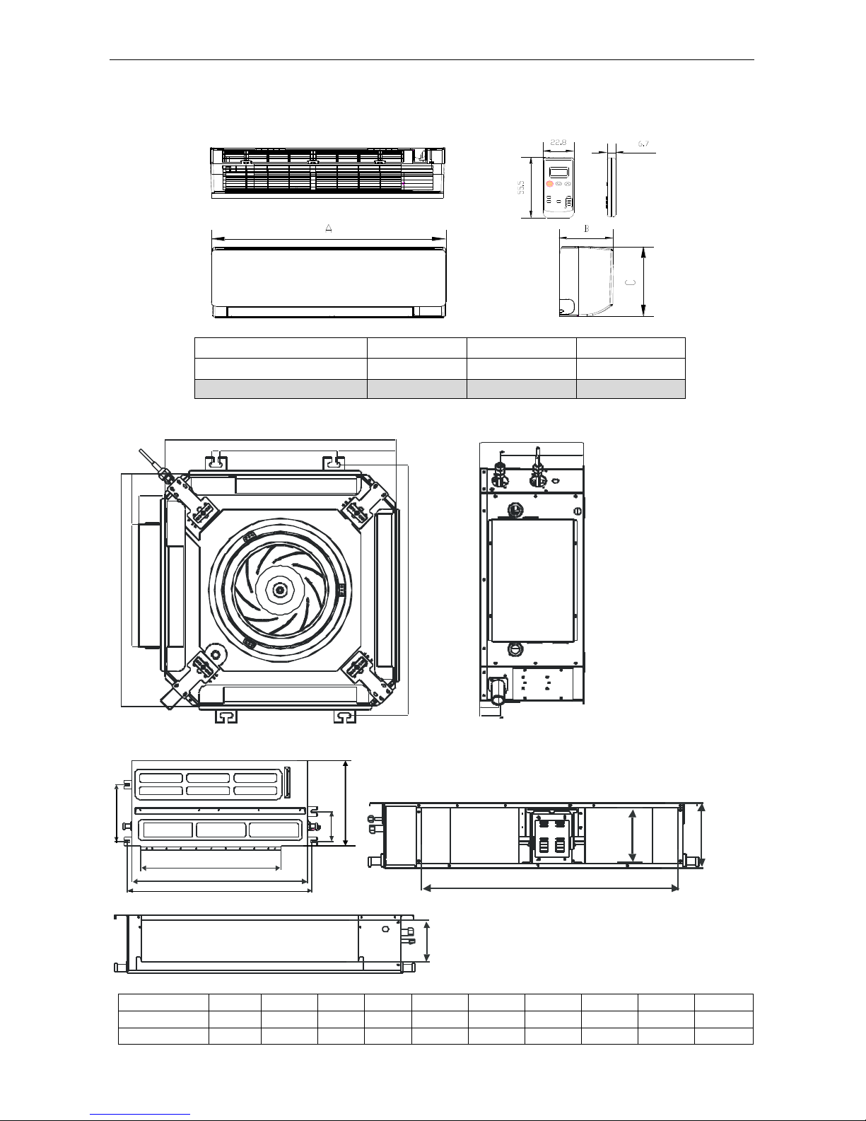
3. Product Dimensions
Indoor Unit:
Wall split type
Model
A B C
9K
810
292
198
12K
810
292
198
Cassette type
574
19
620
304
574
124
64
144
293
50
113
95
255
45
Duct type
Model
A B
C D E F G H I J 7/9/12K
700 450
200
570
172
510
140
738
298
158
18K
925 450
200
790
172
730
140
958
298
158
A H F
I
J B E C G
D
Page 4
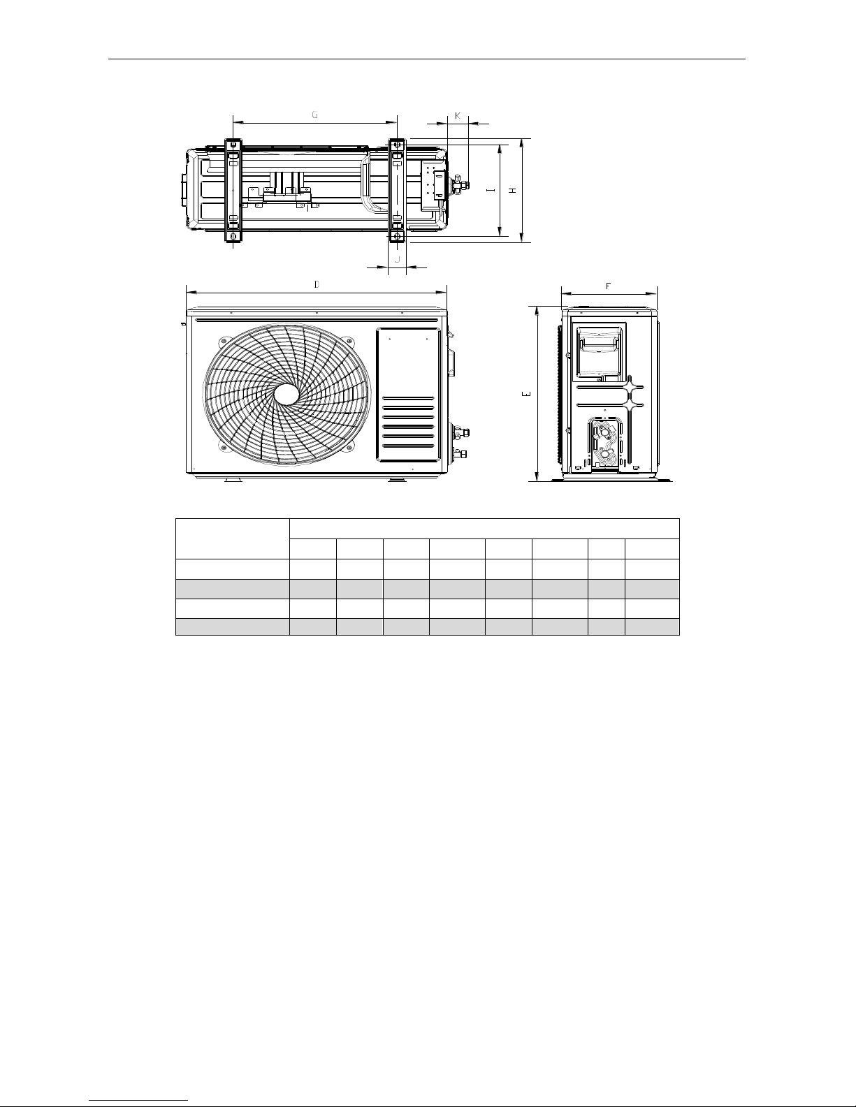
Air Conditioner Service Manual
3
Outdoor Unit:
Model
Outdoor unit
D E F G H I J
K
14000BTU
780
605
290
521
360
327.5
55
56
18000BTU
780
605
290
521
360
327.5
55
56
21000BTU
900
660 310
623
374
347
61
56
24000BTU
940
910
340
600
400
375
80
56
Page 5
Air Conditioner Service Manual
4
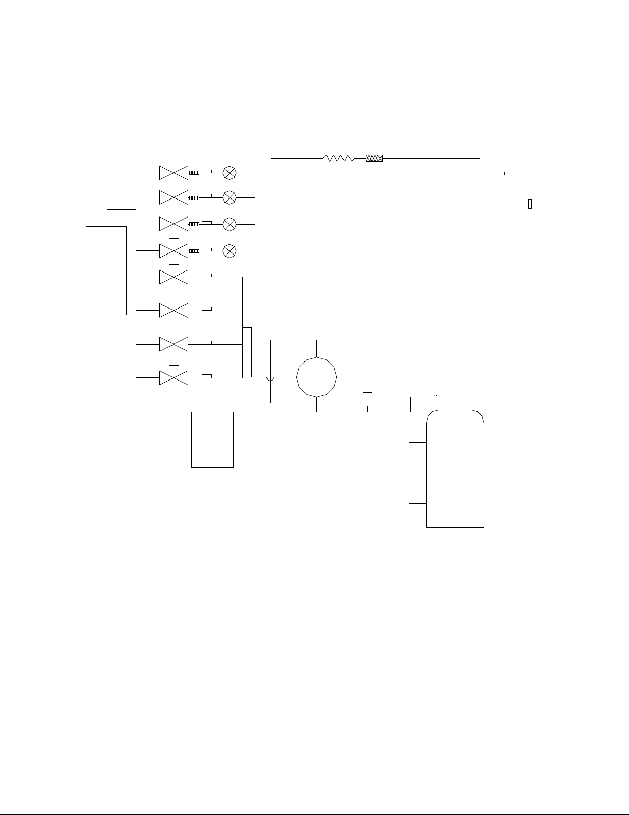
4. Refrigeration cycle diagram
TIN1
PMV1
TIN2
TIN3
PMV2
PMV3
PMV4
TIN4
T2B1
T2B2
T2B3
T2B4
ST
CONDENSER
liquid
storage
pot
T3
T4
TP
HP
COMPRESSOR
Optional
Evaporator
Page 6
Air Conditioner Service Manual
5
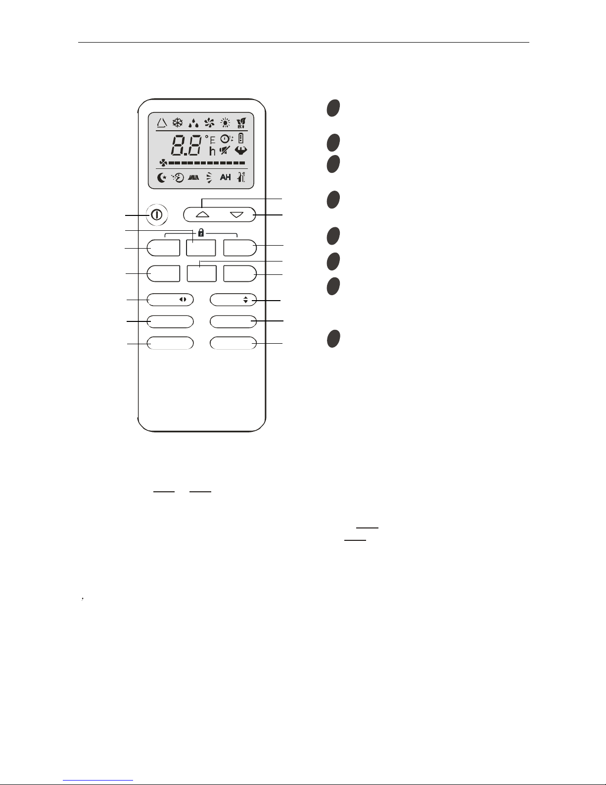
5. Operation details
Remote controller
Note: Each mode and relevant function will be further specified in following pages.
Remote controller:
The remote controller is not preset as Cooling Only Air Conditioner or Heat Pump by manufacturer.
Each time after the remote controller replace batteries or is energized, the arrowhead will flashes
on the front of Heat or Cool on LCD of the remote controller.
User can preset the remote controller depending on the air conditioner type you have purchased as
follows:
Press any button when the arrow head flashes on the front of Cool, Cooling Only is set.
Press any button when the arrow head flashes on the front of Heat, Heat Pump is set.
If you don’ t press any button within 10 seconds, the remote controller is preset as Heat Pump
automatically.
Note:
If the air conditioner you purchased is a Cooling Only one, but you preset the remote controller as
Heat Pump, it doesn’t bring any matter. But if the air conditioner you purchased is a Heat Pump one,
and you preset the remote controller as Cooling Only, then you CAN NOT preset the Heating
operation with the remote controller.
1
ON/OFF button
2
Swing control button
3
FAN SPEED control button
Used to select the indoor fan motor
speed: AUTO, High, Mid and Low
Used to star and stop operation
when pressed.
Used to adjust airflow direction
Used to decrease the set room
temperature and time.
5
SLEEP button
Used to set or cancel sleep mode operation.
6
TIMER button
Used to set select TIMER operation.
7
MODE button
Used to select the type of operation mode:
Feel, Cooling, Dry, Fan and Heating (Only for
Heat Pump).
8
DOWN button
4
UP button
Used to decrease the set room temperature
and time.
MODE
FAN SLEEP
ECO TIM ER
SWING
TURBOMUTE
DISPLAY
SWING
HE ALTHI FE EL
1
2
3
4
5
6 7 8 9 10
11
12
13
14
15
Page 7

Air Conditioner Service Manual
6
Electronic Controller
1. Safety Protection
(1) Time Delay for Safety protection
3 minutes delay for compressor ---The compressor is ceased for 3minutes before restarting
to balance the pressure in the refrigeration cycle in order to protect the compressor.
150 seconds delay for 4-way valve---The 4-way valve will be ceased for 150 seconds
late after compressor to prevent the refrigerant-gas abnormal noise when the HEATING
operation is OFF or switch to the other operation mode.
(2) Discharge temperature protection
There is a temperature sensor on discharge pipe, when temperature on discharge pipe
exceeded the limit 115℃, system control will shut down the compressor and the display board
will show the error code.
(3) Lower voltage protection
When AC voltage <160V, DC voltage<170V, unit will be shut down for protection and recover while
the AC voltage ˃170 V, DC voltage ˃190V.
(4) Over voltage protection
When AC voltage ˃ 275V, DC voltage ˃400V unit will be shut down and recover while AC
voltage<255V, DC voltage<390 V.
(5) Over current protection
When the current of outdoor unit is overload, controller will drop the operation frequency or shut
down the unit immediately and show error code.
(6) Condenser temperature protection
When condenser temperature≥ 65℃ and keep 10s, the air conditioner will shut down, and
show error code, and recover while condenser temperature<52℃ and the compressor stop for
3minutes.
(7) IPM module protection
IPM module has high temperature & over current protection itself, if there is signal feedback to
IPM, the outdoor unit will shut down, LED on outdoor PCB will show the error code.
(8) Evaporator freeze protection.
When evaporator temperature<2℃, the controller will drop compressor operate frequency.
When evaporator temperature<0℃ and keep 1 minute, the expand valve of the unit will stop.
When all of the operating unit enter freeze protect, the compressor will stop and recover while
evaporator temperature and stop for 3 minutes.
2. “Feel” Mode Operation
(1) When the “Feel” mode is selected, the operation mode and initial temperature set are
determined by the initial room temperature at start-up of the operation except to turn off the air
conditioner and operates it again.
(2) If the unit have activate the AUTO restart, when the power off and supply again, the unit will
judge the condition again and enter the “Feel” mode.
(3) If the mode is change to “Feel” from other mode, the “Feel” mode doesn’t operate until
compressor stop for more than 3 minutes.
Mode
Initial Room Temperature
Initial Set Temperature
COOLING
RT=26℃
23℃
DRY
26℃>RT≥20℃
RT-2℃
HEATING
RT<20℃
23℃
Fan
RT<20℃
RT
Page 8
Air Conditioner Service Manual
7
In the “Feel” mode, when the controller receives the up or down signal of temperature,
the set
temperature can adjust by 1℃ upper or lower. The biggest you can adjust by 2℃ upper or lower.
3. “COOLING” Mode Operation
(1) Compressor frequency control
According to difference room temperature and set temperature (δt = RT-ST), running frequency
of compressor is controlled by electronic controller. When room temperature is much higher than
set temperature, the compressor will start at a high frequency, and as room temperature goes
down, the compressor running frequency will go down. When room temperature is lower than set
temperature, the compressor will run at very low frequency. In general, unit will change its running
frequency according to δt to make room temperature closing to set temperature.
(2) Outdoor temperature affects running frequency of the compressor
Outdoor temperature affect compressor’s running frequency. Difference inlet temperature of
outdoor unit is adapted by difference compressor running frequency. While outdoor temperature is
about 30℃, the compressor will run in high frequency.
If unit run in “cooling” mode and outdoor temperature is less than -2℃,the controller will shut
down compressor and show error code, while the ambient temperature is over 1℃, the compressor
will run automatically.
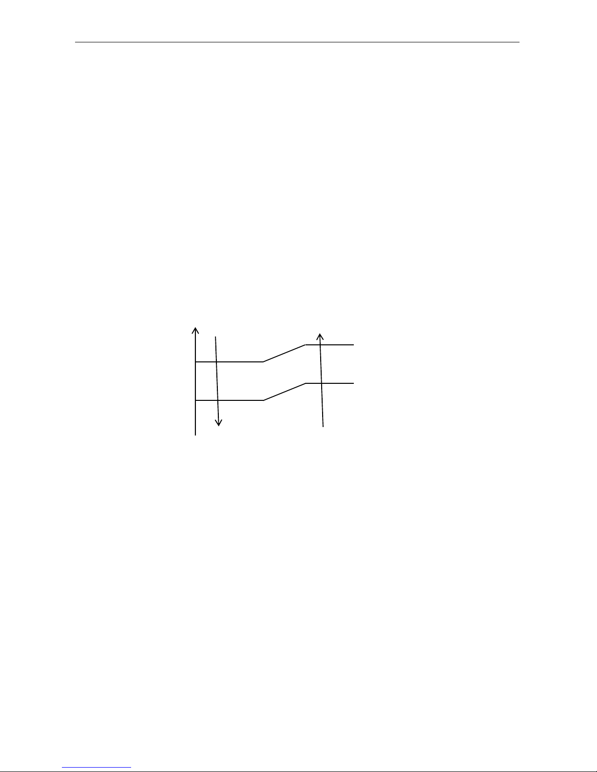
(3) Auto fan control in cooling mode
In cooling mode (include cooling in “Feel” mode), fan speed is determined by δt, as the
following diagram:
4.“DRY” Mode Operation
(1) The system for DRY operation used the same refrigerant circle as the cooling one.
(2) When the system operates in DRY mode, at first it operates in cooling mode, the set
temperature (ST) is “RT-2℃”. After that, the system will operate in cooling mode with
lowest fan speed. During the course of this operation, you can’t use remote controller to adjust
the fan speed but you can control the vane direction.
(3) In the dry mode, when RT≤12℃, the compressor will stop and operates again at RT≥14℃.
5. “HEATING” Mode Operation (available for Heat Pump only)
(1) Frequency control
Same as the frequency control in cooing mode, the running frequency of compressor is
controlled by controller. Unit change its running frequency according to δt to make the room
temperature closing to the set temperature.
(2) Indoor fan motor control
1) Cold Air Prevention Control
The function is intended to prevent cold air from being discharged when heating mode
selected or while in defrosting.
The indoor fan speed will be controlled as following.
RT-ST
℃
4.0
3.0
1.5
1.0
δt come down
δt come up
High fan
Min fan
Low fan
Page 9

Air Conditioner Service Manual
8
In heating operation, if air conditioner turn off, the indoor fan motor will run most for 30
seconds since the stop of compressor.
2) Auto fan control (heating)
In heating mode (include in “feel” mode) , fan speed is determined by δt as the following:
(3) 4-way valve control
In heating mode, 4-way valve will power on ahead of compressor for 8 seconds, and cut off
for 2 minutes later than compressor. 4-way valve will not power off unless the machine to be
switched off, mode changed or on the process of defrosting.
(4) Outdoor fan motor control
In heating mode, the outdoor fan motor will power on ahead of compressor 5 seconds, and
cut off for 30seconds later than compressor.
(5) Defrosting
Defrosting is controlled by the microprocessor.
When the unit operate 30 minutes accumulated and the compressor operation more than 3
minutes continuously, one of the following conditions is satisfied, unit comes into defrosting:
a.
When FrostDeg ≥ -5℃, and OPT ≤ -5℃, the .2 times defrosting interval time is 45 minutes.
b.
When -10℃≤ FrostDeg < -5℃, and OPT < FrostDeg , the .2 times defrosting interval time is
45 minutes.
c.
When -13℃≤ FrostDeg < -10℃, and OPT < FrostDeg , the .2 times defrosting interval time is
RT-ST
δt come down
δt come up
℃
Breeze
Temperature up
Temperature down
Setting
Low fan
Stop
37℃
33℃
25℃
33℃
25℃
20℃
4.0
3.0
1.5
1.0
High fan
Min fan
Low fan
Indoor pipe Temperature
3S
5S
30S
120S
ON
OFF
ON
ON
OFF
OFF
4-WAY valve
Outdoor fan motor
Compressor
5S
30S
ON
ON
OFF
OFF
Outdoor fan motor
Compressor
Page 10

Air Conditioner Service Manual
9
45 minutes.
d.
When -15℃≤ FrostDeg < -13℃, and OPT < FrostDeg , the .2 times defrosting interval time is
65 minutes.
e.
When -15℃≤ FrostDeg < -10℃, and OPT < FrostDeg , the .2 times defrosting interval time is
75 minutes.
f.
When FrostDeg < -15℃, and OPT < -15℃, the .2 times defrosting interval time is 75 minutes.
FrostDeg = C*OAT-α
OAT: Outdoor environment temperature.
When OAT< 0℃, C=0.8, when OAT≥ 0℃, C=0.6
α=8
Before the air con comes into defrosting, compressor running frequency drop down to a
lower frequency firstly, then the compressor shuts down.
In defrosting, all protection function are available.
T1 T2 T3 T4 T5 T7 T8 T9 T10T6
Compressor Frequency
Outdoor Fan Motror
4-way Valve
ON
OFF
ON
OFF
ON
OFF
Defrost Hightest Frequency
T
T1
T2
T3
T4
T5
T6
T7
T8
T9
T10
Times
Drop frequency
or stop
50s
5s
5s
Rise
frequency
2-11Min
Stop
Defrost
50s
10s
Rise frequency
In defrosting, LED showing by winking.
No matter what AC come into or out of defrosting, indoor fan motor speed is the same as
Cold Air Prevention Control.
While one of the following conditions is satisfied, unit comes out of defrosting and shifts to
heating mode:
a.
Outdoor coil Temperature (OPT) >5℃ and keeps 30 seconds.
b.
Outdoor coil Temperature (OPT) >10℃ and keeps 2 seconds.
c.
Continue 11minutes defrost Operation.
(5) Indoor exchanger overheat protection
When Indoor exchanger Temperature (IPT) is higher than 54℃ , unit comes into indoor exchanger
overheat protection. The compressor drops its frequency.
If IPT≥65℃ and keep for 30 seconds, control system shut down compressor, and recover while IPT
drop less than 52℃.
6. “SLEEP” mode
When the SLEEP button is pressed, the AC operates as following:
The indoor fan speed is set at low speed, the power lamp and the sleep lamp is on,
the display of temperature will close after 30 seconds.
When selecting COOLING/DRY operation with SLEEP mode, the set temperature will be
raised by 1℃ 1 hour later and by 2℃ 2 hour later, after 3 hours, the set temperature will be
raise by 3℃ and keeps 2hours. And then the temperature is Set+2℃, after 1 hour, the
temperature is set temperature and keep.
Page 11

Air Conditioner Service Manual
10
When selecting HEATING operation with SLEEP mode, the set temperature will be dropped
by 1℃1 hour later and 2℃ 2 hours later, after 3 hours, the set temperature will be dropped by
3℃ and keep 2 hours. And then the temperature is Set-2℃, after 1 hour, the temperature is
set temperature and keep.
7. EMERGENCY Operation
When the EMERGENCY Operation switch is pressed, “Beep” a short sound, COOLING mode
is selected, two short sound the HEATING mode selected, and a long sound the unit off of 3s.
During the unit operation in emergency operation, when the unit receive the signal of remote
controller, the unit will operates by remote.
When the remote controller missing, failed or the batteries run down, press the EMERGENCY
Operation switch on front of the indoor unit for function test.
NOTE: Do not press the EMERGEMCY Operation switch during normal operation.
8. AUTO-RESTART Function (Option)
While air conditioner is operating in one mode, all of its operation data, such as working
mode, preset temperature etc. would be memorized into IC by main PCB. If power supply cut off
due to reasons and recover again, the AUTO-RESTART function will set synchronously and
the air conditioner would work at the same mode as before.
Auto-restart Pre-setting (optional):
If Auto-restart function is needed, follow the steps below to activate this function:
1) Pulling the air-con's plug out of socket.
2) Pressing and holding the Emergency button (ON/OFF) on the indoor, then insert the plug
into the socket again.
3) Keep pressing the Emergency button for more than 10 seconds until three short beeps
heard, the Auto-restart function been activated.
4) When the unit in operation, press the timer button 10 times in 8s, the Auto-restart
function will be active,if the Auto-restart is active, the Auto-restart off.
9. Water pump control(cassette and duct type)
When the unit operates in cool or dry mode, the water pump operates, once the compressor
off or change to other mode, the water pump stop after 10 minutes.
Anytime, when the unit check the water full, the water pump operates, the unit stop and
display the water full code. When the water full eliminate, the water pump will stop after 10
minutes.
When check the water pump switch open for 8 seconds continuous, enter water full
protection, and check the water pump switch on for 180 seconds continuous, the water full
protection exit.
10. Protection and Failure Display
When protection display is available, controller will show error code, digital LED shows
error code and setting temperature by turns.
If there is more than one failure, it will show error codes according to the error list sequence.
To insure the signal communication of indoor and outdoor unit, any failure code relates to
outdoor unit will remain display for 2 minutes maximum after it’s recovered.
Among all the failure codes, sensor failure can be recovery automatically once it comes normal.
Page 12
Air Conditioner Service Manual
11
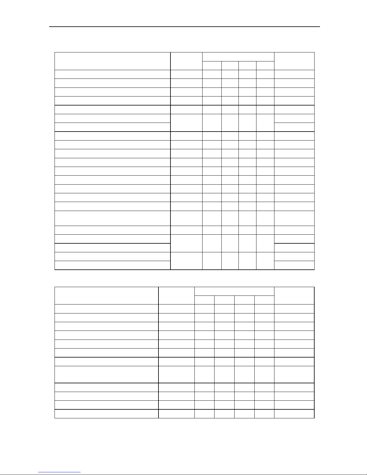
Error list
Failure Type
Indoor LED
Code
CASSETTE
Outdoor light
blink time (n)
LED1
LED2
LED3
LED4
Indoor and outdoor communication failure
E0
● ● ●
7
Outdoor communication failure
EC
●
●
15
Indoor room temperature sensor (IRT)
E1
● ● ●
25
Indoor coil temperature sensor (IPT)
E2
●
●
26
Outdoor coil temperature sensor (OPT)
E3
● ● ●
10
IPM over current protect
E4
● ◎ ●
◎
40
Compressor phase-deficient operation
34
Model configuration wrong
E5
●
●
29
Indoor fan motor fault
E6 ● 21
Outdoor temperature sensor
E7
● ● ●
9
Exhaust temp. sensor
E8
●
●
11
IPM drive and module fault
E9 ● 30
Outdoor fan motor fault (DC motor)
EF
16
Current sensor fault
EA ● 13
Indoor EEPROM fault
EE ● 27
Outdoor EEPROM fault
EE ● 19
Temp. switch fault ( on top of the
compressor)
EP
- - -
-
8
Voltage sensor fault
EU
○ ● ●
12
Outlet temperature sensor A fault
Ey
○
● ◎ ●
47
Outlet temperature sensor B fault
48
Inlet temperature sensor A fault
En
○
● ◎ ◎
51
Inlet temperature sensor B fault
52
Protection display code list:
○--light ●--off ◎—flash
Outdoor failure display
Protection Type
Indoor LED
Code
CASSETTE
Outdoor light
blink time (n)
LED1
LED2
LED3
LED4
Overvoltage /lower voltage protection
P1
○
●
●
○
2
Overcurrent protection
P2
○ ● ○
●
3
Overvoltage protection
P3
○ ● ○
○
24
Discharge over temperature
P4
○ ○ ●
●
4
Too cool protection in cooling mode
P5
- - -
-
32
Overheat protection in cooling mode
P6
○ ○ ○
●
5
Overheat protection in heating mode
P7
○ ○ ○
○
33
Outdoor over temperature
/ lower temperature protection
P8
- - -
-
31
Drive protection (software control )
P9
- - -
-
6
Module protection (hardware control)
P0
- - -
-
1
Model different
PA
● ● ○
○
-
Water full protect
D3
● ○ ○
-
Page 13
Air Conditioner Service Manual
12
There is a LED on outdoor power board, it blinks 1s ON and 1s OFF while compressor standby and
it always light (ON) while compressor running; If there is failure happened on ODU, The indicator (LED)
alerts the fault in a cycle as such that it is bright for 0.5 seconds, dark for 0.5 seconds, blinks “n” times
and then dark for 3 seconds. For details as table below.
Display on outdoor power source board:
blink time (n)
Failure
1
IPM protection
2
Over voltage /lower voltage
3
Overcurrent
4
Exhaust over temperature protection
5
Outdoor coil over temperature protection
6
Drive fault and protection (V1,VP1)
7
Communication fault with indoor unit
8
Compressor overheat fault (compressor top switch)
9
Short-circuit / open-circuit fault of outdoor temperature sensor
10
Short circuit / open-circuit fault of outdoor heat exchanger temperature
11
Short-circuit / open-circuit fault of exhaust temperature sensor
12
Voltage sensor fault
13
Current sensor fault
14
IPM fault
15
Communication fault between power source board and IPM
16
No feedback from DC fan motor(outdoor unit)
17
Defrost state
Page 14
Air Conditioner Service Manual
13
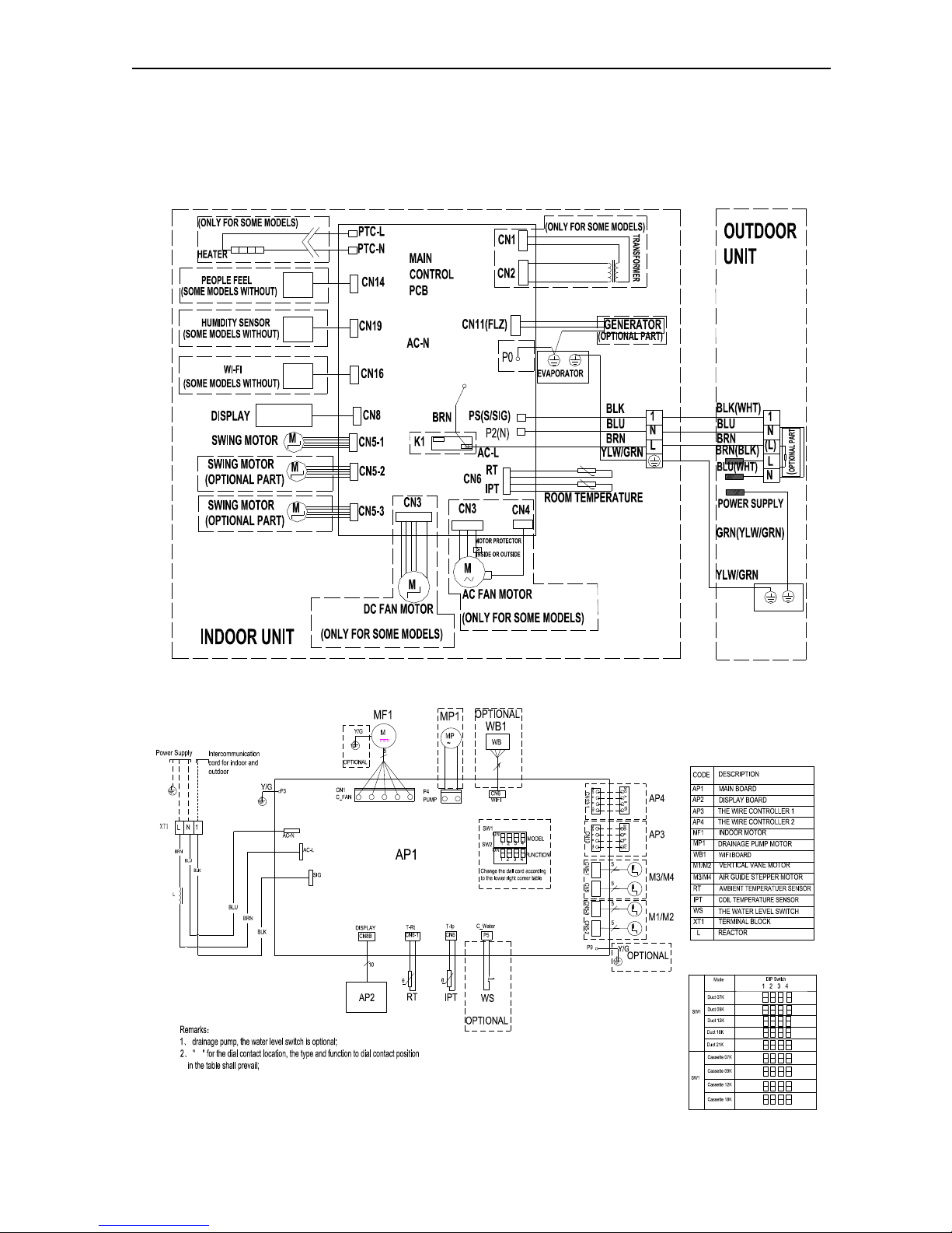
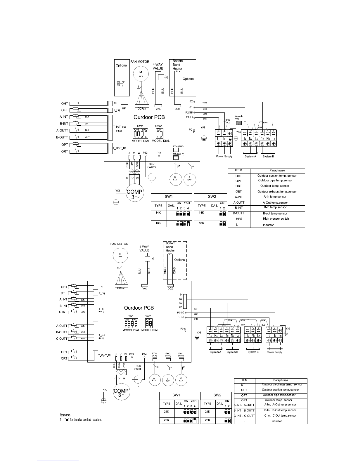
6. Wiring diagram
INDOOR UNIT:
Wall split type:
Cassette, Duct type:
Page 15
Air Conditioner Service Manual
14
OUTDOOR UNIT
ONE TO 2 TYPE:
ONE TO 3TYPE:
Page 16
Air Conditioner Service Manual
15
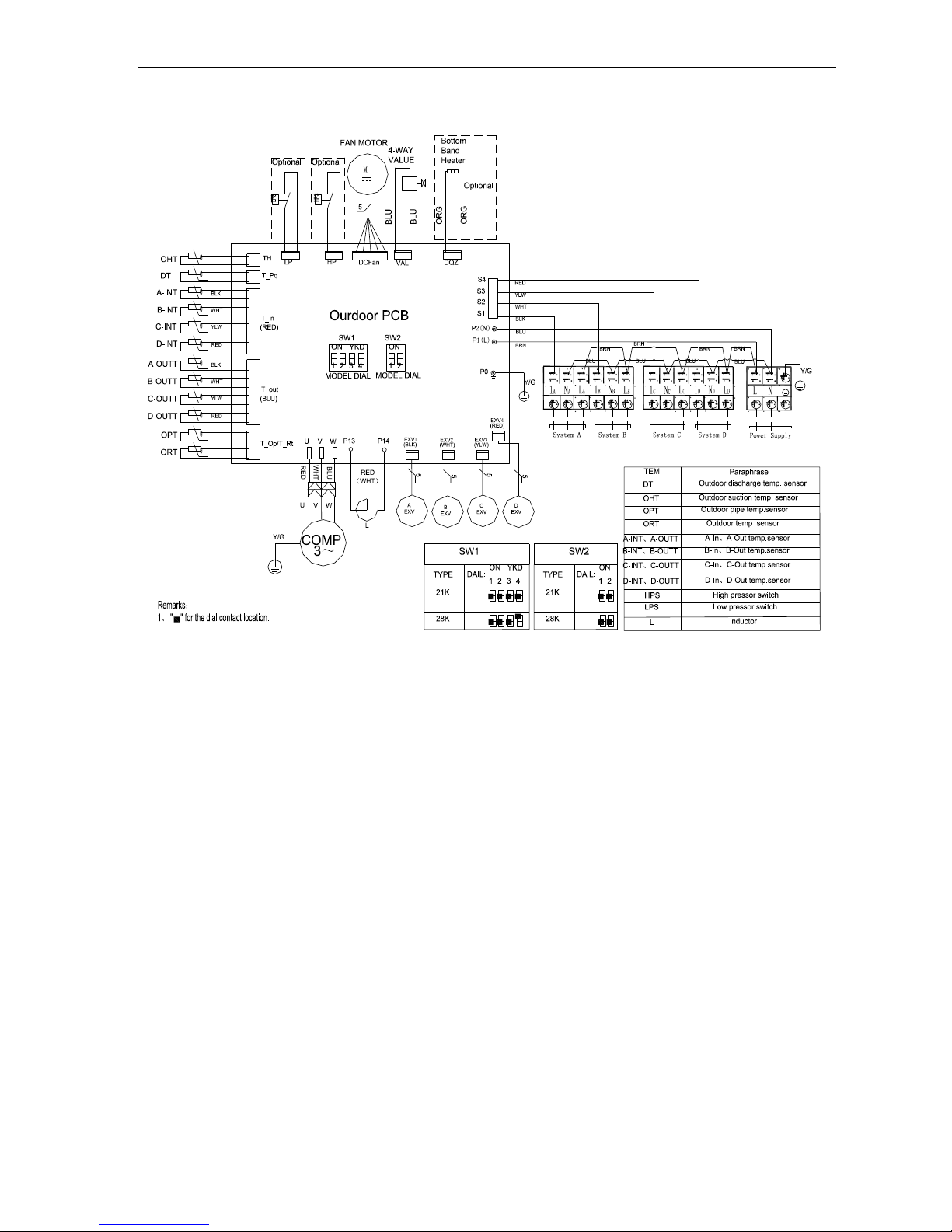
ONE TO 4 TYPE
Page 17
Air Conditioner Service Manual
16
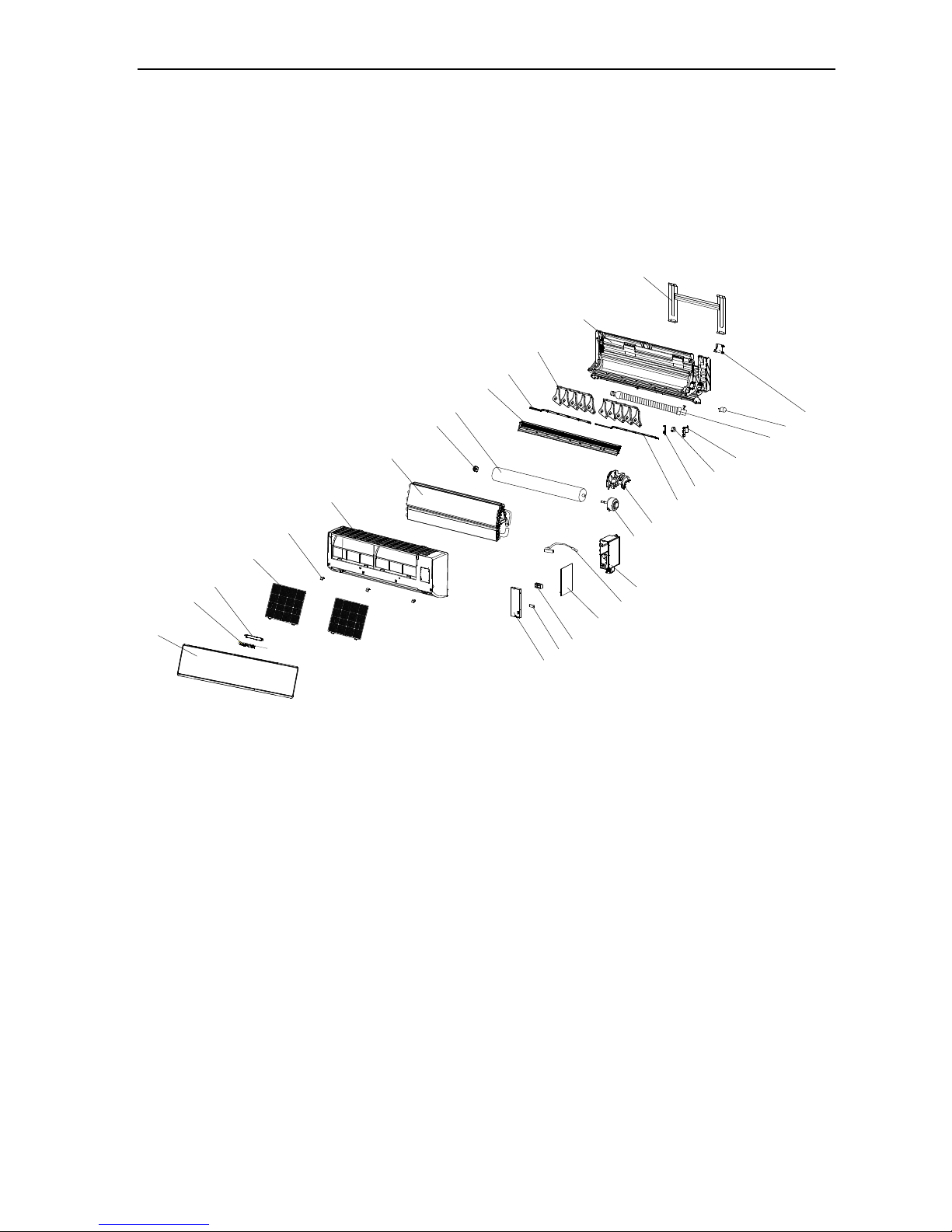
7. Explosion view and parts
WALL SPLIT TYPE: TACM-09HRIA/EW, TACM-12HRIA/EW
INDOOR UNIT:
14
13
12
11
10
9
8
7
6
5
4
3
2
1
15
16
17
20
19
18
21
22
23
24
25
26
27
28
29
Page 18
Air Conditioner Service Manual
17
Parts List
Wall split type- TACM-09HRIA/EW
No.
Part No.
Part Name
Q’ty
Remark
1
1080030021
Installation Plate
1
2
210737661G
Base
1
3
210701883
Vertical Vane Assembly
2
4
210738167
Left Vertical Vane Connector
1
5
210737671
Vane
1
6
210737666
Cross Fan
1
7
1070100010
Bearing Mount
1
8
211236178G
Evaporator
1
9
210737669
Face Frame
1
10
210701846
Screw Cover
1
11
210703004
Air Filter
2
12
1070250120
Display PCB Box
1
13
1090250119AQ
Display PCB
1
14
210738178C
Front Panel
1
15
210737654
Electrical Box Cover
1
16
210736912
Cable Clamp
1 17
210900478A
Terminal
1
18
210900333
Indoor Sensor Assembly
1
19
210901628
Main PCB
1
20
210736831
Electrical Box
1
21
1170030067G
Indoor Motor
1
22
210737665
Indoor Motor Cover
1
23
210738168
Right Vertical Vane connector
1
24
210737668
Step Motor connector
1
25
210900129
Step Motor
1
26
210738225
Step Motor Supporter
1
27
210737091
Drainage Hose
1
28
1170020011
Vane Motor
1
29
210736813
In And Out Pipe Fixer
1
30
210901521B
Remote Controller
1
Not shown in Explosion view
31
1190540002ACW
Indoor Carton
1
32
211363352
Left Foaming
1
33
211363353
Right Foaming
1
Page 19

Air Conditioner Service Manual
18
Wall split type- TACM-12HRIA/EW
No.
Part No.
Part Name
Q’ty
Remark
1
1080030021
Installation Plate
1
2
210737661G
Base
1
3
210701883
Vertical Vane Assembly
2
4
210738167
Left Vertical Vane Connector
1
5
210737671
Vane
1
6
210737666
Cross Fan
1
7
1070100010
Bearing Mount
1
8
211236178G
Evaporator
1
9
210737669
Face Frame
1
10
210701846
Screw Cover
1
11
210703004
Air Filter
2
12
1070250120
Display PCB Box
1
13
1090250119AQ
Display PCB
1
14
210738178C
Front Panel
1
15
210737654
Electrical Box Cover
1
16
210900478A
Terminal
1
17
210736912
Cable Clamp
1
18
210900333
Indoor Sensor Assembly
1
19
210901628A
Main PCB
1
20
210736831
Electrical Box
1
21
1170030067G
Indoor Motor
1
22
210737665
Indoor Motor Cover
1
23
210738168
Right Vertical Vane connector
1
24
210737668
Step Motor connector
1
25
210900129
Step Motor
1
26
210738225
Step Motor Supporter
1
27
210737091
Drainage Hose
1
28
210736813
In And Out Pipe Fixer
1
29
1170020011
Vane Motor
1
30
210901521B
Remote Controller
1
Not shown in Explosion view
31
1190540002ACX
Indoor Carton
1
32
211363352
Left Foaming
1
33
211363353
Right Foaming
1
Page 20

Air Conditioner Service Manual
19
WALL SPLIT TYPE: TACM-09HRIA/E1, TACM-12HRIA/E1
INDOOR UNIT:
24
20
22
18
17
16
15
14
13
12
11
10
9
8
7
6
5
4
3
2
1
21
19
23
Page 21

Air Conditioner Service Manual
20
Wall split type- TACM-09HRIA/E1
No.
Part No.
Part Name
Q’ty
Remark
1
1080030021
Installation Plate
1
2
210737661D
Base
1
3
210701880C
Vertical Vane Assembly
2
4
210737666
Cross Fan
1
5
1070100010
Bearing Mount
1
6
211236178G
Evaporator
1
7
210737669
Face Frame
1
8
210701846
Screw Cover
2
9
210737672
Vane
1
10
210703004
Air Filter
2
11
210705767
Display PCB Box
1
12
210901127S
Display PCB
1
13
210754504
Front Panel
1
14
210737654
Electrical Box Cover
1
15
210736912
Cable Clamp
1
16
210900478A
Terminal
1
17
210901628
Main PCB
1
18
210900333
Indoor Sensor Assembly
1
19
210736831
Electrical Box
1
20
1170030067G
Indoor Motor
1
21
210737665
Indoor Motor Cover
1
22
210701101AA
Drainage Hose
1
23
1170020011
Vane Motor
1
24
210736813
In And Out Pipe Fixer
1
25
210901521B
Remote Controller
1
Not shown in Explosion view
26
1190540002ACY
Indoor Carton
1
27
211370970
Left Foaming
1
28
211370971
Right Foaming
1
Page 22

Air Conditioner Service Manual
21
Wall split type- TACM-12HRIA/E1
No.
Part No.
Part Name
Q’ty
Remark
1
1080030021
Installation Plate
1
2
210737661D
Base
1
3
210701880C
Vertical Vane Assembly
2
4
210737666
Cross Fan
1
5
1070100010
Bearing Mount
1
6
211236178G
Evaporator
1
7
210737669
Face Frame
1
8
210701846
Screw Cover
2
9
210737672
Vane
1
10
210703004
Air Filter
2
11
210705767
Display PCB Box
1
12
210901127S
Display PCB
1
13
210754504
Front Panel
1
14
210737654
Electrical Box Cover
1
15
210736912
Cable Clamp
1
16
210900478A
Terminal
1
17
210901628A
Main PCB
1
18
210900333
Indoor Sensor Assembly
1
19
210736831
Electrical Box
1
20
1170030067G
Indoor Motor
1
21
210737665
Indoor Motor Cover
1
22
210701101AA
Drainage Hose
1
23
1170020011
Vane Motor
1
24
210736813
In And Out Pipe Fixer
1
25
210901521B
Remote Controller
1
Not shown in Explosion view
26
1190540002ACY
Indoor Carton
1
27
211370970
Left Foaming
1
28
211370971
Right Foaming
1
Page 23

Air Conditioner Service Manual
22
CASSETTE TYPE:
INDOOR UNIT:
Page 24

Air Conditioner Service Manual
23
Cassette type- TQCM-12HRIA,TQCM-12HRIA
NO.
Part NO.
Part Name
Qty
Remark
1
/
Indoor chassis
1
2
230900366
Indoor motor
1
3
230701325
Indoor fan
1
4
/
Base of evaporator
1
5
/
Evaporator
1
6
/
Capacitor of indoor motor
1
7
1170200061
Terminal
1
8
/
Drain pan
1
9
230701669
Panel
1
10
/
Vane
1
11
230904459
Display PCB
1
12
230904486
Swing motor
4
13
230901784A
Inductor
1
14
230901484A
Indoor main PCB
1
15
230901539
Pump
1
16
230901538
Water level switch
1
17
210900414A
Remote controller
1
Not shown in explosion view
18
3160130006
Indoor pipe sensor
1
19
3160130011
Indoor room sensor
1
Page 25
Air Conditioner Service Manual
24
Cassette type- TQCM-18HRIA
NO.
Part NO.
Part Name
Qty
Remark
1
/
Indoor chassis
1
2
230900366
Indoor motor
1
3
230701325
Indoor fan
1
4
/
Base of evaporator
1
5
/
Evaporator
1
6
/
Capacitor of indoor motor
1
7
1170200061
Terminal
1
8
/
Drain pan
1
9
230701669 Panel
1
10
/
Vane
1
11
230904459
Display PCB
1
12
230904486
Swing motor
4
13
230901784A
Inductor
1
14
230901484A
Indoor main PCB
1
15
230901539
Pump
1
16
230901538
Water level switch
1
17
210900414A
Remote controller
1
Not shown in explosion view
18
3160130006
Indoor pipe sensor
1
19
3160130011
Indoor room sensor
1
Page 26

Air Conditioner Service Manual
25
DUCT TYPE:
INDOOR UNIT:
1
2
3
4
6
5
7
8
9
10
11
12
13
14 15
16
17
18
24
7
23
22
19
20
21
Page 27

Air Conditioner Service Manual
26
DUCT TYPE- :TDCM-07HRIA, TDCM-09HRIA
NO.
Part NO.
Part Name
Pty
Remark
1
230801045
Front plate
1
2
230801031
Indoor chassis
1
3
230700620
Drain pan
1
4
230801046
Inlet plate
1
5
231202769A
Evaporator
1
6
230801080
Left plate
1
7
230800420
Installation holder
4
8
230801118
Space plate
1
9
230801442
Motor supporter
1
10
230700626
Down Vortex
2
11
230801048
Indoor fan
2
12
230700628
Up Vortex
2
13
230801117
Top plate
1
14
230800425A
Left motor holder
1
15
230901635
Indoor motor
1
16
230800426A
Right motor holder
1
17
230801115
Electrical box installation plate
1
18
230801038
Electrical box
1
19
230901484A
Main PCB
1
20
230901784A Inductor
1
21
230900237
Display PCB
1
22
230801039
Electrical box cover
1
23
230801090
Pipe cover plate
1
24
230801081
Right plate
1
25
210900414A
Remote controller
1
Not shown in explosion view
26
230901285
Indoor pipe sensor
1
27
3160130011
Indoor room sensor
1
Page 28
Air Conditioner Service Manual
27
DUCT TYPE- :TDCM-12HRIA
NO.
Part NO.
Part Name
Pty
Remark
1
230801045
Front plate
1
2
230801031
Indoor chassis
1
3
230700620
Drain pan
1
4
230801046
Inlet plate
1
5
231202769A
Evaporator
1
6
230801080
Left plate
1
7
230800420
Installation holder
4
8
230801118
Space plate
1
9
230801442
Motor supporter
1
10
230700626
Down Vortex
2
11
230801048
Indoor fan
2
12
230700628
Up Vortex
2
13
230801117
Top plate
1
14
230800425A
Left motor holder
1
15
230901635
Indoor motor
1
16
230800426A
Right motor holder
1
17
230801115
Electrical box installation plate
1
18
230801038
Electrical box
1
19
230901484A
Main PCB
1
20
230901784A
Inductor
1
21
230900237
Display PCB
1
22
230801039
Electrical box cover
1
23
230801090
Pipe cover plate
1
24
230801081
Right plate
1
25
210900414A Remote controller
1
Not shown in explosion view
26
230901285
Indoor pipe sensor
1
27
3160130011
Indoor room sensor
1
Page 29

Air Conditioner Service Manual
28
DUCT TYPE- :TDCM-18HRIA
NO.
Part NO.
Part Name
Pty
Remark
1
230801044
Front plate
1
2
230801032
Indoor chassis
1
3
230700621
Drain pan
1
4
230801052
Inlet plate
1
5
231202183A
Evaporator
1
6
230801080
Left plate
1
7
230800420
Installation holder
4
8
230801116
Space plate
1
9
230801443
Motor supporter
1
10
3070060021
Down Vortex
2
11
3070020001A
Indoor fan
2
12
3070060020
Up Vortex
2
13
230801079
Top plate
1
14
230800425A
Left motor holder
1
15
230901635
Indoor motor
1
16
230800426A
Right motor holder
1
17
230801115
Electrical box installation plate
1
18
230801038
Electrical box
1
19
230901484A
Main PCB
1
20
230901784A
Inductor
1
21
230900237
Display PCB
1
22
230801039
Electrical box cover
1
23
230801090
Pipe cover plate
1
24
230801081
Right plate
1
25
210900414A
Remote controller
1
Not shown in explosion view
26
3160130004
Indoor pipe sensor
1
27
3160130011
Indoor room sensor
1
Page 30

Air Conditioner Service Manual
29
OUTDOOR UNIT:
10
11
12
8
9
7
6
5
17
13
14
16
15
19
18
20
21
23
4
3
2
1
22
24
Page 31
Air Conditioner Service Manual
30
OUTDOOR UNIT- TACM2O-14HIA
No.
Part No.
Part Name
Q’ty
Remark
1
210701820
Grille
1
2
210800251
Top cover 1
3
231235682
Condenser 1
4
1080050130
Outdoor motor supporter
1
5
210900219
Outdoor motor 1
6
1070030054AA
Propeller fan 1
7
1081990053
Left grille supporter
1
8
210800250
Front plate 1
9
210701513
Fan guard 1
10
211203447
Compressor and accessories
1
11
1120110016A
4-way valve 1
12
231235633
4-way valve assembly
1
13
210800281
Base
1
14
210800252C
Right plate 1
15
231202639
Two-way valve 2
16
230802035
Valve supporter 1
17
3120120048
Three-way valve 2
18
1070350971
Electrical box cover
1
19
230701494
Cable clamp
1
20
230901989A
Terminal
1
1170200041C
Terminal
1
21
230904192
Outdoor PCB assembly
1
22
1170190004
Inductor
1
23
231235632
Electronic expand valve
1
24
234144007
Partition plate 1
25
1170230027A
Pipe Temp. sensor and
outdoor Temp. sensor
1
Not shown in explosion view
26
1170230006A
Discharge Temp. sensor
1
27
210901787
Expand valve in and out
Temp. sensor
1
28
210901784A
Suction Temp. sensor
1
29
211306934
Base carton
1
30
211306938XR
Cabinet carton
1
31
211306722
Base foaming
1
32
211306721
Cover foaming
1
Page 32

Air Conditioner Service Manual
31
OUTDOOR UNIT- TACM2O-18HIA
No.
Part No.
Part Name
Q’ty
Remark
1
210701820
Grille
1
2
210800251
Top cover 1
3
231235682
Condenser 1
4
1080050130
Outdoor motor supporter
1
5
210900219
Outdoor motor 1
6
1070030054AA
Propeller fan 1
7
1081990053
Left grille supporter
2
8
210800250
Front plate 2
9
210701513
Fan guard 1
10
211232717
Compressor and accessories
1
11
1120110016A
4-way valve 1
12
231235803
4-way valve assembly
1
13
210800281
Base
1
14
210800252C
Right plate 1
15
231202639
Two-way valve 2
16
230802035
Valve supporter 1
17
3120120048
Three-way valve 2
18
1070350971
Electrical box cover
1
19
230701494
Cable clamp
1
20
230901989A
Terminal
1
1170200041C
Terminal
1
21
230904195
Outdoor PCB assembly
1
22
1170190004
Inductor
1
23
231235632
Electronic expand valve
1
24
234144007
Partition plate 1
25
1170230027A
Pipe Temp. sensor and
outdoor Temp. sensor
1
Not shown in explosion view
26
1170230006A
Discharge Temp. sensor
1
27
210901787
Expand valve in and out
Temp. sensor
1
28
210901784A
Suction Temp. sensor
1
29
211306934
Base carton
1
30
211306938XS
Cabinet carton
1
31
211306722
Base foaming
1
32
211306721
Cover foaming
1
Page 33

Air Conditioner Service Manual
32
OUTDOOR UNIT- TACM3O-21HIA
No.
Part No.
Part Name
Q’ty
Remark
1
1071990041
Grille
1
2
1080020023
Top cover 1
3
231235780
Condenser 1
4
1080050112
Outdoor motor supporter
1
5
1170040166D
Outdoor motor 1
6
1070030059
Propeller fan 1
7
1081990040
Left grille supporter
1
8
1080050103
Front plate 1
9
1080050105
Fan guard 1
10
211232717
Compressor and accessories
1
11
1120500226A
4-way valve 1
12
231235750
4-way valve assembly
1
13
210800795
Base
1
14
230803016
Right plate 1
15
231202639
Two-way valve 3
16
3087170101
Valve supporter 1
17
1120130039
Three-way valve 2
3120120048
Three-way valve 1
18
230700661
Electrical box cover
1
19
210735991
Cable clamp
1
230701493
Cable clamp
1
20
230901989A
Terminal
1
1170200041C
Terminal
1
1170200039A
Terminal
1
21
230904196
Outdoor PCB assembly
1
22
230900333
Inductor
1
23
231235767
Electronic expand valve
1
24
230803541
Partition plate 1
25
1170230027A
Pipe Temp. sensor and
outdoor Temp. sensor
1
Not shown in explosion view
26
1170230006A
Discharge Temp. sensor
1
27
210901786
Expand valve in Temp.
sensor
1
28
210901786A
Expand valve out Temp.
sensor 1 29
210901784
Suction Temp. sensor
1
30
1190030009
Base carton
1
31
1190042096XL
Cabinet carton
1
32
1151990016C
Base foaming
1
33
1151990018
Cover foaming
1
Page 34

Air Conditioner Service Manual
33
OUTDOOR UNIT- TACM4O-28HIA
No.
Part No.
Part Name
Q’ty
Remark
1
1071990041
Grille
1
2
230800156
Top cover 1
3
231235638
Condenser 1
4
230801220
Outdoor motor supporter
1
5
230901010
Outdoor motor 1
6
230700625
Propeller fan 1
7
230801134
Left grille supporter
2
8
234102065
Front plate 2
9
210702363
Fan guard 1
10
211205870
Compressor and accessories
1
11
1120500226A
4-way valve 1
12
231235684
4-way valve assembly
1
13
230801174
Base
1
14
230803560
Right plate 1
15
231202639
Two-way valve 4
16
230803603
Valve supporter 1
17
3120120048
Three-way valve 4
18
230700661
Electrical box cover
1
19
210735991
Cable clamp
1
230701493
Cable clamp
1
20
230901989A
Terminal
1
1170200041C
Terminal
1
1170200041D
Terminal
1
21
230904197
Outdoor PCB assembly
1
22
230900333
Inductor
1
23
231235806
Electronic expand valve
1
24
230803537
Partition plate 1
25
1170230027A
Pipe Temp. sensor and
outdoor Temp. sensor
1
Not shown in explosion view
26
1170230026A
Discharge Temp. sensor
1
27
210901785
Expand valve in Temp.
sensor
1
28
210901785A
Expand valve out Temp.
sensor 1 29
210901784
Suction Temp. sensor
1
30 231303922BD
Cabinet carton
1
Page 35

Air Conditioner Service Manual
34
8. Precaution
8.1 SAFETY RULES AND RECOMMENDATIONS FOR THE INSTALLATION
Read this guide before installing and using the appliance.
During the installation of the indoor and outdoor units the access to the working area should
be forbidden to children.
Unforeseeable accidents could happen.
Make sure that the base of the outdoor unit is firmly fixed.
Check that air cannot enter the refrigerant system and check for refrigerant leaks when
moving the air conditioner.
Check that air cannot enter the refrigerant system and check for refrigerant leaks when
moving the air conditioner.
The ratings of the fuse installed in the built in-control unit are T 5A / 250V.
The user must protect the indoor unit with a fuse of suitable capacity for the maximum input
current or with another overload protection device.
Ensure that the mains voltage corresponds to that stamped on the rating plate. Keep the switch or
power plug clean. Insert the power plug correctly and firmly into the socket, thereby avoiding the risk
of electric shock or fire due to insufficient contact.
Check that the socket is suitable for the plug, otherwise have the socket changed.
The appliance must be fitted with means for disconnection from the supply mains having a contact
separation in all poles that provide full disconnection under over voltage category III conditions, and
these means must be incorporated in the fixed wiring in accordance with the wiring rules.
The air conditioner must be installed by professional or qualified persons. Do not install the appliance
at a distance of less than 50 cm from inflammable substances (alcohol, etc.) Or from pressurized
containers (e.g. spray cans).
If the appliance is used in areas without the possibility of ventilation, precautions must be taken to
prevent any leaks of refrigerant gas from remaining in the environment and creating a danger of fire.
The packaging materials are recyclable and should be disposed of in the separate waste bins .Take
the air conditioner at the end of its useful life to a special waste collection center for disposal.
Only use the air conditioner as instructed in this booklet. These instructions are not intended to cover
every possible condition and situation. As with any electrical household appliance, common sense and
caution are therefore always recommended for installation, operation and maintenance.
The appliance must be installed in accordance with applicable national regulations.
Before accessing the terminals, all the power circuits must be disconnected from the power supply.
The appliance shall be installed in accordance with national wiring regulations.
This appliance can be used by children aged from 8 years and above and persons with reduced physical,
sensory or mental capabilities or lack of experience and knowledge if they have been given supervision
or instruction concerning use of the appliance in a safe way and understand the hazards involved.
Children shall not play with the appliance. Cleaning and user maintenance shall not be made by children
Page 36

Air Conditioner Service Manual
35
without supervision.
8.2
SAFETY RULES AND RECOMMENDATIONS FOR THE USER
Do not try to install the conditioner alone; always contact specialized technical personnel. Cleaning
and maintenance must be carried out by specialized technical personnel. In any case disconnect
the appliance from the mains electricity supply before carrying out any cleaning or maintenance.
Ensure that the mains voltage corresponds to that stamped on the rating plate. Keep the switch or
power plug clean. Insert the power plug correctly and firmly into the socket, thereby avoiding the risk
of electric shock or fire due to insufficient contact.
Do not pull out the plug to switch off the appliance when it is in operation, since this could create a
spark and cause a fire, etc.
This appliance has been made for air conditioning domestic environments and must not be used for
any other purpose, such as for drying clothes, cooling food, etc.
The packaging materials are recyclable and should be disposed of in the separate waste bins. Take
the air conditioner at the end of its useful life to a special waste collection center for disposal.
Always use the appliance with the air filter mounted. The use of the conditioner without air filter
could cause an excessive accumulation of dust or waste on the inner parts of the device with
possible subsequent failures.
The user is responsible for having the appliance installed by a qualified technician, who must check
that it is earthed in accordance with current legislation and insert a thermomagnetic circuit breaker.
The batteries in remote controller must be recycled or disposed of properly. Disposal of Scrap Batteries
--- Please discard the batteries as sorted municipal waste at the accessible collection point.
Never remain directly exposed to the flow of cold air for a long time. The direct and prolonged exposition
to cold air could be dangerous for your health .Particular care should be taken in the rooms where there
are children, old or sick people.
If the appliance gives off smoke or there is a smell of burning, immediately cut off the power supply
and contact the Service Centre.
The prolonged use of the device in such conditions could cause fire or electrocution.
Have repairs carried out only by an authoritative Service Centre of the manufacturer. Incorrect
repair could expose the user to the risk of electric shock, etc.
Unhook the automatic switch if you foresee not to use the device for a long
time. The airflow direction must be properly adjusted.
The flaps must be directed downwards in the heating mode and upwards in the cooling mode.
Only use the air conditioner as instructed in this booklet. These instructions are not in ended to
cover every possible condition and situation. As with any electrical household appliance, common
sense and caution are therefore always recommended for installation, operation and maintenance.
Ensure that the appliance is disconnected from the power supply when it will remain inoperative for a
long period and before carrying out any cleaning or maintenance.
Selecting the most suitable temperature can prevent damage to the appliance.
Page 37

Air Conditioner Service Manual
36
8.3
SAFETY RULES AND PROHIBITIONS
Do not bend, tug or compress the power cord since this could damage it. Electrical shocks or fire
are probably due to a damaged power cord. Specialized technical personnel only must replace a
damaged power cord.
Do not use extensions or gang modules.
Do not touch the appliance when barefoot or parts of the body are wet or damp.
Do not obstruct the air inlet or outlet of the indoor or the outdoor unit. The obstruction of these
openings causes a reduction in the operative efficiency of the conditioner with possible consequent
failures or damages.
In no way alter the characteristics of the appliance.
Do not install the appliance in environments where the air could contain gas, oil or sulphur or
near sources of heat.
This appliance is not intended for use by persons (including children) with reduced physical, sensory
or mental capabilities, or lack of experience and knowledge, unless they have been given
supervision or instruction concerning use of the appliance by a person responsible for their safety.
Do not climb onto or place any heavy or hot objects on top of the appliance.
Do not leave windows or doors open for long when the air conditioner is operating.
Do not direct the airflow onto plants or animals.
A long direct exposition to the flow of cold air of the conditioner could have negative effects on plants
and animals.
Do not put the conditioner in contact with water. The electrical insulation could be damaged and
thus causing electrocution.
Do not climb onto or place any objects on the outdoor unit
Never insert a stick or similar object into the appliance. It could cause injury.
Children should be supervised to ensure that they do not play with the appliance. If the supply cord is
damaged, it must be replaced by the manufacturer, its service agent or similarly qualified persons in
order to avoid a hazard.
Page 38

Air Conditioner Service Manual
37
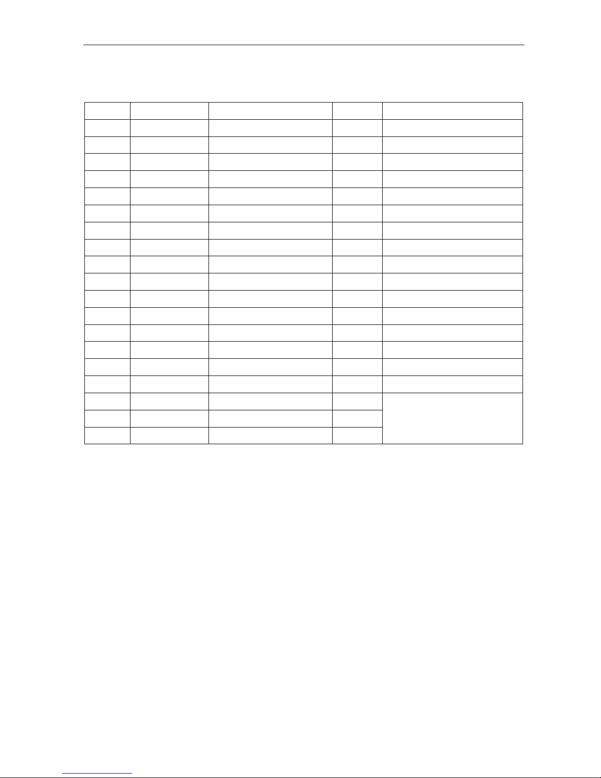
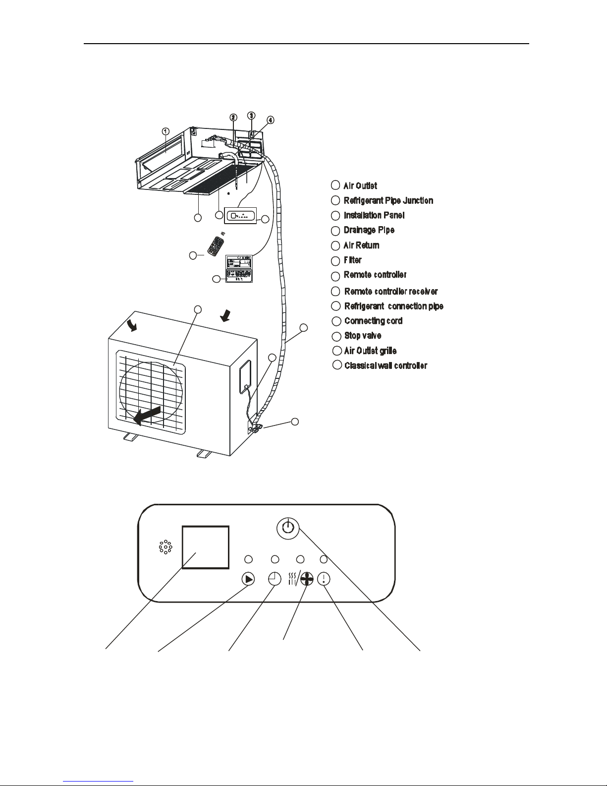
9. Names of parts
Wall split type
Display
Indoor unit
No.
Name
1
Front panel
2
Air filter
3
Special filter(option)
4
Display PCB
5
Vertical vane
6
Horizontal vane
7
Remote controller
Outdoor unit
No.
Name
8
Air outlet grille
9
Electronic box cover
10
2-way valve
11
3-way valve
No.
Name
1
Power
2
Sleep
3
Temperature display
4
Timer
5
Run
1
2-3
4
6
5
7
INDOOR UNIT
8
9
10
11
OUTDOOR UNIT
Page 39

Air Conditioner Service Manual
38
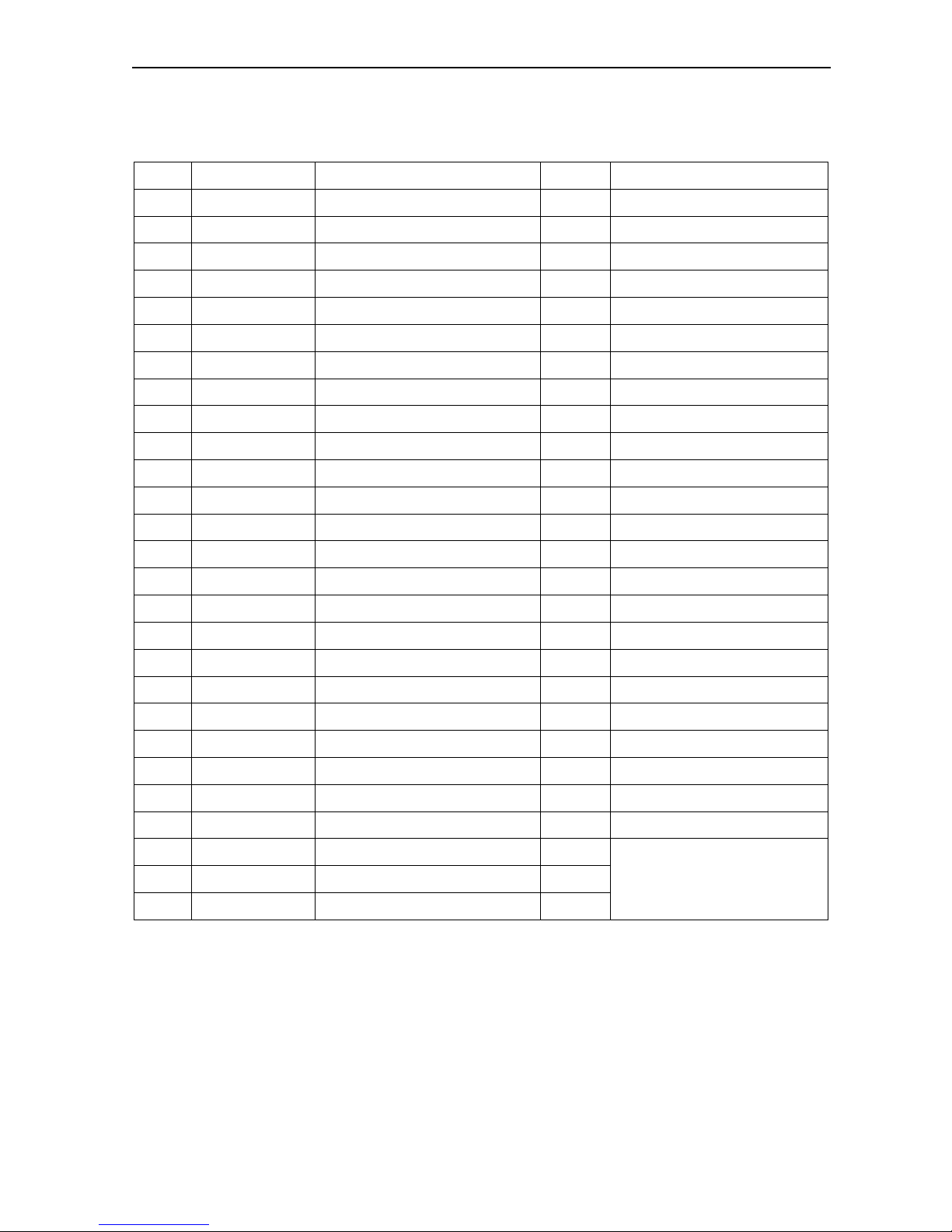
Cassette type
1
2
3
4
5
6
7
8
12
11
10
Outdoor Unit
9
10
12
11
7
8
9
Indoor Unit
13
13
6
3
1
2
4
5
Display
LI GHTING ON
T im er ind icato r
Ope ration indi cat or
PRE -D EF in dic at or
Pum p indica t or
INFRA RE D SIGNAL
REC EI VER
O N when pres et time fo r switching ON /OF F the unit
ON when the uni t is power on
ON when the water lev el is high
ON when the uni t prevent cool air flowing in room.
Time r indica to r
Ope ration ind icat or
PRE-D EF indic at or
Pump indi c ator
Page 40
Air Conditioner Service Manual
39
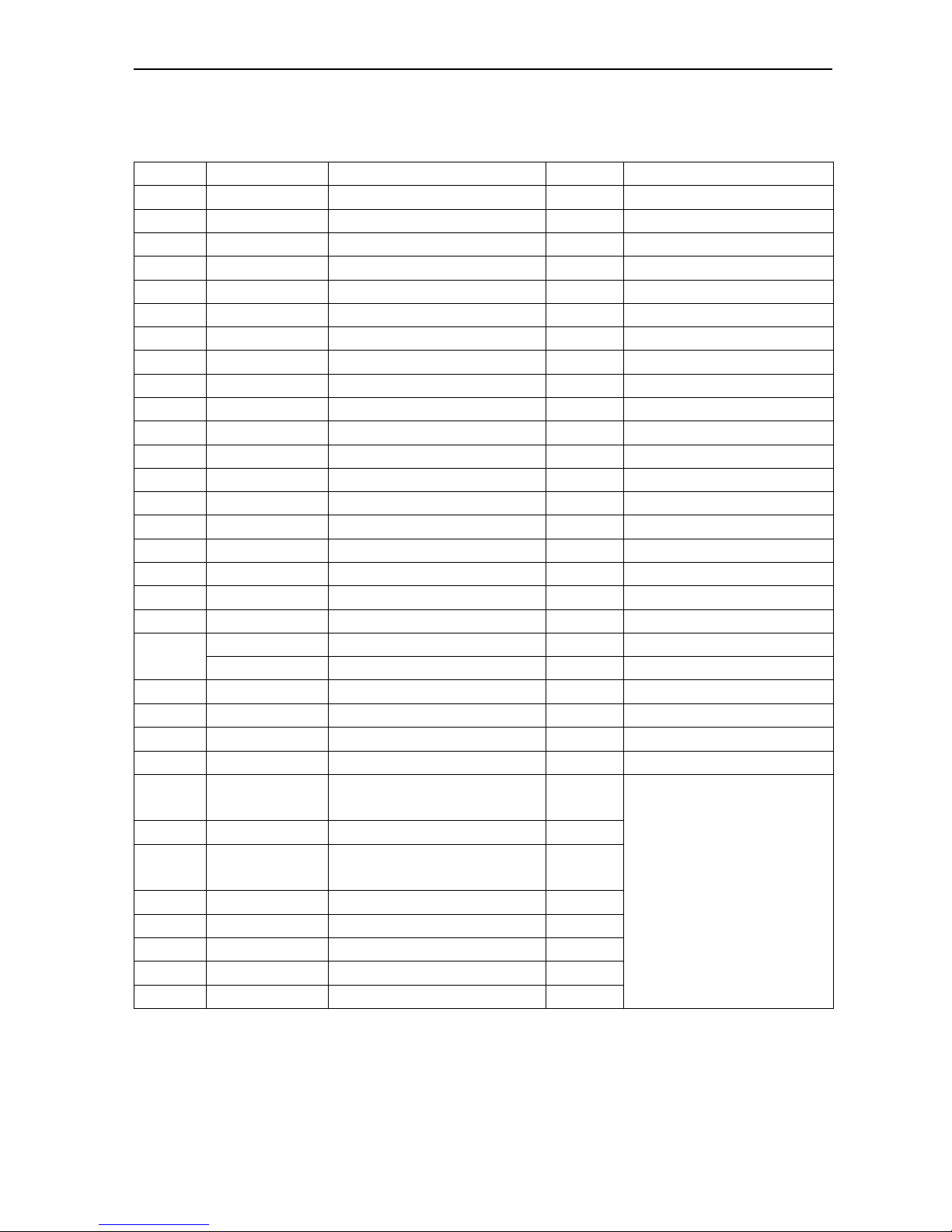
Duct type
1
2
3
4
5
6
7
8
12
11
10
Outdoor Unit
9
10
12
11
6
7
8
5
9
Indoor Unit
13
13
DISPLAY
Manual Switch
Nixie tube Running light Timing light
Defrosting/
preheat light
warning light
Page 41
Air Conditioner Service Manual
40
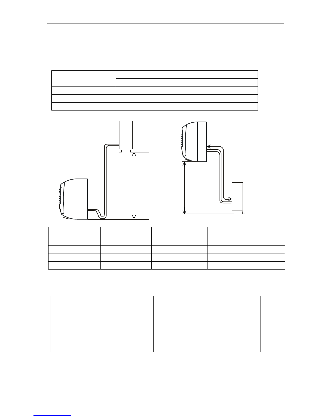
10. Installation manual
10.1 Installation Details
Connecting pipe length
Model
Pipe size(Inch)
Liquid
Gas
9K
1/4
3/8
12K
1/4
3/8
18K
1/4
1/2
Mode
Standard length: m
Refrigerant piping
Max. length: m
Additional refrigerant
Calculation: ×g=20g/m(A-5m)
9K
5.0
20
15g/m
12K
5.0
20
15g/m
18K
5.0
20
20g/m
Connecting cables
The power cord should be selected according to the following specifications sheet.
Appliance Amps
Wire Size
5
AWG21/0.75 mm2
10
AWG18/1.0 mm2
13
AWG15 /1. 5 mm2
18
AWG14/1.6 mm2
25
AWG12/2.0 mm2
30
AWG10/2.5 mm2
Outdoor unit
In door unit
Pipe length is
20 meters Max.
be less than 10m
Height should
Outdoor unit
Indoor unit
Pipe length is
20 meters Max.
be less than 10m
Height should
Page 42

Air Conditioner Service Manual
41
10.2 Installation for the first time
Indoor unit
Wall type:
Install the indoor unit level on a strong wall that
is not subject to vibrations
The inlet and outlet ports should not be
obstructed: the air should be able to blow all over
the room.
Do not install the unit near a source of heat,
steam, or flammable gas.
Install the unit near an electric socket or private
circuit.
Do not install the unit where it will be exposed
to direct sunlight.
Install the unit where connection between indoor
and outdoor unit is as easy as possible.
Install the unit where it is easy to drain the
condensed water.
Check the machine operation regularly and
leave the necessary spaces as shown in the
picture.
Install the indoor unit where the filter can be
easily accessible.
Install the indoor unit in the room to be air
conditioning, avoiding to installation in corridors
or communal areas.
Install the indoor unit at a height of at least 2.5m
from the ground.
Cassette type:
Be sure to lead the refrigerant pipes, drain
pipes and connection wires out to its
connection location before hanging the unit if
the opening on the ceiling has been decided.
Confirm sizes of the indoor unit and ceiling opening
with the attached installation paper pattern. (Please
fix the paper pattern below the body with M5X16
screws (4).
Duct
OUTDOOR UNIT
Do not install the outdoor unit near sources of
heat, steam or flammable gas.
Do not install the unit in too windy or dusty
places.
Do not install the unit where people often
pass. Select a place where the air discharge
and operating sound level will not disturb the
neighbours.
Avoid installing the unit where it will be exposed
to direct sunlight (other wise use a protection, if
necessary, that should not interfere with the air
flow).
Leave the spaces as shown in the picture for
The air to circulate freely.
Install the outdoor unit in a safe and solid place.
If the outdoor unit is subject to vibration, place
rubber gaskets onto the feet of the unit.
Minimum space to be left (mm) showing in the
picture.
Wall
material
Flammable
material
Fire-proof or
nonflammable
materials
Fire-proof
structure
B
Above 5cm
Above 5cm
Above 5cm
C
Above 100cm
Above 100cm
-
condensed water drain pipe
150mm
150mm
150mm
Sleeve
insulating covering
electrical cable
Mounting plate
water drain pipe
A>330mm
B
C
Air outlet side
100mm
Canvas tunnel
00
Page 43

Air Conditioner Service Manual
42
To install, proceed as follows:
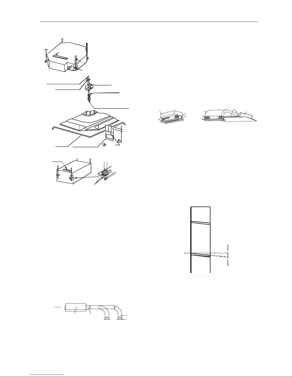
10.2.1 Installation of the mounting plate.
Wall split type:
1) By using a level, put the mounting plate in a
perfect square position vertically and horizontally.
2) Drill 32mm deep holes in the wall to fix the plate.
3) Insert the plastic anchors into the hole.
4) Fix the mounting plate by using the provided
tapping screws.
5) Check that the mounting plate is correctly fixed.
Note: The shape of the mounting plate may be
different from the one above, but installation
method is similar.
Cassette and Duct type:
Wooden construction
Put the square timber over the roof beam, then install the
hanging screw bolts.
Timber over the beam
Roof beam
Hanging Screw
Ceili ng
Bol t
For finished concrete bricks
Install the hanging hook with expansible bolt into the
concrete deep to 45~50mm to prevent loose.
New Concrete Bricks
Inlaying or embedding the screw bolts.
(Blade shape (Slide insertion)
insertion)
(Pipe hanging and embedding screw bolt)
Steel roof beam structure
Install the supporting angle steel.
Overhanging the indoor unit
Adjust the gasket (down side) to 90mm over the
ceiling.
Install the hanging bolt into T groove of the hanging
tool. Overhang the indoor unit and ensure it is level
using a level indicator.
300mm
500mm
2000mm
300mm
500mm
Steel bar
Embedding screw bolt
Hanging screw bolt
Hanging bolts
Supporting
angle steel
Hanging Bolt
Nut (Up Side)
Gasket (Up Side)
Installing Ear
Nut (Down Side)
Down sid e of the ceiling
Gasket (Down Side)
90mm
Page 44
Air Conditioner Service Manual
43
cassette
Duct
How to mount outlet pipe.
Generally, we have two types of outlet pipe
available, i.e. rectangular or round ones.
Rectangular air conduit can be directly
connected to air outlet of indoor unit by rivets.
For outlet dimensions, see outline drawing of
the unit.
Round air conduit should be connected to a
piece of transitional air conduit before it is
connected to air outlet of indoor unit, the other
end of it can be separately connected to air
conduit window or connected to air conduit
window after air flow diversion, and the total
length should not be over 6m. As shown in
figure below, air speeds at all air outlets should
be set to basically consistent so as to meet the
room air-conditioning requirements.
Installation method for return air pipe
In case sidewise air intake is adopted, return
air pipe should be fabricated and rivetconnected to return air orifice, and the other
end of it should be connected to return air
window.
In case of underside air intake, purchase or
fabricate a section of pleated canvas air
conduit serving as transition joint for return air
orifice and return air window. in this way, it can
be freely adjusted according to height of indoor
ceiling board; in addition, during operation of
the unit , canvas air conduit may avoid
vibration of ceiling board, as shown in figure
below.
10.2.2 Drilling a hole in the wall for the piping
1) Decide where to drill the hole in the wall for the
piping (if necessary) according to the position of
the mounting plate
2) Install a flexible flange through the hole in the
wall to keep the latter intact and clean.
The hole must slope downwards towards the
exterior.
Note: Keep the drain pipe down towards the
direction of the wall hole, otherwise leakage may
occur.
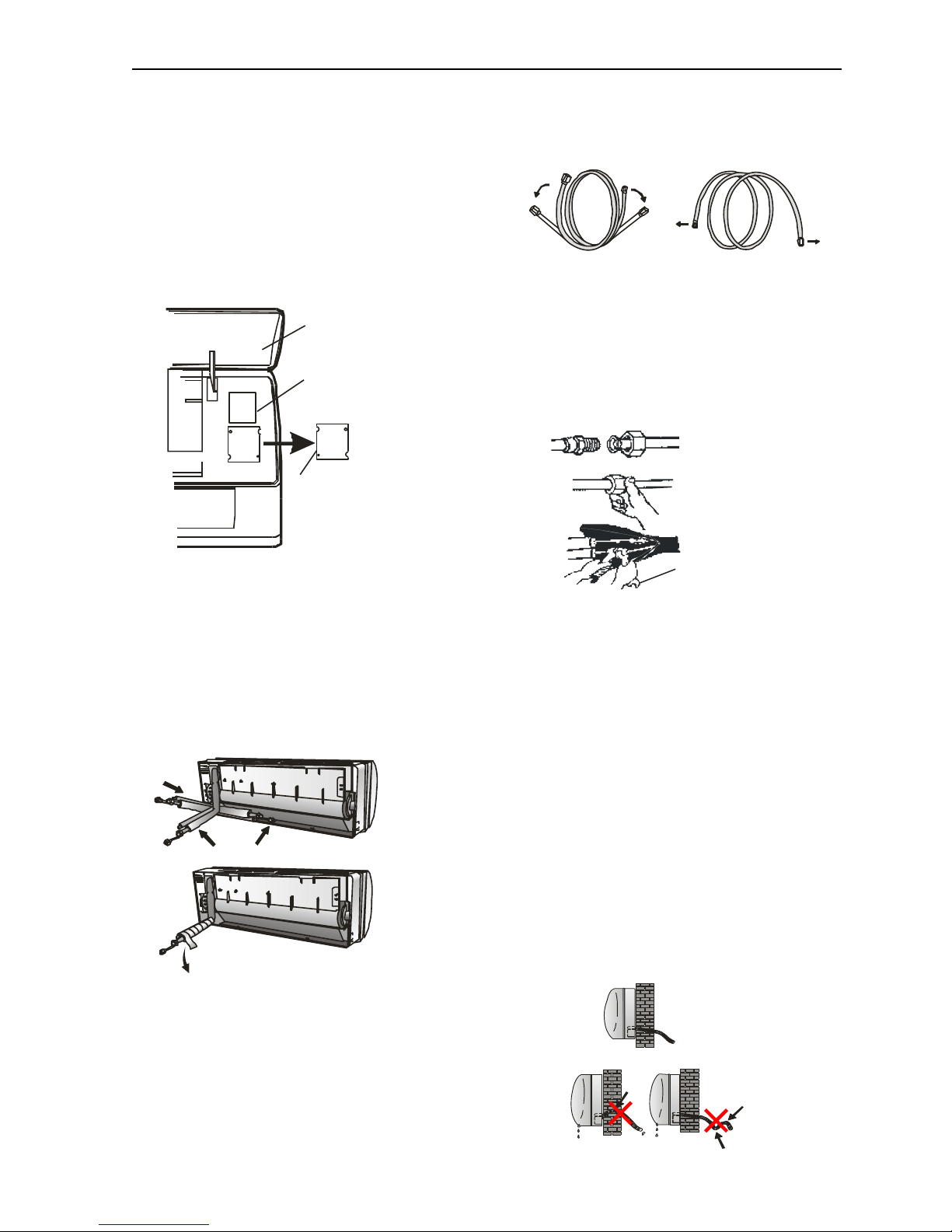
10.2.3 Electrical connections---Indoor unit
1).Lift the front panel.
2).Take off the cover as indicated in the picture
(by removing a screw or by breaking the hooks).
3).For the electrical connections, see the circuit
diagram on the right part of the unit under the
front panel.
4).Connect the cable wires to the screw terminals
by following the numbering, Use wire size
suitable to the electric power input (see name
plate on the unit) and according to all current
national safety code requirements.
5mm
Indoors
Outdoors
Tighten nut M10
Le vel Indicator
Han ging Screw Bolt
Hanging Screw Bolt M10
Install it down the
installing-ear
Locking Nut M10
Hanging Ear
1 0 G asket
Indoor Unit
Ceiling
Installation Plate
30mm
43mm
Must Be Fixed Tight
Gradienter
In door u nit
Air -outl et wi ndow
Ou tlet p ipe
Tran sition al a ir
co nduit
Air inlet
Installation mode for sidewise air intake
Unit
Canvas air conduit
Return air pipe
Return air window
Rivet
Unit
Return air pipe
Canvas air conduit
Rivet
Page 45
Air Conditioner Service Manual
44
5).The cable connecting the outdoor and indoor
units must be suitable for outdoor use.
6).The plug must be accessible also after the
appliance has been installed so that it can be
pulled out if necessary.
7).An efficient earth connection must be
ensured.
8).If the power cable is damaged, it must be
replaced by an authorized Service Centre.
10.2.4 Refrigerant piping connection
The piping can be run in the 3 directions indicated
by numbers in the picture. When the piping is run
in direction 1 or 3, cut a notch along the groove on
the side of the indoor unit with a cutter.
Run the piping in the direction of the wall hole and
bind the copper pipes, the drain pipe and the
power cables together with the tape with the drain
pipe at the bottom, so that water can flow freely.
10.2.5 Connecting the pipes.
Do not remove the cap from the pipe until
connecting it, to avoid dampness or dirt
from entering.
If the pipe is bent or pulled too often, it will
become stiff. Do not bend the pipe more
than three times at one point.
When extending the rolled pipe, straighten
the pipe by unwinding it gently as shown in
the picture.
10.2.6 Connections to the indoor unit
1).Remove the indoor unit pipe cap (check that
there is no debris inside).
2).Insert the fare nut and create a flange at the
extreme end of the connection pipe.
3).Tighten the connections by using two wrenches
working in opposite directions.
10.2.7 Indoor unit condensed water drainage
The indoor unit condensed water drainage is
fundamental for the success of the installation.
1).Place the drain hose below the piping, taking
care not to create siphons.
2).The drain hose must slant downwards to aid
drainage.
3).Do not bend the drain hose or leave it protruding
or twisted and do not put the end of it in water.
If an extension is connected to the drain hose,
ensure that it is lagged when it passes into the
indoor unit.
4).If the piping is installed to the right, the pipes,
power cable and drain hose must be lagged and
secured onto the rear of the unit with a pipe
connection.
Insert the pipe connection into the relative slot.
Press to join the pipe connection to the base.
Front panel
Terminal block cover
Wiring diagram
3
2
1
Shape the connection pipe
NO
YES
Extending the rolled pipe
torque wrench
YES
NO NO
Page 46
Air Conditioner Service Manual
45
For Cassette and Duct type
The drain pipe of indoor unit must have the
heat insulation , or it will condense dew, as
well as the connections of the indoor unit.
The declivity of the drain pipe downwards
should not be over 1/100, and no winding and
bending.
The total length of the drain pipe when pulled
out traversely shall not exceed 20m , when the
pipe is over long, a prop stand must be
installed every 1.5 to 2m to prevent winding.
Refer to the following figures about the
installation of the pipes.
Do not impose any pressure on the connection
part of the drainage pipe.
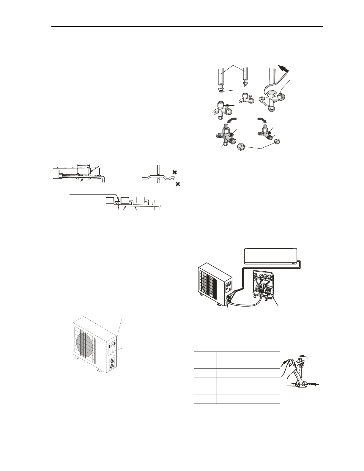
10.2.8 Electronic connections of outdoor unit
1. Take the cover away.
2. Connect the cable wires to the terminal board
using the same numbering as in the indoor unit.
3. For the electrical connections, see the wiring
diagram on the back of the cover
4. Fasten the cables with a cable-clamp.
5. An efficient earth connection must be ensured.
6. Replace the covers.
Wiring diagram on the back of the cover
Screw
Remove the upper cover
Outdoor unit
10.2.9 Connecting the pipe of outdoor unit
Screw the flare nuts to the outdoor unit coupling
with the same tightening procedures described for
the indoor unit.
Note: If the tightening torque is not sufficient, there
will probably be some leakage. With excessive
tightening torque there will also be some leakage,
as the flange could be damaged.
10.2.10 Bleeding
Air and humidity left inside the refrigerant circuit can
cause compressor malfunction. After having
connected the indoor and outdoor units, bleed the
air and humidity from the refrigerant circuit by using
a vacuum pump.
The air and humidity left inside the refrigerant
circulation can cause compressor malfunction.
After having connected the indoor and outdoor
units, bleed the air and humidity from the
refrigerant circulation using a vacuum pump.
Notice
According to installation conditions, overlarge
wrenched Torch will destroy the nut. (Unit. N.cm)
Pipe
Tightening
torque(N.M)
1/4’’
15-20
3/8’’
31-35
1/2’’
35-45
5/8’’
75-80
connection pipes
flare nuts
liquid tap
gas tap
indoor unit
protection caps
Liquid valve
gas valve
service port nut
tap
vacuum pump
service port
VP30
Suppor t
Bend
Up and Down
Fold
As long as pos sib le a bout (10mm )
Le an Dow nwa rd
over 1/10 0
1.5m~2m
L ean Downward ov er 1/100
Page 47

Air Conditioner Service Manual
46
11. Trouble shooting
11.1 Outdoor control diagram
11.2 The structure of ODU PCB
ONE TO 2 TYPE
Motor
Communication
Filter circuit for
heavy current
Switch power supply
LP HP
Communication
Communication
Sensor
circuit
Expansion
valve
4-way valve
Compressor
driving
Rectifying filtering
circuit
PFC
EEPROM
Switch power supply
Communication
LP HP
Page 48

Air Conditioner Service Manual
47
ONE TO 3/4 TYPE:
11.3 Examples of repairing
11.3.1 Display E1 or E2
Reasons:
1) The sensor connection terminal loose or not plugged in.
Wall type
Cassette type/Duct type
Solution: Check the connecter of sensor and slot (CN6, CN6-1, CN6-2), if loose or not plugged in,
please connect again.
2) Room temperature sensor (IRT) and Indoor pipe (coil) temperature sensor (IPT) damage (short or
broken).
Solution: check the resistance of the sensor wall type R (25℃) =5 kΩ, cassette and duct type R
(25℃) =5 kΩ, if short or broken please replace it.
Expansion
valve
Sensor
circuit
LP HP
Motor
Compressor
driving
Switch power supply
Communication
Filter circuit for
heavy current
Rectifying filtering
circuit
4-Way valve
EEPROM
Page 49

Air Conditioner Service Manual
48
3) The PCB fail.
Solution: Replace the indoor main PCB.
11.3.2 Display E6
Reasons:
1) The indoor motor connection terminal loose or not plugged in.
Solution: Check the connecter of indoor motor and slot (CN3) and (CN4), if loose or not plugged in, please
connect again.
2) The indoor motor damage.
Solution: Check and replace the motor.
3) The indoor main PCB damage.
Solution: Replace the indoor main PCB.
OK
Fail
Page 50

Air Conditioner Service Manual
49
11.3.3 Display E3, E7
Reasons:
1) Outdoor pipe temp sensor, outdoor temp sensor & exhaust temp sensor connection terminal loose or not
plugged in.
Solution: Check the connecter of sensor and slot, if loose or not plugged in, please connect again.
2) Outdoor pipe temp sensor, outdoor temp sensor & exhaust temp sensor damage (short or broken).
Solution: Check and replace the sensor.
3) Outdoor PCB damage.
Solution: Check and replace the outdoor PCB.
11.3.4 Display E8
Reasons:
1) Outdoor discharge pipe temp sensor connection terminal loose or not plugged in.
Solution: Check the connecter of sensor and slot, if loose or not plugged in, please connect again.
2) Outdoor pipe temp sensor damage.
Solution: Check and replace the sensor.
3) Outdoor PCB damage.
Solution: Check and replace the outdoor PCB.
11.3.5 Display E0,E5
Reason: Indoor / outdoor communication damage.
Solution:
1) Check if the indoor and outdoor connections are correct. The terminal L and N which connect to indoor
unit shall correspond to each other on indoor and outdoor units. Measure the voltage on outdoor
Fail
OK
Fail
OK
Page 51

Air Conditioner Service Manual
50
terminal L and N (before display of E0 fault). If the voltage is “0”, please replace indoor main PCB.
2) If the 1 & N which connect to indoor unit voltage is normal, measure the voltage between the outdoor
terminal 1A, 1B, 1C, 1D and N. If the voltage change occurs between 0~24V (change pulse voltage),
please replace indoor main PCB.
3) If the 1A, 1B, 1C, 1D & N which connect to indoor unit voltage is normal, measure the voltage between
the outdoor terminal 1 and N. If the voltage change occurs between 0~12V( change pulse voltage), but
there is no 24V, please replace the outdoor PCB.
4) If the 1, 1A, 1B, 1C, 1D & N voltage is normal, measure the voltage between the outdoor terminal 1
and N. If the voltage has no change, firstly replace the indoor main PCB. If the fault remains
unsolved, replace the outdoor PCB.
5) Communication fault if resistance or optical coupler broken, replace outdoor PCB.
Is there any burnt on PCB? If no, test the rectifier, FRD, IGBT etc. any component broken, replace PCB.
Communication
circuit
Page 52

Air Conditioner Service Manual
51
6) Test the DC voltage between DC+ and DC-. If the voltage is less than 50V approximately, please
replace outdoor PCB.
11.3.6 Display EA
Reason: Current sensor fault.
Solution:
1) Check for refrigerant leakage, to find the leakage point and recharge the refrigerant.
2) Current sampling circuit broken on the outdoor PCB and replace outdoor PCB.
11.3.7 Display E9(first display P0 or P9)
Reason: Outdoor PCB drive circuit damage.
Solution:
Re-energize and check the protection code on display. Firstly display P0.
1) If this code is displayed when the compressor is started for several seconds or even not started, check
the compressor connection for correctness, if no insert wrong, replace outdoor PCB.
2) Check if the outdoor module is tightly installed onto the radiating fins and if the silicone is applied
evenly, fix the screws again if loose.
Any of 2 pins should be
no short circuit
Any of 2 pins should be
no short circuit
Any of 2 pins should be
no short circuit
DC-
DC
+
Current sampling
circuit
Compressor connection
Page 53

Air Conditioner Service Manual
52
3) Check the system pressure, recharge refrigerant if the pressure is low, and discharge some
refrigerant if the pressure is too high.
4) Check the outdoor ventilation and if there is any obstruction that affects the normal radiating of the air
conditioner, and installation again.
5) If the above inspections are normal, but the fault remains unsolved, please replace the outdoor PCB.
Re-energize and check the protection code on display. Firstly display P9.
a) Check the U,V, W connection, if is correctness or loose please connect again.
b) If this code is displayed when the compressor is started for several seconds or even not started,
check the compressor connection for correctness, if no insert wrong, replace outdoor PCB.
11.3.8 Display EU.
Reason: Voltage sensor damage.
Solution: Please replace outdoor PCB.
11.3.9 Display EE
Reason: EEPROM fault.
Solution: Shut down power supply and reenergize it, if the fault remains there, check the EEPROM
installation, if no problem, please replace outdoor PCB.
11.3.10 Display CL
Cause: Air filter duty, the unit operation Cumulative time 500 hours, the controller will confirmation the filter
dirty and display CL.
Solution: Clean the air filter then cut off the power and supply again.
Fixing screw
U, V, W connection
Heat radiation problem easily happened
while the screw is not fixed tightly.
Voltage sensor
EEPROM
Page 54

Air Conditioner Service Manual
53
11.4 MALFUNCTION (PARTS) CHECK METHOD
11.4.1 Procedure for determining defective outdoor unit IPM/compressor
The following flow chart shows a procedure for locating the cause of a malfunction when the compressor
does not start up and a DC overcurrent indication error occurs.
Clean indoor or outdoor
heat exchange
Clean indoor heat exchange
and outdoor heat exchange
Check the refrigerant
amount
Check the installation condition
Installation again
P9
Use the remote operates
the air conditioner
Does compressor start up
No
Does the wire
connects right
No
Connects wire
again
Yes
Open
Does low or high press
valve opened
Operates again after 3 Mins
Yes
Yes
No
Compressor star up
Yes
Does indoor unit LED
display error code.
Normal
No
Replace the
inverter PCB
Normal
Yes
No
Replace the compressor
P0
Does compressor start
Does the wire
connects right
Connects wire
again
Replace the inverter PCB
Normal
No
Yes
Normal
Normal
Add gas
Not enough
Page 55

Air Conditioner Service Manual
54
11.4.2 DC Over Current Error
Error memory is
Start
Are valves (2-way
or 3-war) close?
Full open stop valves
Does compressor
rotates?
Does compressor
rotates more than
30 seconds?
Check IPM lead
wire (UVW)
Is IPM PWB floating
from the heat sink?
Fix IPM PWB with screws
securely.
Check the AC power
supply voltage when
compressor rotate.(rated
voltage±10%)
Check IPM short
circuit.
Modify the connection of
compressor lead wire on
PWB
Replace PWB.
Cooling mode?.
Check compressor
Modify compressor terminal
marking
Replace PWB
Does compressor
rotates?
Replace compressor
Check indoor
exchange sensor
and discharge
sensor
Modify or replace
the sensor.
Check outdoor
exchange sensor
and discharge
sensor
Modify or replace
the sensor.
Check indoor
heat exchange.
Check outdoor
heat exchange
Clean indoor heat
exchange
Clean outdoor
heat exchange
Check the refrigerant
amount
Check the discharge
press
Check the installation
condition
Yes
Yes
No
No
No
No
Yes
Yes
Abnormal
Abnormal
Abnormal
Normal
Normal
Normal
Normal
Normal
Normal
No
Yes
Abnormal
Abnormal
Abnormal
Abnormal
Normal
Page 56

Air Conditioner Service Manual
55
11.4.3 E0,E5 Error
Start
Display E0
Shut off power and supply
again and observe 10 Mins
Check the wire
connections
Replace power supply
board or outdoor PCB
assembly
If the voltage change
occurs between
0~12V not 13~24V
Display E5
Display E0
Check the terminal
L and N voltage
OK
Connects the
wire again
Replace indoor
PCB
Not OK
Yes
Shut off power
and supply again
Display E5
Replace inverter board and power
supply board or outdoor PCB
assembly
Display E5
Replace inverter board
Display E0 first and then
display E5 and keep
If the indicator on the
outdoor PCB blink?
Check terminal L&N
voltage
Yes
No
Check the rectifier
bridge, fast recovery
diode (FRD) and IGBT
Solve as E0
Check wire connected
and replace indoor PCB
Normal
Abnormal
Replace PFC board or
outdoor PCB assembly
Test the DC voltage
between DC+ and DC-
Damage
Normal
If the voltage is
approx. 300V
If the voltage is
approx. zero
Replace power supply
board or outdoor PCB
assembly
Replace PFC board
or outdoor PCB
assembly
If the problem cannot be solved
by using the methods above
Replace the indoor main PCB,
power source board, and PFC
board or outdoor PCB assembly
If the voltage is
0 V
If the voltage
change occurs
between 0~24V
Check the terminal
N and 1 voltage
No
Replace indoor
PCB
Yes
If the voltage no change
Replace indoor PCB, if
unsolved replace power
supply board or outdoor
PCB assembly
Yes
Page 57

Air Conditioner Service Manual
56
11.5 THERMISTOR TEMPERATURE CHARACTERISTICS
1. Indoor unit and outdoor exchange temperature and outside air temperature sensor temperature
characteristics
TEMP.
(℃)
Resistance
(k Ohm)
Voltage of
resistance
TEMP.
(℃)
Resistance
(k Ohm)
Voltage of
resistance
TEMP.
(℃)
Resistance
(k Ohm)
Voltage of
resistance
-30
63.513
4.628
15
7.447
2.968
60
1.464
1.115
-29
60.135
4.609
16
7.148
2.918
61
1.418
1.088
-28
56.956
4.589
17
6.863
2.868
62
1.374
1.061
-27
53.963
4.568
18
6.591
2.819
63
1.331
1.035
-26
51.144
4.547
19
6.332
2.769
64
1.290
1.009
-25
48.488
4.524
20
6.084
2.720
65
1.250
0.984
-24
45.985
4.501
21
5.847
2.671
66
1.212
0.960
-23
43.627
4.477
22
5.621
2.621
67
1.175
0.936
-22
41.403
4.452
23
5.404
2.572
68
1.139
0.913
-21
39.305
4.426
24
5.198
2.524
69
1.105
0.890
-20
37.326
4.399
25
5.000
2.475
70
1.072
0.868
-19
35.458
4.371
26
4.811
2.427
71
1.040
0.847
-18
33.695
4.343
27
4.630
2.379
72
1.009
0.825
-17
32.030
4.313
28
4.457
2.332
73
0.979
0.805
-16
30.458
4.283
29
4.292
2.285
74
0.950
0.785
-15
28.972
4.252
30
4.133
2.238
75
0.922
0.765
-14
27.567
4.219
31
3.981
2.192
76
0.895
0.746
-13
26.239
4.186
32
3.836
2.146
77
0.869
0.728
-12
24.984
4.152
33
3.697
2.101
78
0.843
0.710
-11
23.795
4.117
34
3.563
2.057
79
0.819
0.692
-10
22.671
4.082
35
3.435
2.012
80
0.795
0.675
-9
21.606
4.045
36
3.313
1.969
81
0.773
0.658
-8
20.598
4.008
37
3.195
1.926
82
0.751
0.641
-7
19.644
3.969
38
3.082
1.883
83
0.729
0.625
-6
18.732
3.930
39
2.974
1.842
84
0.709
0.610
-5
17.881
3.890
40
2.870
1.800
85
0.689
0.595
-4
17.068
3.850
41
2.770
1.760
86
0.669
0.580
-3
16.297
3.808
42
2.674
1.720
87
0.651
0.566
-2
15.565
3.766
43
2.583
1.681
88
0.633
0.552
-1
14.871
3.723
44
2.494
1.642
89
0.615
0.538
0
14.212
3.680
45
2.410
1.604
90
0.598
0.525
1
13.586
3.635
46
2.328
1.567
91
0.582
0.512
2
12.991
3.590
47
2.250
1.530
92
0.566
0.499
3
12.426
3.545
48
2.174
1.495
93
0.550
0.487
4
11.889
3.499
49
2.102
1.459
94
0.535
0.475
5
11.378
3.452
50
2.032
1.425
95
0.521
0.463
6
10.893
3.406
51
1.965
1.391
96
0.507
0.452
7
10.431
3.358
52
1.901
1.357
97
0.493
0.441
8
9.991
3.310
53
1.839
1.325
98
0.480
0.430
9
9.573
3.262
54
1.779
1.293
99
0.467
0.419
10
9.174
3.214
55
1.721
1.262
100
0.455
0.409
11
8.795
3.165
56
1.666
1.231
12
8.433
3.116
57
1.613
1.201
13
8.089
3.067
58
1.561
1.172
14
7.760
3.017
59
1.512
1.143
Page 58
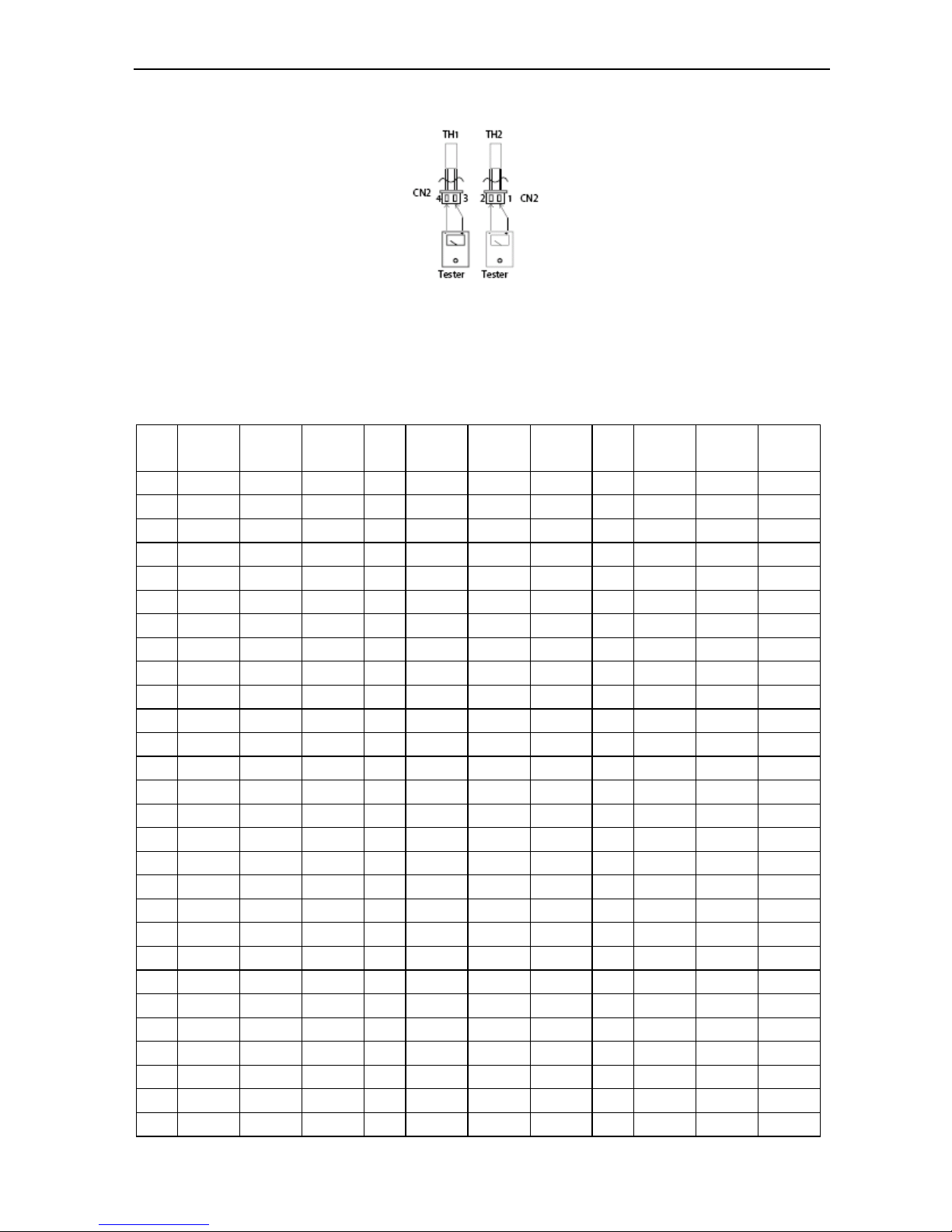
Air Conditioner Service Manual
57
Resistance at 25℃: wall split type 5 kΩ, cassette and duct 10kΩ.
TH1: indoor room temperature sensor and outside air temperature sensor
TH2: indoor exchange temperature sensor and outside exchange temperature sensor
Before measuring resistance, disconnect connectors as shown above.
2. Outdoor unit sensor temperature characteristics
TEMP
(℃)
R min
(k Ohm)
R(t)
(k Ohm)
R max
(k Ohm)
TEMP.
(℃)
R min
(k Ohm)
R(t)
(k Ohm)
R max
(k Ohm)
TEMP.
(℃)
R min
(k Ohm)
R(t)
(k Ohm)
R max
(k Ohm)
-30
283.3
322.9
367.7
24
19.36
20.89
22.52
78
2.563
2.654
2.745
-29
267.4
304.4
346.3
25
18.55
20
21.54
79
2.481
2.567
2.654
-28
252.5
287.1
307.4
26
17.77
19.14
20.6
80
2.402
2.484
2.567
-27
238.5
270.9
307.4
27
17.03
18.32
19.7
81
2.327
2.404
2.483
-26
225.4
255.7
289.8
28
16.32
17.55
18.85
82
2.254
2.327
2.401
-25
213.1
241.4
273.3
29
15.65
16.81
18.04
83
2.183
2.253
2.323
-24
201.5
228
257.9
30
15
16.1
17.27
84
2.115
2.182
2.248
-23
190.6
215.5
243.4
31
14.39
15.43
16.54
85
2.05
2.113
2.176
-22
180.3
203.6
229.8
32
13.81
14.79
15.34
86
1.985
2.047
2.109
-21
170.7
192.5
217
33
13.25
14.18
15.17
87
1.922
1.983
2.045
-20
161.6
182.1
205
34
12.72
13.6
14.54
88
1.861
1.922
1.983
-19
153.1
172.3
193.7
35
12.21
13.05
13.93
89
1.802
1.862
1.923
-18
145
163.1
183.2
36
11.72
12.52
13.36
90
1.746
1.805
1.865
-17
137.5
154.4
173.2
37
11.26
12.01
12.81
91
1.692
1.75
1.809
-16
130.3
146.2
163.9
38
10.82
11.53
12.29
92
1.639
1.697
1.755
-15
123.6
138.5
155.1
39
10.29
11.07
11.78
93
1.589
1.646
1.703
-14
117.3
131.3
146.8
40
9.986
10.63
11.31
94
1.54
1.596
1.653
-13
111.3
124.4
139
41
9.6
10.21
10.85
95
1.493
1.549
1.604
-12
105.6
118
131.7
42
9.231
9.813
10.42
96
1.448
1.502
1.558
-11
100.3
111.9
124.7
43
8.878
9.43
10
97
1.404
1.458
1.512
-10
95.24
106.2
118.2
44
8.54
9.064
9.612
98
1.362
1.415
1.469
-9
90.49
100.8
112.1
45
8.217
8.714
9.233
99
1.321
1.373
1.426
-8
85.99
95.68
106.3
46
7.908
8.38
8.872
100
1.284
1.335
1.387
-7
81.75
90.86
100.8
47
7.612
8.06
8.526
101
1.245
1.296
1.348
-6
77.74
86.31
95.74
48
7.328
7.754
8.196
102
1.209
1.258
1.309
-5
73.94
82.01
90.88
49
7.057
7.461
7.88
103
1.173
1.222
1.272
-4
70.35
77.95
86.29
50
6.797
7.18
7.578
104
1.139
1.187
1.236
-3
66.96
74.11
81.96
51
6.548
6.912
7.289
105
1.105
1.153
1.202
Page 59

Air Conditioner Service Manual
58
-2
63.74
70.48
77.87
52
6.309
6.655
7.013
106
1.073
1.12
1.168
-1
60.69
67.05
74
53
6.08
6.409
6.748
107
1.042
1.089
1.136
0
57.81
63.8
70.34
54
5.861
6.173
6.495
108
1.013
1.058
1.104
1
55.08
60.72
66.88
55
5.651
5.947
6.253
109
0.9833
1.028
1.074
2
52.49
57.81
63.61
56
5.449
5.73
6.02
110
0.9553
0.9997
1.045
3
50.03
55.05
60.52
57
5.255
5.522
5.798
111
0.9283
0.9719
1.016
4
47.71
52.44
57.59
58
5.07
5.323
5.585
112
0.9021
0.9451
0.9892
5
45.5
49.97
54.82
59
4.891
5.132
5.381
113
0.8765
0.9191
0.9626
6
43.41
47.62
52.2
60
4.72
4.949
5.101
114
0.8524
0.894
0.9367
7
41.42
45.4
49.71
61
4.556
4.774
4.997
115
0.8087
0.8595
0.9117
8
39.53
43.2
42.33
62
4.398
4.605
4.817
116
0.8059
0.8461
0.8875
9
37.74
41.29
45.12
63
4.247
4.448
4.644
117
0.7837
0.8233
0.8641
10
36.04
39.39
43.01
64
4.101
4.288
4.479
118
0.7623
0.8012
0.8413
11
34.42
37.59
41
65
3.961
4.139
4.32
119
0.7415
0.7798
0.8193
12
32.89
35.87
39.1
66
3.827
3.995
4.167
120
13
31.43
34.25
37.29
67
3.698
3.858
4.021
121
0.702
0.7386
0.7773
14
30.04
32.71
35.58
68
122
0.6631
0.7195
0.7572
15
29.72
31.24
33.95
69
123
0.6649
0.7007
0.7378
16
70
3.339
3.476
3.616
124
0.6472
0.6824
0.7189
17
71
3.229
3.359
3.491
125
0.6301
0.6647
0.7006
18
25.13
27.26
29.55
72
3.122
3.246
3.372
126
0.6135
0.6476
0.6829
19
24.05
26.07
28.23
73
3.02
3.138
3.257
127
0.5974
0.6309
0.6657
20
23.02
24.93
26.97
74
2.921
3.033
3.146
128
0.5818
0.6148
0.649
21
22.04
23.84
25.77
75
2.827
2.933
3.04
129
0.5667
0.5991
0.6328
22
21.1
22.81
24.63
76
2.735
2.836
2.938
130
0.5521
0.5839
0.6171
23
20.21
21.83
23.55
77
2.647
2.743
2.84
R—Resistance
Resistance at 25℃:20 kΩ
TH3: Outdoor unit discharge pipe sensor
Before measuring resistance, disconnect connectors as shown above.
 Loading...