

Page 1
TCL
SERVICE MANUAL
No.TE040427
WALL MOUNTED SPLIT-TYPE AIR CONDITIONERS
Models
TAC-07CS/K TAC-09CS/K
TAC-12CS/K
TAC-18CS/K
TAC-24CS/K TAC-07CHS/K
TAC-09CHS/K TAC-12CHS/K
TAC-18CHS/K TAC-24CHS/K
CONTENTS
1. IMPORTANT NOTICE ···································2
2. TECHNICAL SPECIFICATION ·····················3
3. OPERATION DETAILS ····································6
4. WIRING DIAGRAM ············· 14
5. EXPLOSION VIEW ····························20
6. PARTS LIST ·············28
Page 2

IMPORTANT NOTICE
This service manual is intended for use by individuals possessing adequate
backgrounds of electrical, electronic and mechanical experience. Any
attempt to repair the appliance may result in personal injury and property
damage. The manufacturer or seller cannot be responsible for the
interpretation of this information, nor can it assume any liability in
connection with its use.
The information, specifications and parameter are subject to change due to
technical modification or improvement without any prior notice. The
accurate specifications are presented on the nameplate label.
How to order spare parts
To have your order filled promptly and correctly, please furnish the
following information:
1. Model No. with Indoor or Outdoor
2. No. in the Explosion View
3. Part Name
4. The quantity you ordered
TCL Air Conditioner Service ManualTCL Air Conditioner Service ManualTCL Air Conditioner Service Manual
TCL Air Conditioner Service Manual
2
Page 3
TCL Air Conditioner Service Manual
3
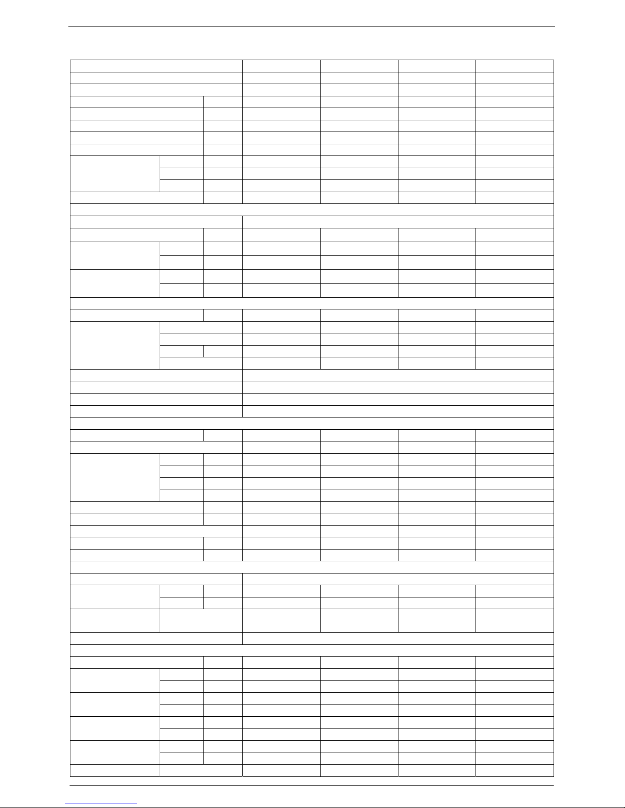
Technical Specifications
Model No. TAC-07CS/K TAC-07CHS/K TAC-09CS/K TAC-09CHS/K
Type Cooling Only Heating Pump Cooling Only Heating Pump
Control type Remote Remote Remote Remote
Rated cooling capacity Btu/h 7,000 7,000 9,000 9,000
Rated heating capacity Btu/h N/A 7,500 N/A 9,500
EER for cooling Btu/h.w 9.6 9.6 9.6 9.6
COP for heating W/W N/A 2.8 N/A 2.8
Moisture removal Liters/h 0.8 0.8 0.8 0.8
High dB(A) 36 36 36 36
Med. dB(A) 32 32 32 32
Indoor noise level at
cooling
Low dB(A) 29 29 29 29
Outdoor noise level dB(A) 50 50 50 50
Electrical Data
Power supply 220-240V~/50Hz
Voltage Range V
Cooling A 4.2 4.2 4.2 4.2
Rated current
Heating A N/A 4.1 N/A 4.1
Cooling W 895 895 900 900
Rated input
Heating W N/A 880 N/A 880
Refrigerating System
Refrigerant/Charge Gram R22/700g R22/700g R22/700g R22/700g
Type Rotary Rotary Rotary Rotary
Model ------------------ ----------------- ------------------ -----------------LRA A ------ ------- ------ ------
Compressor
MFG ----------------- ----------------- ---------------- -----------------
Evaporator Louver fin and Grooved tube type (φ7)
Condenser Corrugated fin and Grooved tube type (φ9.53)
Expansion device Capillary tube
Defrosting system Microcomputer controlled reverse system
Fan System
Indoor air circulation m3/h 430 430 430 430
Indoor fan type Cross flow Cross flow Cross flow Cross flow
Cooling rpm 1000/950/900 1000/950/900 1000/950/900 1000/950/900
Heating rpm N/A 970/900/800 N/A 970/900/800
Dry rpm 900 900 900 900
Indoor fan speed
H/M/L
Sleep rpm 650 650 650 650
Indoor fan motor output W 12 12 12 12
Outdoor air circulation m3/h --- --- --- --Outdoor fan type Propeller fan Propeller fan Propeller fan Propeller fan
Outdoor fan speed rpm 895 895 895 895
Outdoor fan motor output W 31 31 31 31
Connections
Refrigerant coupling Flare type
Gas Inches 3/8 3/8 3/8 3/8
Connecting Pipe
Liquid Inches 1/4 1/4 1/4 1/4
Connecting Wiring
Size × Core
number
Drainage Pipe O.D 16mm
Others
Suitable area m2 12~19 12~19 12~19 12~19
Indoor mm 710×250×179 710×250×179 710×250×179 710×250×179Net dimensions
(W x H x D)
Outdoor mm 600×500×232 600×500×232 600×500×232 600×500×232
Indoor kg 7.5 7.5 7.5 7.5
Net weight
Outdoor kg 25 25 25 25
Indoor mm 805×325×270 805×325×270 805×325×270 805×325×270Packing dimensions
(W x H x D)
Outdoor mm 745×352×542 745×352×542 745×352×542 745×352×542
Indoor kg 10 10 10 10
Gross weight
Outdoor kg 28 29 28 29
Loading Capacity 40’/40’HC 132/280/318 132/280/318 132/280/318 132/280/318
Page 4
TCL Air Conditioner Service Manual
4
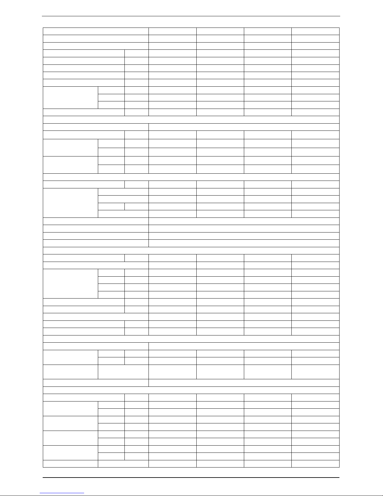
Model No. TAC-12CS/K TAC-12CHS/K TAC-18CS/K TAC-18CHS/K
Type Cooling Only Heating Pump Cooling Only Heating Pump
Control type Remote Remote Remote Remote
Rated cooling capacity Btu/h 12,000 12,000 18,000 18,000
Rated heating capacity Btu/h N/A 12,800 N/A 19,000
EER for cooling Btu/h.w 9.2 9.2 8.8 8.8
COP for heating W/W N/A 2.65 N/A 2.65
Moisture removal Liters/h 1.0 1.0 1.0 1.5
High dB(A) 38 38 42 42
Med. dB(A) 36 36 40 40
Indoor noise level at
cooling
Low dB(A) 32 32 36 36
Outdoor noise level dB(A) 52 52 58 58
Electrical Data
Power supply 220-240V~/50Hz
Voltage Range V
Cooling A 5.6 5.6 9.6 9.6
Rated current
Heating A N/A 5.9 N/A 9.0
Cooling W 1270 1270 2100 2100
Rated input
Heating W N/A 1335 N/A 1970
Refrigerating System
Refrigerant/Charge Gram R22/870g R22/870g R22/1700g R22/1700g
Type Rotary Rotary Rotary Rotary
Model ------------------ ----------------- ------------------ ------------------
LRA A ------ ------- ------ ------
Compressor
MFG ----------------- ----------------- ---------------- ----------------Evaporator Louver fin and Grooved tube type (φ7)
Condenser Corrugated fin and Grooved tube type (φ9.53)
Expansion device Capillary tube
Defrosting system Microcomputer controlled reverse system
Fan System
Indoor air circulation m3/h 530 530 800/850 800/850
Indoor fan type Cross flow Cross flow Cross flow Cross flow
Cooling rpm 1150/1060/900 1150/1060/900 1300/1200/1100 1300/1200/1100
Heating rpm N/A 1150/1060/900 N/A 1300/1200/1100
Dry rpm 900 900 840 840
Indoor fan speed
H/M/L
Sleep rpm 650 650 900/1000 900/1000
Indoor fan motor output W 12 12 25 25
Outdoor air circulation m3/h --- --- --- --Outdoor fan type Propeller fan Propeller fan Propeller fan Propeller fan
Outdoor fan speed rpm 860 860 820 820
Outdoor fan motor output W 55 55 90 90
Connections
Refrigerant coupling Flare type
Gas Inches 1/2 1/2 1/2 1/2
Connecting Pipe
Liquid Inches 1/4 1/4 1/4 1/4
Connecting Wiring
Size × Core
number
Drainage Pipe O.D 16mm
Others
Suitable area m2 16~28 16~28 30~40 30~40
Indoor mm 770×250×179 770×250×179 1036×313×204 1036×313×204Net dimensions
(W x H x D)
Outdoor mm 700×255×540 700×255×540 760×255×540 760×255×540
Indoor kg 8.0 8.0 14 14
Net weight
Outdoor kg 31 32 42 43
Indoor mm 863×325×270 863×325×270 1103×395×280 1103×395×280Packing dimensions
(W x H x D)
Outdoor mm 803×380×595 803×380×595 863×376×605 863×376×605
Indoor kg 10 10 19 19
Gross weight
Outdoor kg 34 35 44 45
Loading Capacity 40’/40’HC 111/238/276 111/238/276 90/188/218 90/188/218
Page 5
TCL Air Conditioner Service Manual
5
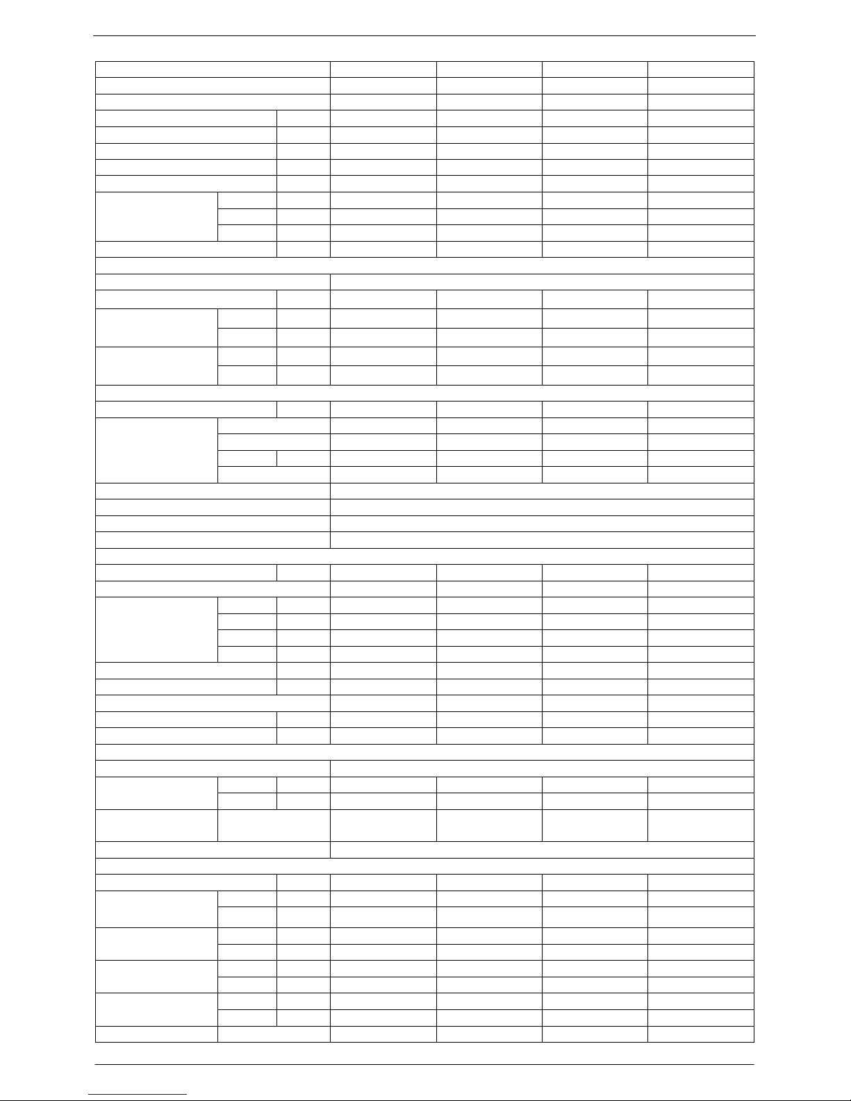
Model No. TAC-24CS/K TAC-24CHS/K
Type Cooling Only Heating Pump
Control type Remote Remote
Rated cooling capacity Btu/h 24,000 24,000
Rated heating capacity Btu/h N/A 26,000
EER for cooling Btu/h.w 9.0 9.0
COP for heating W/W N/A 2.55
Moisture removal Liters/h 2.2 2.2
High dB(A) 47 47
Med. dB(A) 44 44
Indoor noise level at
cooling
Low dB(A) 40 40
Outdoor noise level dB(A) 58 58
Electrical Data
Power supply 220-240V~/50Hz
Voltage Range V
Cooling A 13 13
Rated current
Heating A N/A 13.8
Cooling W 2600 2600
Rated input
Heating W N/A 2800
Refrigerating System
Refrigerant/Charge Gram R22/2500g R22/2500g
Type Rotary Rotary
Model ------------------ -----------------
LRA A ------ -------
Compressor
MFG ----------------- ----------------Evaporator Louver fin and Grooved tube type (φ7)
Condenser Corrugated fin and Grooved tube type (φ9.53)
Expansion device Capillary tube
Defrosting system Microcomputer controlled reverse system
Fan System
Indoor air circulation m3/h 1000 1000
Indoor fan type Cross flow Cross flow
Cooling rpm 1300/1200/1100 1300/1200/1100
Heating rpm N/A 1300/1200/1100
Dry rpm 1000 1000
Indoor fan speed
H/M/L
Sleep rpm 1000 1000
Indoor fan motor output W 35 35
Outdoor air circulation m3/h --- --Outdoor fan type Propeller fan Propeller fan
Outdoor fan speed rpm 850 850
Outdoor fan motor output W 110 110
Connections
Refrigerant coupling Flare type
Gas Inches 5/8 5/8
Connecting Pipe
Liquid Inches 3/8 3/8
Connecting Wiring
Size × Core
number
Drainage Pipe O.D 16mm
Others
Suitable area m
2
35~48 35~48
Indoor mm 1036×313×204 1036×313×204
Net dimensions
(W x H x D)
Outdoor mm 890×307×660 890×307×660
Indoor kg 16 16
Net weight
Outdoor kg 57 60
Indoor mm 1103×395×280 1103×395×280 Packing dimensions
(W x H x D)
Outdoor mm 990×405×705 990×405×705
Indoor kg 20 20
Gross weight
Outdoor kg 63 65
Loading Capacity 40’/40’HC 66/142/162 66/142/162
Note: The technical specifications is only reference.
Page 6
6
Note: Each mode and relevant function will be further specified in following pages.
SLEEP
FAN
TIMER
SWING
ON/OFF
MODE
MID
SWING
AUTO
DRY
FAN
HEAT
COOL
FEEL
SLEEP
TIMER ON
HIGH
LOW
TMIER OFF
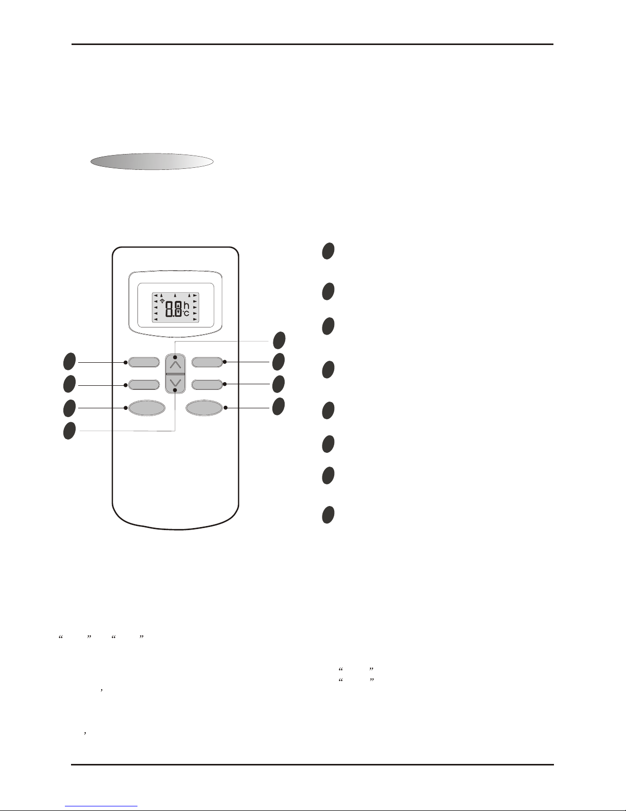
The remote controller transmits signals to the system.
Remote controller
1
2
4
3
5
6
7
8
8
4
MODE button
FAN SPEED control button
UP button (TOO COOL button)
DOWN button (TOO WARM button)
ON/OFF button
SLEEP button
VANE control button
TIMER button
Used to select the type of operation mode: Feel,
Cooling, Dry, Fan and Heating(Only for Heat Pump).
Used to select the indoor fan motor speed:
Auto, High, Mid and Low.
Used to increase the set room temperature
and time.
Used to decrease the set room temperature
and time.
Used to set or cancel sleep mode operation.
Used to start and stop operation
when pressed.
Used to adjust airflow direction.
Used to select TIMER operation.
Remote controller
6
2
5
3
7
1
11
TCL Air Conditioner Service Manual
Operation Details
Remote Control
The remote controller is not presetted as Cooling Only Air Conditioner or Heat Pump by manufacturer.
Each time after the remote controller replace batteries or is energized, the arrowhead will flashes on the front of
Heat or Cool on LCD of the remote controller.
User can preset the remote controller type depending on the air conditioner type you have purchased as
follows:
Press any button when the arrowhead flashes on the front of Cool , Cooling Only is set.
Press any button when the arrowhead flashes on the front of Heat , Heat Pump is set.
If you don t press any button within 10 seconds, the remote controller is preset as Heat Pump automatically.
Note :
If the air conditioner you purchased is a Cooling Only one, but you preset the remote controller as Heat Pump, it
doesn t bring any matter. But if the air conditioner you purchased is a Heat Pump one, and you preset the
remote controller as Cooling Only, then you CAN NOT preset the Heating operation with the remote controller.
Page 7

TCL Air Conditioner Service Manual
7
Elctronic Controller
1. Safety Control
(1) Time Delay Safety Control
3 minutes delay for compressor---The compressor is ceased for 3minutes to balance the pressure in the
refrigeration cycle in order to protect the compressor.
2 minutes delay for 4-way valve---The 4-way valve is ceased for 2 minutes to prevent the
refrigerant-gas abnormal noise when the HEATING operation is OFF or switch to the other operation
mode.
20 seconds delay for indoor fan--- When the assistant thermistor turns off, the indoor fan operates in
low speed for 20 seconds to release the heat of indoor unit.
(2) Indoor Pipe Temperature Sensor Frost Prevention Control
When the indoor pipe temperature sensor reads 0℃ or below for 5 minutes, the indoor pipe temperature
sensor frost prevention control starts. The compressor and outdoor fan stop and indoor fan operates at high
speed for 3 minutes. After that, if the indoor pipe temperature sensor reads less than 5℃ this control
prolonged until the indoor pipe temperature sensor reads 5℃ or more.
(3) High Temperature Protection Control
During HEATING operation, the outdoor fan motor and compressor are controlled by the indoor pipe
temperature to prevent the high temperature of compressor.
Outdoor fan OFF: 52℃
Outdoor fan ON:48℃
Compressor OFF:62℃
Compressor ON:48℃
2. “I Feel” Mode Operation
(1) When the “I Feel” mode is selected, the operation mode and initial set temperature are determined by the
initial room temperature at start-up of the operation except to turn off the air conditioner and operates it
again.
(2) If the mode is change to “I Feel” mode from other mode, the “I Feel” mode doesn’t operate until compressor
stop for more than 3 minutes.
In the “I Feel” mode , when the controller receives the up or down single of temperature, the set
temperature can adjust by 1
℃ upper or lower. The biggest you can adjust by 2℃ upper or lower.
3. “COOLING” Mode Operation
(1) When the COOLING mode is selected without setting temperature, the system will set the set temperature at
26
℃ automatically with the AUTO FAN speed.
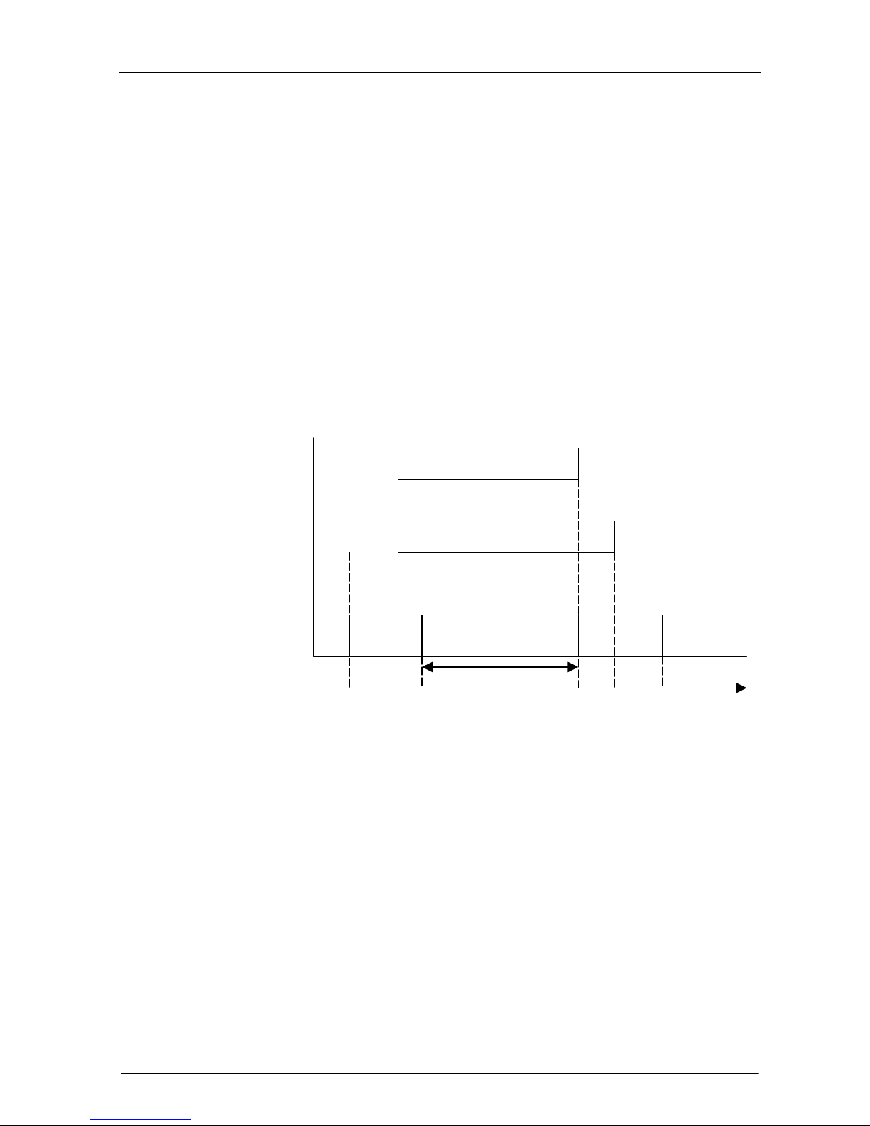
(2) When selecting the COOLING mode operation, the system will operate according to the setting by the
remote controller and the operation is as following:
Mode
Initial room temperature
COOLING
DRY
HEATING for Heat Pump Type
FAN for Cooling Only Type
26℃ or more
20℃ to 25 ℃
Less than 20℃
Initial set temperature
24℃
18℃
23℃
Page 8

TCL Air Conditioner Service Manual
8
Room Temp.
Set TEMP. +1
℃
Set TEMP. -1
℃
Time
More than 2 min More than 2 min More than 2 min More than 2 min More than 2 min
Indoor Fan Set Speed Set Speed Set Speed Set Speed Set Speed
Compressor ON OFF ON OFF ON
Outdoor Fan ON OFF ON OFF ON
4. “DRY” Mode Operation
(1) The system for DRY operation used the same refrigerant circle as the cooling circle.
(2) When the system operates in DRY mode ,at first it operates in cooling mode at 18
℃ for 3 minutes, and
then, the system operates in cooling mode with low speed that regards the temperature of the room
temperature sensor reads decrease 2℃ as the set temperature. During the course of this, the fan speed
setted operation is failing but the vane motor can be controlled.
5. “HEATING” Mode Operation (Only available for Heat Pump)
(1) When the HEATING mode is selected without setting temperature, the system will set the temperature at 23
℃ automatically with the AUTO FAN speed.
(2) When selecting the HEATING mode operation, the system will operate according to the setting by the
remote controller and the operation is as following:
Set Temp. +1℃
Set Temp. -1
℃
Room Temp.
Time
More than 2 min More than 2 min More than 2 min More than 2 min More than 2 min
Compressor ON OFF ON OFF ON
Outdoor fan ON OFF ON OFF ON
(3) In HEATING mode, the indoor fan motor is controlled by Cold Air Prevention Control.
(4) Cold Air Prevention Control
The function is intend to prevent cold air from being discharged when the heating operation starts or
when defrosting.
The indoor fan speed will be controlled as following:
The vane angle is at the angle C(100°).
34
℃
30
℃
27
℃
25
℃
23
℃
OFF UL Set Speed UL OFF UL
Indoor Pipe Temperature
Page 9
TCL Air Conditioner Service Manual
9
(5) Defrost
Defrosting of the outdoor heat exchange is controlled by the microprocessor with detection by the defrost
sensor.
Defrost starting conditions
When the conditions of a) or b) is satisfy, the defrosting operation starts.
a) Under the heating operation, the compressor cumulative operation time exceeds 50 minutes and the
temperature of the outdoor defrost sensor reads lower than -8
℃
b) Under the heating operation, the compressor cumulative operation time exceeds 50 minutes, if the
indoor pipe temperature sensor reads lower than 40
℃ continuously for 2minutes.
Note: If haven’t the outdoor pipe temperature sensor that use the condition b) to defrost, against
use the condition a).
Defrost terminating conditions
When the condition c) or d) is satisfy, the defrosting operation stops.
c) The outdoor defrost sensor reads 15
℃ or more.
d) The defrosting time exceeds 10 minutes.
Defrosting time chart
Outdoor Fan ON OFF ON
Revering Valve ON OFF ON
Compressor Relay ON OFF ON OFF ON
39S 5S Defrost Count MAX 12min 19S 15S t
(6) Assistant Thermistor Function
Assistant thermistor is add the thermitor of the electricity to rise the heating capacity automatically not
effected by the signal of the remote controller about assistant thermistor ON/OFF buttons.
1) When the condition all of A~G are satisfy, the assistant thermistor opens.
A. Under the heating operation, the compressor operates over than 3 minutes.
B. The indoor fan operates in normal.
C. The system operates not in defrosting.
D. The assistant thermistor turn off over than 30 seconds.
E. The set temperature is 3
℃ or more than the room temperature.
F. The room temperature sensor reads less than 22
℃.
G.
The indoor pipe temperature reads 43℃ or less.
2) When one of the conditions of A~E is satisfy, the assistant thermistor is off.
A. The compressor is turned off.
B. The room temperature sensor reads 24℃ or more.
C.
The indoor pipe temperature sensor reads 48℃ or more.
D.
The indoor fan is stopped.
6. “FAN” mode operation
Page 10
TCL Air Conditioner Service Manual
10
The indoor fan motor always turns on at the set speed and the vane motor turns on at the set fattle.
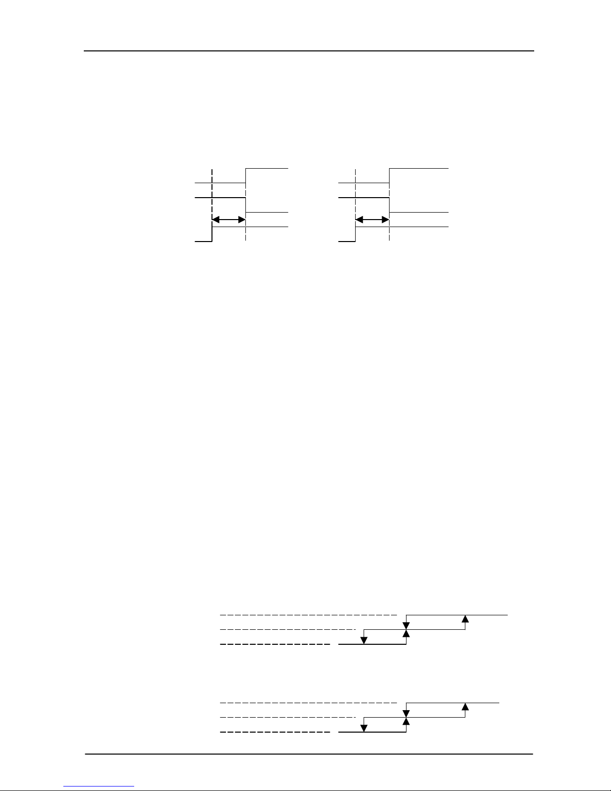
7. 4-way Valve contro
HEATING ON
COOLING/DRY OFF
The 4-way valve reverses for 5 seconds right before start-up of the compressor as following chart:
COOLING/DRY HEATING
Compressor
4-way Valve
5s 5s
Outdoor Fan
8. “SLEEP” mode
When the SLEEP button is pressed, the SLEEP mode is selected as following:
The indoor fan speed is set at the super low speed.
When selecting COOLING/DRY operation with SLEEP mode, the set temperature will be raised by 1
℃ 1
hour later and by 2℃ 2 hour later.
When selecting HEATING operation with SLEEP mode, the set temperature will be dropped by 1℃ 1
hour later and 2℃ 2hour later.
After the System operates in SLEEP mode for 8 hours, it will stop automatically.
9. Fan motor control
(1) Rotational frequency feedback control
The indoor fan motor is equipped with a rotational frequency sensor, and outputs signal to the
microprocessor to feedback the rotational frequency. Comparing the current rotational frequency with the
target rotational frequency, the microprocessor adjusts fan motor electric to make the current rotational
frequency close to the target rotational frequency. With this control, when the fan speed is switched, the
rotational frequency changes smoothly.
(2) When the rotational frequency feedback signal has not output for 5 seconds (or when the microprocessor
can’t detect the signal for 5 seconds), the fan motor is regarded locked-up. Then the electric current to the
fan motor is shut off. 10 seconds later, the electric current is applied to the fan motor again. During the fan
motor lock-up, the POWER indicator lamp flashes on and off to show the fan motor abnormality.
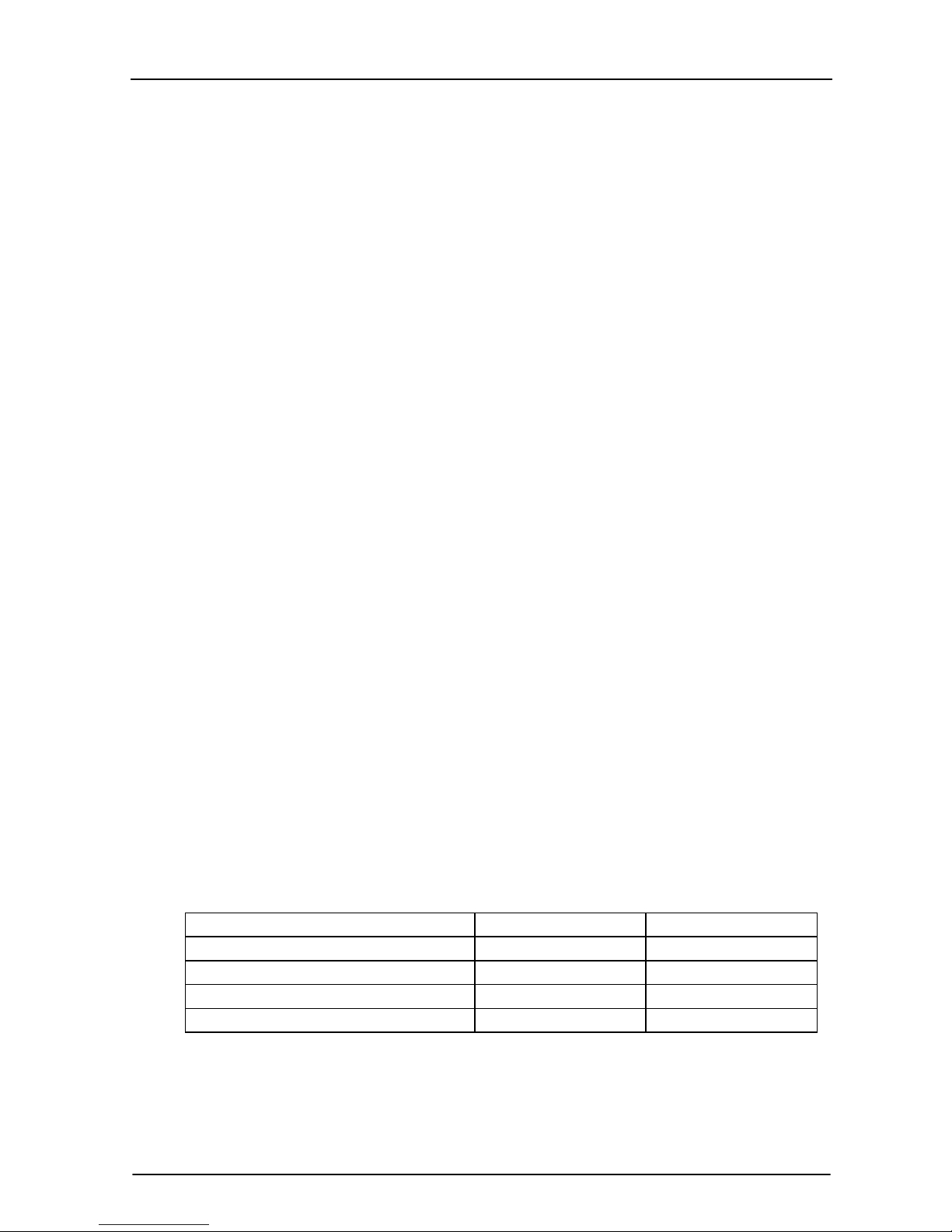
10. Auto Fan Speed Control
(1) When the auto fan speed is selected, the indoor fan motor speed is automatically controlled by the room
temperature and the set temperature.
(2) In COOLING mode, the indoor fan motor operates as following:
Fan Speed
Hi
Me
Lo
Room temperature minus set temperature: 1℃ 2℃ 4℃
(3) In HEATING mode, the indoor fan motor operates as following;
Fan Speed
Hi
Mi
Lo
Room temperature minus set temperature 1
℃ 2℃ 4℃
Page 11

TCL Air Conditioner Service Manual
11
11. Auto Vane Operation control
(1) Vane motor drive
The unit is equipped with a stepping motor for the vane. The rotating direction, speed, and angle of the
motor are controlled by pulse signal transmitted from indoor microprocessor.
(2) Positioning
The vane is once pressed to the vane stopper below to confirm the standard position and then set to the
desired angle. The positioning is decided as follows:
When the ON/OFF button is pressed.
When the vane control is change from AUTO to MANUAL.
When the SWING is finished.
When the test run starts.
When the power supply turns ON.
(3) The auto vane changes as follows by pressing the VANE CONTROL button.
(4) VANE AUTO mode
In vane auto mode, the microprocessor automatically determines the vane angle and operation to make the
optimum room-temperature distribution.
(5) SWING mode
When presses the SWING button, the vane swings.
12. TIMER Operation
(1) To activate the air conditioner at the desire time, follow the procedure specified below(the remote control
and air conditioner are switched off):
Press the Timer button.
Select the desired mode by pressing the Mode button.
Select the desired temperature by pressing the ▲ ▼ button (only possible when the ‘cool’ or ‘heat’
mode is selected).
Select the ventilator speed (low, medium or high) or automatic mode (only possible when the feel, Cool
or Heat mode is selected) by pressing the Fan button.
The ventilator always operates in the Auto mode when the Dry mode is selected.
Select Swing or no Swing by pressing the Swing button.
Press the Timer button (‘h’ flashes).
Use the ▲▼ button to select the time at which the air conditioner must activate (between 0 and 10
hours can be set at every half hour-between 10 and 24 hours can be set at every hour).
Press the Timer button (‘h’ stops flashing) and the preset time appears in the display.
Press the Timer button again to delete the selected data from the memory.
Note: If no buttons are pressed during the programming of the timer function, the remote control will switch
off automatically are after 10 seconds.
(2) To switch the air conditioner off at the desired time, follow the procedure specified below (the remote control
and air conditioner are switched off):
Press the Timer button.
Use the ▲▼ button to select the time at which the air conditioner must deactivate (between 0 to 10
hours can be set at every half hour-between 10 to 24 hours can be set at every hour).
Press the Timer button (‘h’ stops flashing), and the preset time will appear in the display.
Press the Timer button again to delete the selected data from the memory.
Note: If no buttons are pressed during the programming of the timer function, the remote control will switch
off automatically after 10 seconds.
Note: if ‘h’ is flashing and you press the ON/OFF/RUN button once, the preset temperature will appear in
Page 12
TCL Air Conditioner Service Manual
12
the display. You can now adjust the temperature with the ▲▼ button. Press the Timer button again to
display the time, which can now also be adjusted
☆
.
If the Timer button is pressed again, the data is stored and
the remaining time(that the air conditioner will be in operation) will appear in the display.
☆ Pressing the ON/OFF/RUN button instead of the Timer button deactivates the remote control.
Note: check that the TIMER INDICATOR on the indoor unit lights up after the timer has been set.
Press the Timer function to check the settings in the display.
13. EMERGENCY-TEST Operation
When the EMERGENCY Operation switch is pressed once, COOLING mode is selected and if in 3 seconds the
EMERGENCY Operation switch is pressed again, HEATING mode is selected. Then pressed once again, the unit
is switch off.
When the remote controller is missing, has failed or the batteries run down, press the EMERGENCY Operation
switch on the front of the indoor unit. The unit will start.
The first 30 minutes of operation will be the test run operation. The operation is for servicing. The indoor fan runs
at high speed and the system is in continuous operation. The thermostat is ON and the timer is reset to normal.
After 30 minutes of test run operation the system shifts to AUTO COOLING/HEATING mode, and the indoor fan
runs in automatic speed. The operation continues unit the EMERGENCY operation switch is pressed or a button
on the remote controller is pressed, the normal operation will start.
NOTE: Do not press the EMERGEMCY Operation switch during normal operation.
14.AUTO RESTART Function (Option)
When the indoor unit is controlled with the remote controller, the operation mode, set temperature, and the fan
speed are memorized by the indoor electric control PCB. The AUTO RESTART function sets to work the
moment power has restored after power failure. Then, the unit will restart automatically.
15. Failure Display and Handling
a) The failure of the resistance of heat sensitive:
When the resistance of heat sensitive reads the temperature is lower than -50
℃ or over than 110℃ that
judge the heat sensitive is bad.
b) The Outdoor Protection Control
When the system checks the signal from outdoor of the voltage is 0V, the system delay 1second to start for
check the signal again, if checks the signal of the voltage is 0V too, that the system not to star, or operates on
normal.
c) Failure Display
When the controller is failure, the buzzer will voice long for three times, and displays the failure from the
failure lamp.
d) Failure Code
If have the digital pipe that display the failure code for digital pipe, or display for the run lamp.
Type of failure The lamp flash Display of digital pipe
The failure of room temperature sensor Once/cycle E1
The failure of indoor pipe temperature sensor Twice/cycle E2
Outdoor protection function 5 times/cycle E5
The failure of indoor fan 6 times/cycle E6
e) Failure Handling
When the room temperature sensor or the indoor pipe temperature sensor is failure, the system will be
shut off, the compressor will be OFF, and the outdoor fan and the indoor fan will be OFF. The system
doesn’t receive the signal of remoter controller except the signal of shut off it. When the failure
eliminated, the controller can operate in normal mode. before this, presses the “ON/OFF” to start the
system, and it will operate in COOLING or HEATING for 30 minutes, and follows shut off. During
Page 13

TCL Air Conditioner Service Manual
13
this, it displays the failure and the protection is failing. You must be give the electric again to operate it.
In the failure, you can operate the FAN mode.
When the outdoor protects in the COOLING or DRY, the outdoor unit stops, the indoor fan operates in
set speed ; and in the HEATING, the outdoor unit stops, the assistant thermistor stops, the indoor fan
operates in cold air prevention control. The system doesn’t receive the signal of remoter controller
except the signal of shut off it. When the system check the voltage is 220V and the delay control is
finished, it operates at normal again.
When the indoor fan motor is failure, the compressor is stopped, the outdoor fan and indoor fan is
stopped and display the failure. The system doesn’t receive the signal of remoter controller except the
signal of shut off it.
f) Display Of The Control
In the display board the lamp from left is the POWER lamp (Red), the SLEEP lamp(Yellow), the TIMER
lamp(Yellow), the RUN lamp(Green).
(7) When gives the control electric, the buzzer voices a long for 0.3 second per cycle.
Page 14

TCL Air Conditioner Service Manual
14
Wiring Diagram
Mode No.: TAC-07CS/K, TAC-09CS/K, TAC-12CS/K
INDOOR UNIT
Pipe Temp.Sensor
Room Temp.Sensor
Display PCB
transformer
protector
Fan Motor
Vane Motor
M
M
θ
Indoor Unit
Power supply
Brown
Yellow/Green
evaporator
K1
TH2
TH1
CN6
CN8
CN3
CN4
CN5
3
COM
CN1
CN2
4
N.O.
P2-2
P2-1
PCB
Brown
Blue
Yellow/Green
Outdoor
Unit
Blue
1
N
OUTDOOR UNIT
Brown
Blue
Yellow/Green
Compressor
White
Red
Blue
Blue
Black
White
Blue
Yellow/Green
Blue
Yellow/Green
Fan Motor
Outdoor UnitIndoor Unit
Fan Capacitor
Compressor Capacitor
Orange
θ
Protector
R(M)
C
S
CM
1
N
M
Page 15

TCL Air Conditioner Service Manual
15
WIRING DIAGRAM
MODEL: TAC-07CHS/K,TAC-09CHS/K, TAC-12CHS/K
INDOOR UNIT:
Protecter
Fan Motor
Vane Motor
Indoor Unit
Evaporator
YLW/GRN
Brown
Red
Yellow
Blue
YLW/GRN
Display PCB
Pipe Temp. sensor
Room Temp. sensor
Transformer
Power Supply
Brown
Blue
PCB
CN1
CN2
TH1
TH2
P2-1
P5
P4
P2-2
NO
K1
COM
4
3
CN8
CN6
CN5 CN4
CN3
M
M
θ
N
3
2
1
Outdoor
Unit
1
2
3
N
YLW/GRN
Blue
Yellow
Red
Brown
OUTDOOR UNIT
θ
Compressor
4-way Vane
White
CM
R
(M)
C
S
Blue
Compressor
Capacitor
Red
Protecter
Black
Brown(White)
Red
Yellow
Blue
Yellow/Green
Blue
Yellow/Green
Outdoor UnitIndoor Unit
Fan Motor
Blue
Fan Capaciter
Blue
Yellow/Green
1
2
3
N
Blue
Blue
Orange
M
Page 16

TCL Air Conditioner Service Manual
16
Mode No.: TAC-18CS/K
INDOOR UNIT
PCB
Transformer
Brown
Blue
White
Blue
Yellow/Green
Yellow/Green
Yellow/Green
Yellow/Green
AC(N)
N.O
COM
Relay
1
N
N
L
Display PCB
Fan Motor
FM
SM
SM
Vane Motor
To The Outdoor
Room Temp. Sensor
Pipe Temp. Sensor
Blue
Brown
Blue
Brown
L
N
1234
1
2
3
4
5
1
2
3
4
5
OUTDOOR UNIT
Brown
Blue
Yellow/Green
Compressor
White
Red
Blue
Blue
Black
White
Blue
Yellow/Green
Blue
Yellow/Green
Fan Motor
Outdoor UnitIndoor Unit
Fan Capacitor
Compressor Capacitor
Orange
θ
Protector
R(M)
C
S
CM
1
N
M
Page 17

TCL Air Conditioner Service Manual
17
WIRING DIAGRAM
MODEL: TAC-18CHS/K
INDOOR UNIT:
Pipe Temp. Sensor
To O.P.T
PCB
AC(N)
Blue
To The Outdoor Unit
Brown
Blue
Yellow/Green
Yellow/Green
Brown
Blue
Yellow/Green
Yellow/Green
Display PCB
Red
Yellow
Brown
Relay
P5
P1
P3
P4
Red
White
Blue
Yellow
FM
SM
SM
Room Temp. Sensor
Vane Motor
Fan Motor
Transformer
CN3
P9-1
P9-2
CN5-1
CN5-2
CN6CN7
CN8
P2-1
CN2
CN1
OUTDOOR UNIT:
θ
Compressor
Valve Coil
White
CM
R
(M)
C
S
Blue
Compressor
Capacitor
Red
Protecter
Black
Brown(White)
Red
Yellow
Blue
Yellow/Green
Blue
Yellow/Green
Outdoor Unit
Indoor Unit
Fan Motor
Blue
Fan Capaciter
Blue
Yellow/Green
1
2
3
N
Blue
Blue
Orange
M
TH3
CN7
JUNCTION
JUNCTION
Inside/Outside
Page 18

TCL Air Conditioner Service Manual
18
Mode No.: TAC-24CS/K
INDOOR UNIT
Blue
N
Brown
Yellow/Green
L
White
White
1
PCB
Yellow/Green
Brown
Blue
N.O
COM
AC(N)
Relay
Transformer
FM
SM
Fan Motor
SM
Vane Motor
Display PCB
Room Temp. Sensor
Pipe Temp. Sensor
12
3
4
4
5
3
2
1
5
4
3
2
1
To Outdoor Unit
OUTDOOR UNIT
Conpressor
W hite
W hite
Yellow/Green
Blue
Brown
Yello w/Green
Brown
Blue
Blue
Brown
Brown
Brown
Yellow/Green
Red
W hite
Yellow
Red
C1
Blue
Blue
W hite
Fan Capacitor
Cap a cito r
Red
Blue
C2
To Power Supply
To Indoor Unit
Yellow/Green
Relay
Fan Motor
Conpressor
Motor
C
S
R
FM
CM
1
N
L
L
N
Page 19

TCL Air Conditioner Service Manuel
19
WIRING DIAGRM
MODEL: TAC-24CHS/K
INDOOR UNIT:
SM
FM
SM
OUTDOOR UNIT:
White
White
Red
Yellow Blue
Brown
YLW/GRN
Blue
Red
Brown
YLW/GRN
Brown
Blue
Blue
Brown
To Power Supply
To Indoor Unit
Valve Coil
Yellow
Red
C1
Fan Capacitor
Blue
Blue
Red
Compressor
Capacity
White
C2
YLW/GRN
Compressor
Blue
Motor
Fan Motor
Relay
O.P.T
FM
FM
C
S
R
1
2
3
N
L
L
N
YLW/GRN
Blue
Junction
Page 20

TAC Air Conditioner Service Manual
20
EXPLOSION VIEW
Model: TAC-07CS/K, TAC-07CHS/K, TAC-09CS/K, TAC-09CHS/K, TAC-12CS/K,
TAC-12CHS/K
INDOOR UNIT:
1
2
3
5
14
6
7
8
9
10
15
16
17
18
19
20
21
22
23
24
25
26
27
11
12
13
4
28
29
Page 21

TCL Air Conditioner Service Manual
21
INDOOR UNIT
TAC-18CS/K, TAC-18CHS/K, TAC-24CS/K, TAC-24CHS/K
1
2
3
4
5
6
7
8
9
10
11
12
13
29
28
27
26
25
24
23
22
21
20
19
18
17
16
14
15
30
Page 22

TCL Air Conditioner Service Manual
22
EXPLOSION VIEW
Model: TAC-07CS/K, TAC-09CS/K
OUTDOOR UNIT:
1
2
3
5
4
6
7
9
10
11
12
13
14
15
16
17
8
18
19
20
21
22
23
24
25
Page 23

TCL Air Conditioner Service Manual
23
EXPLOSION VIEW
Model : TAC-12CS/K, TAC-18CS/K
OUTDOOR UNIT
1
2
3
5
4
6
7
9
10
11
12
13
14
15
16
17
8
18
19
20
21
22
23
24
25
26
Page 24

TCL Air Conditioner Service Manual
24
EXPLOSION VIEW
Model : TAC-24CS/K
OUTDOOR UNIT
1
2
3
5
4
6
7
9
10
11
13
14
15
16
17
8
18
19
2
0
21
22
23
24
25
26
12
Page 25

TCL Air Conditioner Service Manual
19
EXPLOSION VIEW
Mode: TAC-07CHS/K, TAC-09CHS/K
OUTDOOR UNIT:
1
2
3
4
5
6
7
8
9
10
11
12
13
14
15
16
17
18
19
20
21
22
23
24
25
26
27
28
29
Page 26

TCL Air Conditioner Service Manual
20
EXPLOSION VIEW
MODEL: TAC-12CHS/K, TAC-18CHS/K
INDOOR UNIT:
1
2
3
4
5
6
7
8
9
10
11
12
13
14
15
16
17
18
19
20
21
22
23
24
25
26
27
28
29
30
Page 27

TCL Air Conditioner Service Manual
27
EXPLOSION VIEW
MODEL: TAC-24CHS/K
OUTDOOR UNIT:
1
2
3
4
5
6
7
8
9
10
11
12
13
14
15
16 19
17
18
20
21
22
23
24
25
26
27
28
29
Page 28

TCL Air Conditioner Service Manual
28
Parts List
Indoor Unit- TAC-07CS/K, TAC-09CS/K
No. Part No. Part Name Q’ty Remark
1 1080030003 Installation Plate 1
2 1210250103 Base 1
3 1070020017 Cross Fan 1
4 1070100010 Bearing Mount 1
5 1210230101 Evaporator 1
6 1070250102 Water Drainage Assembly 1
7 1070320105 Vertical Vane Assembly 2
8 1070250104 Face Frame 1
9 1070320112 Screw Cover 2
10 1090320102 Display PCB 1
11 1070320115 Display PCB Box 1
12 1070250110 Display PCB Cover 1
13 1070250106 Air Filter 2
14 1070251801 Front Panel 1
15 1170120038 Power Supply Cord 1
16 1070250103 Vane 1
17 1070110008 Drainage Hose 1
18 1070040004 Cable Clamp 1
19 1170200039 Terminal 1
20 1070250109 Terminal Fixing Board 1
21 1090250602 Main PCB 1
22 1070320113 Electrical Box 1
23 1170020011 Vane Motor 1
24 1073030201 Sensor Holder 1
25 1170030047 Indoor Motor 1
26 1070320111 Indoor Motor Cover 1
27 1170240001 Transformer 1
28 1170230001 Pipe Temp. Sensor & Room
Temp. Sensor Assembly
1
29 1070320101 In And Out Pipe Fixer 1
30 1090010071 Remote Controller 1
31 1073030303 Remote Controller Supporter 1
31 1190060007 Indoor Carton 1
32 1190060008 Left Foaming 1
33 1190060009 Right Foaming 1
Not shown in Explosion
view
Page 29

TCL Air Conditioner Service Manual
29
Parts List
Indoor Unit- TAC-07CHS/K, TAC-09CHS/K
No. Part No. Part Name Q’ty Remark
1 1080030003 Installation Plate 1
2 1210250103 Base 1
3 1070020017 Cross Fan 1
4 1070100010 Bearing Mount 1
5 1210230101 Evaporator 1
6 1070250102 Water Drainage Assembly 1
7 1070320105 Vertical Vane Assembly 2
8 1070250104 Face Frame 1
9 1070320112 Screw Cover 2
10 1090320102 Display PCB 1
11 1070320115 Display PCB Box 1
12 1070250110 Display PCB Cover 1
13 1070250106 Air Filter 2
14 1070251801 Front Panel 1
15 1170120044 Power Supply Cord 1
16 1070250103 Vane 1
17 1070110008 Drainage Hose 1
18 1070040004 Cable Clamp 1
19 1170200040 Terminal 1
20 1070250109 Terminal Fixing Board 1
21 1090250202 Main PCB 1
22 1070320113 Electrical Box 1
23 1170020011 Vane Motor 1
24 1073030201 Sensor Holder 1
25 1170030047 Indoor Motor 1
26 1070320111 Indoor Motor Cover 1
27 1170240001 Transformer 1
28 1170230001 Pipe Temp. Sensor & Room
Temp. Sensor Assembly
1
29 1070320101 In And Out Pipe Fixer 1
30 1090010071 Remote Controller 1
31 1073030303 Remote Controller Supporter 1
31 1190060007 Indoor Carton 1
32 1190060008 Left Foaming 1
33 1190060009 Right Foaming 1
Not shown in Explosion
view
Page 30

TCL Air Conditioner Service Manual
30
Parts List
Indoor Unit- TAC-12CS/K
No. Part No. Part Name Q’ty Remark
1 1080030008 Installation Plate 1
2 1210320107 Base 1
3 1070020016 Cross Fan 1
4 1070100010 Bearing Mount 1
5 1210320601 Evaporator 1
6 1210320108 Water Drainage Assembly 1
7 1070320105 Vertical Vane Assembly 2
8 1070320107 Face Frame 1
9 1070320112 Screw Cover 2
10 1090320102 Display PCB 1
11 1070320115 Display PCB Box 1
12 1070320110 Display PCB Cover 1
13 1070320109 Air Filter 2
14 1070321501 Front Panel 1
15 1170120047 Power Supply Cord 1
16 1070320104 Vane 1
17 1070110008 Drainage Hose 1
18 1070040004 Cable Clamp 1
19 1170200039 Terminal 1
20 1070250109 Terminal Fixing Board 1
21 1090320702 Main PCB 1
22 1070320113 Electrical Box 1
23 1170020011 Vane Motor 1
24 1073030201 Sensor Holder 1
25 1170030047 Indoor Motor 1
26 1070320111 Indoor Motor Cover 1
27 1170240001 Transformer 1
28 1170230001 Pipe Temp. Sensor & Room
Temp. Sensor Assembly
1
29 1070320101 In And Out Pipe Fixer 1
30 1090010071 Remote Controller 1
31 1073030303 Remote Controller Supporter 1
31 1190060010 Indoor Carton 1
32 1190060008 Left Foaming 1
33 1190060009 Right Foaming 1
Not shown in Explosion
view
Page 31

TCL Air Conditioner Service Manual
31
Indoor Unit - TAC-12CHS/K
No. Part No. Part Name Q’ty Remark
1 1080030008 Installation Plate 1
2 1210320107 Base 1
3 1070020016 Cross Fan 1
4 1070100010 Bearing Mount 1
5 1210320601 Evaporator 1
6 1070320103 Water Drainage Assembly 1
7 1070320105 Vertical Vane Assembly 2
8 1070320107 Face Frame 1
9 1070320112 Screw Cover 2
10 1090320102 Display PCB 1
11 1070320115 Display PCB Box 1
12 1070320110 Display PCB Cover 1
13 1070320109 Air Filter 2
14 1070321501 Front Panel 1
15 1170120047 Power Supply Cord 1
16 1070320104 Vane 1
17 1070110008 Drainage Hose 1
18 1070040006 Electrical Box Cover 1
19 1070040004 Cable Clamp 1
20 1170200040 Terminal 1
21 1070250109 Terminal Fixing Board 1
22 1170020011 Vane Motor 1
23 1090320103 Main PCB 1
24 1110040001 Sensor Holder 1
25 1070320113 Electrical Box 1
26 1170030047
27 1070320111 1
28 1170240001 Transformer 1
29 1170230001 Pipe Temp. Sensor & Room
Temp. Sensor Assembly
1
30 1070320101 In And Out Pipe Fixer 1
31 1090010071 Remote Controller 1
31 1073030303 Remote Controller Supporter 1
32 1190060010 Indoor Carton 1
33 1190060005 Left Foaming 1
34 1190060006 Right Foaming 1
Not shown in Explosion
view
Indoor Motor
Indoor Motor Cover
1
Page 32

TCL Air Conditioner Service Manual
32
Indoor Unit- TAC-18CS/K
No. Part No. Part Name Q’ty Remark
1 1080030001 Installation Plate 1
2 1213090101 Base 1
3 1070020014 Cross Fan 1
4 1070100010 Bearing Mount 1
5 1213090105 Evaporator 1
6 1213090102 Water Drainage Assembly 1
7 1073090106 Vertical Vane Assembly 2
8 1073090110 Face Frame 1
9 1073090111 Screw Cover 3
10 1093090102 Display PCB 1
11 1073090126 Display PCB Box 1
12 1073090112 Air Filter 2
13 1070500205 Front Panel 1
14 1073090131 Display PCB Cover 1
15 1073090132 Electrical Box Cover 1
16 1170120049 Power Supply Cord 1
17 1073090108 Vane A 1
18 1073090125 Vane B 1
19 1070110008 Drainage Hose 1
20 1070040003 Cable Clamp 1
21 1170020011 Vane Motor 1
22 1170200038-39 Terminal 2
23 1083090108 Terminal Fixing Board 1
24 1073030201 Sensor Holder 1
25 1093090201 Main PCB 1
26 1073090120 Indoor Motor Cover 1
27 1170030045 Indoor Motor 1
28 1093090121 Electrical Box 1
29 1173090107 Transformer 1
30 1170230001 Pipe Temp. Sensor & Room
Temp. Sensor Assembly
1
31 1090010071 Remote Controller 1
31 1073030303 Remote Controller Supporter 1
32 1190060003 Indoor Carton 1
33 1190060019 Left Foaming 1
34 1190060020 Right Foaming 1
35 1190060002 Middle Pasteboard Supporter 1
36 1190060021 Middle Foaming Supporter 1
Not shown in Explosion
view
Page 33

TCL Air Conditioner Service Manual
33
Indoor Unit- TAC-18CHS/K
No. Part No. Part Name Q’ty Remark
1 1080030001 Installation Plate 1
2 1073090101 Base 1
3 1070020014 Cross Fan 1
4 1070100010 Bearing Mount 1
5 1213090106 Evaporator 1
6 1213090102 Water Drainage Assembly 1
7 1073090106 Vertical Vane Assembly 2
8 1073090110 Face Frame 1
9 1073090111 Screw Cover 3
10 1093090102 Display PCB 1
11 1073090126 Display PCB Box 1
12 1073090112 Air Filter 2
13 1070500205 Front Panel 1
14 1073090131 Display PCB Cover 1
15 1073090122 Electrical Box Cover 1
16 1170120049 Power Supply Cord 1
17 1073090108 Vane A 1
18 1073090125 Vane B 1
19 1070110008 Drainage Hose 1
20 1070040003 Cable Clamp 2
21 1170020011 Vane Motor 1
22 1170200040 Terminal 2
23 1083090108 Terminal Fixing Board 1
24 1110040001 Sensor Holder 1
25 1090520109 Main PCB 1
26 1073090120 Indoor Motor Cover 1
27 1170030045 Indoor Motor 1
28 1093090121 Electrical Box 1
29 1173090107 Transformer 1
30 1170230001 Pipe Temp. Sensor & Room
Temp. Sensor Assembly
1
31 1090010071 Remote Controller 1
31 1073030303 Remote Controller Supporter 1
32 1190060003 Indoor Carton 1
33 1190060019 Left Foaming 1
34 1190060020 Right Foaming 1
35 1190060002 Middle Pasteboard Supporter 1
36 1190060021 Middle Foaming Supporter 1
Not shown in Explosion
view
Page 34

TCL Air Conditioner Service Manual
34
Indoor Unit- TAC-24CS/K
No. Part No. Part Name Q’ty Remark
1 1080030001 Installation Plate 1
2 1073090101 Base 1
3 1070020014 Cross Fan 1
4 1070100010 Bearing Mount 1
5 1210700205 Evaporator 1
6 1213090102 Water Drainage Assembly 1
7 1073090106
1073090107
Vertical Vane Assembly A
Vertical Vane Assembly B
1
1
8 1073090110 Face Frame 1
9 1073090111 Screw Cover 3
10 1093090102 Display PCB 1
11 1073090126 Display PCB Box 1
12 1073090112 Air Filter 2
13 1070500205 Front Panel 1
14 1073090131 Display PCB Cover 1
15 1073090132 Electrical Box Cover 1
16 1170120030 Power Supply Cord 1
17 1073090108 Vane A 1
18 1073090125 Vane B 1
19 1070110008 Drainage Hose 1
20 1070040002 Cable Clamp 1
21 1170020011 Vane Motor 1
22 1170200042 Terminal 1
23 1083090108 Terminal Fixing Board 1
24 1073030201 Sensor Holder 1
25 1090700102 Main PCB 1
26 1073090120 Indoor Motor Cover 1
27 1170030048 Indoor Motor 1
28 1093090121 Electrical Box 1
29 1173090107 Transformer 1
30 1170230001 Pipe Temp. Sensor & Room
Temp. Sensor Assembly
1
31 1090010071 Remote Controller 1
31 1073030303 Remote Controller Supporter 1
32 1190060003 Indoor Carton 1
33 1190060019 Left Foaming 1
34 1190060020 Right Foaming 1
35 1190060002 Middle Pasteboard Supporter 1
36 1190060021 Middle Foaming Supporter 1
Not shown in Explosion
view
Page 35

TCL Air Conditioner Service Manual
35
Indoor Unit- TAC-24CHS/K
No. Part No. Part Name Q’ty Remark
1 1080030001 Installation Plate 1
2 1073090101 Base 1
3 1070020014 Cross Fan 1
4 1070100010 Bearing Mount 1
5 1210700205 Evaporator 1
6 1213090102 Water Drainage Assembly 1
7 1073090106 Vertical Vane Assembly 2
8 1073090110 Face Frame 1
9 1073090111 Screw Cover 3
10 1093090102 Display PCB 1
11 1073090126 Display PCB Box 1
12 1073090112 Air Filter 2
13 1070500205 Front Panel 1
14 1073090131 Display PCB Cover 1
15 1073090122 Electrical Box Cover 1
16 1170120030 Power Supply Cord 1
17 1073090108 Vane A 1
18 1073090125 Vane B 1
19 1070110008 Drainage Hose 1
20 1070040003 Cable Clamp 2
21 1170020011 Vane Motor 1
22 1170200041 Terminal 2
23 1083090108 Terminal Fixing Board 1
24
25 1090700204 Main PCB 1
26 1073090120 Indoor Motor Cover 1
27 1170030048 Indoor Motor 1
28 1093090121 Electrical Box 1
29 1173090107 Transformer 1
30 1170230001 Pipe Temp. Sensor & Room
Temp. Sensor Assembly
1
31 1090010071 Remote Controller 1
31 1073030303 Remote Controller Supporter 1
32 1190060003 Indoor Carton 1
33 1190060019 Left Foaming 1
34 1190060020 Right Foaming 1
35 1190060002 Middle Pasteboard Supporter 1
36 1190060021 Middle Foaming Supporter 1
Not shown in Explosion
view
Sensor Holder 1073090127 1
Page 36

TCL Air Conditioner Service Manual
36
Outdoor Unit- TAC-07CS/K, TAC-09CS/K
No. Part No. Part Name Q’ty Remark
1 1083510901 Grille 1
Optional
2 1080050016 Top Cover 1
3 1210250304 Condenser 1
4 1080050015 Outdoor Motor Supporter 1
5 1170040062 Outdoor Motor 1
6 1070030006 Propeller Fan 1
7 1080050012 Left Plate 1
8 1080050018 Front Plate 1
9 1080050019 Fan Guard 1
10 1210250312 Capillary Assembly 1
11 1100010008 Compressor and its Accessories 1
12 1120250611 Discharge Pipe 1
13 1123521408 Suction Pipe 1
14 1210250301 Base 1
15 1120120008 Two-way Valve 1
16 1080050014 Valve Supporter 1
17 1120130011 Three-way Valve 1
18 1080050013 Right Plate 1
19 1073521301 Electrical Box Cover 1
20 1080020001 Electrical Parts Box 1
21 1080010002 Capacitor Strip 1
22 1170100003 Compressor Capacitor 1
23 1170100031 Fan Motor Capacitor 1
24 1170200019 Terminal 1
25 1070040002 Cable Clamp(φ7) 1
26 1190070014 Base Carton 1
27 1190070008 Cabinet Carton 1
28 1190070016 Base Foaming 1
29 1190070015 Cover Forming 1
Not shown in the Explosion
view.
Page 37

TCL Air Conditioner Service Manual
37
Part List
Outdoor Unit- TAC-07CHS/K, TAC-09CHS/K
No. Part No. Part Name Q’ty Remark
1 1083510901 Grille 1
2 1080050016 Top Cover 1
3 1210250304 Condenser 1
4 1080050015 Outdoor Motor Supporter 1
5 1170040062 Outdoor Motor 1
6 1070030006 Propeller Fan 1
7 1080050012 Left Plate 1
8 1080050018 Front Plate 1
9 1080050019 Fan Guard 1
10 1100170018 Compressor and its Accessories 1
11 1123530404 Suction Pipe 1
12 1123530407 Three-way Valve Connecting Pipe 1
13 1123530405 Discharge Pipe 1
14 1120110002 4-way Valve Assembly 1
15 1123530406 Condenser Connecting Pipe 1
16 1213530414 Base 1
17 1080050013 Right Plate 1
18 1120120008 Two-way Valve 1
19 1080050014 Valve Supporter 1
20 1120130011 Three-way Valve 1
21 1073521301 Electrical Box Cover 1
22 1070040001 Cable Clamp 1
23 1070040002 Cable Clamp 1
24 1170200020 Terminal 1
25 1170100031 Fan Motor Capacitor 1
26 1170100014 Compressor Capacitor 1
1080010002 Capacitor Strip
28 1080020001 Electrical Parts Box 1
29 1210250150 Capillary Assembly 1
30 1190070014 Base Carton 1
31 1190250201 Cabinet Carton 1
32 1190070016 Base Foaming 1
33 1190070015 Cover Forming 1
Not shown in the Explosion
view.
Page 38

TCL Air Conditioner Service Manual
38
Outdoor Unit- TAC-12CS/K
No. Part No. Part Name Q’ty Remark
1 1080050025 Grille 1
Optional
2 1080320105 Top Cover 1
3 1210320106 Condenser 1
4 1080050004 Outdoor Motor Supporter 1
5 1170040058 Outdoor Motor 1
6 1070030016 Propeller Fan 1
7 1080050001 Left Grille Supporter 1
8 1080050007 Left Grille 1
9 1080320113 Front Plate 1
9 1080320112 Fan Guard 1
10 1210320705 Capillary Assembly 1
11 1100170004 Compressor and its Accessories 1
12 1120320707 Discharge Pipe 1
13 1120320708 Suction Pipe 1
14 1210320103 Base 1
15 1120120016 Two-way Valve 1
16 1080050003 Valve Supporter 1
17 1120130021 Three-way Valve 1
18 1080050002 Right Plate 1
19 1073551103 Electrical Box Cover 1
20 1080010006 Capacitor Strip 1
21 1070040003 Cable Clamp(φ8) 1
22 1170200019 Terminal 1
23 1170100003 Compressor Capacitor 1
24 1170100010 Fan Motor Capacitor 1
25 1080020001 Electrical Parts Box 1
26 1190070014 Base Carton 1
27 1190070008 Cabinet Carton 1
28 1190070016 Base Foaming 1
29 1190070015 Cover Forming 1
Not shown in the Explosion
view.
Page 39

TCL Air Conditioner Service Manual
39
Outdoor Unit- TAC-12CHS/K
No. Part No. Part Name Q’ty Remark
1 1080050025 Grille 1
Optional
2 1080320105 Top Cover 1
3 1210350201 Condenser 1
4 1080050004 Outdoor Motor Supporter 1
5 1170040058 Outdoor Motor 1
6 1070030016 Propeller Fan 1
7 1080050001 Left Grille Supporter 1
8 1080050007 Left Grille 1
9 1080320113 Front Plate 1
10 1080320112 Fan Guard 1
11 1100170004 Compressor And It Accessories 1
12 1120320102 Suction Pipe 1
13 1 120320103 Three-way Valve connecting Pipe 1
14 1120320115 Discharge Pipe 1
15 1120110002 4-way Vane Assembly 1
16 1120320104 Condenser connecting Pipe 1
17 1210320103 Base 1
18 1080050002 Right Plate 1
19 1120120016 Two-way Valve 1
20 1080050003 Valve Supporter 1
21 1120130021 Three-way Valve 1
22 11073551103 Electrical Box Cover 1
23 1070040001 Cable Clamp(φ6) 1
24 1070040002 Cable Clamp(φ7) 1
25 1170200020 Terminal 1
26 1170100032 Fan Motor Capacitor
27 1170100003 Compressor Capacitor 1
28 1080010006 Capacitor Strip
29 1080020001 Electrical Parts Box
30 1210320115 Capillary Assembly
31 1190070017 Base Carton 1
32 1190500302 Cabinet Carton 1
33 1190070019 Base Foaming 1
34 1190070018 Cover Forming 1
Not shown in the Explosion
view.
Page 40

TCL Air Conditioner Service Manual
40
Outdoor Unit- TAC-18CS/K
No. Part No. Part Name Q’ty Remark
1 1080050026 Grille 1
Optional
2 1080050011 Top Cover 1
3 1210500109 Condenser 1
4 1080050004 Outdoor Motor Supporter 1
5 1170040059 Outdoor Motor 1
6 1070030012 Propeller Fan 1
7 1080050001 Left Grille Supporter 1
8 1080050007 Left Grille 1
9 1080050009 Front Plate 1
10 1080320112 Fan Guard 1
11 1213590202 Capillary Assembly 1
12 1100010011 Compressor and its Accessories 1
13 1120500211 Discharge Pipe 1
14 1120500210 Suction Pipe 1
15 1210500106 Base 1
16 1120120016 Two-way Valve 1
17 1080050003 Valve Supporter 1
18 1120130021 Three-way Valve 1
19 1080050002 Right Plate 1
20 1073551103 Electrical Box Cover 1
21 1080010006 Capacitor Strip 1
22 1070040003 Cable Clamp(φ8) 1
23 1170200019 Terminal 1
24 1170100007 Compressor Capacitor 1
25 1170100027 Fan Motor Capacitor 1
26 1080020001 Electrical Parts Box 1
27 1190070020 Base Carton 1
28 1190070002 Cabinet Carton 1
29 1190070022 Base Foaming 1
30 1190070021 Cover Forming 1
Not shown in the Explosion
view.
Page 41

TCL Air Conditioner Service Manual
41
Part List
Outdoor Unit- TAC-18CHS/K
No. Part No. Part Name Q’ty Remark
1 1084530501 Grille 1
Optional
2 1080050011 Top Cover 1
3 1210500351 Condenser 1
4 1080050004 Outdoor Motor Supporter 1
5 1170040059 Outdoor Motor 1
6 1070030012 Propeller Fan 1
7 1080050001 Left Grille Supporter 1
8 1080050007 Left Grille 1
9 1080050009 Front Plate 1
10 1080320112 Fan Guard 1
11 1100010011 Compressor And It Accessories 1
12 1120500107 Suction Pipe 1
13 1120500109 Three-way Valve connecting Pipe 1
14 1120500108 Discharge Pipe 1
15 1120110003 4-way Vane Assembly 1
16 1120500110 Condenser connecting Pipe 1
17 1210500106 Base 1
18 1080050002 Right Plate 1
19 1120120016 Two-way Valve 1
20 1080050003 Valve Supporter 1
21 1120130021 Three-way Valve 1
22 1073551103 Electrical Box Cover 1
23 1070040001 Cable Clamp(φ6) 1
24 1170040003 Cable Clamp(φ8) 1
25 1170200020 Terminal 1
26 1170100027 Fan Motor Capacitor 1
27 1170100007 Compressor Capacitor 1
28 1080010006 Capacitor Strip 1
29 1080020001 Electrical Parts Box 1
30 1210700203 Capillary Assembly 1
31 1174561802 Outdoor Sensor 1
31 1190070020 Base Carton 1
32 1190070002 Cabinet Carton 1
33 1190070004 Upper Forming 1
34 1190070021 Base Forming 1
Not show in the explosion
Page 42

TCL Air Conditioner Service Manual
42
Outdoor Unit- TAC-24CS/K
No. Part No. Part Name Q’ty Remark
1 1084530501 Grille 1
Optional
2 1084530504 Top Cover 1
3 1210700102 Condenser 1
4 1084530510 Outdoor Motor Supporter 1
5 1170040063 Outdoor Motor 1
6 1070030017 Propeller Fan 1
7 1084530516 Left Plate 1
8 1084530514 Front Plate 1
9 1084530515 Fan Guard 1
10 1120700103 Suction Pipe 1
11 1214561809 Base 1
12 1100060013 Compressor and its Accessories 1
13 1084530503 Right Plate 1
14 1084530502 Valve Supporter 1
15 1120120011 Two-way Valve 1
16 1120130013 Three-way Valve 1
17 1074530503 Electrical Box Cover 1
18 1080010004 Capacitor Strip 1
19 1074060118 Cable Clamp 1
20 1170200037 Terminal 1
21 1170100007 Compressor Capacitor 1
22 1170100030 Fan Motor Capacitor 1
23 1174561801 AC Contactor 1
24 1084561802 Electrical Parts Box 1
25 1120700102 Discharge Pipe 1
26 1210700101 Capillary Assembly 1
27 1190070003 Base Carton 1
28 1190070013 Cabinet Carton 1
29 1190070004 Cover Carton 1
Not shown in the Explosion
view.
Page 43

TCL Air Conditioner Service Manual
43
Part List
Outdoor Unit- TAC-24CHS/K
No. Part No. Part Name Q’ty Remark
1 1084530501 Grille 1
Optional
2 1084530504 Top Cover 1
3 1210700211 Condenser 1
4 1084530510 Outdoor Motor Supporter 1
5 1170040063 Outdoor Motor 1
6 1070030017 Propeller Fan 1
7 1084530516 Left Plate 1
8 1084530514 Front Plate 1
9 1084530515 Fan Guard 1
10 1100060013 Compressor And It Accessories 1
11 1210700203 Capillary Assembly 1
12 1120700215 Suction Pipe 1
13 1 120700205 Three-way Valve connecting Pipe 1
14 1120700203 Discharge Pipe 1
15 1120110001 4-way Vane Assembly 1
16 1120700206 Condenser connecting Pipe 1
17 1214561809 Base 1
18 1120120011 Two-way Valve 1
19 1084530502 Valve Supporter 1
20 1120130013 Three-way Valve 1
21 1084530503 Right Plate 1
22 1074530503 Electrical Box Cover 1
23 1074060118 Cable Clamp 1
24 1170200036 Terminal 1
25 1080010006 Capacitor Strip 1
26 1170100007 Compressor Capacitor
27 1170100030 Fan Motor Capacitor 1
28 1080010004 Electrical Parts Box
29 1174561801 AC Contactor
30 1174561802 Outdoor Sensor
31 1190070003 Base Carton
32 1190070013 Cabinet Carton 1
33 1190070004 Upper Carton 1
Not show in the explosion
1
1
1
1
1
 Loading...