

Page 1
TAC-09CSC/K TAC-09CHSC/K
TCL
14. ANNEX 5 INSTALLATION INSTRUCTION Part 1
SERVICE MANUAL
TAC-07CSC/K TAC-07CHSC/K
TAC-12CSC/K TAC-12CHSC/K
TAC-18CSC/K TAC-18CHSC/K
TAC-24CSC/K TAC-24CHSC/K
No.TE031229
TAC-18CS/K TAC-18CHS/K
WALL MOUNTED SPLIT-TYPE AIR CONDITIONERS
Models
TAC-07CS/K TAC-07CHS/K
TAC-09CS/K
TAC-12CS/K
TAC-24CS/K
TAC-24CHS/K
TAC-09CHS/K
TAC-12CHS/K
CONTENTS
1. IMPORTANT NOTICE ···································2
2. TECHNICAL SPECIFICATION ·····················3
3. DIMENSIONS ················································8
4. REFRIGERATING CYCLE SYSTEM ············· 9
5. PERFORMANCE CURVES ····························12
6. OPERATION DETAILS ·············16
7. WIRING DIAGRAM ······························23
8. EXPLOSION VIEW ···················29
9. PARTS LIST ·································33
10. ANNEX 1 THERMISTOR CHARACTERISTIC
11. ANNEX 2 GENERAL
12. ANNEX 3 TROUBLE SHOOTING
13. ANNEX 4 R407C REFRIGERANT
Page 2

IMPORTANT NOTICE
This service manual is intended for use by individuals possessing adequate
backgrounds of electrical, electronic and mechanical experience. Any
attempt to repair the appliance may result in personal injury and property
damage. The manufacturer or seller cannot be responsible for the
interpretation of this information, nor can it assume any liability in
connection with its use.
The information, specifications and parameter are subject to change due to
technical modification or improvement without any prior notice. The
accurate specifications are presented on the nameplate label.
How to order spare parts
To have your order filled promptly and correctly, please furnish the
following information:
1. Model No. with Indoor or Outdoor
2. No. in the Explosion View
3. Part Name
4. The quantity you ordered
TCL Air Conditioner Service ManualTCL Air Conditioner Service ManualTCL Air Conditioner Service Manual
TCL Air Conditioner Service Manual
2
Page 3
TCL Air Conditioner Service Manual
3
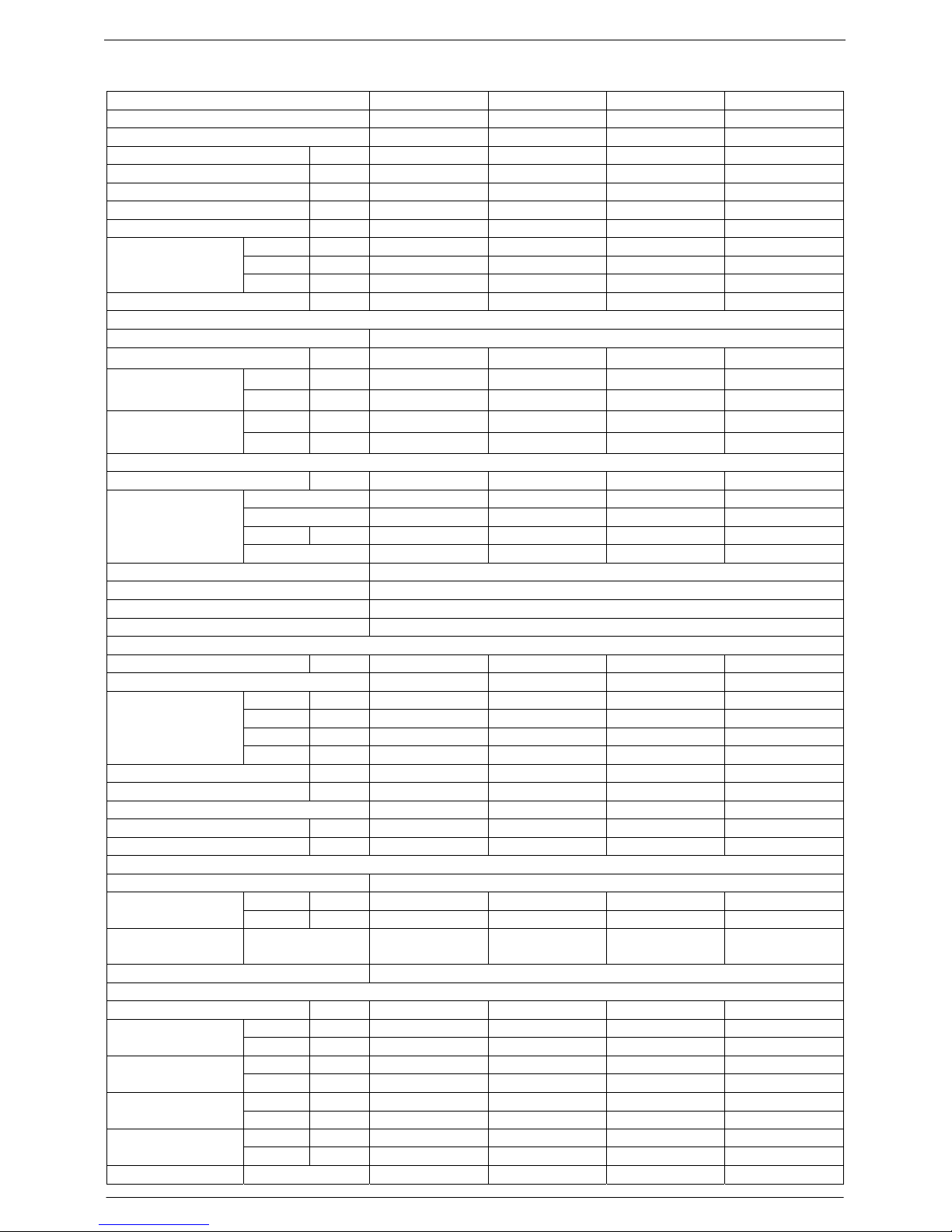
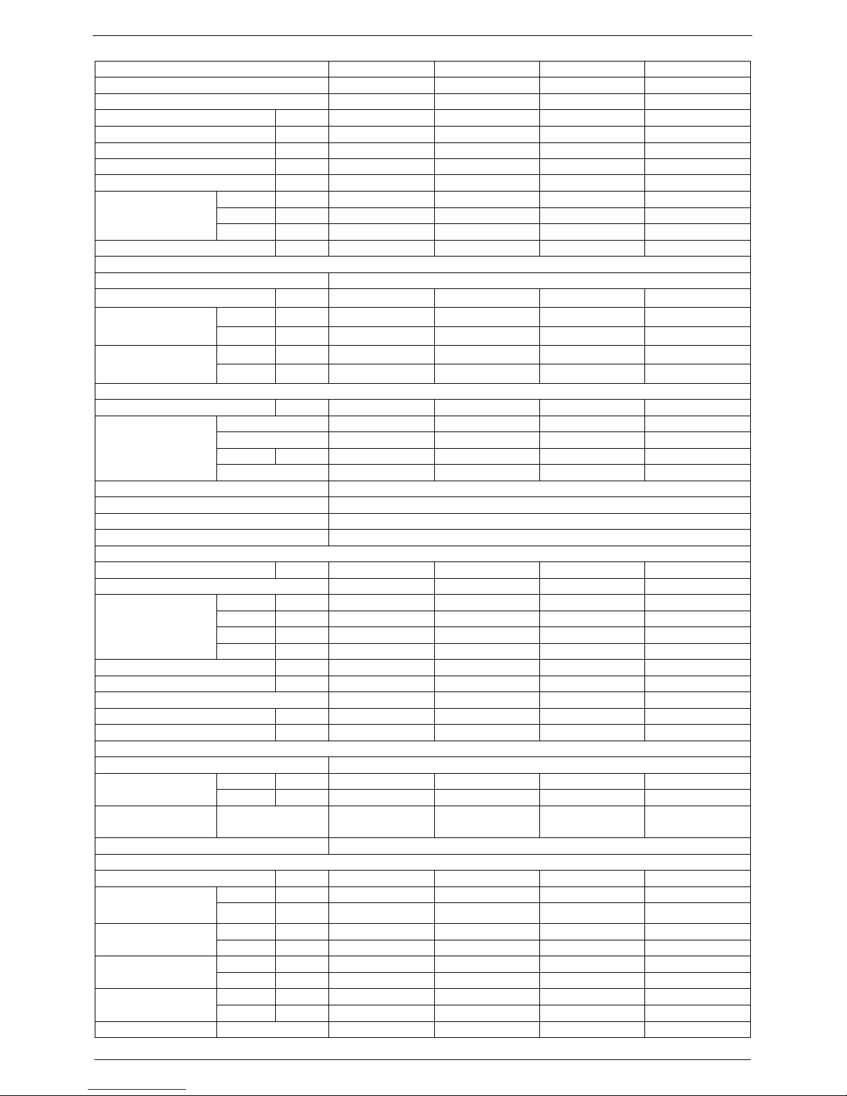
Technical Specifications
Model No. TAC-07CS/K TAC-07CHS/K TAC-09CS/K TAC-09CHS/K
Type Cooling Only Heating Pump Cooling Only Heating Pump
Control type Remote Remote Remote Remote
Rated cooling capacity Btu/h 7,000 7,000 9,000 9,000
Rated heating capacity Btu/h N/A 7,500 N/A 9,500
EER for cooling Btu/h.w 9.6 9.6 9.6 9.6
COP for heating W/W N/A 2.8 N/A 2.8
Moisture removal Liters/h 0.8 0.8 0.8 0.8
High dB(A) 36 36 36 36
Med. dB(A) 32 32 32 32
Indoor noise level at
cooling
Low dB(A) 29 29 29 29
Outdoor noise level dB(A) 50 50 50 50
Electrical Data
Power supply 220-240V~/50Hz
Voltage Range V 198~264 198~264 198~264 198~264
Cooling A 4.2 4.2 4.2 4.2
Rated current
Heating A N/A 4.1 N/A 4.1
Cooling W 895 895 900 900
Rated input
Heating W N/A 880 N/A 880
Refrigerating System
Refrigerant/Charge Gram R22/700g R22/700g R22/700g R22/700g
Type Rotary Rotary Rotary Rotary
Model ------------------ ----------------- ------------------ -----------------LRA A ------ ------- ------ ------
Compressor
MFG ----------------- ----------------- ---------------- -----------------
Evaporator Louver fin and Grooved tube type (φ7)
Condenser Corrugated fin and Grooved tube type (φ9.53)
Expansion device Capillary tube
Defrosting system Microcomputer controlled reverse system
Fan System
Indoor air circulation m3/h 430 430 430 430
Indoor fan type Cross flow Cross flow Cross flow Cross flow
Cooling rpm 1000/950/900 1000/950/900 1000/950/900 1000/950/900
Heating rpm N/A 970/900/800 N/A 970/900/800
Dry rpm 900 900 900 900
Indoor fan speed
H/M/L
Sleep rpm 650 650 650 650
Indoor fan motor output W 12 12 12 12
Outdoor air circulation m3/h --- --- --- --Outdoor fan type Propeller fan Propeller fan Propeller fan Propeller fan
Outdoor fan speed rpm 895 895 895 895
Outdoor fan motor output W 31 31 31 31
Connections
Refrigerant coupling Flare type
Gas Inches 5/8 5/8 5/8 5/8
Connecting Pipe
Liquid Inches 7/16 7/16 7/16 7/16
Connecting Wiring
Size × Core
number
Drainage Pipe O.D 16mm
Others
Suitable area m2 12~19 12~19 12~19 12~19
Indoor mm 710×250×179 710×250×179 710×250×179 710×250×179Net dimensions
(W x H x D)
Outdoor mm 600×500×232 600×500×232 600×500×232 600×500×232
Indoor kg 7.5 7.5 7.5 7.5
Net weight
Outdoor kg 25 25 25 25
Indoor mm 805×325×270 805×325×270 805×325×270 805×325×270Packing dimensions
(W x H x D)
Outdoor mm 745×352×542 745×352×542 745×352×542 745×352×542
Indoor kg 10 10 10 10
Gross weight
Outdoor kg 28 29 28 29
Loading Capacity 40’/40’HC 132/280/318 132/280/318 132/280/318 132/280/318
Page 4

TCL Air Conditioner Service Manual
4
Model No. TAC-07CSC/K TAC-07CHSC/K TAC-09CSC/K TAC-09CHSC/K
Type Cooling Only Heating Pump Cooling Only Heating Pump
Control type Remote Remote Remote Remote
Rated cooling capacity Btu/h 7,000 7,000 9,000 9,000
Rated heating capacity Btu/h N/A 7,500 N/A 9,500
EER for cooling Btu/h.w 11.0 11.0 11.0 11.0
COP for heating W/W N/A 3.2 N/A 3.2
Moisture removal Liters/h 0.8 0.8 0.8 0.8
High dB(A) 38 38 38 38
Med. dB(A) 36 36 36 36
Indoor noise level at
cooling
Low dB(A) 32 32 32 32
Outdoor noise level dB(A) 50 50 50 50
Electrical Data
Power supply 220-240V~/50Hz
Voltage Range V 198~264 198~264 198~264 198~264
Cooling A 4.1 4.1 4.1 4.1
Rated current
Heating A N/A 4.1 N/A 4.1
Cooling W 880 880 880 880
Rated input
Heating W N/A 880 N/A 880
Refrigerating System
Refrigerant/Charge Gram R407C/700g R407C/700g R407C/700g R407C/700g
Type Rotary Rotary Rotary Rotary
Model ------------------ ----------------- ------------------ ------------------
LRA A ------ ------- ------ ------
Compressor
MFG ----------------- ----------------- ---------------- ----------------Evaporator Louver fin and Grooved tube type (φ7)
Condenser Corrugated fin and Grooved tube type (φ9.53)
Expansion device Capillary tube
Defrosting system Microcomputer controlled reverse system
Fan System
Indoor air circulation m3/h 480 480 480 480
Indoor fan type Cross flow Cross flow Cross flow Cross flow
Cooling rpm 1230/1150/1000 1230/1150/1000 1230/1150/1000
1230/1150/1000
Heating rpm N/A 1230/1150/1000 N/A
1230/1150/1000
Dry rpm 1000 1000 1000 1000
Indoor fan speed
H/M/L
Sleep rpm 1000 1000 1000 1000
Indoor fan motor output W 12 12 12 12
Outdoor air circulation m3/h --- --- --- --Outdoor fan type Propeller fan Propeller fan Propeller fan Propeller fan
Outdoor fan speed rpm 860 860 860 860
Outdoor fan motor output W 31 31 31 31
Connections
Refrigerant coupling Flare type
Gas Inches 7/16 7/16 3/4 3/4
Connecting Pipe
Liquid Inches 3/4 3/4 7/16 7/16
Connecting Wiring
Size × Core
number
Drainage Pipe O.D 16mm
Others
Suitable area m2 12~19 12~19 12~19 12~19
Indoor mm 770×250×179 770×250×179 770×250×179 770×250×179Net dimensions
(W x H x D)
Outdoor mm 700×255×540 700×255×540 700×255×540 700×255×540
Indoor kg 8.0 8.0 8 8
Net weight
Outdoor kg 31 32 31 32
Indoor mm 863×325×270 863×325×270 863×325×270 863×325×270Packing dimensions
(W x H x D)
Outdoor mm 803×380×598 803×380×598 803×380×598 803×380×598
Indoor kg 10 10 10 10
Gross weight
Outdoor kg 35 36 35 36
Loading Capacity 40’/40’HC 111/238/276 111/238/276 111/238/276 111/238/276
Page 5
TCL Air Conditioner Service Manual
5
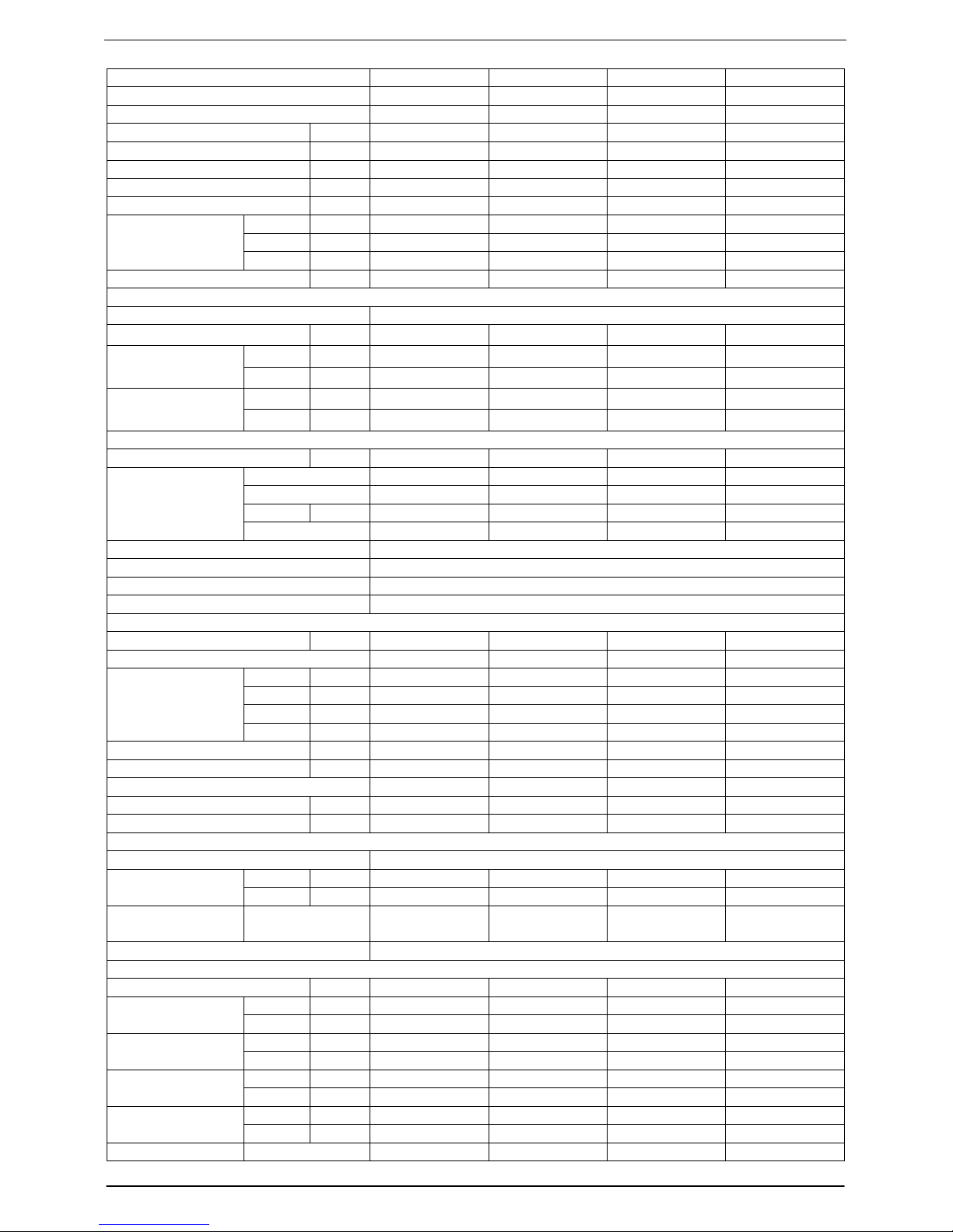
Model No. TAC-12CS/K TAC-12CHS/K TAC-18CS/K TAC-18CHS/K
Type Cooling Only Heating Pump Cooling Only Heating Pump
Control type Remote Remote Remote Remote
Rated cooling capacity Btu/h 12,000 12,000 18,000 18,000
Rated heating capacity Btu/h N/A 12,800 N/A 19,000
EER for cooling Btu/h.w 9.2 9.2 8.8 8.8
COP for heating W/W N/A 2.65 N/A 2.65
Moisture removal Liters/h 1.0 1.0 1.0 1.5
High dB(A) 38 38 42 42
Med. dB(A) 36 36 40 40
Indoor noise level at
cooling
Low dB(A) 32 32 36 36
Outdoor noise level dB(A) 52 52 58 58
Electrical Data
Power supply 220-240V~/50Hz
Voltage Range V 198~264 198~264 198~264 198~264
Cooling A 5.6 5.6 9.6 9.6
Rated current
Heating A N/A 5.9 N/A 9.0
Cooling W 1270 1270 2100 2100
Rated input
Heating W N/A 1335 N/A 1970
Refrigerating System
Refrigerant/Charge Gram R22/870g R22/870g R22/1700g R22/1700g
Type Rotary Rotary Rotary Rotary
Model ------------------ ----------------- ------------------ ------------------
LRA A ------ ------- ------ ------
Compressor
MFG ----------------- ----------------- ---------------- ----------------Evaporator Louver fin and Grooved tube type (φ7)
Condenser Corrugated fin and Grooved tube type (φ9.53)
Expansion device Capillary tube
Defrosting system Microcomputer controlled reverse system
Fan System
Indoor air circulation m3/h 530 530 800/850 800/850
Indoor fan type Cross flow Cross flow Cross flow Cross flow
Cooling rpm 1150/1060/900 1150/1060/900 1300/1200/1100 1300/1200/1100
Heating rpm N/A 1150/1060/900 N/A 1300/1200/1100
Dry rpm 900 900 840 840
Indoor fan speed
H/M/L
Sleep rpm 650 650 900/1000 900/1000
Indoor fan motor output W 12 12 25 25
Outdoor air circulation m3/h --- --- --- --Outdoor fan type Propeller fan Propeller fan Propeller fan Propeller fan
Outdoor fan speed rpm 860 860 820 820
Outdoor fan motor output W 55 55 90 90
Connections
Refrigerant coupling Flare type
Gas Inches 7/16 7/16 3/4 3/4
Connecting Pipe
Liquid Inches 3/4 3/4 7/16 7/16
Connecting Wiring
Size × Core
number
Drainage Pipe O.D 16mm
Others
Suitable area m2 16~28 16~28 30~40 30~40
Indoor mm 770×250×179 770×250×179 1036×313×204 1036×313×204Net dimensions
(W x H x D)
Outdoor mm 700×255×540 700×255×540 760×255×540 760×255×540
Indoor kg 8.0 8.0 14 14
Net weight
Outdoor kg 31 32 42 43
Indoor mm 863×325×270 863×325×270 1103×395×280 1103×395×280Packing dimensions
(W x H x D)
Outdoor mm 803×380×595 803×380×595 863×376×605 863×376×605
Indoor kg 10 10 19 19
Gross weight
Outdoor kg 34 35 44 45
Loading Capacity 40’/40’HC 111/238/276 111/238/276 90/188/218 90/188/218
Page 6
TCL Air Conditioner Service Manual
6
Model No. TAC-12CSC/K TAC-12CHSC/K TAC-18CSC/K TAC-18CHSC/K
Type Cooling Only Heating Pump Cooling Only Heating Pump
Control type Remote Remote Remote Remote
Rated cooling capacity Btu/h 12,000 12,000 18,000 18,000
Rated heating capacity Btu/h N/A 12,800 N/A 1,9000
EER for cooling Btu/h.w 10.9 10.9 9.5 9.5
COP for heating W/W N/A 3.2 N/A 2.8
Moisture removal Liters/h 1.0 1.0 1.5 1.5
High dB(A) 38 38 43 43
Med. dB(A) 36 36 40 40
Indoor noise level at
cooling
Low dB(A) 32 32 36 36
Outdoor noise level dB(A) 52 52 58 58
Electrical Data
Power supply 220-240V~/50Hz
Voltage Range V 198~264 198~264 198~264 198~264
Cooling A 5.5 5.5 8.7 8.7
Rated current
Heating A N/A 5.5 N/A 8.7
Cooling W 1170 1170 1900 1900
Rated input
Heating W N/A 1170 N/A 1900
Refrigerating System
Refrigerant/Charge Gram R407C/1450g R407C/1450g R407C/1800g R407C/1800g
Type Rotary Rotary Rotary Rotary
Model ------------------ ----------------- ------------------ ------------------
LRA A ------ ------- ------ ------
Compressor
MFG ----------------- ----------------- ---------------- ----------------Evaporator Louver fin and Grooved tube type (φ7)
Condenser Corrugated fin and Grooved tube type (φ9.53)
Expansion device Capillary tube
Defrosting system Microcomputer controlled reverse system
Fan System
Indoor air circulation m3/h 550 550 730 730
Indoor fan type Cross flow Cross flow Cross flow Cross flow
Cooling rpm 1230/1150/1000 1230/1150/1000 1060/970/880
1060/970/880
Heating rpm N/A 1230/1150/1000 N/A
1060/970/880
Dry rpm 1000 1000 880 880
Indoor fan speed
H/M/L
Sleep rpm 1000 1000 880 880
Indoor fan motor output W 12 12 25 25
Outdoor air circulation m3/h --- --- --- --Outdoor fan type Propeller fan Propeller fan Propeller fan Propeller fan
Outdoor fan speed rpm 860 860 850 850
Outdoor fan motor output W 55 55 85 85
Connections
Refrigerant coupling Flare type
Gas Inches 3/4 3/4 3/4 3/4
Connecting Pipe
Liquid Inches 7/16 7/16 7/16 7/16
Connecting Wiring
Size × Core
number
Drainage Pipe O.D 16mm
Others
Suitable area m2 16~28 16~28 30~40 30~40
Indoor mm 770×250×179 770×250×179 1036×313×204 1036×313×204Net dimensions
(W x H x D)
Outdoor mm 760×255×540 760×255×540 890×307×660 890×307×660
Indoor kg 8.0 8.0 13 13
Net weight
Outdoor kg 37 37 48 48
Indoor mm 863×325×270 863×325×270 1103×395×280 1103×395×280Packing dimensions
(W x H x D)
Outdoor mm 863×376×605 863×376×605 990×405×705 990×405×705
Indoor kg 10 10 10 10
Gross weight
Outdoor kg 35 36 35 36
Loading Capacity 40’/40’HC 112/236/248 112/236/248 66/142/162 66/142/162
Page 7
TCL Air Conditioner Service Manual
7
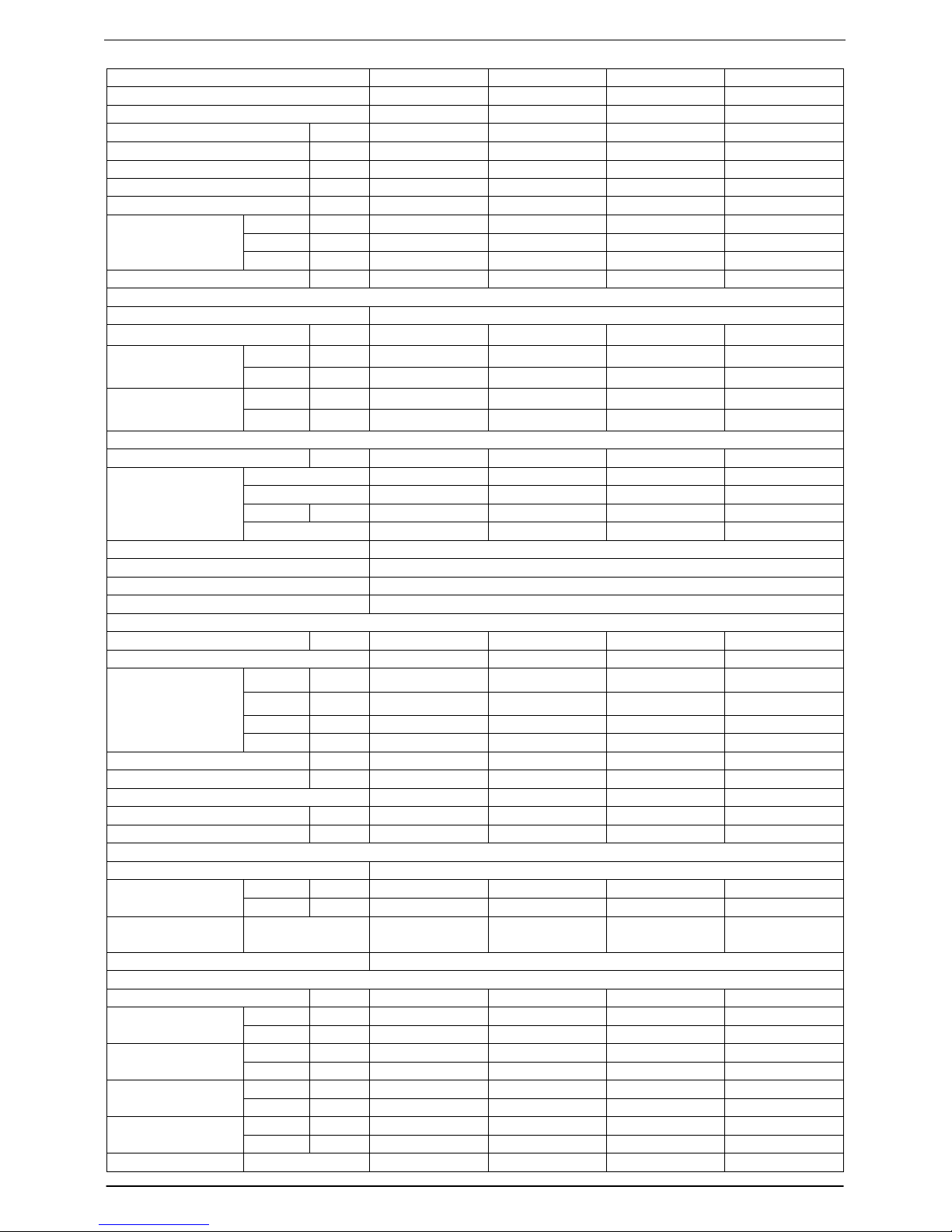
Model No. TAC-24CS/K TAC-24CHS/K TAC-24CSC/K TAC-24CHSC/K
Type Cooling Only Heating Pump Cooling Only Heating Pump
Control type Remote Remote Remote Remote
Rated cooling capacity Btu/h 24,000 24,000 24,000 24,000
Rated heating capacity Btu/h N/A 26,000 N/A 26,000
EER for cooling Btu/h.w 9.0 9.0 9.2 9.2
COP for heating W/W N/A 2.55 N/A 2.8
Moisture removal Liters/h 2.2 2.2 2.2 2.2
High dB(A) 47 47 47 47
Med. dB(A) 44 44 44 44
Indoor noise level at
cooling
Low dB(A) 40 40 40 40
Outdoor noise level dB(A) 58 58 58 58
Electrical Data
Power supply 220-240V~/50Hz
Voltage Range V 198~264 198~264 198~264 198~264
Cooling A 13 13 11.8 11.8
Rated current
Heating A N/A 13.8 N/A 11.8
Cooling W 2600 2600 2600 2600
Rated input
Heating W N/A 2800 N/A 2600
Refrigerating System
Refrigerant/Charge Gram R22/2500g R22/2500g R407C/2540g R407C/2540g
Type Rotary Rotary Rotary Rotary
Model ------------------ ----------------- ------------------ ------------------
LRA A ------ ------- ------ ------
Compressor
MFG ----------------- ----------------- ---------------- ----------------Evaporator Louver fin and Grooved tube type (φ7)
Condenser Corrugated fin and Grooved tube type (φ9.53)
Expansion device Capillary tube
Defrosting system Microcomputer controlled reverse system
Fan System
Indoor air circulation m3/h 1000 1000 1000 1000
Indoor fan type Cross flow Cross flow Cross flow Cross flow
Cooling rpm 1300/1200/1100 1300/1200/1100 1300/1250/1150 1300/1250/1150
Heating rpm N/A 1300/1200/1100 N/A 1300/1250/1150
Dry rpm 1000 1000 1150 1150
Indoor fan speed
H/M/L
Sleep rpm 1000 1000 1150 1500
Indoor fan motor output W 35 35 35 35
Outdoor air circulation m3/h --- --- --- --Outdoor fan type Propeller fan Propeller fan Propeller fan Propeller fan
Outdoor fan speed rpm 850 850 850 850
Outdoor fan motor output W 110 110 85 85
Connections
Refrigerant coupling Flare type
Gas Inches 7/8 7/8 7/8 7/8
Connecting Pipe
Liquid Inches 5/8 5/8 5/8 5/8
Connecting Wiring
Size × Core
number
Drainage Pipe O.D 16mm
Others
Suitable area m2 35~48 35~48 35~48 35~48
Indoor mm 1036×313×204 1036×313×204 1036×313×204 1036×313×204
Net dimensions
(W x H x D)
Outdoor mm 890×307×660 890×307×660
890×307×660
890×307×660
Indoor kg 16 16 16 16
Net weight
Outdoor kg 57 60 57 60
Indoor mm 1103×395×280 1103×395×280 1103×395×280 1103×395×280Packing dimensions
(W x H x D)
Outdoor mm 990×405×705 990×405×705 990×405×705 990×405×705
Indoor kg 20 20 20 20
Gross weight
Outdoor kg 63 65 63 65
Loading Capacity 40’/40’HC 66/142/162 66/142/162 66/142/162 66/142/162
Note: The technical specifications is only reference.
Page 8
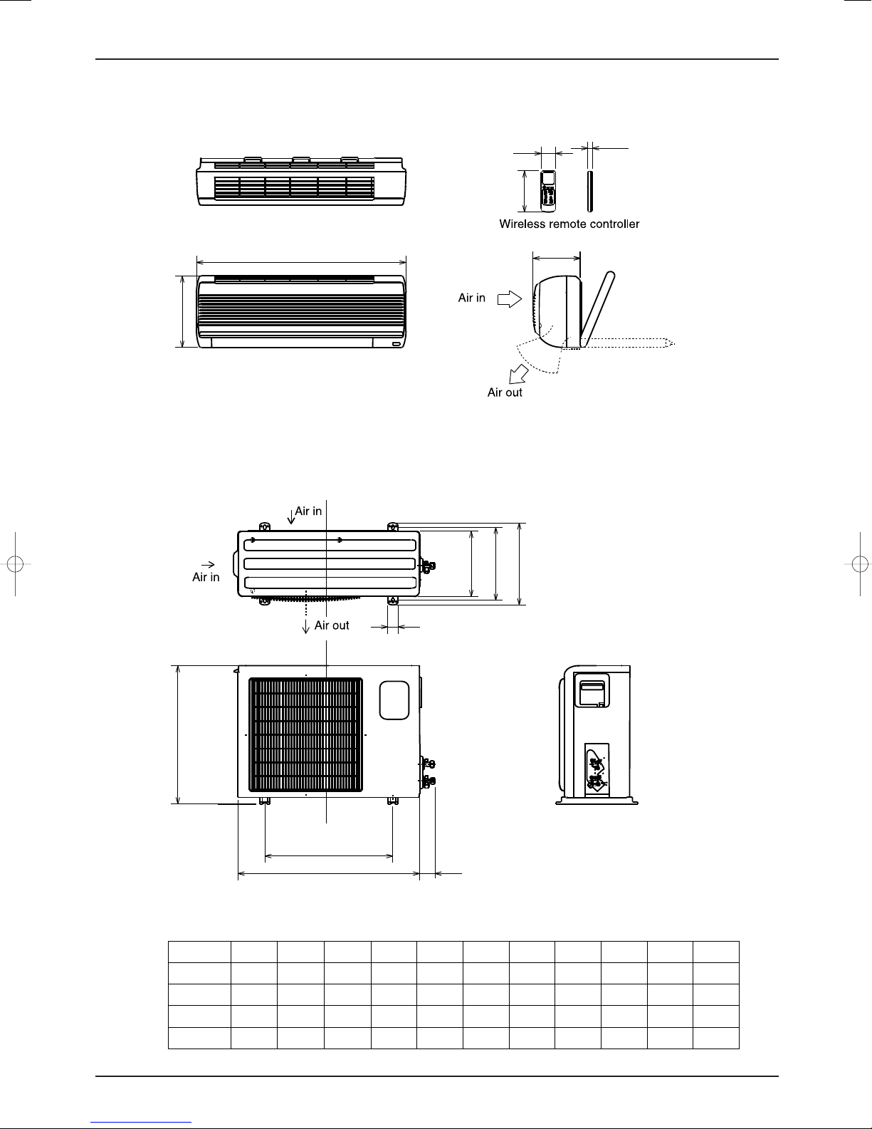
Product Dimensions
Outdoor Unit
Indoor Unit
A
B
16mm
124mm
54 mm
C
H
G
F
I
K
J
D
E
Unit: mm
TCL Air Conditioner Service Manual
8
Capacity A B C D E F G H I J K
7K&9K 710 250 179 600 500 231 271 296 52 365
12K 770865 250 179 700 540 255 290 320 40 439 55
18K 1036 313 204 760 540 255 340 370 62 635 63
24K 1036 313 204 860 730 307 340 370 62 635 63
55
Page 9
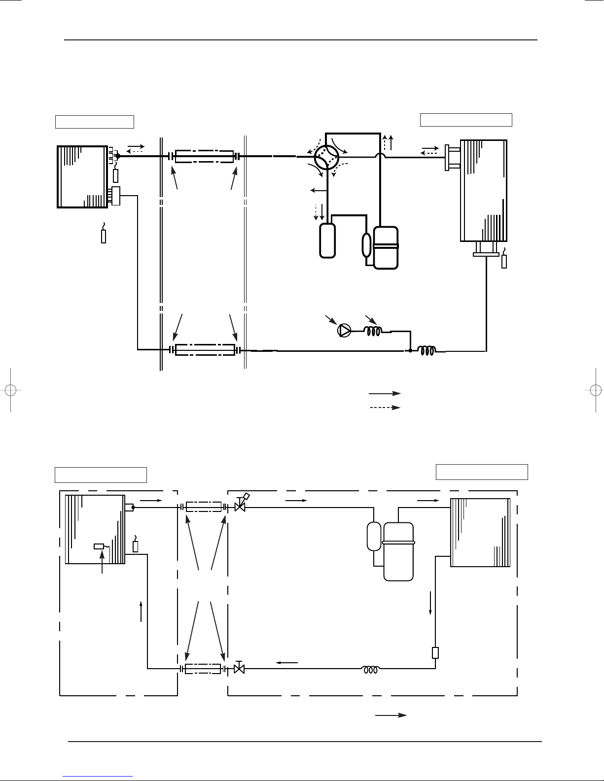
Heat Pump
Cooling Only
Refrigerating Cycle System
TCL Air Conditioner Service Manual
9
INDOOR UNIT
Indoor coil
Indoor
heat
exchanger
Room temperature
thermistor
thermistor
Distributor
Refrigerant pipe
(Option)
(with heat insulator)
Flared connection
Flared connection
Refrigerant pipe
(Option)
(with heat insulator)
Reversing valve
(4- way valve)
Accumulator
Check
valve
Compressor
Capillary tube
Capillary tube
OUTDOOR UNIT
Outdoor
heat
exchanger
Defrost
thermistor
Refrigerant flow in cooling or Defrosting
Refrigerant flow in heating
INDOOR UNIT
Indoor
heat
exchanger
Room temperature
thermistor
Indoor coil
thermistor
Refrigerant pipe
(Optional)
(with heat insulator)
Flared
connection
Refrigerant pipe
(Option)
(with heat insulator)
Stop valve
(with service port)
Stop valve
Compressor
Capillary tube
OUTDOOR UNIT
Outdoor
heat
exchanger
Strainer
Refrigerant flow in cooling
Page 10
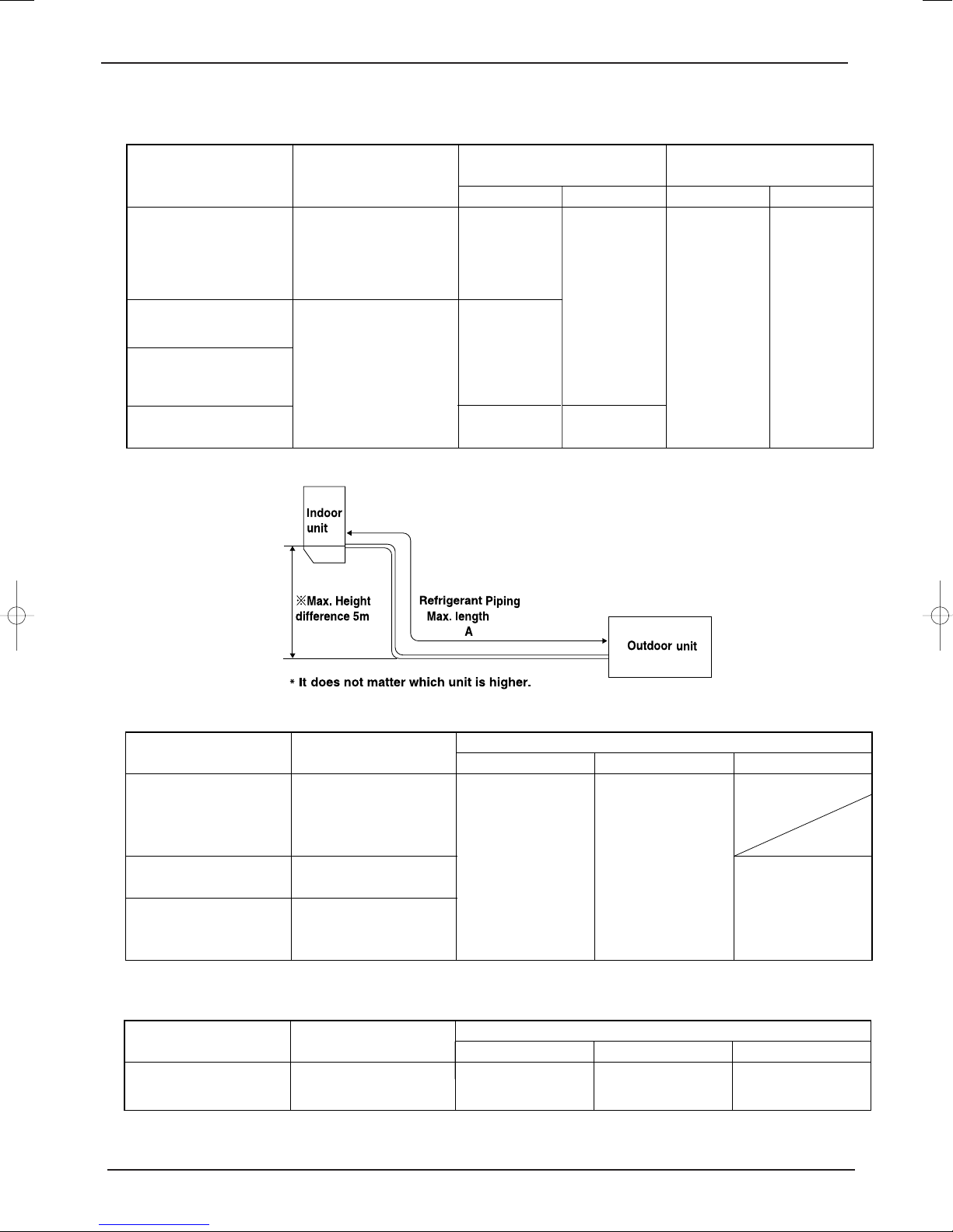
MAX. REFRIGERANT PIPING LENGTH
Models
Outdoor unit precharged
(up to 7m)
Refrigerant piping length (one way)
15m
240
7m
0
10m
90
24
K
10
TCL Air Conditioner Service Manual
Refrigerant piping
Models
07K
09K
Max. length : m
A
10
Piping size O.D : mm Length of connecting pipe : m
Gas
Liquid
Indoor unit
Outdoor unit
9.52
12K
18K
15
24K
MAX. HEIGHT DIFFERENCE
ADDITIONAL REFRIGERANT CHARGE(R-22 : g)
Models
07K
09K
12K
18
K
Outdoor unit precharged
(up to 7m)
see <<Specification>>
see <<Specification>>
see <<Specification>>
12.7
15.88
6.35
9.52
Refrigerant piping length (one way)
7m
0
10m
60
0.40
0
15m
160
see <<Specification>>
Calculation : Xg=20g/m ✕ (A-7)m
Calculation : Xg=30g/m ✕ (A-7)m
Page 11
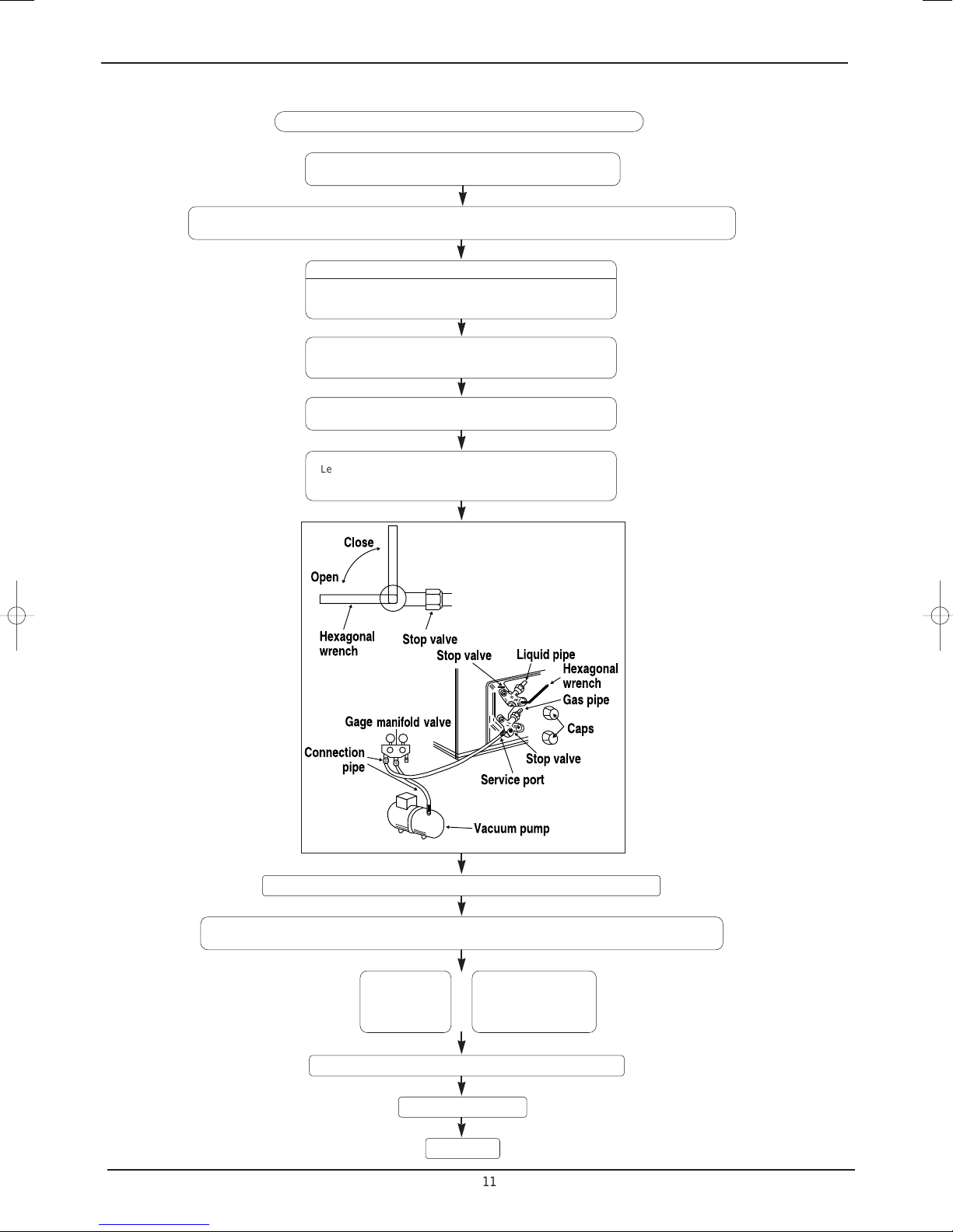
EVACUATION PROCEDURES(AIR PURGE)
11
TCL Air Conditioner Service Manual
Connect the refrigerant pipes (both the liquid and gas pipes)
between the indoor and the outdoor units.
Remove the service port cap of the stop valve on the side of the outdoor unit gas pipe.(The stop valve will not
work in its initial state fresh out of the factory (totally closed with cap on))
When vacuuming
Connect the gage manifold valve and the vacuum pump to
the service port of the stop valve on the liquid pipe side of the
outdoor unit.
Run the vacuum pump for more than 15 minutes and at this
time confirm that the pressure gage indicates – 0.1 Mpa.
Check the vacuum with the gage manifold valve, then close
the gage manifold valve, and stop the vacuum pump.
Leave it as it is for one or two minutes. Make sure the pointer
of the gage manifold valve remains in the same position.
Remove the gage manifold valve quickly from the service port of the stop valve.
After refrigerant pipes are connected and evacuated, fully open all stop valves on gas and liquid pipe sides.
Operating without fully opening lowers the performance and causes trouble.
Pipe length :
7m maximum
No gas charge
is needed
Tighten the cap to the service port to obtain the initial status.
Pipe length
exceeding 7m
Charge the prescribed
amount of gas
Retighten the cap.
Leak test
Page 12
12
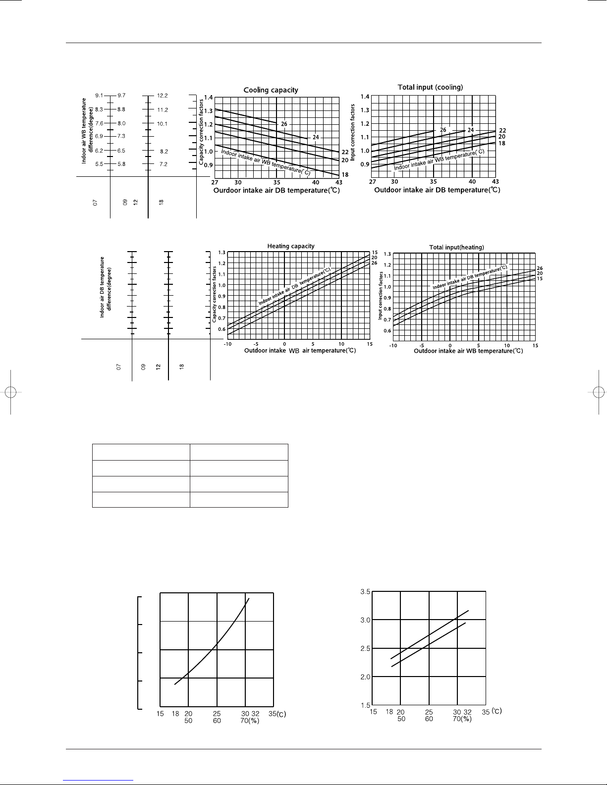
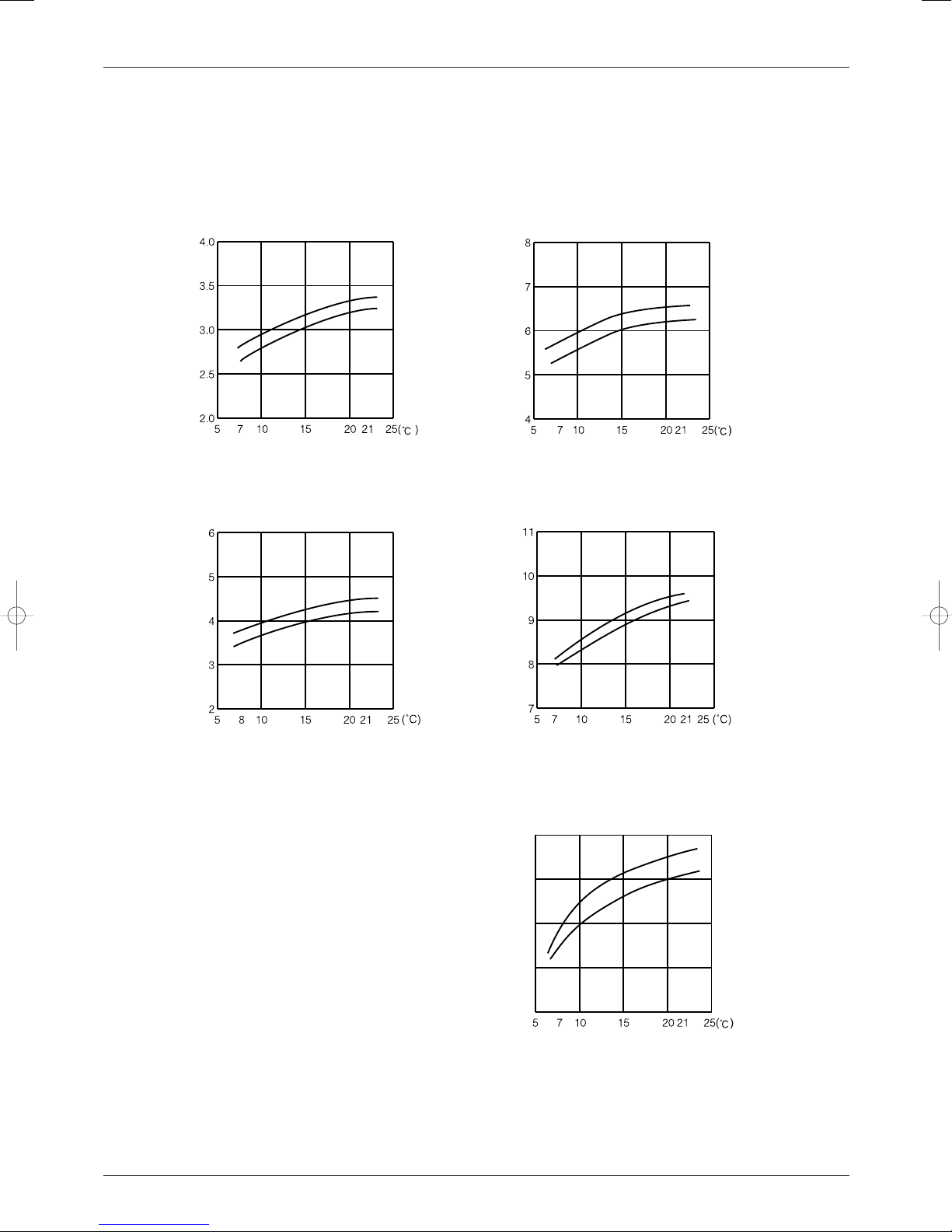
The standard data contained in these specifications apply only to the operation of the air conditioner under normal conditions,
Wet-and dry-bulb
thermometers
Wet-and dry-bulb
thermometers
TCL Air Conditioner Service Manual
PERFORMANCE CURVES
since operating conditions vary according to the areas where these units are installed. The following information has been provided to clarify the operating characteristics of the air conditioner under the conditions indicated by the performance curve.
(1) GUARANTEED VOLTAGE
Rated voltage : ±10% (198 ~ 264V
),50Hz
(2) AIR FLOW
Air flow should be set at MAX.
(3) MAIN READINGS
(1) Indoor intake air wet-bulb temperature : °CWB
(2) Indoor outlet air wet-bulb temperature : °CWB
(3) Outdoor intake air dry-bulb temperature : °CDB
(4) Total input: W
(5) Indoor intake air dry-bulb temperature : °CDB
(6) Outdoor intake air wet-bulb temperature : °CWB
(7) Total input : W
Indoor air wet/dry-bulb temperature difference on the left side of the chart on next page shows the difference between the
indoor intake air wet/dry-bulb temperature and the indoor outlet air wet/dry-bulb temperature for your reference at service.
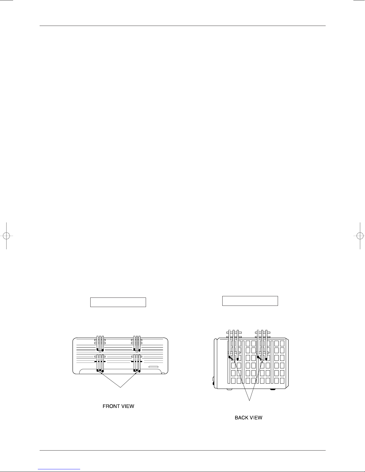
How to measure the indoor air wet-bulb/dry-bulb temperature difference
1. Attach at least 2 sets of wet-and dry-bulb thermometers to the indoor air intake as shown in the figure, and at least 2 sets
of wet-and dry-bulb thermometers to the indoor air outlet. The thermometers must be attached to the position where air
speed is high.
2. Attach at least 2 sets of wet-and dry-bulb thermometers to the outdoor air intake.
Cover the thermometers to prevent direct rays of the sun.
3. Check that the air filter is cleaned.
4. Open windows and doors of room.
5. Press the EMERGENCY OPERATION switch once(twice) to start the EMERGENCY COOL(HEAT) MODE.
6. When system stabilizes after more than 15 minutes, measure temperature and take an average temperature.
7. 10 minutes later, measure temperature again and check that the temperature does not change.
}
}
Cooling
Heating
INDOOR UNIT
OUTDOOR UNIT
Page 13
13
0.7
0.6
0.5
0.4
0.3
7
6
5
4
3
Outdoor low pressure
Ambient temperature(˚C)
Ambient humidity(%)
Ambient temperature(˚C)
Ambient humidity(%)
07K
07K
Outdoor unit current (A)
220V
240V
220/240V
(kgf/F•G)(MPa•G)
9.1
11.4
7.6
8.5
9.4
10.4
12.0
12.7
8.1
9.2
10.3
11.5
14.0
24
25.5
23.5
21.6
19.6
17.6
15.6
13.7
11.7
28.7
26.5
24.3
22.5
19.9
17.7
15.5
13.2
28.0
25.9
23.7
21.6
19.4
17.2
15.1
12.9
28.0
25.9
23.7
21.6
19.4
17.2
15.1
12.9
19.9
18.4
16.9
15.3
13.8
12.3
10.7
9.2
24
NOTE:The above curves are for the heating operation without any frost.
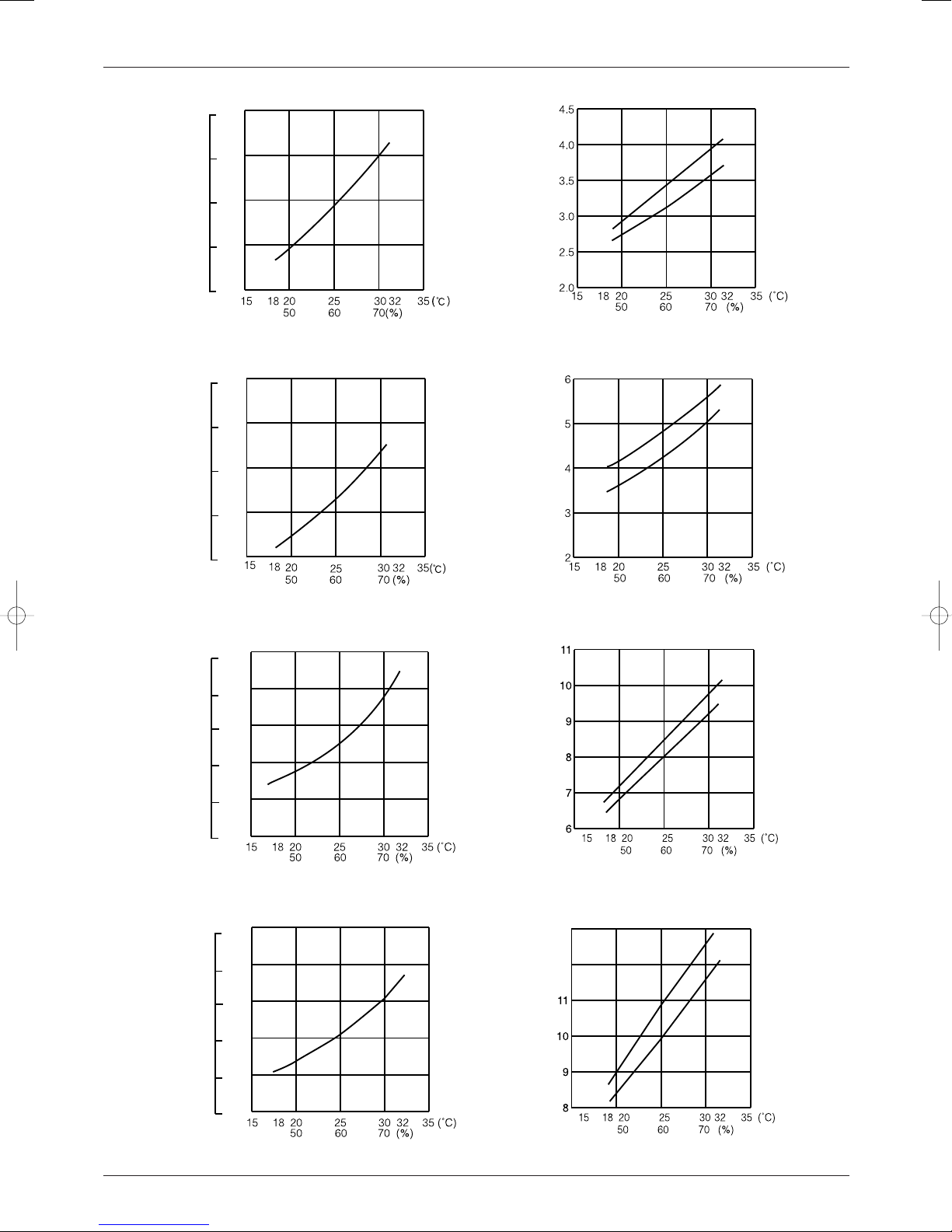
OUTDOOR LOW PRESSURE AND OUTDOOR UNIT CURRENT
COOL operation
① Both indoor and outdoor unit are under the same temperature/humidity condition.
➁ Air flow should be set at MAX.
Dry-bulb temperature
Relative humidity(%)
20
50
25
60
30 70
③ The unit of pressure has been changed to MPa on the international system of units(SI unit system).
The conversion factor is : 1(MPa • G) =10.2(kgf/
ff
• G)
TCL Air Conditioner Service Manual
Page 14
12K
12K
Outdoor low pressure
Ambient temperature(˚C)
Ambient humidity(%)
Ambient temperature(˚C)
Ambient humidity(%)
Outdoor unit current (A)
220V
240V
0.7
0.6
0.5
0.4
0.3
7
6
5
4
3
09K
09K
Outdoor low pressure
220V
240V
Ambient temperature(˚C)
Ambient humidity(%)
Ambient temperature(˚C)
Ambient humidity(%)
Outdoor unit current (A)
220/240V
220/240V
(kgf/F•G)(MPa•G)
(kgf/F•G)(MPa•G)
0.7
0.6
0.5
0.4
0.3
0.2
7
6
5
4
3
2
18K
18K
Outdoor low pressure
Ambient temperature(˚C)
Ambient humidity(%)
Ambient temperature(˚C)
Ambient humidity(%)
220V
240V
220/240V
Outdoor unit current (A)
(kgf/F•G)(MPa•G)
0.7
0.6
0.5
0.4
0.3
0.2
7
6
5
4
3
2
24K
Outdoor low pressure
Ambient temperature(˚C)
Ambient humidity(%)
220V
12
13
24K
Ambient temperature(˚C)
Ambient humidity(%)
220V
240V
Outdoor unit current (A)
(kgf/F•G)(MPa•G)
TCL Air Conditioner Service Manual
14
0.7
7
0.6
6
0.5
5
0.4
4
0.3
3
Page 15
HEAT operation
Condition indoor:Dry bulb temperature 20.0°C
Wet bulb temperature 14.5°C
Outdoor:Dry bulb temperature 7,15,20°C
Wet bulb temperature 6,12,14.5°C
18K
07K
12K
13
12
11
10
9
TCL Air Conditioner Service Manual
15
Outdoor unit current (A)
Ambient temperature(˚C)
09K
220V
240V
220V
240V
220V
240V
Outdoor unit current (A)
Ambient temperature(˚C)
220V
240V
Outdoor unit current (A)
Ambient temperature(˚C) Ambient temperature(˚C)
Outdoor unit current (A)
24K
220V
Outdoor unit current (A)
Ambient temperature(˚C)
240V
Page 16
16
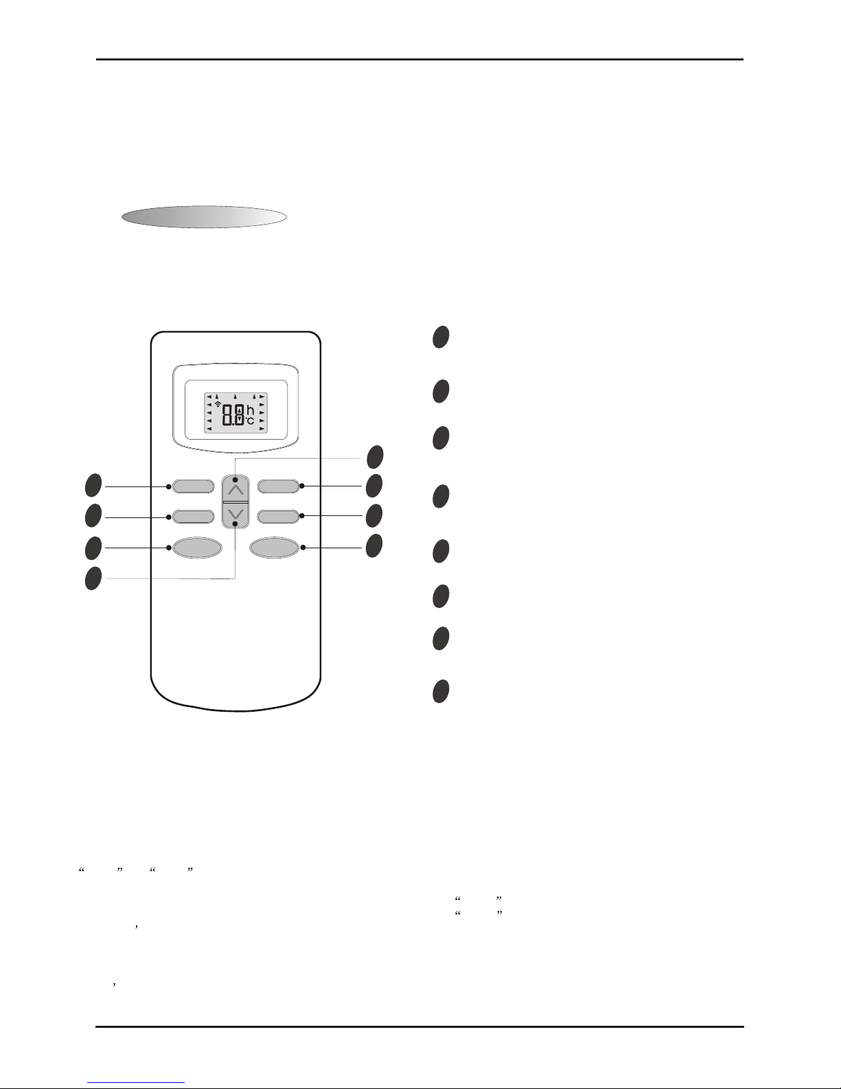
Note: Each mode and relevant function will be further specified in following pages.
SLEEP
FAN
TIMER
SWING
ON/OFF
MODE
MID
SWING
AUTO
DRY
FAN
HEAT
COOL
FEEL
SLEEP
TIMER ON
HIGH
LOW
TMIER OFF
The remote controller transmits signals to the system.
Remote controller
1
2
4
3
5
6
7
8
8
4
MODE button
FAN SPEED control button
UP button (TOO COOL button)
DOWN button (TOO WARM button)
ON/OFF button
SLEEP button
VANE control button
TIMER button
Used to select the type of operation mode: Feel,
Cooling, Dry, Fan and Heating(Only for Heat Pump).
Used to select the indoor fan motor speed:
Auto, High, Mid and Low.
Used to increase the set room temperature
and time.
Used to decrease the set room temperature
and time.
Used to set or cancel sleep mode operation.
Used to start and stop operation
when pressed.
Used to adjust airflow direction.
Used to select TIMER operation.
Remote controller
6
2
5
3
7
1
11
TCL Air Conditioner Service Manual
Operation Details
Remote Controller presetting
er presetting presetting as Cooling Only Air Conditioner or Heat Pump by
manufacturer.
Each time after the remote controller replace batteries or is energized, the arrowhead will flashes on the front of
Heat or Cool on LCD of the remote controller.
User can preset the remote controller type depending on the air conditioner type you have purchased as follows:
Press any button when the arrowhead flashes on the front of Cool , Cooling Only is set.
The remote controller is not
Press any button when the arrowhead flashes on the front of Heat , Heat Pump is set.
If you don t press any button within 10 seconds, the remote controller is preset as Heat Pump automatically.
Note :
If the air conditioner you purchased is a Cooling Only one, but you preset the remote controller as Heat Pump, it
doesn t bring any matter. But if the air conditioner you purchased is a Heat Pump one, and you preset the
remote controller as Cooling Only, then you CAN NOT preset the Heating operation with the remote controller.
Page 17
TCL Air Conditioner Service Manual
17
Elctronic Controller
1. Safety Control
(1) Time Delay Safety Control
3 minutes delay for compressor---The compressor is ceased for 3minutes to balance the pressure in the
refrigeration cycle in order to protect the compressor.
2 minutes delay for 4-way valve---The 4-way valve is ceased for 2 minutes to prevent the
refrigerant-gas abnormal noise when the HEATING operation is OFF or switch to the other operation
mode.
20 seconds delay for indoor fan--- When the assistant thermistor turn s off, the indoor fan operates in
low speed for 20 seconds to release the heat of indoor unit.
(2) Indoor Pipe Temperature Sensor Frost Prevention Control
When the indoor pipe temperature sensor reads 0℃ or below for 5 minutes, the indoor pipe temperature
sensor frost prevention control starts. The compressor and outdoor fan stop and indoor fa n operates at high
speed for 3 minutes. After that, if the indoor pipe temperature sensor reads less than 5℃ this control
prolonged until the indoor pipe temperature sensor reads 5℃ or more.
(3) High Temperature Protection Control
During HEATING operation, the outdoor fan motor and compressor are controlled by the indoor pipe
temperature to prevent the high temperature of compressor.
Outdoor fan OFF: 52℃
Outdoor fan ON:48℃
Compressor OFF:62℃
Compressor ON:48℃
2. “I Feel” Mode Operation
(1) When the “I Feel” mode is selected, the operation mode and initial set temperature are d etermined by the
initial room temperature at start-up of the operation except to turn off the air conditioner and operates it
again.
(2) If the mode is change to “I Feel” mode from other mode, the “I Feel” mode doesn’t operate until compressor
stop for more than 3 minutes.
In the “I Feel” mode , when the controller receives the up or down single of temperature, the set
temperature can adjust by 1
℃ upper or lower. The biggest you can adjust by 2℃ upper or lower.
3. “COOLING” Mode Operation
(1) When the COOLING mode is selected without setting temperature, the system will set the set temperature at
26
℃ automatically with the AUTO FAN speed.
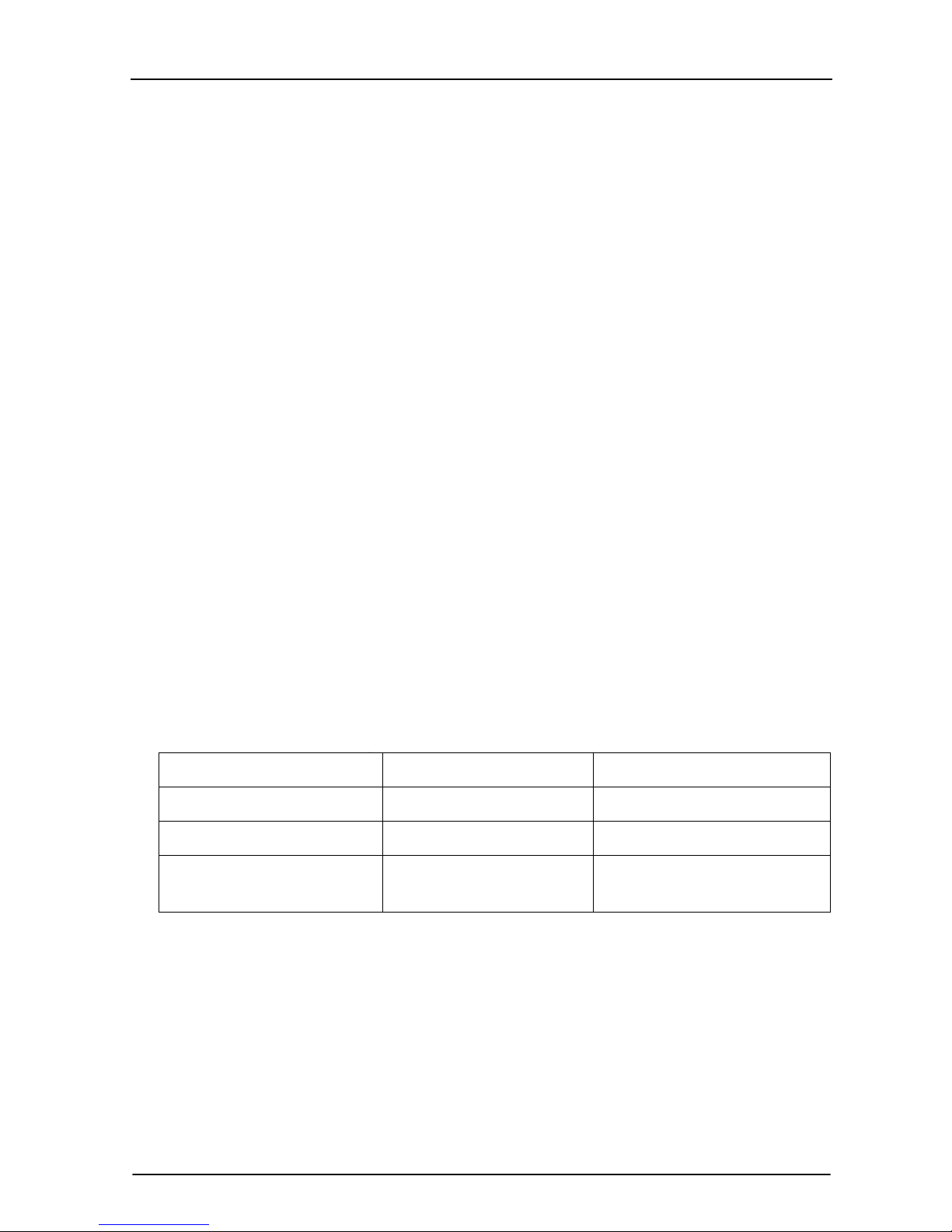
(2) When selecting the COOLING mode operation, the system will operate according to the setting by the
remote controller and the operation is as following:
Mode
Initial room temperature
COOLING
DRY
HEATING for Heat Pump Type
FAN for Cooling Only Type
26℃ or more
20℃ to 25 ℃
Less than 20℃
Initial set temperature
24℃
18℃
23℃
Page 18
TCL Air Conditioner Service Manual
18
Room Temp.
Set TEMP. +1
℃
Set TEMP. -1
℃
Time
More than 2 min More than 2 min More than 2 min More than 2 min More than 2 min
Indoor Fan Set Speed Set Speed Set Speed Set Speed Set Speed
Compressor ON OFF ON OFF ON
Outdoor Fan ON OFF ON OFF ON
4. “DRY” Mode Operation
(1) The system for DRY operation used the same refrigerant circle as the cooling circle.
(2) When the system operates in DRY mode ,at first it operates in cooling mode at 18
℃ for 3 minutes, and
then, the system operates in cooling mode with low speed that regards the temperature of the room
temperature sensor reads decrease 2℃ as the set temperature. During the course of this, the fan speed
setted operation is failing but the vane motor can be controlled.
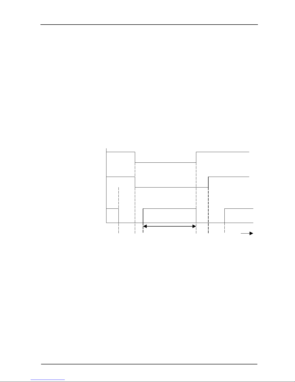
5. “HEATING” Mode Operation (Only available for Heat Pump)
(1) When the HEATING mode is selected without setting temperature, the system will set the temperature at 23
℃ automatically with the AUTO FAN speed.
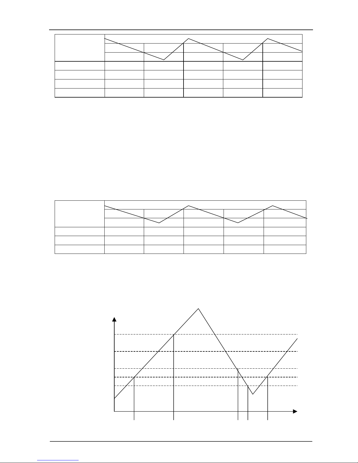
(2) When selecting the HEATING mode operation, the system will operate according to the setting by the
remote controller and the operation is as following:
Set T emp. +1℃
Set T emp. -1
℃
Room Temp.
Time
More than 2 min More than 2 min More than 2 min More than 2 min More than 2 min
Compressor ON OFF ON OFF ON
Outdoor fan ON OFF ON OFF ON
(3) In HEATING mode, the indoor fan motor is controlled by Cold Air Prevention Control.
(4) Cold Air Prevention Control
The function is intend to prevent cold air from being discharged when the heating operation starts or
when defrosting.
The indoor fan speed will be controlled as following:
The vane angle is at the angle C(100°).
34
℃
30
℃
27
℃
25
℃
23
℃
OFF UL Set Speed UL OFF UL
Indoor Pipe Temperature
Page 19
TCL Air Conditioner Service Manual
19
(5) Defrost
Defrosting of the outdoor heat exchange is controlled by the microprocessor with detection by the defrost
sensor.
Defrost starting conditions
When the conditions of a) or b) is satisfy, the defrosting operation starts.
a) Under the heating operation, the compressor cumulative operation time exceeds 50 minutes and the
temperature of the outdoor defrost sensor reads lower than -8
℃
b) Under the heating operation, the compressor cumulative operation time exceeds 50 minutes, if the
indoor pipe temperature sensor reads lower than 40
℃ continuously for 2minutes.
Note: If haven’t the outdoor pipe temperature sensor that use the condition b) to defrost, against
use the condition a).
Defrost terminating conditions
When the condition c) or d) is satisfy, the defrosting operation stops.
c) The outdoor defrost sensor reads 15
℃ or more.
d) The defrosting time exceeds 10 minutes.
Defrosting time chart
Outdoor Fan ON OFF ON
Revering Valve ON OFF ON
Compressor Relay ON OFF ON OFF ON
39S 5S Defrost Count MAX 12min 19S 15S t
(6) Assistant Thermistor Function
Assistant thermistor is add the thermitor of the electricity to rise the heating capacity automatically not
effected by the signal of the remote controller about assistant thermistor ON/OFF buttons.
1) When the condition all of A~G are satisfy, the assistant thermistor opens.
A. Under the heating operation, the compressor operates over than 3 minutes.
B. The indoor fan operates in normal.
C. The system operates not in defrosting.
D. The assistant thermistor turn off over than 30 seconds.
E. The set temperature is 3
℃ or more than the room temperature.
F. The room temperature sensor reads less than 22
℃.
G.
The indoor pipe temperature reads 43℃ or less.
2) When one of the conditions of A~E is satisfy, the assistant thermistor is off.
A. The compressor is turned off.
B. The room temperature sensor reads 24℃ or more.
C.
The indoor pipe temperature sensor reads 48℃ or more.
D.
The indoor fan is stopped.
6. “FAN” mode operation
Page 20
TCL Air Conditioner Service Manual
20
The indoor fan motor always turns on at the set speed and the vane motor turns on at the set fattle.
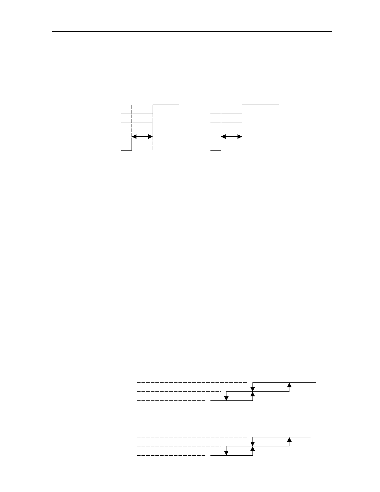
7. 4-way Valve contro
HEATING ON
COOLING/DRY OFF
The 4-way valve reverses for 5 seconds right before start-up of the compressor as following chart:
COOLING/DRY HEATING
Compressor
4-way Valve
5s 5s
Outdoor Fan
8. “SLEEP” mode
When the SLEEP button is pressed, the SLEEP mode is selected as following:
The indoor fan speed is set at the super low speed.
When selecting COOLING/DRY operation with SLEEP mode, the set te mperature will be raised by 1
℃ 1
hour later and by 2℃ 2 hour later.
When selecting HEATING operation with SLEEP mode, the set temperature will be dropped by 1℃ 1
hour later and 2℃ 2hour later.
After the System operates in SLEEP mode for 8 hours, it will stop automatically.
9. Fan motor control
(1) Rotational frequency feedback control
The indoor fan motor is equipped with a rotational frequency sensor, and outputs signal to the
microprocessor to feedback the rotational frequency. Comparing the cu rrent rotational frequency with the
target rotational frequency, the microprocessor adjusts fan motor electric to make the current rotational
frequency close to the target rotational frequency. With this control, when the fan speed is switched, the
rotational frequency changes smoothly.
(2) When the rotational frequency feedback signal has not output for 5 seconds (or when the microprocessor
can’t detect the signal for 5 seconds), the fan motor is regarded locked-up . Then the el ectric curren t to the
fan motor is shut off. 10 seconds later, the electric current is applied to the fan motor again. During the fan
motor lock-up, the POWER indicator lamp flashes on and off to show the fan motor abnormality.
10. Auto Fan Speed Control
(1) When the auto fan speed is selected, the indoor fan motor speed is automatically controlled by the room
temperature and the set temperature.
(2) In COOLING mode, the indoor fan motor operates as following:
Fan Speed
Hi
Me
Lo
Room temperature minus set temperature: 1℃ 2℃ 4℃
(3) In HEATING mode, the indoor fan motor operates as following;
Fan Speed
Hi
Mi
Lo
Room temperature minus set temperature 1
℃ 2℃ 4℃
Page 21

TCL Air Conditioner Service Manual
21
11. Auto Vane Operation Control
(1) Vane motor drive
The unit is equipped with a stepping motor for the vane. The rotating direction, speed and ang le of the
motor are controlled by pulse signal transmitted from indoor microprocessor.
(2) Positioning
The vane is once pressed to the vane stopper below to confirm the standard position and then set to the
desired angle. The positioning is decided as follow:
When the ON/OFF button is pressed.
When the vane control is change from AUTO to MANUAL.
When the SWING is finished.
When the test run starts.
When the power supply turns ON.
(3) The auto vane changes as follows by pressing the VANE CONTROL button.
(4) VANE AUTO mode
In vane auto mode, the microprocessor automatically determines the vane angle and operation to make the
optimum room-temperature distribution.
(5) SWING mode
When presses the SWING button, the vane swings.
12. TIMER Operation
How to set the timer
Press ON/OFF button to start the air conditioner.
Press TIMER CONTROL button for once in timer on--- SET the TIME of TIMER; press for second
time---START operation for SHUT OFF; press third time---CANCEL operation for TIMER.
Press TIMER CONTROL button for once in timer off---SET the TIME of TIMER; press for second
time---START operation for TURN ON; press for third time---CANCEL operation for TIMER.
Press UP and DOWN button to set the time, time setting is 30-minutes units.
After setting the timer, check that TIMER INDICATOR lamp of the indoor unit lights.
Press the ON/OFF button for the air conditioner operates in timer, the timer will be cancelled.
TIMER setting can be cancelled by power failure or breaker functioning.
13. EMERGENCY-TEST Operation
When the EMERGENCY Operation switch is press once, COOLING mode is selected and if in 3 seconds the
EMERGENCY Operation switch is pressed again, HEATING mode is selected. Then presses once again, the
unit switch off.
When the remote controller is missing, has failed or the batteries run down, press the EMERGENCY
Operation switch on the front of the indoor unit, The unit will start.
The first 30 minutes of operation will be the test run operation. The operation is for servicing in set mode. The
indoor fan runs at high speed and the system is in continuous operation. The vane motor is ON and the timer
is reset to normal.
After 30 minutes of test run operation the system shifts to AUTO COOLING/HEATING mode. and the indoor
fan runs in outomatic speed. The vane motor is on. The operation continues until the EMERGENCY
operation switch is pressed or a button on the remote controller is pressed, the normal operation will start.
NOTE: Do not press the EMERGENCY Operation switch during normal operation.
14. AUTO RESTART function (Option)
When the indoor unit is controlled with the remote con troller, the operation mode, set temperature, and the
fan speed are memorized by the indoor electric control PCB. The AUTO RESART function sets to work the
Page 22
TCL Air Conditioner Service Manual
22
moment power has restored after power failure. Then, the unit will restart automatically.
Auto-restart presetting:
The appliance is preset as no auto-restart function by manufacture. If Auto-restart function is needed, follow the
below step to active this function:
1) Make sure air conditioner is turned off.
2) Press down and hold the Emergency button (ON/OFF) on the indoor unit white turn on the air conditioner.
3) Keep pressing th e Emergency button for ov er 10s until three short beeps are heard.
Then Auto-restart function is activated. To cancel the Auto-restart function, repeat above procedure until four
short beeps are heard.
15. Failure Display and Handling
a) The failure of the resistance of heat sensitive:
When the resistance of heat sensitive reads the temperature is lower than -50
℃ o r over than 110℃ that
judge the heat sensitive is bad.
b) The Outdoor Protection Control
When the system checks the signal from outdoor of the voltage is 0V, the system delay 1second to start for
check the signal again, if checks the signal of the voltage is 0V too, that the system not to star, or operates on
normal.
c) Failure Display
When the controller is failure, the buzzer will voice long for three times, and displays the failure from the
failure lamp.
d) Failure Code
If have the digital pipe that display the failure code for digital pipe, or display for the run lamp.
Type of failure The lamp flash Display of digital pipe
The failure of room temperature sensor Once/cycle E1
The failure of indoor pipe temperature sensor Twice/cycle E2
Outdoor protection function 5 times/cycle E5
The failure of indoor fan 6 times/cycle E6
e) Failure Handling
When the room temperature sensor or the indoor pipe temperature sensor is failure, the system will be
shut off, the compressor will be OFF, and the outdoor fan and the indoor fan will be OFF. The system
doesn’t receive the signal of remoter controller except the signal of shut off it. When the failure
disappear, the controller can operate in normal mode. before this, presses the “ON/OFF” to start the
system, and it will operate in COOLING or HEATING for 30 minutes, and follows shut off. During
this, it displays the failure and the protction is failing. You must be give the electric ag ain to operate it.
In the failure, you can operate the FAN mode.
When the outdoor protects in the COOLING or DRY, the outdoor unit stops, the indoor fan operates in
set speed ; and in the HEATING, the outdoor unit stops, the assistant thermistor stops, the indoor fan
operates in cold air prevention control. The system doesn’t receive the signal of remoter controller
except the signal of shut off it. When the system check the voltage is 220V and the delay control is
finished, it operates at normal again.
When the indoor fan motor is failure, the compressor is stopped, the outdoor fan and indoor fan is
stopped and display the failure. The system doesn’t receive the signal of remoter controller except the
signal of shut off it.
f) Display Of The Control
In the display board the lamp from left is the POWER lamp(Red), the SLEEP lamp(Yellow), the TIMER
lamp(Yellow), the RUN lamp(Green).
(7) When gives the control electric, the buzzer voices a long for 0.3 second per cycle.
Page 23
TCL Air Conditioner Service Manual
23
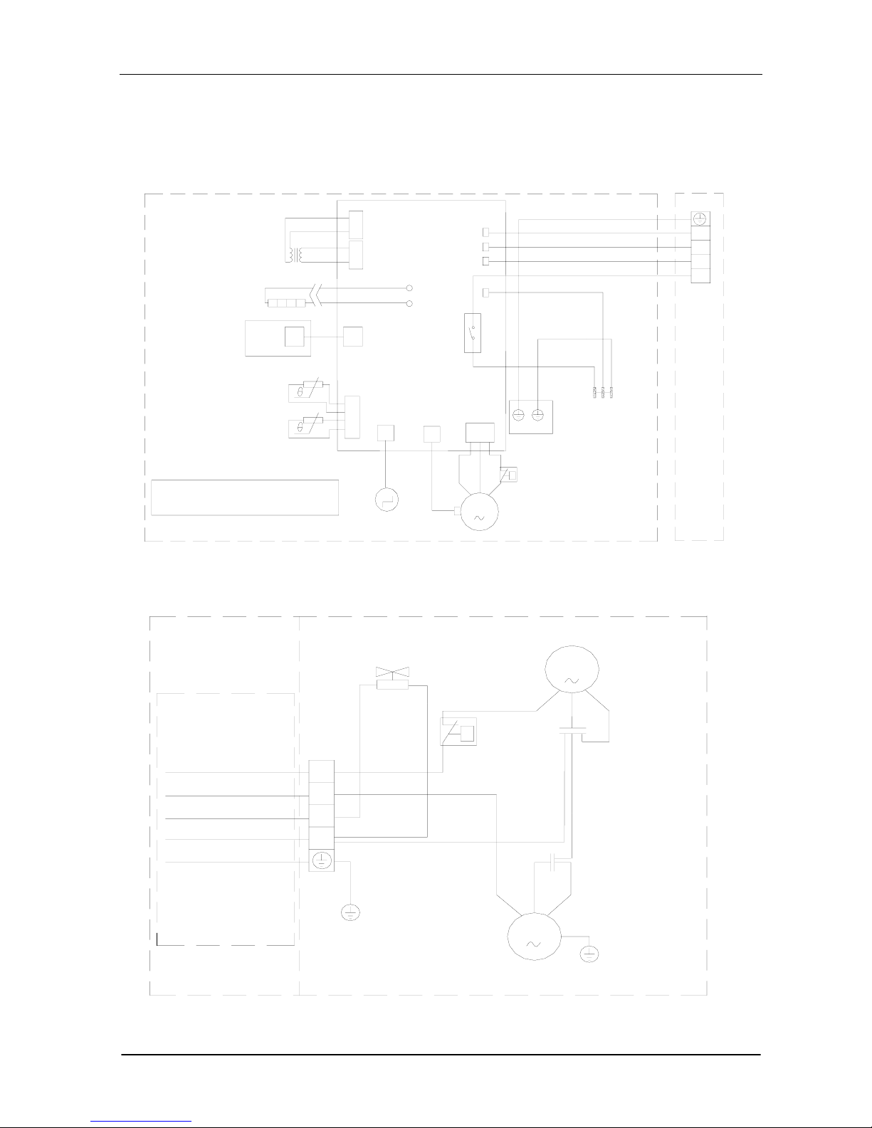
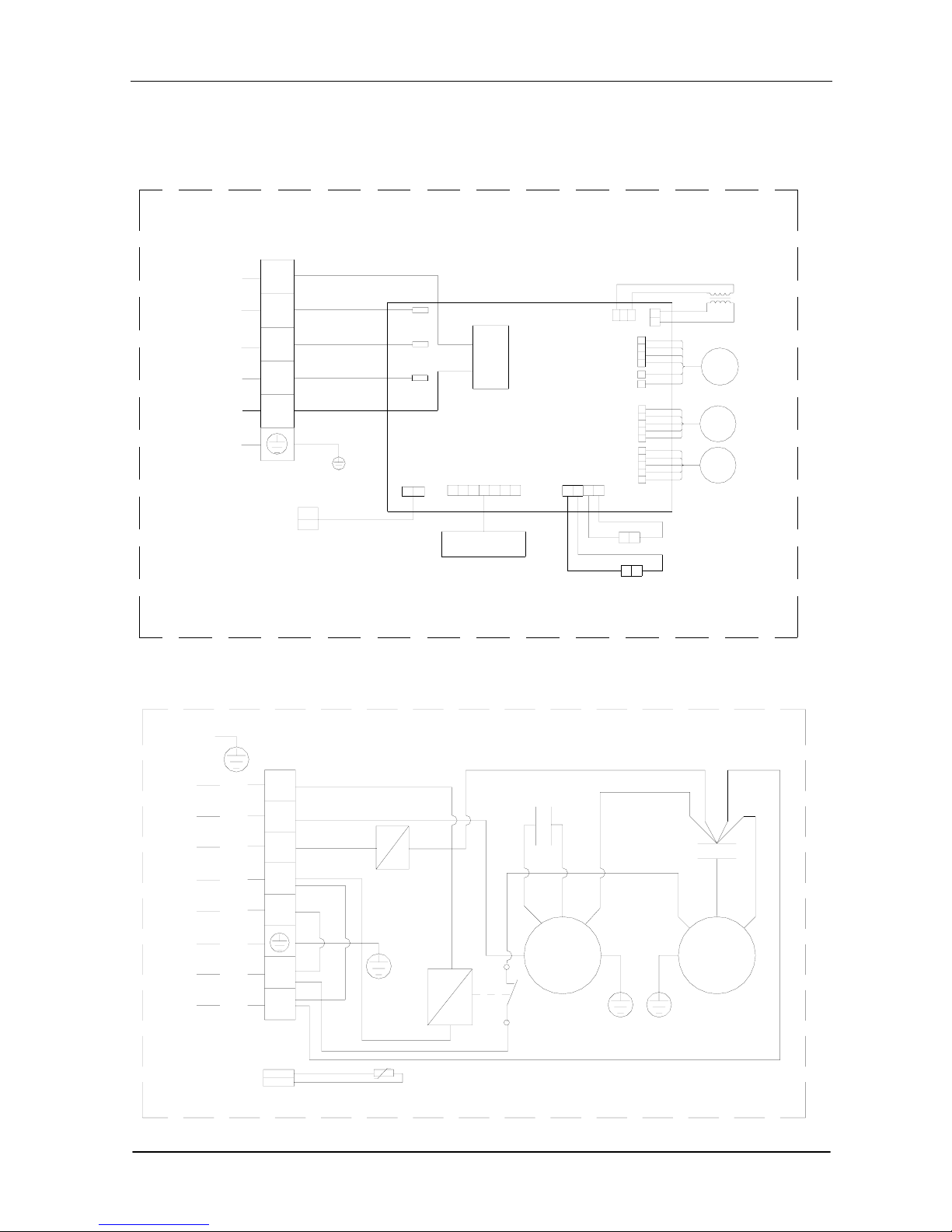
Wiring Diagram
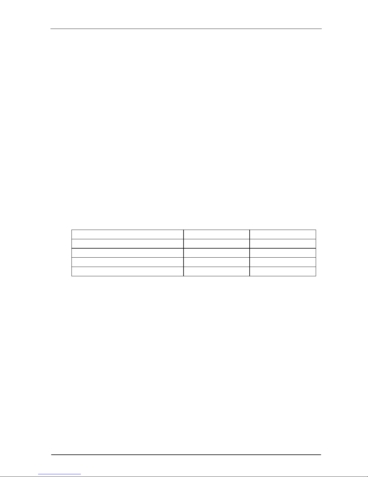
Mode No.: TAC-07CS/K, TAC-09CS/K, TAC-12CS/K
TAC-07CSC/K, TAC-09CSC/K, TAC-12CSC/K
INDOOR UNIT
Pipe Temp.Sensor
Room Temp.Sensor
Display PCB
transformer
protector
Fan Motor
Vane Motor
M
M
θ
Indoor Unit
Power supply
Brown
Yellow/Green
evaporator
K1
TH2
TH1
CN6
CN8
CN3
CN4
CN5
3
COM
CN1
CN2
4
N.O.
P2-2
P2-1
PCB
Brown
Blue
Yellow/Green
Outdoor
Unit
Blue
1
N
OUTDOOR UNIT
Brown
Blue
Yellow/Green
Compressor
White
Red
Blue
Blue
Black
White
Blue
Yellow/Green
Blue
Yellow/Green
Fan Motor
Outdoor UnitIndoor Unit
Fan Capacitor
Compressor Capacitor
Orange
θ
Protector
R(M)
C
S
CM
1
N
M
Page 24
TCL Air Conditioner Service Manual
24
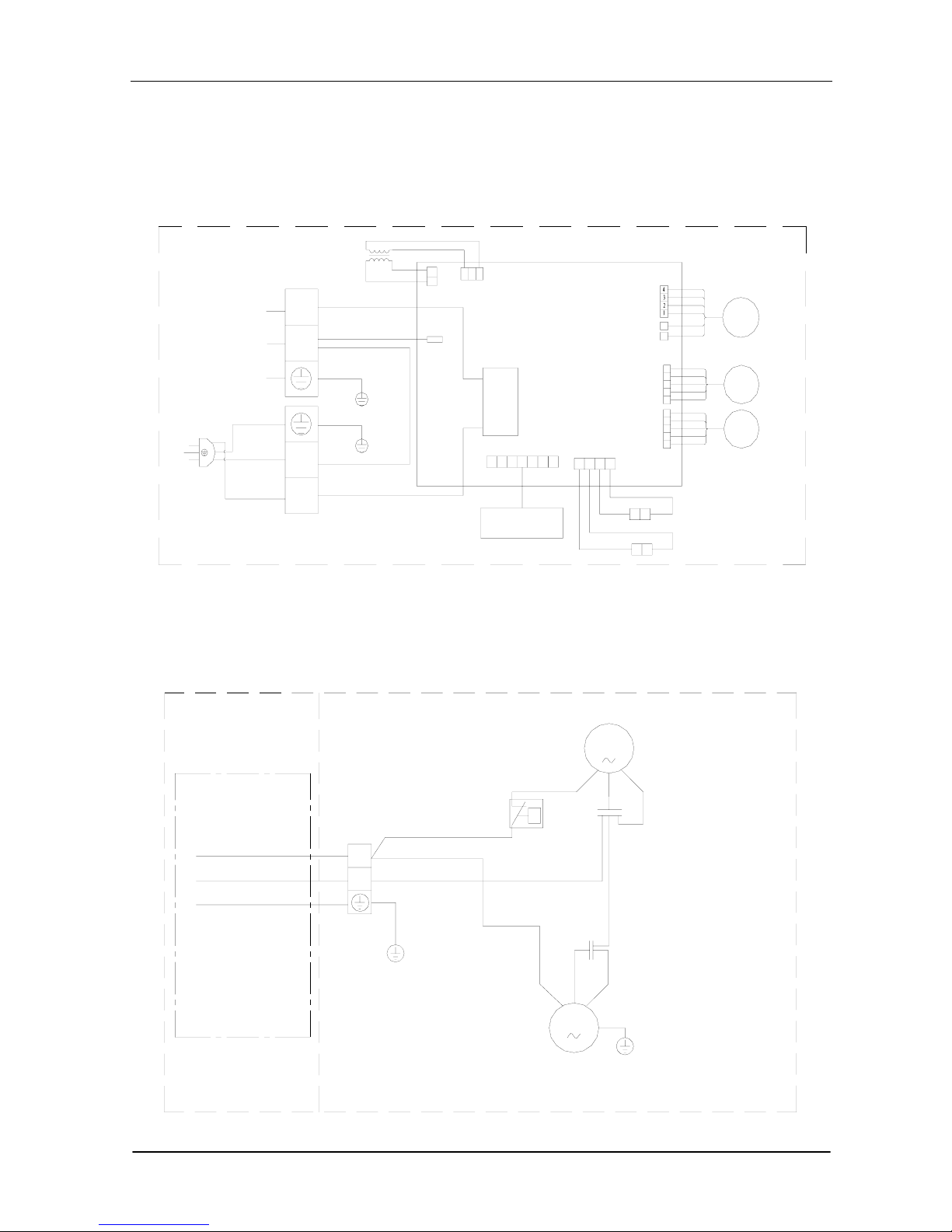
Mode No.: TAC-07CHS/K, TAC-09CHS/K, TAC-12CHS/K
TAC-07CHSC/K, TAC-09CHSC/K, TAC-12CHSC/K
INDOOR UNIT
Protecter
Fan Motor
Note: The thermistor is only with
the assistant thermistor type.
Vane Motor
Indoor Unit
Evaporator
Yellow/Green
Brown
Red
Yellow
Blue
Yellow/Green
Display PCB
Pipe Temp. sensor
Room Temp. sensor
Theimistor
Transformer
Power Supply
Brown
Blue
PCB
CN1
CN2
TH1
TH2
P2-1
P5
P4
P2-2
CN11
CN10
NO
K1
COM
4
3
CN8
CN6
CN5 CN4
CN3
M
M
θ
N
3
2
1
Outdoor
Unit
OUTDOOR UNIT
θ
Co m pressor
4-way Vane
White
CM
R
(M )
C
S
Blue
Co m pressor
Capacitor
Red
Protecter
Black
Brown(W hite)
Red
Y ello w
Blue
Yellow/Green
Blue
Yellow/Green
Outdoor UnitIndoor Unit
Fan Motor
Blue
Fan Capaciter
Blue
Yellow/Green
1
2
3
N
Blue
Blue
Orange
M
Page 25
TCL Air Conditioner Service Manual
25
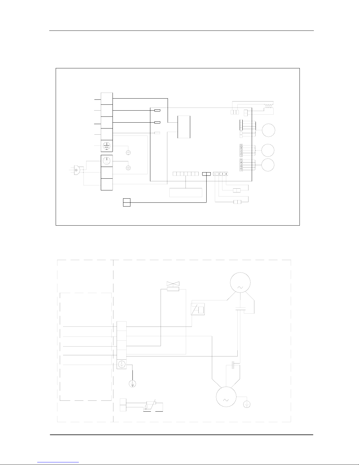
Mode No.: TAC-18CS/K, TAC-18CSC/K
INDOOR UNIT
PCB
Transformer
Brown
Blue
White
Blue
Yellow/Green
Yellow/Green
Yellow/Green
Yellow/Green
AC(N)
N.O
COM
Relay
1
N
N
L
Display PCB
Fan Motor
FM
SM
SM
Vane Motor
To The Outdoor
Room Temp. Sensor
Pipe Temp. Sensor
Blue
Brown
Blue
Brown
L
N
1234
1
2
3
4
5
1
2
3
4
5
OUTDOOR UNIT
Brown
Blue
Yellow/Green
Compressor
White
Red
Blue
Blue
Black
White
Blue
Yellow/Green
Blue
Yellow/Green
Fan Motor
Outdoor UnitIndoor Unit
Fan Capacitor
Compressor Capacitor
Orange
θ
Protector
R(M)
C
S
CM
1
N
M
Page 26
TCL Air Conditioner Service Manual
26
Mode No.: TAC-18CHS/K, TAC-18CHSC/K
INDOOR UNIT
1
N
L
N
N
To The Outdoor Unit
Yellow
Blue
PCB
2
3
White
Red
Brown
Yellow
Yellow/Green
To The Outdoor Sensor
Red
Blue
O.FAN
N.O
COM
VAL
AC(N)
Relay
Transformer
Fan Motor
Vane Motor
Room Temp. Sensor
Pipe Temp. Sensor
FM
SM
Display PCB
SM
Yellow/Green
Yellow/Green Yellow/Green
Blue
Blue
Brown
Brown
L
OUTDOOR UNIT
θ
Compressor
4-way Vane
White
CM
R
(M)
C
S
Blue
Compressor
Capacitor
Red
Protecter
Black
Brown(White)
Red
Yellow
Blue
Yellow/Green
Blue
Yellow/Green
Outdoor Unit
Indoor Unit
Fan Motor
Blue
Fan Capaciter
Blue
Yellow/Green
1
2
3
N
Blue
Blue
Orange
M
Pipe Temp. Sensor
Page 27
TCL Air Conditioner Service Manual
27
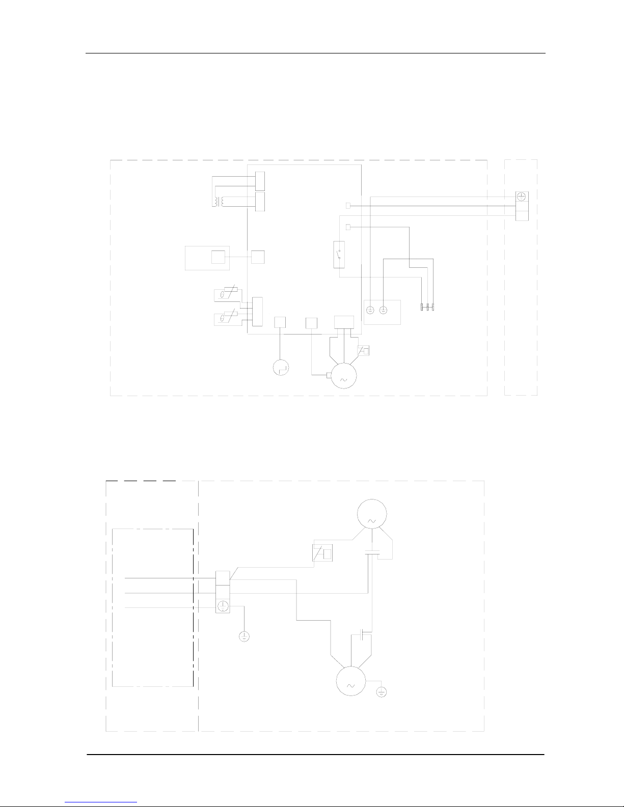
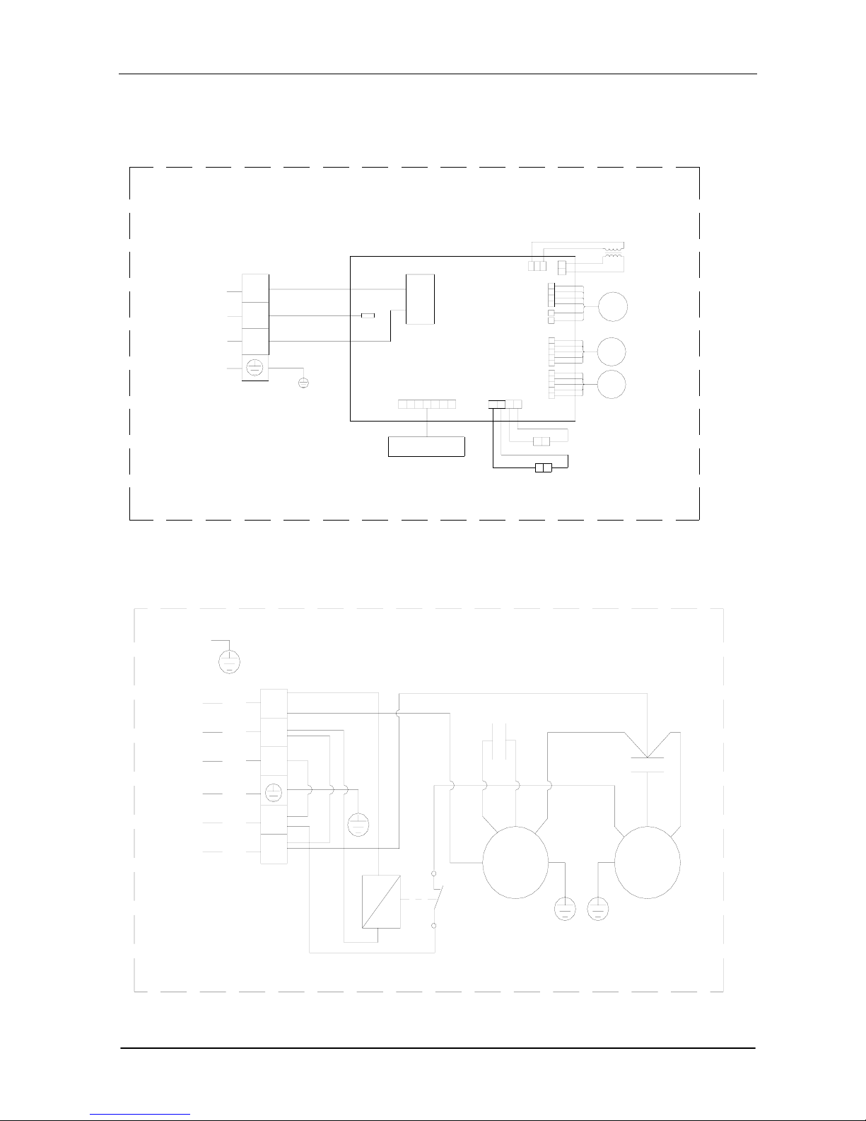
Mode No.: TAC-24CS/K, TAC-24CSC/K
INDOOR UNIT
Blue
N
Brown
Yellow/Green
L
White
White
1
PCB
Yellow/Green
Brown
Blue
N.O
COM
AC(N)
Relay
Transformer
FM
SM
Fan Motor
SM
Vane Motor
Display PCB
Room Temp. Sensor
Pipe Temp. Sensor
12
3
4
4
5
3
2
1
5
4
3
2
1
To Outdoor Unit
OUTDOOR UNIT
Conpressor
W hite
W hite
Yellow/Green
Blue
Brown
Yello w/Green
Brown
Blue
Blue
Brown
Brown
Brown
Yellow/Green
Red
W hite
Yellow
Red
C1
Blue
Blue
W hite
Fan Capacitor
Cap a cito r
Red
Blue
C2
To Power Supply
To Indoor Unit
Yellow/Green
Relay
Fan Motor
Conpressor
Motor
C
S
R
FM
CM
1
N
L
L
N
Page 28
TCL Air Conditioner Service Manual
28
Mode No.: TAC-24CHS/K, TAC-24CHSC/K
INDOOR UNIT
White
Red
White
Yellow
Blue
Brown
Yellow/Green
Red
Yellow
Blue
Brown
O.FAN
Yellow/Green
PCB
VAL
N.O
COM
Relay
AC(N)
To Outdoor Unit
Display PCB
Transformer
FM
SM
SM
Fan Motor
Vane Motor
Room Temp. Sensor
Pipe Temp. Sensor
To Outdoor Unit
1
2
3
N
L
12
3
4
5
1
2
3
4
5
4
3
2
1
OUTDOOR UNIT
White
White
Red
Yellow
Blue
Brown
Yellow/Green
White
White
Red
Brown
Yellow/Green
Brown
Blue
Blue
Brown
Blue
To Power Supply
To Indoor Unit
4-way Vane
Yellow
Red
C1
Fan Capacitor
Blue
Blue
Red
Compressor
Capacity
White
C2
Yellow/Green
Compressor
Blue
Motor
Fan Motor
Relay
Pipe Temp. Sensor
FM
FM
C
S
R
1
2
3
N
L
L
N
Yellow/Green
Page 29
TCL Air Conditioner Service Manual
29
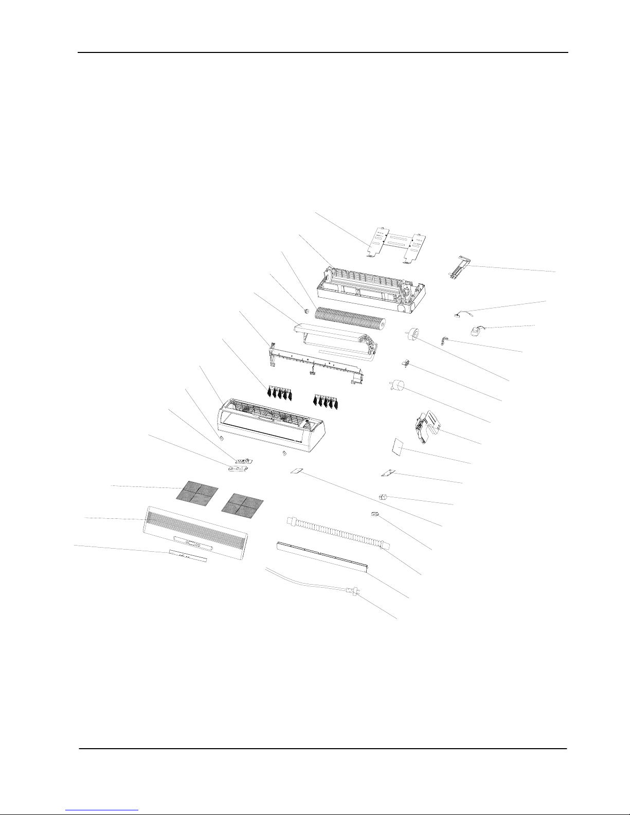
INDOOR UNIT
TAC-07CS/K,TAC-07CSH/K,TAC-07CSC/K,TAC-07CHSC/K,TAC-09CS/K,TAC-09CHS/K,TAC-09CSC/K,
TAC-09CHSC/K, TAC-12CS/K, TAC-12CHS/K, TAC-12CSC/K, TAC-12CHC/K,
1
2
3
5
14
6
7
8
9
10
15
16
17
18
19
20
21
22
23
24
25
26
27
11
12
13
4
28
29
30
Page 30
TCL Air Conditioner Service Manual
30
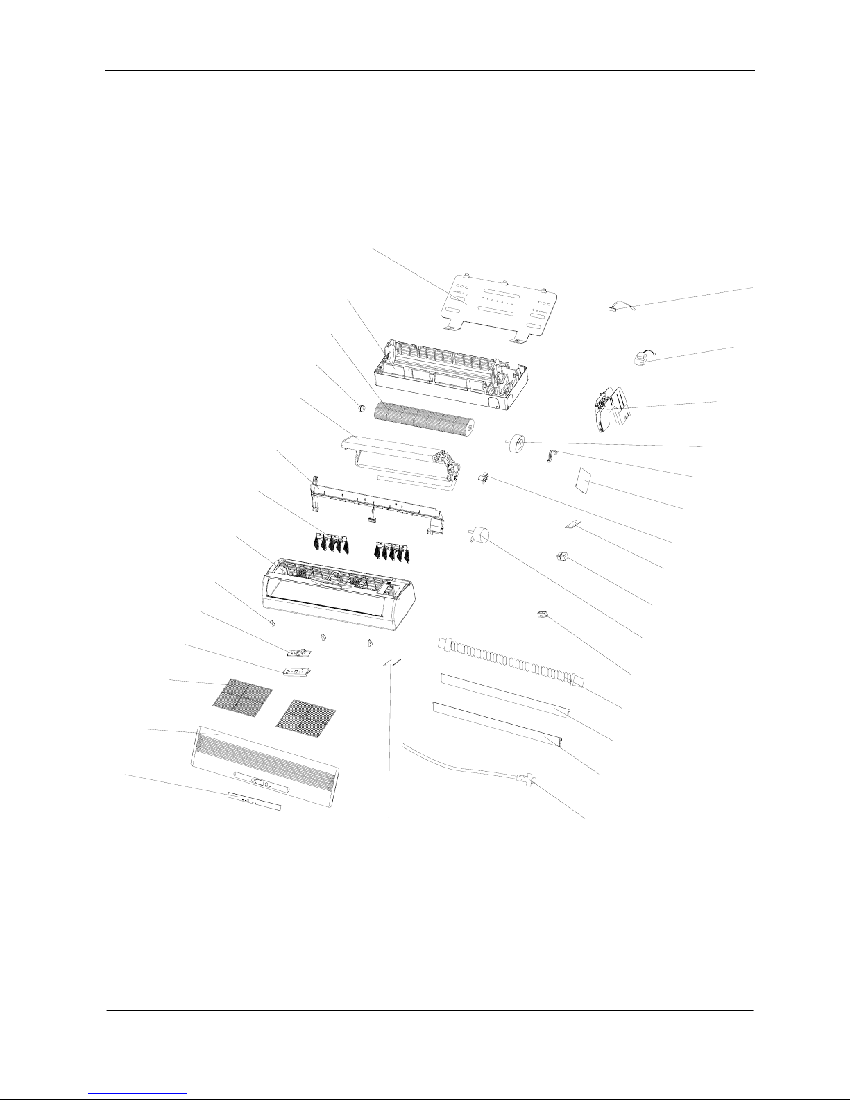
INDOOR UNIT
T A C-18CS/K, TAC-18CSC/K, TAC-18CHS/K, TAC-18CHSC/K
T A C-24CS/K, TAC-24CSC/K, TAC-24CHS/K, TAC-24CHSC/K
1
2
3
4
5
6
7
8
9
10
11
12
13
29
28
27
26
25
24
23
22
21
20
19
18
17
14
15
30
16
Page 31

TCL Air Conditioner Service Manual
31
Outdoor Unit: TAC-07CS/K, TAC-07CSC/K, TAC-09CS/K, TAC-09CSC/K, TAC-12CS/K,
TAC-12CSC/K, TAC-18CS/K, TAC-18CSC/K, TAC-24CS/K, TAC-24CSC/K
1
2
3
5
4
6
7
9
10
11
12
13
14
15
16
17
20
~28
8
18
19
Page 32

TCL Air Conditioner Service Manual
32
Outdoor Unit: TAC-07CHS/K, TAC-07CHSC/K, TAC-09CHS/K, TAC-09CHSC/K, TAC-12CHS/K
TAC-12CHSC/K, TAC-18CHS/K, TAC-18CHSC/K, TAC-24CHS/K, TAC-24CHSC/K
1
2
3
4
5
6
7
9
10
11
12
13
14
15
16
19~
28
8
17
18
Page 33

TCL Air Conditioner Service Manual
33
Parts List
Indoor Unit- TAC-07CS/K, TAC-09CS/K
No. Part No. Part Name Q’ty Remark
1 1080030003 Installation Plate 1
2 1210250103 Base 1
3 1070020017 Cross Fan 1
4 1070100010 Bearing Mount 1
5 1210230101 Evaporator 1
6 1070250102 Water Drainage Assembly 1
7 1070320105 Vertical Vane Assembly 2
8 1070250104 Face Frame 1
9 1070320112 Screw Cover 2
10 1090320102 Display PCB 1
11 1070320115 Display PCB Box 1
12 1070250106 Air Filter 2
13 1070251801 Front Panel 1
14 1070251001 Display PC Board Cover 1
15 1170120042 Power Supply Cord 1
16 1070250103 Vane 1
17 1070110008 Drainage Hose 1
18 1070040006 Electrical Box Cover 1
19 1070040004 Cable Clamp 1
20 1170200039 Terminal 1
21 1070250109 Terminal Fixing Board 1
22 1170020011 Vane Motor 1
23 1090250602 Main PCB 1
24 1110040001 Sensor Holder 1
25 1070320113 Electrical Box 1
26 1070320111 Indoor Motor Cover 1
27 1170030052 Indoor Motor 1
28 1170240001 Transformer 1
29 1170230001 Pipe Temp. Sensor & Room
Temp. Sensor Assembly
1
30 1070320101 In And Out Pipe Fixer 1
31 1090010071 Remote Controller 1
31 1073030303 Remote Controller Supporter 1
32 1190250204 Indoor Carton 1
33 1190060008 Left Foaming 1
34 1190060009 Right Foaming 1
Not shown in Explosion
view
Page 34

TCL Air Conditioner Service Manual
34
Indoor Unit- TAC-07CHS/K, TAC-09CHS/K
No. Part No. Part Name Q’ty Remark
1 1080030003 Installation Plate 1
2 1210250103 Base 1
3 1070020017 Cross Fan 1
4 1070100010 Bearing Mount 1
5 1210230101 Evaporator 1
6 1070250102 Water Drainage Assembly 1
7 1070320105 Vertical Vane Assembly 2
8 1070250104 Face Frame 1
9 1070320112 Screw Cover 2
10 1090320102 Display PCB 1
11 1070320115 Display PCB Box 1
12 1070250106 Air Filter 1
13 1070251801 Front Panel 2
14 1070251001 Display PC Board Cover 1
15 1170120042 Power Supply Cord 1
16 1070250103 Vane 1
17 1070110008 Drainage Hose 1
18 1070040006 Electrical Box Cover 1
19 1070040004 Cable Clamp 1
20 1170200040 Terminal 1
21 1070250109 Terminal Fixing Board 1
22 1170020011 Vane Motor 1
23 1090250202 Main PCB 1
24 1110040001 Sensor Holder 1
25 1070320113 Electrical Box 1
26 1070320111 Indoor Motor Cover 1
27 1170030052 Indoor Motor 1
28 1170240001 Transformer 1
29 1170230001 Pipe Temp. Sensor & Room
Temp. Sensor Assembly
1
30 1070320101 In And Out Pipe Fixer 1
31 1090010071 Remote Controller 1
31 1073030303 Remote Controller Supporter 1
32 1190250204 Indoor Carton 1
33 1190060008 Left Foaming 1
34 1190060009 Right Foaming 1
Not shown in Explosion
view
Page 35

TCL Air Conditioner Service Manual
35
Indoor Unit- TAC-07CSC/K , TAC-09CSC/K
No. Part No. Part Name Q’ty Remark
1 1080030008 Installation Plate 1
2 1210320107 Base 1
3 1070020016 Cross Fan 1
4 1070100010 Bearing Mount 1
5 1210320601 Evaporator 1
6 1070320103 Water Drainage Assembly 1
7 1070320105 Vertical Vane Assembly 2
8 1070320107 Face Frame 1
9 1070320112 Screw Cover 2
10 1090320102 Display PCB 1
11 1070320115 Display PCB Box 1
12 1070320109 Air Filter 2
13 1070321501 Front Panel 1
14 1070251001 Display PC Board Cover 1
15 1170120047 Power Supply Cord 1
16 1070320104 Vane 1
17 1070110008 Drainage Hose 1
18 1070040006 Electrical Box Cover 1
19 1070040004 Cable Clamp 1
20 1170200039 Terminal 1
21 1070250109 Terminal Fixing Board 1
22 1170020011 Vane Motor 1
23 1090320102 Main PCB 1
24 1110040001 Sensor Holder 1
25 1070320113 Electrical Box 1
26 1070320111 Indoor Motor Cover 1
27 1170030047 Indoor Motor 1
28 1170240001 Transformer 1
29 1170230001 Pipe Temp. Sensor & Room
Temp. Sensor Assembly
1
30 1070320101 In And Out Pipe Fixer 1
31 1090010071 Remote Controller 1
31 1073030303 Remote Controller Supporter 1
32 1190350102 Indoor Carton 1
33 1190060005 Left Foaming 1
34 1190060006 Right Foaming 1
Not shown in Explosion
view
Page 36

TCL Air Conditioner Service Manual
36
Indoor Unit- TAC-07CHSC/K, TAC-09CHSC/K
No. Part No. Part Name Q’ty Remark
1 1080030008 Installation Plate 1
2 1210320107 Base 1
3 1070020016 Cross Fan 1
4 1070100010 Bearing Mount 1
5 1210320601 Evaporator 1
6 1070320103 Water Drainage Assembly 1
7 1070320105 Vertical Vane Assembly 2
8 1070320107 Face Frame 1
9 1070320112 Screw Cover 2
10 1090320102 Display PCB 1
11 1070320115 Display PCB Box 1
12 1070320109 Air Filter 2
13 1070321501 Front Panel 1
14 1070251001 Display PC Board Cover 1
15 1170120047 Power Supply Cord 1
16 1070320104 Vane 1
17 1070110008 Drainage Hose 1
18 1070040006 Electrical Box Cover 1
19 1070040004 Cable Clamp 1
20 1170200040 Terminal 1
21 1070250109 Terminal Fixing Board 1
22 1170020011 Vane Motor 1
23 1090320103 Main PCB 1
24 1110040001 Sensor Holder 1
25 1070320113 Electrical Box 1
26 1070320111 Indoor Motor Cover 1
27 1170030047 Indoor Motor 1
28 1170240001 Transformer 1
29 1170230001 Pipe Temp. Sensor & Room
Temp. Sensor Assembly
1
30 1070320101 In And Out Pipe Fixer 1
31 1090010071 Remote Controller 1
31 1073030303 Remote Controller Supporter 1
32 1190350102 Indoor Carton 1
33 1190060005 Left Foaming 1
34 1190060006 Right Foaming 1
Not shown in Explosion
view
Page 37

TCL Air Conditioner Service Manual
37
Indoor Unit- TAC-12CS/K, TAC-12CSC/K
No. Part No. Part Name Q’ty Remark
1 1080030008 Installation Plate 1
2 1210320107 Base 1
3 1070020016 Cross Fan 1
4 1070100010 Bearing Mount 1
5 1210320601 Evaporator 1
6 1070320103 Water Drainage Assembly 1
7 1070320105 Vertical Vane Assembly 2
8 1070320107 Face Frame 1
9 1070320112 Screw Cover 2
10 1090320102 Display PCB 1
11 1070320115 Display PCB Box 1
12 1070320109 Air Filter 2
13 1070321501 Front Panel 1
14 1070251001 Display PC Board Cover 1
15 1170120047 Power Supply Cord 1
16 1070320104 Vane 1
17 1070110008 Drainage Hose 1
18 1070040006 Electrical Box Cover 1
19 1070040004 Cable Clamp 1
20 1170200039 Terminal 1
21 1070250109 Terminal Fixing Board 1
22 1170020011 Vane Motor 1
23 1090320102 Main PCB 1
24 1110040001 Sensor Holder 1
25 1070320113 Electrical Box 1
26 1070320111 Indoor Motor Cover 1
27 1170030047 Indoor Motor 1
28 1170240001 Transformer 1
29 1170230001 Pipe Temp. Sensor & Room
Temp. Sensor Assembly
1
30 1070320101 In And Out Pipe Fixer 1
31 1090010071 Remote Controller 1
31 1073030303 Remote Controller Supporter 1
32 1190350102 Indoor Carton 1
33 1190060005 Left Foaming 1
34 1190060006 Right Foaming 1
Not shown in Explosion
view
Page 38

TCL Air Conditioner Service Manual
38
Indoor Unit- TAC-12CHS/K , TAC-12CHSC/K
No. Part No. Part Name Q’ty Remark
1 1080030008 Installation Plate 1
2 1210320107 Base 1
3 1070020016 Cross Fan 1
4 1070100010 Bearing Mount 1
5 1210320601 Evaporator 1
6 1070320103 Water Drainage Assembly 1
7 1070320105 Vertical Vane Assembly 2
8 1070320107 Face Frame 1
9 1070320112 Screw Cover 2
10 1090320102 Display PCB 1
11 1070320115 Display PCB Box 1
12 1070320109 Air Filter 2
13 1070321501 Front Panel 1
14 1070251001 Display PC Board Cover 1
15 1170120047 Power Supply Cord 1
16 1070320104 Vane 1
17 1070110008 Drainage Hose 1
18 1070040006 Electrical Box Cover 1
19 1070040004 Cable Clamp 1
20 1170200040 Terminal 1
21 1070250109 Terminal Fixing Board 1
22 1170020011 Vane Motor 1
23 1090320103 Main PCB 1
24 1110040001 Sensor Holder 1
25 1070320113 Electrical Box 1
26 1070320111 Indoor Motor Cover 1
27 1170030047 Indoor Motor 1
28 1170240001 Transformer 1
29 1170230001 Pipe Temp. Sensor & Room
Temp. Sensor Assembly
1
30 1070320101 In And Out Pipe Fixer 1
31 1090010071 Remote Controller 1
31 1073030303 Remote Controller Supporter 1
32 1190350102 Indoor Carton 1
33 1190060005 Left Foaming 1
34 1190060006 Right Foaming 1
Not shown in Explosion
view
Page 39

TCL Air Conditioner Service Manual
39
Indoor Unit- TAC-18CS/K ,TAC-18CSC/K , TAC-24CS/K , TAC-24CSC/K
No. Part No. Part Name Q’ty Remark
1 1080030001 Installation Plate 1
2 1073090101 Base 1
3 1070020014 Cross Fan 1
4 1070100010 Bearing Mount 1
5 1213090106 Evaporator 1
6 1073090104 Water Drainage Assembly 1
7 1073090106 Vertical Vane Assembly 2
8 1073090110 Face Frame 1
9 1073090111 Screw Cover 3
10 1093090102 Display PCB 1
11 1073090126 Display PCB Box 1
12 1073090112 Air Filter 2
13 1070500205 Front Panel 1
14 1070500208 Display PCB Cover 1
15 1073090122 Electrical Box Cover 1
16 1170120006 Power Supply Cord 1
17 1073090108 Vane A 1
18 1073090125 Vane B 1
19 1070110008 Drainage Hose 1
20 1070040003 Cable Clamp 2
21 1170020011 Vane Motor 1
22 1170200038 Terminal 2
23 1083090108 Terminal Fixing Board 1
24 1110040001 Sensor Holder 1
25 1093090201 Main PCB 1
26 1073090120 Indoor Motor Cover 1
27 1170030045 Indoor Motor 1
28 1093090201 Electrical Box 1
29 1173090107 Transformer 1
30 1170230001 Pipe Temp. Sensor & Room
Temp. Sensor Assembly
1
31 1090010071 Remote Controller 1
31 1073030303 Remote Controller Supporter 1
32 1130120008 Indoor Carton 1
33 1073030303 Left Foaming 1
34 1190250204 Right Foaming 1
35 1190060002 Middle Pasteboard Supporter 1
36 1190060021 Middle Foaming Supporter 1
Not shown in Explosion
view
Page 40

TCL Air Conditioner Service Manual
39
Indoor Unit- TAC-18CHS/K,TAC-18CHSC/K, TAC-24CHS/K, TAC-24CHSC/K
No. Part No. Part Name Q’ty Remark
1 1080030001 Installation Plate 1
2 1073090101 Base 1
3 1070020014 Cross Fan 1
4 1070100010 Bearing Mount 1
5 1213090106 Evaporator 1
6 1073090104 Water Drainage Assembly 1
7 1073090106 Vertical Vane Assembly 2
8 1073090110 Face Frame 1
9 1073090111 Screw Cover 3
10 1093090102 Display PCB 1
11 1073090126 Display PCB Box 1
12 1073090112 Air Filter 2
13 1070500205 Front Panel 1
14 1070500208 Display PCB Cover 1
15 1073090122 Electrical Box Cover 1
16 1170120006 Power Supply Cord 1
17 1073090108 Vane A 1
18 1073090125 Vane B 1
19 1070110008 Drainage Hose 1
20 1070040003 Cable Clamp 2
21 1170020011 Vane Motor 1
22 1170200040 Terminal 2
23 1083090108 Terminal Fixing Board 1
24 1110040001 Sensor Holder 1
25 1093090101 Main PCB 1
26 1073090120 Indoor Motor Cover 1
27 1170030045 Indoor Motor 1
28 1093090201 Electrical Box 1
29 1173090107 Transformer 1
30 1170230001 Pipe Temp. Sensor & Room
Temp. Sensor Assembly
1
31 1090010071 Remote Controller 1
31 1073030303 Remote Controller Supporter 1
32 1130120008 Indoor Carton 1
33 1073030303 Left Foaming 1
34 1190250204 Right Foaming 1
35 1190060002 Middle Pasteboard Supporter 1
36 1190060021 Middle Foaming Supporter 1
Not shown in Explosion
view
Page 41

TCL Air Conditioner Service Manual
40
Outdoor Unit- TAC-07CS/K, TAC-09CS/K
No. Part No. Part Name Q’ty Remark
1 1083510901 Grille 1
Optional
2 1080050016 Top Cover 1
3 1210250112 Condenser 1
4 1080050015 Outdoor Motor Supporter 1
5 1170040062 Outdoor Motor 1
6 1070030006 Propeller Fan 1
7 1080050012 Left Plate 1
8 1080050018 Front Plate 1
9 1080050019 Fan Guard 1
10 1210250101 Capillary Assembly 1
11 --------------- Compressor and its Accessories 1
12 1120250608 Discharge Pipe 1
13 1123521402 Suction Pipe 1
14 1213530414 Base 1
15 1120120008 Two-way Valve 1
16 1080050014 Valve Supporter 1
17 1120130011 Three-way Valve 1
18 1080050013 Right Plate 1
19 1073521301 Electrical Box Cover 1
20 1080020001 Electrical Parts Box 1
21 1080010002 Capacitor Strip 1
22 1170100014 Compressor Capacitor 1
23 1170100031 Fan Motor Capacitor 1
24 1170200019 Terminal 1
25 1070040002 Cable Clamp(φ7) 1
26 1173570501 Compressor Power Supply
Wiring
1
27 1173570502 Earthing Wiring 1
28 1190070014 Base Carton 1
29 1190250201 Cabinet Carton 1
30 1190070016 Base Foaming 1
31 1190070015 Cover Forming 1
Not shown in the Explosion
view.
Page 42

TCL Air Conditioner Service Manual
41
Outdoor Unit- TAC-07CSC/K, TAC-09CSC/K
No. Part No. Part Na me Q’ty Remark
1 1083510901 Grille 1
Optional
2 1080050011 Top Cover 1
3 1210350207 Condenser 1
4 1080050004 Outdoor Motor Supporter 1
5 1170040059 Outdoor Motor 1
6 1070030012 Propeller Fan 1
7 1080050012 Left Plate 1
8 1080050009 Front Plate 1
9 1080320112 Fan Guard 1
10 1210250101 Capillary Assembly 1
Consist The Filter For Dry
11 --------------- Compressor and its Accessories 1
12 1120250608 Discharge Pipe 1
13 1123521402 Suction Pipe 1
14 1210500106 Base 1
15 1120120017 Two-way Valve 1
16 1080050003 Valve Supporter 1
17 1120130025 Three-way Valve 1
18 1080050002 Right Plate 1
19 107351103 Electrical Box Cover 1
20 1080020001 Electrical Parts Box 1
21 1080010006 Capacitor Strip 1
22 1170100007 Compressor Capacitor 1
23 1170100027 Fan Motor Capacitor 1
24 1170200019 Terminal 1
25 1070040002 Cable Clamp1(φ7) 1
26 1173570501 Compressor Power Supply
Wiring
1
27 1173570502 Earthing Wiring 1
28 1190070020 Base Carton 1
29 1190070002 Cabinet Carton 1
30 1190070022 Base Foaming 1
31 1190070021 Cover Forming 1
Not shown in the Explosion
view.
Page 43

TCL Air Conditioner Service Manual
42
Outdoor Unit- TAC-07CHS/K , TAC-09CHS/K
No. Part No. Part Na me Q’ty Remark
1 1083510901 Grille 1
2 1080050016 Top Cover 1
3 1210250112 Condenser 1
4 1080050015 Outdoor Motor Supporter 1
5 1170040062 Outdoor Motor 1
6 1070030006 Propeller Fan 1
7 1080050012 Left Plate 1
8 1080050018 Front Plate 1
9 1080050019 Fan Guard 1
10 1213530404 4-way Assembly 1
11 --------------- Compressor and its Accessories 1
12 1120250608 Discharge Pipe 1
13 1123521402 Suction Pipe 1
14 1213530414 Base 1
15 1120120008 Two-way Valve 1
16 1080050014 Valve Supporter 1
17 1120130011 Three-way Valve 1
18 1080050013 Right Plate 1
19 1073521301 Electrical Box Cover 1
20 1080020001 Electrical Parts Box 1
21 1080010002 Capacitor Strip 1
22 1170100014 Compressor Capacitor 1
23 1170100031 Fan Motor Capacitor 1
24 1170200020 Terminal 1
25 1070040001 Cable Clamp(φ6) 1
26 1070040002 Cable Clamp(φ7) 1
27 1173570501 Compressor Power Supply
Wiring
1
28 1173570502 Earthing Wiring 1
29 1190070014 Base Carton 1
30 1190250201 Cabinet Carton 1
31 1190070016 Base Foaming 1
32 1190070015 Cover Forming 1
Not shown in the Explosion
view.
Page 44

TCL Air Conditioner Service Manual
43
Outdoor Unit- TAC-07CHSC/K, TAC-09CHSC/K
No. Part No. Part Na me Q’ty Remark
1 1083510901 Grille 1
Optional
2 1080320105 Top Cover 1
3 1210320101 Condenser 1
4 1080050004 Outdoor Motor Supporter 1
5 1170040058 Outdoor Motor 1
6 1070030016 Propeller Fan 1
7 1080050001 Left Plate 1
8 1080320113 Front Plate 1
9 1080320112 Fan Guard 1
10 1210250605 Capillary Assembly 1
11 --------------- Compressor and its Accessories 1
12 1210250606 4-way Vane Assembly 1
13 1210320103 Base 1
14 1120120017 Two-way Valve 1
15 1080050003 Valve Supporter 1
16 1120130025 Three-way Valve 1
17 1080050002 Right Plate 1
18 1073551103 Electrical Box Cover 1
19 1080020001 Electrical Parts Box 1
20 1080010006 Capacitor Strip 1
21 1170100003 Compressor Capacitor 1
22 1170100032 Fan Motor Capacitor 1
23 1170200020 Terminal 1
24 1070040001 Cable Clamp(φ6) 1
25 1070040002 Cable Clamp(φ7) 1
26 1173570501 Compressor Power Supply
Wiring
27 1173570502 Earthing Wiring 1
28 1190070017 Base Carton 1
29 1190500302 Cabinet Carton 1
30 1190070019 Base Foaming 1
31 1190070018 Cover Forming 1
Not shown in the Explosion
view.
dry
Consist
the
filter
for
Page 45

TCL Air Conditioner Service Manual
44
Outdoor Unit- TAC-12CS/K
No. Part No. Part Na me Q’ty Remark
1 1083510901 Grille 1
Optional
2 1080320105 Top Cover 1
3 1210320106 Condenser 1
4 1080050004 Outdoor Motor Supporter 1
5 1170040058 Outdoor Motor 1
6 1070030016 Propeller Fan 1
7 1080050001 Left Plate 1
8 1080320113 Front Plate 1
9 1080320112 Fan Guard
10 1210320701 Capillary Assembly 1
11 --------------- Compressor and its Accessories 1
12 1120320701 Discharge Pipe 1
13 1120320702 Suction Pipe 1
14 1210320103 Base 1
15 1120120016 Two-way Valve 1
16 1080050003 Valve Supporter 1
17 1120130021 Three-way Valve 1
18 1080050002 Right Plate 1
19 1073551103 Electrical Box Cover 1
20 1080020001 Electrical Parts Box 1
21 1080010006 Capacitor Strip 1
22 1170100003 Compressor Capacitor 1
23 1170100032 Fan Motor Capacitor 1
24 1170200019 Terminal 1
25 1070040002 Cable Clamp 1
26 1173570501 Compressor Power Supply
Wiring
1
27 1173570502 Earthing Wiring 1
28 1190070017 Base Carton 1
29 1190500302 Cabinet Carton 1
30 1190070019 Base Foaming 1
31 1190070018 Cover Forming 1
Not shown in the Explosion
view.
Page 46

TCL Air Conditioner Service Manual
45
Outdoor Unit- TAC-12CSC/K
No. Part No. Part Na me Q’ty Remark
1 1083510901 Grille 1
Optional
2 1080050011 Top Cover 1
3 1210350207 Condenser 1
4 1080050004 Outdoor Motor Supporter 1
5 1170040059 Outdoor Motor 1
6 1070030012 Propeller Fan 1
7 1080050012 Left Plate 1
8 1080050009 Front Plate 1
9 1080320112 Fan Guard 1
10 1210250101 Capillary Assembly 1
Consist The Filter For Dry
11 --------------- Compressor and its Accessories 1
12 1120250608 Discharge Pipe 1
13 1123521402 Suction Pipe 1
14 1210500106 Base 1
15 1120120017 Two-way Valve 1
16 1080050003 Valve Supporter 1
17 1120130018 Three-way Valve 1
18 1080050002 Right Plate 1
19 107351103 Electrical Box Cover 1
20 1080020001 Electrical Parts Box 1
21 1080010006 Capacitor Strip 1
22 1170100007 Compressor Capacitor 1
23 1170100027 Fan Motor Capacitor 1
24 1170200019 Terminal 1
25 1070040002 Cable Clamp(φ7) 1
26 1173570501 Compressor Power Supply
Wiring
1
27 1173570502 Earthing Wiring 1
28 1190070020 Base Carton 1
29 1190070002 Cabinet Carton 1
30 1190070022 Base Foaming 1
31 1190070021 Cover Forming 1
Not shown in the Explosion
view.
Page 47

TCL Air Conditioner Service Manual
46
Outdoor Unit- TAC-12CHS/K
No. Part No. Part Na me Q’ty Remark
1 1083510901 Grille 1
Optional
2 1080320105 Top Cover 1
3 1210320101 Condenser 1
4 1080050004 Outdoor Motor Supporter 1
5 1170040058 Outdoor Motor 1
6 1070030016 Propeller Fan 1
7 1080050001 Left Plate 1
8 1080320113 Front Plate 1
9 1080320112 Fan Guard 1
10 1210320701 Capillary Assembly 1
11 --------------- Compressor and its Accessories 1
12 1210320701 4-way Vane Assembly 1
13 1210320103 Base 1
14 1120120016 Two-way Valve 1
15 1080050003 Valve Supporter 1
16 1120130021 Three-way Valve 1
17 1080050002 Right Plate 1
18 1073551103 Electrical Box Cover 1
19 1080020001 Electrical Parts Box 1
20 1080010006 Capacitor Strip 1
21 1170100003 Compressor Capacitor 1
22 1170100032 Fan Motor Capacitor 1
23 1170200020 Terminal 1
24 1070040001 Cable Clamp(φ6) 1
25 1070040002 Cable Clamp(φ7) 1
26 1173570501 Compressor Power Supply
Wiring
27 1173570502 Earthing Wiring 1
28 1190070017 Base Carton 1
29 1190500302 Cabinet Carton 1
30 1190070019 Base Foaming 1
31 1190070018 Cover Forming 1
Not shown in the Explosion
view.
Page 48

TCL Air Conditioner Service Manual
47
Outdoor Unit- TAC-12CHSC/K
No. Part No. Part Na me Q’ty Remark
1 1083510901 Grille 1
Optional
2 1080050011 Top Cover 1
3 1210350207 Condenser 1
4 1080050004 Outdoor Motor Supporter 1
5 1170040059 Outdoor Motor 1
6 1070030012 Propeller Fan 1
7 1080050001 Left Plate 1
8 1080050009 Front Plate 1
9 1080320112 Fan Guard 1
10 1210350204 Capillary Assembly 1
11 --------------- Compressor and its Accessories 1
12 1210350205 4-way Vane Assembly 1
13 1210500106 Base 1
14 1120120017 Two-way Valve 1
15 1080050003 Valve Supporter 1
16 1120130018 Three-way Valve 1
17 1080050002 Right Plate 1
18 1073551103 Electrical Box Cover 1
19 1080020001 Electrical Parts Box 1
20 1080010006 Capacitor Strip 1
21 1170100007 Compressor Capacitor 1
22 1170100027 Fan Motor Capacitor 1
23 1170200020 Terminal 1
24 1070040001 Cable Clamp(φ6) 1
25 1070040002 Cable Clamp(φ7) 1
26 1173570501 Compressor Power Supply
Wiring
27 1173570502 Earthing Wiring 1
28 1190070020 Base Carton 1
29 1190070002 Cabinet Carton 1
30 1190070022 Base Foaming 1
31 1190070021 Cover Forming 1
Not shown in the Explosion
view.
Consist
dryforfilter
the
Page 49

TCL Air Conditioner Service Manual
48
Outdoor Unit- TAC-18CS/K
No. Part No. Part Na me Q’ty Remark
1 1080050026 Grille 1
Optional
2 1080050011 Top Cover 1
3 1210500107 Condenser 1
4 1080050004 Outdoor Motor Supporter 1
5 1170040054 Outdoor Motor 1
6 1070030012 Propeller Fan 1
7 1080050001 Left Plate 1
8 1080050009 Front Plate 1
9 1080320112 Fan Guard 1
10 1213590201 Capillary Assembly 1
11 --------------- Compressor and its Accessories 1
12 1120500201 Discharge Pipe 1
13 1120500101 Suction Pipe 1
14 1210500106 Base 1
15 1120120016 Two-way Valve 1
16 1080050003 Valve Supporter 1
17 1120130021 Three-way Valve 1
18 1080050002 Right Plate 1
19 1073551103 Electrical Box Cover 1
20 1080020002 Electrical Parts Box 1
21 1080010006 Capacitor Strip 1
22 1170100007 Compressor Capacitor 1
23 1170100027 Fan Motor Capacitor 1
24 1170200019 Terminal 1
25 1073570503 Up Cable Clamp 1
26 1073570502 Lower Cable Clamp 1
27 1173570501 Compressor Power Supply
Wiring
1
28 1173570502 Earthing Wiring 1
29 1190070020 Base Carton 1
30 1190070002 Cabinet Carton 1
31 1190070021 Base Foaming 1
32 1190070022 Cover Forming 1
Not shown in the Explosion
view.
Page 50

TCL Air Conditioner Service Manual
49
Outdoor Unit- TAC-18CSC/K
No. Part No. Part Na me Q’ty Remark
1 1084530501 Grille 1
Optional
2 1084530504 Top Cover 1
3 1210700102 Condenser 1
4 1084530510 Outdoor Motor Supporter 1
5 1170040063 Outdoor Motor 1
6 1070030017 Propeller Fan 1
7 1084530516 Left Plate 1
8 1084530514 Front Plate 1
9 1084530515 Fan Guard 1
10 1210700101 Capillary Assembly 1
11 --------------- Compressor and its Accessories 1
12 1210700102 Suction Pipe 1
13 1120700103 Discharge Pipe 1
14 1214561809 Base 1
15 1120120011 Two-way Valve 1
16 1084530502 Valve Supporter 1
17 1120130013 Three-way Valve 1
18 1084530503 Right Plate 1
19 1074530503 Electrical Box Cover 1
20 1084561802 Electrical Parts Box 1
21 1080010006 Capacitor Strip 1
22 1170100007 Compressor Capacitor 1
23 1170100030 Fan Motor Capacitor 1
24 1170200010 Terminal 1
25 1074060118 Cable Clamp 1
26 1174561803 Compressor Power Supply
Wiring
1
27 1173570502 Earthing Wiring 1
28 1174561801 AC Contactor 1
29 1190070003 Base Carton 1
30 1190070013 Cabinet Carton 1
31 1190070004 Cover Carton 1
Not shown in the Explosion
view.
Consist
forfilterthe dry
Page 51

TCL Air Conditioner Service Manual
50
Outdoor Unit- TAC-18CHS/K
No. Part No. Part Na me Q’ty Remark
1 1080050026 Grille 1
Optional
2 1080050011 Top Cover 1
3 1210500107 Condenser 1
4 1080050004 Outdoor Motor Supporter 1
5 1170040054 Outdoor Motor 1
6 1070030012 Propeller Fan 1
7 1080050001 Left Plate 1
8 1080050009 Front Plate 1
9 1080320112 Fan Guard 1
10 1213590201 Capillary Assembly 1
11 --------------- Compressor and its Accessories 1
12 1210500102 4-way Vane assembly 1
13 1210500106 Base 1
14 1120120016 Two-way Valve 1
15 1080050003 Valve Supporter 1
16 1120130021 Three-way Valve 1
17 1080050002 Right Plate 1
18 1073551103 Electrical Box Cover 1
19 1080020002 Electrical Parts Box 1
20 1080010006 Capacitor Strip 1
21 1170100007 Compressor Capacitor 1
22 1170100027 Fan Motor Capacitor 1
23 1170200020 Terminal 1
24 1073570503 Up Cable Clamp 1
25 1073570502 Lower Cable Clamp 1
26 1173570501 Compressor Power Supply
Wiring
1
27 1173570502 Earthing Wiring 1
28 1174561802 Outdoor Pipe Sensor 1
29 1190070020 Base Carton 1
30 1190070002 Cabinet Carton 1
31 1190070021 Base Foaming 1
32 1190070022 Cover Forming 1
Not shown in the Explosion
view.
Page 52

TCL Air Conditioner Service Manual
51
Outdoor Unit- TAC-18CHSC/K
No. Part No. Part Na me Q’ty Remark
1 1084530501 Grille 1
Optional
2 1084530504 Top Cover 1
3 1210700202 Condenser 1
4 1084530510 Outdoor Motor Supporter 1
5 1170040063 Outdoor Motor 1
6 1070030017 Propeller Fan 1
7 1084530516 Left Plate 1
8 1084530514 Front Plate 1
9 1084530515 Fan Guard 1
10 1210700101 Capillary Assembly 1
11 --------------- Compressor and its Accessories 1
12 1210700201 4-way Vane assembly 1
13 1214561809 Base 1
14 1120120011 Two-way Valve 1
15 1084530502 Valve Supporter 1
16 1120130013 Three-way Valve 1
17 1084530503 Right Plate 1
18 1074530503 Electrical Box Cover 1
19 1084561802 Electrical Parts Box 1
20 1080010006 Capacitor Strip 1
21 1170100007 Compressor Capacitor 1
22 1170100030 Fan Motor Capacitor 1
23 1170200036 Terminal 1
24 1074060118 Cable Clamp 1
25 1174561803 Compressor Power Supply
Wiring
1
26 1173570502 Earthing Wiring 1
27 1174561801 AC Contactor 1
28 1174530303 Outdoor Pipe Sensor 1
29 1190070003 Base Carton 1
30 1190070013 Cabinet Carton 1
31 1190070004 Cover Carton 1
Not shown in the Explosion
view.
Consist dryfilter forthe
Page 53

TCL Air Conditioner Service Manual
52
Outdoor Unit- TAC-24CS/K
No. Part No. Part Na me Q’ty Remark
1 1084530501 Grille 1
Optional
2 1084530504 Top Cover 1
3 1210700102 Condenser 1
4 1084530510 Outdoor Motor Supporter 1
5 1170040063 Outdoor Motor 1
6 1070030017 Propeller Fan 1
7 1084530516 Left Plate 1
8 1084530514 Front Plate 1
9 1084530515 Fan Guard 1
10 1210700101 Capillary Assembly 1
11 --------------- Compressor and its Accessories 1
12 1210700102 Suction Pipe 1
13 1120700103 Discharge Pipe 1
14 1214561809 Base 1
15 1120120011 Two-way Valve 1
16 1084530502 Valve Supporter 1
17 1120130013 Three-way Valve 1
18 1084530503 Right Plate 1
19 1074530503 Electrical Box Cover 1
20 1084561802 Electrical Parts Box 1
21 1080010006 Capacitor Strip 1
22 1170100007 Compressor Capacitor 1
23 1170100030 Fan Motor Capacitor 1
24 1170200010 Terminal 1
25 1074060118 Cable Clamp 1
26 1174561803 Compressor Power Supply
Wiring
1
27 1173570502 Earthing Wiring 1
28 1174561801 AC Contactor 1
29 1190070003 Base Carton 1
30 1190070013 Cabinet Carton 1
31 1190070004 Cover Carton 1
Not shown in the Explosion
view.
Page 54
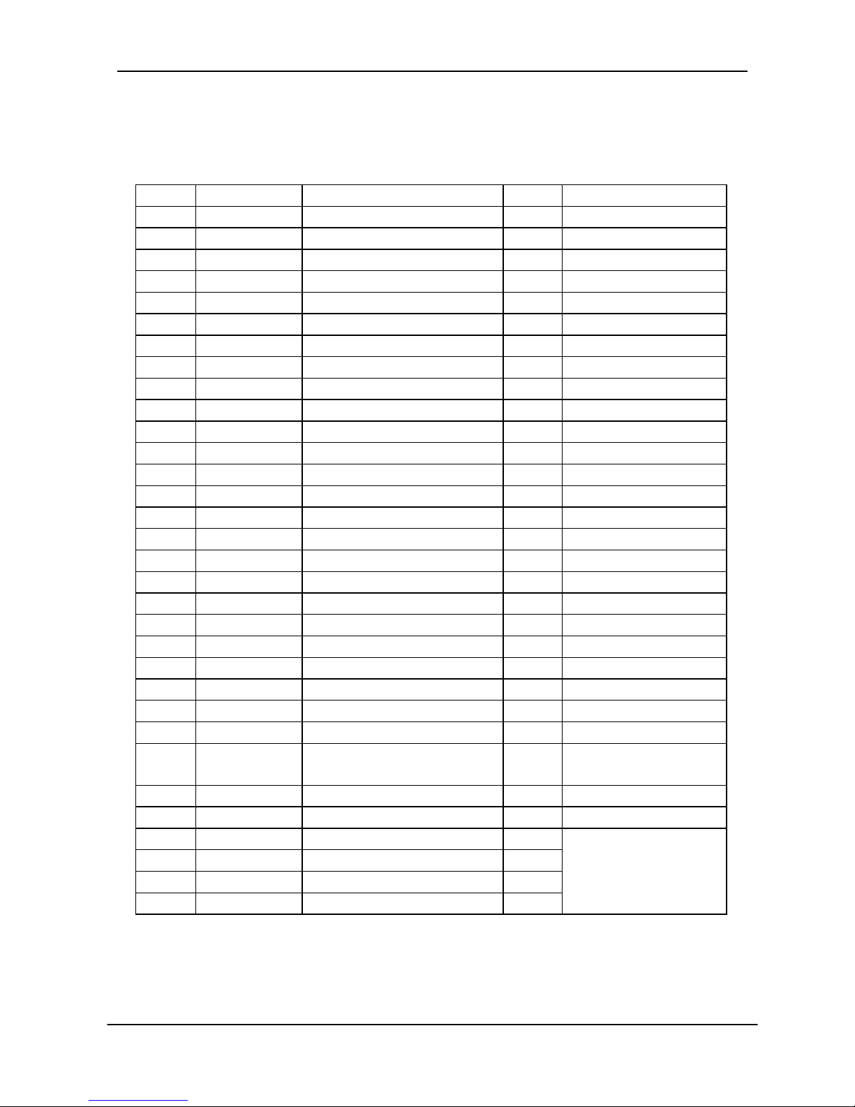
TCL Air Conditioner Service Manual
53
Outdoor Unit- TAC-24CSC/K
No. Part No. Part Na me Q’ty Remark
1 1084530501 Grille 1
Optional
2 1084530504 Top Cover 1
3 1210700102 Condenser 1
4 1084530510 Outdoor Motor Supporter 1
5 1170040063 Outdoor Motor 1
6 1070030017 Propeller Fan 1
7 1084530516 Left Plate 1
8 1084530514 Front Plate 1
9 1084530515 Fan Guard 1
10 1210700101 Capillary Assembly 1
11 --------------- Compressor and its Accessories 1
12 1210700102 Suction Pipe 1
13 1120700103 Discharge Pipe 1
14 1214561809 Base 1
15 1120120011 Two-way Valve 1
16 1084530502 Valve Supporter 1
17 1120130013 Three-way Valve 1
18 1084530503 Right Plate 1
19 1074530503 Electrical Box Cover 1
20 1084561802 Electrical Parts Box 1
21 1080010006 Capacitor Strip 1
22 1170100007 Compressor Capacitor 1
23 1170100030 Fan Motor Capacitor 1
24 1170200010 Terminal 1
25 1074060118 Cable Clamp 1
26 1174561803 Compressor Power Supply
Wiring
1
27 1173570502 Earthing Wiring 1
28 1174561801 AC Contactor 1
29 1190070003 Base Carton 1
30 1190070013 Cabinet Carton 1
31 1190070004 Cover Carton 1
Not shown in the Explosion
view.
Consist forfilterthe dry
Page 55

TCL Air Conditioner Service Manual
54
Outdoor Unit- TAC-24CHS/K
No. Part No. Part Na me Q’ty Remark
1 1084530501 Grille 1
Optional
2 1084530504 Top Cover 1
3 1210700202 Condenser 1
4 1084530510 Outdoor Motor Supporter 1
5 1170040063 Outdoor Motor 1
6 1070030017 Propeller Fan 1
7 1084530516 Left Plate 1
8 1084530514 Front Plate 1
9 1084530515 Fan Guard 1
10 1210700101 Capillary Assembly 1
11 --------------- Compressor and its Accessories 1
12 1210700201 4-way Vane assembly 1
13 1214561809 Base 1
14 1120120011 Two-way Valve 1
15 1084530502 Valve Supporter 1
16 1120130013 Three-way Valve 1
17 1084530503 Right Plate 1
18 1074530503 Electrical Box Cover 1
19 1084561802 Electrical Parts Box 1
20 1080010006 Capacitor Strip 1
21 1170100007 Compressor Capacitor 1
22 1170100030 Fan Motor Capacitor 1
23 1170200036 Terminal 1
24 1074060118 Cable Clamp 1
25 1174561803 Compressor Power Supply
Wiring
1
26 1173570502 Earthing Wiring 1
27 1174561801 AC Contactor 1
28 1174530303 Outdoor Pipe Sensor 1
29 1190070003 Base Carton 1
30 1190070013 Cabinet Carton 1
31 1190070004 Cover Carton 1
Not shown in the Explosion
view.
Page 56

TCL Air Conditioner Service Manual
55
Outdoor Unit- TAC-24CHSC/K
No. Part No. Part Na me Q’ty Remark
1 1084530501 Grille 1
Optional
2 1084530504 Top Cover 1
3 1210700202 Condenser 1
4 1084530510 Outdoor Motor Supporter 1
5 1170040063 Outdoor Motor 1
6 1070030017 Propeller Fan 1
7 1084530516 Left Plate 1
8 1084530514 Front Plate 1
9 1084530515 Fan Guard 1
10 1210700101 Capillary Assembly 1
11 --------------- Compressor and its Accessories 1
12 1210700201 4-way Vane assembly 1
13 1214561809 Base 1
14 1120120011 Two-way Valve 1
15 1084530502 Valve Supporter 1
16 1120130013 Three-way Valve 1
17 1084530503 Right Plate 1
18 1074530503 Electrical Box Cover 1
19 1084561802 Electrical Parts Box 1
20 1080010006 Capacitor Strip 1
21 1170100007 Compressor Capacitor 1
22 1170100030 Fan Motor Capacitor 1
23 1170200036 Terminal 1
24 1074060118 Cable Clamp 1
25 1174561803 Compressor Power Supply
Wiring
1
26 1173570502 Earthing Wiring 1
27 1174561801 AC Contactor 1
28 1174530303 Outdoor Pipe Sensor 1
29 1190070003 Base Carton 1
30 1190070013 Cabinet Carton 1
31 1190070004 Cover Carton 1
Not shown in the Explosion
view.
Consist the filter dryfor
Page 57

INDEX
1. Type of air conditioner
2. Four elements of air conditioning
3. Principle of refrigerating cycle
4. Definition of terms
5. The term of unit
6. The term of function
7. Mollier diagram
8. Psychrometric chart
9. Noise characteristics
10. Load calculation
11. The coordination coefficient of cooling capacity
ANNEX 2 GENERAL
TCL Air Conditioner Service Manual
Page 58

1. Type of air conditioner
1.1 Distribution according to function
Cooling
Cooling + Heating (Electric heater)
Cooling + Heating (Heat pump)
Window Window
Skinny
PTAC
Split Split
Floor Standing
Multi
Cassette
Duct
Convertible
27 c
20 c
40 c
Cooling
Cooling+Heating
19 c
Cassette
Split
Window
Floor Standing
Skinny
Convertible
PTAC
1.2 Distribution according to installation type
Duct
Multi
TCL Air Conditioner Service Manual
2
Page 59

2. Four elements of air conditioning
1) Temperature : The dry-bulb temperature by cooling or heating room air.
2) Humidity : A comfortable humidity condition of room air is generally kept by the relative humidity of
air, and the room air is controlled into a given relative humidity condition.
3) The degree of purity : Remove dusts in the air, and keep smoke from exceeding the allowable degree of
concentration.
4) Air flow : To disperse properly the air regulated in temperature, humidity and the degree of purity
into indoor, make an appropriate air flow and keep uniformly the temperature/humidity
condition of room unit.
• Standard for feeling comfortable
3. Principle of refrigerating cycle
3.1 Principle of refrigerating : It is as follows.
1) Sprinkling with water in summer causes to cool surroundings.
• Because water absorbs the heat of surroundings with evaporating.
2) Gasifying a liquid (R-22) which is easier to evaporate than water makes cooler.
• Because water evaporates at 100°C under 1 atmosphere but freon gas (R-22) does a very low temperature of
-40°C
3) It is an Airconditioner that the principle is used for.
Classification Summer Winter
Temperature 21 ~ 28°C 20 ~24°C
Relative humidity 30 ~ 60% 30 ~ 60%
Air flow 0.2m/s or less 0.2m/s or less
TCL Air Conditioner Service Manual
3
Page 60

3.2 Refrigerating cycle
1) Refrigerating cycle
2) The principle of refrigerating cycle
3) The role of each cycle
(1) Compression : The gasified refrigerant evaporated is absorbed into compressor through the suction pipe,
and then compressed by a piston in cylinder and turned into a gas of high temperature and
high pressure which is able to be liquified in a room temperature.
(2) Liquification : The gas of high temperature and high pressure in compressor is cooled by air in condenser
and liquified by a condensing heat.
(3) Expansion : With passing through the capillary tube, the high pressure refrigerant liquified in condenser
turns into a low pressure condition, which is easy to evaporate.
(4) Evaporation : The liquid refrigerant of low temperature and low pressure passed though the capillary tube
absorbs the room air heat in evaporator and evaporates into a gas.
MOTOR
COMPRESSOR
OIL
(LIQUID REFRIGERANT)
CAPILLARY TUBE
OUTSIDE COOLING
AIR FOR REFRIGERANT
PASS THROUGH
SUCTION LINE
COOL LOW PRESSURE VAPOR
COOLED
AIR
COMPLETE LIQUID
BOIL OFF POINT
LIQUID
PRESSURE
DROP
ROOM AIR HEAT LOAD
VAPOR INLET
HOT
DISCHARGED
AIR
LIQUID OUTLET
HIGH PRESSURE VAPOR
LIQUID REFRIGERANT
LOW PRESSURE VAPOR
ROOM AIR CONITIONER
EVAPORATOR COILS CONDENSER COILS
CYCLE OF REFRIGERATION
Compressor
(Mid. Temp)
(Hi. Temp)
Emission Absorbing
(Hi. Temp) (Low Temp)
(Mid. Temp)
Compression Liquification Expansion Evaporation
Low
Press
Gas
High
Press
Gas
High
Press
Liquid
Low
Press
Liquid
Low
Press
Gas
Condenser Capillary
Evaporator
TCL Air Conditioner Service Manual
4
Page 61

4. Definition of terms
1) Air conditioning : Keeping room air in an optimum condition, depending on the use or purpose. (Cooling, heat-
ing, humidity regulating, air cleaning, etc.)
2) Cooling (Heating) capacity : Calorie which is able to be released (or added) per a unit time in room.
It is expressed in Kcal/h, BTU/h or W.
3) Absolute humidity : The amount of vapor contained in the air. Generally it is equal to the amount of vapor by g
unit contained in 1m3air, and is expressed in g/m3.
4) Relative humidity : The ratio between the amount of vapor contained in the air and the maximum amount (the
amount of saturated vapor) of vapor capable of containing at that temperature in %.
* Relative humidity = Actual vapor pressure/Saturated vapor pressure x 100
or
= Actual vapor pressure of dew point temperature /saturated vapor pressure of dry-bulb
temp. x 100
5) Dew point temperature : The surface temperature which starts dewing on the surface when cooling a sub-
stance in the air.
6) Latent heat and sensible heat : Heat which causes a change in the state of a substance, with its temperature
constant, is called latent heat whereas heat which changes the temperature of
a substance is called sensible heat. Latent heat is expressed in terms of calories needed to cause a change of state of a substance per 1 kg. The following
equation shows that Q Kcal is needed to change state of a substance weight
G Kg when the latent heat is L Kcal/kg.
Q = GL
7) Thermal flow
(1) Radiation : A phenomenon which thermal energy as an electro-magnetic wave is transmitted
directly from a thermal source.
(2) Conductive emission : A phenomenon which transmits from high to low temperature when there is a
temperature difference partially in a substance.
(Example : When one tip of iron rod becomes hot.)
(3) Convection : When the temperature of a fluid like gas or liquid changes by heat, the high tem-
perature part expands and thus the density drops to cause to be light whereas
the low temperature part is to be heavy. It means a phenomenon that heat is
transmitted together when floating happens by the weight difference of air.
Liquid
Solid Gas
Sublimation Heat
Fusion Heat
Solidification
Heat
Condensation
Vaporization Heat
Heat
Three States of a Substance
TCL Air Conditioner Service Manual
5
Page 62

5. The term of unit
1) Kcal : Adding or releasing heat to or from a substance changes its temperature. This change of temperature is
in proportion the heat added or released. This heat is called calorie which is expressed in Kcal or cal.
1 Kcal is equal to the amount of heat required to raise the 1°C temperature of 1kg water 4°C.
2) BTU : 1 BTU is equal to the amount of heat required to raise the 1°F temperature of 1 lb water.
• 1 Kcal = 3.968 BTU, 1 BTU = 0.252 Kcal
3) RT : 1 RT (Refrigerating Ton) is equal to the capacity which makes 1 Ton water 0°C into ice 0°C in 24 hours. It
is expressed in calorie required to freeze water 1 Ton water 32°F(2000 lb) into ice 32°F, and when using
the solidification latent heat of water, 1RT is as follows
• 1 RT = 144BTU/lb x 2000 lb/24hr = 12,000 BTU/hr = 3,024 Kcal/hr = 3.517 KW
4) Hp : Horse Power
• 1 Hp = 0.75 KW = 645 Kcal/h, 1W = 0.86 Kcal/h
5) Temperature conversion (°C ↔ °F)
• °F = 9/5°C + 32, °C = 5/9 (°F-32)
6) Area or volume conversion
• 1m2= 10.764 ft2, 1m3= 35.3165 ft
3
7) Weight conversion
• 1Kg = 2.2 lb, 1 lb = 0.45 Kg
8) Unit conversion table
Classification BTU/h Kcal/h W KJ Hp RT
1BTU/h 1 0.252 0.293 1.055 0.00039 0.000083
1Kcal/h 3.968 1 1.163 4.186 0.00155 0.000329
1W 3.413 0.86 1 3.601 0.00133 0.000283
1KJ 0.948 0.239 0.278 1 0.00037 0.000079
1Hp 2559 645 750 2700 1 0.212
1RT 12000 3024 3516 12660 4.68 1
TCL Air Conditioner Service Manual
6
Page 63

6. The term of function
1) Compressor : Absorb and compress the low pressure refrigerant gasified in evaporator and flow into con-
denser. At this time, the low pressure needed is kept in evaporator and the refrigerant gas flows into condenser as high pressure condition. The most economical condition of compressor for an operating reason
is when the refrigerant gas absorbed into compressor is in dry-saturated condition. The overly-heated suction gas may cause the mechanical ability of compressor to be reduced and the cylinder clearance of compressor to be re-expanded, and as a result, the refrigerant may be used without its refrigerating effect.
The types of compressor is Recipro. type, Rotary type, Scroll type, Screw type, etc. and consists of cylinder, piston, vane, shaft, bearing, case and accumulator for structure reason.
2) Condenser : The high temperature/high pressure refrigerant gas compressed by compressor is sucked into
condenser and liquified by cooling. The condenser is cooled by the forced-convection of fan.
The calorie emitted from condenser is equal to the sum of the heat absorbed in evaporator and the calorie
used for compressor operating.
3) Evaporator : Absorb the heat from room air by forced-convection.
The liquid refrigerant in evaporator is evaporated by absorbing heat from room air and flowed into compressor as a gasified state. The evaporating temperature of refrigerant is decided by pressure, which is decided
by the wet-bulb temperature of suction air and the wind flow, and the pressure in evaporator is normally
5Kg/cm2G and the evaporating temperature is 5~8°C.
4) Capillary : Regulate the refrigerant flow into evaporator, lower the pressure of refrigerant, and expand into a liq-
uid of low temperature and low pressure. The type of capillary is generally a thin and long copper tube of
0.6~2.0mm2inner diameter and 1~2m long. The resistance of tube causes to turn into a liquid of low pressure and low temperature.
5) Dryer : Any moisture in refrigerating cycle may cause the compressor motor to be damaged or the refrigerant to
be an ice state in the middle of cycle, which blocks the flow of refrigerant. Dryer is installed in a cycle for the
purpose of removing such moisture.
There are two types of dryer ; a liquid line dryer which is connected serially to the condenser outlet and a
suction line dryer which is connected serially to the suction line, with a desiccative in dryer.
The dryer is designed for uni-directional flowing of the refrigerant.
6) Muffler : Since Recipro. type compressor discharges the compressed gas discontinuously, a pulsating sound or
vibration occurs through pipe. Muffler is installed in the discharged part of compressor for the purpose of
absorbing the vibration of the discontinuously-discharged gas.
7) Strainer : Strainer serves to remove foreign substances from refrigerant by a metal net pelt of fine grid or a
glass wool being inserted into metal vessel and refrigerant being passed through between the interval.
The mounted position is between condenser and temperature auto expansion valve.
8) Service valve : SVC valve is used for vacuum working and refrigerant filling. Front seat is called a state which
cap is opened and valve is completely rotated clockwise and refrigerant stops flowing in that condition,
whereas back seat is called a state which valve is rotated completely counter-clockwise and refrigerant
flows. In case of pressure measurements or vacuum work from service valve, the back seat condition is
changed into some front seat condition. Product is released in front seat condition, so the back seat by
brake-in is not needed.
TCL Air Conditioner Service Manual
7
Page 64

9) Motor : Drive a rotating force by electric power and supply the driving force to fan and blower in both indoor and
outdoor of air conditioner.
10) Fan : Serve to blow air through condenser and blow out the heat generated with refrigerant liquified in con-
denser. Its structure is similar with a motor fan.
11) Blower (Cross Flow Fan: C.F.F) : Suck room air, blow into evaporator, make evaporator absorb the heat, and
disperse the cooled air into room. Blower is placed indoor unit, so a small size, high wind flow and low
noise type is used.
12) Thermostat (Thermistor) : Sense the suction air into room and regulate automatically room temperature by
compressor on/off depending on temperature. Thermostat is used for a mechanical type model and thermistor for a micom type control method.
13) Capacitor : Supply a driving torque to the compressor motor or fan motor for aircon and make the operating
efficiency better during operation.
14) Over load protector (O.L.P) : A protective device of automatic return type which is placed in the wire of com-
pressor and shuts off the power of compressor motor against the overheat and overcurrent of compressor.
At this time, compressor is stopped operating by power off and fan only is at work. Generally the working
temperature is 115±5°C and the return temperature is 93±5°C.
15) High pressure switch (H.P.S/W) : A protective device of automatic return type which protects compressor
from overload by sensing the discharge pressure of compressor, working at an abnormal high temperature,
and shutting off the electric circuit. Generally the working pressure is 28kg/cm2G and the return pressure is
23 kg/cm2G.
16) Sump heater : A cord heater which is wound around the compressor bottom, and its type is decided depend-
ing on the capacity of compressor. If compressor is not at work at power on, sump heater is at work
whereas if compressor works, sump heater does not work, so be sure to always keep the compressor
temperature higher than any other unit.
17) Accumulator : A kind of liquid refrigerant separator which prevents the liquid refrigerant from sucking into
compressor and is installed in the suction inlet of compressor.
18) Reversing valve (4 way valve) : Convert the flow of refrigerant upon cooling/heating switch-over, electrically
power on when heating and off when cooling, be installed in outdoor, and have four connecting valves as
shown in the name. The refrigerant passing through compressor always flows to a constant direction and
is able to reverse-operate completely the refrigerating cycle of both cooling and heating by a reversing
valve. Consist of reversing valve and solenoid valve. The main valve in reversing valve uses a nylon resin
which is deformed by heat 120°C or over and thus causes valve not to work, so be cautious while
operating or when welding.
TCL Air Conditioner Service Manual
8
Page 65

19) Solenoid valve : Regulate the refrigerant flow by refrigerant on/off in cycle which refrigerant flows according
as the valve operates through a coil unit being powered on. Mainly it is used when reversing the 4 way
valve of a cooling/heating model or constructing each unit cycle of multi model.
20) Check valve : Prevent refrigerant from reverse flow in refrigerating cycle. It is installed in a place where it is
necessary to prevent the reverse flow of refrigerant in a copper pipe. It has a mechanical structure and
attached to the opposite of a heating capillary to expand the heating/cooling model by two speeds, and is
constructed so as to flow through capillary in heating and through the check valve in cooling only.
TCL Air Conditioner Service Manual
9
Page 66

7. Mollier diagram
7.1 Refrigerant state transition on Mollier diagram
1) Refrigerant changes iso-barically and iso-thermally in evaporator, so enthalpy (the heat absorbed from evapora-
tor) increases as shown in Figure 7.1 below.
2) In compressor, as the running speed of compressor is fast, it is thought there is no thermal input/output from or
to the outside within a short time, which is regarded as an adiabatic change. Accordingly the compression
process rises upto the discharge pressure along the iso-entropic line and the amount of energy of the
compressor is the same as the enthalpy change of refrigerant between compressor cylinder inlet and outlet.
3) In condenser, the overheated vapor is cooled as much as the
degree of overheat, saturated, and then condensed and
somewhat over-cooled. The process is established by an isobar
process, so an enthalpy down (the calorie emitted from
condenser) happens horizontally on diagram.
4) Expansion process is a throttle expansion which there is no
enthalpy change before and after the expansion valve and the
pressure and temperature drop, so the process changes
vertically downward.
7.2 How to draw a refrigerating cycle
For example, draw a refrigerating cycle under the following operating condition.
1) Evaporation & condensation temperature :
Find an evaporation temperature 8°C on the saturated
liquid line or saturated vapor line in Mollier diagram
and draw a horizontal line, isobar line (pressure 6.54
kg/cm2abs) from that point. In the same manner, draw
a isobar line at condensation temperature 46°C, and
the evaporation and condensation process changes
states between two isobar lines.
2) Suction gas state of compressor : The state of compressor suction gas is the same as that of refrigerant at
evaporator outlet, and the evaporation temperature and is 8°C and the degree of superheat is 8°C, so the
temperature of suction gas is to be 16°C Accordingly the state point of compressor suction gas is the
intersection between pressure 6.54 kg/cm2abs at wet vapor 8°C and superheat vapor 16°C, and is a point of
pressure 6.54 kg/cm2abs, temperature 16°C, enthalpy 152.0 Kcal/kg, non-volume 0.0024m3/kg, entropy 1.182
Kcal/kg °K. (See Figure 7.3)
P
i
Compression
Evaporation
Expansion
Condensation
Figure 7.1 Refrigerating cycle
Refrigerant R-22
Evaporation temp. 8°C
Condensation temp. 46°C
Overheat temp. of suction gas. 8°C
Temp. just before expansion valve. 40°C
P
46 C
8°C
tc = 46 C
46 C
8 C
tc = 8 C
=18.1kg/cm, abs
cm, abs
= 6.54kg/
2
2
d
P
s
P
i
P
8 °C
16 °C
tc = 16°C
Evaporation
Compression
A
16°C
152kcal/kg
8°C
s
P
i
Figure 7.2 Evaporation & condensation temperature
Figure 7.3 Suction gas state of compressor
TCL Air Conditioner Service Manual
10
Page 67

3) Discharged gas state (the state at compressor outlet or condenser inlet) : An adiabatic change is almost
seen in compressor, so the state of discharged gas follows the isentropic line at point B of Figure 7.4.
Accordingly the state point of discharge gas is the intersection with wet-vapor pressure 18.1 kg/cm2abs entrophy 1.138kcal/kg °K at condensation temperature 46°C, and is a point of pressure 18.1kg/cm2abs, temperature
75°C, enthalpy 158.0 Kcal/kg, specific volume 0.00152m3/kg, entropy 1.182 Kcal/kg °K, and superheat 30°C.
(Figure 7.4)
4) State of condensed liquid : The temperature of refrigerant liquid just before expansion valve in the design condition is 40°C, so the state point is the intersection between 46°C wet air pressure 18.1kg/cm2abs and 40°C
isothermic line (point C of Figure 7.5) in pressure 18.1kg/cm2 abs, temperature 40°C, enthalpy 112.0 Kcal/kg,
supercooling 6°C.
5) State of expansion valve outlet (The state of evaporator inlet) : The state is changed on isentropic line without thermal input/output in expansion valve, so the state point is the intersection between enthalpy 112.0
Kcal/kg line and evaporation temperature 8°C isothermal line (point D of Figure 7.6) at pressure 6.54kg/cm
2
abs, temperature 8°C, enthalpy 112.0 Kcal/kg, specific volume 1.0080m2/kg, entrophy 1.025 Kcal/kg °K, and the
degree of dryness 0.2.
P
P
td = 46°C
158.0kcal/kg
B
75 C
i
d
P
P
112kcal/kg
td = 46°C
C
i
40°C
46°C
40°C
d
Isenthalpy line
Supercooling=6°C
P
8°C tc=
112.0 kcal/kg
40°C
D
P
d
Ps
i
P
O
q1 = (ia
q3 = (ia-ig)
Evaporation
Evaporation temp.= 8°C
Condensation temp=46°C
Condensation
Suction gas temp. = -16°C
Dry saturated vapor
q2
46°C
40
-if)
c
a
de
f
g
b
Al
Compression
Expansion
Temperature
just before
expansion v/v
=40°C
Isenthalpy line
Figure 7.4 A state of discharge gas
Figure 7.5 A state of condensed liquid
Figure 7.6 A state of expansion valve outlet
Figure 7.7 A standard refrigerating cycle
TCL Air Conditioner Service Manual
11
Page 68

For the refrigerating cycle a➔b➔e➔f as shown in Figure 7.7, if the cooling capacity of condenser increases by the
temperature down of saturated liquid, cooling water or air and then the temperature of condenser outlet
refrigerant liquid decreases, the refrigerating cycle will be a➔b➔e➔f. Likewisely, the temperature difference when
the temperature of condenser outlet refrigerant liquid is below the temperature of saturated liquid at that pressure
is called the degree of supercooling, which enhances the refrigerating effect. The effect of supercooling is as
follows.
2) Work of compression : The heat equivalent of work which
has compressed refrigerant 1kg is the difference of enthalpy
between compressive process A➔B as shown in Figure 7.9,
and the equation of calculation is as follows.
Al = iB - iA ............................................................... (7.4)
3) Calorie of condensation : The calorie emitted from
condenser is the sum of the refrigerating effect and the heat
equivalent of work. (Figure 7.10)
qe' = qe + Al
qe = (iA - iD) + (iB - iA) = iB - iD.................................. (7.5)
7.3 Calculation of refrigerating cycle
1) Refrigerating effect : Calories which evaporator absorbes, and the refrigerant flowing through evaporator is a
wet vapor and at outlet a superheat vapor. In D➔A process in Figure 7.8, refrigerant absorbs Calorie qe from
surroundings with evaporating.
qe = iA - iD.......................................................................................................................................... (7.1)
The refrigerating effect is one which is calculated by equation (7.1), and is expressed in calories which
refrigerant 1kg absorbs from evaporator during A➔B➔C➔D cycle.
The refrigerating effect when the state of refrigerant gas sucked into compressor is changed into A', A'' in
Figure 7.8 is as follows.
qe' = iA' - iD......................................................................................................................................... (7.2)
qe" =iA" - iD ......................................................................................................................................... (7.3)
Standard Supercooling rise
Refrigerating effect
q
e=ia-ig <
q
e'=ia-if
Coefficient of performance <
q
e
=
ia-id
A
l ib-ia
q
e'
=
ia-if
A
l ib-ia
P
C
B
A
q"
A"
D
A'
e
i"Ai'Ai
A
q'
e
q
e
C
iDi i
P
C
B
A
AI
D
i
A
i
B
q
e
i
P
C
D
B
i
AiB
q
e
qe'= q
e
AI
A
AI
C
i
D
i
i
Figure 7.8 Refrigerating effect Figure 7.9 Work of compression
Figure 7.10 Calorie of condensation
TCL Air Conditioner Service Manual
12
Page 69

4) Circulation amount of refrigerant : An amount of refrigerant to be evaporated in evaporator to obtain the
refrigerating capacity needed. It is expressed in the weight by the unit time.
G: Circulation amount of refrigerant (kg/h)
Q: Refrigerating capacity needed (Kcal/h)
qe: Refrigerating effect by the refrigerant 1kg (Kcal/kg)
To decide the capacity of compressor, the circulation amount of refrigerant should be converted into the suction
gas amount of compressor.
V: Suction gas amount of compressor (m
3
/h)
VA: Specific volume of refrigerant at compressor inlet (m3/kg)
The amount of piston extrusion is calculated as follows.
D: Diameter of cylinder (m)
n: Rotational speed of compressor (rpm)
L: Piston stroke (m)
N: No. of cylinder
5) Coefficient of performance : The efficiency of refrigerating cycle. It is expressed in COP as the abbreviation
of Coefficient of Performance.
G =
Q
............................................................................................................................................. (7.6)
q
e
COP =
Refrigerating effect
¡
Refrigerating effect
Heat equivalent of work Shaft power for compressor(KW) x 860
COP =
qe
=
iA-iD
...................................................................................(7.9)
Al iB-iA
V = GvA=
Q
vA
=
QvA
(m3/h)
.......................................................................................................... (7.7)
qe iA - i
D
V' = πD2L X 60nL
............................................................................................................................................. (7.8)
4
Al : Heat equivalent of work for compression (Kcal/kg)
qe : Refrigerating effect (Kcal/kg)
COP is greater than 1, and the greater COP is, the better the performance is.
For the general COP of refrigerator, compressive efficiency hc and machine efficiency hm should be considered.
COP'= COP x hc x hm ............................................................................................................................(7.10)
TCL Air Conditioner Service Manual
13
Page 70

Example) By using the Mollier diagram of R-22, find the compression ratio, refrigeratiny effect, work of compres-
sion, calorie of condensation, circulation amount of refrigerant, coefficient of performance, and refriger-
ating effect per 1KW.
Condensation pressure : Pd = 18.1kg/cm2abs
Evaporation pressure : Ps = 6.5kg/cm2abs
Compression ratio : Pr = Pc/Pe = 18.1/6.5 = 2.78
Enthalpy : iA = 148.5kcal/kg
iB = 158.5kcal/kg
iC = 110kcal/kg
iD = 110kcal/kg
iC' = iD'= 112kcal/kg
iE = 148kcal/kg
Accordingly, Refrigerating effect : q1 = iA - iD = 148.5 - 110 = 38.5 [kcal/kg]
Work of compression : A1 = iB - iA = 158.5 - 148.5 = 10 [kcal/kg]
Calorie of condensation : q2 = iB - iC = 158.5 - 110 = 48.5 [kcal/kg]
Circulation amount of refrigerant : G=Q/q1 = 3320/38.5 = 86.2 [kg/h.RT] (per 1 Refrigerating Ton)
COP : q1/A1 = 38.5/10 = 3.85
Refrigerating effect per 1KW : k = 860 x 3.85 = 3311 [kcal/h. KW]
D
E
A
C
C'
B
D'
8°C
15.0
3.0
38°C
46°C
16°C
40°C
75°C
110 112 148 148.5 158.5
0.0016m /kg
3
0.0024m /kg
3
Absolute Pressure(kg/cm2 abs)
TCL Air Conditioner Service Manual
14
Page 71

Mollier diagram
p-h graph of R22
p-h graph of R22
S=1.35kcal/kg.K
v= 0.0015m
3
/kg
P (kgf/cm2)
150.0
150.0
70
80
90
100
110 120
130
140
150
160
170
180
190
60.0
40.0
20.0
10.0
6.0
4.0
2.0
1.0
0.6
0.4
0.2
0.1
0.06
0.04
0.02
t=-90°C
t=-90°C
-80
-70
-60
-50
-40
x=0.1
0.2
0.3
0.4
0.5
0.6
0.7
0.8
0.9
-30
-20
-10
0
10
20
30
40
50
60
70
80
t=90°C
t=90°C
50°C
50°C
50°C
100°C
150°C
200°C
0.002
100°C
150°C
200°C
1.30
1.25
1.20
0.003
0.004
0.005
0.006
0.008
0.01
0.06
0.1
0.15
0.2
0.4
1.0
0.02
0.03
0.04
1.15
0°C
80
-80
70
60
-60
-70
50
-50
40
-40
30
-30
20
-20
10
-10
0
100.0
60.0
40.0
20.0
10.0
6.0
4.0
2.0
1.0
0.6
0.4
0.2
0.1
0.06
0.04
0.02
70
80
90
100
110
120
130
h kcal/kg
140
150
160
170
180
190
s=1.10kcal/kg.K
150.0
v= 2.0m
3
/kg
TCL Air Conditioner Service Manual
15
Page 72

8. Psychrometric chart
8.1 Psychrometric chart
Psychrometric chart shows the characteristics of moist
air by a diagram, including i-x, t-x, and t-i diagram. The
i-x diagram is shown in the right side. A point expressing the state of air in the psychrometric chart is called
a state point, which is used for finding a dry-bulb temperature,wet-bulb temperature, dew point temperature,
relative humidity, absolute humidity, enthalpy, etc. For
example, at dry-bulb temperature 26°C, and relative
humidity 50%, the enthalpy, absolute humidity, wetbulb temperature, dew point temperature and specific
volume is found from the psychrometric chart as follows.
Enthalpy I = 12.6 (Kcal/kg)
Absolute humidity x = 0.0105 (kg/kg)
Wet-bulb temperature t’ = 18.71 (°C)
Dew point temperature t” = 14.70 (°C)
Specific volume v = 0.862 (m
3
/kg)
8.2 Discomfort index (DI)
In summer, Discomfort Index is frequently used in the weather forecast on TV or newspapers. Man feels hot
or dry according as the relative humidity is high or low, but not the absolute humidity. Generally, now that we
feel discomfortable at high relative humidity, the state which is felt uncomfortable at both dry-bulb and wetbulb temperature may be expressed empirically as an equation, Discomfort Index (DI), which is used as an
emotional index for summer temperature and humidity condition.
* DI = (Wet-bulb temperature + Dry-bulb temperature) x 0.72 + 40.6
* Degree of DI
Figure. Psychrometric chart
0.0105
V=0.862
t'=18.71
I=12.6
t"=14.70
=50%
26
[°C]
DI Degree of DI
86
80
75
70
68
Intolerable discomfort (Unable to bear the sultry weather.)
Everybody feels uncomfortable. (Sweat at hot weather.)
Half or more people feel uncomfortable. (Feel the heat a little.)
Start to feel uncomfortable.
Comfortable
TCL Air Conditioner Service Manual
16
Page 73

8.3 Dewing
The most damp condition of air is at the saturated air condition of relative humidity 100% which is unable to
contain moisture any longer. As a result, the water vapor (moisture) in the air is condensed and turned into
liquid as waterdrop which can be seen. Such phenomenon is called dewing or condensation, commonly
“sweating”.
Dew point temperature means the temperature of air when starting to form dew. For example, when taking
out a bottle of beer from refrigerator in summer, you have probably seen several times the surface of beer
bottle sweats, that is, waterdrop form. The phenomenon is because the moist air around the bottle of beer is
changed rapidly into a state beyond relative humidity 100% with rapid cooling below the dew point temperature, and the vapor in the air not contained forms dew. Maybe you have ever experienced damages that summer cooling in your house caused the bedclothes in wardrobe to be damp by de wing or the winter heating
caused to form dew on window and waterdrop to flow into wall or floor carpet.
❒ Dewing prevention
Such a fine particle (vapor in air) that its shadow or shape has never appeared is rapidly cooled when it
touches a cold substance below dew point temperature. That is, shocking or starting by rapid cooling
causes waterdrops to be emerged out; dewing.
It is necessary to prevent from dewing in room because it gives trouble. For example, in order to keep
room windows from dewing in heating, insulation effect should be increased by making room humidity
down or using a double window.
Americans frequently does not humidify when heating, and if humidifying, they lower room humidity considerably.
Relative humidity in room to prevent inner area from dewing
Heat loss rate
[Kcal/m2h°C]
Outdoor temperature [°C]
-10 -7.5 -5 -2.5 0 2.5 5
22[%] 25[%] 29[%] 33[%] 38[%] 43[%] 48[%]
29 32 36 40 45 50 55
37 41 44 48 53 58 62
48 52 55 59 62 66 70
62 65 67 70 73 76 79
79 80 82 83 85 87 89
6
5
4
3
2
1
TCL Air Conditioner Service Manual
17
Page 74

❒ Psychrometric chart
PSYCHROMETRIC CHART
NORMAL TEMPERATURES ATMOS PHERIC PRESSURE 760mm Hg
(-10~+50°C, ATMOS PHERIC PRESSURE 760mm Hg)
Heat inherent moisture ratio
¡ =dh/dx[kcal/kg]
Sensible Heat Factor
Enthalpy h [kcal/kg(DA)]
Specific volume v [m
3
/kg(DA)]
0.75 0.76 0.77 0.78 0.79 0.80 0.81 0.82 0.83 0.84 0.85 0.86 0.87 0.88 0.89 0.90 0.91
-10 -9 -8 -7 -6 -5 -4 -3 -2 -1 0 1 2 3 4 5 6 7 8 9 10 11 12 13 14 15 16 17 18 19 20 21 22 23 24 25 26 27 28 29 30 31 32 33 34 35 36 37 38 39 40 41 42 43 44 45 46 47 48 49 50
Relative humidity ø [%]
Saturated degree ø [%]
Wet Bulb temperature t' [°C]
Dry Bulb temperature t' [°C]
Ice water
Absolute humidity x [kg/kg(DA)]
40
35
30
Steam partial pressure Pw [mmHg]
25
20
15
10
5
1
0
0.000
0.001
0.002
0.003
0.92
0.93
0.94
0.95
0.96
0.004
0.005
0.006
0.007
0.008
0.009
0.010
0.011
0.012
0.013
0.014
0.015
0.016
0.017
0.019
0.020
0.021
0.022
0.023
0.024
0.025
0.026
0.027
0.028
0.029
0.030
0.031
0.032
0.033
0.034
0.035
0.036
0.037
0.018
1
0
-8
-6
-4
-2
-1
0
1
2
3
4
5
6
7
8
9
10
11
12
13
14
15
16
17
18
20
21
22
23
24
25
26
27
28
29
30
31
32
33
34
19
2
3
4
5
6
7
8
9
10
11
12
13
14
15
16
17
18
19
20
21
22
23
24
25
26
27
28
29
30
TCL Air Conditioner Service Manual
18
Page 75

9. Noise characteristics
9.1. Sound composition :
The physical amount of sound is expressed in a logarithm and the sound level (dB) is calculated by simple
addition or subtraction.
Lc, the sum of n sounds L1, L2, ....Ln (dB) is calculated by the following equation.
Lc = 10 log (10
L1
/10 + 10L2/10 + ..... 10Ln/10)
Generally, the noise level by composing two sounds of L1 (dB) and L2 (dB) is found in the following figure.
Example) When composing 60dB and 57dB sounds, the level of
complex sound is calculated as follows.
L1-L2=60-57=3
n the left figure, ∆L¡ 1.7
Complex sound level : L3 = L1+∆L
= 60+1.7=61.7dB
L3 = L1+10log(1+10
-(L1-L2)
/10)
= L1+∆L(L1≥L2)
The equation is applied to the sound decomposition method.
When complex sound (measured sound) is L3(dB) and
background noise is L2(dB), the object sound L1 (dB) is
calculated as follows.
L1= L3 + 10 log (1-10
-(L3-L2)
/10)
= L3 - ∆L'(L3 ≥ L2)
Example) While machine sound is measured 65dB, the noise at
machine stopping is 63dB.
Accordingly the noise level of machine itself is
L3-L2 = 65-63 = 2
In the right figure, ∆L' ¡ 4.33
Noise level of machine is
L1 = L3-∆L' = 65-4.33 ¡ 60.7
(Figure: Calculation chart of dB composition)
(Figure: Calculation chart of dB decomposition)
3.0
2.8
2.4
2.0
1.5
1.2
0.8
0.4
0 1 2 3 4 5 6 7 8 9 10 11 12 13 14 15
L
1 L2
(dB)
∆L
6.87
4.33
3.00
2.19
1.65
1.25
1
0
1
2
3
4
5
6
7
2 3 4 5 6 7 8 9 10
L3 L2
11 12
0.96
0.36
0.46
0.58
0.75
0.26
(dB)
∆L'
TCL Air Conditioner Service Manual
19
Page 76

9.2 Sound attenuation
The sound pressure level Lp[dB] at r[m]from a point sound source is composed of the following equation.
Lp = Lw + 10 log (Q/4πr2 + 4/R)
Lw : Power level of sound source
R : Real integer
Q : Directional factor (Spherical sound : 1, Semi-spherical sound: 2)
Generally the noise level Lpr (dB) at r[m] from the sound source is
Lpr = Lps - 20 log r + C
* Lps : Sound source level (dB)
C: Characteristics of sound sources including a point sound source and plane sound source
And the noise level Lp1 and Lp2 at r1 and r2 from noise source is
Lp1 = Lps-20 log r1 + C, Lp2 = Lps - 20 log r2 + C
Therefore, eliminate Lps, and Lp2 = Lp1 + 20 log r1/r2
Example) In a condition the four condensers of noise
level 50dB are placed parallelly, what is the
complex noise at point A? And what is the
sum of noise at background noise 35dB and
1m distance?
1) The noise level at point A of each aircon is ;
Lpa = Lpb = 50+20 log 1/2 = 44.0
Lpc = 50 + 20 log 1/3 = 40.5
Lpd = 50 + 20 log 1/4 = 38.0
2) Considering the noise source, the complex noise level is;
L =10 log(10
44
/10+1044/10+10
40.5/
10
+1038/10+1035/10)
= 48.5(dB)
9.3 Allowable level of noise
1) NC curve
NC curve as an abbreviation of Noise Criteria is a
curve expressing the allowable level by frequency for
noise evaluation.
For NC 50, the band level at octave frequency band
1200-2400Hz is at 50dB and the high level is allowed
at low sound side. To inhibit to NC50, the result of
octave band analysis at that sound should be below
NC50 curve.
2) Allowable level of noise
a
2m
2m
3m
Point A
4m
b
c d
90
80
70
60
50
40
30
20
10
20 75 150 300 600 1200 2400 4800
75 150 300 600 1200 2400 4800 10000
NC-20
NC-30
NC-40
NC-50
NC-70
NC-60
Octave frequency band level (dB)
(0 dB=0.00002 µ bar)
Octave frequency band level (c/s)
NC Curve
Studio 15-20 25
Music hall 20 30
Theater 20-25 35
Classroom 25 40
Conference room
25 40
Apartment, Hotel
25-30 40
House 25-30 40
Hospital 30 35
Library 30 40
Small office room
30-35 45
Large office room
45 50
Factory
50 60-70
dB(A)
dB(A)
Place
Place
NC
Curve
NC
Curve
TCL Air Conditioner Service Manual
20
Page 77

10. Load calculation
10.1 Cooling/Heating load calculation
1) Calorie from wall body
2) Calorie from glass
3) Calorie by clearance wind
4) Calorie generated from human body
5) Calorie generated from thermal instruments
6) Shaft heat load of wall body
7) Acquired calorie within machine
8) Others (Outdoor load)
The cooling load is calculated by summing up from item 1 through item 8. As a reference, the calorie
generated from human body is as follows.
Table 10.1 Calorie from human body (Kcal/h. person)
Note : SH : Sensible heat, LH : Latent heat
28(°C) 27(°C) 26(°C) 24(°C) 21(°C)
SH LH SH LH SH LH SH LH SH LH
44 44 49 39 53 35 58 30 65 23
45 56 49 52 53 48 61 40 69 32
45 68 50 63 54 59 62 51 72 41
45 81 50 76 55 71 64 62 73 53
48 91 56 83 62 77 71 68 81 58
48 141 56 133 62 127 74 115 92 97
56 159 62 153 69 146 82 133 101 114
68 184 76 176 83 169 96 156 116 136
113 252 117 248 121 244 132 233 153 212
Sit upright
Studying
Office work/light walking
Erect, sit upright, walk
Business
Seated work
Normal dancing
Walking 4.8 (km/h)
Balling
Theater
88
School
101
Hotel Dept.
113
Bank
126
Restaurant
139
Light work at factory
189
Dance hall
215
Heavy work at factory
252
Balling
365
Working posture
Room temp
Example Total
TCL Air Conditioner Service Manual
21
Page 78

Example) Calculation of simple cooling capacity
By using a simple cooling capacity calculation table, calculate the cooling load.
0.9
2.5
0.5
1
5
7
4
2.3
Double window
(Without pent roof)
(unit:m)
Entrance door
(Opening/shutting door)
Wall (inner wall)
Living room
Wall
No sunshine
North
Condition : .•
Apartment living room (middle layer)
• 4 persons in room
• 2 fluorescent light 20W
• One TV set 150W
Sunshine
Veranda
Sliding door
(Double window)
(Curtain)
TCL Air Conditioner Service Manual
22
Page 79

10.2 Simple cooling capacity calculation table
Item Area (m2) Coeff. Load(Kcal/h) Calculation method
1.Window
2.Outer
wall
3.Compart
ment
4.Ceiling
5.Floor
6.
Ventilation
7.Person
8.Heater
Total
Max.direc
tion of
sunshine
load
(Double
window:
Coeffi.x4)
Others
Sunshine
North,
Shade
Sliding
door, glass
Wall,
Open/close
door(APT
entrance)
Upper is room.
Upper is
roof.
Lower is
ground.
Lower is room
Korean-style
house
Western-style
house
Fluorescent
light
Electric
heaters
Gas
instruments
50
25
25
10
10
15
15
10
10
10
35
0
10
25
15
1
0.86
Sunshine
No
Sunshine
E
S
W
E
S
W
(1) Calculate each window load for one
direction only of maximum load.
(2) For all the other windows, calculate as
“Others” item.
(The sunshine window not max.load, the
east, west & south windows all day shade,
and north window are calculated as others.
(1) For outer wall area, subtract the window
area.
(2) All of each outer wall to the directions
(east,west,south) with sunshine is
calculated as “sunshine” and the outer
wall to north or shade direction is calculated as north and shade.
(1) For sliding doors and glass, calculate all
the movable part.
(2) Calculate wall except sliding door and
glass area.
(3) Do not calculate saparately wall and
sliding door.
(1) Use the area of ceiling.
(2) The upper part of the top floor or one
story building is roof.
(1) If the space beneath floor is ventilated
even though it is ground, calculate as
“room”.
(1) Be ventilated by a clearance wind or
door open/close. If using a fan, this calculation is not applicable.
(1) Calculate maximum number of persons
if possible, but follow customer’s
request.
(2) Unless otherwise specified, general
housing is based on one person per
floor area 3.3m
2
.
(1) For other electric appliances,
input (W) by coefficient. Fluorescent
light : coefficient 1. (2) Gas appliance is
calculated by gas heat * gas
consumption.
TCL Air Conditioner Service Manual
23
Page 80

10.3 Aircon selection
1) Calorie required per 1m
2
100 ~ 130 Kcal/h/m
2
2) Considerations in capacity selection
• A place of good insulation, an apartment ¡ 90~105 kcal/h/m
2
• A place of poor insulation, a slate building ¡ 135~150 kcal/h/m
2
• A place of poor insulation and many windows ¡ 150 kcal/h/m2or over
• A place of poor insulation, many windows, much sunshine ¡ 160 kcal/h/m2or over
• Western or southern room (+)
• Many persons in a room (+)
• Heater in a room (+)
3) Rough selection of capacity
Considering the above 2), add the clearance rate by 10% each except for lecture room, kitchen, or special
area, and select the capacity.
The nominal area is selected on the basis of outdoor 35°C and indoor 27°C, but actually the temperature in
condenser is higher than standard condition according to summer hottest temperature and condenser installation condition, so the capacity selection by the rough method does not matter.
TCL Air Conditioner Service Manual
24
Page 81

1900
1800
1700
1600
1500
1400
1300
1200
1100
1000
900
800
700
600
500
400
300
200
100
Daytime
Area to cooled-square feet
Cooling
Primarily
4000~
6000
4000 6000
5000
6000~
8500
24000~
27000
8500~
15000~19000
19000~24000 27000~32000
11000
11000~
15000
1900
1800
1700
1600
1500
1400
1300
1200
1100
1000
900
800
700
600
500
400
300
200
100
Band A - Occupied space above ceiling
Band B - lnsulated ceiling under attic
Band C - Non lnsulated ceiling under attic
Nighttime
Cooling
Cooling capacity required-BTU/Hr.
If area to be cooled includes a kitchen, add 1,000 BTU/Hr.
If more than two people occupy area, add 600 BTU/Hr. per person.
If only one person, subtract 600 BTU/HR.
How to read the cooling Selection Guide
1. Determine area to be cooled in sqare feet.
Locate that point on the left side of the Cooling Selection Guide.
2. Move horizontally across to Band A, B or C, according to ceiling condition in the area to be cooled as follows:
- Band A: Occupied space above ceiling
- Band B: Insulated ceiling under attic
- Band C: Non-insulated ceiling unter attic
This "band" on the Selection Guide indicates a range of BTU/Hr. capacity normally required to cool such an area.
11. The coordination coefficient of cooling capacity
You can use the cooling selection guide chart to determine the size unit best suited for the consumer's
application.
TCL Air Conditioner Service Manual
25
Page 82

ANNEX 3 TROUBLE SHOOTING
INDEX
1. Electric parts
2. Refrigerant system
3. Troubleshooting
4. Installation Fundamentals
TCL Air Conditioner Service Manual
Page 83

1. Electric parts
It is compressor and motor fan that finally drives after power is supplied. And it is necessary to check the internal factors like switches, protectors, or lead wires that are needed to reach the compressor and motor fan to
see if their connections are normal and the external factors to see if voltage is normally supplied.
1.1 External factors check
1) Working power and voltage drop
The rated voltage for airconditioner is specified in a workable range.
In order to operate airconditioner normally, it is desirable for the working voltage and minimum. starting voltage
to be within the following chart range.
Especially, just the fact that the voltage when airconditioner is not at work is within the working voltage range is
insufficient, and the voltage is sure to be within the working voltage range by measuring in a operating condition.
* Usable voltage = Product rating ±10%
2) Electric wire capacity
The electric wire for airconditioner should have an allowable current more than the load current of the circuit
and be able to control the voltage drop by the load current within 2%.
And it should be a thickness capable of keeping the voltage drop by a starting current within -10%, and especially for an airconditioner of single phase, the voltage drop (Flicker voltage) by the starting currnet be within
about 5%.
A = V1 - V2 : Voltage drop by the starting current of airconditioner (Flicker voltage)
B = V1 - V3 : Voltage drop by the normal running current of airconditioner
In case of using an airconditioner in a low voltage area where power supply voltage is low, especially, the Flicker
voltage due to inadequate wires may cause the fluorescent light to be off or may affect the other electric products.
So, care should be taken to the wiring work.
lnput voltage (V1)
Voltage drop
Voltage
Time
Starting voltage(V2)
Running voltage(V3)
V1 - V3
X 100 ≤ 2%(B case)
V1
V1 - V2
X 100 ≤ 5%(A case)
V1
TCL Air Conditioner Service Manual
2
Page 84

3) Wire thickness required
Rated current appliance(A) Nominal cross-sectional area(mm2)
Up to and including 6 0.75
Over 6 up to and including 10 1.0
Over 10 up to and including 16 1.5
Over 16 up to and including 25 2.5
Over 25 up to and including 32 4.0
Over 32 up to and including 40 6.0
Over 40 up to and including 63 10.0
For rated currents up to 3A, a nominal cross-sectional area of 0.5mm2is only allowed if the length of the cord
does not exceed 2m.
1.2 Internal factors check
1.2.1 Insulation resistance
Measure the insulation resistance between live part and dead metal part by 500V insulation resistor to
check if the insulation resistance is more than 10MΩ.
1.2.2 Insulation resistance measurement of compressor
Measure the insulation resistance of compressor between compressor terminal and dead metal part by insulation resistor, and the insulation resistance should be above 10MΩ.
Compressor may change the insulation resistance while running. Accordingly, measure the insulation
resistance just after running as needed.
• Note: For R-22 used in airconditioner, the dielectric rate on liquid state is high. If a contaminant is mixed
into R-22, the electric resistance is extremely low and the poor insulation is occurred. Accordingly,
be sure to prevent contaminants from mixing into refrigerant system.
Power
supply
• Operation switch
• Rotary switch
• Remocon
• Operation
indicator lamp
• Relay
• reversing coil
• Conductor
• Thermistor
• Pressure switch
• O.L.P
• Fuse
Switches Function parts Protector
Compressor
Motor Fan
TCL Air Conditioner Service Manual
3
Page 85

1.2.3 Running capacitor
1) Earth inspection between terminal and body
As shown in Figure 1, connect a resistor between one side terminal and body of condenser to check for
continuity.
2) Capacity inspection
(1) Remove the lead wire from both terminals of condenser to be checked.
(2) Contact both terminals of lead wire for 2-3 sec., and discharge.
(Be sure to perform to prevent the tester damage before measuring.)
(3) After discharging, contact both terminals of tester with the terminal of condenser to see the dial vibrating
direction of resistor. (See Figure 2.)
There are three kinds of dial vibrating direction in tester, and each vibrating direction and symptom is as
follows.
A: Normal : Dial shakes instantaneously and returns to the original state immediately.
B: Short : Dial remains moved.
C: Capacity consumed up : Dial does not move at all.
1.2.4 Motor fan
1) Power off, remove motor fan, and test independently.
2) Measure the resistance of main coil, sub coil and control coil in motor.
3) Use a good quality of capacitor in testing.
4) Diagnose the following troubles by the independent test, and replace motor.
a) Motor is not started.
b) Motor rotation rises very slowly.
c) Bearing failure : The shaft does not move.
d) Arc occurs in the motor inside.
e) Smoke emits from motor inside.
f) Excessive noise
Figure 1. Figure 2.
TCL Air Conditioner Service Manual
4
Page 86

Measuring main coil resistance : White ↔ Black
Measuring sub coil resistance : Brown ↔ Black
Measuring control coil resistance : Red ↔ Black
1.2.5 Thermostat
There are 3 kinds of thermostat malfunction.
1) Leak of gas charged in sensor part
2) Short of contact point
3) Wrong wiring
Switch off at room temperature 18-30°C, turn carefully the knob of thermostat from 1 to 10 (the number may
be different or a figure be used according to model) or reversely, and click sounds.
After the sound is heard, turn reversely to check again the click sounds.
If click sounds, the thermostat is in normal. If room temperature exceeds 30°C, test should be done after
cooling by putting the sensor part of thermostat into a cold water container because the contact point is not
opened.
If knob is turned but click does not sound, remove the thermostat cover and examine the contact point.
The fused contact point should be replaced with a new thermostat.
If contact point is not closed despite of the sensor temperature being sufficiently high, the gas at the sensor
part may be leaked. In this case, replace the thermostat.
When replacing thermostat, be sure to conduct after performing carefully as the above content.
1.2.6 Thermistor
Pull out the lead wire of thermistor terminal to test continuity.
Connect a tester to the terminal of thermistor and measure the resistance. The resistance value varies
according to the measuring condition and temperature, so in order to vary temperature forcibly, put water in
a cup, cool the sensor part of thermistor, and then measure the resistance, and also measure in a condition
that the sensor part of thermistor becomes warm by hands.
MC
S
O.L.P
Black
Red
Brown
White
TCL Air Conditioner Service Manual
5
Page 87

1.3 Compressor trouble diagnosis
1.3.1 Electrical troubles
1) Ground test
Test single phase and three phase in the same
manner.
(1) Shut off the power supply to product.
(2) Remove the wires connected to the compres-
sor terminal.
(3) Clean the compressor terminal and discharge
(suction) pipe.
(4) Measure the resistance of discharge (suction)
pipe and each terminal by using a R x 1K
scale of Ohm meter.
(5) If dial moves remarkably, the terminal is in
ground state. So, replace the compressor.
2) Wrong wiring check of compressor terminal
Examine the wiring diagram of compressor terminal or the electric circuit diagram of product on the cover
of compressor terminal to check if there is wrong wiring.
3) Checking of wire disconnection or overload protector (O.L.P) operating condition
This check is to see the wire terminal condition of motor inside, and for a single phase compressor with
O.L.P built-in, it identifies the O.L.P operating condition and wire disconnection.
(1) Shut off the power supply to product.
(2) Remove the wires connected to the compres-
sor terminal.
(3) After checking the ground state, cool the
compressor sufficiently.
(at room temperature)
<For single-phase compressor>
(4) Measure the resistance of each terminal by
Ohm meter R x 1K scale, and if dial does not
move, compressor is in opened condition.
<For three-phase compressor>
(5) Measure the resistance of each terminal by
Ohm meter R x 1K scale, and if dial does not
move, the wire between two terminals is
disconnected.
-> Action: Replace the compressor.
* OLP may be operated by the following causes, so be sure to find and remove the cause.
(1) Operation at low voltage
(2) Defects of operation or starting device
(3) Overheat of compressor motor due to the condensing coil closing, condensing motor defects,
liquid line close, or injection capillary close.
Ohm Meter
R x 1K
TCL Air Conditioner Service Manual
6
Page 88

1.3.2 Mechanical troubles
1) Not starting
(1) Phenomenon : Compressor is not started but the starting current continues to flow.
(2) Checking
a) Check capacitor. (for a type where a capacitor for compressor starting or operating is used)
b) If there is no trouble, it is judged as lock due to the wear of compressor inside or the damage of lubricating
device. Replace the compressor.
2) Poor compression
(1) Phenomenon : Compressor is at work, but the cooling capacity is weak, the pressure of high pressure side
is low and the pressure of low pressure side is high.
(2) Cause : Damage of valve in compressor inside, damage of connecting rod or crank shaft, or other internal
leak
(3) Checking
a) Stop and then start the condenser fan, and if the pressure of high pressure side does not increase, the
compressor is bad.
b) Measure the temperature of discharge pipe in compressor, and if it is abnormally low temperature (50°C or
less), the compressor is bad.
c) Conduct the pump down test of system to check the compression capacity.
- Power off the product.
- Close the service valve of liquid line. (Rotate the valve rod clockwise to close the valve rod.)
- Start product and observe the suction pressure.
- If compressor is normal by pumping down the system, pressure is kept 0-5 psiG (0-0.35kg/cm
2
.G), and if
the suction pressure increases, the compressor is bad due to the internal leak or valve damage.
(4) The compressor to be assumed as bad compression should be replaced.
If running for a long time in a bad compression condition, abnormal superheat may occur and the
compressor motor is burnt.
- Clean the cycle.
3) Overcurrent flowing while running
Check the working pressure, and if there is no trouble, it is assumed as the compressor bearing damage.
Replace the compressor.
(Excessive refrigerant charging may cause the overcurrent.)
TCL Air Conditioner Service Manual
7
Page 89

2. Refrigerant system
2.1 Refrigerant system troubleshooting
Check the following items when troubleshooting the refrigerant system.
1) The thermostat setting or remocon temperature setting is not wrong?
2) Air filter is not cleaned?
3) Blower fan control switch is not at "low"?
4) Ventilation lever is not opened?
5) There is no obstacle in suction or discharge side of outdoor unit?
6) Dirty heat exchanger causes the heat exchanging efficiency to be down?
(Thorough cleaning)
7) Cooling/heating load is not increased?
8) Too many persons are in room? (Cooling)
9) The insulation of window gap is not wrong?
If there is no trouble from the above checks and also if there is no trouble on the electric appliances of
airconditioner body, it is assumed as refrigerant system failure.
a) Set aircon to High cool, run cooling for 15 min. or more, and measure the temperature difference of suc-
tion/discharge air in indoor unit. (Adjust the wind direction so that wind is discharged to the front direction in
the installed condition.)
b) Measure the voltage and current in running condition.
c) Measure the pressure of low pressure side in cooling condition.
(If the temperature is low, convert into the test switch.)
2.1.1 Temperature difference and current of suction/discharge air in evaporator
Temperature difference
of suction/discharge air
No temperature difference.
80% or less of rated current.
Temperature diff.: Under 8°C.
80% or less of rated current.
Temperature diff.: Under 8°C.
Rated current or over.
Temperature diff.: 8°C or over.
Gas leak (almost) Refrigerant
cycle closed
Gas leak, refrigerant cycle
closed, bad compressor
Excessive refrigerant charging
No refrigerant cycle trouble
--
--
--
--
Running current
measurement
• Temperature difference of suction-discharge air
Normally, the temperature difference is based at 10°C. Actually, the judgemnt criteria is 8°C, because when the
room humidity is high, the temperature difference is small and when humidity is low, it becomes large.
TCL Air Conditioner Service Manual
8
Page 90

2.1.2 Pressure and temperature of refrigerant
The pressure in normal condition shows the figure in the right side
table, but the pressure (P1) of high pressure side tube is affected
greatly by the temperature change and about 16kg/cm2.G in a low
temperature condition (indoor/outdoor 21°C).
The pressure fluctuation is affected by the tube length or insulation
as well as temperature change, so measure the pressure (P2) of low
pressure side for the trouble shooting of refrigerant system.
<Trouble finding by pressure/temperature>
Note) The high/low temperature is a figure converted into pressure.
The low pressure is normally 4.5-6.0kg/cm
2
G.
(Temperature is normally 3°C-10°C.)
Indoor Side
Outdoor Side
Evaporator
Compressor
Capillary Tube
High pressure (Liquid side)tube
Low pressure(Gas side) tube
Accumulator
Compressor
P1
P2
Measuring place Pressure(kg/cm2G)
P1 About19.5
P2 About 5.0
Pressure Temperature
Cause Explanation
(than normal) (than normal)
Higher
Higher
Bad compression:
Compressor failure, Bad reversing Valve
Current flows weakly.
Cooling load is small. Current flows weakly.
Liquid refrigerant suction:
Excessive refrigerant charging
Gas short : Gas leak
Closed : Pipe internal
Current is low.
Current is low.
High pressure is not
increased rapidly in early
running stage.
Higher
Normal
Lower
TCL Air Conditioner Service Manual
9
Page 91

• Pressure measurement of low pressure side
As shown in Figure above, connect the manifold gauge to the low pressure (gas side) tube of condenser and measure the pressure.
2.1.3 Symptoms and actions
1) Short of refrigerant
The short of refrigerant appears in a slightly different symptom as (1) no refrigerant or (2) short of refrigerant.
(1) Symptoms : The temperature difference of suction-discharge air is 8°C or less, the running
current is less than the rated current, and the pressure of low pressure side is
low. (These are symtoms changed by short of refrigerant.)
(2) Judgement method : Frost is formed from the capillary tube outlet to the evaporator inlet.
The suction pipe of compressor is not cold. (The temperature of suction pipe is
similar to the outdoor temperature.)
The pressure of low pressure side in cooling is 4kg/cm
2
.G or less. (Surrounding
temperature : 30°C or over)
Refrigerant oil comes out from the evaporator-condenser connections and each
welded portion. (Finding the gas leak place)
(3) Actions: ➀ Find the gas leak area. (Check at balance pressure of 5kg/cm2.G or over.)
➁ Charge refrigerant to the specified level.
➂ Check for gas leak.
2) Closing of refrigerant system
(1) Symptoms : If the refrigerant system of strainer or capillary tube is closed, pressure drops at
the outlet of closed area, and refrigerant evaporates to form and attach dew or
frost.
The running current is less than the rated current, and the pressure of low pressure side is lower than the normal. If completely closed, the pressure of low
pressure side is to be 0kg/cm
2
.G as time goes by.
(2) Judgement method : The same symptoms as the short of refrigerant appears, and the same phenome-
non occurs even if refrigerant is sealed.
It takes 3 min. or more for refrigerant to balance.
If running in the condition, the temperature of discharge gas becomes higher, the
refrigerant oil is deteriorated, and the life time may be affected.
(Compressor motor may be burnt.)
Closed Closed
TCL Air Conditioner Service Manual
10
Page 92

Low
High
Gas side tube
Liquid side tube
Indoor
Unit
Outdoor
Unit
Compressor
3) Overcharge
(1) Symptoms : • The temperature difference of suction-discharge air is 8°C or less, the running current
is higher than the specified current, the pressure of low pressure side is high, and
the compressor and suction pipe are cold.
If running in the condition, pressure switch activates at overload operation to make
continuous operation impossible, compressor is difficult to start, and fuse or breaker is
easy to be disconnected.
(2) Actions : ➀ Dischage the refrigerant. (By 3-5kg/cm2G)
➁ Charge refrigerant to the specified level.
➂ Check for gas leak.
4) Bad compression
(1) Symptoms : • The temperature difference of suction-discharge air is little, the running current is less
than the specified current, the pressure of high pressure side is low, and the pressure
of low pressure is high.
(2)
Judgement method
:• Close service valve of high pressure side in condenser (front seat) and connect the
manifold gauge to the service valve of low pressure side.
(Close the valve.)
• If the dial of pressure gauge does not indicate 0kg/cm2G or less by cooling in the condition, the compressor is judged as bad.
Note) If pressure gauge is near 0kg/cm
2
G, immediately stop the cooling.
Otherwise, air flows into the refrigerating cycle or the compressor motor coating is taken off to cause the
poor insulation. So, care should be taken.
TCL Air Conditioner Service Manual
11
Page 93

2.1.4 Summary of check items by cause
Check item
Suction/discharge air
temp.diff. of evaporator
Short of refrigerant ¢ ¢ ¢ ¢ ¢ ¢ ¢ ¢
Capillary closing (a part) ¢ ¢ ¢ ¢ ¢ ¢ ¢ ¢
¢ ¢ ¢ ¢ ¢ ¢ ¢ ¢
¢ ¢ ¢ ¢ ¢ ¢ ¢ ¢
Bad compressor ¢ ¢ ¢ ¢ ¢ ¢ ¢ ¢
Rated current
Cooling Heating
Cooling 8°C Heating 14°C
Cooling Heating Cooling Heating
Low pressure
High pressure
Cause
Outdoor heat exchanger
contaminated
Indoor heat exchanger
contaminated
2.2 Precautions on repair
1) When discharging refrigerant (from pipe or body), the discharge outlet should direct the direction where
nobody exists.
2) Do not work near fire or flame.
3) Work in a large space if possible and arrange the scaffold.
4) Especially for working on rooftop, prepare a place to keep tools and take care to prevent from falling.
5) While running (pump down work, test run), do not insert hands into fan.
6) Clean the Indoor-outdoor connecting pipes and the manifold gauge edges to be free from dust or moisture.
7) Be sure to fill refrigerant to the specified level. (If refrigerant is too much or short, the capacity is down and
trouble may occur.)
8) Keep tools well, and check the measuring machine periodically.
TCL Air Conditioner Service Manual
12
Page 94

3. Troubleshooting
3.1 Product does not operate at all.
Power supply voltage check
Power input voltage
Driving load terminal
Display PCB connector
Power receptable voltage
Product input voltage
Evaportor-condenser
connecting pipe
PCB assy
(fuse, varistor, pattern)
AC about 14±3V
(General model)
Connector contact check
Power trans output voltage
PCB assy check
TCL Air Conditioner Service Manual
13
Page 95

3.2 Room fan does not operate at all.
Connector contact check
Motor bearing inserted
state
Fan(Blower) fixed state
Fan(Blower)
contact state
Motor output connector
Motor capacitor
Communication effor
Blower lock sensing
In dehumidifying, heating,
or artificial intelligence
operation, room fan may
be off.
Coil resistance (TP)
Motor capacitor
Motor insulation resistance
Motor-related parts check
Motor detail check
Error code check
PCB ass'y check
Operation mode check
Motor driving circuit
Relay output
TCL Air Conditioner Service Manual
14
Page 96

3.3 Compressor or outdoor fan does not operate at all.
Re-input after power off
Insulation resistance
Coil resistance
Capacitor capacity
Compressor OLP
Set the desired temperature of remocon to be lower by 2°C or over than room
temperature, and start the cooling operation.
Does not operate at all.
Temperature sensor
open/close check
Connector check
(Contact & power)
Disconnection/short circuit
check of connecting wire
Electric wire connection
check for outdoor side
Compressor & motor detail
check
Repeat running/stopping at
a short time period.
Thermistor and evaporator
surface contact check.
- Clearance is needed (5mm).
Connector check
(Contact & power)
OLP/High pressure switch/
Low pressure switch check
Operation mode
(dehumidifying) check
PCB assy check
Temperature sensing circuit
Relay output
TCL Air Conditioner Service Manual
15
Page 97

3.4 Up/down vane does not operate at all.
Vane bending, structures
interferance check
If a constant torque is felt when rotating vane by hands,
the assembled condition is normal.
At the moment the blower is stopped, up/down vane auto
switch is stopped, and if blower is started, auto switch is
re-operated.
- Especially, it occurs while dehumidifying or heating.
Motor shaft assembly check
Connector check
(Disconnection/short
circuit/malconnection)
Blower operating condition
check
PCB ass'y check
Step motor driving circuit
TCL Air Conditioner Service Manual
16
Page 98

3.5 Left/right louver does not operate at all.
Louver/link/cam assembly
check
If a constant torque is felt when rotating louver by hands,
the assembled condition is normal.
At the moment the room fan is stopped, louver auto
swing is stopped, and if room fan is started, auto swing is
re-operated.
- Especially, it occurs while dehumidifying or heating.
Motor shaft assembly check
Connector check
(Disconnection/short
circuit/malconnection)
Blower operating condition
check
PCB ass'y check
Step motor driving circuit
Synchronous motor driving circuit
TCL Air Conditioner Service Manual
17
Page 99

3.6 Function setting by remocon is disable.
Power input after power off
• UCheck the transmission signal of remocon
- Liquid crystal remocon: signal blinked
- Button remocon: LED blinked
• UCheck the product receiving
- Buzzer sounds.
- If there is no remocon transmission signal,
check the battery or remocon operation.
- If product receiving is not checked,
check the display PCB.
- In cooling mode, if compressor is stopped, blower is operated at low fan.
- In dehumidifying mode, to enhance the dehumidifying effect, blower is operated at low fan.
- In heating mode, blower is stopped or operated at low fan according to the situations
(defrosting, hot start, compressor off).
- In Sleep operation mode, blower is operated without switched-over (low or middle fan).
- In artificial intelligence mode, room fan switching-over is not possible by remocon.
Operation ON by remocon
Switchover the air flow by remocon.
PCB ass'y check
Display PCB assy check
- Connector/damage
TCL Air Conditioner Service Manual
18
Page 100

3.7 Cooling/heating conversion is disable.
Heating operation ON by remocon
4-way valve connection check
outdoor unit connecting wire
check
Switchover into cooling operation by remocon,
and after about 30 sec., check the 4-way valve
relay output = 4-way valve OFF
If 4-way valve is OFF, the refrigerant flowing sounds
(pee....) due to cycle switchover occurs.
If the reversing valve (4-way valve) is ON, "tick" sounds.
Connector check
PCB ass'y check
4-way valve coil resistance check
4-way valve relay output = ON
TCL Air Conditioner Service Manual
19
 Loading...