

Page 1

Alignment Procedure
1. GENERAL
1.1 Common Information
1.1.1 Use isolating transformer with low internal resistance.
1.1.2 Mains voltage is 90-260
1.1.3 All voltages and waveforms mentioned are with respect to Ground. Do not use
heat-sink as Ground.
1.2 How to enter factory Mode (Service menu, service mode)
1.2.1 Certain alignment procedures need to enter Factory Mode (Service Menu). There
are two ways to access factory mode:
One is :
A. Press and hold the VOLUME DOWN key tightly on the unit until minimum level
B. Don’t release the VOLUME DOWN key on the unit
C. Then press the CAPS key in 3 times on the RC
The other is:
Press “D-mode
shortcut key if “bit-0” of “mode 1” is at “0”.)
1.2.2 All system data in Factory Mode of “Key 8 & Key 9”
otherwise, the set will work abnormally.
1.2.3 It is suggested to disable the D-Mode key before the set leave the factory.
Navigation:
- Press “Pro+” “Pro -”
- Press “Vol+ ” “Vol-”
- Press “0” “1” “2” “3” “4” “5” “6” “7” “8” “9”
to access factory menu.; All change in factory data will be saved in EEPROM
automatically
- Press “BUS OPEN”
other ICs. This is only valid during automatic adjustment of white balance.
“ Key on the factory RC. (Please noted the “D-mode” key is the invalid
V AC, unless otherwise stated.
are not adjustable when servicing,
key to select option;
key to adjust or select option.
on the RC as the shortcut key
key on factory RC to cut off the I2C control from the CPU to
1.3 A few special modes:
1.3.1 Aging Mode is used before set alignment. It would operate in factory mode;
1.3.2 Vertical Stop mode
factory mode and repress “ mute” key to exit.
1.3.3 White balance alignment mode
1.3.4 Factory Mode (Initialization)
In factory mode, press RECALL button to initialize the FACTORY-OUT status.
is used to confirm the accelerating voltage. Press “Mute” key in
Volume: 30, PG password:0000, Favorite channel: ch1/ch2/ch3,
channel lock: disable, Picture mode: normal,
Color temp: normal, calendar:01-08-2004
2. Alignment procedure:
2.1 B+ voltage adjustment
2.1.1 Apply 110-240V AC (+5V) to mains power input, and Philips standard testing pattern
to RF input.
2.1.2 Adjust VR801 in STANDARD mode until voltage at TP2(B+) is 107V+
0.5V.
Page 2

Alignment Procedure
2.2 RF AGC adjustment
2.2.1 Input 58dB grey scale signal.
2.2.2 Press key “4” to enter RF AGC adjustment.
2.2.3 Press “OK” key to auto adjust RF AGC, also can adjust “RF AGC” key until the
letter change from “INACTIVE” to ”ACTIVE”.
* The others use default value.
2.3 Crystal oscillator frequency adjustment
2.3.1 Crystal oscillator frequency adjustment with NICAM
a. Input audio signal with NICAM.
b. Enter factory mode, press “game” key , then press “V+” key to adjust “DCXO
Auto”, until it displays “OKEY”.
2.3.2 Crystal oscillator frequency adjustment without NICAM
a. Input PAL color bar signal.
b. On factory mode, press “0” to adjust “DCXO Auto” until it steady at 128.
2.4 Screen & Focus voltage adjustment
2.4.1 Screen voltage adjustment
a. Input any signal.
b. Press “MUTE” key on the remote control and the screen will become a
horizontal line, here horizon stop vibration. Then adjust the “screen” VR on
the flyback until the horizontal line can just be seen (minimum visible
intensity).
2.4.2 Focus voltage adjustment
a. Input cross hatch pattern signal.
b. Adjust the “focus” VR on the flyback until the screen becomes clear.
2.5 White balance adjustment (NORMAL)
2.5.1 Choose Black and White pattern signal (PAL).
2.5.2 On factory mode, press “1” key enter white balance adjustment.
2.5.3 Measure the dark side of the picture with a color analyzer adjust RED and GRN
until the data on the analyzer become x=274+
2.5.4 Measure the bright side of the picture. Then adjust WPR, WPG and WPB until
the data on the analyzer become x=274+
2.5.5 Repeat step 1 and 2 until you get right color on both dark and bright side of the
screen.
Remark :
1. When adjusting, RED、GRN are used to adjust black balance and WPR、
WPB、WPG are used to adjust white balance .
2. On product line, the item which can be auto adjusted by auto test
equipment , its data according to auto adjust value.
3. White balance address please meet the fourth part in page 12.
8, y=280+8.
8, y=280+8.
2.6 Adjustment of Sub-brightness
2.6.1 Input grey scale + color bar signal.
2.6.2 Press key “6” enter sub-brightness adjustment.
2.6.3 At standard state, adjust “BRTC” parameter , until the secondary grey just be
seen.
* Do not change value “BRTS”.
Page 3

Alignment Procedure
2.7Picture geometric adjustment
2.7.1 Vertical geometric adjustment
a. Input a PAL cross hatch pattern signal .
b. Press key “2” enter Vertical geometric adjustment .
c. Use remote control to adjust one by one , watch the figure, until the center or the
corner grid has the same size .
d. When adjust vertical position , make the center of vertical intermediately.
e. In “5VSL”, the second half may blanking , adjust the first half at display range.
Remark: :
1 5VSC , 31 is fixed, don’t adjust .
2 5VPOS for vertical position.
3 5VAM for vertical amplitude.
4 5VSL for vertical slope.
5 5VL for vertical linearity.
6 5SCL for vertical S-correction.
7 5WBR for vertical start of blanking time on 4:3 mode (16:9 tube).
8 5WBF for vertical end of blanking time on 4:3 mode (16:9 tube).
9 5BSWBR for right side black width of blue screen .
10 5BSWBF for left side black width of blue screen.
* 5WBF/5WBR only use on matching 16:9 tube, at 4:3 picture mode, adjust
blanking time of R and F. First press “ZOOM” key switch to 4:3 mode, then adjust
5WBF and 5WBR respective to make the overscan meet the requirements.
*Adjustment is disabled when match 4:3 tube.
* 5BSWBR and 5BSWBF needn’t adjustment.
2.7.2 Horizontal geometry adjustment
a. Input a PAL cross hatch pattern with black and white background signal.
b. Press key “3” enter Horizontal geometric adjustment.
c. Use remote control to adjust one by o ne , watch the figure, until the center a nd the
vertical line at left and right side of the picture become straight.
Remark :
1. Adjust 5HSH for horizontal position, data should make H center mediacy .
2. 5PAR for parallelogram adjustment.
3. 5BOW for bow adjustment.
4. Adjust 5EWW for horizontal width.
5. 5EWP for pincushion correction.
6. 5UCR for upper corner correction.
7. 5LCR for low corner correction.
8. 5EWT for trapezia correction.
2.8 EHT/HEW ratio test:(test with PC program)
Equipment requirements : High Voltage Meter (Range: 0 - 40kV)、High voltage test
stick (1000:1)、Adjustable DC power supply、Dummy deflexion coil(as same
inductance as CRT which use to product).
Test method :
a. Mount the EHT cap on to the fixture and connect the EHT meter. Plug in the
dummy deflection coil. Connect the DC meter across C431.
b. Switch on the chassis and measure the ratio of EHT/HEW at I
= 0 ( brightness、
b
Page 4
Alignment Procedure
d. Apply PC program, V/V1 need satisfy request below :
2127P3 44-210FLN-SZ1A
contrast are minimum).
Here, the HEW is the DC voltage across C431.
EHT voltage V, HEW voltage V1.
EHT/HEW (V/V1)
A51KQK99X01
2.9 X rays over voltage protecting circuit test
Test method :
When TV ON with color bar signal, add more than 27V DV to C431, machine could
enter into protection mode, otherwise please inspect X rays over voltage protecting
circuit .
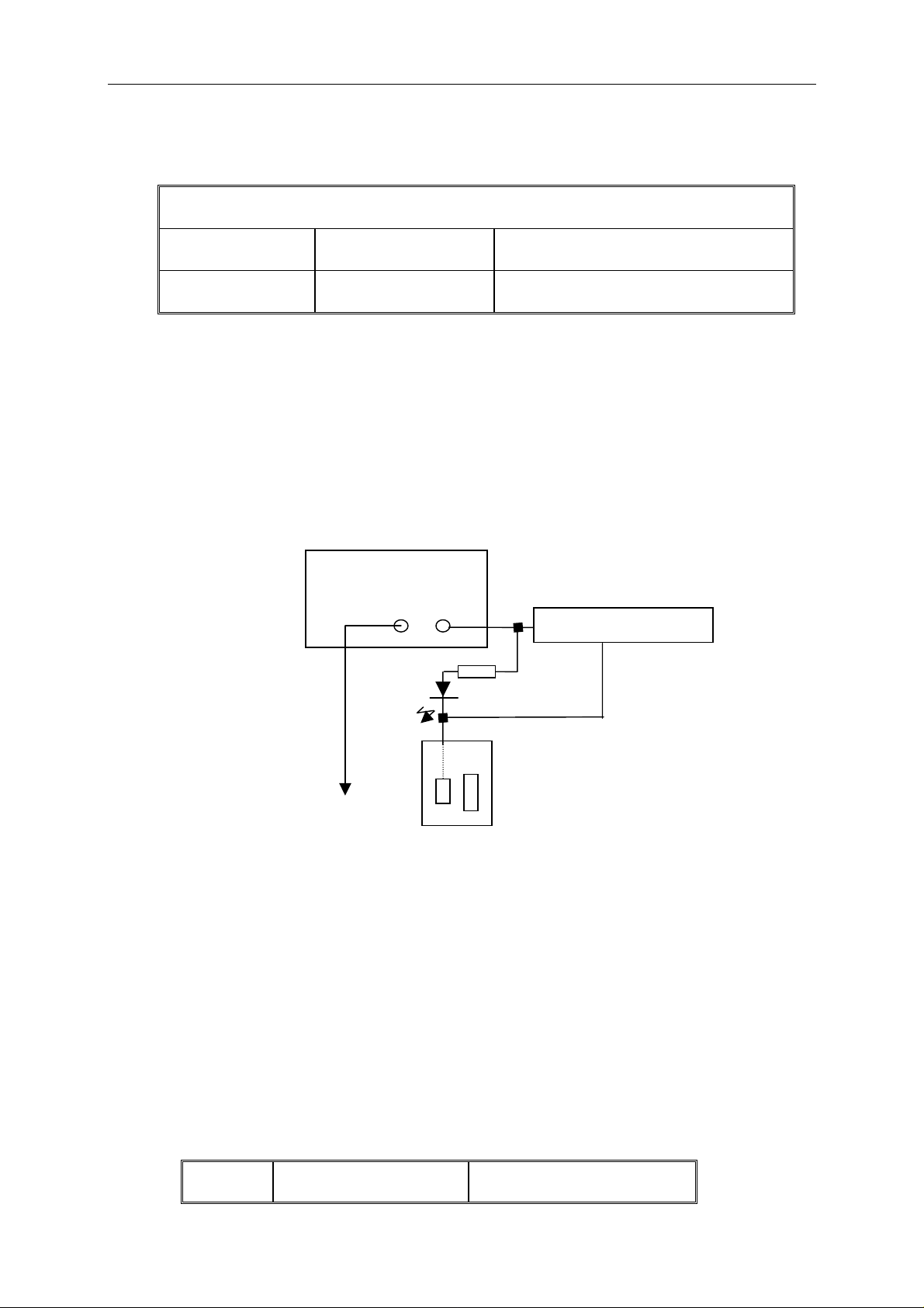
2.10 PS line polarities test
This test only the machines which will sell to NAFTA should be done.
Test method :
Connect as drawing below :
DC Power Supply
9V
- +
Sound clew equipment
DX 2.2k
Power Supply jack M
TO F801
Plug the card power connector plugs to Power Supply jack M, and use multimeter pen
touch F801 random pin, then LED DX should luminescence and clew with sound,
otherwise it is unqualified.
2.11 PS power test
Equipment requirements : Wattmeter
Test method :
a. Input more than 60dB color bar signal, audio 1K Hz, 100% modulation.
b. Brightness and contrast are maximum, adjust the volume to make the audio output
power at 0.5W.
c. Connect the wattmeter to test power consumption of Power Supply.
d. Switch the set to standby mode, and then measure the power consumption of
Power Supply again.
It should satisfy request below :
Type Power Standby power
Page 5
Alignment Procedure
2127P3
21”
14”
61W
5.3W
2.12 High voltage and Ib value limit test( random test )
Equipment requirements :Brandenburg High Voltage Meter (Range: 0 - 40kV)
Beam Current Meter
Input signal type : A 60dB white pattern signal.
Test method :
a. Connect the EHT-meter across the anode and aquadag of the CRT.
b. Connect a beam current meter between the anode of picture tube and EHT-cable
of LOT.
c. Measure the EHT-voltage at zero beam current (I
d. Subsequently, measure the EHT-voltage at respective I
It should satisfy request below :
Beam current
Ib = 50µA
21” 14”
EHT-voltage (KV)
beam
= 0µA).
beam(s) .
Ib=50µA&1200µA
2.13 Heater voltage test ( random test )
Equipment requirements : True RMS Voltmeter
Input signal type : Philips test card ( from 1 mV rms(60dBuV)to 50 mV rms )
Test method :
a. Connect the true RMS voltmeter between the heater .
b. Adjust the brightness and contrast to maximum .
c. Then, test the heater voltage . It may be Vrms
2.14 Main function test (eg, NICAM, BTSC, TELTEXT and etc.)
NICAM test standard please reference
BTSC test standard please reference
TELTEXT test standard please reference Q/WP1259-2003.
CCD、V-CHIP test standard please reference EIA-744-A
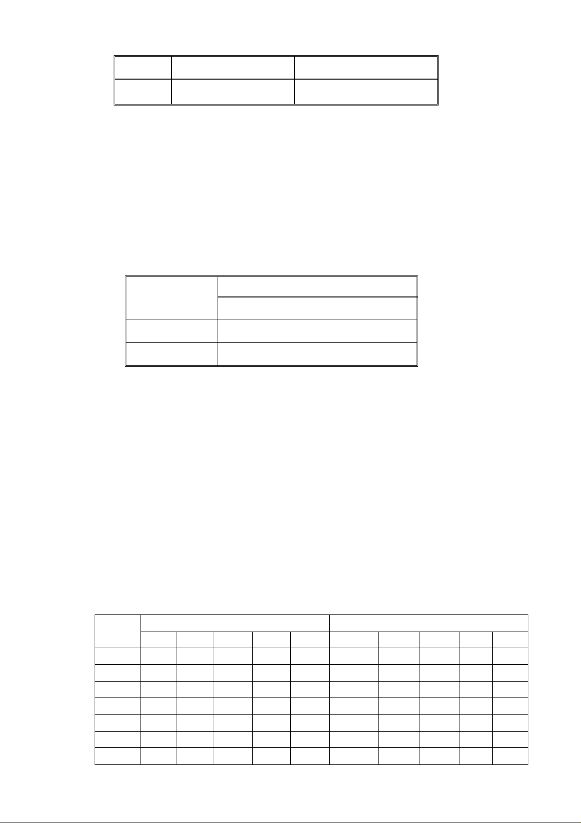
3. EEPROM Data and Address.
Items marked with * are adjustable, the others are not. Take Model 2127 for reference only.
Model
No.
2127P3 32 26 35 23 33 35 35 33 33 31
RED* GRN* WPR* WPB* WPG* 5VPOS* 5VAM* 5VSL* 5VL* 5VSL
KEY1 KEY2
Page 6
Alignment Procedure
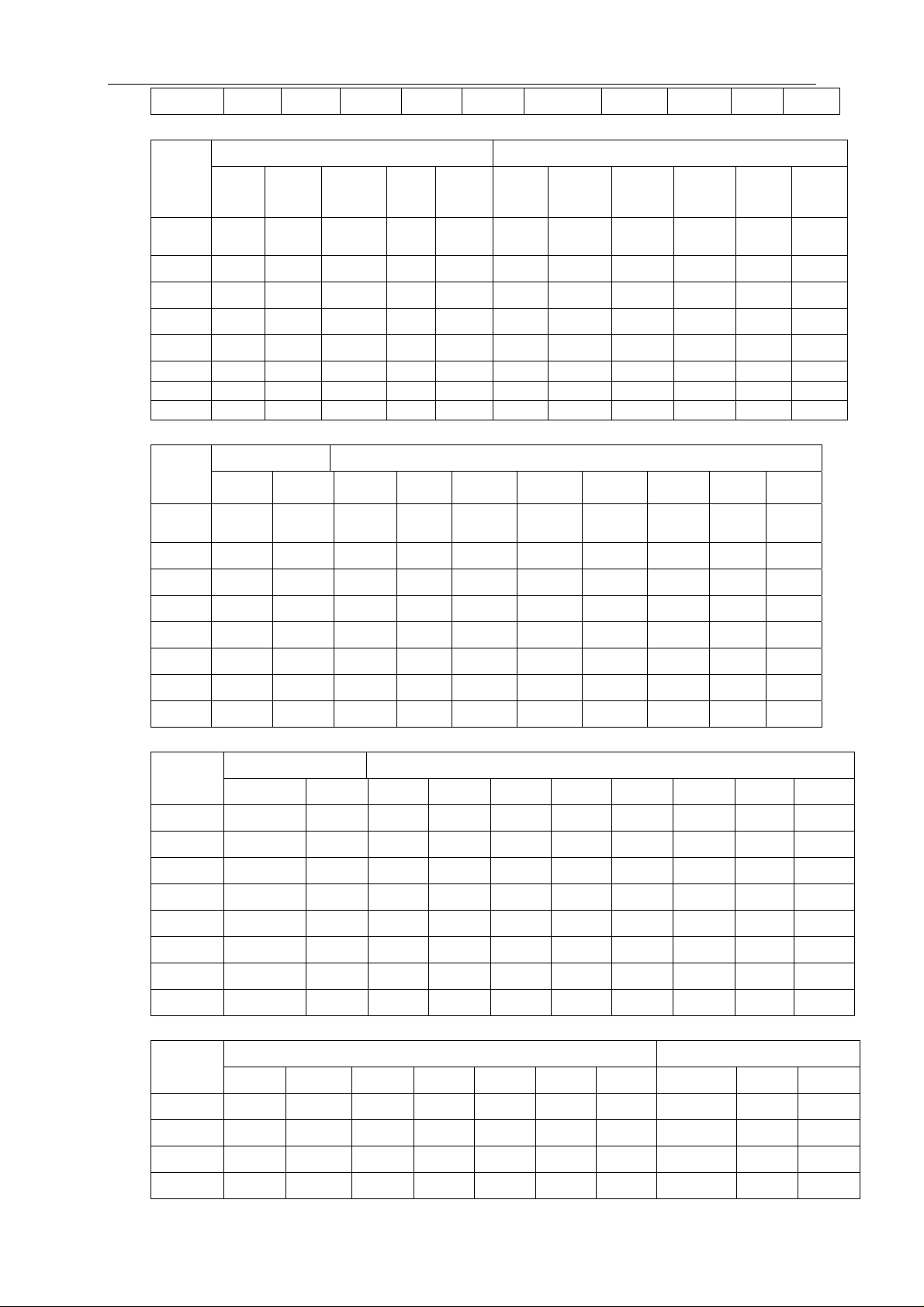
Model
No.
2127
P3
25 5 4 5 5 28 29 41 36 28 48
Model
No.
2127
P3
44 25 20 32 3.5M 3.1M 4.0M 32 32 64
Model
No.
KEY2 KEY3
5BS
*
CPEK
PAL
5BSW
BR*
5SCL* 5WBF
KEY3 KEY4
5LCR* 5EWT*
5WBR*
*
AGC*
WBF
RF
CFPEK
PAL
5HSH
*
CFPEK
5PAR
NTS
5BOW
*
CFPEK
YUV
5EWW* 5WEP* 5UCR
*
IFPL BBTC
PG
R/G/B
KEY4 KEY5
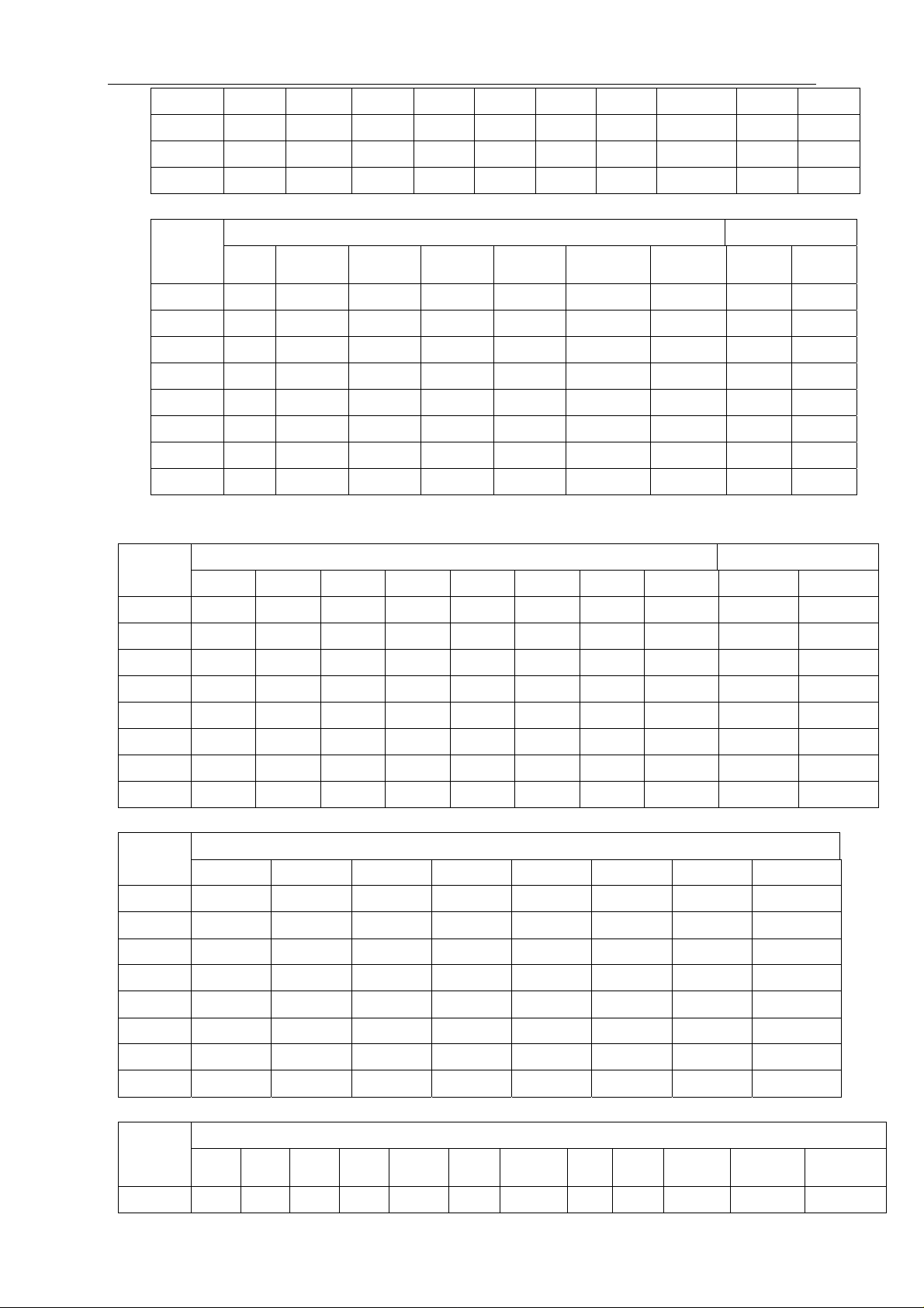
VG2BRI
* HDOL CNTX CNTN BRTX BRTN COLX COLN TNTX TNTN
*
2127P3 20 4 53 2 11 5 63 0 20 12
Model
No.
CNTC BRTC
* COLC TNTC COLP COLS BRTS SHPTV4 SHPX SHPN
KEY6 KEY7
2127P3 25 32 28 30 0 28 0 31 31 31
Page 7
Alignment Procedure
Model
No.
OSD
BRI
5CCDH 5CCDV 5OSDH 5OSDV 5MENUV MENUH OPT1
KEY 7 KEY 8
* OPT2*
2127P3 15 8 35 15 42 18 7 0A 80
Model
No.
* OPT4* OPT5* OPT6* OPT7* OPT8* OPT9* OPT10* MODE1* MODE2*
OPT3
KEY8 KEY9
2127P3 33 0 27 0B 58 0 4 0 26 97
Model
No.
MODE3
* MODE4* MODE5* MODE6* MODE7* MODE8* MODE9* MODE10*
KEY9
2127P3 50 AD 1F 8E 10 22 C2 10
Model
No.
VOL
01
VOL
25
VOL
50
VOL
100
YDFE
PAL
DEC
LVL
KEY0
MONO
LVL
NIC
LVL
ADC
LVL
DCXO
CAPV
*
NICLP
INV*
PSCALE
2127P3 27 121 135 148 15 0 0 0 0 54 Not 0.375
Page 8

Alignment Procedure
inverted
Mode
l No.
2127
P3
PLIM PCENTER
96 212 6 86 30 40 85 30 70 11 4 5
KEY0 KEY NOTEBOOK
* LOUNDESS
BASS TREBLE 300Hz
M S T M S T M S T
KEY NOTEBOOK KEY FAVORITE
Mode
l No.
500Hz 1K Hz 5K Hz 8K Hz Warm* Cool*
M S T M S T M S T M S T R G B R G B
2127
P3
9 7 6 6 6 7 9 7 9 11 4 11 4 0 6 6 0 4
Model
No.
SET
*
P1
SET
P2*
DATA
VL*
DATA
VH*
KEY SLEEP
DATA
UF*
SPE
POSI
SPE
DATA
SENSI
ON
2127P3 147M 423M 1 2 8 0 0 0 0
SENSI
OFF
Page 9
Alignment Procedure
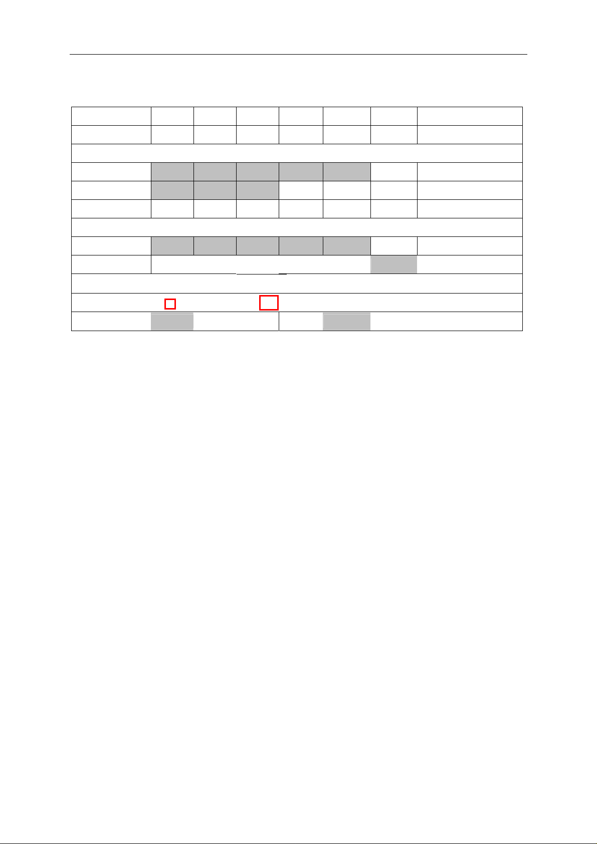
4. White balance address
R G B R AMP G AMP B AMP R CUT G CUT B CUT Remark
Offset DATA 142 143 150 146 161 ***** Factual setup
IC write(LsB)
Sub Add 32 33 34 23 24 *****
Start Bit 6 6 6 6 6 *****
St0p Bit 0 0 0 0 0 *****
E2PROM
Sub Add(LsB) 122 123 124 119 120 *****
Reference
Slave Address(write)
16 Bit EEPROM
IC 138
Page Addr
E2PROM 160
5. CDRH Document ( If available)
6. REMARK
TV standard color TEM
B
BJ SanAi(SWB-301)
The items marked in Grey are invalid for this chassis.
 Loading...