

Page 1

4#,
3%26)#%-!.5!,
LED50UHDE5692G-MS59KV-LA
#AUTION…………………………………………………………………………
SPECIFICATION………………………… ……………………………………… …
!LIGNMENT0RO
ˊ"LOCKDIAGRAM………………………………… ………………………………
ˊ3CHEME$IAGRAM ………………………………… …………………………
4ROUBLESHOOT
0#",AYOUT …… ………
4HISM ANUALI ST HEL ATESTAT T HET IMEOF PR INTING ANDDOE S NOT
INCLUDETHEMODIFICATIONWHICHMAYBEMADEAFTERTHEPRINTINGBY
THECONSTANTIMPROVEMENTOFPRODUCT
CEDURE…………………………………………… ……………
ING…………………………………………… …………………
……………………………………… ……………
Page 2
RISK OF
ELECTRIC
SHOCK DO
NOT
OPEN.
SCHNEIDER ELECTRONICS GMBH-GERMANY
1. CAUTION
CAUTION:
Use of controls, adjustments or procedures other than those specified herein may result in
hazardous radiation exposure.
CA UTION : TO RE DUCE THE RIS K OF
CA U T IO N
RISK
SHOCK
The lighting flash with arrowhead symbol, with an equilateral triangle is intended to
alert the user to the presence of uninsulated voltage within the products
enclosure that may be of sufficient magnitude to constitute a risk of electric shock to
the person.
The exclamation point within an equilateral triangle is intended to alert the user to the
presence of important operating and maintenance (servicing) instructions in the
literature accompanying the appliance.
ELECTRI
NOT
OPEN.
ELECTR ICA L SHOCK, DO NOT REMOVE
COVER (OR BACK). NO USER SERVICEABLE
PAR TS INS IDE. RE FER SER VIC ING T O
QUALIFIE D SERVICE PERS ONNEL.
dangerous
WARNING: TO REDUCE RISK OF FIRE OR ELECTRIC SHOCK, DO NOT
EXPOSE THIS APPLIANCE TO RAIN OR MOISTURE.
2
2
Page 3

SCHNEIDER ELECTRONICS GMBH-GERMANY
IMPORTANT SAFETY INSTRUCTIONS
CAUTION:
Read all of these instructions. Sa ve these instructions for later use . Follo w all W arnings and
Instructions marked on the audio equipment.
1. Read Instructions- All the safety and operatinginstructionsshouldbe read before the productis operated.
2. Retain Instructions- The safety and operating instructions should be retained for future reference.
3. Heed Warnings- All warnings on the product and in the operating instructions should be adhered to.
4. Follow Instructions- All operating and use instructions should be followed.
FOR YOUR PERSONAL SAFETY
1. When the power cord or plug is damaged or frayed, unplug this television set from the wall outlet and refer servicing to
qualified service personnel.
2. Do not overload wall outlets and extension cords as this can result in fire or electric shock.
3. Do not allow anything to rest on or roll over the power cord, and do not place the TV where power cord is subject to
traffic or abuse. This may result in a shock or fire hazard.
4. Do not attempt to service this television set yourself as opening or removing covers may expose you to dangerous
voltage or other hazards. Refer all servicing to qualified service personnel.
5. Never push objects of any kind into this television set through cabinet slots as they may touch dangerous voltage
points or short out parts that could result in a fire or electric shock. Never spill liquid of any kind on the television set.
6. If the television set has been dropped or the cabinet has been damaged, unplug this television set from the wall outlet
and refer servicing to qualified service personnel.
7. If liquid has been spilled into the television set, unplug this television set from the wall outlet and refer servicing to
qualified service personnel.
8. Do not subject your television set to impact of any kind. Be particularly careful not to damage the picture tube surface.
9. Unplug this television set from the wall outlet before cleaning. Do not use liquid cleaners or aerosol cleaners. Use a
damp cloth for cleaning.
10.1. Do not place this television set on an unstable cart, stand, or table. The television set may fall, causing serious injury
to a child or an adult, and serious damage to the appliance . Use only with a car t or stand recommended by the
manufacturer, or sold with the television set. Wall or shelf mounting should follow the manufacturer s instructions, and
should use a mounting kit approved by the manufacturer.
10.2. An appliance and cart combination should be moved with care. Quick stops, excessive force, and uneven surfaces
may cause the appliance and cart combination to overturn.
3
3
Page 4
SCHNEIDER ELECTRONICS GMBH-GERMANY
PROTECTION AND LOCATION OF YOUR SET
11. Do not use this television set near water ... for example, near a bathtub, washbowl, kitchen sink, or laundry tub, in a
wet basement, or near a swimming pool, etc.
Never expose the set to rain or water. If the set has been exposed to rain or water, unplug the set from the wall
outlet and refer servicing to qualified service personnel.
12. Choose a place where light (artificial or sunlight) does not shine directly on the screen.
13. Avoid dusty places, since piling up of dust inside TV chassis may cause failure of the set when high humidity persists.
14. The set has slots, or openings in the cabinet for ventilation purposes, to provide reliable operation of the receiver, to
protect it from overheating. These openings must not be blocked or covered.
Never cover the slots or openings with cloth or other material.
Never block the bottom ventilation slots of the set by placing it on a bed, sofa, rug, etc.
Never place the set near or over a radiator or heat register.
Never place the set in enclosure, unless proper ventilation is provided.
a built-in
PROTECTION AND LOCATION OF YOUR SET
15.1. If an outside antenna is connectedto the television set, be sure the antenna system is grounded so as to provide some
protection against voltage surges and built up static charges, Section 810 of the National Electrical Code, NFPA No.
70-1975, provides information with respect to proper grounding of the mast and supportingstructure, grounding of the
lead-in wire to an antenna discharge unit, size of grounding conductors, location of antenna discharge unit, connection
to grounding electrode, and requirements for the grounding electrode.
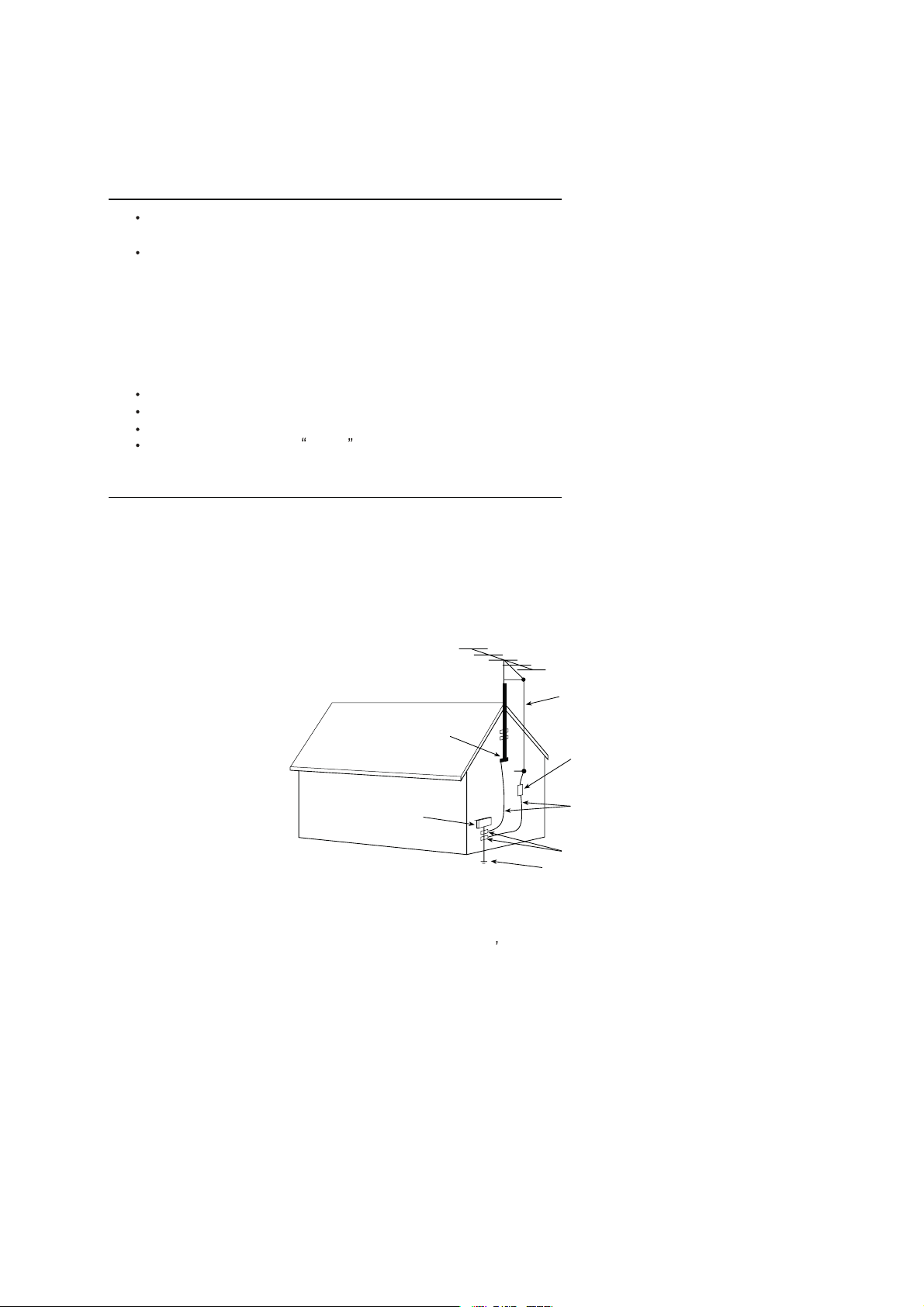
EXAMPLE OF ANTENNA GROUNDING AS PER NATIONAL ELECTRICAL CODE INSTR UCTIONS
EXAMPLE OF ANTENNA GROUNDING AS PER
NATIONAL ELECTRICAL CODE
ANTENNA
LEAD- IN WIRE
GROUND CLAMP
ELECTRIC SERVICE
EQUIPMENT
NEC-NATIONAL ELECTRICAL CODE
ANTENNA DISCHARGE
UNIT (NEC SECTION
810-20)
GROUNDING
CONDUCTORS
(NECSECTION 810-21)
GROUND CLAMPS
POWER SER VICE GROUNDING
ELECTRODE SYSTEM
(NEC ART 250. PART H)
15.2. Note to CATV system installer : (Only for the television set with CATV reception)
This reminder is provided to call the CATV system attention to Ar ticle 820-40 of the NEC that provides
installer s
guidelines for proper grounding and, in particular, specifies that the cable ground shall be connected to the grounding
system of the building, as close to the point of cable entry as practical.
16. An outside antenna system shouldnot be located in the vicinity of overhead power lines or other electric lights or power
circuits, or where it can fall into such power lines or circuits. When installing an outside antenna system, extreme care
should be taken to keep from touching such power lines or circuits as contact with them might be fatal.
17. For added protection for this television set during a lightning storm, or when it is left unattended and unused for long
periods of time, unplug it from the wall outlet and disconnect the antenna. This will prevent damage due to lightning
and power-line surges.
4
4
Page 5

SCHNEIDER ELECTRONICS GMBH-GERMANY
OPERATION OF YOUR SET
18.
This television set should be operated only from the type of power source indicated on the marking label.If you are not
sure of the type of power supply at your home, consult your television dealer or local power company. For television
sets designed to operate from battery power, refer to the operating instructions.
19. If the television set does not operate normally by following the operating instructions, unplug this television set from the
wall outlet and refer servicing to qualified service personnel. Adjust only those controls that are covered in the operating
instructions as improper adjustment of other controls may result in damage and will often require extensive work by a
qualified technician to restore the television set to normal operation.
20. When going on a holiday : If your television set is to remain unused for a period of time, for instance, when you go on
a holiday, turn the television set and unplug the television set from the wall outlet.
off
IF THE SET DOES NOT OPERATE PROPERLY
21. If you are unable to restore normal operation by following the detailedprocedurein youroperating instructions,
do not attempt any further adjustment. Unplug the set and call your dealer or service technician.
22. Whenever the television set is damaged or fails, or a distinct change in performance indicates a need for
service, unplug the set and have it checked by a professional service technician.
23. It is normal for some TV sets to make occasional snapping or popping sounds, particularly when being
turned on or off. If the snapping or popping is continuous or frequent, unplug the set and consult your
dealer or service technician.
FOR SERVICE AND MODIFICATION
24. Do not use attachments not recommendedby the television set manufacturer as they may cause hazards.
25. When replacement parts are required, be sure the service technician has used replacement parts specified
by the manufacturer that have the same characteristics as the original part. Unauthorized substitutions
may result in fire, electric shock, or other hazards.
26. Upon completion of any service or repairs to the television set, ask the service technician to perform
routine safety checks to determine that the television is in safe operating condition.
5
5
Page 6
EM BUSINESS CENTER
y
FTV PRODUCT PLANNING DEPT.
SPECIFICATION
Version: V1.0 Issued Date: 2014.04.11
Model:LE50UHDE5692G/MS59KV
Brand:TCL
PICTURE
Panel Size (inch) 49.5'
Category LED TV(LED BACK LIGHT)
Aspect Ratio
Color Temperature
Backlight Adjustable Yes
Scaler Mode Normal/Full /Zoom/Expand/NoOverscan
Picture Effect Dynamic,Studio,Movie,ENERGYSTAR,Personal
Picture Enhancement TERMINALS
Comb Filter 3D
Core Technolog
MstarACE Yes
Motion Compensation Yes
DLTI Yes
DCTI Yes
Dynamic Skin Tone Correction Yes
DNR Yes
Panel Specification
Panel supplier CMI
Display Resolution 3840*2160
Brightness (cd/m2) 350
Contrast Ratio 5,000,000:1
Response Time 9.5ms
Viewing Angle (H/V) 176 °/176 °
Life Time
Color 1.07 Billion
SOUND TV Channels (Analog)
Speakers Integrated speakers (Bottom side)
Audio Power Output 8W*2
Sound Processing
Dolby Virtual Surround
AVC (Auto Volume Control)
SRS
Sound Features MTS,AVC,Equalizer,Surround
Sound Control Volume, Balance Keyboard Position Back
FUNCTION Base Stand Detachable Yes
Closed Caption Yes
Clock/Timers Yes
Parent Feature Yes
OSD Language English/Spanish/French
OSD Features Non-transparent
HDMI CEC No
USB Connection Yes
Picture Freeze No
3D Function No
GINGA No
IPTV FEATURE 40 feet 294
Browser Yes(Chrome)
YouTube
Google Play Store Yes Operation Manual English(Default)
Vudu Yes Remote Control For TV control
Frequency Yes
Riptide GP Yes Speaker Box Integrated
Go No Wall Mount
MTCL nScreen pro
Wireless Standards
Upgrade Agent(HUAN) Yes Others AC Power cord
Wi-Fi Yes
16:9
Warm / Normal / Cold /User
High-quality scaling engine & 3-D video de-interlacer YPbPr Input 0
30,000hrs TV System ATV:NTSC DTV:ATSC
BTSC (SAP,Stereo,Mono)
DD+ Power Supply 120V,60Hz
Yes Power Consumption-TV on
No Power Consumption-Standby <1w
Yes ACCESSORIES
No WIFI Dongle No
Yes 3D Glasses No
SIGNAL FORMAT CAPABILITY
Component Video Format Up to 720p,1080i@50Hz/60Hz
DVI Video Format Up to 1920x1080 for HDMI-PC
HDMI Video Format Up to 720p,1080i,1080P,4K@30Hz
PC Compatibility N0 VGA
Audio/CVBS Input (Composite) 1 (mini)
Audio Input for YPbPr 0
YCbCr Input 0
Audio Input for YCbCr 0
DVI 0
Headphone 0
HDMI 3
MHL 1 (share with HDMI2)
Audio Output (Composite) 0
SPDIF 1 (optical)
RF Input
USB 3(1---USB3.0, 2---USB2.0)
LAN 1
Basic Info.
AV System NTSC
TV Channels (Digital)
Chassis MS59KV
Certification
Default Color of Front Cabinet Black
Unpackaged Dimension for Main Body (L*H*D) (mm)
With Base Stand (mm) 1127*704.1*230.1
Without Base Stand (mm) 1127*668*65
Packaged Dimension (L*H*D)
Main Body (mm) 1275*800*142
Base Stand Packaged with Main Body
Net Weight (Kg) 22 (With Base Stand)
Gross Weight (Kg) 26
Containe r Loading
20 feet 138
40 feet high 464
Base Stand Packaged with Main Body
1 (F type)
Air 2-69 Cable 1-135
150 Watts
Design and specifications are subject t o c hange without notice!
Drafted by:
Approved by:
Page 7

TCL 多媒体科技控股有限公司
研发中心
文件编号:
共
21 页
YF-Fk07-2013
ALIGNMENT & ELECTRICAL TEST
PROCEDURE
MS59KV
LE50UHDE5692G
Daft
Drafted by Checked by Approved By
贺晓朋
Page 8

CONTENTS
1 POWER SUPPLY......................................................................................................................................... 1
2 ELECTRICAL TEST ................................................................................................................................... 1
2.1 ABBREVIATIONS ...................................................................................................................................... 1
2.2 PREPARATION .......................................................................................................................................... 2
2.3 KEY BOARD, IR RECEIVER AND RC ......................................................................................................... 2
2.3.1 To navigate the MENU using KEYBOARD .................................................................................... 2
2.3.2 To navigate the MENU using REMOTE CONTROL ...................................................................... 3
2.4 VIDEO FUNCTIONAL CHECK ..................................................................................................................... 3
2.4.1 PC ...................................................................................................................
2.4.2 YPbPr .............................................................................................................
2.4.3 HDMI .............................................................................................................................................. 3
2.4.4 RF ................................................................................................................................................... 4
2.4.5 CVBS ............................................................................................................................................... 5
3 VIDEO ALIGNMENT ................................................................................................................................. 5
3.1 ALIGNMENT CONDITIONS ........................................................................................................................ 5
3.2 ADC CALIBRATION ................................................................................................................................. 5
3.3 WHITE BALANCE ..................................................................................................................................... 5
3.3.1 CUT-OFF ALIGNMENT ................................................................................................................ 5
3.3.2 White balance ................................................................................................................................. 6
错误!未定义书签。
错误!未定义书签。
4 AUDIO ALIGNMENT ................................................................................................................................. 7
5 SHOP INITIAL (USELESS) ....................................................................................................................... 7
5.1 SHOP INITIAL SHOULD BE DONE AT THE LAST ALIGNMENT. ..................................................................... 7
6 FACTORY MENU ....................................................................................................................................... 7
6.1 HOW TO ENTER FACTORY MENU BY REMOTE CONTROL ........................................................................... 7
6.2 TO GO BACK OR EXIT FACTORY MENU: .................................................................................................... 7
7 SERVICE MENU ......................................................................................................................................... 7
7.1 HOW TO ENTER SERVICE MENU BY REMOTE CONTROL ............................................................................. 7
7.2 TO GO BACK OR EXIT SERVICE MENU: ...................................................................................................... 7
8 ALL THE D-MODE MENU AND SETTING: .......................................................................................... 8
8.1 MAIN\FACTORY ...................................................................................................................................... 8
8.1.1 White Balance…. ............................................................................................................................ 8
8.2 MAIN\SERVICE MENU .............................................................................................................................. 9
8.3 THE FOLLOWING IC SHOULD BE PRE-COPIED BEFORE SMT PROCESS: ..................................................... 9
8.3.1 How to use USB to update MS59KV ............................................................................................... 9
Page 9
Date 2014/8/13
R&D SHENZHEN
Page 12
Index
of 12 Pages Name
MS59KV is designed for NA Google TV, Dual core CPU and Four core GPU, using Android 4.0 OS and
UI5.0 interface, ore based on intelligent digital cloud TV before increasing the MHL, WIDI and USB3.0.
Support mouse RCU, built-in WIFI.
Draft
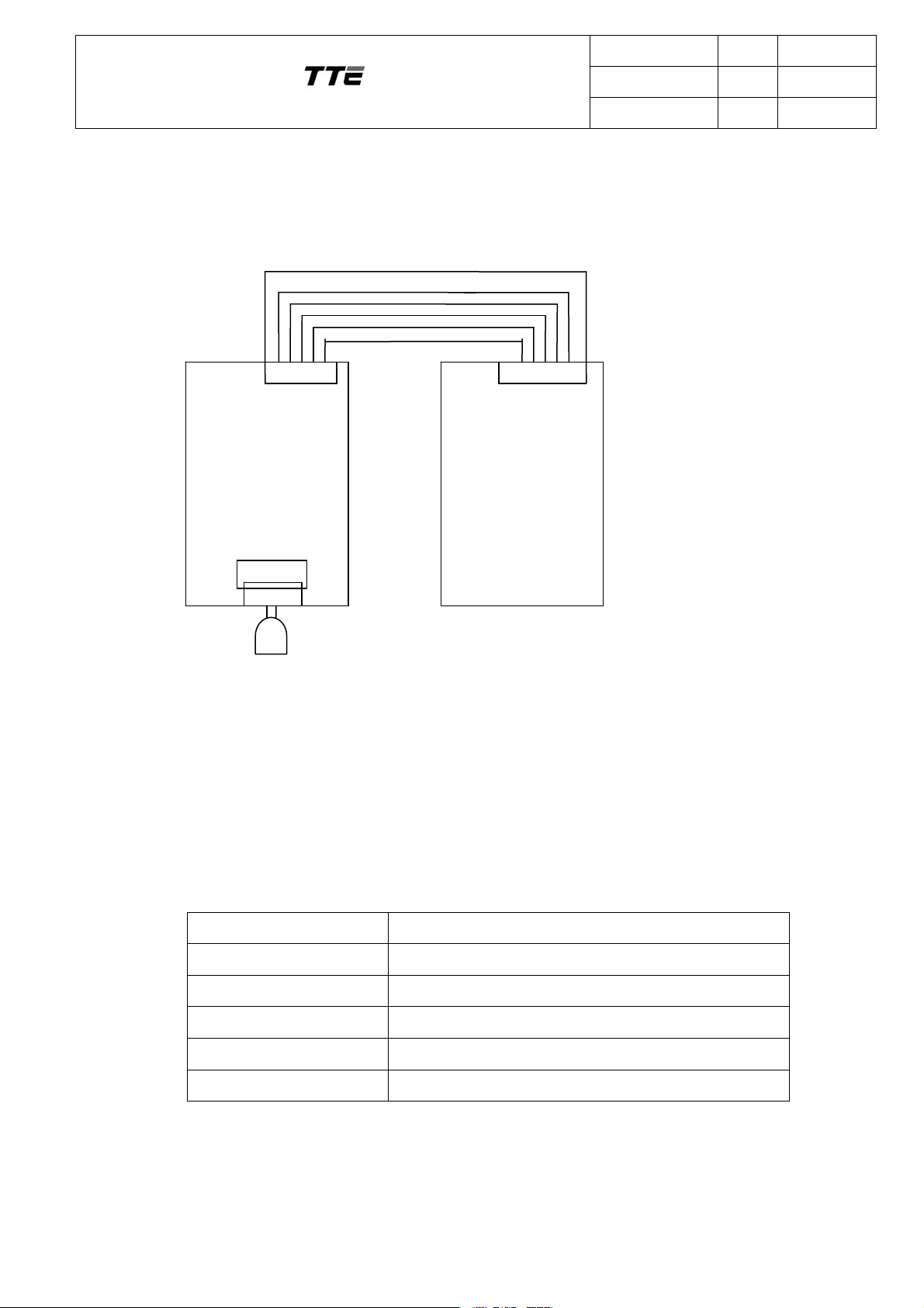
1 Power supply
BLON/OFF;PW_DIM
POWER_ON
GND for +12V
+12V Or +24V
GND for +3V_STB
Main BD(MS59KV)
POWER BD.
AC IN
Mains
P001
All the Model Standard Power supply is +24V and +3.3V for the MainBD.
POWER_ON signal enables the +24and the other Voltage.
If POWER_ON signal = 0V, +24V and the other are not available.
If POWER_ON signal = 3.3V, +24V and the other are available.
2 ELECTRICAL TEST
2.1 Abbreviations
HD High Definition
SD Standard Definition
VGA Video Graphic Adapter
VESA Video Electronics Standards Association
RC Remote Control
TBD To be determined
Page 10

Date 2014/8/13
R&D SHENZHEN
Page 12
of 12 Pages Name
Index
Draft
2.2 Preparation
Connect V-BY-ONE cable from LCD panel to P1401.
Some model need connect +24V supply cables to the inverter unit of panel.
Connect DC/DC&CONTROL cable from Power Board to P001(Main board.).
Connect IR cable from P003 to IR BD.
Connect 2.4G RCU dongle cable to P1005(RC651 MNI1)
Connect KEY cable from P002 to KEYBOARD
Connect SPEAKER cable to P701 & P702.
Connect WIFI cable to P1003.
Connect 3D cable to P905(Some module).
2.3 Key Board, IR receiver and RC
Apply 110V~240V AC to mains input, when power on, LED should off, the LED is Blue
if the TV be in standby mode.
2.3.1 To navigate the MENU using KEYBOARD
A﹥To switch on/off the TV set:
Action: Press Power key on keyboard
Observe: Power key is equal to ON-OFF on remote control.
B﹥To enter MENU Screen:
Action: Press MENU key on keyboard.
Observe: Menu screen should shown at LCD screen.
C﹥During Menu Screen:
Action: Press Menu key
Observe: Menu key is equal to OK key on remote control.
Action: Press Vol- key
Observe: Vol- key is equal to LEFT key on remote control.
Action: Press Vol+ key
Observe: Vol+ key is equal to RIGHT key on remote control.
Action: Press PR- key
Observe: PR- key is equal to DOWN key on remote control.
Action: Press PR+ key
Observe: PR+ key is equal to UP key on remote control.
Page 11
Date 2014/8/13
R&D SHENZHEN
Page 12
of 12 Pages Name
Index
Draft
2.3.2 To navigate the MENU using REMOTE CONTROL
A﹥To enter MENU Screen.
Action: Press MENU key in remote control
Observe: Menu screen should shown at LCD screen.
B﹥During Menu Screen:
Action: Press UP key or DOWN key
Observe: Highlight will goes up and down
Action: Press RIGHT or OK key
Observe: User will enter to the selection highlighted.
Action: Press GO BACK key(shortcut key)
Observe: User will exit from the selection.
2.4 Video functional check
2.4.1 HDMI
2.4.1.1 DVI mode
Standard Monitor Format (VESA)
Connect HDMI cable with TMDS signal in VESA format to P304
Change the display source to HDMI1.
Test Pattern SMPTE 64-step greyscale
(Generated by Quantun881) (Generated by Quantun881)
Format
640x480@60Hz
800x600@60Hz
1024x768@60Hz
1360x768@60Hz
1280x1024@60Hz
640x480@60Hz
800x600@60Hz
1024x768@60Hz
1360x768@60Hz
1280x1024@60Hz
2.4.1.2 HDMI mode
Page 12
Date 2014/8/13
R&D SHENZHEN
Page 12
of 12 Pages Name
Index
Draft
Connect HDMI cable with TMDS signal in VESA format to P304/ P302/ P301.
Change the display source to HDMI 1/ HDMI 2/ HDMI 3
Test
Pattern
SMPTE 64-step greyscale
(Generated by
Quantun881)
(Generated by Quantun881)
Format 4:3 16:9
1H 480i@60HZ 1080i@60Hz
2H 480p@60Hz 720p@60Hz/1080p@60HZ
2.4.1.3 MHL mode
Connect MHL cable to P302
Change the display source to HDMI 2
2.4.2 RF
2.4.2.1 Analog RF signal input
Connect Antenna cable to tuner. TV standard is NTSC-M
Change the display source to TV Channels. The Tuner mode use Antenna or Cable.
Test Pattern
Channel
Depended on
factory
Depended on
factory
Depended on
factory
Picture Frequency
Channel band VHF-L VHF-H UHF
2.4.2.2 Digital RF signal input
Connect Antenna cable to tuner. The digital standard is ATSC.
Change the display source to TV Channels. And Tuner mode must is Antenna.
Test Pattern
Channel
Depended on
factory
Depended on
factory
Depended on
factory
Picture Frequency
Page 13

Date 2014/8/13
R&D SHENZHEN
Page 12
of 12 Pages Name
Index
Draft
Channel band VHF-L VHF-H UHF
2.4.3 CVBS
2.5.5.1 CVBS input
Connect AV cable with CVBS and audio L, R signal to P901 .
Change the display source to CVBS
Test Pattern SMPTE RP-133 32-step greyscale
NTSC M
NTSC M
Format
(Generated by Chroma2327)
(Generated by Chroma2327)
3 Video Alignment
On MS59KV platform, Alignment items could be achieved by using serial port with UART
protocol, P1001(VGA) socket could be used for UART purpose, pin definition as below:
Pin 9----RXD;
Pin 8---TXD;
Before doing the alignment, you must ensure the Project ID is right, this point is very
important.
3.1 Alignment Conditions
In order to have defined conditions for the alignment procedure, the TV set should be
warmed up for 10 minutes.
3.2 ADC Calibration
MS59KV no need any ADC calibration..
3.3 White balance
Only Normal temperature must to been adjusted, the Warm & Cool data will be change
to with some default offset, but these offset also should been changed according to the
manufacture condition. Normally The temperature should been in Appendix 2,
The standard should been decided by customer, Now these data only is reference.
3.3.1 CUT-OFF ALIGNMENT
Cut-off alignment is used to define the color co-ordinates for low luminance level. This
alignment has to be done for the following standards:
1. Insert a grey test pattern with 25IRE signal amplitude
Page 14

Date 2014/8/13
R&D SHENZHEN
Page 12
of 12 Pages Name
Index
Draft
2. Measure the color co-ordinates near the center of the screen
3. Adjust with “R_ Offset”, “G_ Offset” and “B_ Offset” to above color co-ordinates values.
3.3.2 White balance
This alignment has to be done for the following standards:
1. Insert a grey test pattern with 80IRE signal amplitude
2. Measure the color co-ordinates near the center of the screen.
3. Adjust with “R_ Gain”, “G_ Gain” and “B_ Gain” to the following color co-ordinates
values:
Source HDMI CMPT/AV/TV/PC REMARK
Color Temp Normal Normal
R- gain 0~255 -127~+127 Need to adjust
G-gain 128 0 Not need to adjust
B-gain 0~255 -127~+127 Need to adjust
R-offset 0~255 -127~+127 Need to adjust
G-offset 128 0 Not need to adjust
B-offset 0~255 -127~+127 Need to adjust
The default values have a close relation with panel brightness. After white balance
alignment, a picture performance check should be done: the brightest scales of 16scale grey pattern should be distinguishable in vibrant mode (max contrast), and the
light output at OOB( out of box ) use whole white signal (white 100 IRE ),it should
be more than 350nits.
Before white balance alignment, we must make sure White Balance Init had been
done.
The white balance values in normal of HDMI are the base of other value, the other
sources are the offset on Norma of HDMI, so we must adjust normal of HDMI first,
then other source should be adjusted in the end.
Since the White Point and Offset alignments are influencing each other, an
interactive process maybe needed to get both alignments to the required values.
White balance status: picture preset is vibrant, Dynamic Backlight & light sensor is
off.
Page 15

Date 2014/8/13
R&D SHENZHEN
Page 12
of 12 Pages Name
Index
Draft
Advises for adjust while balance: make sure values of “G GAIN” / G OFFSET
using default value ,the Normal temperature should been not adjust .but sometime the
Warm temperature maybe adjust.
4 Audio Alignment
P204: DIGITAL AUDIO OUTPUT (Optical SPDIF OUTPUT)
5 Shop initial
Shop initial should be done at the last alignment.
Enter the factory menu “Factory menu”
Choose “Reset Shop” and press “ok” key on the remote control
Shows “ok” on the screen, exit factory menu, Then power down
The Out Of Box Settings are according to the customer’s requirement.
6 Factory Menu
6.1 How to enter factory menu by remote control
Menu On and inside to Picture Menu
Then inside Picture Setting Menu
And move the cursor to Vedio, select Contrast item.
Press the Password’9735’ (should be finished in 3 seconds)
Press “Go back” key on the remote control directly when FACTORY MODE HOTKEY
set ON (while the character "P" displaying on the blow-left of the screen).
6.2 To go back or exit factory menu:
Press “MENU” key on the remote; the “Cancel” key will exit factory menu directly.
7 Service menu
7.1 How to enter service menu by remote control
Menu On and inside to Picture Menu
Then inside Picture Setting Menu
And move the cursor to Expet Setting, select Contrast item.
Press the Password “1950”
7.2 To go back or exit service menu:
Press “MENU” key on the remote; the “CLEAR” key will exit factory menu directly.
The service menu Item
There is only one item: the project ID, press the Left or right can change the project ID and will display
this project hardware information.
Page 16

Date 2014/8/13
R&D SHENZHEN
Page 12
of 12 Pages Name
Index
Draft
8 ALL THE P-MODE MENU AND SETTING:
8.1 Main\Factory
ITEM STATE COMMENT REMARK
when set On, we can enter
Factory mode
hotkey
OFF
Burning Mode OFF
factory menu with
pressing”OK”on remote
control directly.
Aging mode ON:The
flashingcharacter‘PW’and
the time of aging display on
the below-left of the screen.
Factory out :OFF
Only in TV source will
display noise picture
when WARM-UP set on
Disable on designer mode
Factory out :OFF
ADC .........
White Balance ........
No need
For bright and low
luminance level adjust
Do it at the last position
Reset Shop DO
Initialize production.
of the product line,
HOTKEY will be disable.
Reset All DO
Factory mode data reset
It will be done before
shop initial if need
STB: Standby
Power Mode LAST
ON: power on directly
when plugging in the wire.
LAST: For last memory
Set “On” when aging in
the test, and set “Last”
when factory out.
power on/off mode
Use the USB to Clone
NVM Data From USB or
USB Clone ..............
To USB. we can enter the
menu after pressing”OK”on
remote control directly.
Other ..............
8.1.1 White Balance….
White Balance…
ITEM COMMENT REMARK
White
balance Init
SOURCE HDMI
DO
CMP/PC
/AV
Press ‘OK’on RC to
finish
480i/1024*768
/NTSC-M
must adjust HDMI, the
other maybe not to change
Page 17

Date 2014/8/13
R&D SHENZHEN
Page 12
of 12 Pages Name
Index
Draft
Color
Temp
Normal Normal Each source must adjust normal first.
R GAIN 128(0~255) 0(-128~+128)
G GAIN 128(0~255) 0(-128~+128)
B GAIN 128(0~255) 0(-128~+128)
R Offset 128(0~255) 0(-128~+128)
G Offset 128(0~255) 0(-128~+128)
B Offset 128(0~255) 0(-128~+128)
Picture
Enhance
Off/On
Normal of HDMI is the basic data of white
balance of every source and use the HDMI 1
source.
Normal of other source is the offset on normal of
HDMI too. The AV use the AV 1 source.
The parameter of ATV is same as AV and the
DTV is same as HDMI.
If white balance init is not do, this item will be
On.
Picture
Related
......... .......
No need to change anything, if change, you must
do White balance initial.
8.2 Main\Service menu
Service menu
ITEM COMMENT REMARK
Project ID ……
Need select the project ID
There are many Models
8.3 The following IC should be pre-copied before SMT process:
POSITION IC BOM BOM
FOR U602 (Main BD)
FOR U1201 (Main BD)
FOR U402 (Main BD)
13-FHG6A2-8GB
13-W25Q32-FVB
13-W25Q16-00B
V8-MS59K01-LF1VXXX
V8-MS59K01-LM1VXXX
V8-MS59K01-LB1VXXX
8.3.1 How to use USB to update MS59KV
Software’s name must be MstarUpgrade.bin, this file must be locate on USB root
directory and the other file name can not include the upgrade character.
Power off the TV set. Then insert the USB in the USB port .
Page 18

Date 2014/8/13
R&D SHENZHEN
Page 12
of 12 Pages Name
Index
Draft
Press “Power” key on keyboard,then power On the TV, the set will auto read the
file(upgrade_loader.pkg) from USB . during this process the LED light will be
Flashing Blue color, if the LED change to Blue, then indicate the TV go into
standby mode and upgrade is fail, you need Power On the TV through the remote
control and Again the update.
After about 1minute, the update will be finished and will auto start the TV set.
Page 19

Date 2014/8/13
R&D SHENZHEN
Page 12
of 12 Pages Name
Index
Draft
Appendix1: SURVEY OF INDEX CHANG
Revision Page Survey of index change Changed by Remark
Draft 13 Travel 2014/8/13
Appendix 2: Color Temperature Standard
Mode Normal Cool Warm
LE50UHDE5692G
X:280±5
Y:295±5
X:273±5
Y:283±5
X:312±5
Y:329±5
Page 20

8 7 6 5 4 3 2 1
F
E
D
F
E
D
C
B
A
THIS DRAWING CANNOT BE COMMUNICATED TO UNAUTHORIZED PERSONS COPIED UNLES S PERMITTED IN WRITING
C
B
TCL
WW R&D CENTER TCL MULTIMEDIA TECHNOLOGY HOLDING LTD.
5TH FLOOR.TCL BUILDING.SOUTH NANHAI ROAD
NANSHAN DISTRICT.SHENZHEN.GUANGDONG 518067 CHINA
TEL:+86 755 33312403
NOTE:
45678
...........
PAGE: OF
123
A
FORMAT DIN A3
Page 21

8 7 6 5
4 3 2 1
R050
47R
24V/12V_1
F
DIM_DC
T
T
3V3SB
24V/12V
POWER_ON_OUT
(5)
BL_ON_OUT
(5)
R001
3K3
R004
10K
T
POWER_ON
R002
330R
T
POWER_ON
BL_ON
R003
330R
C005
0.01U C002
C004
0.01U
T
GND
2
10
C003
0.01U
P001
3D_CTRL
24V/12V
GND1
1
34
56
78
9
1112
0.01U
DIM_DC
NC/
T
GNDBL_ON
DIM_PWM
(6)
C001
T
2U2
DIM
GND
R008
NC/
R006
220R
1K
R009
33K
3V3SB
T
DIM_OUT
3V3SB
(5)
24V/12V
3V3SB
L008
0R
L009
0R
C029
220U
35V
GND
24V
C035
0.047U
R005
100K
R010
12K
C027
1000P
C026
NC/
C034
0.1U
220P
R007
68K
5
6
7
8
COMP
FB
SS
EN
U004
9
FSW
VIN
GND
BST
LX
AOZ1284PI
2.2U
24V
2.2U
GND
C020
5V
R011
82K
C072
0.1U
24V
C073
4
3
C028
2
0.1U
10R
R012
1
D003
B540C
GND
L007
6.8UH
10U
C068
C074
10U
Iout=4A
12V
C069
D101
FR2A
3V3SB
(vin=2.7V~6V)
C016
10U
GND
D103
CMS06
5V_DDR_IN
C017
0.1U
L016
1UH
GND
PGND
4
SW
3
VIN
2
PG
1
MP2143
R033
470K
Working frequency:1.2MHz
5V---1.5V/3A
OUT
AGND
10UF
GND
GND
R013
51K
U001
FB
EN
1V5_DDR2
5
6
7
8
24V
T
R048
150K
GND
GND
R049
82K
R021
16K
GND
C064
22U
C065
22U
@max 2A
C086
NC
10U
1V5_DDR
F
GND
4
4
OUT
2
VIN
3
NC/
RD89
10K
B
QD81
GND/ADJ
1
4
4
OUT
2
BT3904NC/
REF
C
E
GND/ADJ
1
CD8E
NC/
C022
0.1U
SS
1000P
GND
QD82
2N7002KNC/
2V5
@max 320mA
C008
10U
3V3
T
3V3
C018
10U
2V5
T
E
D
C
E
GND
GND
GND
3D_DIMMING
3D_PWM
NC/
P103
GND_3D_DIM
4
T
T
3
2
D
1
3D_PWM
3D Switch Control Circuit
R816
4K7
5V
NC/
R828
470R
NC/
R124
10R
3D_DIM
NC/
Q802
C
BT3904
B
NC/
E
R817
10R
NC/
3D_DIM
R825
NC/
0R
GND
3D_DIM_SW
R815
NC/
4K7
NC/
B
Q801
BT3904
C
E
GND
NC/
E
C
R829
470R
3D_DIMMING
Q803
BT3904
NC/
B
DIM_OUT
12
(Vin=3V-28V)
If Input Voltage=24V,CD80/CD81=2.2uF/50V
If Input Voltage=12V,CD80=10uF/16V AND CD81 NC
24V
CD81
CD80
2.2U
2.2U
CD82
0.1U
Vref=0.59V
RD8A 10K
CD83
6800P
RD83
1K2
GND
CD84
0.01U
CD85
2U2
SS
1
2
REF
3
4
5 6
UD80
ILIM
FB
SS
REF
GND
LG BST
HG
SW
MP2905
10RRD82
RD80
4K7
10
9
IN
8
7
0.01UCD86
10RRD81
0.1UCD87
S1
G1
3
S2
4
G2
1
2
QD80
A04832
D1A
D1B
D2A
D2B
RD85
47K
CD89
150P
CD88
8
1U
7
6
5
LD80
6.8UH
CD8A
1000P
RD8B 10K
GND
Change RD85 and CD83 to adjust Fsw, Set Fsw=500kHZ
Change RD80 to adjust OCP,Set OCP=7.6A
GND
If Vout=12V,Set RD84=16K RD83=820R RD85=68K CD8B/CD8C/CD8D=10uF/16V
RD86
6R8
GND
If Vout=5V,Set RD84=9.1K RD83=1.2K RD85=47K CD8B/CD8C=22uF/10V And CD8D NC
24V to 5V DC-DC circuit changed from RT8110D to MP2905 on 2013.03.01
3K6
GND
RD84
9K1
CD8B
22U
R022
CD8C
22U
GND
5V
T
CD8D
NC/22U
@max5A
5V
5V
C021
0.1U
5V
LDO
U002
AS1117-2.5
C019
10U
U003
AS1117-3.3
DD81
10VNC/
RD87
NC/
10K
RD88
NC/
10K
If no power up timing sequence fou +5V,the part circuit NC
VIN
3
GND
C
3V3SB
C061
10K
0.1U
GND
5V
U007
EN/EN# NC
4 3
5V
RT9711A
VIN
5
GND
R065
R064
C078
C085
10U
0.1U
GND
WW R&D CENTER TCL MULTIMEDIA TECHNOLOGY HOLDING LTD.
5TH FLOOR.TCL BUILDING.SOUTH NANHAI ROAD
NANSHAN DISTRICT.SHENZHEN.GUANGDONG 518067 CHINA
TEL:+86 755 33312403
R030
1K
2
GND
D001
C165
NC/
0BAV99NC/
3
0.1U
1
LED
R014
22K
P003
GND
C007
0.1U
GNDGND
7
6
5
4
3
2
1
KEY_IN
close to Socket
LED
T
LIGHT_SENSOR
LOGO
5V
LED
GND
IR
3V3SB
T
(5)
GND
C011
0.1U
R020
100R
T
L_SENSOR
T
GND3
F002
C009
5V_2
T
0.1U
0.1UC012
LOGO
T
C013
0.1U
R017
4K7
NC/
IR
T
470P
R019
100R
C014
GNDGND
5V
LED_OUT
10K
R018
220R
R060
C015
0.1U
L_SENSORL_SENSOR
C010
NC/
0.1U
LOGO_OUT
(5)
IR_IN
(6)
3V3SB
IR_IN
(5)
(5)
5V
C030
0.1U
GND
C032
C031
10U
10U
C033
2U2
GND
Core Power
R025
10R
R061
C058
22U
2K
2K
To IC Inter
C066
22U
Q001
2N7002K
VDDC1V15
C080
C067
22U
NC/
22U
NC/
R069
4K7
VDDC1V15
@max 5A
C071
0.1U
NC
C077
100P
VID1
NC/
R034
L002
0.68UH
0R
33-NLL688-PTX
R028 100K
R027 220K
U008
VCC
SW1
8
IN2
IN3
SS/TRK
BST
PGOOD
7
20
SW2
SW3
AGND
FREQ
21
22
1
2
3
FB
4
5
EN
6
C037
0.1U
GND
C047
1000P
16
171819
PGND8
IN1
15
14
13
12
11
10
PGND7
PGND6
PGND5
PGND4
PGND3
PGND2
MP8606DL
PGND1
9
C036
0.47U
R029
100K
R031
0.1UF
C054
100P
C079
NC/
390P
R035
R066
5K1
100R
R032
5K1
C057
22U
GND
R067
R068
R036
R026
10R
GND
510R
3V3SB1
KEY
3V3SB
R015
T
47K
NC/
P002
GND2
4
T
LED_CTR
T
T
3
KEY
2
1
B
F001
3V3SB
close to D001
C006
0.1U
GND
A
3V3SB3
C025
0.1U
GND
2
GND
1
0R
NC
NC
VOUT
0R
TCL
C060
100U
GND
16V
USB_5V
B
C076
10U
A
GND
GND
GND
NOTE: PAGE:
...........
OF
THIS DRAWING CANNOT BE COMMUNICATED TO UNAUTHORIZED PERSONS COPIED UNLES S PERMITTED IN WRITING
5
4678
3 2 1
FORMAT DIN A2
Page 22

8 7 6 5
TU_3V3
T
1
ANT
3V3
SCL
SDA
GND
XOUT
IF_N
IF_P
IF_AGC
2
3
4
5
6
7
8
9
IFAGC
TU3V3
TUNER-SCL
TUNER-SDA
T
C2065
T2 USE:19-GA0223-JTX
R2041
0.047U
10R
GND
IF_AGC
VIN
3
C2003
0.1U
4
4
OUT
2
GND/ADJ
1
C2004
100U
16V
TU3V3
C2005
0.1U
TUN2
C2006
1U
F
U2001
AS1117-3.3
5V
GND
GND
07-500WF3-SA0G For NA
07-345ZI3-TA0G For EM&AU
GND
E
TU3V3
C2007
10U
C2008
47N
C2012
100P
GND
TUN3
ANT_5V
VCC
I2C_SDA
I2C_SCL
IF_N
IF_P
AGC
1
2
3
4
5
6
7
close to the VCC PIN of tuner
FOR T2:07-600WN3-TY0G
SCL1
T
SDA1
T
TURNKEY DESIGN:19-GA0101-JTX
TUNER_FAT+
IFN
T
IFP
R2046
0R
T
R2047
0R
C2001
33P
TUNER_FATTUNER_FAT+
C2002
33P
TUNER_FAT-
Close to Tuner
TURNKEY DESIGN:19-GA0101-JTX
GND
TUNER-SCL
TUNER-SDA
close to Tuner
C2014
22P
C2015
22P
GND
4 3 2 1
GND
CLOSE TO UM1
R2012
330R
R2013
330R
R2052
820R
C2021
22P
C2020
22P
C2022
0.1U
C2023
0.1U
FAT_IN+
FAT_IN-
(6)
(6)
SCL_T2
SDA_T2
R2048
R2049
100R
R724
100R
4K7
NC
NC
3V3
R700
4K7
close to MSD6369
TUNER_SCL
TUNER_SDA
TUNER_SCL
TUNER_SDA
added on 2013.02.22
FOR T2
R2004
NC/100R
FOR T2
R2005
NC/100R
FOR T2
R2006
100R
R2007
100R
3V3_DEMO
R2002
4K7
TUNER_SCL
TUNER_SDA
R2003
4K7
FOR T2
T2_SCL
T2_SDA
GND
close to T2 DEMOD
close to MSD6369
3V3
R2053
NC/10K
R2050
R2051
C2070
0.022UF
0R
10K
NC
IFAGC
RF_AGC
IFAGC
RF_AGC
IF_AGC
IF_AGC
R2017
NC/0R
R2018
0R/NC
C_IF_AGC
IF_AGC_T2
FOR T2
C_IF_AGC
C_IF_AGC
GND
For models with T2 DEMOD(Vietnam,Sri Lanka etc.), R2017,R2050 NC,R2018 0ohm,C2070 NC
For models without T2 DEMOD(NA,AU,EU,etc), R2017 0ohm,R2050 10Kohm, R2018 0ohm,C2070 0.047uf
(6)
(6)
F
(6)
(6)
E
D
D
3V3_DEMO
R2042
0.1U
FOR T2
1V2_PVDD
NC
4U7
0.1U
C2067
0R
FOR T2
C2063
0.1U
FOR T2
R2043
0R
FOR T2
C2064
0.1U
FOR T2
T2_1V1
FOR T2 DEMO
C2052
FOR T2
3V3_AVDD
3V3_XVDD
TUNER_FAT+
TUNER_FAT-
FOR T2:45-OSC41M-0N0F
10P
C2028
FOR T2
C2029
10P
FOR T2
C2016
C2017
FOR T2
R2008 47R
R2009 47R
FOR T2
FOR T2
1U
1U
FOR T2
CLOSE TO CXD2837
IF_AGC_T2
C2026
0.047U
41M
47P
FOR T2
C2018
FOR T2
FOR T2
1
IN/OUT1
GND1
2
FOR T2
C201947P
R2025
10K
4
GND2
IN/OUT2
3
FOR T2
FOR T2
R2010 0R
R2011
FOR T2
3V3_DEMO
X100
R2029
0R
R2026
T2_RST
R2030
0R
FOR T2
NC
1K
D_IF_AGC
C2027 0.01U
NC
T2RST
1K
3V3_AVDD
1V1_CVDD
T2_SDA
T2_SCL
D_IF_AGC
FOR T2
10K
R2027
T
10P
R2028
200R
FOR T2
T2_MDO7
T2_MDO6
T2_MDO5
T2_MDO4
C2030
FOR T2
C2031 0.1U
FOR T2
3V3_XVDD
1V2_PVDD
1V1_CVDD
T2_MDO3
T2_MDO2
T2_MDO1
FROM T2 DEMO
T2_MDO0
36
XVSS
35
XTALI
34
33
XTALO
XVDD
32
31
NC2
29
30
SLVADR3
NC1
28
CVDD3
RST_X
25
261127
SLVADR0
OSCEN_X
VSS4
T2_MOCLK
T2_MOSVALA
T2_MOSTART
TAINP
37
TAINM
38
AVSS
39
TESTMODE
40
RFAIN
41
AVDD
42
VSS5
43
CVDD4
44
TTUSDA
45
TTUSCL
46
GPIO1
47
TIFAGC
48
U2002
CXD2837ER
FOR T2:13-CD2837-ERB
GPIO0
GPIO2
TSSYNC
TSVALID
TSCLK
VSS1
DVDD1
TSDATA0
TSDATA1
123456789
T2_MDO1
3V3_DVDD
T2_MDO0
T2_MOCLK
T2_MOSVALA
T2_MOSTART
TESTIN
TESTOUT
TSDATA7
TSDATA6
TSDATA5
TSDATA4
TSDATA3
CVDD1
VSS2
TSDATA2
10
12
1V1_CVDD
T2_MDO2
CVDD2
SDA
SCL
DVDD2
VSS3
24
23
22
21
20
19
18
17
16
15
14
13
1V1_CVDD
3V3_DVDD
T2_MDO7
T2_MDO6
T2_MDO5
T2_MDO4
T2_MDO3
SDA_T2
SCL_T2
10P
FOR T2
C2043
10P C2044
added on 2013.02.22
R2031
100R
100R
R2032
FOR T2
FOR T2
FOR T2
SDA
SCL
SCL
SDA
(6)
(6)
TS_VLD
TS_SYNC
NC
10P
C2032
GND
GND
10P
C2033
TS_CLK
NC
GND
NC
10P
C2034
R2038
1
2
3
4 5
R2039
1
2
3
4 5
R2040
1
2
3
4 5
TS_D7
NC
10P
C2035
10R
10R
10R
TS_D6
NC
10P
C2036
FOR T2
FOR T2
FOR T2
8
7
6
TS_D5
NC
10P
C2037
8
7
6
8
7
6
TS_D4
NC
10P
C2038
TS_D3
NC
10P
C2039
TS_D7
TS_D6
TS_D5
TS_D4
TS_D3
TS_D2
TS_D1
TS_D0
TS_CLK
TS_VLD
TS_SYNC
TS_D2
TS_D1
NC
10P
C2040
NC
10P
C2041
(6)
(6)
(6)
(6)
(6)
(6)
(6)
(6)
TO MSD6369 TS
(6)
(6)
(6)
TS_D0
NC
10P
C2042
C
B
3V3_DEMO
10U
C2059
FOR T2
R2044
0R
FOR T2
C2061
0.1U
FOR T2
3V3_DVDD
C2062
0.1U
FOR T2
5V
GND
C2045 0.1U
FOR T2
AZ1084
ADJ/GND
FOR T2
U2003
1
GND
23
VOUTVIN
FOR T2
16V
C2046
220U
3V3_DEMO
C2047
FOR T2
0.1U
GND
C
3V3_DEMO
R2033
2R2
0R
R2045
FOR T2
NC
10U
C2048
FOR T2
GND
0.1U
C2049
FOR T2
4K7
FOR T2
R2034
U2004
8
IN
7
NC3
6
NC2
5
EN
OUT
NC1
ADJ/NC
GND
1
2
3
4
AP7361
FOR T2:13-AP7361-ADB
GND
R2036
0R
FOR T2
R2037
2K7
FOR T2
FOR T2
1K
GND
R2035
GND
10U
C2051
R1=R2=R3=3K3
VOUT=T2_1V2
B
L2002,C2053,C2068 should be close the CVDD pin of CXD2873
0.1uf capacitor should be close to the responding CVDD PIN of CXD2837
T2_1V1
L2002
220R
FOR T2
C2053
FOR T2
220U
6V3
1V1_CVDD
C20550.1U
C2054
FOR T2
FOR T2
10U
C20560.1U
C20570.1U
FOR T2
FOR T2
C20580.1U
FOR T2
C206810U
FOR T2
T2_1V1
NC
FOR CXD2834
L2003
220R
C2066
NC
A
THIS DRAWING CANNOT BE COMMUNICATED TO UNAUTHORIZED PERSONS COPIED UNLES S PERMITTED IN WRITING
GND
SBU :
TCLNO:
Index-Lab
DATE
DESCRIPTION Last modifNAME
Last saved :
5
4678
.............
TCL Thomson Electronics Singapore Pte. Ltd.
8 Jurong Hall Road #28-01/06
The JTC Summit SINGAPORE 609434
DESIGNATION
DRAWN
DESIGNATION
3 2 1
ON:
BY:
Tel (65) 63092900 Fax (65) 63092999
CHECKED
PAGE:
ON:
BY:
OF :
A
FORMAT DIN A2
Page 23

8 7 6 5
HD_R
F
YPBPR_IN
GND-Y
T
HD_R
T
&AV2_IN
P208
NC
wise 20130304
E
P202
NC
wise 20130304
GND
PR/L
GND
PB/R
Y/AV
1
3
R
L
2
4
5
4
3
2
1
HD_R
Y_GND
T
HD_L
HD_PR
HD_PB
HD_Y
GND
NC
NC
NC
F206
R220
75R
HD_Y
HD_L
T T T
HD_L
HD_Y
R208
NC
10K
F204
R210
10K
F205
F207
R221
75R
F208
R222
75R
NC
HD_PB
Close to socket
C248
560P
GND
C249
560P
GND
T
HD_PR
R209
12K
NC
R211
12K
NC
NC
NC
NC
R215
47R
R217
68R
R219
68R
NC
NC
NC
NC
NC
NC
NC
Close to MS6369
NC
NC
NC
NC
C214
0.047U
C216
0.047U
C217
0.047U
NC
C215
1000P
C218
0.047U
R212
47R
R213
47R
R214
47R
R216
10R
R218
68R
C212
0.047U
C213
0.047U
NC
NC
NC
2U2C207
2U2C208
C211
0.047U
NC
NC
HD1_R_IN
HD1_L_IN
HD1_PR_IN
AV2_V_IN
HD1_PB_IN
HD1_Y_IN
HD1_SOG_IN
HD1_PR_INHD1_PB_INHD1_Y_IN-
(6)
(6)
(6)
(6)
(6)
(6)
(6)
(6)
(6)
(6)
USB3_D-_IN
(6)
USB3_D+_IN
(6)
USB_PW_ON
R301
10K
C243
10U
R254
2R2
R255
2R2
GND
R256
1K
5V
C251
0.1U
U_D-
U_D+
F213
F214
4 3
5
GND
(6)
U201
RT9711A
EN/EN# NC
GND
VIN
R257
NC
VOUT
0R
USB3_SSRX-_IN
(6)
USB3_SSRX+_IN
2
GND
1
HD_PR
HD_PB
D
4 3 2 1
R201
100R
C205
560P
SPDIF
close to MS6369
R207
68R
R252
33R
C231
47P
NEARLY U400
C201
0.047U
C202
2U2
C203
2U2
C206
0.047U
C252
100U
16V
R242
2R2
R243
2R2
C253
10U
GND
USB_5V_C
U_SSRXN
U_SSRXP
F201
F202
(6)
(6)
USB_5V_1
USB1_D-
USB1_D+
USB3_SSTX-_IN
USB3_SSTX+_IN
U_SSTXP
USB_5V_C
T
U_SSTXN
U_D-
T
U_D+
T
U_SSRXP
U_SSRXN
GND_USB1
close to socket
AV1_VIN
C241
0.1U
C242
0.1U
GND
USB1 USB3.0
P205
9
1
8
2
7
3
6
4
5
10
11
T
GND
MNT-HOLE1
MNT-HOLE2
U_SSTXN
U_SSTXP
F203
F215
AV1_LIN
AV1_RIN
Optical Fiber
TX
IC
DRIVE
LED
P204
VIN
VCC
GND
3
2
1
C228
0.1U
GND
3V3
R203
10K
R202
10K
R205
12K
SPDIF_3V3
T
T
GND-SPDIF
GND
C204
560P
R206
12K
SPDIF
T
3V3
AV1_V_IN
AV1_L_IN
AV1_R_IN
VCOM0
SPDIF_OUT
F
(6)
(6)
(6)
(5)
E
D
5V
C220
0.1U
GND
AVOUT1_R
C
E
Q203
BT3904
T
21
21
21
FOR AV_OUT
R225
1K
R226
4K7
C222
FOR AV_OUT
closely to IC
AVOUT1_L_OUT
FOR AV_OUT
AVOUT1_V
AVOUT1_L
T
AVOUT1_R
T
R229
470R
FOR AV_OUT
FOR AV_OUT
B
FOR AV_OUT
1U
TRANSISTOR
GND
C238
220P
GND
C235
2U2
FOR AV_OUT
C234
2U2
FOR AV_OUT
FOR AV_OUT
C
Q201
BT3904
E
FOR AV_OUT
R227
150R
FOR AV_OUT
FOR AV_OUT
AVOUT1_L
AVOUT1_R
FOR AV_OUT
Q202
E
BT3906
B
C
FOR AV_OUT
R228
220R
C223
100U
16V
FOR AV_OUT
GND
R249
22K
R237
10K
FOR AV_OUT
FOR AV_OUT
R230
75R
AVOUT1_V
R231
470R
FOR AV_OUT
R238
1K
FOR AV_OUT
C246
150P
FOR AV_OUT
R250
6K8
FOR AV_OUT
C227
1500P
TRANSISTOR
NC/FOR AV_OUT
C
B
E
R251
7K5
FOR AV_OUT
GND
12V
AVOUT1_L
Q204
BT3904
FOR AV_OUT
(6)
HP_L
(6)
HP_R
3V3
(6)
HP_DET
C209
0.1U
FOR HP
GND
Headphone out
Connected=L
Disconnected=H
close to MS6369
FOR HP
10K
R223
10K
R204
FOR HP
(9)
(16)
L201
10UH
L202
10UH
FOR HP
HP_DET
4K7
4K7
R246
R247
NC/FOR HP
RESET
HP_DET
close to headphone socket
F328
F327
HP_L
F329
GND
T
T
HP_R
GND
AMP_RESET
BLA_RST
FOR HP
T
R239
FOR HP
FOR HP
C210 10U
GND
R240
220R
220R
C221 10U
R245
100R
R241
100R
NC/FOR HP
C224
22U
FOR HP
C225 22U
FOR HP
FOR HP
FOR HP
TCL
WW R&D CENTER TCL MULTIMEDIA TECHNOLOGY HOLDING LTD.
5TH FLOOR.TCL BUILDING.SOUTH NANHAI ROAD
NANSHAN DISTRICT.SHENZHEN.GUANGDONG 518067 CHINA
TEL:+86 755 33312403
NOTE: PAGE:
...........
5
4
L
GND
3
R
2
CVBS
1
T
HPGND
P201
FOR HP
wise 20130306
OF
C
B
A
AVOUT1
GND-VGA
T
VGA_TXD
VGA_RED
F312
F313
GND
17
6
VGA_TXD
11
VGA_RED
1
7
VGA_SDA
12
VGA_GRN
2
8
VGA_HS
13
VGA_BLU
3
9
VGA_VS
14
VGA_RXD
4
10
VGA_SCL
15
5
16
VGA_SDA
VGA_GRN
F315
F314
F316
VGA_RED
VGA_HS
VGA_VS
VGA_HS
VGA_BLU
F318
F317
VGA_TXD
T
T
VGA_SDA
T
T
VGA_GRN
T
T
VGA_BLU
T
VGA_VS
VGA_RXD
T T
VGA_SCL
VGA_SCL
VGA_RXD
F320
F319
GND
R355
75R
FOR VGA
15-pin
12-pin
11-pin
4-pin
R356
75R
FOR VGA
VGA_SCL
VGA_SDA
VGA_TXD
VGA_RXD
Close to socket Close to MS6369
R349
33R
FOR VGA
33R
R351
10R
FOR VGA
R353
33R
FOR VGA
R359
R358
R357
75R
FOR VGA
2K2
FOR VGA
GND
R339
R341
R344 100R
R345 100R
2K2
FOR VGA
FOR VGA
FOR VGA
FOR VGA
FOR VGA
VGA_RED_IN-
VGA_GRN_IN-
VGA_BLU_IN-
100R
100R
R350
FOR VGA
UART_TX
UART_RX
C350
0.047U
FOR VGA
C351
0.047U
FOR VGA
R352
100R
FOR VGA
R354
100R
FOR VGA
FOR VGA
FOR VGA
C355 0.047U
C354 0.047U
FOR VGA
FOR VGA
C352
1000P
C353
0.047U
0.047UC356
FOR VGA
R346
R347
R348
VGA_RED_IN
VGA_GRN_IN
VGA_SOG_IN
VGA_HS_IN
VGA_BLU_IN
VGA_VS_IN
FOR VGA
FOR VGA
FOR VGA
68R
68R
68R
GND
closely to IC
AVOUT1_R_OUT
C239
220P
FOR AV_OUT
GND
FOR AV_OUT
P203
AVOUT1_V_OUT
(5)
R234
22K
R233
10K
FOR AV_OUT
C226
1500P
FOR AV_OUT
CVBS
1
R
2
GND
3
L
4
5
R235
6K8
FOR AV_OUT
FOR AV_OUT
GND-AVOUT
FOR VGA
C
P303
B
A
AV OUT
GND
C219
1U
FOR AV_OUT
R224
1K
FOR AV_OUT
R232
1K
FOR AV_OUT
NC/FOR AV_OUT
C247
150P
R236
7K5
TRANSISTOR
GND
T
F209
FOR AV_OUT
NC/FOR AV_OUT
F211
NC/FOR AV_OUT
B
AVOUT1_V
R305
F210
R307
R308
THIS DRAWING CANNOT BE COMMUNICATED TO UNAUTHORIZED PERSONS COPIED UNLES S PERMITTED IN WRITING
5
4678
3 2 1
FORMAT DIN A2
Page 24

8 7 6 5
4 3 2 1
HB_5V
D301
BAT54C
1 2
3
F
HA_5V
HPD
VCC
GND5
DDCDA
DDCCLK
NC2
NC1
RXC-
E
GND4
RXC+
RX0-
GND3
RX0+
RX1-
GND2
RX1+
RX2-
GND1
RX2+
P301
HDMI3
HA_HPD
19
18
17
16
15
14
13
12
11
10
9
8
7
6
5
4
3
2
1
GND
HDMI Matching Resistor close to Jack
R378
47K
HA_5V
H1_SCL H3_SCL
HA_CEC
R431 5R1
2
R439 5R1
2
R442 5R1
2
R451
2
5R1
R306
0R
R379
47K
41
3
41
3
41
3
41
3
R303
100R
R304
100R
HA_RXC-_IN
HA_RXC+_IN
HA_RX0-_IN
HA_RX0+_IN
HA_RX1-_IN
HA_RX1+_IN
HA_RX2-_IN
HA_RX2+_IN
HA_SDA
HA_SCL
HDMI_CEC
(5)
HPD
VCC
GND5
DDCDA
DDCCLK
NC2
NC1
RXC-
GND4
RXC+
RX0-
GND3
RX0+
RX1-
GND2
RX1+
RX2-
GND1
RX2+
P304
HDMI1
HC_HPD
19
HC_5V
18
17
16
15
14
13
12
11
10
9
8
7
6
5
4
3
2
1
GND
HDMI Matching Resistor close to Jack
H3_SDAH1_SDA
R459 5R1
HC_5V
R314
47K
2
R472 5R1
2
R484 5R1
2
R485 5R1
2
R318
0R
R315
47K
41
3
41
3
41
3
41
3
R316
100R
R317
100R
HC_RXC-_IN
HC_RXC+_IN
HC_RX0-_IN
HC_RX0+_IN
HC_RX1-_IN
HC_RX1+_IN
HC_RX2-_IN
HC_RX2+_IN
HDMI_CECHC_CEC
HC_SDA
HC_SCL
(5)
HB_SDA
R329
100R
(5)
HB_SCL
HDMI_CEC
HB_RXC-_IN
HB_RXC+_IN
HB_RX0-_IN
HB_RX0+_IN
HB_RX1-_IN
HB_RX1+_IN
5R1
HB_RX2-_IN
HB_RX2+_IN
4 1
3
HDMI Matching Resistor close to Jack
D
R377
10K
R328
100R
R382
0R
4 1
3
4 1
3
4 1
3
R40A
2
6M40_5V
AVDD5V_CD
R327
4K7
HB_CEC
5R1
R486
R4875R1
R4005R1
MHL_CD_SENSE
HB_HPD
HB_5V
H_ARC
2
2
2
H2_SDA
H2_SCL
GND
19
18
17
16
15
14
13
12
11
10
9
8
7
6
5
4
3
2
1
HPD
VCC
GND5
DDCDA
DDCCLK
NC2
NC1
RXC-
GND4
RXC+
RX0-
GND3
RX0+
RX1-
GND2
RX1+
RX2-
GND1
RX2+
P302
HDMI2 MHL
F
E
D
MHL_CD_SENSE
H_ARC
F301
HA_5V
F302
HA_CEC
F303
HA_HPD
F304
H3_SDA
H3_SCL
F305
F306
HB_5V
F307
HB_HPD
HB_CEC
F308
F309
H2_SDA
H2_SCL
F310
F311
F321
DVDD33
DVDD33
AVDD10
HA_RXC-_IN
HA_RX0-_IN
HA_RXC+_IN
HA_RX0+_IN
HA_RX1-_IN
HA_RX2-_IN
HA_RX1+_IN
HA_RX2+_IN
R1PWR5V
R433
1U
C
5K6
C456
10R
HA_5V
HB_RX2-_IN
HB_RX1+_IN
HB_RX2+_IN
767473
75
HB_RX1-_IN
HB_RX0-_IN
HB_RX0+_IN
HB_RXC+_IN
69
70
68
72
71
HB_RXC-_IN
66
65
64
67
GND
wise 20130304
59
58
60
63
62
61
HC_5V
F322
HC_CEC
HC_HPD
F323
H1_SDA
H1_SCL
F324
F325
F326
wise 20130304
MHL_CD_SENSE
C491 0.047U
GND
6M40_5V
R532 300K
R531
100R
H_ARC
GND
C301
1U
4 3
C489 10U
0.1UC490
R475
0R
NC/
R530
G524
EN/EN# OC
U401
H_ARC_OUT
0R
15
OUTIN
2
GND
(5)
HB_5V
10UC492
GND
GND
C
R434
wise 20130304
GND
R2PWR5V HB_5V
R437
10R
1U
5K6
C457
R435
GND
R3PWR5V
B
1U
R332
10R
HC_5V
HC_RXC-_IN
HC_RXC+_IN
HC_RX0-_IN
HC_RX0+_IN
DVDD10
TXAVDD10
M_TX2+_OUT
(13)
M_TX2-_OUT
(13)
M_TX1+_OUT
(13)
M_TX1-_OUT
(13)
M_TX0+_OUT
(13)
M_TX0-_OUT
(13)
M_TXC+_OUT
(13)
M_TXC-_OUT
(13)
AVDD10
HC_RX1-_IN
HC_RX1+_IN
HC_RX2-_IN
HC_RX2+_IN
1
2
3
4
5
6
7
8
9
10
11
12
13
14
15
16
17
18
19
AVDD10A
R3XCN
R3XCP
R3X0N
R3X0P
R3X1N
R3X1P
R3X2N
R3X2P
VDD10A
TAVDD10
TX2P
TX2N
TX1P
TX1N
TXOP
TX0N
TXCP
TXCN
5K6
C324
R333
GND
wise 20130304
13-SI9687-00B
R440
4K7
R2X2P
R2X2N
VDD33B
R2X1P
R2X1N
R2X0P
R2X0N
R2XCP
R2XCN
R1X2P
R1X2N
R1X1P
U403
SII9687
RSVDL
INT
RESET_N
CD_SENSE
DSDA4
DSCL4
DSDA3
DSCL3
CBUS_HPD3
R3PWR5V
TPWR_CI2CA
2122232425262728293031323334353637
20
R533
R461
R476
SII_RST
100R
10K
10K
MHL_CD_SENSE
DSDA2
HC_HPD
HC_SCL
HB_SDA
R3PWR5V
wise 20130304
HB_SCL
HC_SDA
GND
DVDD33
A
R1X0P
R1X0N
R1X1N
DSCL2
CBUS_HPD2
R2PWR5V
HB_HPD
HA_SDA
R2PWR5V
R1XCN
R1XCP
VDD33A
AVDD10B
SPDIF_IN
PWRMUX_OUT
R0PWR5V
CBUS_HPD0
DSDA1
DSCL1
CBUS_HPD1
R1PWR5V
38
HA_HPD
HA_SCL
R1PWR5V
R0X2P
R0X2N
R0X1P
R0X1N
R0X0P
R0X0N
R0XCP
R0XCN
VDD10B
ARC
CSCL
CSDA
SBVCC5
DSCL0
DSDA0
57
56
55
54
53
52
51
50
49
48
47
46
45
44
43
42
41
40
39
PWRMUX_OUT
R387
10K
10K
R388
GND
DVDD10
C458
0.1U
C459
10U
R458
R454
R441
33R
33R
10R
R497 4K7
DVDD33
GND
R447
SII_RST
10K
PWRMUX_OUT
Q402
BT3904
C
E
GND
B
R443
5K6/NC
wise 20130304
R444
10K
C462
0.1U
SII9587_RESET
C463
10U
GND
R498
4K7
L401
120R
DVDD33
9587_SCL
9587_SDA
(6)
(6)
6M40_5V
6M40_5V
+2.5V_6M40
C410
10U
0.1U
C405
GND
U405
AS1117-3.3
C406
22U
C407
0.1U
VIN
L402
120R
1V2
4K7
R383
R389
1K
8
IN
7
NC3
6
NC2
5
ADJ/NC
EN
AP7361
9687_1V0_EN
U404
OUT
NC1
GND
1
2
3
4
Vref=0.8V
GND
R385
33K
10K
R384
22U
GND
C486
0.1U
C488
Need 255mA
9687_1V0
FOR 9687
9687_1V0
T
250mA max
C465
220U
16V
C466
0.1U
L404
120R
L405
120R
10UC467
10UC471
0.1UC468
0.1UC472
R386
6K8
4
4
GND/ADJ
OUT
1
2
3
3V3SII
3V3_9687
T
GND
3V3_9687
L407
120R
220mA max
DVDD33
10UC475
0.1UC476
0.1UC469
0.1UC473
C461
0.1UC470
10U
0.1UC474
15mA max
TCL
0.1UC482
C439
0.1U
C448
100U
16V
Need 250mA
C479 10U
10UC480
10UC481
0.1UC483
WW R&D CENTER TCL MULTIMEDIA TECHNOLOGY HOLDING LTD.
5TH FLOOR.TCL BUILDING.SOUTH NANHAI ROAD
NANSHAN DISTRICT.SHENZHEN.GUANGDONG 518067 CHINA
TEL:+86 755 33312403
10UC477
TXAVDD10
AVDD10
110mA max
DVDD10
100mA max
B
A
GND
GND
NOTE: PAGE:
...........
OF
THIS DRAWING CANNOT BE COMMUNICATED TO UNAUTHORIZED PERSONS COPIED UNLES S PERMITTED IN WRITING
5
4678
3 2 1
FORMAT DIN A2
Page 25

12 11 10 9 8 7 6 5 4 3 2 1
1V5_DDR
U400
H
VGA_RED_INVGA_RED_IN
VGA_GRN_INVGA_GRN_IN
VGA_BLU_INVGA_BLU_IN
VGA_SOG_IN
VGA_HS_IN
VGA_VS_IN
HD1_PR_INHD1_PR_IN
HD1_Y_INHD1_Y_IN
HD1_PB_INHD1_PB_IN
HD1_SOG_IN
G
F
HDMITX_0N
(12)
HDMITX_0P
(12)
HDMITX_1N
(12)
HDMITX_1P
(12)
HDMITX_2N
(12)
HDMITX_2P
(12)
HDMITX_CLKN
(12)
HDMITX_CLKP
(12)
E
H_ARC_OUT
(4)
HDMI_CEC
(4)
D
C402
27P
C403
27P
GND
3V3
GPIO PULL UP
R445
4K7
R446
4K7
R448
4K7
R449
C
3V3SB
4K7
R450
NC/
22K
M3
M2
M1
N3
N1
R6
R5
H2
G2
H3
R3
R2
R1
N2
U5
U4
U6
G3
G1
D2
N6
M6
R4
M5
L2
K2
L3
T6
K3
K1
P4
T5
P5
P2
T3
T1
P3
E2
F3
F2
F1
E3
P6
U400
W3
RIN0M
V1
RIN0P
V2
GIN0M
V3
GIN0P
U3
BIN0M
T2
BIN0P
U2
SOGIN0
Y4
HSYNC0
Y5
VSYNC0
AA1
RIN1M
AA2
RIN1P
AA3
GIN1M
Y2
GIN1P
W2
BIN1M
W1
BIN1P
Y3
SOGIN1
AD2
RIN2M
AD3
RIN2P
AC2
GIN2M
AC3
GIN2P
AB1
BIN2M
AB3
BIN2P
AB2
SOGIN2
AA5
HSYNC1
Y6
VSYNC1
MSD6A901IV
U400
A_RX0N
A_RX0P
A_RX1N
A_RX1P
A_RX2N
A_RX2P
A_RXCN
A_RXCP
DDCDA_CK
DDCDA_DA
HOTPLUGA
B_RX0N
J3
B_RX0P
J2
B_RX1N
J1
B_RX1P
B_RX2N
B_RX2P
B_RXCN
B_RXCP
DDCDB_CK
DDCDB_DA
HOTPLUGB
C_RX0N
C_RX0P
C_RX1N
C_RX1P
C_RX2N
C_RX2P
C_RXCN
C_RXCP
DDCDC_CK
DDCDC_DA
HOTPLUGC
D_RX0N
D_RX0P
D_RX1N
D_RX1P
D_RX2N
D_RX2P
D_RXCN
D_RXCP
DDCDD_CK
DDCDD_DA
HOTPLUGD
PAD_ARC0
CEC
MSD6A901IV
X24M
24M
SDA
3D_CTRL
3D_DIM_SW
SII9587_RESET
SCL
RGB
Audio
Analog
XTALIN
R402
1M
XTALOUT
PHY
USB
CVBS
HDMI
A5
RN
B5
RP
C5
TN
B4
TP
C4
GPIO19
A3
GPIO20
A2
DM_P0
B2
DP_P0
B1
DM_P1
C2
DP_P1
AK5
DM_P2
AM6
DP_P2
AK7
DM
AL8
DP
AK8
SSRXN
AM8
SSRXP
AL7
SSTXN
AK6
SSTXP
VCOM0
AB5
AC5
AB6
AB4
AA6
AC4
AD5
LINE_IN_0L
LINE_IN_0R
LINE_IN_1L
LINE_IN_1R
LINE_IN_2L
LINE_IN_2R
LINE_IN_3L
LINE_IN_3R
HP_OUT_1L
HP_OUT_1R
LINE_OUT_0L
LINE_OUT_0R
LINE_OUT_2L
LINE_OUT_2R
I2S_OUT_BCK
I2S_OUT_MCK
I2S_OUT_WS
I2S_OUT_SD
I2S_IN_BCK
I2S_IN_WS
I2S_IN_SD
XTALOUT
TESTPIN
CVBS3P
CVBS2P
CVBS1P
CVBS0P
CVBS_OUT1
CVBS_OUT2
I2S
SPDIF
SPDIF_IN
SPDIF_OUT
AUVRM
AUVRP
AUVAG
10U
C411
Close to IC with width trace
USB1_D-_IN
USB1_D+_IN
USB0_D-_IN
USB0_D+_IN
USB2_D-_IN
USB2_D+_IN
USB3_D-_IN
USB3_D+_IN
USB3_SSRX-_IN
USB3_SSRX+_IN
USB3_SSTX-_IN
USB3_SSTX+_IN
AV2_V_IN
AV1_V_IN
AVOUT1_V_OUT
AD1
AE3
AE1
AE2
AF3
AF2
AF4
AF5
AD6
MIC_IN
VRP
VAG
VRM
IRINT
RESET
XTALIN
0.1U
C412
0.1U
C413
AC6
AK4
AL4
AG4
AG5
AH4
AH5
AE5
AE4
AE6
H7
H5
H4
H6
E6
E5
F6
M4
D5
AM2
AM3
N9
G6
G5
MIC_CM
RN
RP
TN
TP
JM_CS
JM_DA
VCOM0
HD1_L_IN
HD1_R_IN
AV1_L_IN
AV1_R_IN
KARA_OK
MIC_CM
AVOUT1_L_OUT
AVOUT1_R_OUT
AUVRP
AUVAG
AUVRM
I2S_BCK
I2S_MCK
I2S_LRCK
I2S_DATA
XTALIN
XTALOUT
GND
10U
C414
L403
120R
GND
(4)
C455
2U2
HP_L
HP_R
UART_RX2
UART_TX2
T2_RST
IR_IN
MCU_RESET
3D_FLAG_6M40
SPDIF_OUT
3D_RESET_OUT
RESET
GND
(4)
(4)
(4)
(12)
BLA_TXD
(16)
BLA_RXD
(16)
L_SENSOR
PCM_D0
PCM_D1
PCM_D2
PCM_D3
PCM_D4
PCM_D5
PCM_D6
PCM_D7
PCM_A0
PCM_A1
PCM_A2
PCM_A3
PCM_A4
PCM_A5
PCM_A6
PCM_A7
PCM_A8
PCM_A9
PCM_A10
PCM_A11
PCM_A12
PCM_A13
PCM_A14
PCM_RESET
PCM_IRQA_N
PCM_IOWR_N
PCM_OE_N
PCM_WAIT_N
PCM_IORD_N
PCM_CD_N
PCM_REG_N
PCM_WE_N
PCM_CE_N
SD2_CLK
SD2_CMD
USB_PW_ON
NAND_ALE
NAND_WPZ
NAND_CEZ
NAND_CE1Z
NAND_CLE
NAND_REZ
NAND_WEZ
NAND_RBZ
NAND_D4
NAND_D6
NAND_D5
wise 20130304
CFG-PWM0
CFG-PWM1
DIM_OUT
3D_CTRL
LOGO_OUT
KEY_IN
JM_CK
HP_DET
(14)
INT0
SPI_SCK
SPI_SDI
SPI_SDO
SPI_CSN
VID1
UART_RX
UART_TX
SCL
SDA
3D_DIM_SW
PANEL_ON
POWER_ON_OUT
BL_ON_OUT
POW_PM
SD_WP_OUT
3D_EN_OUT
PM16
SII9587_RESET
9687_1V0_EN
100R
R436
F_WP
LED_OUT
9587_SCL
9587_SDA
R496
100R
NC
AJ28
PCM_D0
AH28
PCM_D1
AJ29
PCM_D2
AH26
PCM_D3
AJ26
PCM_D4
AG27
PCM_D5
AJ27
PCM_D6
AH27
PCM_D7
AJ21
PCM_A0
AG21
PCM_A1
AJ20
PCM_A2
AH19
PCM_A3
AH18
PCM_A4
AJ18
PCM_A5
AL18
PCM_A6
AM18
PCM_A7
AK15
PCM_A8
AL15
PCM_A9
AG17
PCM_A10
AG18
PCM_A11
AK17
PCM_A12
AL16
PCM_A13
AK16
PCM_A14
AG19
PCM_RESET
AM17
PCM_IRQA_N
AM15
PCM_IOWR_N
AH17
PCM_OE_N
AG20
PCM_WAIT_N
AJ17
PCM_IORD_N
AH16
PCM_CD_N
AH20
PCM_REG_N
AL17
PCM_WE_N
AG16
PCM_CE_N
AH29
PCM2_CD_N/NAND_D7
AE32
PCM2_CE_N/SD_CLK
AE31
PCM2_IRQA_N/SD_CMD
AG28
PCM2_RESET/SD_CLK1
AE30
PCM2_WAIT_N/SD_CMD1
AG23
NAND_ALE/EMMC_D1
AJ23
NAND_WPZ/EMMC_D2
AG25
NAND_CEZ/EMMC_D6
AJ24
NAND_CE1Z/EMMC_D7
AH24
NAND_CLE/EMMC_D5
AH25
NAND_REZ/EMMC_D4
AH23
NAND_WEZ/EMMC_D3
AG24 AG3
NAND_RBZ/EMMC_D0 TGPIO1
AG26
NAND_DQS
AH22
EMMC_CMD/NAND_D4
AH21
EMMC_RSTZ/NAND_D6
AG22
EMMC_CLK/NAND_D5
TS2_D0/NAND_D3
TS2_CLK/NAND_D0
TS2_VLD/NAND_D2
TS2_SYNC/NAND_D1
TGPIO3/_I2C_SDA
TS0_D0
TS0_D1
TS0_D2
TS0_D3
TS0_D4
TS0_D5
TS0_D6
TS0_D7
TS0_CLK
TS0_VLD
TS0_SYNC
TS1_D0
TS1_D1
TS1_D2
TS1_D3
TS1_D4
TS1_D5
TS1_D6
TS1_D7
TS1_CLK
TS1_VLD
TS1_SYNC
TS2_D1
TS2_D2
TS2_D3
TS2_D4
TS2_D5
TS2_D6
TS2_D7
VIFM
SSIF/SIFP
SSIF/SIFM
IFAGC
RF_TAGC
TGPIO0/UPGAIN
TGPIO2/_I2C_CLK
MSD6A901IV
U400
B7
PWM0
C8
PWM1
B8
PWM2
C7
PWM3
N5
PWM_PM
K6
SAR0
L5
VID0
L6
SAR2
L4
SAR3
C1
PM_SPI_CK
D3
PM_SPI_DI
D1
PM_SPI_DO
D4
PM_SPI_CS1/PM6
E4
VID1
J5
DDCA_CK/UART0_RX
J6
DDCA_DA/UART0_TX
F5
DDCR_CK
F4
DDCR_DA
A6
GPIO4
B6
GPIO3
C6
GPIO2
B3
FLASH_WP
K5
PANEL_ON/OFF
C3
POWER_ON/OFF
J4
VBL_CTRL
D6
GPIO_PM7/PM_SPI_WP2
AK3
GPIO_PM14
AL3
GPIO_PM15
AJ4
GPIO_PM16
G8
GPIO_PM8
G9
PM_SPI_CZ
AD31
SPI1_CK
AD32
SPI1_DI
AC31
SPI2_CK
AC30
SPI2_DI
AD30
VSYNC_LIKE
PWM
SAR
SPI
GPIO
LVDS
MSD6A901IV
INT0
CFG-PWM1
4K7
NC
NC1
VIFP
3V3SB
NC
R403
AG15
AJ15
AH15
AG11
AH11
AJ11
AG12
AJ12
AG14
AH14
AJ14
AL12
AK12
AL13
AK13
AL14
AH12
AH13
AG13
AK14
AM14
AM12
AK10
AL10
AK9
AL9
AG10
AH10
AH9
AJ9
AK11
AM11
AL11
AJ3
AH2
AJ1
AJ2
AK2
AK1
AG1
AH3
AG2
AL1
AL2
R462
4K7
TS_MDO0
TS_MDO1
TS_MDO2
TS_MDO3
TS_MDO4
TS_MDO5
TS_MDO6
TS_MDO7
TS_MOCLK
TS_MOVAL
TS_MOSTART
TS_D0
TS_D1
TS_D2
TS_D3
TS_D4
TS_D5
TS_D6
TS_D7
TS_CLK
TS_VLD
TS_SYNC
A0P
A0M
A1P
A1M
A2P
A2M
ACKP
ACKM
A3P
A3M
A4P
A4M
B0P
B0M
B1P
B1M
B2P
B2M
BCKP
BCKM
B3P
B3M
B4P
B4M
C0P
C0M
C1P
C1M
C2P
C2M
CCKP
CCKM
C3P
C3M
C4P
C4M
D0P
D0M
D1P
D1M
D2P
D2M
DCKP
DCKM
D3P
D3M
D4P
D4M
AF31
AF30
AG31
AG32
AG30
AH32
AH31
AH30
AJ31
AJ30
AK31
AK32
AK30
AL32
AL31
AM31
AL30
AM30
AK29
AM29
AL29
AK28
AL28
AK27
AL27
AM27
AK26
AM26
AL26
AK25
AL25
AK24
AL24
AM24
AK23
AM23
AL23
AK22
AL22
AK21
AL21
AM21
AK20
AM20
AL20
AK19
AL19
AK18
FAT_IN+
FAT_IN-
IFAGC
RF_AGC
WIFI_ON
TUNER_SCL
TUNER_SDA
(3)
(3)
(3)
(3)
TX_AO0TX_AO0+
TX_AO1-
TX_AO1+
TX_AO2-
TX_AO2+
TX_AOCKTX_AOCK+
TX_AO3TX_AO3+
TX_AO4TX_AO4+
TX_AE0TX_AE0+
TX_AE1TX_AE1+
TX_AE2TX_AE2+
TX_AECK-
TX_AECK+
TX_AE3TX_AE3+
TX_AE4TX_AE4+
wise 20130304
wise 20130304
wise 20130304
(3)
C447
2U2
3V3SB
C429
2U2
GND
close to MSTIC
VDDC1V15
10U
C415
GND
C440
2U2
C424
GND
2U2
0.1U
C416
close to MSTIC
C441
0.1U
C442
0.1U
close to MSTIC
0.1U
0.1U
0.1U
C438
C437
C436
C435
close to MSTIC
0.1U
0.1U
C432
C431
3V3
0.1U
0.1U
GND
close to MSTIC
0.1U
0.1U
0.1U
C418
C417
C443
0.1U
2V5
0.1U
GND
0.1U
C419
NC
R401
R452
R453
R455
NC/
4K7
4K7
47K
47K
INT0
LED_OUT
POW_PM
VID1
UART_TX
UART_RX
1V5DDR3
C444
0.1U
0.1U
C434
C433
0.1U
0.1U
C425
Close to AM5 Pin
0.1U
0.1U
0.1U
C421
C420
T
C445
C426
C422
0.1U
0.1U
C428
C427
C423
GND
2.5V FOR LVDS
3V3SB
L501
3V3SB
L502
3V3
3V3
120R
120R
3V3
GND
GND
3V3
VDDC1V15
C401
0.1U
2V5
2V5
0.1U
0.1U
C430
C503
Z501
T
AVDD5V_MHL
1V5_DDR
U400
AC25
VDDC1
AC26
VDDC2
AC27
VDDC3
AC28
VDDC6
AC29
VDDC7
AD27
VDDC8
AD28
VDDC4
AD29
VDDC5
AA24
VDDC14
AB24
VDDC
AB25
VDDC9
AB26
VDDC10
AB18
VDDC11
AB19
VDDC12
AB20
VDDC13
W24
VDDC_CPU2
U24
VDDC_CPU
V23
VDDC_CPU3
V24
VDDC_CPU1
W22
VDDC_DDR
Y21
AVDDL_HDMITX
AA22
AVDDL_MOD
Y22
AVDD11_ETH
AA23
AVDD1P1_ADC
AB23
AVDDLV_USB
U8
DVDD_NODIE
AF8
AVDD25_DADC
AG9
AVDD25_DADC1
AH8
AVDD25_ADC
AG8
AVDD25_ADC1
AF9
AVDD25_ETH
AF10
AVDD_MOD
AJ7
AVDD25_PGA
AH7
PGA_VCOM
V8
AVDD_DMPLL
V7
AVDD_NODIE
V5
AVDD_DVI
V6
AVDD_DVI1
W5
AVDD_AU33
W6
AVDD_EAR33
V4
AVDD3P3_ADC_MPLL
W4
VDDP
W7
AVDD_LPLL
L19
AVDD_DDR0_D1
L20
AVDD_DDR0_D2
L21
AVDD_DDR0_D3
L22
AVDD_DDR0_D
K18
AVDD_DDR0_C
L18
AVDD_DDR0_C1
M22
AVDD_DDR1_D1
N22
AVDD_DDR1_D2
N23
AVDD_DDR1_D3
P23
AVDD_DDR1_D
L23
AVDD_DDR1_C
M23
AVDD_DDR1_C1
AL5
AVDD5V_MHL
AM5
VDD_3318
AA25
VSENCE_VSS
AA26
VSENCE_VDD
M9
GEN_EFUSE
A15
GND4
A17
GND5
A24
GND6
A26
GND7
A31
GND8
B9
GND9
B14
GND10
B16
GND11
B18
GND12
B23
GND13
B25
GND14
B27
GND15
B32
GND16
C11
GND17
C12
GND18
C13
GND19
C20
GND20
C21
GND21
C22
GND22
C29
GND23
D25
GND24
D26
GND25
D27
GND26
D28
GND27
D29
GND28
D30
GND29
E25
GND30
E28
GND31
E29
GND32
F9
GND33
F10
GND34
F11
GND35
F12
GND36
F13
GND37
F14
GND38
F15
GND39
F16
GND40
F17
GND41
F18
GND42
F19
GND43
F20
GND44
F21
GND45
F22
GND46
F23
GND111
F24
GND112
F28
GND113
F29
GND114
F31
GND115
G27
GND116
G32
GND117
H27
GND118
H31
GND119
J27
GND120
J32
GND121
K27
GND122
K31
GND123
L27
GND124
L30
GND125
M27
GND126
M30
GND127
N27
GND128
N30
GND129
P27
GND130
R27
GND131
R31
GND132
T27
GND133
T32
GND134
U27
GND135
U31
GND136
V27
GND137
V32
GND138
W27
GND139
W31
GND140
Y27
GND141
Y30
GND142
AA27
GND143
AA30
GND144
AB27
GND145
AB28
GND146
AB29
GND147
AB30
GND148
D7
GND149
R11
A8
GND221
GND442
GND329
GND330
R12
R13
GND222
GND223
GND331
GND332
R14
R15
GND224
GND225
GND333
GND334
R16
R17
GND226
GND227
GND335
GND336
R18
R19
GND228
GND229
GND337
GND338
R20
R21
GND230
GND339
R22
R23
GND231
GND232
GND233
GND340
GND341
GND342
R24
R26T7T8T9T10
GND234
GND235
GND236
GND343
GND344
GND345
GND237
GND238
GND239
GND346
GND347
GND348
T11
T12
GND240
GND349
T13
T14
GND241
GND242
GND243
GND350
GND351
GND352
T15
T16
GND244
GND245
GND353
GND354
T17
T18
GND246
GND247
GND355
GND356
T19
T20
GND248
GND357
T21
T22
GND249
GND250
GND251
GND358
GND359
GND360
T23
T24
GND252
GND253
GND361
GND362
T25
T26U7U9
GND254
GND255
GND363
GND364
U10
GND256
GND257
GND258
GND365
GND366
GND367
U11
U12
GND259
GND260
GND368
GND369
U13
U14
GND261
GND262
GND370
GND371
U15
U16
GND263
GND264
GND372
GND373
U17
U18
GND265
GND266
GND374
GND375
U19
U20
GND267
GND268
GND376
GND377
U21
U22
GND269
GND270
GND378
GND379
U23
U25
GND271
GND272
GND380
GND381
U26V9V10
GND273
GND274
GND382
GND383
V11
V12
GND275
GND276
GND277
GND384
GND385
GND386
V13
V14
GND278
GND279
GND387
GND388
V15
V16
GND280
GND281
GND389
GND390
V17
V18
GND282
GND283
GND391
GND392
V19
V20
GND284
GND285
GND393
GND394
V21
V22
GND286
GND287
GND395
GND396
V25
P9
GND288
GND441
GND397
GND398
V26W8W9
GND289
GND290
GND399
GND400
W10
W11
GND291
GND292
GND293
GND401
GND402
GND403
W12
W13
GND294
GND295
GND404
GND405
W14
W15
GND296
GND297
GND406
GND407
W16
W17
GND298
GND299
GND408
GND409
W18
W19
GND300
GND301
GND410
GND411
W20
W21
GND302
GND303
GND412
GND413
D8
W23
GND150
GND304
GND414
GND415
W25
W26Y7Y8Y9Y10
GND305
GND306
GND307
GND416
GND417
GND418
GND308
GND309
GND310
GND419
GND420
GND421
Y11
Y12
GND311
GND312
GND422
GND423
Y13
Y14
GND313
GND314
GND424
GND425
Y15
Y16
GND315
GND316
GND426
GND427
Y17
Y18
GND317
GND318
GND428
GND429
Y19
Y20
GND319
GND320
GND430
GND431
Y23
Y24
GND321
GND322
GND432
GND433
GND434
Y25
Y26
GND323
GND324
GND435
GND436
AA7
AA8
GND325
GND326
GND437
GND438
AA9
AA10
GND327
GND328
GND439
GND440
GND
GND1
GND2
GND3
GND48
GND49
GND47
GND50
GND51
GND52
GND53
GND54
GND55
GND56
GND57
GND58
GND59
GND60
GND61
GND62
GND63
GND64
GND65
GND66
GND67
GND68
GND69
GND70
GND71
GND72
GND73
GND74
GND75
GND76
GND77
GND78
GND79
GND80
GND81
GND82
GND83
GND84
GND85
GND86
GND87
GND88
GND89
GND90
GND91
GND92
GND93
GND94
GND95
GND96
GND97
GND98
GND99
GND100
GND101
GND102
GND103
GND104
GND105
GND106
GND107
GND108
GND109
GND110
GND444
GND151
GND152
GND153
GND154
GND155
GND156
GND157
GND158
GND159
GND160
GND161
GND162
GND163
GND164
GND165
GND166
GND167
GND168
GND169
GND170
GND171
GND172
GND173
GND174
GND175
GND176
GND177
GND178
GND179
GND180
GND181
GND182
GND183
GND184
GND185
GND186
GND187
GND188
GND189
GND190
GND191
GND192
GND193
GND194
GND195
GND196
GND197
GND198
GND199
GND200
GND201
GND202
GND203
GND204
GND205
GND206
GND207
GND208
GND209
GND210
GND211
GND212
GND213
GND214
GND215
GND216
GND217
GND218
GND219
GND220
GND443
E7
E8
AL6
AM9
F7
F8
G7
G10
G11
G12
G13
G14
G15
G16
G17
G18
G19
G20
G21
G22
G23
H8
H9
H10
H11
H12
H13
H14
H15
H16
H17
H18
H19
H20
H21
H22
H26
J7
J8
J9
J10
J11
J12
J13
J14
J15
J16
J17
J18
J19
J20
J21
J26
K7
K8
K9
K10
K11
K12
K13
K14
K15
K16
K17
K19
K20
K21
K25
K26
L7
L8
L9
L10
L11
L12
L13
L14
L15
L16
L17
L24
L25
L26
M7
M8
M10
M11
M12
M13
M14
M15
M16
M17
M18
M19
M20
M21
M24
M25
M26
N7
N8
N10
N11
N12
N13
N14
N15
N16
N17
N18
N19
N20
N21
N24
N25
N26
P7
P8
P10
P11
P12
P13
P14
P15
P16
P17
P18
P19
P20
P21
P22
P24
P25
P26
R7
R8
R9
R10
R25
H
G
F
E
D
C
R419
47K
24V
3V3SB
GND
12V
C409
1U
1
RESET
3
D403
0BAV99
R420
47K
2
3V3SB
Q401
BT3906
B
3V3
Mode Selection
B
R406
R463
R464
R421
R422
R405
R423
R424
R425
R426
R427
R428
R499
R430
NC/
4K7
NC/
4K7
NC/
4K7
4K7
4K7
4K7
4K7
4K7
NC
4K7
4K7
4K7
NC
NC
4K7
4K7
NC
4K7
I2S_LRCK
LOGO_OUT
I2S_DATA
I2S_BCK
I2S_MCK
CFG-PWM1
CFG-PWM0
NC
GND
3V3SB
A
R456
4K7
SPI_SDI
1K
GND
R457
NC/
56K
22K
R504
Reset Vol: 17.16V
Reset Vol: 8.32V
R413
NC/
R414
10K
GND
R412
4K7
R411
22K
E
Q404
BT3906
B
C
R404
4K7
THIS DRAWING CANNOT BE COMMUNICATED TO UNAUTHORIZED PERSONS COPIED UNLES S PERMITTED IN WRITING
E
GND
C
MCU_RESET-1
R416
47K
MCU_RESET
C408
10U
GND
MCU_RESET-1
POW_PM
3
1 2
D402
BAT54C
T
C446
1000P
R417
100R
MCU_RESET
F_WP
R528
0R
SPI_CSN
SPI_SDO
R529
47K
GND
SPI NOR FLASH
for Mboot software(CPP)
U402(CPP)
VCC
HOLD
CLK
8
7
6
5
DI
C404
0.1U
GND
0.1U
C502
GND
1
CS
2
DO
3
WP
4
VSS
W25Q16-00B
3V3SB
SPI_SCK
SPI_SDI
...
...
...
...
Index-Lab
Last saved :
DD-MM
DD-MM
DD-MM
DD-MM
AJ5
AA11
AA12
AA13
AA14
AA15
AA16
AA17
AA18
AA19
AA20
AA21
AB7
AB8
AB9
AB10
AB11
AB12
AB13
AB14
AB15
AB16
AB17
AB21
AB22
AC7
AC8
AC9
AC10
AC11
AC12
AC13
AC14
AC15
AC16
AC17
AC18
AC19
AC20
AC21
AC22
AC23
AC24
AD7
AD8
AD9
AD10
AD11
AD12
AD13
AD14
AD15
AD16
AD17
AD18
AD19
AD20
AD21
AD22
AD23
AD24
AD25
AD26
AE7
AE8
AE9
AE10
AE11
AE12
AE13
AE14
AE15
AE16
AE17
AE18
AE19
AE20
AE21
AE22
AE23
AE24
AE25
AE26
AE27
AE28
AE29
AF6
AF7
AF11
AF12
AF13
AF14
AF15
AF16
AF17
AF18
AF19
AF20
AF21
AF22
AF23
AF24
AF25
AF26
AF27
AF28
AF29
AG6
AG7
AH6
AG29
AJ6
MSD6A901IV
GND
Y1
Heat Sink for MSD6369
...
...
...
...
...
...
...
...
...
SBU :
TCLNO:
.............
TCL Thomson Electronics Ltd.
B Building, TCL Tower, Nanhai Road
A
Nanshan District, Shenzhen, Guangdong
...
...
NAME Last modifDESCRIPTIONDATE
5-5-2008_16:29
...
DESIGNATION
...........
ON:
BY:
DRAWN
Tel +86-755-3331xxxx Fax +86-755-3331xxxx
CHECKED
DD-MM-YY
ON:
BY:
......
PAGE:
OF :
123456789101112
FORMAT DIN A1
Page 26

16
15
14
13
12
11
10
9
8
7
6
5
4
3
2
1
1V5_DDR
1V5_DDR
USE 4G
U502
R9N1N9
R1
K8G7D9
K2
B2
H2H9E9
C1
C9
F1
D2
A1
A8
USE 4G
U503
R9N1N9
R1
K8G7D9
K2
B2
H2H9E9
C1
C9
F1
D2
A1
A8
L L
VDD
VDD1
VDD2
VDD3
VDD4
VDD5
VDD7
1 2 3 7 8 9
DQU5 DQU7
VSSQ VDD VSS
VDDQ DQU3 DQU1
VSSQ VDDQ DMU
VSS VSSQ DQL0
VDDQ DQL2 DQSL
VSSQ DQL6
VREFDQ VDDQ DQL4
NC VSS RAS#
VDD CAS#
ODT
NC CS# WE#
BA0 BA2
VSS
VDD A3 A0
A5 A2
VSS
VDD A7 A9
VSS RST# NC NC A8 VSS
ZQ
VSS
VSS1
VSS2
VSS3
VSS4
L8
T9
T1
P9
P1
M9
M1
GND
B-DDR3-ODT-T1
B-DDR3-BA0-T1
B-DDR3-BA2-T1
B-DDR3-A3-T1
B-DDR3-A5-T1
B-DDR3-A7-T1
B-DDR3-RESET-T1
B-DDR3-A9-T1
B-DDR3-A13-T1
B-DDR3-A2-T1
B-DDR3-A0-T1
B-DDR3-WEZ-T1
B-DDR3-CASZ-T1
B-DDR3-A1-T1
B-DDR3-A11-T1
B-DDR3-A14-T1
B-DDR3-A6-T1
B-DDR3-A8-T1
B-DDR3-A4-T1
B-DDR3-A12-T1
B-DDR3-BA1-T1
B-DDR3-A10-T1
B-DDR3-CKE-T1
USE 2G
U501
N3
A0
P7
A1
P3
A2
N2
A3
P8
A4
P2
A5
R8
A6
R2
A7
T8
A8
R3
A9
L7
A10
R7
A11
N7
A12
M2
BA0
N8
BA1
M3
BA2
L2
CS
J3
RAS
K3
CAS
L3
WE
K1
ODT
M8
VREFCA
J1
NC1
J9
NC2
L1
NC3
L9
NC4
M7
NC5
T3
A13
T7
NC7
K4B2G1646C
R479
240R
GND
M2
M3
M8
M7
N3
P7
P3
N2
P8
P2
R8
R2
R3
R7
N7
N8
K3
K1
T8
L7
L2
J3
L3
J1
J9
L1
L9
T3
T7
A0
A1
A2
A3
A4
A5
A6
A7
A8
A9
A10
A11
A12
BA0
BA1
BA2
CS
RAS
CAS
WE
ODT
VREFCA
NC1
NC2
NC3
NC4
NC5
A13
NC7
A-DDR3-A0-T1
A-DDR3-A1-T1
A-DDR3-A2-T1
A-DDR3-A3-T1
A-DDR3-A4-T1
A-DDR3-A5-T1
A-DDR3-A6-T1
A-DDR3-A7-T1
A-DDR3-A8-T1
A-DDR3-A9-T1
A-DDR3-A10-T1
A-DDR3-A11-T1
A-DDR3-A12-T1
A-DDR3-BA0-T1
A-DDR3-BA1-T1
A-DDR3-BA2-T1
1V5_DDR
R480
1%
1K
R481
K K
1K
1%
A-MVREFDQ-T2
C330
R482
1K
0.1U
C500
GND GND
1000P
A-MVREFCA-T2
R483
1K
1%
C337
0.1U
C501
1000P
A-DDR3-RASZ-T1
A-DDR3-CASZ-T1
A-DDR3-WEZ-T1
A-DDR3-ODT-T1
A-MVREFCA-T1
A-DDR3-A13-T1
A-DDR3-A14-T1
K4B2G1646C
R468
1%
240R
A_ZQ1
1V5_DDR
R488
J J
R490
1%
1K
R491
1%
1K
C312
0.1U
GND
1%
1K
A-MVREFDQ-T1
C452
1000P
1%
A-MVREFCA-T1
1K
C323
R489
0.1U
GND
C504
1000P
1V5_DDR
R492
1K
R494
1%
1K
1K
R495
1%
B-MVREFDQ-T1
C339
0.1U
GND GND
1%
C506
1000P
R493
1%
1K
B-MVREFCA-T1
C340
0.1U
1000P
GND
C507
U400
I I
H H
G G
A_DDR3_A0
A_DDR3_A1
A_DDR3_A2
A_DDR3_A3
A_DDR3_A4
A_DDR3_A5
A_DDR3_A6
A_DDR3_A7
A_DDR3_A8
A_DDR3_A9
A_DDR3_A10
A_DDR3_A11
A_DDR3_A12
A_DDR3_A13
A_DDR3_A14
A_DDR3_CASZ
A_DDR3_RASZ
A_DDR3_WEZ
A_DDR3_ODT
A_DDR3_BA0
A_DDR3_BA1
A_DDR3_BA2
A_DDR3_RESET
A_DDR3_CKE
A_DDR3_DQ0
A_DDR3_DQ1
A_DDR3_DQ2
A_DDR3_DQ3
A_DDR3_DQ4
A_DDR3_DQ5
A_DDR3_DQ6
A_DDR3_DQ7
A_DDR3_DQ8
A_DDR3_DQ9
A_DDR3_DQ10
A_DDR3_DQ11
A_DDR3_DQ12
A_DDR3_DQ13
A_DDR3_DQ14
A_DDR3_DQ15
A_DDR3_DM0
A_DDR3_DM1
A_DDR3_MCLK
A_DDR3_MCLKZ
A_DDR3_DQS0
A_DDR3_DQS0B
A_DDR3_DQS1
A_DDR3_DQS1B
A_DDR3_DQ16
A_DDR3_DQ17
A_DDR3_DQ18
A_DDR3_DQ19
A_DDR3_DQ20
A_DDR3_DQ21
A_DDR3_DQ22
A_DDR3_DQ23
A_DDR3_DQ24
A_DDR3_DQ25
A_DDR3_DQ26
A_DDR3_DQ27
A_DDR3_DQ28
A_DDR3_DQ29
A_DDR3_DQ30
A_DDR3_DQ31
A_DDR3_DM2
A_DDR3_DM3
A_DDR3_DQS2
A_DDR3_DQS2B
A_DDR3_DQS3
A_DDR3_DQS3B
F F
C10
A_DDR3_A0/DDR2_A5
B11
A_DDR3_A1/DDR2_A13
E12
A_DDR3_A2/DDR2_A9
E10
A_DDR3_A3/DDR2_A10
B12
A_DDR3_A4/DDR2_A2
D11
A_DDR3_A5/DDR2_A3
E14
A_DDR3_A6/DDR2_A4
D12
A_DDR3_A7/DDR2_A7
A12
A_DDR3_A8/DDR2_A8
A9
A_DDR3_A9/DDR2_A14
B13
A_DDR3_A10/DDR2_CASZ
A11
A_DDR3_A11/DDR2_A6
D15
A_DDR3_A12/DDR2_A0
E11
A_DDR3_A13/DDR2_A12
E13
A_DDR3_A14/DDR2_A11
D13
A_DDR3_CASZ/DDR2_BA0
D14
A_DDR3_RASZ/DDR2_BA1
B10
A_DDR3_WEZ/DDR2_A1
D9
A_DDR3_ODT/DDR2_WEZ
D10
A_DDR3_BA0/DDR2_CKE
D16
A_DDR3_BA1/DDR2_RASZ
E9
A_DDR3_BA2/DDR2_BA2
C9
A_DDR3_RESETB
C14
A_DDR3_CKE/DDR2_ODT
E19
A_DDR3_DQ0/DDR2_DQ6
E15
A_DDR3_DQ1/DDR2_DQ0
E20
A_DDR3_DQ2/DDR2_DQ1
E16
A_DDR3_DQ3/DDR2_DQ7
B21
A_DDR3_DQ4/DDR2_DQ4
B15
A_DDR3_DQ5/DDR2_DQ5
A21
A_DDR3_DQ6/DDR2_DQ3
C16
A_DDR3_DQ7/DDR2_DQ2
B17
A_DDR3_DQ8/DDR2_DQ15
E18
A_DDR3_DQ9/DDR2_DMU
D17
A_DDR3_DQ10/DDR2_DQ10
B20
A_DDR3_DQ11/DDR2_DQ9
E17
A_DDR3_DQ12/DDR2_DML
D20
A_DDR3_DQ13/DDR2_DQ12
D18
A_DDR3_DQ14/DDR2_DQ8
D19
A_DDR3_DQ15/DDR2_DQ14
C17
A_DDR3_DM0//DDR2_DQ13
A20
A_DDR3_DM1/DDR2_DQ11
C15
A_DDR3_MCLK/DDR2_MCLK
A14
A_DDR3_MCLKZ/DDR2_MCLKZ
B19
A_DDR3_DQS0/DDR2_DQS0
C19
A_DDR3_DQS0B/DDR2_DQSB0
A18
A_DDR3_DQS1/DDR2_DQS1
C18
A_DDR3_DQS1B/DDR2_DQSB1
C28
A_DDR3_DQ16/DDR2_DQ6
D21
A_DDR3_DQ17/DDR2_DQ0
B28
A_DDR3_DQ18/DDR2_DQ1
D22
A_DDR3_DQ19/DDR2_DQ7
A29
A_DDR3_DQ20/DDR2_DQ4
B22
A_DDR3_DQ21/DDR2_DQ5
B29
A_DDR3_DQ22/DDR2_DQ3
C23
A_DDR3_DQ23/DDR2_DQ2
E22
A_DDR3_DQ24/DDR2_DQ15
E24
A_DDR3_DQ25/DDR2_DMU
E23
A_DDR3_DQ26/DDR2_DQ10
C27
A_DDR3_DQ27/DDR2_DQ9
D24
A_DDR3_DQ28/DDR2_DML
B26
A_DDR3_DQ29/DDR2_DQ12
D23
A_DDR3_DQ30/DDR2_DQ8
C26
A_DDR3_DQ31/DDR2_DQ14
E21
A_DDR3_DM2//DDR2_DQ13
A27
A_DDR3_DM3/DDR2_DQ11
C25
A_DDR3_DQS2/DDR2_DQS0
B24
A_DDR3_DQS2B/DDR2_DQSB0
C24
A_DDR3_DQS3/DDR2_DQS1
A23
A_DDR3_DQS3B/DDR2_DQSB1
MSD6A901IV
MIU0
MIU1
B_DDR3_A0/DDR2_A5
B_DDR3_A1/DDR2_A13
B_DDR3_A2/DDR2_A9
B_DDR3_A3/DDR2_A10
B_DDR3_A4/DDR2_A2
B_DDR3_A5/DDR2_A3
B_DDR3_A6/DDR2_A4
B_DDR3_A7/DDR2_A7
B_DDR3_A8/DDR2_A8
B_DDR3_A9/DDR2_A14
B_DDR3_A10/DDR2_CASZ
B_DDR3_A11/DDR2_A6
B_DDR3_A12/DDR2_A0
B_DDR3_A13/DDR2_A12
B_DDR3_A14/DDR2_A11
B_DDR3_CASZ/DDR2_BA0
B_DDR3_RASZ/DDR2_BA1
B_DDR3_WEZ/DDR2_A1
B_DDR3_ODT/DDR2_WEZ
B_DDR3_BA0/DDR2_CKE
B_DDR3_BA1/DDR2_RASZ
B_DDR3_BA2/DDR2_BA2
B_DDR3_RESETB
B_DDR3_CKE/DDR2_ODT
B_DDR3_DQ0/DDR2_DQ6
B_DDR3_DQ1/DDR2_DQ0
B_DDR3_DQ2/DDR2_DQ1
B_DDR3_DQ3/DDR2_DQ7
B_DDR3_DQ4/DDR2_DQ4
B_DDR3_DQ5/DDR2_DQ5
B_DDR3_DQ6/DDR2_DQ3
B_DDR3_DQ7/DDR2_DQ2
B_DDR3_DQ8/DDR2_DQ15
B_DDR3_DQ9/DDR2_DMU
B_DDR3_DQ10/DDR2_DQ10
B_DDR3_DQ11/DDR2_DQ9
B_DDR3_DQ12/DDR2_DML
B_DDR3_DQ13/DDR2_DQ12
B_DDR3_DQ14/DDR2_DQ8
B_DDR3_DQ15/DDR2_DQ14
B_DDR3_DM0//DDR2_DQ13
B_DDR3_DM1/DDR2_DQ11
B_DDR3_MCLK/DDR2_MCLK
B_DDR3_MCLKZ/DDR2_MCLKZ
B_DDR3_DQS0/DDR2_DQS0
B_DDR3_DQS0B/DDR2_DQSB0
B_DDR3_DQS1/DDR2_DQS1
B_DDR3_DQS1B/DDR2_DQSB1
B_DDR3_DQ16/DDR2_DQ6
B_DDR3_DQ17/DDR2_DQ0
B_DDR3_DQ18/DDR2_DQ1
B_DDR3_DQ19/DDR2_DQ7
B_DDR3_DQ20/DDR2_DQ4
B_DDR3_DQ21/DDR2_DQ5
B_DDR3_DQ22/DDR2_DQ3
B_DDR3_DQ23/DDR2_DQ2
B_DDR3_DQ24/DDR2_DQ15
B_DDR3_DQ25/DDR2_DMU
B_DDR3_DQ26/DDR2_DQ10
B_DDR3_DQ27/DDR2_DQ9
B_DDR3_DQ28/DDR2_DML
B_DDR3_DQ29/DDR2_DQ12
B_DDR3_DQ30/DDR2_DQ8
B_DDR3_DQ31/DDR2_DQ14
B_DDR3_DM2//DDR2_DQ13
B_DDR3_DM3/DDR2_DQ11
B_DDR3_DQS2/DDR2_DQS0
B_DDR3_DQS2B/DDR2_DQSB0
B_DDR3_DQS3/DDR2_DQS1
B_DDR3_DQS3B/DDR2_DQSB1
C31
B_DDR3_A0
B_DDR3_A1
D32
J29
B_DDR3_A2
B30
B_DDR3_A3
E30
B_DDR3_A4
B_DDR3_A5
H28
B_DDR3_A6
L29
B_DDR3_A7
J28
E31
B_DDR3_A8
B31
B_DDR3_A9
F32
B_DDR3_A10
D31
B_DDR3_A11
M28
B_DDR3_A12
H29
B_DDR3_A13
K29
B_DDR3_A14
K28
B_DDR3_CASZ
B_DDR3_RASZ
L28
C32
B_DDR3_WEZ
G29
B_DDR3_ODT
G28
B_DDR3_BA0
N28
B_DDR3_BA1
B_DDR3_BA2
A30
C30
B_DDR3_RESET
F30
B_DDR3_CKE
B_DDR3_DQ0
T29
M29
B_DDR3_DQ1
U29
B_DDR3_DQ2
N29
B_DDR3_DQ3
P30
B_DDR3_DQ4
H30
B_DDR3_DQ5
P31
B_DDR3_DQ6
J31
B_DDR3_DQ7
K32
B_DDR3_DQ8
R29
B_DDR3_DQ9
P28
N32
P29
U28
R28
T28
J30
N31
G30
B_DDR3_MCLK
G31
B_DDR3_MCLKZ
M32
B_DDR3_DQS0
M31
B_DDR3_DQS1
L31
K30
AA31
V28
AA32
W28
AB31
R32
AB32
R30
W29
AA29
Y28
W30
Y29
W32
AA28
V30
V29
Y31
V31
U30
T30
T31
B_DDR3_DQ10
B_DDR3_DQ11
B_DDR3_DQ12
B_DDR3_DQ13
B_DDR3_DQ14
B_DDR3_DQ15
B_DDR3_DM0
B_DDR3_DM1
B_DDR3_DQS0B
B_DDR3_DQS1B
GND
B-DDR3-A0-T1
B-DDR3-A1-T1
B-DDR3-A2-T1
B-DDR3-A3-T1
B-DDR3-A4-T1
B-DDR3-A5-T1
B-DDR3-A6-T1
B-DDR3-A7-T1
B-DDR3-A8-T1
B-DDR3-A9-T1
B-DDR3-A10-T1
B-DDR3-A11-T1
B-DDR3-A12-T1
B-DDR3-BA0-T1
B-DDR3-BA1-T1
B-DDR3-BA2-T1
B-DDR3-RASZ-T1
B-DDR3-CASZ-T1
B-DDR3-WEZ-T1
B-DDR3-ODT-T1
B-MVREFCA-T1
1V5_DDR
Close to DDR-U501,U502 POWER PIN
B-DDR3-A13-T1
B-DDR3-A14-T1
C318 0.1U
C319 0.1U
0.1UC320
C321 0.1U
C322 0.1U
10U
C505
C302 0.1U
0.1UC304
0.1UC305
C307 0.1U
0.1UC308
C309 0.1U
C310 0.1U
0.1UC311
C313 0.1U
0.1UC314
0.1UC315
0.1UC317
C316 0.1U
GND
1V5_DDR
E E
Close to DDR-U503,U504 POWER PIN
VDD6
VDD8
VSS5
VSS6
J8
DQSL#
VSS7
VSS8
J2
G8E1G9
VDDQ3
VDDQ4
A
DQU4 VSS
B
DQSU# DQU6 VSSQ
C
DQSU DQU2 VDDQ
D
DQU0 VSSQ VDD
E
DML VSSQ VDDQ
F
DQL1 DQL3 VSSQ
G
VDD VSS VSSQ
H
DQL7 DQL5 VDDQ
J
CK VSS NC
K
CK# VDD CKE
L
A10 ZQ
M
NC VREFCA VSS
N
A12 BA1
P
A1 A4
R
A11 A6
R
VSS9
VSS10
VSSQ
VSSQ1
F9
A9
G1
R503
R502
VDDQ2
VDDQ5
VDDQVDDQ
VSSQ2
VSSQ3
E8
E2
22R
22R
VDDQ1
VDDQ6
NC
VDD
VSS
VDD
VSSQ4
VSSQ5
D8
D1
VDDQ
VSSQ6
B9
22R
3 6
RP313
1
4 5
22R
2 7
RP314
1
22R
3 6
RP315
1
R501
22R
R500
22R
22R
3 6
RP317
1
4 5
22R
2 7
RP318
1
1V5_DDR
R9N1N9
K8G7D9
VDD3
VSS5
M1
K2
VDD8
VSS6
J8
J2
B2
VDD4
VDD5
G
DQSL#
H
J
K
L
M
N
P
R
R
VSS7
VSS8
G8E1G9
VDD6
A
B
C
D
E
F
VSS9
A9
R1
VDD
VDD1
VDD2
VDD7
1 2 3 7 8 9
DQU5 DQU7
VSSQ VDD VSS
VDDQ DQU3 DQU1
VSSQ VDDQ DMU
VSS VSSQ DQL0
VDDQ DQL2 DQSL
VSSQ DQL6
VREFDQ VDDQ DQL4
NC VSS RAS#
VDD CAS#
ODT
NC CS# WE#
BA0 BA2
VSS
VDD A3 A0
A5 A2
VSS
VDD A7 A9
VSS RST# NC NC A8 VSS
ZQ
VSS
VSS1
VSS2
VSS3
VSS4
L8
T9
T1
P9
P1
M9
1%
GND
VDDQ7
VDDQ8
VREFDQ
VSSQ7
VSSQ8
B1
B_DDR3_ODT
B_DDR3_BA0
DMU
DQSU
DQSU
DQU0
DQU1
DQU2
DQU3
DQU4
DQU5
DQU6
DQU7
DML
DQSL
DQSL
DQL0
DQL1
DQL2
DQL3
DQL4
DQL5
DQL6
DQL7
CK
CK
CKE
RESET
VSS11
B3
D3
C7
B7
D7
C3
C8
C2
A7
A2
B8
A3
E7
F3
G3
E3
F7
F2
F8
H3
H8
G2
H7
H1
J7
K7
K9
T2
B_DDR3_BA2
54
B_DDR3_A3
B_DDR3_A5
72
B_DDR3_A7
8
B_DDR3_RESET
63
B_DDR3_A9
B_DDR3_A13
B_DDR3_A2
8
B_DDR3_A0
54
B_DDR3_WEZ
B_DDR3_CASZ
72
B_DDR3_RASZB-DDR3-RASZ-T1
8
B_DDR3_A1
B_DDR3_A11
54
72
B_DDR3_A14
B_DDR3_A6
B_DDR3_A8
B_DDR3_A4
8
B_DDR3_A12
B_DDR3_BA1
63
B_DDR3_A10
8
C9
F1
H2H9E9
D2
VDDQ1
VDDQ2
VDDQ3
VDDQ4
VDDQ5
VDDQ6
DQU4 VSS
VDDQVDDQ
DQSU# DQU6 VSSQ
DQSU DQU2 VDDQ
DQU0 VSSQ VDD
DML VSSQ VDDQ
DQL1 DQL3 VSSQ
VDD VSS VSSQ
DQL7 DQL5 VDDQ
CK VSS NC
CK# VDD CKE
A10 ZQ
NC VREFCA VSS
A12 BA1
A1 A4
A11 A6
VSS10
VSSQ
VSSQ1
VSSQ2
VSSQ3
VSSQ4
VSSQ5
F9
E8
E2
D8
G1
A-DDR3-DM1
A-DDR3-DQS1
A-DDR3-DQS1B
A-DDR3-DQ8
A-DDR3-DQ9
A-DDR3-DQ10
A-DDR3-DQ11
A-DDR3-DQ12
A-DDR3-DQ13
A-DDR3-DQ14
A-DDR3-DQ15
A-DDR3-DM0
A-DDR3-DQS0
A-DDR3-DQS0B
A-DDR3-DQ0
A-DDR3-DQ1
A-DDR3-DQ2
A-DDR3-DQ3
A-DDR3-DQ4
A-DDR3-DQ5
A-DDR3-DQ6
A-DDR3-DQ7
A-MVREFDQ-T1
A-DDR3-MCLK
A-DDR3-MCLKZ
A-DDR3-CKE-T1
A-DDR3-RESET-T1
B_DDR3_CKE
C1
A1
A8
VDDQ
VDDQ7
VDDQ8
DMU
DQSU
DQSU
DQU0
DQU1
DQU2
DQU3
DQU4
DQU5
DQU6
DQU7
DML
DQSL
DQSL
DQL0
DQL1
DQL2
DQL3
NC
DQL4
DQL5
DQL6
DQL7
VDD
VREFDQ
VSS
VSSQ6
VSSQ7
B9
B1
CKE
RESET
VSS11
VSSQ8
B3
CK
CK
VDD
D1
D3
B-DDR3-DM1
C7
B-DDR3-DQS1
B7
B-DDR3-DQS1B
D7
B-DDR3-DQ8
C3
B-DDR3-DQ9
C8
B-DDR3-DQ10
C2
B-DDR3-DQ11
A7
B-DDR3-DQ12
A2
B-DDR3-DQ13
B8
B-DDR3-DQ14
A3
B-DDR3-DQ15
E7
B-DDR3-DM0
F3
B-DDR3-DQS0
G3
B-DDR3-DQS0B
E3
B-DDR3-DQ0
F7
B-DDR3-DQ1
F2
B-DDR3-DQ2
F8
B-DDR3-DQ3
H3
B-DDR3-DQ4
H8
B-DDR3-DQ5
G2
B-DDR3-DQ6
H7
B-DDR3-DQ7
H1
B-MVREFDQ-T1
J7
K7
K9
B-DDR3-CKE-T1
T2
B-DDR3-RESET-T1
1V5_DDR
B-DDR3-MCLK
B-DDR3-MCLKZ
R320
2K2
R466
56R
C450
0.01U
1V5_DDR
GND
R324
1K
R467
56R
R477
56R
C449
0.01U
R478
56R
GNDGND
A-DDR3-A0-T2
A-DDR3-A1-T2
A-DDR3-A2-T2
A-DDR3-A3-T2
A-DDR3-A4-T2
A-DDR3-A5-T2
A-DDR3-A6-T2
A-DDR3-A7-T2
A-DDR3-A8-T2
A-DDR3-A9-T2
A-DDR3-A10-T2
A-DDR3-A11-T2
A-DDR3-A12-T2
A-DDR3-BA0-T2
A-DDR3-BA1-T2
A-DDR3-BA2-T2
A-DDR3-RASZ-T2
A-DDR3-CASZ-T2
A-DDR3-WEZ-T2
A-DDR3-ODT-T2
A-MVREFCA-T2
A-DDR3-A13-T2
A-DDR3-A14-T2
GND
N3
P7
P3
N2
P8
P2
R8
R2
T8
R3
L7
R7
N7
M2
N8
M3
L2
J3
K3
L3
K1
M8
J1
J9
L1
L9
M7
T3
T7
K4B2G1646C
R469
A_ZQ2
240R
1%
A0
A1
A2
A3
A4
A5
A6
A7
A8
A9
A10
A11
A12
BA0
BA1
VREFDQ VDDQ DQL4
BA2
CS
RAS
CAS
WE
ODT
VREFCA
NC1
NC2
NC3
NC4
NC5
A13
NC7
ZQ
VSS
L8
T9
GND
VDD
VDD1
VDD2
VDD3
VDD4
VDD5
VSS5
J8
VDD8
DQSL#
VSS6
VSS7
J2
G8E1G9
VDD6
VDDQ3
VDDQ4
A
DQU4 VSS
B
DQSU# DQU6 VSSQ
C
DQSU DQU2 VDDQ
D
DQU0 VSSQ VDD
E
DML VSSQ VDDQ
F
DQL1 DQL3 VSSQ
G
VDD VSS VSSQ
H
DQL7 DQL5 VDDQ
J
CK VSS NC
K
CK# VDD CKE
L
A10 ZQ
M
NC VREFCA VSS
N
A12 BA1
P
A1 A4
R
A11 A6
R
VSS8
VSS9
VSS10
VSSQ
VSSQ1
A9
G1
VDDQ2
VDDQVDDQ
VSSQ2
F9
E8
VDDQ5
VDDQ6
VSSQ3
VSSQ4
E2
D8
VDDQ1
VSSQ5
D1
VDD7
1 2 3 7 8 9
DQU5 DQU7
VSSQ VDD VSS
VDDQ DQU3 DQU1
VSSQ VDDQ DMU
VSS VSSQ DQL0
VDDQ DQL2 DQSL
VSSQ DQL6
NC VSS RAS#
VDD CAS#
ODT
NC CS# WE#
BA0 BA2
VSS
VDD A3 A0
A5 A2
VSS
VDD A7 A9
VSS RST# NC NC A8 VSS
VSS1
VSS2
VSS3
VSS4
T1
P9
P1
M9
M1
VDDQ
VDDQ7
NC
VDD
VSS
VDD
VSSQ6
VSSQ7
B9
VDDQ8
VREFDQ
RESET
VSSQ8
B3
B1
D3
DMU
C7
DQSU
B7
DQSU
D7
DQU0
C3
DQU1
C8
DQU2
C2
DQU3
A7
DQU4
A2
DQU5
B8
DQU6
A3
DQU7
E7
DML
F3
DQSL
G3
DQSL
E3
DQL0
F7
DQL1
F2
DQL2
F8
DQL3
H3
DQL4
H8
DQL5
G2
DQL6
H7
DQL7
H1
J7
CK
K7
CK
K9
CKE
T2
VSS11
A_DDR3_MCLK
B_DDR3_MCLK
A_DDR3_CKE
R321
1K
GND
B_DDR3_CKE
R325
1K
GND
A-DDR3-DM3
A-DDR3-DQS3
A-DDR3-DQS3B
A-DDR3-DQ24
A-DDR3-DQ25
A-DDR3-DQ26
A-DDR3-DQ27
A-DDR3-DQ28
A-DDR3-DQ29
A-DDR3-DQ30
A-DDR3-DQ31
A-DDR3-DM2
A-DDR3-DQS2
A-DDR3-DQS2B
A-DDR3-DQ16
A-DDR3-DQ17
A-DDR3-DQ18
A-DDR3-DQ19
A-DDR3-DQ20
A-DDR3-DQ21
A-DDR3-DQ22
A-DDR3-DQ23
A-MVREFDQ-T2
A-DDR3-MCLK
A-DDR3-MCLKZ
A-DDR3-CKE-T2
A-DDR3-RESET-T2
R526
22R
R527
22R
R473
22R
R474
22R
A-DDR3-MCLK
A-DDR3-MCLKZA_DDR3_MCLKZ
B-DDR3-MCLK
B-DDR3-MCLKZB_DDR3_MCLKZ
1V5_DDR
R322
2K2
R470
56R
C451
0.01U
GND
R471
56R
B_DDR3_DQ7
B_DDR3_DQ5
B_DDR3_DQ4
B_DDR3_DQ6
B_DDR3_DM1
B_DDR3_DQ11
B_DDR3_DQ8
B_DDR3_DM0
B_DDR3_DQS1
B_DDR3_DQS1B
B_DDR3_DQS0
B_DDR3_DQS0B
A_DDR3_DQ20
A_DDR3_DQ22
A_DDR3_DQ18
GND
A_DDR3_DQ16
A_DDR3_DM3
A_DDR3_DQ27
A_DDR3_DQ29
A_DDR3_DQ31
A_DDR3_DQ7
A_DDR3_DQ5
8
RP355
7
6
22R
8
RP352
7
6
22R
8
RP353
7
6
22R
5 4
8
RP354
7
6
22R
8
RP356
7
6
22R
5 4
8
RP357
7
6
22R
8
RP325
7
22R
6
5 4
8
RP326
7
22R
6
8
RP327
7
22R
6
5 4
8
RP328
7
22R
6
8
RP329
7
22R
6
5 4
1
B-DDR3-DQ7
2
B-DDR3-DQ5
3
45
1
2
B-DDR3-DQ4
3
B-DDR3-DQ6
45
1
B-DDR3-DM1
2
B-DDR3-DQ11
3
1
B-DDR3-DQ8
2
3
B-DDR3-DM0
45
1
2
B-DDR3-DQS1
3
B-DDR3-DQS1B
1
B-DDR3-DQS0
2
3
B-DDR3-DQS0B
45
1
A-DDR3-DQ20
2
A-DDR3-DQ22
3
1
A-DDR3-DQ18
2
A-DDR3-DQ16
3
45
1
A-DDR3-DM3
2
A-DDR3-DQ27
3
1
A-DDR3-DQ29
2
A-DDR3-DQ31
3
45
1
A-DDR3-DQ7
2
A-DDR3-DQ5
3
GND
B_DDR3_DQ13
B_DDR3_DQ15
B_DDR3_DQ14
A_DDR3_DQ3
A_DDR3_DQ1
A_DDR3_DQ25
A_DDR3_DQ28
A_DDR3_DQ30
A_DDR3_DQ26
A_DDR3_DQ24
A_DDR3_DM2
A_DDR3_DQ19
A_DDR3_DQ17
B_DDR3_DQ2
B_DDR3_DQ0
B_DDR3_DQ9
B_DDR3_DQ12
B_DDR3_DQ10
B_DDR3_DQ3
B_DDR3_DQ1
1
2
3
4 5
1
2
3
4 5
1
2
3
4 5
1
2
3
4 5
1
2
3
4 5
1
RP336
2
3
22R
4 5
1
RP337
2
3
22R
4 5
1
RP338
2
3
22R
4 5
1
RP339
2
3
22R
4 5
RP340
1
22R
2
3
4 5
RP362
22R
RP363
22R
RP364
22R
RP365
22R
RP366
22R
8
7
A-DDR3-DQ3
6
A-DDR3-DQ1
8
7
6
8
A-DDR3-DQ30
7
A-DDR3-DQ26
6
8
A-DDR3-DQ24
7
6
A-DDR3-DM2
8
7
A-DDR3-DQ19
6
A-DDR3-DQ17
8
7
B-DDR3-DQ2
6
B-DDR3-DQ0
8
B-DDR3-DQ13
7
6
B-DDR3-DQ15
8
7
B-DDR3-DQ9
6
B-DDR3-DQ12
8
7
B-DDR3-DQ14
6
B-DDR3-DQ10
8
7
B-DDR3-DQ3
6
B-DDR3-DQ1
GND
A-DDR3-DQ25
A-DDR3-DQ28
GND
0.1UC326
10U
C542
0.1UC327
C328 0.1U
C331 0.1U
C332 0.1U
GND
D D
C C
C334 0.1U
0.1UC335
0.1UC336
0.1U
C347
0.1UC338
C346 0.1U
C345 0.1U
0.1UC344
C343 0.1U
C524 0.1U
A_DDR3_BA0
54
6
7
8
6
7
8
54
6
7
8
54
6
7
8
6
7
8
A_DDR3_ODT
A_DDR3_WEZ
A-DDR3-ODT-T1
A-DDR3-BA0-T1
A-DDR3-BA2-T1
A-DDR3-A3-T1
A-DDR3-A5-T1
A-DDR3-A7-T1
A-DDR3-RESET-T1
A-DDR3-A9-T1
A-DDR3-A2-T1 A_DDR3_A2
A-DDR3-A0-T1
A-DDR3-WEZ-T1
A-DDR3-CASZ-T1
A-DDR3-RASZ-T1
A-DDR3-A1-T1
A-DDR3-A11-T1
R514
22R
R512
22R
0R
3
2
RP301
1
4 5
22R
3
2
RP302
1
22R
3
2
RP303
1
R509
22R
R508
22R
A-DDR3-A14-T1
A-DDR3-A6-T1
A-DDR3-A8-T1
A-DDR3-A4-T1
A-DDR3-A12-T1
A-DDR3-BA1-T1
A-DDR3-A10-T1
A-DDR3-CKE-T1
22R
3
2
1
RP305
4 5
22R
3
2
1
RP306
A_DDR3_BA2
A_DDR3_A3
A_DDR3_A5
A_DDR3_A7
A_DDR3_RESET
A_DDR3_A9
A_DDR3_A13A-DDR3-A13-T1
A_DDR3_A0
A_DDR3_RASZ
A_DDR3_A1
A_DDR3_A11
A_DDR3_A14
A_DDR3_A6
A_DDR3_A8
A_DDR3_A4
A_DDR3_A12
A_DDR3_BA1
A_DDR3_A10
A_DDR3_CKE
A_DDR3_CASZ
A_DDR3_BA2
A_DDR3_A3
A_DDR3_A5
A_DDR3_A7
A_DDR3_RESET
A_DDR3_A9
A_DDR3_A13
A_DDR3_A2
A_DDR3_A0
A_DDR3_WEZ
A_DDR3_RASZ
A_DDR3_A6
A_DDR3_A8
A_DDR3_A4
A_DDR3_A12
A_DDR3_BA1
A_DDR3_A10
A_DDR3_CKE
A_DDR3_ODT
A_DDR3_BA0
A_DDR3_CASZ
A_DDR3_A11 A-DDR3-A11-T2
A_DDR3_A14
R515
22R
R513
22R
4 5
0R
3
2
1
RP307
22R
3
2
1
RP308
4 5
22R
3
2
1
RP309
R511
22R
R510
22R
4 5
22R
3
2
1
RP311
22R
3
2
1
RP312
6
A-DDR3-A5-T2
7
A-DDR3-A7-T2
8
A-DDR3-RESET-T2
54
A-DDR3-A9-T2
6
A-DDR3-A13-T2
7
A-DDR3-A2-T2
8
A-DDR3-A0-T2
A-DDR3-WEZ-T2
6
7
8
A-DDR3-A1-T2A_DDR3_A1
A-DDR3-A6-T2
6
A-DDR3-A8-T2
7
A-DDR3-A4-T2
8
A-DDR3-A12-T2
54
A-DDR3-BA1-T2
6
A-DDR3-A10-T2
7
A-DDR3-CKE-T2
8
A-DDR3-ODT-T2
A-DDR3-BA0-T2
A-DDR3-BA2-T2
A-DDR3-A3-T2
A-DDR3-CASZ-T2
A-DDR3-RASZ-T2
A-DDR3-A14-T2
A_DDR3_DQ23
A_DDR3_DQ21
A_DDR3_DQ4
A_DDR3_DQ6
A_DDR3_DM1
A_DDR3_DQ11
A_DDR3_DQ8
A_DDR3_DM0
A_DDR3_DQS1
A_DDR3_DQS1B
A_DDR3_DQS0
A_DDR3_DQS0B
GND
8
RP330
7
22R
6
8
RP331
7
22R
6
5 4
8
RP332
7
22R
6
8
RP333
7
22R
6
5 4
8
RP334
7
22R
6
8
7
RP335
22R
6
5 4
1
A-DDR3-DQ23
2
A-DDR3-DQ21
3
45
1
A-DDR3-DQ4
2
A-DDR3-DQ6
3
1
2
A-DDR3-DM1
3
A-DDR3-DQ11
45
1
2
A-DDR3-DQ8
3
A-DDR3-DM0
1
2
A-DDR3-DQS1
3
A-DDR3-DQS1B
45
1
2
A-DDR3-DQS0
3
A-DDR3-DQS0B
A_DDR3_DQ2
A_DDR3_DQ0
A_DDR3_DQ13
A_DDR3_DQ15
A_DDR3_DQ9
A_DDR3_DQ12
A_DDR3_DQ14
A_DDR3_DQ10
A_DDR3_DQS2B
A_DDR3_DQS2
A_DDR3_DQS3B
A_DDR3_DQS3
GND
1
RP341
2
3
4 5
1
RP342
2
3
4 5
1
RP343
2
3
4 5
1
RP344
2
3
4 5
1
RP345
2
3
4 5
1
RP346
2
3
4 5
22R
22R
22R
22R
22R
22R
8
7
6
8
7
6
8
7
6
8
7
6
8
7
6
8
7
6
A-DDR3-DQ2
A-DDR3-DQ0
A-DDR3-DQ13
A-DDR3-DQ15
A-DDR3-DQ9
A-DDR3-DQ12
A-DDR3-DQ14
A-DDR3-DQ10
A-DDR3-DQS2B
A-DDR3-DQS2
A-DDR3-DQS3B
A-DDR3-DQS3
GND
B B
...
...
DD-MM
DD-MM
...
...
...
...
...
...
SBU :
TCLNO:
TCL Thomson Electronics Ltd.
...
DD-MM
...
...
...
...........
B Building, TCL Tower, Nanhai Road
Nanshan District, Shenzhen, Guangdong
...
DD-MM
A A
DATE
Last saved :
THIS DRAWING CANNOT BE COMMUNICATED TO UNAUTHORIZED PERSONS COPIEDUNLESS PERMITTED IN WRITING
16
15
14
13
12
11
10
9
8
...
...
NAMEIndex-Lab
5-5-2008_16:30
7
6
...
Last modifDESCRIPTION
5
DESIGNATION
...........
4
ON:
BY:
DRAWN
3
Tel +86-755-3331xxxx Fax +86-755-3331xxxx
CHECKED
ON:
BY:
DD-MM-YY
......
2
PAGE:
OF :
1
FORMAT DIN A0
Page 27

8 7 6 5
4 3 2 1
GND
(5)
(5)
(5)
(5)
(5)
(5)
(5)
(5)
(5)
(5)
(5)
(5)
(5)
(5)
(5)
(5)
(5)
(5)
(5)
(5)
(5)
(5)
(5)
(5)
(5)
PCM_CD1_N
TS_MDO3
TS_MDO4
TS_MDO5
TS_MDO6
TS_MDO7
PCM_IORD_N
PCM_IOWR_N
TS_SYNC
TS_D0
TS_D1
TS_D2
TS_D3
TS_D4
TS_D5
TS_D6
TS_D7
TS-MOCLK
PCM_RESET
PCM_WAIT_N
PCM_REG_N
TS_MOVAL
TS_MOSTART
TS_MDO0
TS_MDO1
TS_MDO2
PCM_CD2_N
GND
F
VCC-PCMCIA
FOR PCM
C601
10P
GND
R601
22R
FOR PCM
R602
4K7
FOR PCM
TS_MOCLK
(6)
E
P601
35
36
37
38
39
40
41
42
43
44
45
46
47
48
49
50
51
52
53
54
55
56
57
58
59
60
61
62
63
64
65
66
67
68
FOR PCM
1
2
3
4
5
6
7
8
9
10
11
12
13
14
15
16
17
18
19
20
21
22
23
24
25
26
27
28
29
30
31
32
33
34
GND
PCM_D3
PCM_D4
PCM_D5
PCM_D6
PCM_D7
PCM_CE-N
PCM_A10
PCM_OE_N
PCM_A11
PCM_A9
PCM_A8
PCM_A13
PCM_A14
PCM_WE_N
PCM_IRQA_N
TS_VLD
TS-CLK
PCM_A12
PCM_A7
PCM_A6
PCM_A5
PCM_A4
PCM_A3
PCM_A2
PCM_A1
PCM_A0
PCM_D0
PCM_D1
PCM_D2
GND
(5)
(5)
(5)
(5)
(5)
(5)
(5)
(5)
(5)
(5)
(5)
(5)
(5)
(5)
(5)
(5)
(5)
(5)
(5)
(5)
(5)
(5)
(5)
(5)
(5)
(5)
(5)
(5)
VCC-PCMCIA
R603
4K7
FOR PCM
FOR PCM
FOR PCM
C602 10U
C603
GND
VCC-PCMCIA
0.1U
C604 0.1U
FOR PCM
3V3
R608
0R
C606 10U
0.1UC607
EM_3V3
0.1U
C608
GND
PCM_CD_N
R604
470R
R606
10K
GND
5V
FOR PCM
FOR PCM
PCM_CD2_N
PCM_CD1_N
FOR PCM
FOR PCM
C605
0.01U
FOR PCM
R605
470R
R607
10K
PCM_CD_N
CFG-PWM0
R611
10K
NC/FOR PCM
FOR PCM
100R
TRANSISTOR
R686
5V
R612
4K7
C
B
E
FOR PCM
FOR PCM
Q601
BT3904
FOR PCM
C630
100P
5V
C634
10U
FOR PCM
LOW:OFF
HIGH:ON
C631
0.1U
FOR PCM
GND
FOR PCM
U601
EN/EN# NC
4 3
5
RT9711A
VIN
R610
GND
VOUT
0R
NA/FOR PCM
2
1
GND
C633
10U
FOR PCM
VCC-PCMCIA
PCM_CD1_N
GND
GND
NC
NC
PCM_CD2_N
GND
NC
GND
NC
PCM_CD_N
L 0V
H 2.5V
H 2.5V
H 5V
F
E
PCM_WE_N
PCM_IORD_N
D
PCM_IOWR_N
C627
NC/FOR PCM
10P
C626
10P
NC/FOR PCM
GND
GND
C625
10P
NC/FOR PCM
GND
TS_CLK
R615
47R
FOR PCM
NC/FOR PCM
close to soc
TS_SYNC
NC/FOR PCM
TS-CLK
C624
10P
GND
C628
10P
GND
PCM_CE_N
C
B
R616
47R
FOR PCM
PCM_CE-N
C629
10P
FOR PCM
GND
EM_3V3
C622
NC/
33P
EM_3V3
EMMC-CLK
R677
10K
R678
10K
R679
10K
R680
10K
R681
10K
R682
10K
R683
10K
R684
10K
R685
10K
C621
NC/
EMMC-CMD
EMMC_D0
EMMC_D1
EMMC_D2
EMMC_D3
33P
EMMC_RST
EMMC-CMD
EMMC_D0
EMMC_D1
EMMC_D2
EMMC_D3
EMMC_D4
EMMC_D5
EMMC_D6
EMMC_D7
GND
EMMC-CLK
For main software(CPP)
U602
W6
CLK
W5
CMD
H3
D0
H4
D1
H5
D2
J2
D3
K6
VDD_IF4
W4
VDD_IF3
Y4
VDD_IF2
AA3
VDD_IF
AA5
VDD_IF1
T5
OPTION1
K4
VSS
Y5
VSS6
AA4
VSS7
AA6
VSS8
MTFC16GJTEC-WT
R665
RESET
VDD3
iNAND
VDD2
VDD1
VDD
VSS1
VSS2
VSS3VSS5
VSS4
OPTION2
CREG/VDDI
0R
56R
0R
0R
0R
0R
0R
0R
0R
0R
0R
D4
D5
D6
D7
J3
J4
J5
J6
U5
M6
N5
T10
U9
M7
P5
R10Y2
U8
H6
K2
R664
R666
R671
R668
R670
R669
R672
R667
R673
R674
EMMC_D4
EMMC_D5
EMMC_D6
EMMC_D7
C616
0.1U
C709
2U2
NAND_D6
NAND_D5
NAND_D4
NAND_RBZ
NAND_ALE
NAND_WPZ
NAND_WEZ
NAND_REZ
NAND_CLE
NAND_CEZ
NAND_CE1Z
EM_3V3
EMMC_RST
EMMC Circuit
GND
(5)
(5)
(5)
(5)
(5)
(5)
(5)
(5)
(5)
(5)
(5)
(5)
FOR SD
R675
4K7
SD_CD
SD_WP
SD_WP
SD_CLK
SD_CD
SD_CMD
SD-D3
SD-D1
SD-D0
EM_3V3
FOR SD
FOR SD
FOR SD
FOR SD
FOR SD
FOR SD
FOR SD
FOR SD
R676
4K7
FOR SD
R643
R656
R655
R654
R651
R652
R653
R650
0R
0R
0R
0R
0R
0R
0R
0R
EM_3V3
T
SD_WP_OUT
SD2_CLK
PM16
SD2_CMD
PCM_D7
PCM_D6SD-D2
PCM_D5
PCM_D4
EM_3V3
C620 0.1U
GND
SD_WP
SD_D1
SD_D0
SD_CLK
FOR SD
SD_CD
SD_CMD
SD_D3
SD_D2
SD_GND
(5)
(5)
(5)
(5)
(5)
(5)
(5)
(5)
SD Card
GND
SD_WP
TT
SD-D1
SD-D0
SD_CLK
T T
EM_3V3
SD_CD
SD_CMD
T TT
SD-D3
T
SD-D2
T
GND
D
C
P602
12
11
10
9
8
7
6
5
4
3
2
1
13
FOR SD
B
A
THIS DRAWING CANNOT BE COMMUNICATED TO UNAUTHORIZED PERSONS COPIED UNLES S PERMITTED IN WRITING
TCL
WW R&D CENTER TCL MULTIMEDIA TECHNOLOGY HOLDING LTD.
5TH FLOOR.TCL BUILDING.SOUTH NANHAI ROAD
NANSHAN DISTRICT.SHENZHEN.GUANGDONG 518067 CHINA
TEL:+86 755 33312403
NOTE: PAGE:
5
4678
3 2 1
...........
OF
A
FORMAT DIN A2
Page 28

8 7 6 5 4 3 2 1
GND
AVSS
C704
C706
0.047U
C707
3.3VA
FAULT
I2S-MCLK
R709
8K2
I2S-LRCLK
I2S-DATA
R730
100R
C712 100P
0.047U
C705
VR_DIG
100R
4700P
C713
0.1U
R703
470R
4700P
470R
R704
AVDD
13
FAULT
14
MCLK
15
OSC_RES
16
DVSSO
17
VR_DIG
18
PDN
19
LRCLK
20
SCLK
21
SDIN
22
SDA
23
SCL
24
AMP_RESET
11
10
12
PLL_FLTP
PLL_FLTM
VR_ANA
DVDD
STEST
RESET
26
25
F
3V3
R708
E
R742
10K
GND
(5)
(5)
SDA
SCL
D
10K
C752 4U7
C753 0.1U
I2S-BCK
R710
C711 100P
GND
R706
22K1
NC/
C722
NC
0R
C723
0.033U
R705
987654321
AVSSNCOC_ADJ
SSTIMER
GVDD_OUT1
BST_A
PVDD_A2
PVDD_A1
TAS5707
U701
PVDD_D2
PVDD_D1
BST_D
GVDD_OUT2
VREG
AGND
GND
DVSS
27
28
0.1U
29
C716
34
33
32
31
30
C717
1U
C721
2200P
OUT_A
PGND_AB2
PGND_AB1
PVDD_B2
PVDD_B1
PVDD_C2
PVDD_C1
PGND_CD2
PGND_CD1
OUT_D
36
35
1U
OUT_B
BST_B
BST_C
OUT_C
C729
0.033U
GND
48
47
46
45
44
43
42
41
40
39
38
37
24V/12V
T
V_AUDIO
GND
24V/12V
C726
0.033U
C727
0.033U
GND
24V/12V
24V/12V
R718
C702
10R
22UH
330P
L704
L705
22UH
R719
10R
C703
C737
330P
L707
22UH
22UH
L706
C738
0.47U
C739
0.1U
0.1U
C742
0.47U
C744
GND
C743
0.1U
0.1U
C740
0.01U
C741
0.01U
GND
C745
0.01U
C746
0.01U
R720
3R3
R721
3R3
T
R722
3R3
R723
3R3
L+
GND
T
GND
R+
L-
L+
L-
P701
2
1
F
E
R-
TT
R+
P702
2
R-
1
D
3.3VD
GNDGND
C
close to main chip
33PC733
NC/
I2S-DATA
I2S-BCK
I2S-LRCLK
I2S-MCLK
33P
NC/
I2S_DATA
(5)
I2S_BCK
(5)
I2S_LRCK
(5)
I2S_MCK
(5)
33P
NC/
R714
R715
R716
R717
33R
33R
33R
33R
33P
NC/
33PC732
NC/
B
C701
GND
C731
GND
C734
A
THIS DRAWING CANNOT BE COMMUNICATED TO UNAUTHORIZED PERSONS COPIED UNLES S PERMITTED IN WRITING
FAULT
3V3
GND
4K7
0R
R701
NC/
R702
NC/
C
3V3
24V/12V
600R
L702
600R
3.3VA
L703
3.3VD
ONE SIDE
C724
C735
0.1U
1U
C725
1U
ONE SIDE
C751
0.1U
C755
1U
C728
0.1U
C718
1U
0.1U
C708
R707
GND
10U
AVSS
0R
C710 0.1U
C715
GND
10U
C714
ONE SIDE
WW R&D CENTER TCL MULTIMEDIA TECHNOLOGY HOLDING LTD.
5TH FLOOR.TCL BUILDING.SOUTH NANHAI ROAD
NANSHAN DISTRICT.SHENZHEN.GUANGDONG 518067 CHINA
TEL:+86 755 33312403
NOTE:
...........
ONE SIDE
TCL
45678
Set C720,C719 IN C730 When Layout
C756
C719
1U
C730
35V
220U
C720
0.1U
1U
GND
PAGE: OF
123
B
A
FORMAT DIN A3
Page 29

8 7 6 5 4 3 2 1
TP
(6)
TN
(6)
Must be differential 100ohm
F
(6)
RP
RN
(6)
E
R801
49R9
49R9
1%1%
C801
GND
R802
0.1U
Close to U400
R803
49R9
49R9
1% 1%
0.1U
C802
R808
F1010
GND
2V5
F1016
F1008
GND
F1011
F1012
F1009
F1017
0.01UC805
GND
U801
1
2
3
4
5
6
7
8 9
TS8121CLF
C806 0.01U
F1013
16
15
14
13
12
11
10
NET_TX1P
NET_TX1N
NET_RX1P
NET_RX1N
R810
75R
R812
75R
D
P902
R
C
P903
L
AV_GND
P901
CVBS
1
R
2
GND
3
B
L
4
5
T
NC/
NC/
AVIN1
NC/
GND
F903
75RR901
F901
R902
F902
R911
R916
AV1_IN
T
21
21
21
AVI_L
T
AVI_R
T
AV1_VIN
C901
C902
1U
1U
AV1_LIN
AV1_RIN
KARA_OK
2
T
3
R
1
S
2
T
3
R
1
S
A
THIS DRAWING CANNOT BE COMMUNICATED TO UNAUTHORIZED PERSONS COPIED UNLES S PERMITTED IN WRITING
1%
1%
KARA_OK
C807
GND
F904
GND
F905
1%
R811
75R
1%
R_IN
T
R_GND
L_GND
DATE DESCRIPTION Last modifNAMEIndex-Lab
1000P
GND
R813
75R
Last saved :
T
L_IN
T
T
NET_TXC
NET_RXC
1000P
NC/
1000P
NC/
C903
C908
TX1P
TX1N
RX1P
TXC
RX1N
RXC
R903
R904
45678
10K
10K
GND
R905
1K
1K
NET_TX1P
NET_TX1N
T TTT
NET_RX1P
NET_TXC
TT
NET_RX1N
NET_RXC
GND
R906
GND
GND
390P
C910
P801
11
12
1
2
3
4
5
6
7
8
9
10
C911 2U2
C909 390P
C912
2U2
KARA_OK
T
RR_IN
T
LL_IN
SBU :
TCLNO:
R823
JM_CS
JM_DA
JM_CK
R907
10K
C913
C914
100P
R908
10K
100P
.............
DESIGNATION
DESIGNATION
4K7
FOR JM
3V3
R818
4K7
4K7
R819
FOR JM
FOR JM
R820
100R
R821
100R
R822
100R
C915
R910
390K
C917
2U2
FOR JM
FOR JM
FOR JM
T
MK_CLK
100P
GND
T T
MK_DATA
GND
ON:
BY:
U802
1
P0.0 P1.2
2
P1.3
3
VSS
4
CS
5
DAT
6
CLK
7
MK_CS
GND
DRAWN
MK-970
IC FOR JM
C916
2U2
U901
1
1OUT
2
1IN-
3
1IN+
4
VCC-
RC4558
+4.8V
R914
15K
R915
20K
TCL Thomson Electronics Singapore Pte. Ltd.
8 Jurong Town Hall Road #28-01/06
The JTC Summit SINGAPORE 609434
Tel (65) 63092900 Fax (65) 63092999
KARA_OK
VCC+
2OUT
2IN-
2IN+
C918
100U
16V
FOR KR OK
CHECKED
ON:
BY:
VDD
P1.1
P1.0
P0.4
P0.3
P0.2P0.1
14
13
3V3
12
GND
MK_3V3
C803
0.1U
FOR JM
T
11
10
9
8
F
E
+4.8V
8
7
6
5
4558_Z1
T
T
Z2
D
C
B
A
PAGE:
OF :
123
FORMAT DIN A3
Page 30

8 7 6 5
USB0_D-_IN
USB0_D+_IN
USB2_D-_IN
F
USB2_D+_IN
VDD18PLL
C1001
0.1U
C1002
10U
E
GND
USB_DM3
USB_DP3
AVD
USB_DM2
USB_DP2
USB_DM4
USB_DP4
D
USB2_D+_IN
1
USBDN1_DM
2
USBDN1_DP
3
USBDN2_DM
4
USBDN2_DP
5
VDDA33_1
6
USBDN3_DM
7
USBDN3_DP
8
USBDN4_DM
9
USBDN4_DP
USB0_D-_IN
USB0_D+_IN
USB2_D-_IN
AVD
36
VDD33PLL
VDDA33_2
10
AVD
GND
12K
R1005
35
RBIAS
TEST
11
GND
XTAL1
VDD18PLL
34
33
VDD18PLL
U1001
USB2514
PRTPWR1
OCS1_N
13
12
10K
R1041
From SOC
XTAL2
USB0_D+_IN
32
31
XTAL2
USBUP_DP
XTAL1/CLKIN
VDD33CR
VDD18_1
15
14
VDD18
DVD
USB_3V3
AVD
USB0_D-_IN
30
29
VDDA33_3
USBUP_DM
PRTPWR2
OCS2_N
17
16
10K
R1042
GND
R1006
100K
28
SUSP_IN
VBUS_DET
PRTPWR3
18
10K
R1043
GND
RESET_N
HS_IND
SCL
VDD33
SDA
OCS4_N
PRTPWR4
OCS3_N
USB2_D-
R1001
2 1
NC
GND
27
26
25
24
23
22
21
20
19
R1002
NC
USB_3V3
R1007
C1004
0.1U
USB2_D+
2 1
100K
GND
USB_RESET
R1009
100K
100K
R1010
100K
R1011
10K
R1012
GND
USB3_D-
R1003
NC
C1003
0.1U
R1008
NC/
2 1
100K
DVD
VDD18
C1005
1U
USB3_D+
R1004
2 1
NC
GND
GND
GND
C1006
33P
GND
XTAL1
R1013
1M
X24M2
24M
GND
XTAL2
C1007
33P
C1037
C1036
0.1U
KARA PWR
1
2
3
4
USB5V_CAM
5
P1004
CAM_GND
USB_5V
C1035
0.1U0.1U
GND
T
T
GND
C1034
0.1U
USB_CAM_DM
USB_CAM_DP
DET
CAM_P
CAM_M
GND
T
T
USB_CAM_DP
F1005
F1006
D1002
1
2
3
4
5 6
RCLP0524P
DETECT
USB_CAM_DM
21
R1039
R1038
NC/
F1007
GND
21
21
NC/
4 3 2 1
USB3_D+
USB_CAM_DM
10
USB_CAM_DP
9
8
7
R1040
C1041 1000P
USB_5V
R1033
4K7
R1035
10K
0R
R1036
100K
D1001
LL4148
R1034
C1040
10U
R1037
22K
C
B
E
NC
GND
Camera PWR Circuit
L1001 220R
FOR KARA
USB_5V
Q1002
USB_5V
BT3904
C1043
10U
GND
+4.8V
KARA_4V8
C1030
0.1U
FOR KARA
GND
U1004
RT9711A
EN/EN# NC
4 3
GND
VIN
5
VOUT
USB3_D-
(6)(4)
UART_RX
(4)
(6)
UART_TX
USB1_D-_IN
T
(6)
USB1_D+_IN
(6)
R1044
R1045
R1028
R1029
470R
470R
2R2
2R2
USB3_GND
T
USB2_5V
USB2_D-_IN
USB2_D+_IN
GND
GND
C1038
CAM_5V
T
USB5V_CAM
10U
C1039
0.1U
2
1
GND
T
F1001
C1021
0.1U
TX
TTT
T
F1002
T
R1026
2R2
R1027
2R2
F1003
F1004
USB2_GND
C1022
0.1U
GND
RX
F1014
USB_5V
C1023
0.1U
USB3_5V
F1015
C1042
GND
USB2_D-
T T
USB2_D-
USB2_D+
T
C1024
C232
470U
0.1U
USB_5V
USB3_D-
USB3_D+
0.1U
USB_5V
16V
USB2.0 and debug socket
11
USB3
P1001
9
1
8
2
7
3
6
4
5
10
MNT-HOLE1
MNT-HOLE2
USB2_D+
USB2 USB2.0
P1002
1
VCC-1
2
DNEG-1
3
DPOS-1
4
GND-1
5
MNT-HOLE1
6
MNT-HOLE2
C233
0.1U
GND
F
E
D
1
2
3
4
5
6
WIFI_ON
P1003
T
1000P
GND
USB_5V
WIFI_ON
C240
L1002
120R
WIFI_ON
C
B
WIFI_5V
A
12V
C
Q905
BC807
C904
220U
16V
FOR 3D
3D_VP
T
3D_VP
UART_TX2
GND
UART_RX2
GND
GND
R966
R957
C905
FOR 3D
0.1U
FOR 3D
FOR 3D
T
GND_3D1
3D_VP
100R
100R
PHK-2AW
1
2
FOR 3D
P906
R991
4K7
FOR 3D
C956
NC/FOR 3D
GND
3V3
4K7
R992
FOR 3D
UART_RX_BG
UART_TX_BG
C957
0.1U
NC/FOR 3D
0.1U
100K
USB_RESET
USB_5V
C1016
220U
16V
USB_3V3
R1014
C1008
0.1U
GND
U1003
AZ1117
C1017
0.1U
USB_3V3
4
4
OUT
VIN
2
3
GND
L1003
120R
L1004
120R
GND/ADJ
1
C1018
0.1U
C1009
0.1U
C1014
USB_HUB_3V3
C1019
2U2
C1010
0.1U
0.1U
T
C1011
0.1U
GND
USB_3V3
C1020
100U
16V
AVD
C1012
0.1U
GND
C1015
0.1U
DVD
C1013
2U2
10V
P1005
USB_5V
1
2
3
4
5
USB_CAM_DM
6
USB_CAM_DP
7
8
GND
R1015
2R2
R1016
2R2
T
T
GND2_3
R1017
10R
R1018
10R
BT_5V
T
T
T T
USB_DM3
USB3_P
USB_DP3
USBC_M
USB_DM2
USB_DP2
USBC_P
USB3_M
for bluetooth
WIFI_ON
for wireless mic
USB_DM4
USB_DP4
GND
FOR WIFI CTL
0R
R1019
WW R&D CENTER TCL MULTIMEDIA TECHNOLOGY HOLDING LTD.
5TH FLOOR.TCL BUILDING.SOUTH NANHAI ROAD
NANSHAN DISTRICT.SHENZHEN.GUANGDONG 518067 CHINA
TEL:+86 755 33312403
C1027
0.1U
R1024
2R2
R1025
2R2
R909
22K
G_3DVSYNC
NC/FOR 3D
0R
R999
IRE
(12)
FOR 3D
R989
4K7
FOR 3D
R912
5K6
C
E
FOR 3D
Q903
BT3904
B
E
B
C
FOR 3D
FOR 3D
R913
FOR 3D
4K7
GND
RX2
T
TX2
B
BSYC
G5V
5V
GND
3D_RESET_OUT
FOR 3D
C907
GLASS_SYNC
100R
R998
FOR 3D
33P
0.1UC906
FOR 3D
R990
3D_RST
T
A
GND
0R
FOR 3D
1000P
C982
T
UART_RX_BG
UART_TX_BG
FOR 3D
3DG
T
G_3DVSYNC
3D_RESET_OUT_BTD
T
T
1
2
3
4
5
6
P905
FOR 3D
3D emmiter CONNECTOR
USB4_P
USB4_M
WIFI_5V
TT
T
WIFI_5V
USB4_GND
T
GND
WIFI_SW
T
TCL
THIS DRAWING CANNOT BE COMMUNICATED TO UNAUTHORIZED PERSONS COPIED UNLES S PERMITTED IN WRITING
NOTE: PAGE:
5
4678
3 2 1
...........
OF
FORMAT DIN A2
Page 31

8 7 6 5 4 3 2 1
6M40_5V
C1147
22U
C1149
22U
To IC Inter
VCORE
C1148
100U 6V3
C1150
0.1U
22U
R1104
NC/
100U 6V3
C1101
C1102
4K7
@max 5A
VCORE
UART1_TX
6M40_5V
C1116
(vin=2.7V~6V)
10U
GND
C1117
0.1U
L1102
1UH
GND
PGND
4
SW
3
VIN
2
PG
1
MP2143
R1113
470K
Working frequency:1.2MHz
5V---1.5V/3A
U1104
OUT
AGND
FB
EN
5
6
GND
R1114
150K
7
8
R1115
82K
R1121
16K
GND
COIL 33-NLL688-PTX
R1129
100K
R1130
0.1UF
L1104
0.68UH
C1144
100P
C1151
28-AB0104-KBX
R1101
NC/
390P
R1132
R1133
5K1
750R
100R
R1131
5K1
C1140
2U2
R1124
10R
GND
16
PGND8
IN1
15
PGND7
14
PGND6
13
PGND5
12
PGND4
11
PGND3
PGND1
10
PGND2
9
13-MP8606-00B
171819
VCC
IN2
MP8606DL
U1106
SW1
8
IN3
SS/TRK
BST
PGOOD
7
20
SW2
SW3
AGND
FREQ
FB
EN
C1141
0.47U
R1125
10R
21
22
1
2
3
4
5
6
C1142
0.1U
GND
C1143
1000P
R1127
220K
R1128
100K
GND
C1139
C1138
C1137
10U
10U
0.1U
F
GND
E
Core Power
R1134
C1145
22U
R1102
NC/
R1103
NC/
GND
220R
220R
NC/
NC/
0R
C1146
22U
Q1101
2N7002
GND
DDR_1V5
T
C1119
C1120
22U
22U
6M40 DDR Power
Need 1000mA
C1152
NC
10U
+1.5V_DDR_S
F
E
D
4
4
6M40_5V
U1102
AS1117-3.3
VIN
GND/ADJ
OUT
1
2
3
6M40_3V3
T
+3.3V_6M40
Need 350mA
GND
C
C1110
0.1U
C1111
0.1U
GND
B
A
6M40_5V
C1113
0.1U
U1103
AS1117-2.5
C1132
10U
VIN
3
4
4
OUT
2
GND
GND/ADJ
1
C1133
10U
C1114
0.1U
6M40 LVDS 2.5V Power
C1112
100U
+2.5V_6M40
C1115
10U
16V
C1134
10U
Need 160mA
6M40_2V5
T
THIS DRAWING CANNOT BE COMMUNICATED TO UNAUTHORIZED PERSONS COPIED UNLES S PERMITTED IN WRITING
CD95
0.047U
RD92
100K
RD93
12K
CD94
1000P
CD96
0.1U
45678
NC/
GND
220P
If Input Voltage=24V,CD90/CD91=2.2uF/50V
If Input Voltage=12V,CD90=10uF/16V AND CD91NC RD93=22K
CD90
2.2U
GND
RD91
33K
COMP
5
FB
6
SS
7
EN
8
UD90
AOZ1284PI
9
VIN
FSW
GND
BST
4
3
2
LX
1
Vref=0.8V
RD90
82K
CD9A
SR34/NC
CD92
0.1UCD93
0.1U
DD90
GND
CD91
2.2U
RD94
10R
Change RD90 to adjust Fsw, Set Fsw=600kHZ
Fixed OCP=5.5A
If Vout=12V Set RD95=51K RD96=3.6K RD91=68K CD97 /CD98/CD99=10uF/16V
If Vout=5V Set RD95=27K RD96=5.1K RD91=100K CD97 /CD98=22uF/10V And CD99 NC
24V
(Vin=3V-36V)
GND
LD90
4.7UH
CD97
22U
BOM COST=2.35RMB
CD99
CD98
22U
22U
NC
6M40_5V
@max4A
RD95
27K
GND
RD96
5.1K
GND
TCL
WW R&D CENTER TCL MULTIMEDIA TECHNOLOGY HOLDING LTD.
5TH FLOOR.TCL BUILDING.SOUTH NANHAI ROAD
NANSHAN DISTRICT.SHENZHEN.GUANGDONG 518067 CHINA
TEL:+86 755 33312403
NOTE:
...........
PAGE: OF
123
D
C
B
A
FORMAT DIN A3
Page 32

12 11 10 9 8 7 6 5 4 3 2 1
U1202
H
+3.3V_6M40
Reset
R1209
XTALO_S
R1201
47K
3
1
D1201
0BAV99
R1202
47K
C1202
1U
G
2
Q1201
BT3906
R1203
47K
B
C1201
10U
E
C
R1204
100R
U_RESET
GND
T
U_RESET
C1203
1000P
0R
C1204
27P
GND
R1208
1M
24M
X24M1
GND
C1205
27P
XTALI_S
GND
+3.3V_6M40
C1244
22U
VCORE
C1245
22U
GND
C1222
10U
Bead
R1213
220R/BEAD
R1216
0R
R1281
120R/BEAD
C1223
0.1U
GND
AVDDL_MOD
C1228
0.1U
GND
C1232
0.1U
GND
C1233
0.1U
C1224
C1225
0.1U
0.1U
R1214
0R
C1229
0.1U
DVDD_DDR
AVDDL_LVDSRX
C1226
0.1U
C1227
0.1U
AVDDL_DRV
[SPI Flash]
GND
U1201(CPP)
R1211
10K
F
UART2_TX
R1227
NC/
1K
R1228
NC/
10K
SPI_CZ
SPI_DO
1
CS
2
DO
3
WP
4
VSS
W25Q32-FVB
Need use 4MB
VCC
HOLD
CLK
8
7
6
5
DI
C1206
0.1U
GND
SPI_CK
SPI_DI
C1234
0.1U
GND
C1235
0.1U
GND
GND
+3.3V_6M40
+2.5V_6M40
Debug/ISP ADDR
Slave (Debug Port:0xB4, ISP:0x98)
CHIP_CONF: {DIM2, DIM1, DIM0}
CHIP_CONF= 3'd7: 111 : boot from SPI Flash
R1205
DIM0
E
DIM1
DIM2
SDA
10K
R1206
10K
R1207
1K
R1229
0R
SCL
R1230
0R
+3.3V_6M40
SDA_6M40
SCL_6M40
+1.5V_DDR_S
C1207
2U2
C1208
0.1U
GND
C1212
2U2
GND
C1217
2U2
C1218
0.1U
C1213
0.1U
+2.5V_6M40
C1209
0.1U
C1214
0.1U
C1219
0.1U
0.1U
C1210
0.1U
+1.5V_DDR_S
C1216
C1215
0.1U
0.1U
+1.5V_DDR_S
C1220
C1221
0.1U
C1211
0.1U
C1236
R1215
0R
2U2
C1237
0.1U
AVDD_PLL
GND
C1242
2U2
GND
D
GND
AVDDL_LVDSRX
AVDDL_LVDSRX
+3.3V_6M40
C1239
C1238
0.1U
0.1U
C1243
0.1U
C1240
0.1U
C1241
0.1U
Y2
Heat Sink for MST6M40
TX_AO0-
TX_AO0+
TX_AO1-
TX_AO1+
TX_AO2-
TX_AO2+
TX_AOCK-
TX_AOCK+
TX_AO3-
TX_AO3+
TX_AO4-
TX_AO4+
TX_AE0-
TX_AE0+
TX_AE1-
TX_AE1+
TX_AE2-
TX_AE2+
TX_AECK-
TX_AECK+
TX_AE3-
TX_AE3+
TX_AE4-
TX_AE4+
AG9
RA0N
AH9
RA0P
AJ10
RA1N
AJ9
RA1P
AJ11
RA2N
AH10
RA2P
AH11
RACKN
AG10
RACKP
AG11
RA3N
AG12
RA3P
AJ12
RA4N
AH12
RA4P
AM4
RB0N
AL4
RB0P
AK4
RB1N
AL5
RB1P
AK5
RB2N
AL6
RB2P
AM6
RBCKN
AK6
RBCKP
AM7
RB3N
AL7
RB3P
AK7
RB4N
AL8
RB4P
AK8
RC0N
AL9
RC0P
AM9
RC1N
AK9
RC1P
AM10
RC2N
AL10
RC2P
AK10
RCCKN
AL11
RCCKP
AK11
RC3N
AL12
RC3P
AM12
RC4N
AK12
RC4P
AM13
RD0N
AL13
RD0P
AK13
RD1N
AL14
RD1P
AK14
RD2N
AL15
RD2P
AM15
RDCKN
AK15
RDCKP
AM16
RD3N
AL16
RD3P
AK16
RD4N
AL17
RD4P
AK17
RE0N
AL18
RE0P
AM18
RE1N
AK18
RE1P
AM19
RE2N
AL19
RE2P
AK19
RECKN
AL20
RECKP
AK20
RE3N
AL21
RE3P
AM21
RE4N
AK21
RE4P
AM22
RXM[0]
AL22
RXP[0]
AK22
RXM[1]
AL23
RXP[1]
AK23
RXM[2]
AL24
RXP[2]
AM24
RXM[3]
AK24
RXP[3]
AM25
RXM[4]
AL25
RXP[4]
AK25
RXM[5]
AL26
RXP[5]
AK26
RXM[6]
AL27
RXP[6]
AM27
RXM[7]
AK27
RXP[7]
AM28
RXM[8]
AL28
RXP[8]
AK28
RXM[9]
AL29
RXP[9]
AK29
RXM[10]
AL30
RXP[10]
AM30
RXM[11]
AK30
RXP[11]
AD28
VX1R_HTPD_O_/_GPIO[12]
AD29
VX1R_HTPD_V_/_GPIO[13]
AC27
VX1R_HTPD_V2_/_GPIO[14]
AC28
VX1R_LOCK_O_/_GPIO[15]
AB27
VX1R_LOCK_V_/_GPIO[16]
AB28
VX1R_LOCK_V2_/_GPIO[17]
LVDS in
LVDS & VB1 out
ECKP_/_MLVF4_CKP_/_VBY11N
ECKM_/_MLVF4_CKN_/_VBY11P
VX1RX
A0P_/_MLVB4_0P_/_VBY0N
A0M_/_MLVB4_0N_/_VBY0P
A1P_/_MLVB4_1P_/_VBY1N
A1M_/_MLVB4_1N_/_VBY1P
A2P_/_MLVB4_2P_/_VBY2N
A2M_/_MLVB4_2N_/_VBY2P
ACKP_/_MLVB4_CKP_/_VBY3N
ACKM_/_MLVB4_CKN_/_VBY3P
A3P_/_MLVB4_3P_/_VBY4N
A3M_/_MLVB4_3N_/_VBY4P
A4P_/_MLVB4_4P/_VBY5N
A4M_/_MLVB4_4N_/_VBY5P
B0P_/_MLVB4_5P_/_VBY6N
B0M_/_MLVB4_5N_/_VBY6P
B1P_/_MLVB3_0P_/_VBY7N
B1M_/_MLVB3_0N_/_VBY7P
MOD_GPIO0_/_MLVB3_1P
MOD_GPIO1_/_MLVB3_1N
B2P_/_MLVB3_2P
B2M_/_MLVB3_2N
BCKP_/_MLVB3_CKP
BCKM_/_MLVB3_CKN
B3P_/_MLVB3_3P
B3M_/_MLVB3_3N
B4P_/_MLVB3_4P
B4M_/_MLVB3_4N
C0P_/_MLVB3_5P
C0M_/_MLVB3_5N
C1P_/_MLVB2_0P
C1M_/_MLVB2_0N
C2P_/_MLVB2_1P
C2M_/_MLVB2_1N
CCKP_/_MLVB2_2P
CCKM_/_MLVB2_2N
C3P_/_MLVB2_CKP
C3M_/_MLVB2_CKN
C4P_/_MLVB2_3P
C4M_/_MLVB2_3N
D0P_/_MLVB2_4P
D0M_/_MLVB2_4N
D1P_/_MLVB2_5P
D1M_/_MLVB2_5N
MOD_GPIO2_/_MLVB1_0P
MOD_GPIO3_/_MLVB1_0N
D2P_/_MLVB1_1P
D2M_/_MLVB1_1N
DCKP_/_MLVB1_2P
DCKM_/_MLVB1_2N
D3P_/_MLVB1_CKP
D3M_/_MLVB1_CKN
D4P_/_MLVB1_3P
D4M_/_MLVB1_3N
MOD_GPIO4_/_MLVB1_4P
MOD_GPIO5_/_MLVB1_4N
MOD_GPIO6_/_MLVB1_5P
MOD_GPIO7_/_MLVB1_5N
E0P_/_MLVF4_0P_/_VBY8N
E0M_/_MLVF4_0N_/_VBY8P
E1P_/_MLVF4_1P_/_VBY9N
E1M_/_MLVF4_1N_/_VBY9P
E2P_/_MLVF4_2P_/_VBY10N
E2M_/_MLVF4_2N_/_VBY10P
E3P_/_MLVF4_3P_/_VBY12N
E3M_/_MLVF4_3N_/_VBY12P
E4P_/_MLVF4_4P/_VBY13N
E4M_/_MLVF4_4N_/_VBY13P
F0P_/_MLVF4_5P_/_VBY14N
F0M_/_MLVF4_5N_/_VBY14P
F1P_/_MLVF3_0P_/_VBY15N
F1M_/_MLVF3_0N_/_VBY15P
MOD_GPIO8_/_MLVF3_1P
MOD_GPIO9_/_MLVF3_1N
F2P_/_MLVF3_2P
F2M_/_MLVF3_2N
FCKP_/_MLVF3_CKP
FCKM_/_MLVF3_CKN
F3P_/_MLVF3_3P
F3M_/_MLVF3_3N
F4P_/_MLVF3_4P
F4M_/_MLVF3_4N
G0P_/_MLVF3_5P
G0M_/_MLVF3_5N
G1P_/_MLVF2_0P
G1M_/_MLVF2_0N
G2P_/_MLVF2_1P
G2M_/_MLVF2_1N
GCKP_/_MLVF2_2P
GCKM_/_MLVF2_2N
G3P_/_MLVF2_CKP
G3M_/_MLVF2_CKN
G4P_/_MLVF2_3P
G4M_/_MLVF2_3N
H0P_/_MLVF2_4P
H0M_/_MLVF2_4N
H1P_/_MLVF2_5P
H1M_/_MLVF2_5N
MOD_GPIO10_/_MLVF1_0P
MOD_GPIO11_/_MLVF1_0N
H2P_/_MLVF1_1P
H2M_/_MLVF1_1N
HCKP_/_MLVF1_2P
HCKM_/_MLVF1_2N
H3P_/_MLVF1_CKP
H3M_/_MLVF1_CKN
H4P_/_MLVF1_3P
H4M_/_MLVF1_3N
MOD_GPIO12_/_MLVF1_4P
MOD_GPIO13_/_MLVF1_4N
MOD_GPIO14_/_MLVF1_5P
MOD_GPIO15_/_MLVF1_5N
MST6M40
AL2
AL1
AK3
AK1
AJ3
AJ2
AH3
AH2
AG3
AG1
AG2
AF3
AE3
AE2
AE1
AD3
AD2
AC3
AA5
Y4
AC2
AB3
Y5
Y6
AB2
AB1
W6
V6
AA3
AA1
W5
W4
AA2
Y3
V5
U4
Y2
W3
U5
U6
W2
W1
T6
R6
V3
V1
T5
T4
V2
U3
R5
P4
U2
T3
P5
P6
T1
R3
R1
R2
P2
N3
N2
N1
M1
M2
L3
L2
K2
K1
J3
J1
H3
H2
G3
G2
G1
F3
F1
F2
E3
E2
D3
D2
G4
G5
H5
H6
G6
F4
D1
D4
C1
C2
B1
B2
A2
C3
A3
B3
C4
B4
C5
B5
A5
C6
A6
B6
C7
B7
C8
B8
VBY0N
VBY0P
VBY1N
VBY1P
VBY2N
VBY2P
VBY3N
VBY3P
VBY8N
VBY8P
VBY9N
VBY9P
VBY10N
VBY10P
VBY11N
VBY11P
AVDDL_LVDSRX
AVDDL_LVDSRX
AVDDL_LVDSRX
DVDD_DDR
+1.5V_DDR_S
+1.5V_DDR_S
AVDDL_MOD
AVDDL_DRV
+2.5V_6M40
+3.3V_6M40
AVDD_PLL
VCORE
U1202
Y11
VDDC_1V6
AA11
VDDC_1V
AB11
VDDC_1V1
Y12
VDDC_1V2
AA12
VDDC_1V3
AB12
VDDC_1V4
AC7
VDDC_1V7
AD7
VDDC_1V8
AE7
VDDC_1V9
AB8
VDDC_1V10
AC8
VDDC_1V11
AD8
VDDC_1V12
AE8
VDDC_1V13
AA9
VDDC_1V14
AB9
VDDC_1V15
AC9
VDDC_1V16
AD9
VDDC_1V17
AB10
VDDC_1V18
AC10
VDDC_1V19
AA16
AVDDL_HDMITX_1V
AA14
AVDDL_LVDSRX__1V
AB14
AVDDL_LVDSRX_1V
AA13
AVDDL_VB1RX_1V
AB13
AVDDL_VB1RX_1V1
W15
DVDD_DDR_RX_1V
Y15
DVDD_DDR_1V
P11
AVDDL_MOD_1V
P12
AVDDL_MOD_1V3
R11
AVDDL_MOD_1V1
W10
AVDDL_MOD_1V4
W11
AVDDL_MOD_1V2
Y10
AVDDL_MOD_1V5
R12
AVDDL_DRV_1V1
T11
AVDDL_DRV_1V3
T12
AVDDL_DRV_1V5
U11
AVDDL_DRV_1V2
U12
AVDDL_DRV_1V4
V11
AVDDL_DRV_1V
M11
AVDD_MOD_2.5
N11
AVDD_MOD_2.5_1
M12
AVDD_MOD_2.5_2
N12
AVDD_MOD_2.5_3
Y18
VDDP_3.3_3
Y19
VDDP_3.3
AA18
VDDP_3.3_1
AA19
VDDP_3.3_2
Y21
AVDD_DVI_3.3
AB19
AVDD_HDMITX_3.3
AB17
AVDD_LVDSRX_3.3
AB18
AVDD_LVDSRX_3.3_1
AC17
AVDD_LVDSRX_3.3_2
AA20
AVDD_VB1RX_3.3
Y20
AVDD_VB1RX_3.3_1
AA17
AVDD_XTAL_3.3
Y17
AVDD_PLL_3.3
M18
AVDD_DDR0_D
M19
AVDD_DDR0_D1
M20
AVDD_DDR0_D2
M21
AVDD_DDR0_D3
M16
AVDD_DDR0_C
M17
AVDD_DDR0_C1
P21
AVDD_DDR1_D
R21
AVDD_DDR1_D1
P22
AVDD_DDR1_D2
R22
AVDD_DDR1_D3
N21
AVDD_DDR1_C
N22
AVDD_DDR1_C1
MST6M40
VSSVDDC_1V5
VSS1
VSS2
VSS3
VSS4
VSS5
VSS6
VSS7
VSS8
VSS11
VSS12
VSS13
VSS14
VSS15
VSS16
VSS54
VSS55
VSS53
VSS17
VSS18
VSS56
VSS57
VSS19
VSS20
VSS21
VSS9
VSS10
VSS22
VSS23
VSS24
VSS25
VSS26
VSS27
VSS28
VSS58
VSS59
VSS52
VSS29
VSS30
VSS51
VSS62
VSS49
VSS50
VSS31
VSS32
VSS33
VSS34
VSS35
VSS36
VSS37
VSS38
VSS39
VSS40
VSS41
VSS42
VSS43
VSS44
VSS45
VSS46
VSS47
VSS48
VSS60
VSS61
AD1AA10
AH1
J2
T2
AF2
AK2
AM2
K3
M3
P3
J4
K4
L4
M4
N4
AA4
AB4
AC4
AD4
AJ4
AB5
AC5
J5
K5
L5
M5
N5
AD5
AE5
J6
K6
L6
M6
N6
AA6
AB6
AC6
AD6
AE6
AF6
AG6
AH6
AJ6
G7
H7
J7
K7
L7
M7
N7
P7
R7
T7
U7
V7
W7
Y7
AA7
AB7
AF7
AG7
AH7
AJ7
GND
GND
G8
H8
K8
M8
N8
P8
R8
U8
V8
W8
Y8
AA8
AF8
AG8
AH8
AJ8
B9
G9
H9
K9
M9
N9
P9
R9
U9
V9
W9
Y9
AE9
AF9
G10
H10
J10
K10
L10
M10
N10
P10
R10
T10
U10
V10
AD10
AE10
AF10
C11
F11
G11
H11
J11
K11
L11
AC11
AD11
AE11
AF11
C12
F12
G12
H12
J12
K12
L12
V12
W12
AC12
AD12
AE12
AF12
C13
F13
G13
H13
J13
K13
L13
M13
N13
A8
J8
L8
T8
F9
J9
L9
T9
U1202
VSS8
VSS9
VSS10
VSS11
VSS12
VSS13
VSS14
VSS15
VSS16
VSS17
VSS18
VSS19
VSS20
VSS21
VSS22
VSS23
VSS24
VSS25
VSS183
VSS184
VSS26
VSS180
VSS27
VSS28
VSS29
VSS30
VSS31
VSS32
VSS33
VSS34
VSS35
VSS36
VSS37
VSS38
VSS39
VSS40
VSS185
VSS41
VSS42
VSS43
VSS44
VSS45
VSS46
VSS47
VSS48
VSS49
VSS50
VSS51
VSS52
VSS53
VSS54
VSS55
VSS56
VSS57
VSS58
VSS59
VSS60
VSS61
VSS62
VSS63
VSS64
VSS65
VSS66
VSS67
VSS68
VSS69
VSS70
VSS71
VSS72
VSS73
VSS74
VSS174
VSS181
VSS75
VSS76
VSS77
VSS78
VSS79
VSS80
VSS81
VSS82
VSS83
VSS84
VSS85
VSS170
VSS171
MST6M40
VSS
VSS1
VSS2
VSS3
VSS4
VSS175
VSS176
VSS5
VSS6
VSS7
VSS86
VSS87
VSS88
VSS89
VSS90
VSS91
VSS92
VSS93
VSS94
VSS95
VSS96
VSS97
VSS98
VSS99
VSS100
VSS101
VSS102
VSS103
VSS104
VSS105
VSS106
VSS107
VSS108
VSS109
VSS110
VSS111
VSS112
VSS113
VSS114
VSS115
VSS116
VSS117
VSS118
VSS119
VSS120
VSS121
VSS122
VSS123
VSS124
VSS125
VSS126
VSS127
VSS128
VSS129
VSS130
VSS131
VSS132
VSS133
VSS134
VSS135
VSS136
VSS137
VSS138
VSS139
VSS140
VSS141
VSS142
VSS143
VSS144
VSS145
VSS146
VSS147
VSS148
VSS149
VSS177
VSS178
VSS179
VSS150
VSS151
VSS152
VSS153
VSS154
VSS155
VSS156
VSS157
VSS158
VSS159
VSS160
VSS161
VSS182
VSS162
VSS163
VSS164
VSS165
VSS166
VSS167
VSS168
VSS169
VSS172
VSS173
P13
R13
T13
U13
V13
W13
Y13
AC13
AD13
AE13
AF13
AG13
AH13
AJ13
B14
F14
G14
H14
J14
K14
L14
M14
N14
P14
R14
T14
U14
V14
W14
Y14
AC14
AD14
AE14
AF14
AG14
AH14
AJ14
A15
F15
G15
H15
J15
K15
L15
M15
N15
P15
R15
T15
U15
V15
AA15
AB15
AC15
AD15
AE15
AF15
AG15
AH15
AJ15
B16
F16
G16
H16
J16
K16
L16
N16
P16
R16
T16
U16
V16
W16
Y16
AB16
AC16
AD16
AE16
AF16
AG16
AH16
AJ16
A17
F17
G17
H17
J17
K17
L17
N17
P17
R17
T17
U17
V17
W17
AD17
AE17
AF17
GND
AG17
AH17
AJ17
B18
F18
G18
H18
J18
K18
L18
N18
P18
R18
T18
U18
V18
W18
AC18
AD18
AE18
AF18
AG18
AH18
AJ18
F19
G19
H19
J19
K19
L19
N19
P19
R19
T19
U19
V19
W19
AC19
AD19
AE19
AF19
AG19
AH19
AJ19
C20
F20
G20
H20
J20
K20
L20
N20
P20
R20
T20
U20
V20
W20
AB20
AC20
AD20
AE20
AF20
AJ20
C21
F21
G21
H21
J21
K21
L21
T21
U21
V21
W21
AA21
AB21
AC21
AD21
AE21
AF21
C22
F22
G22
H22
J22
K22
L22
M22
T22
AB22
AA22
Y22
W22
V22
U22
P23
N23
M23
L23
K23
J23
H23
G23
F23
B23
AF22
AE22
AD22
AC22
U23
T23
R23
U1202
VSS
VSS1
VSS2
VSS3
VSS4
VSS5
VSS6
VSS7
VSS8
VSS9
VSS10
VSS11
VSS12
VSS13
VSS14
VSS15
VSS16
VSS17
VSS18
VSS19
VSS20
VSS21
VSS22
VSS23
VSS24
VSS25
VSS26
VSS27
VSS28
VSS29
VSS30
VSS31
VSS32
VSS33
VSS34
VSS35
VSS36
VSS37
VSS38
VSS39
VSS40
VSS41
VSS42
VSS43
VSS44
VSS45
VSS46
VSS47
VSS48
VSS49
VSS50
VSS51
VSS52
VSS53
VSS54
VSS55
VSS56
VSS57
VSS58
VSS59
VSS60
VSS61
VSS62
VSS226
VSS63
VSS64
VSS65
VSS66
VSS67
VSS68
VSS69
VSS70
VSS71
VSS72
VSS73
VSS74
VSS75
VSS76
VSS77
VSS78
VSS79
VSS80
VSS81
VSS82
VSS83
VSS84
VSS85
VSS86
VSS87
VSS88
VSS94
VSS93
VSS92
VSS91
VSS90
VSS89
VSS108
VSS107
VSS106
VSS105
VSS104
VSS103
VSS102
VSS101
VSS100
VSS99
VSS98
VSS97
VSS96
VSS95
VSS111
VSS110
VSS109
MST6M40
VSS112
VSS113
VSS114
VSS115
VSS116
VSS117
VSS118
VSS119
VSS120
VSS121
VSS122
VSS123
VSS124
VSS125
VSS126
VSS127
VSS128
VSS129
VSS130
VSS131
VSS132
VSS133
VSS134
VSS135
VSS136
VSS137
VSS138
VSS139
VSS140
VSS141
VSS142
VSS143
VSS144
VSS145
VSS146
VSS147
VSS148
VSS149
VSS150
VSS151
VSS152
VSS153
VSS154
VSS155
VSS156
VSS157
VSS158
VSS159
VSS160
VSS161
VSS162
VSS163
VSS164
VSS165
VSS227
VSS166
VSS167
VSS168
VSS169
VSS170
VSS171
VSS172
VSS173
VSS174
VSS175
VSS176
VSS177
VSS178
VSS179
VSS180
VSS181
VSS182
VSS183
VSS184
VSS185
VSS186
VSS187
VSS188
VSS189
VSS190
VSS191
VSS192
VSS193
VSS194
VSS195
VSS196
VSS197
VSS198
VSS199
VSS200
VSS201
VSS202
VSS203
VSS204
VSS228
VSS205
VSS206
VSS207
VSS208
VSS209
VSS210
VSS211
VSS212
VSS213
VSS214
VSS215
VSS216
VSS217
VSS218
VSS219
VSS220
VSS221
VSS222
VSS223
VSS224
VSS225
V23
W23
Y23
AA23
AB23
AC23
AD23
AE23
AF23
A24
F24
G24
H24
J24
K24
L24
M24
N24
P24
R24
T24
U24
V24
W24
Y24
AA24
AB24
AC24
AD24
AE24
AF24
B25
F25
G25
H25
J25
K25
L25
M25
N25
P25
R25
T25
U25
V25
W25
Y25
AA25
AB25
AC25
AD25
AE25
AF25
A26
E26
F26
G26
H26
J26
K26
L26
M26
N26
P26
R26
T26
U26
V26
W26
Y26
AB26
AC26
AD26
AE26
AF26
B27
E27
F27
G27
H27
J27
K27
L27
M27
N27
P27
R27
T27
U27
V27
W27
Y27
D28
E28
F28
C29
D30
L30
M30
N30
Y30
AA30
AB30
A31
F31
H31
K31
R31
U31
W31
AD31
B32
G32
J32
T32
V32
H
G
F
E
D
GNDGND
C
C
GPIO & Debug
AH24
AJ24
LR_SYNC
AE28
AE29
GLASS_SYNC
AF28
TCON_WP
AE27
AG29
AF27
LD_EN
AG27
AG28
AD27
AH20
AG20
AJ21
AH21
AG21
AG22
AH22
AG23
E7
F7
D6
D5
E6
E5
F6
F5
VX1T_HTPDN
AF4
VX1T_LOCKN
AE4
AF5
AG4
AG5
AH4
AH5
AJ5
(1)
3D_DIMMING
DIM0
DIM1
DIM2
3D_FLAG_6M40
U1202
U_RESET
U1202
Debug Port
1
2
B
GND
6M40_SCL
T
Debug Display
1
2
GND
T
RX1
Debug Display
3
3
P1202
4
T
6M40_SDA
P1203
4
R1223
33R
T
TX1
I2C_S Port
R1224
33R
P1204
R1220
33R
R1221
33R
SCL_6M40
SDA_6M40
UART1_RX
UART1_TX
HDMI RX
HDMI TX
GPIO[8]_/_HDMIRX_CEC
GPIO[9]_/_HDMIRX_HPD
GPIO[6]_/_DDCDA_CK
GPIO[7]_/_DDCDA_DA
HDMI_RXCP
HDMI_RXCN
HDMI_RX0P
HDMI_RX0N
HDMI_RX1P
HDMI_RX1N
HDMI_RX2P
HDMI_RX2N
GPIO[4]_/_HDMITX_CEC
GPIO[5]_/_HDMITX_HPD
HDMITX_SCL
HDMITX_SDA
HDMITX_CLKP
HDMITX_CLKN
HDMI_TX0P
HDMI_TX0N
HDMI_TX1P
HDMI_TX1N
HDMI_TX2P
HDMI_TX2N
AH28
AH29
AJ27
AJ28
AH32
AH31
AG32
AG30
AF30
AG31
AE30
AF31
AH26
AH27
AJ25
AJ26
AL31
AM31
AK31
AL32
AJ30
AK32
AH30
AJ31
M_TXC+_OUT
M_TXC-_OUT
M_TX0+_OUT
M_TX0-_OUT
M_TX1+_OUT
M_TX1-_OUT
M_TX2+_OUT
M_TX2-_OUT
HDMITX_CLKP
HDMITX_CLKN
HDMITX_0P
HDMITX_0N
HDMITX_1P
HDMITX_1N
HDMITX_2P
HDMITX_2N
(5)
(5)
(5)
(5)
(5)
(5)
(5)
(5)
Z1201
Z1202
TT
(10)
(14)
(14)
IRE
XTALO_S
XTALI_S
SDA_6M40
SCL_6M40
UART2_TX
UART2_RX
UART1_TX
UART1_RX
SPI_CZ
SPI_CK
SPI_DI
SPI_DO
GPIO42
GND
1
2
3
4
MST6M40
A
GND
T
R1225
33R
R1226
33R
T
UART2_RX
UART2_TX
AA28
RESET
AM3
XTALO
AL3
XTALI
AJ22
I2CS_SDA
AH23
I2CS_SCL
AG24
I2CM_SDA
AG25
I2CM_SCL_/_VSYNC_LIKE1
E8
GPIO[0]_UART2_TX_
D8
GPIO[1]_UART2_RX_
D9
GPIO[2]_UART1_TX_
E9
GPIO[3]_UART1_RX_
AE31
SPI_CZ
AD30
SPI_CK
AD32
SPI_DI
AE32
SPI_DO
AB29
INT_R21_/_GPIO[41]
AA29
INT_R20_/_GPIO[42]
AH25
GPIO[10]_/_PWM_DIM_IN[0]
AG26
GPIO[11]_/_PWM_DIM_IN[1]
F8
IRE
AA26
TESTPIN
AA27
GND_EFUSE
MST6M40
I2C_HSC_SDA_/_VSYNC_LIKE2
I2C_HSC_SCL_/_VSYNC_LIKE3
VSYNC_LIKE_/_PWM5_/_GPIO40
Local Dimming
TCON
SPI1_CK_/_PWM2_/_GPIO58
SPI1_DI_/_PWM3_/_GPIO59
SPI2_CK_/_PWM0_/_GPIO56
SPI2_DI_/_PWM1_/_GPIO57
SPI3_CK_/_DIM10_/_GPIO54
SPI3_DI_/_DIM11_/_GPIO55
SPI4_CK_/_DIM8_/_GPIO52
SPI4_DI_/_DIM9_/_GPIO53
DIM0_/_GPIO[32]
DIM1_/_GPIO[33]
DIM2_/_GPIO[34]
DIM3_/_GPIO[35]
DIM4_/_GPIO[36]
DIM5_/_GPIO[37]
DIM6_/_GPIO[38]
DIM7_/_GPIO[39]
STV2_/_TCON0
OE_/_TCON1
YV1C_/_TCON2
CPV_/_TCON3
STV1_/_TCON4
SFT_/_TCON5
TPV_/_TCON6
POL_/_TCON7
TCON8_/_VX1T_HTPDN
TCON9_/_VX1T_LOCKN
TCON10_/_I2CM_SDA1
TCON11_/_I2CM_SCL1
TCON12
TCON13
TCON14
TCON15
TX3RX3
(14)
(14)
(14)
(14)
R1231
NC/
(5)
100R
LR_SYNC
ADDRESS1
ADDRESS2
ADDRESS3
TELEPHONE
DRAWN
ON:
BY:
TCL
CHECKED
DD-MM-YY
ON:
BY:
......
A
PAGE:
OF :
THIS DRAWING CANNOT BE COMMUNICATED TO UNAUTHORIZED PERSONS COPIED UNLES S PERMITTED IN WRITING
123456789101112
FORMAT DIN A1
Page 33

12 11 10 9 8 7 6 5 4 3 2 1
U1202
C_DDR3_A0
C_DDR3_A1
H
C_DDR3_A15
C_DDR3_CSB1
C_DDR3_CSB2
G
F
C_DDR3_A2
C_DDR3_A3
C_DDR3_A4
C_DDR3_A5
C_DDR3_A6
C_DDR3_A7
C_DDR3_A8
C_DDR3_A9
C_DDR3_A10
C_DDR3_A11
C_DDR3_A12
C_DDR3_A13
C_DDR3_A14
C_DDR3_BA0
C_DDR3_BA1
C_DDR3_BA2
C_DDR3_RASZ
C_DDR3_CASZ D_DDR3_CASZ
C_DDR3_WEZ
C_DDR3_ODT
C_DDR3_CKE
C_DDR3_RESET
C_DDR3_MCLK
C_DDR3_MCLKZ
C_DDR3_DQ0
C_DDR3_DQ1
C_DDR3_DQ2
C_DDR3_DQ3
C_DDR3_DQ4
C_DDR3_DQ5
C_DDR3_DQ6
C_DDR3_DQ7
C_DDR3_DQ8
C_DDR3_DQ9
C_DDR3_DQ10
C_DDR3_DQ11
C_DDR3_DQ12
C_DDR3_DQ13
C_DDR3_DQ14
C_DDR3_DQ15
C_DDR3_DM0
C_DDR3_DM1
C_DDR3_DQS0
C_DDR3_DQS0B
C_DDR3_DQS1
C_DDR3_DQS1B
C_DDR3_DQ16
C_DDR3_DQ17
C_DDR3_DQ18
C_DDR3_DQ19
C_DDR3_DQ20
C_DDR3_DQ21
C_DDR3_DQ22
C_DDR3_DQ23
C_DDR3_DQ24
C_DDR3_DQ25
C_DDR3_DQ26
C_DDR3_DQ27
C_DDR3_DQ28
C_DDR3_DQ29
C_DDR3_DQ30
C_DDR3_DQ31
C_DDR3_DM2
C_DDR3_DM3
C_DDR3_DQS2
C_DDR3_DQS2B
C_DDR3_DQS3
C_DDR3_DQS3B
D15
A_DDR3_A0
B11
A_DDR3_A1
D14
A_DDR3_A2
D12
A_DDR3_A3
B12
A_DDR3_A4
D13
A_DDR3_A5
A12
A_DDR3_A6
E12
A_DDR3_A7
D17
A_DDR3_A8
C9
A_DDR3_A9
B13
A_DDR3_A10
D16
A_DDR3_A11
E16
A_DDR3_A12
A9
A_DDR3_A13
A11
A_DDR3_A14
E15
A_DDR3_A15
D11
A_DDR3_BA0
E17
A_DDR3_BA1
E11
A_DDR3_BA2
E14
A_DDR3_RASZ
B10
A_DDR3_CASZ
C10
A_DDR3_WEZ
E10
A_DDR3_ODT
C14
A_DDR3_CKE
E13
A_DDR3_RESETB
C15
A_DDR3_MCLK
A14
A_DDR3_MCLKZ
D10
A_DDR3_CSB1
F10
A_DDR3_CSB2
D22
A_DDR3_DQ0
D18
A_DDR3_DQ1
D23
A_DDR3_DQ2
D19
A_DDR3_DQ3
B21
A_DDR3_DQ4
B15
A_DDR3_DQ5
A21
A_DDR3_DQ6
C16
A_DDR3_DQ7
B17
A_DDR3_DQ8
D21
A_DDR3_DQ9
E18
A_DDR3_DQ10
B20
A_DDR3_DQ11
D20
A_DDR3_DQ12
E21
A_DDR3_DQ13
E19
A_DDR3_DQ14
E20
A_DDR3_DQ15
C17
A_DDR3_DM0
A20
A_DDR3_DM1
B19
A_DDR3_DQS0
C19
A_DDR3_DQS0B
A18
A_DDR3_DQS1
C18
A_DDR3_DQS1B
C28
A_DDR3_DQ16
E22
A_DDR3_DQ17
B28
A_DDR3_DQ18
E23
A_DDR3_DQ19
A29
A_DDR3_DQ20
B22
A_DDR3_DQ21
B29
A_DDR3_DQ22
C23
A_DDR3_DQ23
D25
A_DDR3_DQ24
D27
A_DDR3_DQ25
E24
A_DDR3_DQ26
C27
A_DDR3_DQ27
D26
A_DDR3_DQ28
B26
A_DDR3_DQ29
E25
A_DDR3_DQ30
C26
A_DDR3_DQ31
D24
A_DDR3_DM2
A27
A_DDR3_DM3
C25
A_DDR3_DQS2
B24
A_DDR3_DQS2B
C24
A_DDR3_DQS3
A23
A_DDR3_DQS3B
MIU0 MIU1
B_DDR3_A0
B_DDR3_A1
B_DDR3_A2
B_DDR3_A3
B_DDR3_A4
B_DDR3_A5
B_DDR3_A6
B_DDR3_A7
B_DDR3_A8
B_DDR3_A9
B_DDR3_A10
B_DDR3_A11
B_DDR3_A12
B_DDR3_A13
B_DDR3_A14
B_DDR3_A15
B_DDR3_BA0
B_DDR3_BA1
B_DDR3_BA2
B_DDR3_RASZ
B_DDR3_CASZ
B_DDR3_WEZ
B_DDR3_ODT
B_DDR3_CKE
B_DDR3_RESETB
B_DDR3_MCLK
B_DDR3_MCLKZ
B_DDR3_CSB1
B_DDR3_CSB2
B_DDR3_DQ0
B_DDR3_DQ1
B_DDR3_DQ2
B_DDR3_DQ3
B_DDR3_DQ4
B_DDR3_DQ5
B_DDR3_DQ6
B_DDR3_DQ7
B_DDR3_DQ8
B_DDR3_DQ9
B_DDR3_DQ10
B_DDR3_DQ11
B_DDR3_DQ12
B_DDR3_DQ13
B_DDR3_DQ14
B_DDR3_DQ15
B_DDR3_DM0
B_DDR3_DM1
B_DDR3_DQS0
B_DDR3_DQS0B
B_DDR3_DQS1
B_DDR3_DQS1B
B_DDR3_DQ16
B_DDR3_DQ17
B_DDR3_DQ18
B_DDR3_DQ19
B_DDR3_DQ20
B_DDR3_DQ21
B_DDR3_DQ22
B_DDR3_DQ23
B_DDR3_DQ24
B_DDR3_DQ25
B_DDR3_DQ26
B_DDR3_DQ27
B_DDR3_DQ28
B_DDR3_DQ29
B_DDR3_DQ30
B_DDR3_DQ31
B_DDR3_DM2
B_DDR3_DM3
B_DDR3_DQS2
B_DDR3_DQS2B
B_DDR3_DQS3
B_DDR3_DQS3B
H29
E31
G29
C30
F30
B31
F32
G28
K29
C31
G31
J29
L28
C32
E30
K28
B30
M28
F29
J28
D31
D32
E29
G30
H28
J31
H30
A30
D29
R29
L29
T29
M29
R30
J30
R32
K32
L31
P29
N28
P31
N29
T28
P28
R28
K30
P30
N31
N32
M32
M31
AB32
U28
AB31
V28
AC30
T31
AC31
T30
V29
Y29
W28
AA31
W29
Y31
Y28
W30
U29
AA32
W32
V30
V31
U30
D_DDR3_A0
D_DDR3_A1
D_DDR3_A2
D_DDR3_A3
D_DDR3_A4
D_DDR3_A5
D_DDR3_A6
D_DDR3_A7
D_DDR3_A8
D_DDR3_A9
D_DDR3_A10
D_DDR3_A11
D_DDR3_A12
D_DDR3_A13
D_DDR3_A14
D_DDR3_BA0
D_DDR3_BA1
D_DDR3_BA2
D_DDR3_RASZ
D_DDR3_WEZ
D_DDR3_ODT
D_DDR3_CKE
D_DDR3_RESET
D_DDR3_MCLK
D_DDR3_MCLKZ
D_DDR3_DQ0
D_DDR3_DQ1
D_DDR3_DQ2
D_DDR3_DQ3
D_DDR3_DQ4
D_DDR3_DQ5
D_DDR3_DQ6
D_DDR3_DQ7
D_DDR3_DQ8
D_DDR3_DQ9
D_DDR3_DQ10
D_DDR3_DQ11
D_DDR3_DQ12
D_DDR3_DQ13
D_DDR3_DQ14
D_DDR3_DQ15
D_DDR3_DM0
D_DDR3_DM1
D_DDR3_DQS0
D_DDR3_DQS0B
D_DDR3_DQS1
D_DDR3_DQS1B
D_DDR3_DQ16
D_DDR3_DQ17
D_DDR3_DQ18
D_DDR3_DQ19
D_DDR3_DQ20
D_DDR3_DQ21
D_DDR3_DQ22
D_DDR3_DQ23
D_DDR3_DQ24
D_DDR3_DQ25
D_DDR3_DQ26
D_DDR3_DQ27
D_DDR3_DQ28
D_DDR3_DQ29
D_DDR3_DQ30
D_DDR3_DQ31
D_DDR3_DM2
D_DDR3_DM3
D_DDR3_DQS2
D_DDR3_DQS2B
D_DDR3_DQS3
D_DDR3_DQS3B
D_DDR3_A15
D_DDR3_CSB1
D_DDR3_CSB2
C-CSB2
C-DDR3-ODT-T1
C-CSB1
C-DDR3-BA0-T1
C-DDR3-BA2-T1
C-DDR3-A3-T1
GND
C-DDR3-A7-T1
C-DDR3-RESET-T1
C-DDR3-A9-T1
C-DDR3-A13-T1
C-DDR3-A2-T1
C-DDR3-A0-T1
C-DDR3-WEZ-T1
C-DDR3-CASZ-T1
C-DDR3-RASZ-T1
C-DDR3-A15-T1
C-DDR3-A1-T1
C-DDR3-A14-T1
C-DDR3-A11-T1
C-DDR3-A8-T1
C-DDR3-A6-T1
C-DDR3-A4-T1
C-DDR3-A12-T1
C-DDR3-BA1-T1
C-DDR3-A10-T1
C-DDR3-CKE-T1
C_DDR3_DQ3
C_DDR3_DQ2
C_DDR3_DQ13
MST6M40
8
RP1301
6 3
22R
8
RP1302
6 3
22R
8
RP1303
6 3
22R
8
RP1304
6 3
22R
8
RP1305
6 3
22R
8
RP1306
6 3
22R
8
RP1307
6 3
22R
1
RP1308
2 7
22R
4 5
1
RP1309
2 7
22R
4 5
1
RP1310
2 7
22R
4 5
1
RP1311
C_DDR3_DQ9
E
2 7
22R
4 5
1
RP1312
2 7
22R
4 5
4 5
22R
2 7
RP1313
+1.5V_DDR_S
+1.5V_DDR_S
Close to DDR POWER PIN
C1301
0.1U
0.1UC1302
C1303
0.1U
C1304
0.1U
C1305
0.1U
C1306
0.1U
C1307
0.1U
C_DDR3_DQ14
C_DDR3_DQ7
0.1UC1308
1
+1.5V_DDR_S
C_DDR3_DQ4 C_DDR3_DQ18
4 5
22R
GND
C1310
C1311
C1312
C1317
C1318
2 7
RP1314
1
GND
C-MVREFDQ-T2
C1321
0.1U
C1325
0.1U
1K
C1341
0.1U
D-MVREFDQ-T2
C1346
0.1U
C1350
0.1U
1K
0.1U
C1322
1000P
GND
C-MVREFCA-T2
C1326
1000P
C1342
0.1U
C1347
1000P
GND
D-MVREFCA-T2
C1351
1000P
GND
C1343
0.1U
GND
GND
D-CSB2
D-DDR3-ODT-T1
D-CSB1
D-DDR3-BA0-T1
D-DDR3-BA2-T1
D-DDR3-A3-T1
GND
D-DDR3-A5-T1
D-DDR3-RESET-T1
D-DDR3-A9-T1
D-DDR3-A13-T1
D-DDR3-A2-T1
D-DDR3-A0-T1
D-DDR3-WEZ-T1
D-DDR3-CASZ-T1
D-DDR3-RASZ-T1
D-DDR3-A15-T1
D-DDR3-A1-T1
D-DDR3-A14-T1
D-DDR3-A11-T1
D-DDR3-A8-T1
D-DDR3-A6-T1
D-DDR3-A4-T1
D-DDR3-A12-T1
D-DDR3-BA1-T1
D-DDR3-A10-T1
D-DDR3-CKE-T1
8
RP1359
6 3
22R
8
RP1360
6 3
22R
8
RP1361
6 3
22R
8
RP1362
6 3
22R
8
RP1363
6 3
22R
8
RP1364
6 3
22R
8
RP1365
6 3
22R
1
D_DDR3_CSB2
27
D_DDR3_ODT
D_DDR3_CSB1
45
D_DDR3_BA0
1
D_DDR3_BA2
27
D_DDR3_A3
45
D_DDR3_A5
1
D_DDR3_A7D-DDR3-A7-T1
27
D_DDR3_RESET
D_DDR3_A9
45
D_DDR3_A13
1
D_DDR3_A2
27
D_DDR3_A0
D_DDR3_WEZ
45
D_DDR3_CASZ
1
D_DDR3_RASZ
27
D_DDR3_A15
D_DDR3_A1
45
D_DDR3_A14
1
D_DDR3_A11
27
D_DDR3_A8
D_DDR3_A6
45
D_DDR3_A4
1
D_DDR3_A12
27
D_DDR3_BA1
D_DDR3_A10
45
D_DDR3_CKE
D_DDR3_ODT
D_DDR3_BA0
D_DDR3_BA2
D_DDR3_A3
D_DDR3_A5
GND
D_DDR3_A7
D_DDR3_RESET
D_DDR3_A9
D_DDR3_A13
D_DDR3_A2
D_DDR3_A0
D_DDR3_WEZ
D_DDR3_CASZ
D_DDR3_RASZ
D_DDR3_A15
D_DDR3_A1
D_DDR3_A14
D_DDR3_A11
D_DDR3_A8
D_DDR3_A6
D_DDR3_A4
D_DDR3_A12
D_DDR3_BA1
D_DDR3_A10
D_DDR3_CKE
C_DDR3_DM1
C_DDR3_DQ8
C_DDR3_DQS1
C_DDR3_DQS0
GND
4 5
22R
2 7
RP1366
1
4 5
22R
2 7
RP1367
1
4 5
22R
2 7
RP1368
1
4 5
22R
2 7
RP1369
1
4 5
22R
2 7
RP1370
1
4 5
22R
2 7
RP1371
1
4 5
22R
2 7
RP1372
1
D-DDR3-ODT-T2
63
D-DDR3-BA0-T2
8
D-DDR3-BA2-T2
63
D-DDR3-A3-T2
D-DDR3-A5-T2
8
D-DDR3-A7-T2
D-DDR3-RESET-T2
63
D-DDR3-A9-T2
D-DDR3-A13-T2
8
D-DDR3-A2-T2
D-DDR3-A0-T2
63
D-DDR3-WEZ-T2
D-DDR3-CASZ-T2
8
D-DDR3-RASZ-T2
D-DDR3-A15-T2
63
D-DDR3-A1-T2
D-DDR3-A14-T2
8
D-DDR3-A11-T2
D-DDR3-A8-T2
63
D-DDR3-A6-T2
D-DDR3-A4-T2
8
D-DDR3-A12-T2
D-DDR3-BA1-T2
63
D-DDR3-A10-T2
D-DDR3-CKE-T2
8
4 5
22R
2 7
RP1315
1
4 5
22R
2 7
RP1316
1
4 5
22R
2 7
RP1317
1
4 5
22R
2 7
RP1318
1
1K
R1308
0.1U
1K
R1305
R1309
0.1U
1K
R1303
1K
R1307
C1329
0.1U
0.1U
C-MVREFDQ-T1
C1319
0.1U
C-MVREFCA-T1
C1323
0.1U
C1330
0.1U
0.1UC1313
C1320
1000P
C1324
1000P
C1331
0.1UC1314
GND
GND
0.1U
0.1UC1315
+1.5V_DDR_S
+1.5V_DDR_S
C1332
0.1U
GND
0.1UC1316
1K
R1304
0.1U
D
0.1UC1309
+1.5V_DDR_S
1K
R1302
+1.5V_DDR_S
C
1K
R1306
+1.5V_DDR_S
C1328
C1327
0.1U
0.1U
+1.5V_DDR_S
+1.5V_DDR_S
0.1U
C1337
0.1U
C1338
0.1U
C1339
0.1U
C1340
0.1U
C1333
B
0.1U
C1334
0.1U
C1335
0.1U
C1336
GND
+1.5V_DDR_S
1K
R1310
D-MVREFDQ-T1
C1344
0.1U
1K
R1311
+1.5V_DDR_S
A
1K
R1314
D-MVREFCA-T1
C1348
0.1U
1K
R1315
C1345
1000P
C1349
1000P
+1.5V_DDR_S
GND
+1.5V_DDR_S
1K
R1312
R1316
1K
R1313
1K
R1317
GND
GND
1
C_DDR3_CSB2
27
C_DDR3_ODT
C_DDR3_CSB1
45
C_DDR3_BA0
1
C_DDR3_BA2
27
C_DDR3_A3
45
C_DDR3_A5C-DDR3-A5-T1
1
C_DDR3_A7
27
C_DDR3_RESET
C_DDR3_A9
45
C_DDR3_A13
1
C_DDR3_A2
27
C_DDR3_A0
C_DDR3_WEZ
45
C_DDR3_CASZ
1
C_DDR3_RASZ
27
C_DDR3_A15
C_DDR3_A1
45
C_DDR3_A14
1
C_DDR3_A11
27
C_DDR3_A8
C_DDR3_A6
45
C_DDR3_A4
1
C_DDR3_A12
27
C_DDR3_BA1
C_DDR3_A10
45
C_DDR3_CKE
8
C-DDR3-DQ3
63
8
C-DDR3-DQ2
63
8
C-DDR3-DQ13
63
C-DDR3-DQ15C_DDR3_DQ15
8
C-DDR3-DQ9
63
8
C-DDR3-DQ14
63
C-DDR3-DQ7
63
8
C-DDR3-DQ4
63
C-DDR3-DQ6C_DDR3_DQ6
8
C-DDR3-DM1
63
C-DDR3-DQ11C_DDR3_DQ11
8
C-DDR3-DQ8
63
C-DDR3-DM0C_DDR3_DM0
8
C-DDR3-DQS1
63
C-DDR3-DQS1BC_DDR3_DQS1B
8
C-DDR3-DQS0
63
8
GND
GND
C_DDR3_ODT
C_DDR3_BA0
C_DDR3_BA2
C_DDR3_A3
C_DDR3_A7
C_DDR3_RESET
C_DDR3_A9
C_DDR3_A13
C_DDR3_A0
C_DDR3_WEZ
C_DDR3_CASZ
C_DDR3_RASZ
C_DDR3_A15
C_DDR3_A1
C_DDR3_A14
C_DDR3_A11
C_DDR3_A8
C_DDR3_A6
C_DDR3_A4
C_DDR3_BA1
C_DDR3_A10
C_DDR3_CKE
C_DDR3_DQS3B
C_DDR3_DQ25
C_DDR3_DQ30
C_DDR3_DQ24
C_DDR3_DQ19
C_DDR3_DQ20
C_DDR3_DM3
C_DDR3_DQ29
C_DDR3_DQS2B
C_DDR3_DQ23
4 5
22R
2 7
RP1319
1
4 5
22R
2 7
RP1320
1
4 5
22R
2 7
RP1321
1
4 5
22R
2 7
RP1322
1
4 5
22R
2 7
RP1323
1
4 5
22R
2 7
RP1324
1
4 5
22R
2 7
RP1325
1
1
RP1326
2 7
22R
4 5
1
RP1327
2 7
22R
4 5
1
RP1328
2 7
22R
4 5
1
RP1329
2 7
22R
4 5
1
RP1330
2 7
22R
4 5
4 5
22R
2 7
RP1331
1
4 5
22R
2 7
RP1332
1
4 5
22R
2 7
RP1333
1
4 5
22R
2 7
RP1334
1
1
RP1335
2 7
22R
4 5
4 5
22R
2 7
RP1336
1
C-DDR3-ODT-T2
63
C-DDR3-BA0-T2
8
C-DDR3-BA2-T2
63
C-DDR3-A3-T2
C-DDR3-A5-T2C_DDR3_A5
8
C-DDR3-A7-T2
C-DDR3-RESET-T2
63
C-DDR3-A9-T2
C-DDR3-A13-T2
8
C-DDR3-A2-T2C_DDR3_A2
C-DDR3-A0-T2
63
C-DDR3-WEZ-T2
C-DDR3-CASZ-T2
8
C-DDR3-RASZ-T2
C-DDR3-A15-T2
63
C-DDR3-A1-T2
C-DDR3-A14-T2
8
C-DDR3-A11-T2
C-DDR3-A8-T2
63
C-DDR3-A6-T2
C-DDR3-A4-T2
8
C-DDR3-A12-T2C_DDR3_A12
C-DDR3-BA1-T2
63
C-DDR3-A10-T2
C-DDR3-CKE-T2
8
8
C-DDR3-DQS3B
63
C-DDR3-DQS3C_DDR3_DQS3C-DDR3-DQ1C_DDR3_DQ1
8
C-DDR3-DQ25
63
C-DDR3-DQ28C_DDR3_DQ28C-DDR3-DQ0C_DDR3_DQ0
8
C-DDR3-DQ30
63
C-DDR3-DQ26C_DDR3_DQ26
8
C-DDR3-DQ24
63
C-DDR3-DM2C_DDR3_DM2C-DDR3-DQ12C_DDR3_DQ12
8
C-DDR3-DQ19
63
C-DDR3-DQ17C_DDR3_DQ17C-DDR3-DQ10C_DDR3_DQ10
C-DDR3-DQ20
63
C-DDR3-DQ22C_DDR3_DQ22C-DDR3-DQ5C_DDR3_DQ5
8
C-DDR3-DQ18
63
C-DDR3-DQ16C_DDR3_DQ16
8
C-DDR3-DM3
63
C-DDR3-DQ27C_DDR3_DQ27
8
C-DDR3-DQ29
63
C-DDR3-DQ31C_DDR3_DQ31
8
8
C-DDR3-DQS2B
63
C-DDR3-DQS2C_DDR3_DQS2
C-DDR3-DQ23
63
C-DDR3-DQ21C_DDR3_DQ21C-DDR3-DQS0BC_DDR3_DQS0B
8
GND
GND
GND
D_DDR3_DQ2
D_DDR3_DQ13
D_DDR3_DQ9
D_DDR3_DQ14
D_DDR3_DQ3
D_DDR3_DQ4
D_DDR3_DM1
D_DDR3_DQ11
D_DDR3_DQ8
D_DDR3_DQ7
D_DDR3_DQS1
D_DDR3_DQS0
1
RP1337
2 7
22R
4 5
1
RP1338
2 7
22R
4 5
1
RP1339
2 7
22R
4 5
1
RP1340
2 7
22R
4 5
1
RP1341
2 7
22R
4 5
4 5
22R
2 7
RP1342
1
4 5
22R
2 7
RP1343
1
4 5
22R
2 7
RP1344
1
4 5
22R
2 7
RP1345
1
4 5
22R
2 7
RP1346
1
4 5
22R
2 7
RP1347
1
8
D-DDR3-DQ2
63
8
D-DDR3-DQ13
63
8
D-DDR3-DQ9
63
8
D-DDR3-DQ14
63
8
D-DDR3-DQ3
63
D-DDR3-DQ1D_DDR3_DQ1
D-DDR3-DQ4
63
8
D-DDR3-DM1
63
D-DDR3-DQ11
8
D-DDR3-DQ8
63
D-DDR3-DM0D_DDR3_DM0
8
D-DDR3-DQ7
63
8
D-DDR3-DQS1
63
8
D-DDR3-DQS0
63
8
D-CSB1
D-DDR3-A15-T1
8
D-DDR3-DQ25
63
D-DDR3-DQ28D_DDR3_DQ28D-DDR3-DQ0D_DDR3_DQ0
8
D-DDR3-DQ30
63
D-DDR3-DQ26D_DDR3_DQ26D-DDR3-DQ15D_DDR3_DQ15
8
D-DDR3-DQ24
63
D-DDR3-DM2D_DDR3_DM2D-DDR3-DQ12D_DDR3_DQ12
8
D-DDR3-DQ19
63
D-DDR3-DQ17D_DDR3_DQ17D-DDR3-DQ10D_DDR3_DQ10
D-DDR3-DQ20
63
D-DDR3-DQ22D_DDR3_DQ22
8
D-DDR3-DQ18
63
D-DDR3-DQ16D_DDR3_DQ16D-DDR3-DQ6D_DDR3_DQ6
8
D-DDR3-DM3
63
D-DDR3-DQ27D_DDR3_DQ27
8
D-DDR3-DQ29
63
D-DDR3-DQ31D_DDR3_DQ31
8
D-DDR3-DQ23
63
D-DDR3-DQ21D_DDR3_DQ21D-DDR3-DQ5D_DDR3_DQ5
8
8
D-DDR3-DQS3B
63
D-DDR3-DQS3D_DDR3_DQS3D-DDR3-DQS1BD_DDR3_DQS1B
8
D-DDR3-DQS2B
63
D-DDR3-DQS2D_DDR3_DQS2D-DDR3-DQS0BD_DDR3_DQS0B
D_DDR3_DQ25
D_DDR3_DQ30
D_DDR3_DQ24
D_DDR3_DQ19
D_DDR3_DQ20
D_DDR3_DQ18
D_DDR3_DM3
D_DDR3_DQ29
D_DDR3_DQ23
D_DDR3_DQS3B
D_DDR3_DQS2B
1
RP1348
2 7
22R
4 5
1
RP1349
2 7
22R
4 5
1
RP1350
2 7
22R
4 5
1
RP1351
2 7
22R
4 5
4 5
22R
2 7
RP1352
1
4 5
22R
2 7
RP1353
1
4 5
22R
2 7
RP1354
1
4 5
22R
2 7
RP1355
1
4 5
22R
2 7
RP1356
1
1
RP1357
2 7
22R
4 5
1
RP1358
2 7
22R
4 5
GND GND
+1.5V_DDR_S
DDR3 1G bit 1600MHz
Use "MT41J64M16JT-125" on PCBA
13-DRH5TQ-BCB1G
U1304
D-DDR3-A0-T1
D-DDR3-A1-T1
D-DDR3-A2-T1
D-DDR3-A3-T1
D-DDR3-A4-T1 D-DDR3-DQ8
D-DDR3-A5-T1
D-DDR3-A6-T1
D-DDR3-A7-T1
D-DDR3-A8-T1
D-DDR3-A9-T1
D-DDR3-A10-T1
D-DDR3-A11-T1
D-DDR3-A12-T1
D-DDR3-BA0-T1
D-DDR3-BA1-T1
D-DDR3-BA2-T1
D-DDR3-RASZ-T1
D-DDR3-CASZ-T1
D-DDR3-WEZ-T1
D-DDR3-ODT-T1
D-MVREFCA-T1
D-DDR3-A13-T1
D-DDR3-A14-T1
N3
N2
R8
R2
R3
R7
N7
M2
N8
M3
M8
M7
P7
P3
P8
P2
T8
K3
K1
T3
T7
L7
L2
J3
L3
J1
J9
L1
L9
A0
A1
A2
A3
A4
A5
A6
A7
A8
A9
A10
A11
A12
BA0
BA1
BA2
CS
RAS
CAS
WE
ODT
VREFCA
NC1
NC2
NC3
NC4
NC5
A13
NC7
K4B2G1646C
R1301
240R
R9N1N9
K8G7D9
M1
K2
VDD3
VDD8
VSS5
VSS6
J8
VDD4
VDD5
DQSL#
VSS7
VSS8
J2
G8E1G9
B2
H2H9E9
VDD6
VDDQ3
VDDQ4
A
DQU4 VSS
B
DQSU# DQU6 VSSQ
C
DQSU DQU2 VDDQ
D
DQU0 VSSQ VDD
E
DML VSSQ VDDQ
F
DQL1 DQL3 VSSQ
G
VDD VSS VSSQ
H
DQL7 DQL5 VDDQ
J
CK VSS NC
K
CK# VDD CKE
L
A10 ZQ
M
NC VREFCA VSS
N
A12 BA1
P
A1 A4
R
A11 A6
R
VSS9
VSS10
VSSQ
VSSQ1
A9
G1
R1
VDD
VDD1
VDD2
VDD7
1 2 3 7 8 9
DQU5 DQU7
VSSQ VDD VSS
VDDQ DQU3 DQU1
VSSQ VDDQ DMU
VSS VSSQ DQL0
VDDQ DQL2 DQSL
VSSQ DQL6
VREFDQ VDDQ DQL4
NC VSS RAS#
VDD CAS#
ODT
NC CS# WE#
BA0 BA2
VSS
VDD A3 A0
A5 A2
VSS
VDD A7 A9
VSS RST# NC NC A8 VSS
ZQ
VSS
VSS1
VSS2
VSS3
VSS4
L8
T9
T1
P9
P1
M9
GND
C_DDR3_MCLK
C_DDR3_MCLKZ
D_DDR3_MCLK
D_DDR3_MCLKZ
F1
VDDQ2
VSSQ2
F9
E8
D2
VDDQ5
VDDQ6
VDDQVDDQ
VSSQ3
VSSQ4
E2
C1
C9
VDDQ1
VSSQ5
D8
D1
A1
VDDQ
VDDQ7
NC
VDD
VSS
VDD
VSSQ6
VSSQ7
B9
A8
VDDQ8
DMU
DQSU
DQSU
DQU0
DQU1
DQU2
DQU3
DQU4
DQU5
DQU6
DQU7
DML
DQSL
DQSL
DQL0
DQL1
DQL2
DQL3
DQL4
DQL5
DQL6
DQL7
VREFDQ
CKE
RESET
VSS11
VSSQ8
B3
B1
CK
CK
R1321
22R
R1322
22R
D3
C7
B7
D7
C3
C8
C2
A7
A2
B8
A3
E7
F3
G3
E3
F7
F2
F8
H3
H8
G2
H7
H1
J7
K7
K9
T2
22R
22R
R1320
R1323
D-DDR3-DM1
D-DDR3-DQS1
D-DDR3-DQS1B
D-DDR3-DQ9
D-DDR3-DQ10
D-DDR3-DQ11
D-DDR3-DQ12
D-DDR3-DQ13
D-DDR3-DQ14
D-DDR3-DQ15
D-DDR3-DM0
D-DDR3-DQS0
D-DDR3-DQS0B
D-DDR3-DQ0
D-DDR3-DQ1
D-DDR3-DQ2
D-DDR3-DQ3
D-DDR3-DQ4
D-DDR3-DQ5
D-DDR3-DQ6
D-DDR3-DQ7
D-MVREFDQ-T1
D_DDR3-MCLK
D_DDR3-MCLKZ
D-DDR3-CKE-T1
D-DDR3-RESET-T1
C_DDR3-MCLK
C_DDR3-MCLKZ
D_DDR3-MCLK
D_DDR3-MCLKZ
R1318
56R
GND
R1325
0R
R1326
0R
R1319
56R
C1352
0.01U
R1324
0R
R1327
0R
C-CSB1
C-DDR3-A15-T1
C-DDR3_MCLK
C-DDR3_MCLKZ
D-DDR3_MCLK
D-DDR3_MCLKZ
C-CSB2
C-DDR3-A15-T2
C-DDR3-A0-T1
C-DDR3-A1-T1
C-DDR3-A2-T1
C-DDR3-A3-T1
C-DDR3-A4-T1
C-DDR3-A5-T1
C-DDR3-A6-T1
C-DDR3-A7-T1
C-DDR3-A8-T1
C-DDR3-A9-T1
C-DDR3-A10-T1
C-DDR3-A11-T1
C-DDR3-A12-T1
C-DDR3-BA0-T1
C-DDR3-BA1-T1
C-DDR3-BA2-T1
C-DDR3-RASZ-T1
C-DDR3-CASZ-T1
C-DDR3-WEZ-T1
C-DDR3-ODT-T1
C-MVREFCA-T1
C-DDR3-A13-T1
C-DDR3-A14-T1
DDR3 1G bit 1600MHz
C-DDR3-A0-T2
C-DDR3-A1-T2
C-DDR3-A2-T2
C-DDR3-A3-T2
C-DDR3-A4-T2
C-DDR3-A5-T2
C-DDR3-A6-T2
C-DDR3-A7-T2
C-DDR3-A8-T2
C-DDR3-A9-T2
C-DDR3-A10-T2
C-DDR3-A11-T2
C-DDR3-A12-T2
C-DDR3-BA0-T2
C-DDR3-BA1-T2
C-DDR3-BA2-T2
C-DDR3-RASZ-T2
C-DDR3-CASZ-T2
C-DDR3-WEZ-T2
C-DDR3-ODT-T2
C-MVREFCA-T2
C-DDR3-A13-T2
C-DDR3-A14-T2
N3
P7
P3
N2
P8
P2
R8
R2
T8
R3
L7
R7
N7
M2
N8
M3
L2
J3
K3
L3
K1
M8
J1
J9
L1
L9
M7
T3
T7
K4B2G1646C
R1336
240R
DDR3 1G bit 1600MHz
U1302
N3
A0
P7
A1
P3
A2
N2
A3
P8
A4
P2
A5
R8
A6
R2
A7
T8
A8
R3
A9
L7
A10
R7
A11
N7
A12
M2
BA0
N8
BA1
M3
BA2
L2
CS
J3
RAS
K3
CAS
L3
WE
K1
ODT
M8
VREFCA
J1
NC1
J9
NC2
L1
NC3
L9
NC4
M7
NC5
T3
A13
T7
NC7
K4B2G1646C
R1331
240R
DDR3 1G bit 1600MHz
D-DDR3-A0-T2
D-DDR3-A1-T2
D-DDR3-A2-T2
D-DDR3-A3-T2
D-DDR3-A4-T2
D-DDR3-A5-T2
D-DDR3-A6-T2
D-DDR3-A7-T2
D-DDR3-A8-T2
D-DDR3-A9-T2
D-DDR3-A10-T2
D-DDR3-A11-T2
D-DDR3-A12-T2
D-DDR3-BA0-T2
D-DDR3-BA1-T2
D-DDR3-BA2-T2
D-CSB2
D-DDR3-RASZ-T2
D-DDR3-CASZ-T2
D-DDR3-WEZ-T2
D-DDR3-ODT-T2
D-MVREFCA-T2
D-DDR3-A15-T2
D-DDR3-A14-T2
K4B2G1646C
ADDRESS1
ADDRESS2
ADDRESS3
TELEPHONE
DRAWN
ON:
BY:
+1.5V_DDR_S
U1301
A0
A1
A2
A3
A4
A5
A6
A7
A8
A9
A10
A11
A12
BA0
BA1
BA2
CS
RAS
CAS
WE
ODT
VREFCA
NC1
NC2
NC3
NC4
NC5
A13
NC7
R9N1N9
K8G7D9
VDD3
VSS5
M1
K2
VDD8
VSS6
J8
J2
B2
VDD4
VDD5
DQSL#
VSS7
VSS8
G8E1G9
R1
VDD
VDD1
VDD2
VDD7
1 2 3 7 8 9
DQU5 DQU7
VSSQ VDD VSS
VDDQ DQU3 DQU1
VSSQ VDDQ DMU
VSS VSSQ DQL0
VDDQ DQL2 DQSL
VSSQ DQL6
VREFDQ VDDQ DQL4
NC VSS RAS#
VDD CAS#
ODT
NC CS# WE#
BA0 BA2
VSS
VDD A3 A0
A5 A2
VSS
VDD A7 A9
VSS RST# NC NC A8 VSS
ZQ
VSS
VSS1
VSS2
VSS3
VSS4
L8
T9
T1
P9
P1
M9
+1.5V_DDR_S
R9N1N9
K8G7D9
M1
K2
VDD3
VDD8
VSS5
VSS6
J8
B2
VDD4
VDD5
DQSL#
VSS7
VSS8
J2
G8E1G9
VDD6
A
B
C
D
E
F
G
H
J
K
L
M
N
P
R
R
VSS9
A9
VSS10
R1
VDD
VDD1
VDD2
VDD7
1 2 3 7 8 9
DQU5 DQU7
VSSQ VDD VSS
VDDQ DQU3 DQU1
VSSQ VDDQ DMU
VSS VSSQ DQL0
VDDQ DQL2 DQSL
VSSQ DQL6
VREFDQ VDDQ DQL4
NC VSS RAS#
VDD CAS#
ODT
NC CS# WE#
BA0 BA2
VSS
VDD A3 A0
A5 A2
VSS
VDD A7 A9
VSS RST# NC NC A8 VSS
ZQ
VSS
VSS1
VSS2
VSS3
VSS4
L8
T9
T1
P9
P1
M9
GND
N3
P7
P3
N2
P8
P2
R8
R2
T8
R3
L7
R7
N7
M2
N8
M3
L2
J3
K3
L3
K1
M8
J1
J9
L1
L9
M7
T3
T7
R1328
240R
U1303
A0
A1
A2
A3
A4
A5
A6
A7
A8
A9
A10
A11
A12
BA0
BA1
BA2
CS
RAS
CAS
WE
ODT
VREFCA
NC1
NC2
NC3
NC4
NC5
A13
NC7
R9N1N9
K8G7D9
R1
VDD
VDD1
VDD2
VDD7
1 2 3 7 8 9
DQU5 DQU7
VSSQ VDD VSS
VDDQ DQU3 DQU1
VSSQ VDDQ DMU
VSS VSSQ DQL0
VDDQ DQL2 DQSL
VSSQ DQL6
VREFDQ VDDQ DQL4
NC VSS RAS#
VDD CAS#
ODT
NC CS# WE#
BA0 BA2
VSS
VDD A3 A0
A5 A2
VSS
VDD A7 A9
VSS RST# NC NC A8 VSS
ZQ
VSS
VSS1
VSS2
VSS3
VSS4
L8
T9
T1
P9
P1
M9
M1
TCL
Use "MT41J64M16JT-125" on PCBA
F1
H2H9E9
D2
VDD6
VDDQ2
VDDQ3
VDDQ4
VDDQ5
VDDQ6
A
DQU4 VSS
B
C
D
E
F
G
H
J
K
L
M
N
P
R
R
VSS9
A9
DQU4 VSS
DQSU# DQU6 VSSQ
DQSU DQU2 VDDQ
DQU0 VSSQ VDD
DML VSSQ VDDQ
DQL1 DQL3 VSSQ
VDD VSS VSSQ
DQL7 DQL5 VDDQ
CK VSS NC
CK# VDD CKE
A10 ZQ
NC VREFCA VSS
A12 BA1
A1 A4
A11 A6
VDDQVDDQ
DQSU# DQU6 VSSQ
DQSU DQU2 VDDQ
DQU0 VSSQ VDD
DML VSSQ VDDQ
DQL1 DQL3 VSSQ
VDD VSS VSSQ
DQL7 DQL5 VDDQ
CK VSS NC
CK# VDD CKE
A10 ZQ
NC VREFCA VSS
A12 BA1
A1 A4
A11 A6
VSS10
VSSQ
VSSQ1
VSSQ2
VSSQ3
VSSQ4
F9
E8
E2
G1
C1
C9
F1
H2H9E9
D2
VDDQ1
VDDQ2
VDDQ3
VDDQ4
VDDQ5
VDDQ6
VDDQVDDQ
VSSQ
VSSQ1
VSSQ2
VSSQ3
VSSQ4
VSSQ5
F9
E8
E2
D8
G1
D1
+1.5V_DDR_S
B2
K2
VDD3
VDD4
VDD5
VDD6
VSS5
J8
VDD8
DQSL#
VSS6
J2
A
B
C
D
E
F
G
H
J
K
L
M
N
P
R
R
VSS7
VSS8
VSS9
G8E1G9
VSS10
A9
VDDQ4
DQU4 VSS
DQSU# DQU6 VSSQ
DQSU DQU2 VDDQ
DQU0 VSSQ VDD
DML VSSQ VDDQ
DQL1 DQL3 VSSQ
VDD VSS VSSQ
DQL7 DQL5 VDDQ
CK VSS NC
CK# VDD CKE
A10 ZQ
NC VREFCA VSS
A12 BA1
A1 A4
A11 A6
VSSQ
GND
CHECKED
DD-MM-YY
ON:
BY:
......
13-DRH5TQ-BCB1G
C1
C9
A1
A8
VDDQ
VDDQ1
VDDQ7
VSSQ5
D8
D1
NC
VDD
VSS
VDD
VSSQ6
VSSQ7
B9
VDDQ8
VREFDQ
VSSQ8
B1
DMU
DQSU
DQSU
DQU0
DQU1
DQU2
DQU3
DQU4
DQU5
DQU6
DQU7
DML
DQSL
DQSL
DQL0
DQL1
DQL2
DQL3
DQL4
DQL5
DQL6
DQL7
CK
CK
CKE
RESET
VSS11
B3
D3
C7
B7
D7
C3
C8
C2
A7
A2
B8
A3
E7
F3
G3
E3
F7
F2
F8
H3
H8
G2
H7
H1
J7
K7
K9
T2
C-DDR3-DM3
C-DDR3-DQS3
C-DDR3-DQS3B
C-DDR3-DQ24
C-DDR3-DQ25
C-DDR3-DQ26
C-DDR3-DQ27
C-DDR3-DQ28
C-DDR3-DQ29
C-DDR3-DQ30
C-DDR3-DQ31
C-DDR3-DM2
C-DDR3-DQS2
C-DDR3-DQS2B
C-DDR3-DQ16
C-DDR3-DQ17
C-DDR3-DQ18
C-DDR3-DQ19
C-DDR3-DQ20
C-DDR3-DQ21
C-DDR3-DQ22
C-DDR3-DQ23
C-MVREFDQ-T2
C-DDR3_MCLK
C-DDR3_MCLKZ
C-DDR3-CKE-T2
C-DDR3-RESET-T2
R1334
56R
Use "MT41J64M16JT-125" on PCBA
13-DRH5TQ-BCB1G
A1
A8
VDDQ
VDDQ7
NC
VDD
VSS
VDD
VSSQ6
VSSQ7
B9
VDDQ8
VREFDQ
VSSQ8
B1
DMU
DQSU
DQSU
DQU0
DQU1
DQU2
DQU3
DQU4
DQU5
DQU6
DQU7
DML
DQSL
DQSL
DQL0
DQL1
DQL2
DQL3
DQL4
DQL5
DQL6
DQL7
CK
CK
CKE
RESET
VSS11
B3
D3
C7
B7
D7
C3
C8
C2
A7
A2
B8
A3
E7
F3
G3
E3
F7
F2
F8
H3
H8
G2
H7
H1
J7
K7
K9
T2
C-DDR3-DM1
C-DDR3-DQS1
C-DDR3-DQS1B
C-DDR3-DQ8
C-DDR3-DQ9
C-DDR3-DQ10
C-DDR3-DQ11
C-DDR3-DQ12
C-DDR3-DQ13
C-DDR3-DQ14
C-DDR3-DQ15
C-DDR3-DM0
C-DDR3-DQS0
C-DDR3-DQS0B
C-DDR3-DQ0
C-DDR3-DQ1
C-DDR3-DQ2
C-DDR3-DQ3
C-DDR3-DQ4
C-DDR3-DQ5
C-DDR3-DQ6
C-DDR3-DQ7
C-MVREFDQ-T1
C_DDR3-MCLK
C_DDR3-MCLKZ
C-DDR3-CKE-T1
C-DDR3-RESET-T1
R1332
56R
GND
Use "MT41J64M16JT-125" on PCBA
13-DRH5TQ-BCB1G
C1
C9
F1
H2H9E9
D2
A1
A8
VDDQ
VDDQ1
VDDQ2
VDDQ3
VDDQ5
VDDQ6
VDDQ7
VDDQ8
VSSQ1
G1
VDDQVDDQ
VSSQ2
F9
E8
VSSQ3
VSSQ4
E2
D8
NC
VDD
VSS
VDD
VSSQ5
VSSQ6
B9
D1
VREFDQ
RESET
VSSQ7
VSSQ8
B3
B1
DMU
DQSU
DQSU
DQU0
DQU1
DQU2
DQU3
DQU4
DQU5
DQU6
DQU7
DML
DQSL
DQSL
DQL0
DQL1
DQL2
DQL3
DQL4
DQL5
DQL6
DQL7
CK
CK
CKE
VSS11
D3
C7
B7
D7
C3
C8
C2
A7
A2
B8
A3
E7
F3
G3
E3
F7
F2
F8
H3
H8
G2
H7
H1
J7
K7
K9
T2
D-DDR3-DM3
D-DDR3-DQS3
D-DDR3-DQS3B
D-DDR3-DQ24
D-DDR3-DQ25
D-DDR3-DQ26
D-DDR3-DQ27
D-DDR3-DQ28
D-DDR3-DQ29
D-DDR3-DQ30
D-DDR3-DQ31
D-DDR3-DM2
D-DDR3-DQS2
D-DDR3-DQS2B
D-DDR3-DQ16
D-DDR3-DQ17
D-DDR3-DQ18
D-DDR3-DQ19
D-DDR3-DQ20
D-DDR3-DQ21
D-DDR3-DQ22
D-DDR3-DQ23
D-MVREFDQ-T2
D-DDR3_MCLK
D-DDR3_MCLKZ
D-DDR3-CKE-T2D-DDR3-A13-T2
D-DDR3-RESET-T2
PAGE:
OF :
GNDGND
C1354
0.01U
56R
R1335
56R
C1355
0.01U
R1333
56R
R1329
GND
R1330
56R
C1353
0.01U
H
G
F
E
D
C
A
THIS DRAWING CANNOT BE COMMUNICATED TO UNAUTHORIZED PERSONS COPIED UNLES S PERMITTED IN WRITING
123456789101112
FORMAT DIN A1
Page 34

8 7 6 5 4 3 2 1
V-BY-1 4K/2K/60Hz FOR CMO
VBY0N
(12)
VBY0P
(12)
F
VBY1N
(12)
VBY1P
(12)
VBY2N
(12)
VBY2P
(12)
VBY3N
(12)
VBY3P
(12)
(12)
VBY8N
(12)
VBY8P
(12)
VBY9N
(12)
VBY9P
(12)
VBY10N
(12)
E
(12)
(12)
VBY10P
VBY11N
VBY11P
VBY0N
VBY0P
VBY1N
VBY1P
VBY2N
VBY2P
VBY3N
VBY3P
VBY8N
VBY8P
VBY9N
VBY9P
VBY10N
VBY10P
VBY11N
VBY11P
C1406
0.1U
C1408
0.1U
C1410
0.1U
C1412
0.1U
C1422
0.1U
C1424
0.1U
C1426
0.1U
C1428
0.1U
C1405
0.1U
C1407
0.1U
C1409
0.1U
C1411
0.1U
C1421
0.1U
C1423
0.1U
C1425
0.1U
C1427
0.1U
TX_VBY0N
TX_VBY0P
TX_VBY1N
TX_VBY1P
TX_VBY2N
TX_VBY2P
TX_VBY3N
TX_VBY3P
TX_VBY8N
TX_VBY8P
TX_VBY9N
TX_VBY9P
TX_VBY10N
TX_VBY10P
TX_VBY11N
TX_VBY11P
D
P1401
C
1
2
3
4
5
6
7
8
9
10
11
12
13
14
15
16
17
18
19
20
21
22
23
24
25
26
27
28
29
30
31
32
33
34
35
36
37
38
39
40
41
42
43
44
45
46
47
48
49
50
51
TX_VBY11P
TX_VBY11N
TX_VBY10P
TX_VBY10N
TX_VBY9P
TX_VBY9N
TX_VBY8P
TX_VBY8N
TX_VBY3P
TX_VBY3N
TX_VBY2P
TX_VBY2N
TX_VBY1P
TX_VBY1N
TX_VBY0P
TX_VBY0N
VX1T_LOCKN
VX1T_HTPDN
8B_10B_SEL
NC
NC
NC
GND
T
0.1U
C1401
NC/
R1401
100R
R1402
100R
R1403
100R
R1404
100R
R1405
100R
R1406
PANEL_VCC1
0.1U
C1402
NC
R1407
R1408
/NC
R1409
100R
R1410
LD_EN
9587_SCL
9587_SDA
3D_EN_OUT
LR_SYNC
GLASS_SYNC
PANEL_VCC
+3.3V_6M40
10K
10K
100R
0R
/NC
F
E
+3.3V_6M40
GND
GND
D
C
D2
7
S2
B
PANEL_VCC
D3
5
6
S3
423
Q1402
C
BT3904
E
2K7
R1567
D4
G
C1403
0.1U
PMK50XP
Panel Power Circuit
B
12V
PANEL_ON
(5)
A
R1565
4K7
Q1401
3K3
R1566
GND
D1
8
S1
1
33K
R1564
C1404
0.1U
GND
THIS DRAWING CANNOT BE COMMUNICATED TO UNAUTHORIZED PERSONS COPIED UNLES S PERMITTED IN WRITING
DATE DESCRIPTION Last modifNAMEIndex-Lab
Last saved :
GND
B
SBU :
TCLNO:
40-MS39KV-MAB*HG
DESIGNATION
DESIGNATION
45678
ON:
BY:
TCL Thomson Electronics Singapore Pte. Ltd.
8 Jurong Town Hall Road #28-01/06
The JTC Summit SINGAPORE 609434
Tel (65) 63092900 Fax (65) 63092999
DRAWN
CHECKED
ON:
BY:
PAGE:
OF :
8
9
123
A
FORMAT DIN A3
Page 35

8 7 6 5 4 3 2 1
GND
20K
C1611
10P
3V3
R1613
5V
100K
R1620
FOR IR
100K
FOR IR
FOR IR
FOR IR
B
FOR IR
B
E
C
100K
R1621
100K
R1622
GND
E
C
R1616
R1618
GND
Q1603
BC807
FOR IR
FOR IR
Q1601
BC807
150R
FOR IR
B
100K
FOR IR
R1623
20K
FOR IR
TRANSISTOR
5V
2R2
R1617
FOR IR
C
Q1602
BT3904
change AMP AUDION
E
FOR IR
3V3
100K
R1624
FOR IR
C
Q1604
B
BT3904
E
FOR IR
LEARN_ENABLE
DIODE+
T
DIODE+
DIODE-
T
DIODE-
LEARN_DATA
F
4
2
L
R
3
GND
1
P1601
FOR IR
E
D
C
close to U1601
C1604
0.1U
FOR IR
FOR IR
BLA_RST
3V3
GND
IRTX
LEARN_DATA
30
31
32
IRTX
IRRX
GND3
U1601
MAXQ610
P1.0/INT0
P1.1/INT1
0R
10
11
FOR IR
P1.2/INT2
9
R1606
MAXQ610A_RXD
C1605
0.1U
R1626
28
29
VDD2
P1.3/INT3
12
13
GND
C1612
0R
FOR IR
27
RESET
P2.7/TDO
GND1
14
R1625
0R
1U
GND
FOR IR
BLA_RST
26
P2.6/TMS
REGOUT
VDD1
15
FOR IR
3V3
FOR IR
(4)
MAXQ610A_TDO
MAXQ610A_TMS
MAXQ610A_TDI
25
P2.5/TDI
P2.4/TCK
P1.7/INT7
P1.6/INT6
HFXOUT
P1.4/INT4
16
NC
GND2
HFXIN
P1.5/INT5
C1615
0.1U
GND
24
23
22
21
20
19
18
17
MAXQ610A_TCK
GND
BAUD_RATE_SEL
LEARN_ENABLE
C1607
GND
FOR IR
12M
X1601
15P
FOR IR
R1611
10K
10K
R1612
FOR IR
TDI
TCK
T T
NC/FOR IR
FOR IR
C1608
GND
TMS
15P
FOR IR
TDO
TT
3V3
Baud Rate Selection H:9600bps, L:19200bps
GND
IRTX
R1615
270R
FOR IR
DIODE-
FOR IR
C1610
39P
R1614
FOR IR
R1619
20K
FOR IR
R1601
FOR IR
1U
10K
C1603
C1614
0.1U
FOR IR
GND
1U
FOR IR
3V3
F
C1613
E
100R
100R
NC/FOR IR
NC/FOR IR
FOR IR
FOR IR
10P
MAXQ610A_RXD
MAXQ610A_TXD
To SOC UART port
BLA_RXD
BLA_TXD
C1601 10P
R1603
R1604
C1602
GND GND
D
1
P0.0/IRTXM
2
P0.1/RX0
3
P0.2/TX0
4
P0.3/RX1
5
P0.4/TX1
6
P0.5/TBA0/TBA1
7
P0.6/TBB0
8
P0.7/TBB1
C
B
A
THIS DRAWING CANNOT BE COMMUNICATED TO UNAUTHORIZED PERSONS COPIED UNLES S PERMITTED IN WRITING
FOR IR BLASTER ONLY
...
...
...
...
DD-MM
DD-MM
DD-MM
DD-MM
...
...
...
...
DATE DESCRIPTION Last modifNAMEIndex-Lab
Last saved :
...
...
...
...
4-14-2009_15:30
45678
...
...
...
...
SBU :
TCLNO:
.............
DESIGNATION
...........
ADDRESS1
ADDRESS2
ADDRESS3
TELEPHONE
DRAWN
ON:
BY:
TCL
CHECKED
DD-MM-YY
ON:
BY:
......
B
A
PAGE:
OF :
123
FORMAT DIN A3
Page 36

1ǃ Can not switch on˖
NO
Trouble shooting
no switch on
Check 3.3V/12V/24V of power supply
Check PW
Y
Check reset
signal of main
Only 3.3V
Check signal P—ONˈ
DIMBL—ON of main IC link
to PW
N
Check the peripheral circuit
of mail IC,check solder of
main IC,check data fo NVM
yes
Check DC-DC
part,check
Y
Check IIC bus
and reset it
i
Check crystal frequence
Page 37

2ǃabnormal picture ˖
Abnormal picture
Individual signal source
bad
Check the path with this
signal source
Check the peripheral circuit
of mail IC,updating SW,reset
NVM,replace main IC
All signal source bad
Check panel ID˛
Check LVDS signal to main
IC˛check LVDS cable?
Check crystal frequence˛
Page 38

3ǃ Abnormal sound˖
Abnormal sound
Individual sound
signal source
Check the sound signal
link to main IC
Check the peripheral
circuit of main IC,SW
N
N
Check the power of
sound IC
Check the mute
function
Check all sound
source
Check sound IC
Y
Check wave filter and
speaker˛
Y
Page 39

 Loading...