

Page 1

4#,
3%26)#%-!.5!,
LED32E3020-MS82CD-LA
#AUTION…………………………………………………………………………
SPECIFICATION
!LIGNMENT0ROCEDURE
ˊ"LOCKDIAGRAM…………………………………………………………………
ˊ3CHEME$IAGRAM ……………………………………………………………
4ROUBLESHOOTING
0#",AYOUT
4HISM ANUALI ST HEL ATESTAT T HET IMEOF PR INTING ANDDOE S NOT
INCLUDETHEMODIFICATIONWHICHMAYBEMADEAFTERTHEPRINTINGBY
THECONSTANTIMPROVEMENTOFPRODUCT
……………………………………………………………………
…………………………………………………………
………………………………………………………………
…………………………………………………………………
Page 2
RISK OF
ELECTRIC
SHOCK DO
NOT
OPEN.
SCHNEIDER ELECTRONICS GMBH-GERMANY
1. CAUTION
CAUTION:
Use of controls, adjustments or procedures other than those specified herein may result in
hazardous radiation exposure.
CA UTION : TO RE DUCE THE RIS K OF
CA U T IO N
RISK
SHOCK
The lighting flash with arrowhead symbol, with an equilateral triangle is intended to
alert the user to the presence of uninsulated voltage within the products
enclosure that may be of sufficient magnitude to constitute a risk of electric shock to
the person.
The exclamation point within an equilateral triangle is intended to alert the user to the
presence of important operating and maintenance (servicing) instructions in the
literature accompanying the appliance.
ELECTRI
NOT
OPEN.
ELECTR ICAL SHOCK, DO NOT RE MOVE
COVER (OR BACK). NO USER SERVIC EABL E
PAR TS INS IDE. RE FER SE R VIC ING TO
QUALIFIE D SERVICE PERS ONNEL.
dangerous
WARNING: TO REDUCE RISK OF FIRE OR ELECTRIC SHOCK, DO NOT
EXPOSE THIS APPLIANCE TO RAIN OR MOISTURE.
2
2
Page 3

SCHNEIDER ELECTRONICS GMBH-GERMANY
IMPORTANT SAFETY INSTRUCTIONS
CAUTION:
Read all of these instructions. Sa ve these instructions for later use . Follo w all Warnings and
Instructions marked on the audio equipment.
1. Read Instructions-All the safety and operatinginstructionsshouldbe read before the productis operated.
2. Retain Instructions- The safety and operating instructions should be retained for future reference.
3. Heed Warnings- All warnings on the product and in the operating instructions should be adhered to.
4. Follow Instructions- All operating and use instructions should be followed.
FOR YOUR PERSONAL SAFETY
1. When the power cord or plug is damaged or frayed, unplug this television set from the wall outlet and refer servicing to
qualified service personnel.
2. Do not overload wall outlets and extension cords as this can result in fire or electric shock.
3. Do not allow anything to rest on or roll over the power cord, and do not place the TV where power cord is subject to
traffic or abuse. This may result in a shock or fire hazard.
4. Do not attempt to service this television set yourself as opening or removing covers may expose you to dangerous
voltage or other hazards. Refer all servicing to qualified service personnel.
5. Never push objects of any kind into this television set through cabinet slots as they may touch dangerous voltage
points or short out parts that could result in a fire or electric shock. Never spill liquid of any kind on the television set.
6. If the television set has been dropped or the cabinet has been damaged, unplug this television set from the wall outlet
and refer servicing to qualified service personnel.
7. If liquid has been spilled into the television set, unplug this television set from the wall outlet and refer servicing to
qualified service personnel.
8. Do not subject your television set to impact of any kind. Be particularly careful not to damage the picture tube surface.
9. Unplug this television set from the wall outlet before cleaning. Do not use liquid cleaners or aerosol cleaners. Use a
damp cloth for cleaning.
10.1. Do not place this television set on an unstable cart, stand, or table. The television set may fall, causing serious injury
to a child or an adult, and serious damage to the appliance. Use only with a cart or stand recommended by the
manufacturer, or sold with the television set. Wall or shelf mounting should follow the manufacturer s instructions, and
should use a mounting kit approved by the manufacturer.
10.2. An appliance and cart combination should be moved with care. Quick stops, excessive force, and uneven surfaces
may cause the appliance and cart combination to overturn.
3
3
Page 4
SCHNEIDER ELECTRONICS GMBH-GERMANY
PROTECTION AND LOCATION OF YOUR SET
11. Do not use this television set near water ... for example, near a bathtub, washbowl, kitchen sink, or laundry tub, in a
wet basement, or near a swimming pool, etc.
Never expose the set to rain or water. If the set has been exposed to rain or water, unplug the set from the wall
outlet and refer servicing to qualified service personnel.
12. Choose a place where light (artificial or sunlight) does not shine directly on the screen.
13. Avoid dusty places, since piling up of dust inside TV chassis may cause failure of the set when high humidity persists.
14. The set has slots, or openings in the cabinet for ventilation purposes, to provide reliable operation of the receiver, to
protect it from overheating. These openings must not be blocked or covered.
Never cover the slots or openings with cloth or other material.
Never block the bottom ventilation slots of the set by placing it on a bed, sofa, rug, etc.
Never place the set near or over a radiator or heat register.
Never place the set in enclosure, unless proper ventilation is provided.
a built-in
PROTECTION AND LOCATION OF YOUR SET
15.1. If an outside antenna is connected to the television set, be sure the antenna system is grounded so as to provide some
protection against voltage surges and built up static charges, Section 810 of the National Electrical Code, NFPA No.
70-1975, provides information with respect to proper grounding of the mast and supportingstructure, grounding of the
lead-in wire to an antenna discharge unit, size of grounding conductors, location of antenna discharge unit, connection
to grounding electrode, and requirements for the grounding electrode.
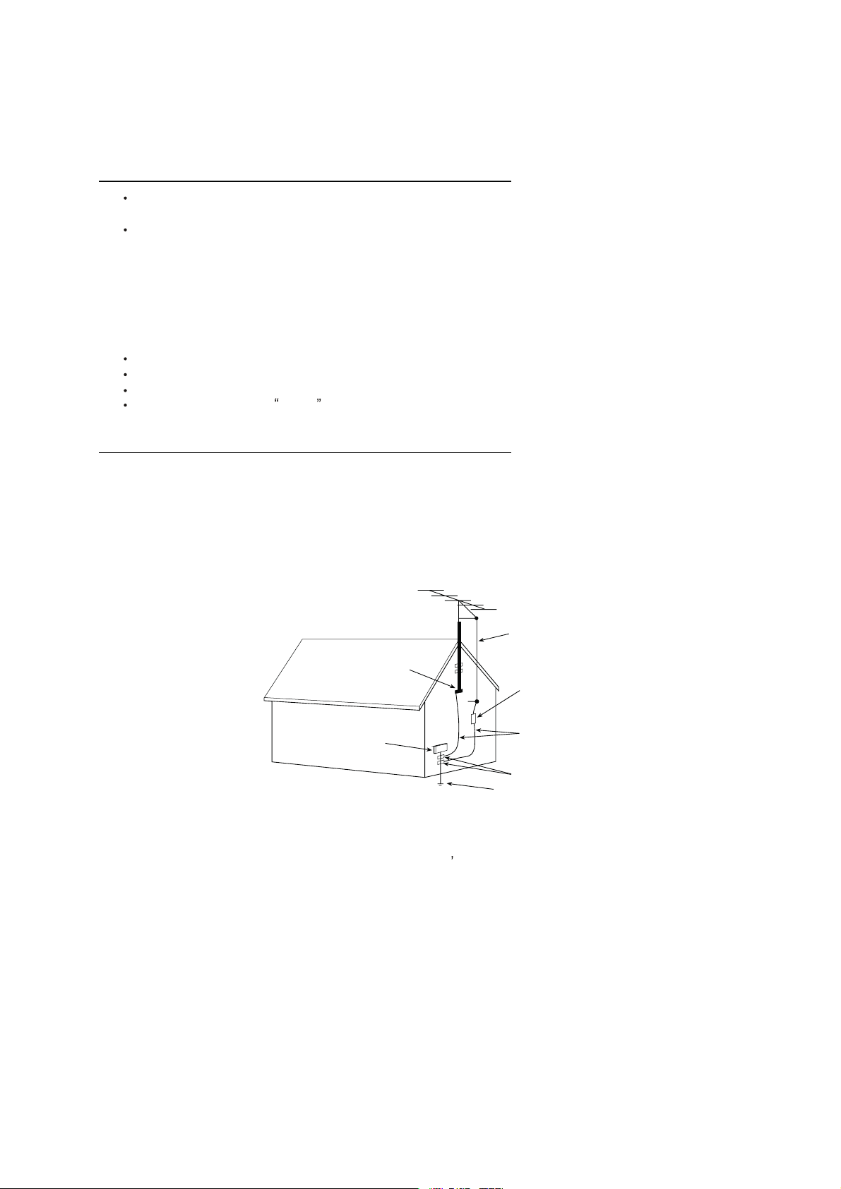
EXAMPLE OF ANTENNA GROUNDING AS PER NATIONAL ELECTRICAL CODE INSTR UCTIONS
EXAMPLE OF ANTENNA GROUNDING AS PER
NATIONAL ELECTRICAL CODE
ANTENNA
LEAD- IN WIRE
GROUND CLAMP
ELECTRIC SERVICE
EQUIPMENT
NEC-NATIONAL ELECTRICAL CODE
ANTENNA DISCHARGE
UNIT (NEC SECTION
810-20)
GROUNDING
CONDUCTORS
(NECSECTION 810-21)
GROUND CLAMPS
POWER SER VICE GROUNDING
ELECTRODE SYSTEM
(NEC ART 250. PART H)
15.2. Note to CATV system installer : (Only for the television set with CATV reception)
This reminder is provided to call the CATV system attention to Ar ticle 820-40 of the NEC that provides
installer s
guidelines for proper grounding and, in particular, specifies that the cable ground shall be connected to the grounding
system of the building, as close to the point of cable entry as practical.
16. An outside antenna system should not be located in the vicinity of overhead power lines or other electric lights or power
circuits, or where it can fall into such power lines or circuits. When installing an outside antenna system, extreme care
should be taken to keep from touching such power lines or circuits as contact with them might be fatal.
17. For added protection for this television set during a lightning storm, or when it is left unattended and unused for long
periods of time, unplug it from the wall outlet and disconnect the antenna. This will prevent damage due to lightning
and power-line surges.
4
4
Page 5

SCHNEIDER ELECTRONICS GMBH-GERMANY
OPERATION OF YOUR SET
18.
This television set should be operated only from the type of power source indicated on the marking label.If you are not
sure of the type of power supply at your home, consult your television dealer or local power company. For television
sets designed to operate from battery power, refer to the operating instructions.
19. If the television set does not operate normally by following the operating instructions, unplug this television set from the
wall outlet and refer servicing to qualified service personnel. Adjust only those controls that are covered in the operating
instructions as improper adjustment of other controls may result in damage and will often require extensive work by a
qualified technician to restore the television set to normal operation.
20. When going on a holiday : If your television set is to remain unused for a period of time, for instance, when you go on
a holiday, turn the television set and unplug the television set from the wall outlet.
off
IF THE SET DOES NOT OPERATE PROPERLY
21. If you are unable to restore normaloperation by followingthe detailedprocedurein youroperating instructions,
do not attempt any further adjustment. Unplug the set and call your dealer or service technician.
22. Whenever the television set is damaged or fails, or a distinct change in performance indicates a need for
service, unplug the set and have it checked by a professional service technician.
23. It is normal for some TV sets to make occasional snapping or popping sounds, particularly when being
turned on or off. If the snapping or popping is continuous or frequent, unplug the set and consult your
dealer or service technician.
FOR SERVICE AND MODIFICATION
24. Do not use attachments not recommendedby the television set manufacturer as they may cause hazards.
25. When replacement parts are required, be sure the service technician has used replacement parts specified
by the manufacturer that have the same characteristics as the original part. Unauthorized substitutions
may result in fire, electric shock, or other hazards.
26. Upon completion of any service or repairs to the tele vision set, ask the service technician to perform
routine safety checks to determine that the television is in safe operating condition.
5
5
Page 6
TCL Multimedia Technology Holdings Ltd.
R&D Center
Alignment Procedure
MS82CD-AP/LA Chassis
Version: 1.0
Release Date: 2013-04-23
PREPARED BY: HEXIAOPENG DATE: 2013-04-23
APPROVED BY: DATE:
Page 7
MS82CD-AP/LA Chassis Aliment procedure
2
Date
V1.0
2013-04-23
Chassis
Model
Content
1. General Description 3
2. Factory Menu 3
2.1 Way of accessing 3
2.2 Factory Menu 4
2.3 ADC calibration menu 5
2.4 White Balance adjustment 6
3. Design Menu 7
3.1 way of accessing 7
3.2 SHOP Menu 8
3.3 Other Menu 9
3.4 Service Menu 10
3.5 PARAM SETTING MENU 11
3.6 Hotel Menu 12
4. Steps of debugging 13
4.1 Device 13
4.2 steps of debugging 13
4.3 ADC calibration 13
4.4 White Balance adjustment 14
4.5 White Balance adjustment (automatically) 16
5. Chip list of software programming before SMT 16
6. Appendix 17
6.1 Software upgrading through USB 17
6.2 Check software version, release date and Project ID 18
6.3 FAQ 20
History Description of major changes Release
HD MS82CD-AP/LA L32E3020/L32E3000/L32E3010 etc.
PRELIMINARY INFORMATION ----- SUBJECT TO CHANGE
Page 8
MS82CD-AP/LA Chassis Aliment procedure
3
Factory Menu covers all indispensable functions during
When you wish to learn the product
1. General Description
MS82CD-AP is ou r latest design especially for LCDTV products selling in Asia
Pacific (AP) and Latin America (LA) market.. It features by its high integration,
easy debugging as well as convenience in terms of maintenance. Fa s t sof tware
upgrade through USB disk facilitates both manufacture and after-sale service.
Meantime, a variety of functions involved in Factory Main Menu can not only
bring benefits for production, but also satisfy various demands of customer.
Note: Factory Main Menu (FMM) is divided into Factory Menu, Design Menu, Servic e
Menu and Hotel Menu.
manufacture such as Whit e Bal a nce Adjustment, ADC C al ibr ati o n, USB Upgrading e.g.,
while the items under Design Menu is exclusively used by R&D engineer, anyone else
shouldn’t change the settings in the menu.
information like project ID, model name, chassis name, software version, release date,
you can access to Service Menu. In addition, in Hotel Menu, we also provide a great
deal of useful functions for specific applications in hotel.
2. Factory Menu
2.1 Accessing way:
a. In the first place, press Menu button of
remote
control, then select Contrast item of Picture
submenu. Finally, press 9, 7, 3, 5 consecutively.
b. When the FAC HOTKEY item of Factory Menu
is enabled (ON), press Return button of remote
control.
PRELIMINARY INFORMATION ----- SUBJECT TO CHANGE
Page 9
MS82CD-AP/LA Chassis Aliment procedure
4
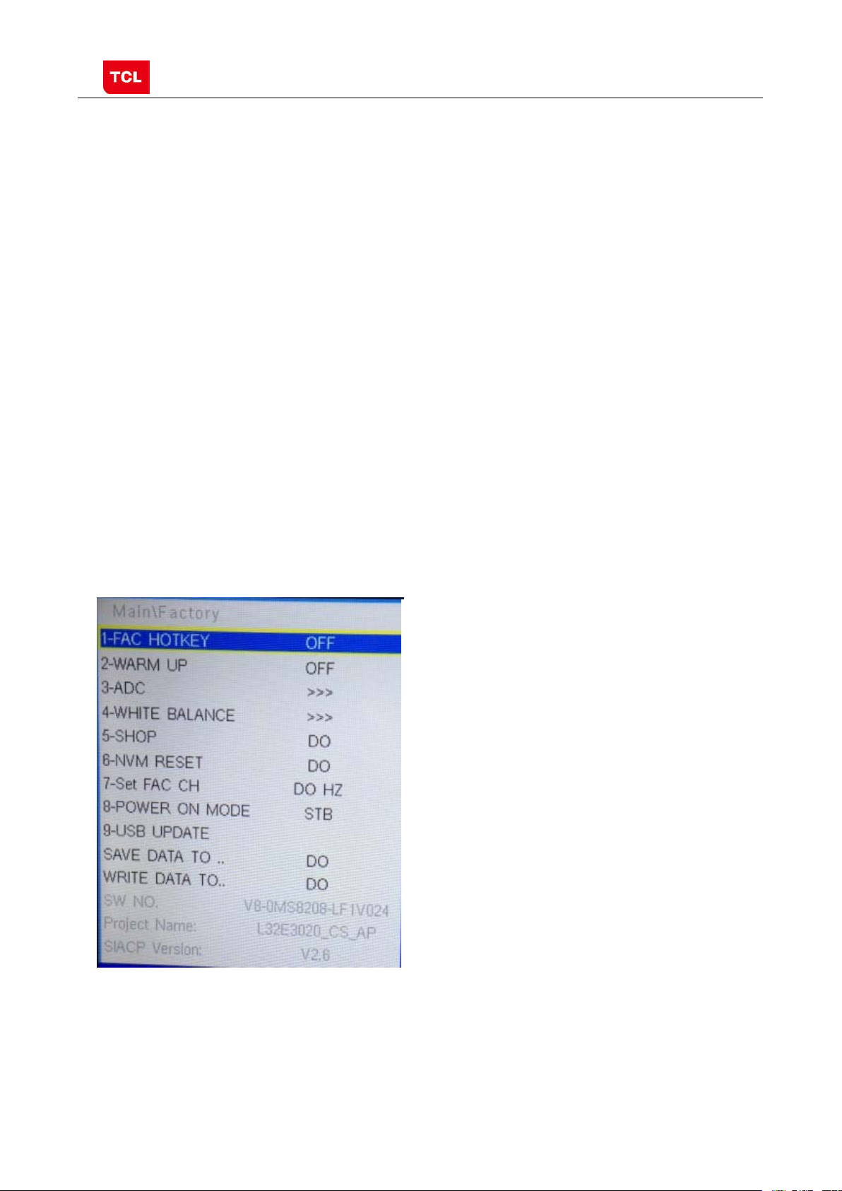
Factory Menu
The item must be disabled (OFF) after production
‘function’key to exit warm-up mode.
BALANCE
Factory Menu after executing the item.
remote control and wait until the disappearance of Factory Menu,
MS82S-LA
UPDATE
TO…
DATE TO…
Name
Version
2.2 Factory Menu
Name Default Description Status
FAC
HOTKEY
OFF Factory Menu shortcut button switch
OK
WARM-
UP
ADC >> ADC calibration ( see details below) OK
WHITE
SHOP
NVM RESET DO Restore default value except WB and ADC data. OK
SET FAC CH DO HZ Preset the channel table of factory. Option: HZ, WX, EGYPT-EL,
Power On
Mode
OFF OFF: Normal mode. Display blue screen when no signal. Turn to
automatically standby mode if keep the signal unavailable over
15 minutes.
ON: Aging mode. Display snow dot when no signal. The set will not
turn to standby even if the unavailability of signal;press
>> White Balance Adjustment ( see details below) OK
DO It is crucial that the function is executed after production aim to clear
information of production process, ensure user cannot access to
ALGERIA e.g. To preset the channel table of certain factory, firstly,
choose the corresponding factory name, then press OK button of
STB ON: the set will power on after switching on power.
STB: the set will remain standby status after switching on power.
Last: the set will turn to the status in which it lies when last switching
off.
If without requirement from certain customer,
by default, the Setting should be Last for MS82S-AP and STB for
OK
OK
OK
OK
USB
Upgrade software. Please see details below. OK
SAVE DATE
WRITE
DO
DO
Save the settings of system information to USB
Write the settings of system information to TV from USB
SW NO. OFF Version information of Main Software OK
Project
SIACP
Product model OK
Serial port remote control protocol OK
PRELIMINARY INFORMATION ----- SUBJECT TO CHANGE
OK
OK
Page 10
MS82CD-AP/LA Chassis Aliment procedure
5
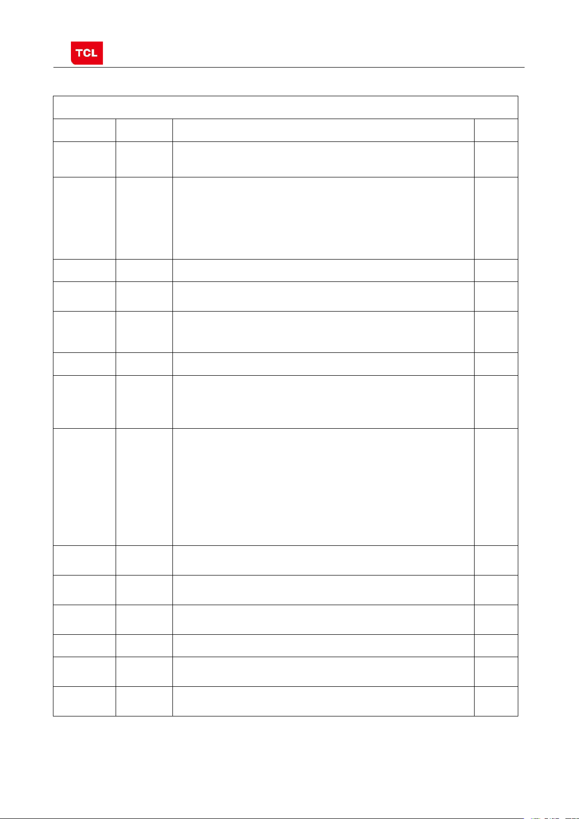
Only YPBPR and RGB are available.
is displayed.
Otherwise, It is a failing calibration (“FAIL” is displayed).
Otherwise FAIL will be displayed
2.3 ADC calibration menu
ADC Menu
Press the button in remote control to select certain
item and to change the value of ADC data or start
ADC calibration.
Notes:
1. Only YPBPR and RGB source should be calibrated.
ADC Calibration menu
Name Default Description Status
SOURCE RGB Select the source you intend to ADC Calibrate.
OK
R GAIN 4096 Gain of R channel ( cannot be changed after auto calibration) OK
G GAIN 4096 Gain of G channel ( cannot be changed after auto calibration) OK
B GAIN 4096 Gain of B channel ( cannot be changed after auto calibration) OK
R OFFSET 0 Offset of R cha n n el ( cannot be changed after auto calibration) OK
B OFFSET 0 Offset of B cha n n el ( cannot be changed after auto calibration) OK
G OFFSET 0 Offset of G channel ( cannot be changed after auto calibration) OK
AUTO ADC DO Select and execute the item, ADC Calibration starts. It indicates
a successful calibration if prompt “OK”
OK
ADC
STATUS
OK Show the A DC status of YPbPr/RGB Channel. SUCCESS will be
display if YPbPr/RGB Channel has been correctly calibrated.
OK
PRELIMINARY INFORMATION ----- SUBJECT TO CHANGE
Page 11
MS82CD-AP/LA Chassis Aliment procedure
6
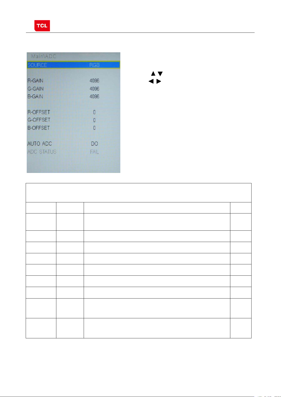
Only HDMI1, AV1, YPBPR, PC and should be adjusted.
source.
be executed.
2.4 White Balance Adjustment menu
White Balance menu
Press the button in remote control to select
certain item and
to adjust White Balance
White Balance Adjustment menu
Name Default Description Status
Source PC Select the source you intend to apply WB adjustment.
OK
COLOR
TEMPERATURE
Normal Select color temperature you intend to adjust Three groups of
color temperature: Normal, Warm, Cool are av ailable for each
OK
R GAIN
G GAIN
B GAIN
R OFFSET
Gain of R channel ( cannot be changed after auto calibration) OK
Gain of G channel ( cannot be changed after auto calibration) OK
Gain of B channel ( cannot be changed after auto calibration) OK
Offset of R channel ( cannot be changed after auto calibration) OK
G OFFSET
Offset of G channel ( cannot be changed after auto calibration) OK
B OFFSET
Offset of B channel ( cannot be changed after auto calibration) OK
WB INIT
ADC STATUS
PRELIMINARY INFORMATION ----- SUBJECT TO CHANGE
DO
OK
White Balance Initalization. Bef or e WB adjustment, this item should
ADC status indicator
OK
OK
Page 12
MS82CD-AP/LA Chassis Aliment procedure
7
Main Menu
The item must be disabled (OFF) after production
details below.
engineer to solve problems. It is exclusively used by R&D.
reference to SERVICE MENU submenu
, sharpness,
. Please reference to
PARAM SETTING submenu.
(ON).
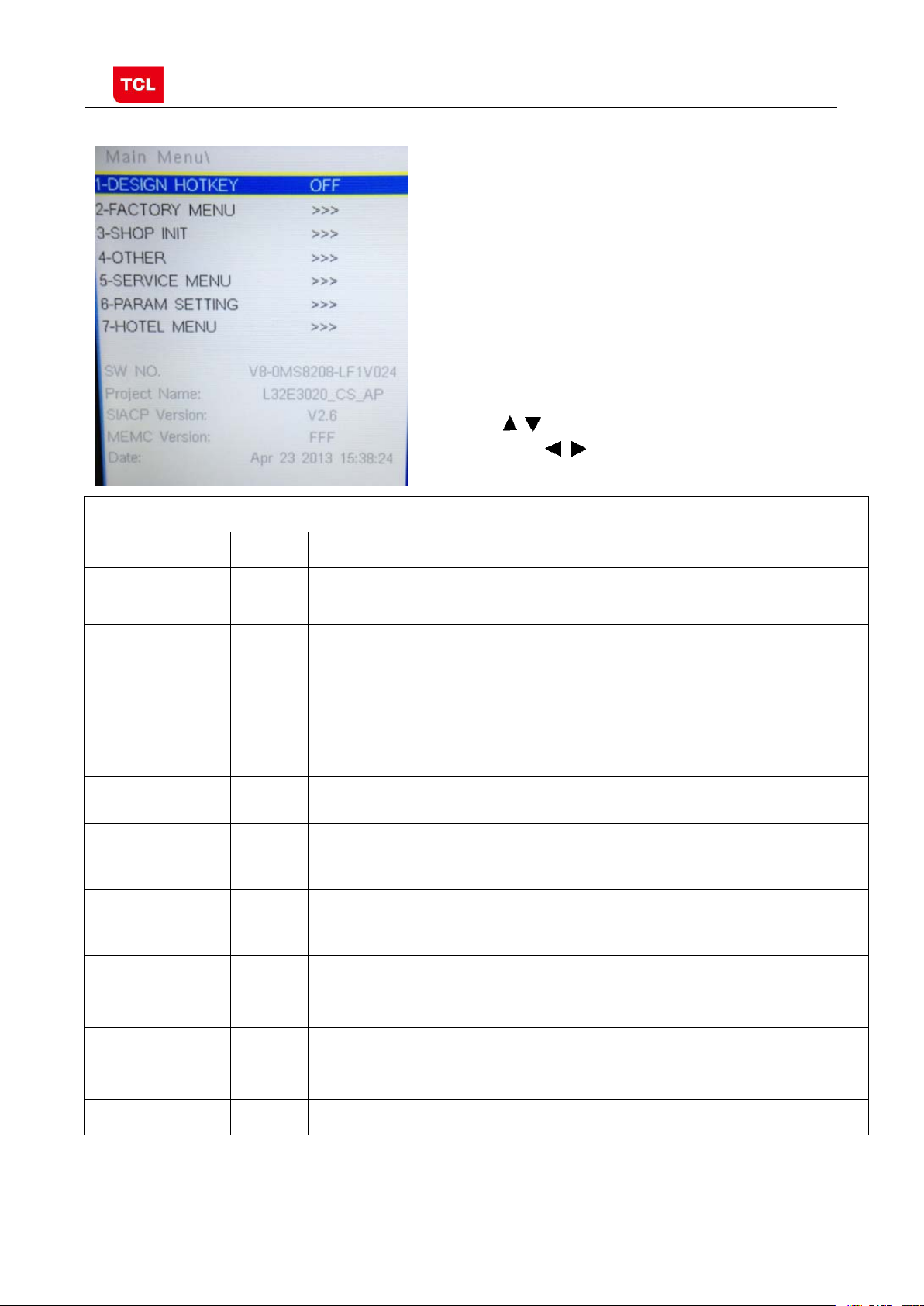
3 Factory Main Menu
3.1 Accessing way:
1. In the first place, press Menu button of
remote control, then s elect Contrast item
of Picture submenu. Finally, press 1, 9, 5, 0
consecutively.
2. When the DESIGN HOTKEY item of Design
Menu is enabled (ON), press Return button of
remote control.
Press the button in remote control to select
certain item and to toggle among or execute the
available options.
Name Default Description Status
DESIGN
HOTKEY
OFF Design Menu shortcut button switch
OK
FACTOR Y MENU
SHOP
INIT
OTHER
SERVICE MENU
PARAM
SETTING
HOTEL MENU
SW NO.
Project Name
SIACP Version
MEMC Version
>>> Access to Factory Menu OK
>>> Contain many options which can be chosen according to the
requirements of customers as default settings when leave factory. See
>>> The item includes a number of funct i ons offering convenience for R&D
>>>
>>> Include volume, brightness, contrast, saturation, hue
>>> Include special functions which bring benefits to hotel management.
Version information of Main Software OK
Product model OK
Serial port remote control protocol OK
FFF Version information of MEMC NG
Provide many useful information for aftersale service。Please
backlight, volume, overscan Adjustment etc
The item is accessible only when HOTEL ENABLE item is enabled
OK
OK
OK
OK
OK
Date:
Release date, time
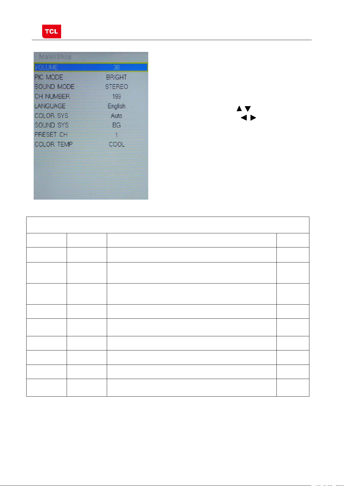
3.2 SHOP MENU
PRELIMINARY INFORMATION ----- SUBJECT TO CHANGE
OK
Page 13
MS82CD-AP/LA Chassis Aliment procedure
8
BRIGHT, SOFT, PERSONAL,STANDARD
STAREO MISIC, MOVIE, NEWS
Thai, Portuguese, Mongolian, LA: English, Portuguese, Spanish
TEMP
Contain many options which can be chosen according
to the requirements of customers as default settings
when leave factory. Press the
control to select certain item and to toggle
among the available options..
button in remote
SHOP MENU
Name Default Description Status
VOLUME 30 Volume setting, 0~100 adjustable OK
PIC MODE STANDARD Picture mode. Options:
SOUND
MODE
STEREO Sound effects. Options:
CH NUMBER 199 Maximum number of accessible channel OK
LANGUAGE ENGLISH AP: English, French, Vietnamese, Russian, Arabic, Farsi, Hebrew,
COLOR SYS Auto TV Color system:PAL,NTSC,SECAM. OK
SOUND SYS BG TV Sound system:BG,I,DK,M OK
PRESET CH 1 Preset channel. 0~199 optional OK
OK
OK
OK
COLOR
NORMAL Color temperature. Option: NORMAL, WARM, COOL OK
3.3 Other Menu
PRELIMINARY INFORMATION ----- SUBJECT TO CHANGE
Page 14

MS82CD-AP/LA Chassis Aliment procedure
9
ADJUST
Exclusively used by R&D.
Exclusively used by R&D.
Exclusively used by R&D.
Exclusively used by R&D.
Exclusively used by R&D
Exclusively used by R&D
LA products have no this menu.
Press the button in remote control to select
certain item and to toggle among the available
options..
Other Menu
Name Default Description Status
VIF1 >>> Exclusively used by R&D. NG
VIF2 >>> Exclusively used by R&D. NG
VIF3 >>> Exclusively used by R&D. NG
QMAP
SSC >>> Spectrum Spread Control.
DBC
ENABLE
BP Parameter of DBC
CP Parameter of DBC
DBC MODE ON DBC Mode. Exclusively used by R&D. NG
MIU0 DQS0 11 Manually adjust DQS1 phase of DDR2
>>> Exclusively used by R&D. NG
OK
OFF Dynamic Backlight Enable
NG
NG
NG
NG
MIU1 DQS1 11 Manually adjust DQS1 phase of DDR1
TTX ON ON: enable teletext OFF: Disable teletext
HPF High pass filter for audio EQ OK
PRELIMINARY INFORMATION ----- SUBJECT TO CHANGE
NG
NG
Page 15

MS82CD-AP/LA Chassis Aliment procedure
10
Version
ENABLE
CODE
Off: not display
3.4 SERVICE MENU
Press the button in remote control to select certain
item and to toggle among the available options..
Name Default Description Status
SERVICE MENU (Product Info)
SW NO. Software virtual code of Main Software OK
DATE Release date, time OK
Project Name Model of product OK
SIACP
Serial port remote control protocol
OK
Chassis MS82 Chassis name OK
PANEL NAME Panel code OK
PROJECT ID >>> Select project parameters through project ID. OK
USB UPDATE >>> USB upgrade. OK
HOTEL
OFF Switch of Hotel Menu. OK
ERROR
OFF OK
TCL_LOGO ON Display TCL Logo or not. On : display,
LOGO_LIGHT ON NG
TCL_SHOW ON DEMO function ON/OFF OK
PRELIMINARY INFORMATION ----- SUBJECT TO CHANGE
OK
Page 16

MS82CD-AP/LA Chassis Aliment procedure
11
djustment. Exclusively used by
R&D.
used by R&D.
used by R&D.
used by R&D.
used by R&D.
3.5 PARAM SETTING MENU
Press the button in remote control to select certain item
and
to enter menu.
Name Default Description Status
Brightness Curve >>> Brightness curve. Exclusively used by R&D. OK
Contrast Curve >>> Contrast curve. Exclusively used by R&D. OK
PARAM SETTING MENU (Setting menu)
Saturation Curve >>> Saturation curves. Exclusively used by R&D. OK
Hue Curve >>> Hue Curve Exclusively used by R&D. OK
Volume Curve >>> Volume curve. Exclusively used by R&D. OK
Backlight Curve >>> Backlight curve. Exclusively used by R&D. OK
OverScan >>> Overscan a
OK
LVDS Step 10
For LVDS adjust,Exclusively used by R&D.
OK
TconGamma P1… >>> For T_CON Gamma adjustment, Exclusively
NG
TconGamma P2… >>> For T_CON Gamma adjustment, Exclusively
LSRationMIN(OSD) 52 For Lightsensor adjustmeng, Exclusively
LStmax(PRINT) CA For Lightsensor adjustmeng, Exclusively
PRELIMINARY INFORMATION ----- SUBJECT TO CHANGE
NG
NG
NG
Page 17

MS82CD-AP/LA Chassis Aliment procedure
12
LOGO
When it is ON, these items are selectable.
MODE
VOL.
SIGNAL
CHANNEL
TO
DATA TO
3.6 HOTEL MENU
Press the button in remote control to select
certain item and
to enter submenu.
Name Default Description Status
POWER
CH LOCK ON Channel scan lock. OK
MAX VOL 100 Max volume OK
AUTO SET OFF The switch of PIC, SOUND etc.
PIC MODE Standard Picture mode. OK
SOUND
POWER
POWER
ON LOGO select OK
STEREO Sound mode OK
50 Default volume when power on OK
TV Default signal source when power on OK
HOTEL MENU
OK
POWER
0 Default channel no. when power on OK
KEY LOCK OFF Lock the keys. OK
SAVE DATA
WRITE
PRELIMINARY INFORMATION ----- SUBJECT TO CHANGE
DO Save the hotel settings of Hotel Menu to USB OK
DO Copy the hotel settings of Hotel Menu from USB OK
Page 18

MS82CD-AP/LA Chassis Aliment procedure
13
4. The steps of debugging
4.1 Device
4.2 steps of debugging:
4.3 ADC Calibration
Color Analyzer CA-210. Video Pattern Generator Chroma2329. Color TV Pattern
Generator PM5418, VGA cable, AV cable(RCA),YPBPR (RCA) cable.
。
Chroma2329 Fluke5418 CA-210
According to the requirement of order, we suggest take the below steps to finish
the appropriate settings.
A enter the Factory Menu, enable FAC HOTKEY
B Check the version of software, release date displayed a t the bottom of Factory
Menu. If the information is correct, you can ignore step C and D.
C Enter Factory Main Menu, choose SERVICE MENU->PROJECT ID, choose
corresponding Project I D number of the product (Please refer to the descrip tion in
BOM about Project ID number).
D return to Factory Menu, check the Product model.
E choose Factory Menu-> NVM RESET and press and wait until prompt OK
appears.
F restart the set
G according to the requirement of order, set the items of Shop Menu and Hotel
Menu etc.
H After aging under normal temperature, calibrate ADC and adjust white balance.
I choose Factory Menu-> SHOP INIT and press button of remote control to
initialize the set.
Note: after step I (execute SHOP INIT), Hotel Menu will be disabled by default.
Therefore, if order requires hotel function, it is necessary to enable hotel function by
set Factory Main Menu-> Service Menu->HOTEL ENABLE to ON.
Ⅰ.signal and generator
VGA: Chroma23 29 Pattern42, Timing 14(1 024x768@60Hz 5 MOSAIC)
YPBPR: Chroma2329 Pattern103, Timing 79(100% Color Bar, 720p)
PRELIMINARY INFORMATION ----- SUBJECT TO CHANGE
Page 19
MS82CD-AP/LA Chassis Aliment procedure
14
5 MOSAIC 100% Color Bar
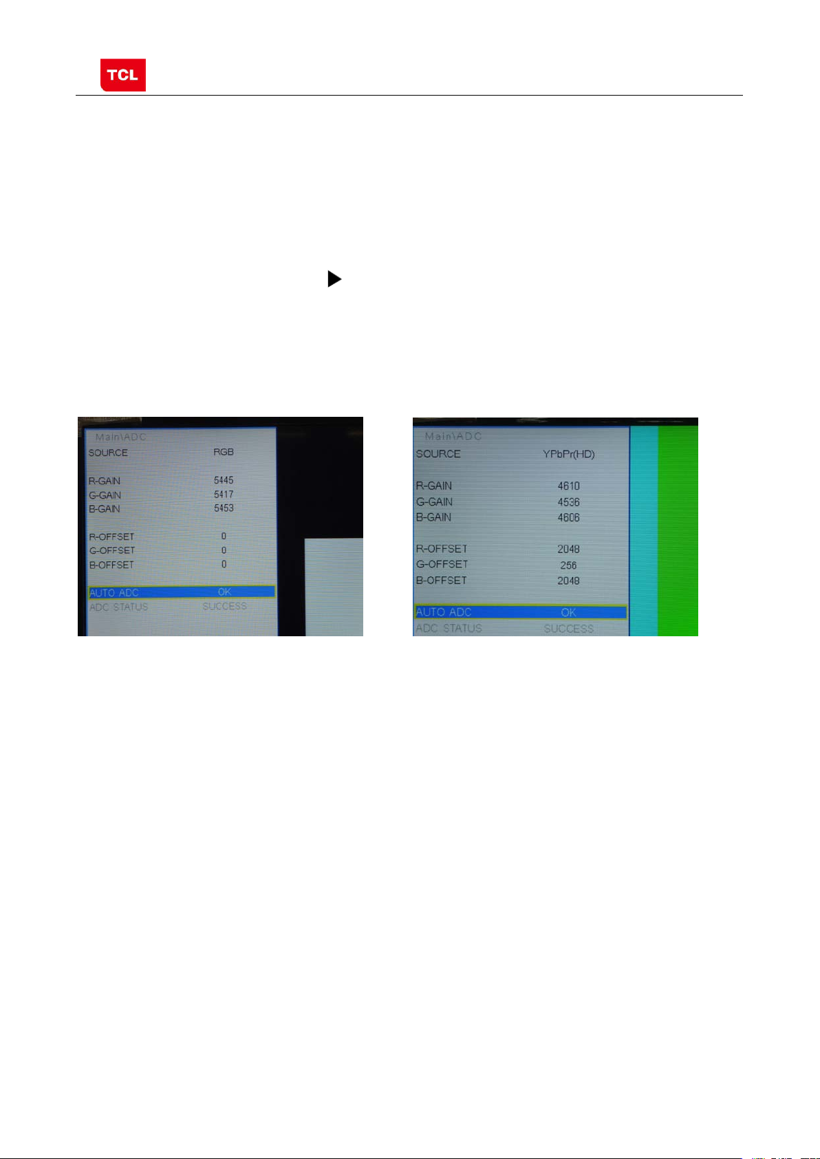
Ⅱ.steps of debug:
1) Access to the Factory menu->ADC
2) Select PC source
3) Select AUTO ADC,Press button in your remote control to calibrate the
ADC automatically.
4) Select YPBPR source
5) Repeat step 3.
6) When the OK appears the calibration has been finished successfully.
VGA calibration YPBPR calibration
4.4 White Balance adjustment (Manual)
Before adjustment, you must ensure Color Analyzer has been calibrated. Only AV1,
YPBPR, PC , HDMI 1 need to be adjusted. It is necessary to adjustment HDMI 1 firstly.
a. signal and generator
The pattern of the signal should be used are White (Chrom a2329 pattern113) and
Grey (pattern 114).The format of signal are respectively 720p for HDMI1
(Chroma2329 Timing 69), NTSC for AV1 (Chroma2329 Timi ng 37),1024×768@60Hz
(Chroma2329 Tim i ng 14) for PC and 720p (Chroma2329 Timing 79)for YPBPR
b. steps of adjustment
1) enter the factory menu->WHITE BALANCE, sel e ct source HDMI 1 and COLORTEMP
normal.
2) input grey signal in 720p format
3) change R OFFSET and B OFFSET to make sure the value of color coordination
equ al to the value required by enterprise standard (x, y).
PRELIMINARY INFORMATION ----- SUBJECT TO CHANGE
Page 20

MS82CD-AP/LA Chassis Aliment procedure
15
HDMI White Balance adjustment
4) input white signal in 720p format
5) change R Gain and B Gain to make sure the value of color coordination equal to
(x, y).
6) repeat step 2~5 until both of the value of color coordination of white and grey
equ al to (x, y).
In addition to select COLORTEMP COOL/WARM, the adjustment method of COOL
and WARM color temperature is same with that of NORMAL. The color coordination
we recommend is as follows:
Device:CA-210; Accuracy:±0.015
Model WARM NORMAL COOL
L32E3020
X 0.268 0.282 0.252
Y 0.279 0.288 0.260
PRELIMINARY INFORMATION ----- SUBJECT TO CHANGE
Page 21

MS82CD-AP/LA Chassis Aliment procedure
16
description
4.5 ADC Calibration and White Balance Adjustment (automatic)
The process of adjusting ADC and White Bal ance automatically is out of the range
of this file. Please refer to the relevant technical file of HuiZhou factory of TCL.
5. Chip list of software programming before SM T
Following chips must be programmed before SMT by ALL-11 or other tools.
Position Chip type Chip name Part number Software
1 U503 Flash EN25Q32B 13-EN25Q3-2BBEO main software SO-8
2 U702 E2PROM M24C32MN 13-M24C32-MNB Tcon software SO-8
Note:
1) The software for U503 and U702 can be program using ISP tool.
2) Every set has its unique HDCP key which is purchased from suppliers or HDCP
certification author i ty. Please check HDCP function in the process of production.
3) Once in a while, the software of main board may be upgraded. Please pay attention to
use the latest software before production.
Decal
PRELIMINARY INFORMATION ----- SUBJECT TO CHANGE
Page 22

MS82CD-AP/LA Chassis Aliment procedure
17
Upgrade Main Software
Appendix:
1. Software upgrade through USB disk
1) Please ensure the software you are using has a correct file name
TCL_MS82_UPDATE.bin, then copy it to the root directory of a US B disk.
2) Insert the USB disk to the USB socket of the set for which you are
going to upgrade program.
3) Enter the Factory Menu (you can choose either a or b way below)
a. In the first place, press Menu button of remote
control, then select Contrast item of Picture
submenu. Finally, press 9, 7, 3, 5 consecutively.
b. When the Factory hotkey item of Factory Menu
is enabled (ON), press Return button of remote
control.
4) select USB UPDATE, press buttonof re mote control, a pop menu
will appear prompting whether start upgradeor not. Press Yes to start upgrade,
press No to canel. Please wait patiently until the set restart automatically after
upgrade. Do not cut off the power supply during the process.
PRELIMINARY INFORMATION ----- SUBJECT TO CHANGE
Page 23

MS82CD-AP/LA Chassis Aliment procedure
18
2. Check software version, release date and Project ID
After upgrading, sometimes you may not certain whether the new software has
been successfully updated or not. In this case, you can check the software version
and release date in Factory Main Menu to make sure the success of upgrading.
In addition, for the convenience of software management, many models of same
chassis may share a same software, but are allocated with different Project ID.
In another words, every model has its unique Project ID. Obviously, Both software
version and Project ID are highly critical to ensure the set work properly. Therefore,
after upgrading software,we suggest you check these information by following
method.
1) Enter the Factory Main Menu(you can choose either a or b way below
a In the first place, press Menu button of re mote control, then select Contrast item
of Picture submenu. Finally, press 1, 9 5, 0 consecutively.
b. When the DESIGN HOTKEY item of Factory Main Menu is enabled (ON), press
Return button of remote co ntrol.
2) Check the version of software, release date displayed at the bottom of Factory
Main Menu. If the information is correct, you can ignore step C and D.
3) choose SERVICE MENU->PROJECT ID, choose corresponding Project ID number of
the product (Please refer to the description in BOM about Project ID number).
4) choose Factory Menu and press OK button of the remote. Next, select NVM RESET
and press and wait until prompt OK appears.
5) choose SHOP INIT and press button of remote control to initialize the set.
Note: after step I (execute SHOP INIT), Hotel Menu will be disabled by default.
Therefore, if order requires hotel function, it is necessary to enable hotel function by
set Factory Main Menu-> Service Menu->HOTEL ENABLE to ON.
6) restart the set.
PRELIMINARY INFORMATION ----- SUBJECT TO CHANGE
Page 24

MS82CD-AP/LA Chassis Aliment procedure
19
Check product information
Change project ID
Product
Information
Remote Contr o l name
Power Supply name
Audio Channe l numb er
PRELIMINARY INFORMATION ----- SUBJECT TO CHANGE
Page 25

MS82CD-AP/LA Chassis Aliment procedure
20
3. FAQ
1) Why there is no picture after upgrading software or changing project ID?
It may be caused by fault of project ID. You can try below method to fix
the problem.
a. If the resolution of the panel of your set is 1366×768(HD panel), you can press
Menu, and 4976 of remote control in series after turning on.
b. If the resolution of the panel of your set is 1920×1080(FHD panel), you
can press Menu, and 4973 in series after turning on.
c. I f you can see the picture at this time, please recheck the project ID again. If
the project ID is still wrong, correct it reference to above description.
PRELIMINARY INFORMATION ----- SUBJECT TO CHANGE
Page 26

8 7 6 5
4 3 2 1
VIN
3
GND
C106
0.1U
GND
U101
AS1117-1.8
VIN
3
4
4
OUT
2
VIN
4
OUT
3
4
2
GND/ADJ
1
C140
0.1U
U102
AS1117-2.5
4
4
GND/ADJ
OUT
1
2
GND/ADJ
1
C138
0.1U
C139
0.1U
3V3_NORMAL
T
C102
100U
16V
2V5
T
1V8_DDR
T
C160
100U
16V
3V3_NORMAL
2V5
C162
100U
16V
1V8
12V
NC/
12V
C115
220U
16V
GND
C103
0.1U
C126
0.1U
C119
0.1U
C125
10U
D102
LL4148
8
7
VIN
5
BOOTFBUGATE
RT8110B
U105
f=400KHz
VCC
LGATE
GNDPHASE
F
C124
2U2
1
GND
2
36
GND
4
GND
D13N03LT
G2
4
S2
3
G1
2
S1
1
Q110
D2B
D2A
D1B
D1A
R108
Z102
T
GND
3K3
R109
560R
R151
47R
C128
820P
@max 5A
5V
E
L100
R103R104
10R
C123
1000P
10UH
C101
10U
GND
C111
10U
C104
10U
C127
0.1U
C114
220U
16V
VREF=0.8V
5
6
7
8
10R
GND
D
3V3_STB
F
POWER_ON
(5)
BL_ON
T
E
BL_ON_OUT
R125
10K
R126
330R
C145
0.01U
GND
D
R127
DIM
BL_ON
P_ON
3V3_STB
GND
3K3
R128
330R
1 2
3
5
7
9
11
13
P105
4
6
8
10
12
14
C132
0.1U
P_ON
T
C146
0.01U
BL_ON
P_ON
3V3_STB
GND
DIM
GND
GND1
T
12V
P_ON
12V
T T
12V
0.01U
GND
DIM_PWM
C148
GND
T
R124
220R
DIM_OUT
3V3STB
T
C150
GND
0.1U
(5)
AS1117-3.3
5V
U103
C141
0.1U
C118
0.1U
GND
3V3_STB
T
GND
C155
0.1U
3V3_STB
IR
T
C154
1000P
R132
F100
T
47K
R131
220R
R129
2
1K
D104
1000P
0BAV99NC/
3
C159
1
GND
close to P100
R133
22K
C158
0.1U
3V3_STB
IR_IN
LED_OUT
KEY_IN
R102
4K7
GND
U104
13 8
15
16
14 7
BSRT
EN
PGCOMP
1
(vin=2.95V~5.8V)
5V
U106
1
FLG
2
GND
RT9711
VOUT
VINEN/EN#
5
43
5V
C105
1U
GND
10U
GND
USB_5V
C110
C161
10U
C108
0.1U
GND
2
3
4
VINA
VIN1
GND1
GND2
VIN2
AGND
5
R110
20K
C130
3300P
G5193
FB
6
GND
R152
150K
GND
LX3
LX2
LX1
SS
C116
0.1U
12
11
10
9
C121
0.01U
NC/
L103
MINI1UH
L102
1UH
GND
C120
0.1U
22U
C113
GND
VREF=0.803V
C107
22U
VDDC
T
GND
R106
5K1
R105
6K2
R140
3K3
VDDC
C
B
LED
1
2
3
GND
C
4
5
P100
close to P100
B
KEY
C151
0.1U
GND
KEY
C117
0.1U
T
GND
PANEL_VCC
T
5V
A
R116
0R
CLOSE TO FFC SOCKET
PANEL_VCC
THIS DRAWING CANNOT BE COMMUNICATED TO UNAUTHORIZED PERSONS COPIED UNLES S PERMITTED IN WRITING
SBU :
TCLNO:
Index-Lab
DATE
DESCRIPTION Last modifNAME
Last saved :
5
4678
.............
TCL Thomson Electronics Singapore Pte. Ltd.
8 Jurong Hall Road #28-01/06
The JTC Summit SINGAPORE 609434
DESIGNATION
DRAWN
DESIGNATION
3 2 1
ON:
BY:
Tel (65) 63092900 Fax (65) 63092999
CHECKED
PAGE:
ON:
BY:
OF :
A
FORMAT DIN A2
Page 27

8 7 6 5
TDA18273+CAN_TUNER_ONBOARD_COMP SCH, VER1.0 2012-7-25
4 3 2 1
F
TU_3V3
E
D
RT2
0R
TUNER_VCC
CT18
10U
TUN1
S1
GND1
GND2
GND3
GND4
GND5
GND6
CT19
47N
1
2
3
4
5
6
7
CT20
47N
GND
CT21
47N
FT1
CT22
47N
GND
CT24
CT23
47N
100P
GND
CT1 CT2
120P
LT1
330NH 140MA
Caution:
TU_3V3 must be from LDO
120P
CT3
150P
LT2
220NH 120MA
GND
1
3
0BAV99
DT1
TUNER_VCC
CT4
82P
2
GND
RT1
0R
GND
CT33
22P
1
2
3
4
5
6
7
8
9
10
CT5
0.22U
VCC1-RF
RFIN
NC1
NC2
GND1
AS_XTSEL
GND2
TEST1
TEST2
GND3
CT34
22P
GND
CAPRFAGC
LT4
LT3
2.4NH
2.2NH
38
36
37
39
40
RFAGC_SENSE
UHFSUPPLY
UHFLOW
UHFHIGH
TDA18273HN
TDA18273HN
XTALN
XTALP
GND4
SDA
SCL
111213141516171819
TUNER_VCC
LT5
8.2NH
100NH
TUNER_VCC
CT6 0.1U
32
33
34
35
VCC2-RF
VHFHIGH
VHFSENSE
VHFLOW
VHFSUPPLY
UT1
VTUNE
GND5
CAPREGVCO
VCC-SYNTH
6.8N
0.1U
CT14
CT15
GND
LT6
31
VSYNC
VIFAGC
VCC-IF
GND7
GND6
XTOUT2
XTOUT1
CP
20
CT12
IRQ
IFP
IFN
2.7N
GND
CT7
6.8N
30
29
28
27
26
25
24
23
22
21
TUNER_VCC
0.1U
0.1U
T
Z1
RT6
430R
CT10
CT11
GND
CT8
10P
CT13
0.22U
GND
CT9
10P
RT8
0R
0R
RT9
RT7
1K
VIF+
VIF-
F
E
D
33R
33R
RT16
RT15
TU_3V3
C
ANT
3V3
SCL
SDA
GND
XOUT
IF_N
IF_P
IF_AGC
TUN2
NC/
B
1
TU_3V3
2
3
4
5
6
7
8
9
TU_3V3
T
T
GND
GND
CT37
NC/
22P
NC/
CT32
NC/
CT30
NC/
10U
IF- IF+
GND GND
RT14
1K
6.8N
4K7
RT10
GND
NC/
RT12
NC/
RT13
NC/
CT28
22P
33R
33R
GND
NC/
CT38
22P
NC/
CT29
22P
TT
4K7
RT11
GND
T_SCL
T T
T_SDA
CT16
30P
XT16M
16M
CT17
30P
IFAGC
T
TUNER_SCL
TUNER_SDA
IF_AGC
0.047U
C225
R200
10K
RF_AGC
TU_3V3
R210
10K
5V
RF_AGC
3V3_NORMAL
4
4
GND/ADJ
C203
0.1U
VIN
OUT
3
2
1
GND
C200
220U
16V
TU_3V3
T
GNDGND
U200
AZ1117
C233
10U 0.1U
L201
NC/
C204
120R
C
300mA
TU_3V3
B
GND
A
THIS DRAWING CANNOT BE COMMUNICATED TO UNAUTHORIZED PERSONS COPIED UNLES S PERMITTED IN WRITING
GND
SBU :
TCLNO:
Index-Lab
DATE
DESCRIPTION Last modifNAME
Last saved :
5
4678
.............
TCL Thomson Electronics Singapore Pte. Ltd.
8 Jurong Hall Road #28-01/06
The JTC Summit SINGAPORE 609434
DESIGNATION
DRAWN
DESIGNATION
3 2 1
ON:
BY:
Tel (65) 63092900 Fax (65) 63092999
CHECKED
PAGE:
ON:
BY:
OF :
A
FORMAT DIN A2
Page 28

8 7 6 5 4 3 2 1
AV IN 1
CLOSE TO SOC
AV1_V
T
R307
12K
560P
C300
R300
100R
12K
R308
C301
F
E
GND6
AV1_V
AV1_L
T
AV1_L
AV1_R
T
AV1_R
T
F4
F6
F5
R301
10K
R302
10K
R306
75R
GND
560P
C325
0.047U
C326
2U2
C327
2U2
AV1_V_IN
AV1_L_IN
AV1_R_IN
AV OUT
YPBPR_AV2_IN
(5)
(5)
(5)
HD_R
HD_L
GND
R303
10K
R304
10K
GND
R318
12K
C302
560P
R322
C303
560P
12K
CLOSE TO SOC
C328
2U2
C329
2U2
HD1_R_IN
HD1_L_IN
(5)
(5)
AVOUT1_V
GND
R315
75R
C315
NC/
BT3906
1U
Q302
E
C
BT3904
220R
B
R314
R320
150R
Q301
5V
C
E
R319
10R
R313
470R
C311
NC/
F
R321
8K2
B
R343
NC/
22P
15K
AVOUT1_V_OUT
1K
R312
E
CLOSE TO SOC
D
P301
WHITE
WHITE
RED
RED
6
5
4
3
2
1
HD_L
HD_R
T
T
F300
F304
F305
AV1_L
HD_L
F306
AV1_R
HD_R
SPDIF
R325
120R
C313
33P
GND
C
GND
USB
GND5
T T
USB2_DP
USB2_DM
T
USB_5V1
T
USB_5V
B
GND
P303
VCC
D-
D+
1
2
3
4
F302
F301
C307
0.1U
GND
C306
NC/
220U
16V
R338
2R2
2R2
R339
USB2_D-_IN
USB2_D-_IN
USB2_D+_IN
USB2_D+_IN
(5)
(5)
A
THIS DRAWING CANNOT BE COMMUNICATED TO UNAUTHORIZED PERSONS COPIED UNLES S PERMITTED IN WRITING
R323
220R
C312
0.1U
...
...
...
...
SPDIF_OUT
T
HD_Y/AV2_IN
GND
DD-MM
DD-MM
DD-MM
DD-MM
DATE DESCRIPTION Last modifNAMEIndex-Lab
Last saved :
GND9
F7
F3
HD_PR
75R
HD_PB
75R
R328
75R
R333
...
...
...
...
(5)
R324
F8
...
...
...
...
9-13-2012_9:41
CLOSE TO SOC
R305
47R
R309
47R
R310
47R
10R
R311
45678
0.047U
C333
1000P
C330
0.047U
C331
C332
0.047U
GND
D
AVOUT1_V
T
T
HD_Y/AV2_IN
HD_PB
T
HD_PR
GND
AVOUT1_V
SPDIF
T
SPDIF
HD_PB
T
AV1_V
HD_PR
C
HD1_PR_IN
HD1_PB_IN
HD1_Y_IN+
HD1_SOG_IN
(5)
(5)
(5)
(5)
YELLOW
GREEN
BLACK
BLUE
YELLOW
RED
HD_Y/AV2_IN
P300
9
8
7
6
5
4
3
2
1
B
...
...
...
...
SBU :
TCLNO:
.............
DESIGNATION
...........
ADDRESS1
ADDRESS2
ADDRESS3
TELEPHONE
DRAWN
ON:
BY:
TCL
CHECKED
DD-MM-YY
ON:
BY:
......
PAGE:
OF :
A
10
3
123
FORMAT DIN A3
Page 29

8 7 6 5 4 3 2 1
P402
GND11
P400
17
RX2+
GND1
F
RX2-
RX1+
GND2
RX1-
RX0+
GND3
RX0-
RXC+
E
GND4
RXC-
NC1
NC2
DDCCLK
DDCDA
GND5
VCC
HPD
D
1
2
3
4
5
6
7
8
9
10
11
12
GND
CEC
H1_ARC
H1_SCL
H1_SDA
H1_5V
H1_HPD
C404
R443
R444
10K
R469
R406
1U
100R
100R
1K
13
14
15
16
17
18
19
10K
NC/
R470
H1_RX2+_IN
H1_RX2-_IN
H1_RX1+_IN
H1_RX1-_IN
H1_RX0+_IN
H1_RX0-_IN
H1_RXC+_IN
H1_RXC-_IN
R451
100R
0R
R450
R407
10K
R474
10K
C405
H1_ARC_OUT
0.1U
H_CEC
H1_SCL_IN
H1_SDA_OUT
H1_DET
R480
22K
6
11
1
7
12
2
8
13
3
9
14
4
10
15
5
16
T
GND
VGA_TX
T
T
VGA_SDA
T
VGA_SDA
VGA_GRN
VGA_HS
VGA_BLU
75R
R400
VGA_R
VGA_TXD
75R
R401
3V3_STB
VGA_G
T
T
VGA_HS
VGA_VS
VGA_VS
75R
R402
VGA_RED
VGA_B
T
T
VGA_RXD
2K2
R403
GND
2K2
R404
close to soc
R433
33R
R434
33R
R410
33R
R435
T
VGA_RX
T
VGA_SCL
VGA_SCL
10R
R409
100R
C400
C401
0.047U
C403
R405
100R
0.047U
C402
4700P
0.047U
VGA_RED_IN
VGA_GRN_IN
VGA_SOG_IN
VGA_HS_IN
VGA_BLU_IN
VGA_VS_IN
VGA_TXD
VGA_RED
GND
F424
VGA_SDA
VGA_GRN
F425
F426
VGA_HS
F423
F422
VGA_VS
VGA_BLU
VGA_RXD
F418
F419
VGA_SCL
F421
F420
F
E
D
GND
C
BT3904
Q401
R408
B
E
4K7
H1_HPD_OUT
C
GND
CEC
H1_5V
H1_SCL
H1_SDA
H1_HPD
F428
GND
H1_ARC
F430
F429
F431
F432
F433
B
A
THIS DRAWING CANNOT BE COMMUNICATED TO UNAUTHORIZED PERSONS COPIED UNLES S PERMITTED IN WRITING
...
...
...
...
DD-MM
DD-MM
DD-MM
DD-MM
DATE DESCRIPTION Last modifNAMEIndex-Lab
Last saved :
VGA_SDA
VGA_SCL
...
...
...
...
VGA_TXD
VGA_RXD
...
...
...
...
4-14-2009_15:30
45678
R415
R419
R420
100R
100RR416
100R
100R
R112
R111
4K7
4K7
C
UART_TX
UART_RX
B
...
...
...
...
SBU :
TCLNO:
.............
DESIGNATION
...........
ADDRESS1
ADDRESS2
ADDRESS3
TELEPHONE
DRAWN
ON:
BY:
TCL
CHECKED
DD-MM-YY
ON:
BY:
......
A
PAGE:
OF :
123
FORMAT DIN A3
Page 30

8 7 6 5
4 3 2 1
3V3_NORMAL
VDDC
600mA
2U2
C506
F
C566
GND
0.1U
0.1U
C567
0.1U
C568
0.1U
C569
0.1U
C570
0.1U
C595
2U2
C505
GND
C555
1V8
200MA
C501
10U
0.1U
C553
0.1U
C552
0.1U
C590
0.1U
C591
0.1U
C592
GND
E
GND
J9
H10
H9
R7
P7
P6
R5
R4
P4
G3
G2
G1
GND2
H_CEC
H1_HPD_OUT
H1_RXC-_IN
H1_RXC+_IN
H1_RX0-_IN
H1_RX0+_IN
H1_RX1-_IN
D
C524
0.047U
R565
68R
R564
68R
R563
68R
C
GND
C525
0.047U
C526
0.047U
H1_RX1+_IN
H1_SDA_OUT
H1_RX2-_IN
H1_RX2+_IN
H1_SCL_IN
H1_ARC_OUT
VGA_HS_IN
VGA_BLU_IN
VGA_SOG_IN
VGA_GRN_IN
GIN0M
VGA_RED_IN
VGA_VS_IN
HD1_PB_IN
HD1_SOG_IN
HD1_Y_IN+
HD1_Y_IN-
HD1_PR_IN
AV1_V_IN
VCOM0
AVOUT1_V_OUT
HD1_L_IN
HD1_R_IN
AV1_L_IN
AV1_R_IN
AUVAG
AUVRM
AMP_L_OUT
AMP_R_OUT
M1
M2
M4
M3
D6
D5
C7
B7
C6
B6
A6
C5
C4
A5
B5
B4
D4
A3
A2
B3
B2
B1
C3
D3
C1
C2
D1
D2
E4
E3
E2
F3
F2
F1
F4
H3
H2
J3
J2
J1
K3
K1
K2
L1
L2
N1
N2
P1
L3
P2
R1
N3
N4
P3
R2
T2
CEC
HOTPLUGD
RXCKN_D
RXCKP_D
RX0N_D
RX0P_D
RX1N_D
RX1P_D
DDCDD_DA
RX2N_D
RX2P_D
DDCDDD_CK
HOTPLUGA
RXCKN_A
RXCKP_A
RX0N_A
RX0P_A
RX1N_A
RX1P_A
DDCDA_DA
RX2N_A
RX2P_A
DDCDA_CK
ARC
HSYNC0
BINOP
SOGIN0
GIN0P
GIN0M
RIN0P
VSYNC0
BIN1P
SOGIN1
GIN1P
GIN1M
RIN1P
VSYNC1
CVBS2
CVBS1
CVBS0
VCOM
CVBSOUT
AUL0
AUR0
AUL1
AUR1
AUVAG
AUREFM
AUL2
AUR2
AUL3
AUR3
AUOUTL1
AUOUTR1
AUOUTL0
AUOUTR0
GND1
XIN
T3
M_XTALO
GND5
GND4
GND3
PGA-COM
VIFM
XOUT
T6
P5
R6
R3
VIF-
VIF+
M_XTALI
AVSS_PGA
T5
GND9
GND8
GND6
GND7
VIFP
RFAGC
B_ODD0/LVA4P
B_ODD1/LVA4M
T4
P10
R10
RF_AGC
T7
H11
GND13
GND12
GND10
GND11
GND14
B_ODD2/LVA3P
B_ODD3/LVA3M
B_ODD4/LVACLP
B_ODD5/LVACKM
B_ODD6/LVA2P
T11
T12
P11
P12
R11
TXE3-
TXEC-
TXE2+
TXE3+
TXEC+
J10
J11K9K10
GND15
GND16
GND17
B_ODD7/LVA2M
G_ODD0/LVA1P
G_ODD1/LVA1M
P13
P14
R12
R13
TXE1-
TXE2-
TXE0+
TXE1+
B
AUVRM
AUVRP
AUVAG
C500 0.1U
C510
10U
C511
10U
C512 0.1U
22P
L512
120R
CLOSE TO IC
A
GND
C520
24M
X24M
22P
C521
GND
THIS DRAWING CANNOT BE COMMUNICATED TO UNAUTHORIZED PERSONS COPIED UNLES S PERMITTED IN WRITING
0.1U
0.1U
C556
K11
A12
F13
G13
GND18
GND19
GND20
GND21
GND22
GND23
G_ODD2/LVA0P
G_ODD3/LVA0M
G_ODD4/LVB4P
G_ODD5/LVB4M
G_ODD6/LVB3P
G_ODD7/LVB3M
T14
T15
R14
R15
R16
TXE0-
M_XTALO
R512
1M
M_XTALI
0.1U
C557
VDDC ADC2P5
N6
GND24
U501
MST3M182VGC
R_ODD4/LVB1P
R_ODD3/LVB2M
R_ODD2/LVB2P
R_ODD1/LVBCKM
R_ODD0/LVBCKP
P16
P15
N15
N14
M15
M14
0.1U
C560
C559
0.1U
C558
L8
K8
L7
VDDC1
VDDC3
VDDC2
R_ODD6/LVBOP
R_ODD5/LVB1M
R_ODD7/LVB0M
GPIO21/TCON21/VGH_ODD_49
L16
K14
M16
H7
H8
J7
J8
K7
VDDC7
VDDC6
VDDC5
VDDC4
AVDD_1P2
GPIO16/TCON16/WPWM_44
GPIO17/TCON17/GCLK4_45
GPIO18/TCON18/GCLK5_46
GPIO20/TCON20/VGH_EVEN_48
GPIO19/TCON19/GCLK6_47
L15
F15
K15
K16
G16
CONFIG GPIO
DIM_OUT
CFG_PWM1
TCON4
TCON2
0.1U
0.1U
C588
0.1U
C289
+2V5_PGA
1V8
M11
M10
E13
D9
G8
AVDD_DDR4
AVDD_DDR5
AVDD_DDR3
AVDD_DDR2
AVDD_DDR1
GPIO10/TCON10/OPT_N_38
GPIO11/TCON11/HCON_39
GPIO12/TCON12/DPM_40
GPIO13/TCON13/LEDON_41
GPIO14/TCON14/SCAN_BLK_42
GPIO15/TCON15/SCAN_BLK1_43
F14
E14
D15
D16
D14
G15
J6
K6
H6
N5
AVDD_25
AVDD_REF
AVDD_PGA
AVDD_AU25
GPIO6/TCON6/FLK_34
GPIO8/TCON8/FLK3_36
GPIO9/TCON9/OPT_P_37
GPIO7/TCON7/FLK2_35
GPIO5/TCON5/SOE_33
J15
J16
L14
F16
H16
H15
TCON4
R570
4K7
R571
4K7
R572
4K7
R573
4K7
3V3_STB
100mA
3V3_NORMAL
K5
L5
J5
M5
AVDD_PLL
AVDD_AU33
AVDD_MOD1
PMGPIO_GPIO10/GPIO66
SAR3_GPIO14/INT_GPIO65
GPIO4/TCON4/GCLK3_32
GPIO3/TCON3/GCLK2_31
GPIO2/TCON2/GCLK1_30
GPIO1/TCON1/VST_29
J14
E16
E15
H14
3V3_STB
K4
J4
L6
M6
AVDD_33
AVDD_MOD4
AVDD_MOD3
AVDD_MOD2
DVDD_NODIE
GND_EFUSE
SAR2_GPIO13/GPIO73
SAR1_GPIO12/GPIO74
SAR0_GPIO11/GPIO75
PWM0_GPIO20/GPIO26
PWM1_GPIO21/GPIO25
PM1_GPIO6/GPIO67
PM4_GPIO7/GPIO68
PM5_GPIO8/GPIO69
PM6_GPIO9/GPIO70
DDCR_CK/GPIO63
DDCR_DA/GPIO64
NC/GPIO62
GPIO26/GPIO61
GPIO27/GPIO60
NC/GPIO59
GPIO23/GPIO58
GPIO25/GPIO57
GPIO24/GPIO56
GPIO22/GPIO55
GPIO27/LVSYNC
GPIO28/LHSYNC
GPIO29/LDE_75
GPIO30/LCK_74
GPIO0/TCON0/POL_28
N13
N12
N11
N10
TCON2
GND
5
3V3_STB
T
0.1U
C563
C564
2U2
C507
GND
H4
AVDD_DVI
AVDD_DMPLL
K13
MVREF
D7
L4
VRP
D13
SCZ
SDO
SDI
SCK
IRIN
C13
C10
C11
B11
B15
B16
C16
C15
B13
A13
A14
A15
D11
D10
B9
A9
B12
C12
D12
A11
A10
B10
C9
G14
B14
C14
N9
P9
T9
N8
P8
R9
R8
T8
DATE
TESTPIN
USB1_DP
USB1_DM
USB0_DP
USB0_DM
DDCA_DA
DDCA_CK
HWRESET
Index-Lab
Last saved :
0.1U
C594
2V5
MDDR_VREF
DVDD_NODIE
AUVRP
LED_OUT
KEY_IN
SPI_CZ
SPI_SDO
SPI_SDI
SPI_SCK
USB2_D+_IN
USB2_D-_IN
R510
R511
SPDIF_OUT
0.1U
total 200mA
100R
100R
MCU_RESET
CFG_PWM1
POWER_ON
BL_ON_OUT
AMP_RESET
TUNER_SCL
TUNER_SDA
GND
L511
120R
GND
UART_TX
UART_RX
IR_IN
DIM_OUT
F_WP
H1_DET
C504
NC/
330P
close to ic
DESCRIPTION Last modifNAME
ADC2P5
C502
2U2
R505
R506
GND
T
C551
GND
1V8
1K
MDDR_VREF
1K
0.1U
GND
4678
C550
0.1U
C513
0.1U
C554
1000P
ADC2P5
C593
0.1U
2V5
C109
2U2
L504
120R
+2V5_PGA
C548
0.1U
L555
GND
AVSS_PGA
120R
SBU :
TCLNO:
3V3_STB
3
C112
2U2
R501
47K
C503
2U2
1
0BAV99
R530
D501
47K
2
Q500
BT3906
E
B
C
R502
47K
10U
C508
GND
R503
1K
MCU_RESET
T
MCU_RESET
C519
1000P
GND
GND
3V3_STB
SDO
FLASH_WP
T
1
CS
2
DO
3
WP
4
VSS
U503(CPP)
EN25Q32B
VCC
NC
CLK
3V3_STB
8
7
SPI_SCK
6
SPI_SDI
5
DI
TT
C514
0.1U
GND
F_WP
C523
0.1U
R528
SPI_CZ
SPI_SDO
10K
R521
CZ1
T T
4K7
SCK SDI
GND
P502
60
59
58
57
56
55
54
53
52
51
50
49
48
47
46
45
44
43
42
41
40
39
38
37
36
35
34
33
32
31
30
29
28
27
26
25
24
23
22
21
20
19
18
17
16
15
14
13
12
11
10
9
8
7
6
5
4
3
2
1
PANEL_VCC
C509
MLV0P
MLV0N
MLV1P
MLV1N
MLV2P
MLV2N
MLVCKP
MLVCKN
MLV3P
MLV3N
MLV4P
MLV4N
MLV5P
MLV5N
POL
TP1
OE
CKV
GVON
STV
0.1U
GND
.............
TCL Thomson Electronics Singapore Pte. Ltd.
8 Jurong Hall Road #28-01/06
The JTC Summit SINGAPORE 609434
DESIGNATION
DRAWN
DESIGNATION
3 2 1
ON:
BY:
Tel (65) 63092900 Fax (65) 63092999
CHECKED
PAGE:
ON:
BY:
OF :
F
E
D
C
B
A
FORMAT DIN A2
Page 31

8 7 6 5 4 3 2 1
R602
GNDGND
GNDGND
3K3
C602
1U
18 1
18 -INV1
17
17
16
16
15
15
14
14
13
13
12
12
11
11
10
10
NC/
GND
C615
R604
1U
3K3
TDA1517P
U601
SGND
SVRR
OUT1
PGND
OUT2
VP
M/SS
-INV2
OUTRP
C609
2
3
4
5
6
7
8
9
C603
100U 16V
C604
16V
220U
C605
220U 16V
C606
1000P
GND
OUTRP
OUTLP OUTLP
C607
0.1U
GND
470U
16V
C608
12V
0.1U
R_GND
L_GND
GND
T T
GND
1
2
SPK_R+
SPK_L+
TT
2
1
C610
0.1U
P601
P602
E
D
F
AMP_R_OUT
F
(5)
R601
100R
C601
1000P
NC/
E
R603
(5)
AMP_L_OUT
100R
C611
1000P
D
12V
3V3_NORMAL
R609
C
R615
4K7
(5)
AMP_RESET
R616
1K
D602
LL4148
220K
C
B
Q602
E
BT3904
GND
B
A
THIS DRAWING CANNOT BE COMMUNICATED TO UNAUTHORIZED PERSONS COPIED UNLES S PERMITTED IN WRITING
GND
1U
R619
100R
C614
SP_MUTE
...
...
...
...
DD-MM
DD-MM
DD-MM
DD-MM
DATE DESCRIPTION Last modifNAMEIndex-Lab
Last saved :
...
...
...
...
...
...
...
...
4-14-2009_15:30
45678
C
B
...
...
...
...
SBU :
TCLNO:
.............
DESIGNATION
...........
ADDRESS1
ADDRESS2
ADDRESS3
TELEPHONE
DRAWN
ON:
BY:
TCL
CHECKED
DD-MM-YY
ON:
BY:
......
A
PAGE:
OF :
123
FORMAT DIN A3
Page 32

7
6 5 4 3 2
1
R701
0R
C704
C705
C701
0.1U
R702
0R
0.1U
0.1U
C702
VCC_LVDS
GND
D D
3V3_NORMAL
1U
C C
GND
3V3_NORMAL
R707
4K7
R709
NC/
0R
UD_EN
UD_SEL
R708
NC/
4K7
B B
GND
TCON_GND
3V3_NORMAL
R705
4K7
LV_SEL
3V3_NORMAL
R721
4K7
MGD_EN
GND
C706
1000P
1000P
T
VDDP
C703
GND
close to ic
U702
1
E0/NC
2
E1/NC
3
E2/NC
4
VSS
M24C32MN
VDDC
TCON_SCL
8
VCC
7
WC
6
SCL
5
SDA
L701
120R
T
R716
22R
R717
22R
C707
0.1U
R725
4K7
VDD_1V2
1000P
GND
GND
VDDP
R726
4K7
TCON_SCL
TCON_SDA
C708
R704
10K
0.1U
TCON_SDA
T
R715
R724
NC/
TXE3-
C709
TXE3+
0.1U
C710
GNDGND
3V3_NORMAL
4K7
C720
0.1U
4K7
GND
TXE0-
TXE0+
TXE1-
TXE1+
VCC_LVDS
TXE2-
TXE2+
TXEC-
TXEC+
VDD_1V2
LV_SEL
R710
4K7
C721
1000P
C714
C711 1000P
0.1U
0.1U
1
2
3
4
5
6
7
8
9
10
11
12
13
14
15
16
C712
GND
GNDGND
R0N
R0P
R1N
R1P
VCC_LVDS
R2N
R2P
RCKN
RCKP
R3N
R3P
GND1
VDDC1
RESET
BIST
LV_SEL
VDDP
MGD_EN
VDD_1V2
TCON_SCL
TCON_SDA
646362616059585756555453525150
SCL
SDA
GND5
VDDP4
PWMI/PDI
VDDC3
MGD_EN/GPOB
MST7500A
U701
GND4
GPOD
VDDP
GPOE
VDDP3
REL
C713
VDDP
0.1U
MLV0P
MLV0N
49
LV6P
LV6N
GND3
LV5P
LV5N
LV4P
VCC_MINI-LVDS
LV4N
LV3P
LV3N
LV2P
LV2N
LV1P
LV1N
LV0P
LV0N
GND2
GND
TP
POL
CPV
GND
48
47
46
45
44
43
42
41
40
39
38
37
36
35
34
33
R723
18K
R719
GND
0.1U
R718
22R
22R
22R
MLV1P
MLV1N
MLV2P
MLV2N
MLVCKP
MLVCKN
MLV3P
MLV3N
MLV4P
MLV4N
MLV5P
MLV5N
R720
TEST
VDDP1
OD_EN/GPO8
GPO7
PWMO/GPO6
VDDC2
NC1
NC2
VDDP2
STV_D
GPO3
UD_SEL/GPO2
KB/GPO1
VDDPOESTV_U
171819202122232425262728293031
R711
32
R712
R713
VDDP
22R
22R
22R
VDDP
GVON
GNDGNDGND
OE
22R
STV
R703
4K7
0.1U
C716
GND
UD_EN
C717
0.1U
VDD_1V2
VDDP
NC/
C718 C719
0.1U
STV
UD_SEL
R714
0.1U
C715
TP1
POL
CKV
SBU :
A
THIS DRAWING CANNOT BE COMMUNICATED TO UNAUTHORIZED PERSONS COPIEDUNLESS PERMITTED IN WRITING
GND
R706
NC/
7
4K7
GND
R722
NC/
4K7
DATE DESCRIPTION Last modifNAMEIndex-Lab
6
Last saved :
TCLNO:
.............
DESIGNATION
DESIGNATION
ON:
BY:
TCL Thomson Electronics Singapore Pte. Ltd.
8 Jurong Town Hall Road #28-01/06
The JTC Summit SINGAPORE 609434
Tel (65) 63092900 Fax (65) 63092999
DRAWN
ON:
BY:
CHECKED
PAGE:
OF :
FORMAT DIN A4
GND
Page 33
H3-32E30T3-CUSC0AA
t
座
高
到
O
A
A
胶
胶
胶
I
四
L32E3020/MS82CD-LA/NDCL CS9W01 V1/NO GRA
parent child description BOM tex
H3-32E30T3-CUSC0AA 63-B3008T-BF4G SCREW-ST 3MM 8MM ISO R=Y
H3-32E30T3-CUSC0AA 63-B3008T-BF4G SCREW-ST 3MM 8MM ISO R=Y
H3-32E30T3-CUSC0AA 63-B3008T-BF4G SCREW-ST 3MM 8MM ISO R=Y
H3-32E30T3-CUSC0AA 63-B3008T-BF5G SCREW-ST 3MM 8MM ISO 19 R=Y
H3-32E30T3-CUSC0AA 63-B3008T-BF5G SCREW-ST 3MM 8MM ISO 19 R=Y
H3-32E30T3-CUSC0AA 63-B4015T-BF5G SCREW-ST 4MM 15MM ISO 19 R=Y
H3-32E30T3-CUSC0AA 63-B4020T-BF4G SCREW-ST 4MM 20MM ISO R=Y
H3-32E30T3-CUSC0AA 63-W3012T-BF5G SCREW-ST 3MM 12MM ISO 19 R=Y
H3-32E30T3-CUSC0AA 63-W3012T-BF5G SCREW-ST 3MM 12MM ISO 19 R=Y
H3-32E30T3-CUSC0AA 67-989240-0A0 RAW SHIELDING 32E3020 -- 00 00 00 R=Y
H3-32E30T3-CUSC0AA 67-M86080-1G4 RAW SUPPORT VESA 32E3020 00 00 01 R=Y
H3-32E30T3-CUSC0AA 70-STDE30-EEM1C TV PRI ADDENDUM SHEET E3000 STAND ASSY R
H3-32E30T3-CUSC0AA 71-BAR006-0A9 TV PRI LABEL E001 -- R=N
H3-32E30T3-CUSC0AA 72-MS82CA-ELA1A PRI -- IB MS82CD-LA TCL ENG R=Y
H3-32E30T3-CUSC0AA 74-008010-12CR RAW BAG PE 80MMX100MM (AUTO LOCK) -- 00 装固定底
H3-32E30T3-CUSC0AA 74-013026-60CR RAW BAG 130X260X0.06MM -- 00 00 00 R=Y 装电源线
H3-32E30T3-CUSC0AA 74-022032-5WEEM DEC BAG -- R=Y 装说明书
H3-32E30T3-CUSC0AA 74-075030-50HEM DEC BAG -- R=N 装底座
H3-32E30T3-CUSC0AA 74-110075-50HEM DEC BAG -- R=N 装整机
H3-32E30T3-CUSC0AA 75-988870-EC1 RAW POLYFOAM TOP LED32E3020-EM -- 0 0 R= 机器上方
H3-32E30T3-CUSC0AA 75-988880-EC1 RAW POLYFOAM BOTTOM LED32E3020-EM -- 0 0 机器下方
H3-32E30T3-CUSC0AA 76-988890-0AT RAW CARTON-BOX LED32E3020-EM K=A 00 00 0 包装机器
H3-32E30T3-CUSC0AA 89-604792-JZR SUNDRIES-FILM SELF ADHESIVE FILM 贴于底座
H3-32E30T3-CUSC0AA 89-BX8915-JZ0U SUNDRIES-TAPE ADHESIVE 18MMX55M -H3-32E30T3-CUSC0AA V6-PROJECT-ID019 SOFTWARE PROJECT ID: 19
H3-32E30T3-CUSC0AA 63-B3008T-BF4G SCREW-ST 3MM 8MM ISO R=Y 固定机芯
H3-32E30T3-CUSC0AA 06-520W37-T003X 06-520W37-T003X - REMOTE REMOTE C
H3-32E30T3-CUSC0AA 08-32E3020-LPM003ALVW320NDCL CS9W01 V1
08-32E3020-LPM003A 08-CS32TML-LC253A
08-CS32TML-LC253AA 08-32E3020-MC202A
LVW320NDCL CS9W01--32E3020配华星ST3151A05-6
32E3020-结构胶框组件-STA05
08-32E3020-MC202AA 59-KE951U-0H1 RAW BUFFER RUBBER M 00 00 00 R=Y 贴于上下
08-32E3020-MC202AA 59-KE951U-2H1 RAW BUFFER RUBBER M 00 00 00 R=Y 贴于左右
08-32E3020-MC202AA 59-KE951U-2G1 RAW BUFFER RUBBER M 00 00 00 R=Y 贴于左右
08-32E3020-MC202AA 62-988700-3UFG RAW SUPPORT 32E3020 FRAME LEFT ST A05-CE
08-32E3020-MC202AA 62-988690-3UFG RAW SUPPORT 32E3020 FRAME DOWN ST A05-CE
08-32E3020-MC202AA 62-988710-3UFG RAW SUPPORT 32E3020 FRAME RIGHT ST A05-C
08-32E3020-MC202AA 62-988680-1UFG RAW SUPPORT 32E3020 FRAME UP 32E3020 FRA
08-CS32TML-LC253AA 08-32LATTM-BL400A
32E3020兆马LB 配华星屏背光组件
08-32LATTM-BL400AI 46-MM012L-03PN2G WIRE CONNECT 120MM 2PIN A1257H00 A1257H0
08-32LATTM-BL400AI 4C-PF320T-TX5 PRISM 32INCH 0.280MM 709.68MM 404.3MM R=
08-32LATTM-BL400AI 4C-KF320T-TXP DIFFUSER 32INCH 0.215MM 709.68MM 404.3MM
08-32LATTM-BL400AI 46-FM130L-06WN1G WIRE LB WIRE,FOR ES282C2,NA 1300/700MM 6 LB WIRE
08-32LATTM-BL400AI 4C-RF320T-TXK REFLECTOR 32INCH 0.188MM 730.08MM 425.08
08-32LATTM-BL400AI 4C-LB32L7-YH1 LIGHTBAR STRAIGHT IN 32INCH 7.84W 7LEDS
08-32LATTM-BL400AI 4C-LB32L8-YH1 LIGHTBAR STRAIGHT IN 32INCH 8.96W 8LEDS
08-32LATTM-BL400AI 4C-PF320T-PYX3 PRISM 32INCH 0.188MM 730.08MM 425.08MM R
08-32LATTM-BL400AI 4C-DP320T-SX6 Diffuser DIFFUSER-PLANT 32INCH 1.2MM 709
08-CS32TML-LC253AA 4A-LD32OF-CS9GTA OPENCELL 2D 32INCH CSOT ST3151A05-6 60HZ
08-32E3020-LPM003A 54-932650-000 RAW OVERLAY BACKLIGHT -- 00 00 00 R=Y 贴与CELL
08-32E3020-LPM003A 62-989220-0UK1A DEC SUPPORT 32E3020 LB_SUPPORT -- 0 0 0
Page 34

08-32E3020-LPM003A 67-989250-0S0 RAW HEATSINK 32E3020 IC HEATSINK 00 00 R
电
右
A
左
上
A
A
A
08-32E3020-LPM003A 71-BAR011-0A9 TV PRI LABEL -- WHITE & BLACK R=Y
08-32E3020-LPM003A 71-L32F32-PIN1C PRI LABEL LABEL -- R=Y
08-32E3020-LPM003A 89-BX8915-JZ0U SUNDRIES-TAPE ADHESIVE 18MMX55M -- 固定LB线
08-32E3020-LPM003A 08-32E3005-FC200AAASS'Y - FRONT CABINET
08-32E3005-FC200AA 56-989210-0VH1A DEC LENS 32E3020_LENS -- 00 00 00 R=N
08-32E3005-FC200AA 55-988670-0HX1A DEC FRONTPANEL 32E3020_FC -- 00 00 00 R=
08-32E3005-FC200AA 89-604792-JZH SUNDRIES-FILM SELF ADHESIVE FILM 面框上左
08-32E3005-FC200AA 89-604830-JZ0 PROTECTING LABEL 50mm 面框下侧
08-32E3020-LPM003A 08-32E3006-RC200A
ASS'Y - REAR CABINET
08-32E3006-RC200AA 63-A3012T-BF5G SCREW-ST 3MM 8MM ISO R=Y
08-32E3006-RC200AA 55-988720-6HZ6R DEC BACKCOVER 32E3020_BC -- 00 00 00 R=N
08-32E3020-LPM003A 54-FY1008-389 SPONGE STRIPE -- R=Y 贴于前壳
08-32E3020-LPM003A 54-FY1008-379 SPONGE STRIPE -- R=Y 贴于前壳
H3-32E30T3-CUSC0AA 08-42E3301-IR300AAIR BOARD
08-42E3301-IR300AA 12-BT3906-0BX TR-SMD PNP 40V 200MI0_A 250MHZ 225MI0W S Q1
08-42E3301-IR300AA 14-LED03R-XX3 LED 1.8V 0.025_A RDM DIFFUSION 3 BT-H299 D1
08-42E3301-IR300AA 19-AB0101-JTX RES SMD 100 OHM 1/10W 0603 R2
08-42E3301-IR300AA 19-AB0102-JTX RES SMD 1K OHM 1/10W 0603 R3
08-42E3301-IR300AA 19-AB0562-JTX SMD. RES 5.6K OHM 1/10W +/-5% 0603 R1
08-42E3301-IR300AA 46-GHSR01-04SG CONN SMT 4 1MM FEMALE WHITE R P1
08-42E3301-IR300AA 59-878320-000 TV RAW RUBBER LIGHT-CAP -- 00 00 00 R=Y FOR D1
08-42E3301-IR300AA 28-BA0106-KBX CAP.CER,SMD 10U0F 10V DCV 0805 - C1
08-42E3301-IR300AA 19-AB0103-JTX RES SMD 10K OHM 1/10W 0603 R4
08-42E3301-IR300AA 02-IRR002-X12 IR RECEIVER 37900HZ 5V NONE AT138BV3 G1
08-42E3301-IR300AA 40-42E330-IRC2XG PCB IR DOUBLESIDED 1.6MM 1OUNCE 40-42E33 PCB
H3-32E30T3-CUSC0AA 08-42E3301-KE300A
KEY BOARD
08-42E3301-KE300AA 48-TAC001-DX0 TACT SWITCH KQS-902 K2
08-42E3301-KE300AA 48-TAC001-DX0 TACT SWITCH KQS-902 K4
08-42E3301-KE300AA 48-TAC001-DX0 TACT SWITCH KQS-902 K7
08-42E3301-KE300AA 48-TAC001-DX0 TACT SWITCH KQS-902 K1
08-42E3301-KE300AA 48-TAC001-DX0 TACT SWITCH KQS-902 K6
08-42E3301-KE300AA 48-TAC001-DX0 TACT SWITCH KQS-902 K3
08-42E3301-KE300AA 48-TAC001-DX0 TACT SWITCH KQS-902 K5
08-42E3301-KE300AA 46-40395W-05SG CONN SMT 5 1.25MM FEMALE WH R P1
08-42E3301-KE300AA 19-AB0471-FTX RES SMD 470 OHM 1/10W +/-1% 0603R2
08-42E3301-KE300AA 19-AB0471-FTX RES SMD 470 OHM 1/10W +/-1% 0603R1
08-42E3301-KE300AA 19-AB0471-FTX RES SMD 470 OHM 1/10W +/-1% 0603R7
08-42E3301-KE300AA 19-AB0471-FTX RES SMD 470 OHM 1/10W +/-1% 0603R6
08-42E3301-KE300AA 19-AB0471-FTX RES SMD 470 OHM 1/10W +/-1% 0603R5
08-42E3301-KE300AA 19-AB0471-FTX RES SMD 470 OHM 1/10W +/-1% 0603R3
08-42E3301-KE300AA 19-AB0471-FTX RES SMD 470 OHM 1/10W +/-1% 0603R4
08-42E3301-KE300AA 22-VDR270-XX1S VDR 27V 3A N EZJZ1V270RA R12
08-42E3301-KE300AA 46-GHSS02-04SG CONN SMT 4 1.25MM FEMALE WHITE RP2
08-42E3301-KE300AA 40-42E330-KEB2XG PCB KEY DOUBLESIDED 1.6MM 1OUNCE 40-42E3 PCB
H3-32E30T3-CUSC0AA 08-MS82C01-MA200A
ASS'Y - MAIN BD
08-MS82C01-MA200AA 71-PHIBAR-NUL01 PRI LABEL BARCODE -- R=Y
08-MS82C01-MA200AA 71-LC0913-001 LABEL
08-MS82C01-MA200AA 08-MS82C01-MA300A
ASS'Y - MAIN BD(W:12V/STB:3.3V)
08-MS82C01-MA300AA 28-HB0220-JCX CAP.CER,SMD 22P0F 50V DCV 0402 - C521
08-MS82C01-MA300AA 28-HB0220-JCX CAP.CER,SMD 22P0F 50V DCV 0402 - C520
08-MS82C01-MA300AA 28-HB0220-JCX CAP.CER,SMD 22P0F 50V DCV 0402 - CT33
08-MS82C01-MA300AA 28-HB0220-JCX CAP.CER,SMD 22P0F 50V DCV 0402 - CT34
08-MS82C01-MA300AA 28-HB0151-JCX CAPACITORS 0402 50V 150P ±5% CT3
Page 35

08-MS82C01-MA300AA 28-HB0272-KBX CAP.CER,SMD 2700PF 10% 50V N 0402 0402B2 CT12
08-MS82C01-MA300AA 28-HB0300-JCX CAP.CER,SMD 30PF 5%% 50V 0.025 0402 CL05 CT17
08-MS82C01-MA300AA 28-HB0300-JCX CAP.CER,SMD 30PF 5%% 50V 0.025 0402 CL05 CT16
08-MS82C01-MA300AA 28-HB0330-JCX CAP.CER,SMD 33PF 50V DCV 0402 - C313
08-MS82C01-MA300AA 28-HB0332-KBX CAP.CER,SMD 3N3F 50V DCV 0402 - C130
08-MS82C01-MA300AA 28-HB0472-KBX CAP.CER,SMD 4.7NF 50V 0402 - C402
08-MS82C01-MA300AA 28-HB0121-JCX CAP.CER,SMD 120P0F 50V DCV 0402 - CT2
08-MS82C01-MA300AA 28-HB0121-JCX CAP.CER,SMD 120P0F 50V DCV 0402 - CT1
08-MS82C01-MA300AA 28-HB0103-KBX CAP.CER,SMD 10N0F 50V DCV 0402 - C145
08-MS82C01-MA300AA 28-HB0103-KBX CAP.CER,SMD 10N0F 50V DCV 0402 - C146
08-MS82C01-MA300AA 28-HB0103-KBX CAP.CER,SMD 10N0F 50V DCV 0402 - C148
08-MS82C01-MA300AA 28-HB0103-KBX CAP.CER,SMD 10N0F 50V DCV 0402 - C121
08-MS82C01-MA300AA 28-HB0102-KBX CAP.CER,SMD 1N0F 50V DCV 0402 - C721
08-MS82C01-MA300AA 28-HB0102-KBX CAP.CER,SMD 1N0F 50V DCV 0402 - C159
08-MS82C01-MA300AA 28-HB0102-KBX CAP.CER,SMD 1N0F 50V DCV 0402 - C703
08-MS82C01-MA300AA 28-HB0102-KBX CAP.CER,SMD 1N0F 50V DCV 0402 - C715
08-MS82C01-MA300AA 28-HB0102-KBX CAP.CER,SMD 1N0F 50V DCV 0402 - C606
08-MS82C01-MA300AA 28-HB0102-KBX CAP.CER,SMD 1N0F 50V DCV 0402 - C611
08-MS82C01-MA300AA 28-HC0104-KBX CAP.CER,SMD 100NF 16V 0402 - C513
08-MS82C01-MA300AA 28-HC0104-KBX CAP.CER,SMD 100NF 16V 0402 - C548
08-MS82C01-MA300AA 28-HC0104-KBX CAP.CER,SMD 100NF 16V 0402 - C553
08-MS82C01-MA300AA 28-HC0104-KBX CAP.CER,SMD 100NF 16V 0402 - C514
08-MS82C01-MA300AA 28-HC0104-KBX CAP.CER,SMD 100NF 16V 0402 - C564
08-MS82C01-MA300AA 28-HC0104-KBX CAP.CER,SMD 100NF 16V 0402 - C707
08-MS82C01-MA300AA 28-HC0104-KBX CAP.CER,SMD 100NF 16V 0402 - C500
08-MS82C01-MA300AA 28-HC0104-KBX CAP.CER,SMD 100NF 16V 0402 - C512
08-MS82C01-MA300AA 28-HC0104-KBX CAP.CER,SMD 100NF 16V 0402 - C717
08-MS82C01-MA300AA 28-HC0104-KBX CAP.CER,SMD 100NF 16V 0402 - C716
08-MS82C01-MA300AA 28-HC0104-KBX CAP.CER,SMD 100NF 16V 0402 - C719
08-MS82C01-MA300AA 28-HC0104-KBX CAP.CER,SMD 100NF 16V 0402 - C718
08-MS82C01-MA300AA 28-HC0104-KBX CAP.CER,SMD 100NF 16V 0402 - C312
08-MS82C01-MA300AA 28-HC0104-KBX CAP.CER,SMD 100NF 16V 0402 - C552
08-MS82C01-MA300AA 28-HC0104-KBX CAP.CER,SMD 100NF 16V 0402 - C307
08-MS82C01-MA300AA 28-HB0821-KBX CAP.CER,SMD 820PF 10% 50V N 0402 0402B82 C128
08-MS82C01-MA300AA 28-HB0820-JCX SMD.CAP 82PF 50V +/-5% CT4
08-MS82C01-MA300AA 28-HB0682-KBX CAP.CER,SMD 6800PF 10% 50V N 0402 0402B6 CT7
08-MS82C01-MA300AA 28-HB0682-KBX CAP.CER,SMD 6800PF 10% 50V N 0402 0402B6 CT15
08-MS82C01-MA300AA 28-HB0561-KBX CAP.CER,SMD 560P0F 50V DCV 0402 - C302
08-MS82C01-MA300AA 28-HB0561-KBX CAP.CER,SMD 560P0F 50V DCV 0402 - C303
08-MS82C01-MA300AA 28-HB0561-KBX CAP.CER,SMD 560P0F 50V DCV 0402 - C301
08-MS82C01-MA300AA 28-HB0561-KBX CAP.CER,SMD 560P0F 50V DCV 0402 - C300
08-MS82C01-MA300AA 28-BA0106-KBX CAP.CER,SMD 10U0F 10V DCV 0805 - C510
08-MS82C01-MA300AA 28-BA0106-KBX CAP.CER,SMD 10U0F 10V DCV 0805 - C233
08-MS82C01-MA300AA 28-BA0106-KBX CAP.CER,SMD 10U0F 10V DCV 0805 - C508
08-MS82C01-MA300AA 28-BA0106-KBX CAP.CER,SMD 10U0F 10V DCV 0805 - C161
08-MS82C01-MA300AA 28-BA0106-KBX CAP.CER,SMD 10U0F 10V DCV 0805 - CT18
08-MS82C01-MA300AA 28-BA0106-KBX CAP.CER,SMD 10U0F 10V DCV 0805 - C511
08-MS82C01-MA300AA 28-AC0105-KBX SMD.CAP 16V 1UF +/-10% C404
08-MS82C01-MA300AA 28-AC0105-KBX SMD.CAP 16V 1UF +/-10% C615
08-MS82C01-MA300AA 28-AC0105-KBX SMD.CAP 16V 1UF +/-10% C602
08-MS82C01-MA300AA 28-AB0104-KBX CAP.CER,SMD 100NF 50.0V 0603 - +/-10% R= C116
08-MS82C01-MA300AA 28-AB0104-KBX CAP.CER,SMD 100NF 50.0V 0603 - +/-10% R= C610
08-MS82C01-MA300AA 28-AB0104-KBX CAP.CER,SMD 100NF 50.0V 0603 - +/-10% R= C126
08-MS82C01-MA300AA 28-AB0104-KBX CAP.CER,SMD 100NF 50.0V 0603 - +/-10% R= C103
Page 36

08-MS82C01-MA300AA 28-AB0104-KBX CAP.CER,SMD 100NF 50.0V 0603 - +/-10% R= C127
08-MS82C01-MA300AA 28-AB0104-KBX CAP.CER,SMD 100NF 50.0V 0603 - +/-10% R= C108
08-MS82C01-MA300AA 28-AB0104-KBX CAP.CER,SMD 100NF 50.0V 0603 - +/-10% R= C203
08-MS82C01-MA300AA 28-AB0104-KBX CAP.CER,SMD 100NF 50.0V 0603 - +/-10% R= C106
08-MS82C01-MA300AA 28-AB0104-KBX CAP.CER,SMD 100NF 50.0V 0603 - +/-10% R= C118
08-MS82C01-MA300AA 28-AB0104-KBX CAP.CER,SMD 100NF 50.0V 0603 - +/-10% R= C609
08-MS82C01-MA300AA 28-AB0104-KBX CAP.CER,SMD 100NF 50.0V 0603 - +/-10% R= C607
08-MS82C01-MA300AA 28-AB0104-KBX CAP.CER,SMD 100NF 50.0V 0603 - +/-10% R= C119
08-MS82C01-MA300AA 28-AB0104-KBX CAP.CER,SMD 100NF 50.0V 0603 - +/-10% R= C132
08-MS82C01-MA300AA 28-AB0104-KBX CAP.CER,SMD 100NF 50.0V 0603 - +/-10% R= C120
08-MS82C01-MA300AA 28-HB0102-KBX CAP.CER,SMD 1N0F 50V DCV 0402 - C554
08-MS82C01-MA300AA 28-HB0102-KBX CAP.CER,SMD 1N0F 50V DCV 0402 - C708
08-MS82C01-MA300AA 28-HB0102-KBX CAP.CER,SMD 1N0F 50V DCV 0402 - C706
08-MS82C01-MA300AA 28-HB0102-KBX CAP.CER,SMD 1N0F 50V DCV 0402 - C154
08-MS82C01-MA300AA 28-HB0102-KBX CAP.CER,SMD 1N0F 50V DCV 0402 - C333
08-MS82C01-MA300AA 28-HB0102-KBX CAP.CER,SMD 1N0F 50V DCV 0402 - C601
08-MS82C01-MA300AA 28-HB0102-KBX CAP.CER,SMD 1N0F 50V DCV 0402 - C123
08-MS82C01-MA300AA 28-HB0102-KBX CAP.CER,SMD 1N0F 50V DCV 0402 - C519
08-MS82C01-MA300AA 28-HB0101-JCX CAP.CER,SMD 100P0F 50V DCV 0402 - CT23
08-MS82C01-MA300AA 28-HB0100-JCX CAP.CER,SMD 10PF 50V 0402 - +/-5% R=Y CT8
08-MS82C01-MA300AA 28-HB0100-JCX CAP.CER,SMD 10PF 50V 0402 - +/-5% R=Y CT9
08-MS82C01-MA300AA 28-CC0106-KBX CAP.CER,SMD 10U0F 16V DCV 1206 - C125
08-MS82C01-MA300AA 28-BF0226-MBX CAP.CER,SMD 22UF 6.3V -8-5 - C612
08-MS82C01-MA300AA 28-BF0226-MBX CAP.CER,SMD 22UF 6.3V -8-5 - C107
08-MS82C01-MA300AA 28-BF0226-MBX CAP.CER,SMD 22UF 6.3V -8-5 - C113
08-MS82C01-MA300AA 28-BB0105-KBX CAP.CER,SMD 1UF 10% 50V 0.2 0805 CL21B10 C105
08-MS82C01-MA300AA 28-BB0105-KBX CAP.CER,SMD 1UF 10% 50V 0.2 0805 CL21B10 C701
08-MS82C01-MA300AA 28-BA0106-KBX CAP.CER,SMD 10U0F 10V DCV 0805 - C111
08-MS82C01-MA300AA 28-BA0106-KBX CAP.CER,SMD 10U0F 10V DCV 0805 - C101
08-MS82C01-MA300AA 28-BA0106-KBX CAP.CER,SMD 10U0F 10V DCV 0805 - C110
08-MS82C01-MA300AA 28-BA0106-KBX CAP.CER,SMD 10U0F 10V DCV 0805 - C501
08-MS82C01-MA300AA 28-BA0106-KBX CAP.CER,SMD 10U0F 10V DCV 0805 - C104
08-MS82C01-MA300AA 33-KLN121-06X FB-SMD 120OHM 25% 600A 0.2OHM 1608(0603) L701
08-MS82C01-MA300AA 33-KLN121-06X FB-SMD 120OHM 25% 600A 0.2OHM 1608(0603) L512
08-MS82C01-MA300AA 33-KLN121-06X FB-SMD 120OHM 25% 600A 0.2OHM 1608(0603) L511
08-MS82C01-MA300AA 33-KLN121-06X FB-SMD 120OHM 25% 600A 0.2OHM 1608(0603) L504
08-MS82C01-MA300AA 33-KLL338-KTX IND-SMD 0.85OHM 15 0.035A 0603 MGFI1608A LT1
08-MS82C01-MA300AA 33-KLL228-KTX IND-SMD 0.8OHM 20 100MA AS LT2
08-MS82C01-MA300AA 28-HF0224-KBX CAPACITORS 0402 6V3 220N ±10% CT13
08-MS82C01-MA300AA 28-HF0224-KBX CAPACITORS 0402 6V3 220N ±10% CT5
08-MS82C01-MA300AA 28-HC0473-KBX CAP.CER,SMD 47NF 16V 0402 - C325
08-MS82C01-MA300AA 28-HC0473-KBX CAP.CER,SMD 47NF 16V 0402 - C526
08-MS82C01-MA300AA 28-HC0473-KBX CAP.CER,SMD 47NF 16V 0402 - C225
08-MS82C01-MA300AA 28-HC0473-KBX CAP.CER,SMD 47NF 16V 0402 - CT24
08-MS82C01-MA300AA 28-HC0473-KBX CAP.CER,SMD 47NF 16V 0402 - CT22
08-MS82C01-MA300AA 28-HC0473-KBX CAP.CER,SMD 47NF 16V 0402 - C401
08-MS82C01-MA300AA 28-HC0473-KBX CAP.CER,SMD 47NF 16V 0402 - C400
08-MS82C01-MA300AA 28-HC0473-KBX CAP.CER,SMD 47NF 16V 0402 - C332
08-MS82C01-MA300AA 28-HC0473-KBX CAP.CER,SMD 47NF 16V 0402 - CT21
08-MS82C01-MA300AA 28-HC0473-KBX CAP.CER,SMD 47NF 16V 0402 - C403
08-MS82C01-MA300AA 28-HC0473-KBX CAP.CER,SMD 47NF 16V 0402 - C525
08-MS82C01-MA300AA 28-HC0473-KBX CAP.CER,SMD 47NF 16V 0402 - C524
08-MS82C01-MA300AA 28-HC0473-KBX CAP.CER,SMD 47NF 16V 0402 - C331
08-MS82C01-MA300AA 28-HC0473-KBX CAP.CER,SMD 47NF 16V 0402 - CT19
Page 37

08-MS82C01-MA300AA 28-HC0473-KBX CAP.CER,SMD 47NF 16V 0402 - CT20
08-MS82C01-MA300AA 67-H94871-0A0 RAW HEATSINK CHASSIS 00 00 R=Y FOR U501
08-MS82C01-MA300AA 47-VGA021-XX0 SOCKET VGA R NO LK-VGA021500-0003 P402
08-MS82C01-MA300AA 47-USB006-XX0 USB SOCKET P303
08-MS82C01-MA300AA 47-HDI011-KS0 SOCKET HDMI ST N A111989-F-15-R P400
08-MS82C01-MA300AA 46-FFC05W-60SG CONN FPC 60PIN 0.5MM FEMALE R SHENZHEN D P502
08-MS82C01-MA300AA 46-40334W-02XG CONN TJC3 2 2.5MM FEMALE WHITE ST P602
08-MS82C01-MA300AA 46-40334W-02X01G CONN ST XHK-NAL-DK-1(RED) P601
08-MS82C01-MA300AA 46-40333W-05XG CONN PH 5 2.0MM FEMALE ST P100
08-MS82C01-MA300AA 46-40029W-14XG HS 14PIN Y0510032Z.8 P105
08-MS82C01-MA300AA 45-OSC24M-0Y2 CRYSTAL 24MHZ X24M
08-MS82C01-MA300AA 45-OSC16M-0Y1B CRYSTAL 16MHZHZ ±20PPM FUNDAMENTAL 18PFF XT16M
08-MS82C01-MA300AA 40-MS82CD-MAD2HG PCB MS82CD 165X140MM 2PC DOUBLESIDED 1.6
08-MS82C01-MA300AA 33-WLL100-MTX IND-SMD 0.0187OHM / 5.4A / SLF12575T-100 L100
08-MS82C01-MA300AA 33-VLL2N4-GTX IND-SMD 2.4NH +/-2% 0.22A 13 1005(0402) LT4
08-MS82C01-MA300AA 33-VLL2N2-KTX IND-SMD 2.2NH +/-9% 1A 25 1005(0402) 0.0 LT3
08-MS82C01-MA300AA 33-VLL101-JTX IND-SMD 100NH +/-5% 0.15A 8 1005(0402) 1 LT6
08-MS82C01-MA300AA 33-VHL8N2-FTX IND-SMD 8.2NH +/-1.2% 0.11A 13 1005(0402 LT5
08-MS82C01-MA300AA 33-NLL109-NTX IND-SMD 1UH 30% 4.2A \ SLF7045 0.014OHM L102
08-MS82C01-MA300AA 33-KLN121-06X FB-SMD 120OHM 25% 600A 0.2OHM 1608(0603) L555
08-MS82C01-MA300AA 28-HC0104-KBX CAP.CER,SMD 100NF 16V 0402 - C566
08-MS82C01-MA300AA 28-HC0104-KBX CAP.CER,SMD 100NF 16V 0402 - C140
08-MS82C01-MA300AA 28-HC0104-KBX CAP.CER,SMD 100NF 16V 0402 - C709
08-MS82C01-MA300AA 28-HC0104-KBX CAP.CER,SMD 100NF 16V 0402 - C139
08-MS82C01-MA300AA 28-HC0104-KBX CAP.CER,SMD 100NF 16V 0402 - C560
08-MS82C01-MA300AA 28-HC0104-KBX CAP.CER,SMD 100NF 16V 0402 - C559
08-MS82C01-MA300AA 28-HC0104-KBX CAP.CER,SMD 100NF 16V 0402 - C555
08-MS82C01-MA300AA 28-HC0104-KBX CAP.CER,SMD 100NF 16V 0402 - C590
08-MS82C01-MA300AA 28-HC0104-KBX CAP.CER,SMD 100NF 16V 0402 - C595
08-MS82C01-MA300AA 28-HC0104-KBX CAP.CER,SMD 100NF 16V 0402 - C567
08-MS82C01-MA300AA 28-HC0104-KBX CAP.CER,SMD 100NF 16V 0402 - C117
08-MS82C01-MA300AA 28-HC0104-KBX CAP.CER,SMD 100NF 16V 0402 - C155
08-MS82C01-MA300AA 28-HC0104-KBX CAP.CER,SMD 100NF 16V 0402 - C550
08-MS82C01-MA300AA 28-HC0104-KBX CAP.CER,SMD 100NF 16V 0402 - C289
08-MS82C01-MA300AA 28-HC0104-KBX CAP.CER,SMD 100NF 16V 0402 - C588
08-MS82C01-MA300AA 28-HC0104-KBX CAP.CER,SMD 100NF 16V 0402 - C594
08-MS82C01-MA300AA 28-HC0104-KBX CAP.CER,SMD 100NF 16V 0402 - C593
08-MS82C01-MA300AA 28-HC0104-KBX CAP.CER,SMD 100NF 16V 0402 - C591
08-MS82C01-MA300AA 28-HC0104-KBX CAP.CER,SMD 100NF 16V 0402 - C592
08-MS82C01-MA300AA 28-HC0104-KBX CAP.CER,SMD 100NF 16V 0402 - CT14
08-MS82C01-MA300AA 28-HC0104-KBX CAP.CER,SMD 100NF 16V 0402 - CT6
08-MS82C01-MA300AA 28-HC0104-KBX CAP.CER,SMD 100NF 16V 0402 - C158
08-MS82C01-MA300AA 28-HC0104-KBX CAP.CER,SMD 100NF 16V 0402 - CT11
08-MS82C01-MA300AA 28-HC0473-KBX CAP.CER,SMD 47NF 16V 0402 - C330
08-MS82C01-MA300AA 28-HC0104-KBX CAP.CER,SMD 100NF 16V 0402 - C720
08-MS82C01-MA300AA 28-HC0104-KBX CAP.CER,SMD 100NF 16V 0402 - C569
08-MS82C01-MA300AA 28-HC0104-KBX CAP.CER,SMD 100NF 16V 0402 - C711
08-MS82C01-MA300AA 28-HC0104-KBX CAP.CER,SMD 100NF 16V 0402 - C568
08-MS82C01-MA300AA 28-HC0104-KBX CAP.CER,SMD 100NF 16V 0402 - C702
08-MS82C01-MA300AA 28-HC0104-KBX CAP.CER,SMD 100NF 16V 0402 - C563
08-MS82C01-MA300AA 28-HC0104-KBX CAP.CER,SMD 100NF 16V 0402 - C710
08-MS82C01-MA300AA 28-HC0104-KBX CAP.CER,SMD 100NF 16V 0402 - C570
08-MS82C01-MA300AA 28-HC0104-KBX CAP.CER,SMD 100NF 16V 0402 - C141
08-MS82C01-MA300AA 28-HC0104-KBX CAP.CER,SMD 100NF 16V 0402 - C704
Page 38

08-MS82C01-MA300AA 28-HC0104-KBX CAP.CER,SMD 100NF 16V 0402 - C705
08-MS82C01-MA300AA 28-HC0104-KBX CAP.CER,SMD 100NF 16V 0402 - CT10
08-MS82C01-MA300AA 28-HC0104-KBX CAP.CER,SMD 100NF 16V 0402 - C714
08-MS82C01-MA300AA 28-HC0104-KBX CAP.CER,SMD 100NF 16V 0402 - C150
08-MS82C01-MA300AA 28-HC0104-KBX CAP.CER,SMD 100NF 16V 0402 - C713
08-MS82C01-MA300AA 28-HC0104-KBX CAP.CER,SMD 100NF 16V 0402 - C551
08-MS82C01-MA300AA 28-HC0104-KBX CAP.CER,SMD 100NF 16V 0402 - C138
08-MS82C01-MA300AA 28-HC0104-KBX CAP.CER,SMD 100NF 16V 0402 - C712
08-MS82C01-MA300AA 28-HC0104-KBX CAP.CER,SMD 100NF 16V 0402 - C523
08-MS82C01-MA300AA 28-HC0104-KBX CAP.CER,SMD 100NF 16V 0402 - C557
08-MS82C01-MA300AA 28-HC0104-KBX CAP.CER,SMD 100NF 16V 0402 - C556
08-MS82C01-MA300AA 28-HC0104-KBX CAP.CER,SMD 100NF 16V 0402 - C558
08-MS82C01-MA300AA 28-AB0104-KBX CAP.CER,SMD 100NF 50.0V 0603 - +/-10% R= C405
08-MS82C01-MA300AA 19-AB0470-JTX RES SMD 47 OHM 1/10W +/-5%0603 R309
08-MS82C01-MA300AA 19-AB0470-FTX RES SMD 47 OHM 1/10W +/-1% 0603 R151
08-MS82C01-MA300AA 19-AB0392-JTX R-SMD 3K9OHM 5% 1/10W 0603 - R607
08-MS82C01-MA300AA 19-AB0332-FTX SMD.RES 3.3K OHM 1/10W +/-1% 0603 R108
08-MS82C01-MA300AA 19-AB0332-FTX SMD.RES 3.3K OHM 1/10W +/-1% 0603 R140
08-MS82C01-MA300AA 19-AB0330-JTX RES SMD 33 OHM 1/10W +/-5%0603 R433
08-MS82C01-MA300AA 19-AB0330-JTX RES SMD 33 OHM 1/10W +/-5%0603 R434
08-MS82C01-MA300AA 19-AB0330-JTX RES SMD 33 OHM 1/10W +/-5%0603 R435
08-MS82C01-MA300AA 19-AB0223-JTX SMD. RES 22K OHM 1/10W +/-5% 0603 R605
08-MS82C01-MA300AA 19-AB0222-JTX RES SMD 2.2K OHM 1/10W 0603 R403
08-MS82C01-MA300AA 19-AB0222-JTX RES SMD 2.2K OHM 1/10W 0603 R404
08-MS82C01-MA300AA 19-AB0203-JTX RES. SMD 20K OHM 1/10W 0603 R110
08-MS82C01-MA300AA 19-AB0154-JTX R-SMD 150K0OHM 5% 1/10W 0603 - R152
08-MS82C01-MA300AA 19-AB0154-FTX SMD. RES 150K OHM 1/10W +/-1% R609
08-MS82C01-MA300AA 19-AB0123-JTX SMD. RES 12K OHM 1/10W +/-5% 0603 R318
08-MS82C01-MA300AA 19-AB0123-JTX SMD. RES 12K OHM 1/10W +/-5% 0603 R307
08-MS82C01-MA300AA 19-AB0123-JTX SMD. RES 12K OHM 1/10W +/-5% 0603 R308
08-MS82C01-MA300AA 19-AB0123-JTX SMD. RES 12K OHM 1/10W +/-5% 0603 R322
08-MS82C01-MA300AA 19-AB0105-JTX RES SMD 1M OHM 1/10W 0603 R512
08-MS82C01-MA300AA 19-AB0103-JTX RES SMD 10K OHM 1/10W 0603 R608
08-MS82C01-MA300AA 19-AB0103-JTX RES SMD 10K OHM 1/10W 0603 R606
08-MS82C01-MA300AA 19-AB0103-JTX RES SMD 10K OHM 1/10W 0603 R304
08-MS82C01-MA300AA 19-AB0103-JTX RES SMD 10K OHM 1/10W 0603 R303
08-MS82C01-MA300AA 19-GA0101-JTX SMD. RES 100 OHM 1/16W +/-5% R619
08-MS82C01-MA300AA 19-GA0101-JTX SMD. RES 100 OHM 1/16W +/-5% R510
08-MS82C01-MA300AA 19-GA0101-JTX SMD. RES 100 OHM 1/16W +/-5% R603
08-MS82C01-MA300AA 19-GA0101-JTX SMD. RES 100 OHM 1/16W +/-5% R451
08-MS82C01-MA300AA 19-GA0101-JTX SMD. RES 100 OHM 1/16W +/-5% R443
08-MS82C01-MA300AA 19-GA0101-JTX SMD. RES 100 OHM 1/16W +/-5% R444
08-MS82C01-MA300AA 19-GA0101-JTX SMD. RES 100 OHM 1/16W +/-5% R601
08-MS82C01-MA300AA 19-GA0000-JTX SMD. RES 0 OHM 1/16W +/-5% RT1
08-MS82C01-MA300AA 19-GA0000-JTX SMD. RES 0 OHM 1/16W +/-5% R450
08-MS82C01-MA300AA 19-AB0750-JTX SMD. RES 75 OHM 1/10W 0603 R306
08-MS82C01-MA300AA 19-AB0750-JTX SMD. RES 75 OHM 1/10W 0603 R333
08-MS82C01-MA300AA 19-AB0750-JTX SMD. RES 75 OHM 1/10W 0603 R315
08-MS82C01-MA300AA 19-AB0750-JTX SMD. RES 75 OHM 1/10W 0603 R402
08-MS82C01-MA300AA 19-AB0750-JTX SMD. RES 75 OHM 1/10W 0603 R400
08-MS82C01-MA300AA 19-AB0750-JTX SMD. RES 75 OHM 1/10W 0603 R328
08-MS82C01-MA300AA 19-AB0750-JTX SMD. RES 75 OHM 1/10W 0603 R401
08-MS82C01-MA300AA 19-AB0750-JTX SMD. RES 75 OHM 1/10W 0603 R324
08-MS82C01-MA300AA 19-AB0622-FTX SMD.RES 6.2K OHM 1/10W +/-1% R105
Page 39

08-MS82C01-MA300AA 19-AB0561-FTX SMD.RES 560 OHM 1/10W +/-1% R109
P
08-MS82C01-MA300AA 19-AB0512-FTX SMD.RES 5.1K OHM 1/10W +/-1% R106
08-MS82C01-MA300AA 19-AB0473-JTX SMD. RES 47K OHM 1/10W 0603 R501
08-MS82C01-MA300AA 19-AB0470-JTX RES SMD 47 OHM 1/10W +/-5%0603 R305
08-MS82C01-MA300AA 19-AB0470-JTX RES SMD 47 OHM 1/10W +/-5%0603 R310
08-MS82C01-MA300AA 13-RT9711-APB IC-SWITCH USB 1.5A HIGH-SIDE POWER SWITC U106
08-MS82C01-MA300AA 13-MST3M1-82B IC A SINGLE CHIP IDTV SOLUTION THAT SUPP U501
08-MS82C01-MA300AA 13-MN6M30-QTB IC MAIN TIMING CONTROLLER MST6M30QST U701
08-MS82C01-MA300AA 13-M24C32-MNB IC-EEPROM M24C32-WMN6 R=N U702(CPP)
08-MS82C01-MA300AA 13-G5193R-41B IC 5V TO 1.2V G5193 U104
08-MS82C01-MA300AA 13-EN25Q3-2BBEO IC 32M BIT SERIAL FLASH EN25Q32B U503(CP
08-MS82C01-MA300AA 13-AZ1117-33B IC 3.3V LOW DROPOUT LINEAR REGULATOR U200
08-MS82C01-MA300AA 13-AS1117-33B IC 3.3V SOT-223 AS1117-33 CX U103
08-MS82C01-MA300AA 13-AS1117-25B IC SOT-223 AS1117-25 CX U102
08-MS82C01-MA300AA 13-AS1117-18B ICSOT-223 AS1117-18CX U101
08-MS82C01-MA300AA 12-BT3906-0BX TR-SMD PNP 40V 200MI0_A 250MHZ 225MI0W S Q601
08-MS82C01-MA300AA 12-BT3906-0BX TR-SMD PNP 40V 200MI0_A 250MHZ 225MI0W S Q500
08-MS82C01-MA300AA 12-BT3906-0BX TR-SMD PNP 40V 200MI0_A 250MHZ 225MI0W S Q302
08-MS82C01-MA300AA 12-BT3904-0BX TR-SMD NPN 40VV 200MA_A 300HZ 0.25W SOT2 Q401
08-MS82C01-MA300AA 12-BT3904-0BX TR-SMD NPN 40VV 200MA_A 300HZ 0.25W SOT2 Q301
08-MS82C01-MA300AA 12-BT3904-0BX TR-SMD NPN 40VV 200MA_A 300HZ 0.25W SOT2 Q602
08-MS82C01-MA300AA 12-13N03L-0BX MOSFET-SMD N 30V 10.4AA 3.57W SO8 PHKD13 Q110
08-MS82C01-MA300AA 09-LL4148-ATX SMD. SWITCHING DIODE LL4148 D102
08-MS82C01-MA300AA 09-LL4148-ATX SMD. SWITCHING DIODE LL4148 D602
08-MS82C01-MA300AA 09-0BAV99-ATX D,SMD 70.0V 200MI0_A 855MI0V 4N 0.25W SO D501
08-MS82C01-MA300AA 09-0BAV99-ATX D,SMD 70.0V 200MI0_A 855MI0V 4N 0.25W SO DT1
08-MS82C01-MA300AA 09-0BAV99-ATX D,SMD 70.0V 200MI0_A 855MI0V 4N 0.25W SO D104
08-MS82C01-MA300AA 19-AB0103-JTX RES SMD 10K OHM 1/10W 0603 R302
08-MS82C01-MA300AA 19-AB0103-JTX RES SMD 10K OHM 1/10W 0603 R301
08-MS82C01-MA300AA 19-AB0101-JTX RES SMD 100 OHM 1/10W 0603 R419
08-MS82C01-MA300AA 19-AB0101-JTX RES SMD 100 OHM 1/10W 0603 R420
08-MS82C01-MA300AA 19-AB0101-JTX RES SMD 100 OHM 1/10W 0603 R409
08-MS82C01-MA300AA 19-AB0101-JTX RES SMD 100 OHM 1/10W 0603 R416
08-MS82C01-MA300AA 19-AB0101-JTX RES SMD 100 OHM 1/10W 0603 R415
08-MS82C01-MA300AA 19-AB0101-JTX RES SMD 100 OHM 1/10W 0603 R405
08-MS82C01-MA300AA 19-AB0101-JTX RES SMD 100 OHM 1/10W 0603 R511
08-MS82C01-MA300AA 19-AB0101-JTX RES SMD 100 OHM 1/10W 0603 R300
08-MS82C01-MA300AA 19-AB0100-JTX RES SMD 10 OHM 1/10W +/-5% R104
08-MS82C01-MA300AA 19-AB0100-JTX RES SMD 10 OHM 1/10W +/-5% R319
08-MS82C01-MA300AA 19-AB0100-JTX RES SMD 10 OHM 1/10W +/-5% R410
08-MS82C01-MA300AA 19-AB0100-JTX RES SMD 10 OHM 1/10W +/-5% R103
08-MS82C01-MA300AA 19-AB0100-JTX RES SMD 10 OHM 1/10W +/-5% R311
08-MS82C01-MA300AA 19-AB0000-FTX SMD.RES 0 OHM 1/10W +/-1% 0603 R701
08-MS82C01-MA300AA 19-AB0000-FTX SMD.RES 0 OHM 1/10W +/-1% 0603 RT9
08-MS82C01-MA300AA 19-AB0000-FTX SMD.RES 0 OHM 1/10W +/-1% 0603 R116
08-MS82C01-MA300AA 19-AB0000-FTX SMD.RES 0 OHM 1/10W +/-1% 0603 RT2
08-MS82C01-MA300AA 19-AB0000-FTX SMD.RES 0 OHM 1/10W +/-1% 0603 R702
08-MS82C01-MA300AA 19-AB0000-FTX SMD.RES 0 OHM 1/10W +/-1% 0603 RT8
08-MS82C01-MA300AA 13-T18273-HNB IC SILICON TUNER IC TDA18273HN UT1
08-MS82C01-MA300AA 19-GA0822-JTX R-SMD 8K2OHM 5% 1/16W 0402 - R321
08-MS82C01-MA300AA 19-GA0680-JTX SMD.RES 68 OHM 1/16W +/-5% R564
08-MS82C01-MA300AA 19-GA0680-JTX SMD.RES 68 OHM 1/16W +/-5% R563
08-MS82C01-MA300AA 19-GA0680-JTX SMD.RES 68 OHM 1/16W +/-5% R565
08-MS82C01-MA300AA 19-GA0473-JTX SMD.RES 47K OHM 1/16W +/-5% R132
Page 40

08-MS82C01-MA300AA 19-GA0473-JTX SMD.RES 47K OHM 1/16W +/-5% R530
08-MS82C01-MA300AA 19-GA0473-JTX SMD.RES 47K OHM 1/16W +/-5% R502
08-MS82C01-MA300AA 19-GA0472-JTX SMD. RES 4.7K OHM 1/16W +/-5% R112
08-MS82C01-MA300AA 19-GA0472-JTX SMD. RES 4.7K OHM 1/16W +/-5% R111
08-MS82C01-MA300AA 19-GA0472-JTX SMD. RES 4.7K OHM 1/16W +/-5% R707
08-MS82C01-MA300AA 19-GA0472-JTX SMD. RES 4.7K OHM 1/16W +/-5% R721
08-MS82C01-MA300AA 19-GA0472-JTX SMD. RES 4.7K OHM 1/16W +/-5% R705
08-MS82C01-MA300AA 19-GA0472-JTX SMD. RES 4.7K OHM 1/16W +/-5% R715
08-MS82C01-MA300AA 19-GA0472-JTX SMD. RES 4.7K OHM 1/16W +/-5% R726
08-MS82C01-MA300AA 19-GA0472-JTX SMD. RES 4.7K OHM 1/16W +/-5% R703
08-MS82C01-MA300AA 19-GA0472-JTX SMD. RES 4.7K OHM 1/16W +/-5% R615
08-MS82C01-MA300AA 19-GA0472-JTX SMD. RES 4.7K OHM 1/16W +/-5% R571
08-MS82C01-MA300AA 19-GA0472-JTX SMD. RES 4.7K OHM 1/16W +/-5% R521
08-MS82C01-MA300AA 19-GA0472-JTX SMD. RES 4.7K OHM 1/16W +/-5% R570
08-MS82C01-MA300AA 19-GA0472-JTX SMD. RES 4.7K OHM 1/16W +/-5% R102
08-MS82C01-MA300AA 19-GA0472-JTX SMD. RES 4.7K OHM 1/16W +/-5% R725
08-MS82C01-MA300AA 19-GA0472-JTX SMD. RES 4.7K OHM 1/16W +/-5% R408
08-MS82C01-MA300AA 19-GA0472-JTX SMD. RES 4.7K OHM 1/16W +/-5% RT11
08-MS82C01-MA300AA 28-AB0104-KBX CAP.CER,SMD 100NF 50.0V 0603 - +/-10% R= C204
08-MS82C01-MA300AA 28-AB0104-KBX CAP.CER,SMD 100NF 50.0V 0603 - +/-10% R= C509
08-MS82C01-MA300AA 28-AA0225-KBX CAP.CER,SMD 2U2F 10V DCV 0603 - C329
08-MS82C01-MA300AA 28-AA0225-KBX CAP.CER,SMD 2U2F 10V DCV 0603 - C328
08-MS82C01-MA300AA 28-AA0225-KBX CAP.CER,SMD 2U2F 10V DCV 0603 - C505
08-MS82C01-MA300AA 28-AA0225-KBX CAP.CER,SMD 2U2F 10V DCV 0603 - C112
08-MS82C01-MA300AA 28-AA0225-KBX CAP.CER,SMD 2U2F 10V DCV 0603 - C109
08-MS82C01-MA300AA 28-AA0225-KBX CAP.CER,SMD 2U2F 10V DCV 0603 - C326
08-MS82C01-MA300AA 28-AA0225-KBX CAP.CER,SMD 2U2F 10V DCV 0603 - C327
08-MS82C01-MA300AA 28-AA0225-KBX CAP.CER,SMD 2U2F 10V DCV 0603 - C503
08-MS82C01-MA300AA 28-AA0225-KBX CAP.CER,SMD 2U2F 10V DCV 0603 - C506
08-MS82C01-MA300AA 28-AA0225-KBX CAP.CER,SMD 2U2F 10V DCV 0603 - C507
08-MS82C01-MA300AA 28-AA0225-KBX CAP.CER,SMD 2U2F 10V DCV 0603 - C502
08-MS82C01-MA300AA 28-AA0225-KBX CAP.CER,SMD 2U2F 10V DCV 0603 - C124
08-MS82C01-MA300AA 25-GCB471-M1X CAP.ELE 5MM 470UF 16V 8X12 105 / C608
08-MS82C01-MA300AA 25-GCB221-M1X CAP.ELE 5MM 220UF 16VV 6.3*11 105 \ C605
08-MS82C01-MA300AA 25-GCB221-M1X CAP.ELE 5MM 220UF 16VV 6.3*11 105 \ C114
08-MS82C01-MA300AA 25-GCB221-M1X CAP.ELE 5MM 220UF 16VV 6.3*11 105 \ C604
08-MS82C01-MA300AA 25-GCB221-M1X CAP.ELE 5MM 220UF 16VV 6.3*11 105 \ C200
08-MS82C01-MA300AA 25-GCB101-M1X CAP.ELE 5MM 100UF 16VV 5X11 105 / C603
08-MS82C01-MA300AA 25-GCB101-M1X CAP.ELE 5MM 100UF 16VV 5X11 105 / C160
08-MS82C01-MA300AA 25-GCB101-M1X CAP.ELE 5MM 100UF 16VV 5X11 105 / C102
08-MS82C01-MA300AA 25-GCB101-M1X CAP.ELE 5MM 100UF 16VV 5X11 105 / C162
08-MS82C01-MA300AA 19-GA0220-JTX SMD. RES 22 OHM 1/16W +/-5% R717
08-MS82C01-MA300AA 19-GA0220-JTX SMD. RES 22 OHM 1/16W +/-5% R718
08-MS82C01-MA300AA 19-GA0220-JTX SMD. RES 22 OHM 1/16W +/-5% R714
08-MS82C01-MA300AA 19-GA0220-JTX SMD. RES 22 OHM 1/16W +/-5% R712
08-MS82C01-MA300AA 19-GA0183-FTX R-SMD 18KOHM +/-1% 1/16W 0402 0402 R723
08-MS82C01-MA300AA 19-GA0151-JTX R-SMD 150R0OHM 5% 1/16W 0402 - R320
08-MS82C01-MA300AA 19-GA0121-JTX SMD.RES 120 OHM 1/16W +/-5% R325
08-MS82C01-MA300AA 19-GA0103-JTX SMD. RES 10K OHM 1/16W +/-5% R200
08-MS82C01-MA300AA 19-GA0103-JTX SMD. RES 10K OHM 1/16W +/-5% R474
08-MS82C01-MA300AA 19-GA0103-JTX SMD. RES 10K OHM 1/16W +/-5% R704
08-MS82C01-MA300AA 19-GA0103-JTX SMD. RES 10K OHM 1/16W +/-5% R528
08-MS82C01-MA300AA 19-GA0103-JTX SMD. RES 10K OHM 1/16W +/-5% R210
08-MS82C01-MA300AA 19-GA0103-JTX SMD. RES 10K OHM 1/16W +/-5% R469
Page 41

08-MS82C01-MA300AA 19-GA0103-JTX SMD. RES 10K OHM 1/16W +/-5% R470
2
R
R
M
08-MS82C01-MA300AA 19-GA0103-JTX SMD. RES 10K OHM 1/16W +/-5% R125
08-MS82C01-MA300AA 19-GA0102-JTX SMD. RES 1K OHM 1/16W +/-5% R312
08-MS82C01-MA300AA 19-GA0102-JTX SMD. RES 1K OHM 1/16W +/-5% RT7
08-MS82C01-MA300AA 19-GA0102-JTX SMD. RES 1K OHM 1/16W +/-5% R406
08-MS82C01-MA300AA 19-GA0102-JTX SMD. RES 1K OHM 1/16W +/-5% R129
08-MS82C01-MA300AA 19-GA0102-JTX SMD. RES 1K OHM 1/16W +/-5% R616
08-MS82C01-MA300AA 19-GA0102-JTX SMD. RES 1K OHM 1/16W +/-5% R503
08-MS82C01-MA300AA 19-GA0102-FTX SMD.RES 1K OHM 1/16W +/-1% R505
08-MS82C01-MA300AA 19-GA0102-FTX SMD.RES 1K OHM 1/16W +/-1% R506
08-MS82C01-MA300AA 19-GA0472-JTX SMD. RES 4.7K OHM 1/16W +/-5% R710
08-MS82C01-MA300AA 19-GA0472-JTX SMD. RES 4.7K OHM 1/16W +/-5% RT10
08-MS82C01-MA300AA 19-GA0472-JTX SMD. RES 4.7K OHM 1/16W +/-5% R573
08-MS82C01-MA300AA 19-GA0472-JTX SMD. RES 4.7K OHM 1/16W +/-5% R572
08-MS82C01-MA300AA 19-GA0471-JTX SMD. RES 470 OHM 1/16W +/-5% R313
08-MS82C01-MA300AA 19-GA0431-JTX R-SMD 430OHM +/-5% 1/16W 0402 RC02J431G/ RT6
08-MS82C01-MA300AA 19-GA0332-JTX SMD. RES 3.3K OHM 1/16W +/-5% R127
08-MS82C01-MA300AA 19-GA0331-JTX SMD.RES 330 OHM 1/16W +/-5% R128
08-MS82C01-MA300AA 19-GA0331-JTX SMD.RES 330 OHM 1/16W +/-5% R126
08-MS82C01-MA300AA 19-GA0330-JTX SMD. RES 33 OHM 1/16W +/-5% RT15
08-MS82C01-MA300AA 19-GA0330-JTX SMD. RES 33 OHM 1/16W +/-5% RT16
08-MS82C01-MA300AA 19-GA0229-JTX SMD.RES 1/16W 2.2 OHM ±5% R339
08-MS82C01-MA300AA 19-GA0229-JTX SMD.RES 1/16W 2.2 OHM ±5% R338
08-MS82C01-MA300AA 19-GA0223-JTX SMD. RES 22K OHM 1/16W +/-5% R480
08-MS82C01-MA300AA 19-GA0223-JTX SMD. RES 22K OHM 1/16W +/-5% R133
08-MS82C01-MA300AA 19-GA0221-JTX SMD. RES 220 OHM 1/16W +/-5% R124
08-MS82C01-MA300AA 19-GA0221-JTX SMD. RES 220 OHM 1/16W +/-5% R314
08-MS82C01-MA300AA 19-GA0221-JTX SMD. RES 220 OHM 1/16W +/-5% R131
08-MS82C01-MA300AA 19-GA0221-JTX SMD. RES 220 OHM 1/16W +/-5% R323
08-MS82C01-MA300AA 19-GA0220-JTX SMD. RES 22 OHM 1/16W +/-5% R719
08-MS82C01-MA300AA 19-GA0220-JTX SMD. RES 22 OHM 1/16W +/-5% R716
08-MS82C01-MA300AA 19-GA0220-JTX SMD. RES 22 OHM 1/16W +/-5% R720
08-MS82C01-MA300AA 19-GA0220-JTX SMD. RES 22 OHM 1/16W +/-5% R711
08-MS82C01-MA300AA 13-RT8110-D0B IC POWER CONTROL IC RT8110D U105
08-MS82C01-MA300AA 47-RCA334-XX0G SOCKET-RCA N WH-GN-BU-RD-GN-BU 6PIN R N P300
08-MS82C01-MA300AA 47-RCA335-XX0G SOCKET-RCA N WH-RD-WH-RD 4PIN R N AV-4W0 P301
08-MS82C01-MA300AA 13-PMYD15-17P IC MAIN AUDIO AMPLIFIER YD1517P U601
08-MS82C01-MA300AA 67-H96287-0A0 RAW HEATSINK CHASSIS 00 00 R=Y FOR U601
08-MS82C01-MA300AA 28-BB0105-KBX CAP.CER,SMD 1UF 10% 50V 0.2 0805 CL21B10 C613
08-MS82C01-MA200AA 08-0MS8230-V80009
ASS'Y-软件组件(MS82CD_LA)
08-0MS8230-V800092 V8-0MS8209-LF1V00 SOFT EM MS182(MS82G_LA/MS82T_LA) FLASH FOR U502
08-0MS8230-V800092 V8-MS182CD-LE1V00 SOFT CN MS82CD EEPROM FOR U702
08-MS82C01-MA200AA 47-ANT059-XX0 SOCKET SILICON TUNER SHIELD ST N 018-F19
H3-32E30T3-CUSC0AA 42-WDF309-XX2G SPEAKER 4OHM 5W 80 385HZ RECTANGLE 30MMX
H3-32E30T3-CUSC0AA 46-BV010L-02J01G WIRE SPEAKER WIRE 100MM 2PIN TJC3(LOCK) R SPEAKE
H3-32E30T3-CUSC0AA 46-CV020L-02J01G WIRE SPEAKER WIRE 200MM 2PIN TJC3(LOCK) L SPEAKE
H3-32E30T3-CUSC0AA 46-FM035L-05P01G WIRE IR WIRE 350MM 5PIN PH(LOCK) GH 2.0/
H3-32E30T3-CUSC0AA 46-MM015L-04P01G WIRE 4 PIN GH TO GH CONNECT CABLE 150MM
H3-32E30T3-CUSC0AA 46-YY021C-60Z03G WIRE FFC 210MM 60PIN 0.5 0.5 0.5MM UL#0. CONNECT
H3-32E30T3-CUSC0AA 49-R03P80-BAT BATTERY 1.5V
H3-32E30T3-CUSC0AA 51-BC0200-0LN0HG POWER CORD 2000MM A3963T-P 2 DTI-2P-02
H3-32E30T3-CUSC0AA 55-988730-2HW6R DEC BACKCOVER 32E3020_SBC -- 00 00 00 R=
H3-32E30T3-CUSC0AA 56-883510-1HD6RG PAI FASTENER CABLE CLIP -- 00 1HD R=Y
H3-32E30T3-CUSC0AA 56-898130-0HA6R RAW KEY ALL MODEL R=N
Page 42

H3-32E30T3-CUSC0AA 56-898140-0HA1E DEC SUPPORT KEY CLUSTER -- 00 -- 00 R=N
架
底
丝
A
H3-32E30T3-CUSC0AA 56-947640-1HA1A DEC STAND STAND -- 00 00 00 R=N
H3-32E30T3-CUSC0AA 56-955340-7HN6R DEC SUPPORT SIDE AV SUPPORT -- 00 00 00 主板侧端
H3-32E30T3-CUSC0AA 56-989200-0HZ6R DEC COVER 32E3020 KEY COVER 黑色 00 00 00
H3-32E30T3-CUSC0AA 58-956330-6UI1A PRI OVERLAY 32E3020 SIDE AV SHEET -- 00 侧端子支
H3-32E30T3-CUSC0AA 58-HE30MP-JKL1F PRI OVERLAY RATING L32E3020 MS82CD-AP R=
H3-32E30T3-CUSC0AA 59-849080-002 RAW BUFFER RUBBER 0 0 R=Y 贴于底座
H3-32E30T3-CUSC0AA 62-989230-0UK RAW STAND 32E3020 STAND SUPPORT -- 00 00
H3-32E30T3-CUSC0AA 74-004006-12C1A DEC BAG SPECIAL FOR SCREWS OF WALL MOUNT 装壁挂螺
H3-32E30T3-CUSC0AA 64-C60120-105G SCREW 6MM 10MM ISO 53 R=Y 壁挂螺丝
H3-32E30T3-CUSC0AA 81-ES282C2-PL290A
PSU 45W ES282C2
 Loading...