

Page 1

7&/
6(59,&(0$18$/
L42V6200-LA6(5,$/6
&DXWLRQĂĂĂĂĂĂĂĂĂĂĂĂĂĂĂĂĂĂĂĂĂĂĂĂĂĂĂĂ
6SHFLILFDWLRQ
%ORFN'LDJUDP
$OLJQPHQW3URFHGXUH
6FKHPH'LDJUDPĂĂĂĂĂĂĂĂĂĂĂĂĂĂĂĂĂĂĂĂĂĂĂ
3&%/$<287
7URXEOHVKRRWLQJ
7KLVPDQXDOLVWKHOD WHVWD WWKH WLPHRIS ULQWLQJDQ GGRHVQRW
LQFOXGHWKHPRGLILFDWLRQZKLFKPD\EHPDGHDIWHU WKHSU LQWLQJE\
WKHFRQVWDQWLPSURYHPHQWRISURGXFW
ĂĂĂĂĂĂĂĂĂĂĂĂĂĂĂĂĂĂĂĂĂĂĂĂĂ
ĂĂĂĂĂĂĂĂĂĂĂĂĂĂĂĂĂĂĂĂĂĂ
Page 2
RISK OF
ELECTRIC
SHOCK DO
NOT
OPEN.
SCHNEIDER ELECTRONICS GMBH-GERMANY
1. CAUTION
CAUTION:
Use of controls, adjustments or procedures other than those specified herein may result in
hazardous radiation exposure.
CA UTION : TO REDUCE THE RIS K OF
CA U T IO N
RISK
SHOCK
The lighting flash with arrowhead symbol, with an equilateral triangle is intended to
alert the user to the presence of uninsulated voltage within the products
enclosure that may be of sufficient magnitude to constitute a risk of electric shock to
the person.
The exclamation point within an equilateral triangle is intended to alert the user to the
presence of important operating and maintenance (servicing) instructions in the
literature accompanying the appliance.
ELECTRI
NOT
OPEN.
ELECTR ICAL SHOCK, DO NOT RE MOVE
COVER (OR BACK). NO USER SE RVIC EA BLE
PAR TS INSIDE . RE FE R SE R VIC ING TO
QUALIFIE D SERVIC E PERS ONNEL.
dangerous
WARNING: TO REDUCE RISK OF FIRE OR ELECTRIC SHOCK, DO NOT
EXPOSE THIS APPLIANCE TO RAIN OR MOISTURE.
2
2
Page 3

SCHNEIDER ELECTRONICS GMBH-GERMANY
IMPORTANT SAFETY INSTRUCTIONS
CAUTION:
Read all of these instructions. Sa ve these instructions for later use . Follo w all Warnings and
Instructions marked on the audio equipment.
1. Read Instructions-All the safety and operatinginstructionsshouldbe read before the productis operated.
2. Retain Instructions- The safety and operating instructions should be retained for future reference.
3. Heed Warnings- All warnings on the product and in the operating instructions should be adhered to.
4. Follow Instructions- All operating and use instructions should be followed.
FOR YOUR PERSONAL SAFETY
1. When the power cord or plug is damaged or frayed, unplug this television set from the wall outlet and refer servicing to
qualified service personnel.
2. Do not overload wall outlets and extension cords as this can result in fire or electric shock.
3. Do not allow anything to rest on or roll over the power cord, and do not place the TV where power cord is subject to
traffic or abuse. This may result in a shock or fire hazard.
4. Do not attempt to service this television set yourself as opening or removing covers may expose you to dangerous
voltage or other hazards. Refer all servicing to qualified service personnel.
5. Never push objects of any kind into this television set through cabinet slots as they may touch dangerous voltage
points or short out parts that could result in a fire or electric shock. Never spill liquid of any kind on the television set.
6. If the television set has been dropped or the cabinet has been damaged, unplug this television set from the wall outlet
and refer servicing to qualified service personnel.
7. If liquid has been spilled into the television set, unplug this television set from the wall outlet and refer servicing to
qualified service personnel.
8. Do not subject your television set to impact of any kind. Be particularly careful not to damage the picture tube surface.
9. Unplug this television set from the wall outlet before cleaning. Do not use liquid cleaners or aerosol cleaners. Use a
damp cloth for cleaning.
10.1. Do not place this television set on an unstable cart, stand, or table. The television set may fall, causing serious injury
to a child or an adult, and serious damage to the appliance. Use only with a car t or stand recommended by the
manufacturer, or sold with the television set. Wall or shelf mounting should follow the manufacturer s instructions, and
should use a mounting kit approved by the manufacturer.
10.2. An appliance and cart combination should be moved with care. Quick stops, excessive force, and uneven surfaces
may cause the appliance and cart combination to overturn.
3
3
Page 4
SCHNEIDER ELECTRONICS GMBH-GERMANY
PROTECTION AND LOCATION OF YOUR SET
11. Do not use this television set near water ... for example, near a bathtub, washbowl, kitchen sink, or laundry tub, in a
wet basement, or near a swimming pool, etc.
Never expose the set to rain or water. If the set has been exposed to rain or water, unplug the set from the wall
outlet and refer servicing to qualified service personnel.
12. Choose a place where light (artificial or sunlight) does not shine directly on the screen.
13. Avoid dusty places, since piling up of dust inside TV chassis may cause failure of the set when high humidity persists.
14. The set has slots, or openings in the cabinet for ventilation purposes, to provide reliable operation of the receiver, to
protect it from overheating. These openings must not be blocked or covered.
Never cover the slots or openings with cloth or other material.
Never block the bottom ventilation slots of the set by placing it on a bed, sofa, rug, etc.
Never place the set near or over a radiator or heat register.
Never place the set in enclosure, unless proper ventilation is provided.
a built-in
PROTECTION AND LOCATION OF YOUR SET
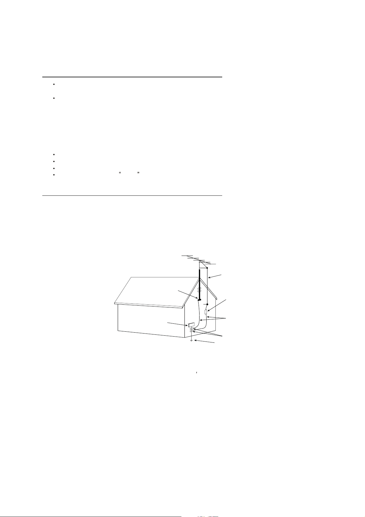
15.1. If an outside antenna is connected to the television set, be sure the antenna system is grounded so as to provide some
protection against voltage surges and built up static charges, Section 810 of the National Electrical Code, NFPA No.
70-1975, provides information with respect to proper grounding of the mast and supporting structure, grounding of the
lead-in wire to an antenna discharge unit, size of grounding conductors, location of antenna discharge unit, connection
to grounding electrode, and requirements for the grounding electrode.
EXAMPLE OF ANTENNA GROUNDING AS PER NATIONAL ELECTRICAL CODE INSTRUCTIONS
EXAMPLE OF ANTENNA GROUNDING AS PER
NATIONAL ELECTRICAL CODE
ANTENNA
LEAD- IN WIRE
GROUND CLAMP
ELECTRIC SERVICE
EQUIPMENT
NEC-NATIONAL ELECTRICAL CODE
ANTENNA DISCHARGE
UNIT (NEC SECTION
810-20)
GROUNDING
CONDUCTORS
(NECSECTION 810-21)
GROUND CLAMPS
POWER SER VICE GROUNDING
ELECTRODE SYSTEM
(NEC ART 250. PART H)
15.2. Note to CATV system installer : (Only for the television set with CATV reception)
This reminder is provided to call the CATV system attention to Ar ticle 820-40 of the NEC that provides
installer s
guidelines for proper grounding and, in particular, specifies that the cable ground shall be connected to the grounding
system of the building, as close to the point of cable entry as practical.
16. An outside antenna system should not be locatedin the vicinity of overhead power lines or other electric lights or power
circuits, or where it can fall into such power lines or circuits. When installing an outside antenna system, extreme care
should be taken to keep from touching such power lines or circuits as contact with them might be fatal.
17. For added protection for this television set during a lightning storm, or when it is left unattended and unused for long
periods of time, unplug it from the wall outlet and disconnect the antenna. This will prevent damage due to lightning
and power-line surges.
4
4
Page 5

SCHNEIDER ELECTRONICS GMBH-GERMANY
OPERATION OF YOUR SET
18.
This television set should be operated only from the type of power source indicated on the marking label.If you are not
sure of the type of power supply at your home, consult your television dealer or local power company. For television
sets designed to operate from battery power, refer to the operating instructions.
19. If the television set does not operate normally by following the operating instructions, unplugthis television set from the
wall outlet and refer servicing to qualified service personnel. Adjust only those controls that are covered in the operating
instructions as improper adjustment of other controls may result in damage and will often require extensive work by a
qualified technician to restore the television set to normal operation.
20. When going on a holiday : If your television set is to remain unused for a period of time, for instance, when you go on
a holiday, turn the television set and unplug the television set from the wall outlet.
off
IF THE SET DOES NOT OPERATE PROPERLY
21. If you are unable to restore normal operation by following the detailedprocedurein your operating instructions,
do not attempt any further adjustment. Unplug the set and call your dealer or service technician.
22. Whenever the television set is damaged or fails, or a distinct change in performance indicates a need for
service, unplug the set and have it checked by a professional service technician.
23. It is normal for some TV sets to make occasional snapping or popping sounds, particularly when being
turned on or off. If the snapping or popping is continuous or frequent, unplug the set and consult your
dealer or service technician.
FOR SERVICE AND MODIFICATION
24. Do not use attachments not recommendedby the television set manufacturer as they may cause hazards.
25. When replacement parts are required, be sure the service technicianhas used replacement parts specified
by the manufacturer that have the same characteristics as the original part. Unauthorized substitutions
may result in fire, electric shock, or other hazards.
26. Upon completion of any service or repairs to the television set, ask the service technician to perform
routine safety checks to determine that the television is in safe operating condition.
5
5
Page 6
EM BUSINESS CENTER
E
Pict
t
TERMINALS
TM
FTV PRODUCT PLANNING DEPT.
SPECIFICATION RELEAS
Version: V0.1 Issued Date: 2011.04.21
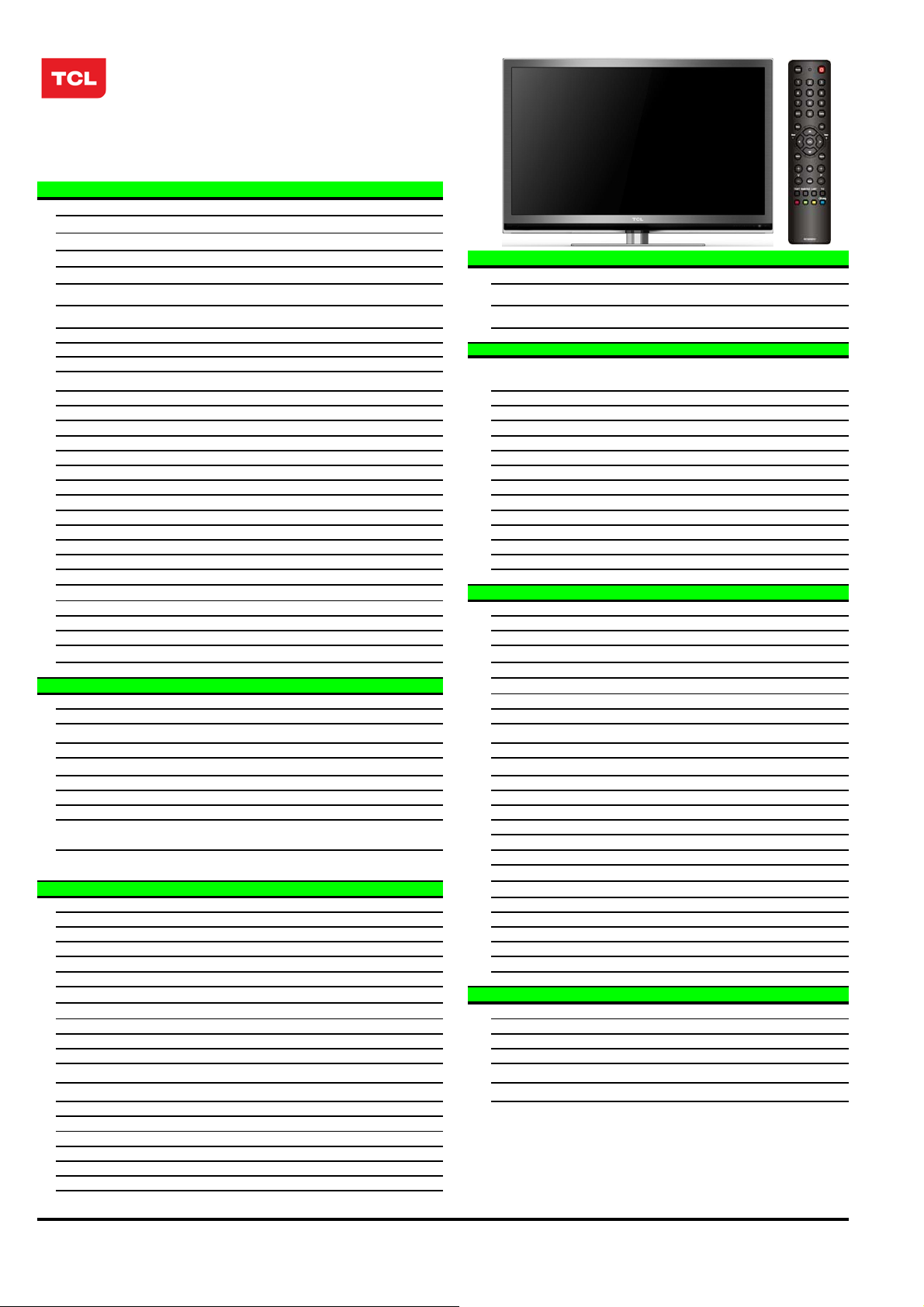
Model: L42V6200F/MT10B-LA/AUJ
PICTURE
Panel Size (inch) 42'
Category LCD TV(LED BACK LIGHT)
Aspect Ratio 16:9
Color Temperature Warm / Standard / Cold SIGNAL FORMAT CAPABILITY
Backlight Adjustable Yes Component Video Format Y,Pb/Cb,Pr/Cr:up to 720p,1080i,1080p @50Hz/60Hz
Scaler Mode Auto, Full Screen, Normal, Zoom DVI Video Format Up to XGA for HDMI-PC
Picture Effect User,Cinema,Sport,Vivid,Hi-Bright HDMI Video Format Up to 720p,1080i,1080P
Film Mode (3:2 pull down) Yes PC Compatibility VGA: up to UXGA@60Hz
ure Enhancemen
Comb Filter 3D
Core Technology
CCS -- YPbPr Input
MDDi
Blue Stretch -- YCbCr Input
Black Stretch yes Audio Input for YCbCr
Motion Compensation yes VGA Input(RGB)
DLTI yes Audio Input for RGB
DCTI yes DVI
Dynamic Skin Correction yes Audio Input for DVI
DNR yes HDMI 1.3+CEC
Panel Specification
Panel supplier AUO
Viewing Technology -- RF Input
Display Resolution 1920*1080 USB 2.0
Brightness (cd/m2) 400 Basic Info.
Contrast Ratio 4000:1 TV System ATV:NTSC PAL/M PAL/N DTV:ISDB-T
Response Time 6.5ms (G to G) AV System
Viewing Angle (H/V) 178°/178° TV Channels (Analog)
Life Time 30,000hrs (min) TV Channels (Digital)
Color 16.7M (8 bit) Chassis
SOUND Certification
Speakers speakers (Bottom side) Power Supply
Audio Power Output 8W*2 Power Consumption-TV on
Sound Processing
DVSS (Dolby Virtual Surround) -- Default Color of Front Cabinet
DDAS (Digital Dynimic Audio System) -- Keyboard Position
AVC (Auto Volume Control)
BBE
SRS
Sound Features
Sound Control
Function Base Stand
V-Chip -- Net Weight (Kg)
subtitle yes Gross Weight (Kg)
Teletext yes Container Loading
PIP/POP -- 20 feet
Macro Vision -- 40 feet
Calendar -- 40 feet high
Clock/Timers Yes ACCESSORIES
Lock Yes Operation Manual English(Default)
OSD Language English/Spanish/Portuguese Remote Control For TV control (with two batteries)
OSD Features Semi-transparent Base Stand
Card Reader -- Speaker Box
HDMI CEC Yes Wall Mount
USB Connection Yes Others AC Power cord,AV/CMP Adapter cable
Game --
Screen Saver -hotel yes
Demo Function -Picture Freeze yes
Natural light yes
High-quality scaling engine & 3-D video de-interlacer
yes Audio Input for YPbPr
BTSC (SAP, Stereo, Mono) Power Consumption-Standby
Yes
--
-MTS, AVC, Equalizer, Surround
Volume, Balance, Bass Boost
Audio/CVBS Input (Composite)
Audio/CVBS Output (Composite) 1 (R/L+CVBS)
SPDIF
Base Stand Detachable
Unpackaged Dimension for Main Body (L*H*D) (mm)
With Base Stand (mm) 1012.5*688*226
Without Base Stand (mm) 1012.5*639.2*43.5
Packaged Dimension (L*H*D)
Main Body (mm)
Speaker Box
Drafted by: 许海 2011-04-22
Approved by:
2 R/L+2 Video: AV1, AV2(Bottom)
1
1
Share with "YPbPr"
Share with Audio for "YPbPr"
1 (D-Sub,15 Pins)
1
share with “HDMI” port
Share with Audio for "VGA"
3
1 (optical)
2 (Antenna, Cable)
2
PAL,NTSC
Cable (1~125), Antenna (2~69)
Antenna (7~69)
MT5310B-LA
CB
AC 100V-240V 50/60Hz
130W
Less than 0.3W
GRAY
Front
Yes
1179*781*179
--
492.6*226*145
15kg
18.4KG
193(without pallet)
390(without pallet)
423(without pallet)
Integrated Packaging
Integrated
WMB331(Optional)
Design and specifications are subject to change without notice! Page 1 of 1
Page 7
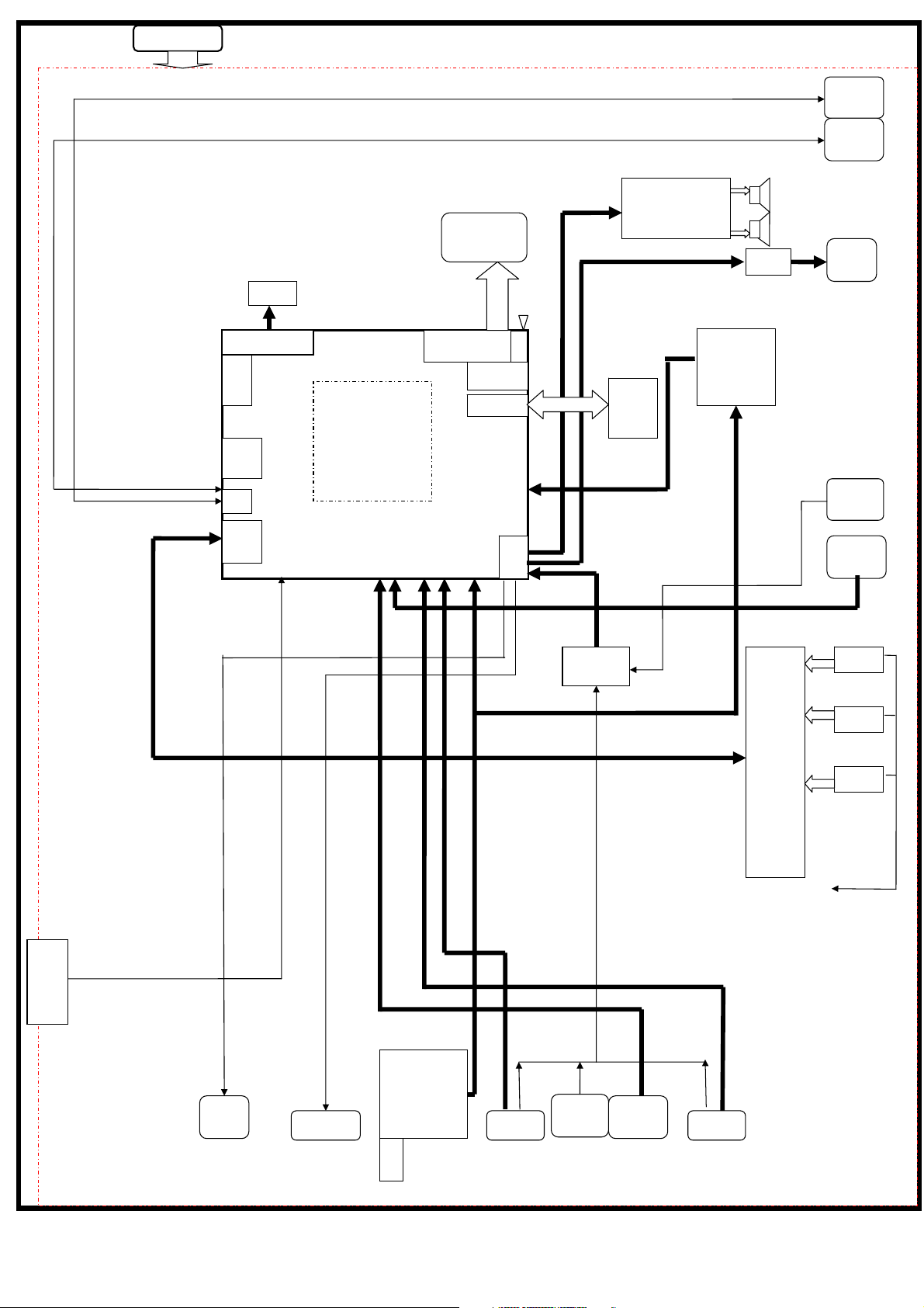
Power suppl
y
p
DDR3
Panel
USB1
USB2
Audio Amp.
AMP
DIM
LV
Head
hone
DS
DDR3
DDR3
JTA
G
USB
TMDS
I/F
MT5310
ADC
HDMI RECEIVER
CVBS DECODER
3D COMB FILTER
MPEG4 DECODER
SCALER
LVDS
IP/GPIO
FLASH
AUDIO
Nor
Flash
64Mbit
Serial TS in
4052
IF+/-
T90517
DEMO
IF+/-
HDMI 1.3
SWITCH
˄3 IN 1˅
Audio
In
YPbPr
In
HDMI1
HDMI2
HDMI3
IF+/-
CEC
IR
KEY
ISDB-T
Tuner
Spdif
Out
AV 1 In
Audio
VGA In
In
AV 2 In AV O U T
Page 8

Factory Alignment Specification of normal SIACP
TCL WW R&D
FPD CENTER
Factory Alignment Specification of normal SIACP
For MT10-LA
Version 1.0
PREPARED BY : ∳䰇 DATE : 2011-4-22
APPROVED BY : DATE :
Page 1 of 12
Page 9

Factory Alignment Specification of normal SIACP
n
o
p
TableofContents
Feature Specification ........................................................................................................................................... 4
INFO.................................................................................................................................................................... 5
1.Electrical Assembly Alignment ........................................................................................................................
1.1 Preconditions – DC/DC Check...................................................................................................................... 5
1.2 SW download ................................................................................................................................................ 5
1.3 Panel ID check and modify ........................................................................................................................... 6
1.4 Functional Test .............................................................................................................................................. 6
1.5 DDC & EDID Test......................................................................................................................................... 6
1.6 HDCP Test ..................................................................................................................................................... 7
2.Final Assembly Alignment ............................................................................................................................... 7
2.1 FactoryMenu.................................................................................................................................................. 7
2.2 Entering to “P” Mode .................................................................................................................................... 7
2.3 White Balance Alignment.............................................................................................................................. 7
2.4 High Pot. and Insulating Resistance Tests ..................................................................................................... 8
3.Factory default settings..................................................................................................................................... 8
Appendix
Appendix
Appendix
“How to download FLASH SW”................................................................................................ 11
“How to upgrade FLASH SW from USB”.................................................................................... 11
“Modify panel ID with RC” ......................................................................................................... 12
5
Page 2 of 12
Page 10
Factory Alignment Specification of normal SIACP
Disclosure
The information contained in this document is proprietary to TCL SZ FPD lab and shall not be
disclosed by the recipient to third persons without the written permission of the team leader or
GM of R&D.
Revision History
Status, Ver Date, Drafter Description of changes
V1.0 2011-4-22 This is the draft version of normal SIACP
gHDMI as the main absolute input
gThe password of factory menu is 9735
gUse RC to change project ID
gWhite Balance
Page 3 of 12
Page 11
Factory Alignment Specification of normal SIACP
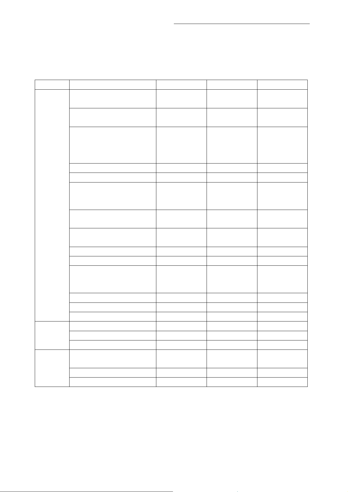
FeatureSpecification
These chassises are designed for South America LCD TV. The main chip is from Mediatec
(MT5310 series) and supports below inputs and outputs:
class item Status MT10B-LA MT10L-LA
¥ Cable&Antenna Cable&Antenna
¥ Antenna Antenna
3 P300
P301
P302
1 P406 P406
1 P400 P400
1P1
P455 (Audio)
2 P304
P404
2 P303
P401
¥ P800 P800
Optical P405 P405
1 P498 P407
P301
P302
P303
P404
P423
P421
P401
P427
P424
P425
Input
&
Output
ATV
( PAL- M/N, NTSC-M)
DTV
(SBTVD-T)
HDMI
(480i/p, 576i/p, 720p up to
1080i/p, compliant v1.2. with
HDCP)
VGA
VGA/DVI audio
CMP
(YPrPb can support from 480i
up to 1080p,audio)
Side AV or back AV
(CVBS,audio)
USB player
(picture,video,audio)
Headphone output
SPDIF output
AV out
function
Others
VGA connector of MT5310B definition:
VGA: Pin4:RXD VGA Pin11:TXD
Page 4 of 12
Page 12
Factory Alignment Specification of normal SIACP
n
INFO
ª All tests and measurements mentioned hereafter have to be carried out at a normal mains voltage
(220 ~ 240 VAC)
ª All voltages have to be measured with respect to
ª All final tests have to be done on a complete set including LCD panel in a room with temperature of
25+/-7°C
ª The White Balance (color temperature) has to be performed into subdued lighted room after at
least 1 hour of warm-up/burn-in. This is applicable for both Alignment and Picture Performance
evaluation at OQA in order to be set free of any temperature drift ( colorimetry vs time)
ground, unless otherwise stated
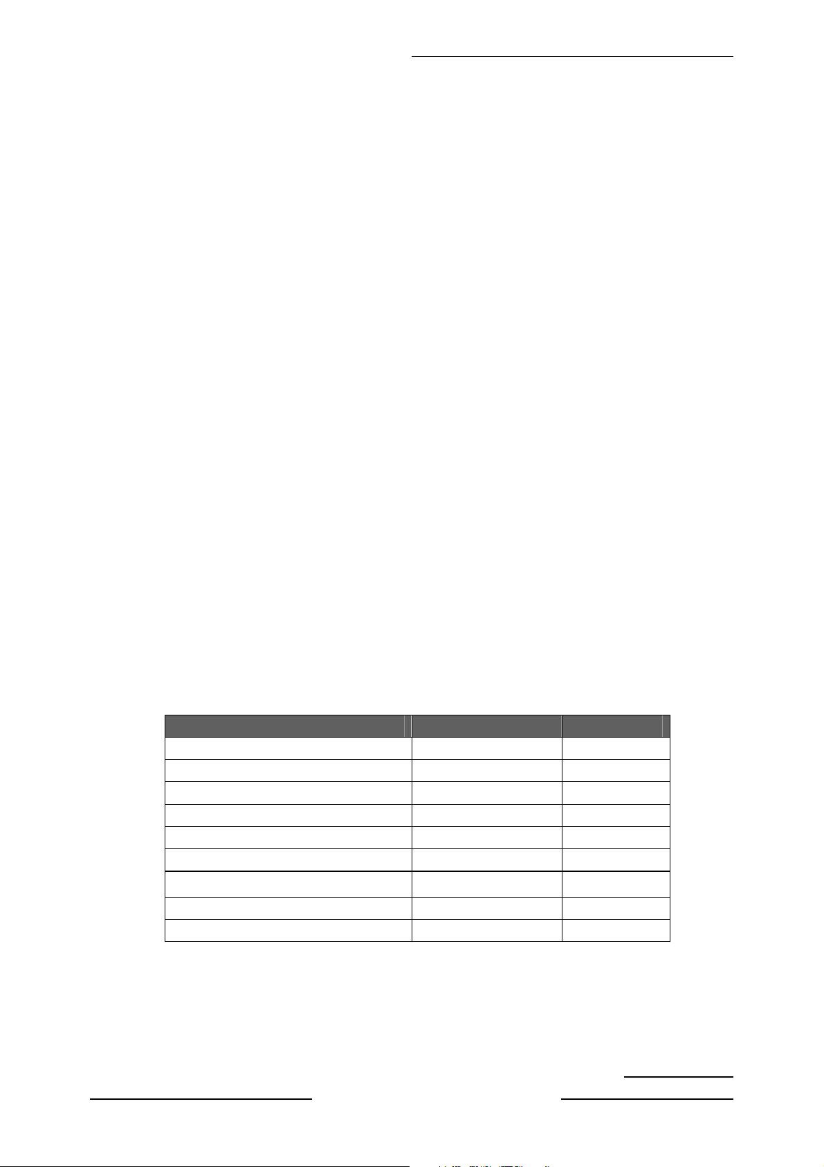
1.ElectricalAssemblyAlignment
1.1 Preconditions – DC/DC Check
Before power on, please check the board according to the relevant block diagram and circuit
diagram, and make sure that no serious error should destroy the board. For example,the output
of DC/DC and LDO should not shorted to ground.
Supply a suited voltage and power on , then check the voltage according to the relevant
block diagram , circuit diagram and voltage spec . the error should less than 5% .For example,
the voltage for main chip(DV33, AV33, VCCK,etc.), the voltage for DDR (DDRV) , the voltage for
amplifier(AUDIO_PWR),etc. Only the standby voltage is necessary if there is no software in the
flash .
Position Value Remarks
R111 3.3V +/-5% +3V3SB
C117 (positive pin) 5.0V +/-5% +5V
C101 (positive pin) 1.1V +/-5% Vcck
U105 1.2V +/-5% AVDD1V2
U104 3.3V +/-5% DVDD3V3
U109 3.3V +/-5% A VDD3V3
U12 1.5V +/-5% DDRV
C100 (positive pin) 12V +/-5% +12V
U102 5.0V +/-5% TUNER_VCC
Note: Different model may have different configuration of DC/DC circuit.
1.2 SW download
Download the latest release MT10_SW into the flash using MTK SW tool. See Appendix
“How to download FLASH SW”
. Or upgrade the SW from USB port See Appendixo “How to
Page 5 of 12
Page 13
Factory Alignment Specification of normal SIACP
p
upgrade FLASH SW from USB”.
Remenber to do “Reset all” after upgrade the SW.
1.3 Project ID check and modify
There is different ID stored in the NVM depended on different Panels. Modify it with Hyper
terminal if the initial ID or a wrong ID make the set can not display clearly. See Appendix
. It can
be checked and modified in Factory menu->Project info->Project ID if the set can display
clearly . The set should be restart if the project ID is changed .
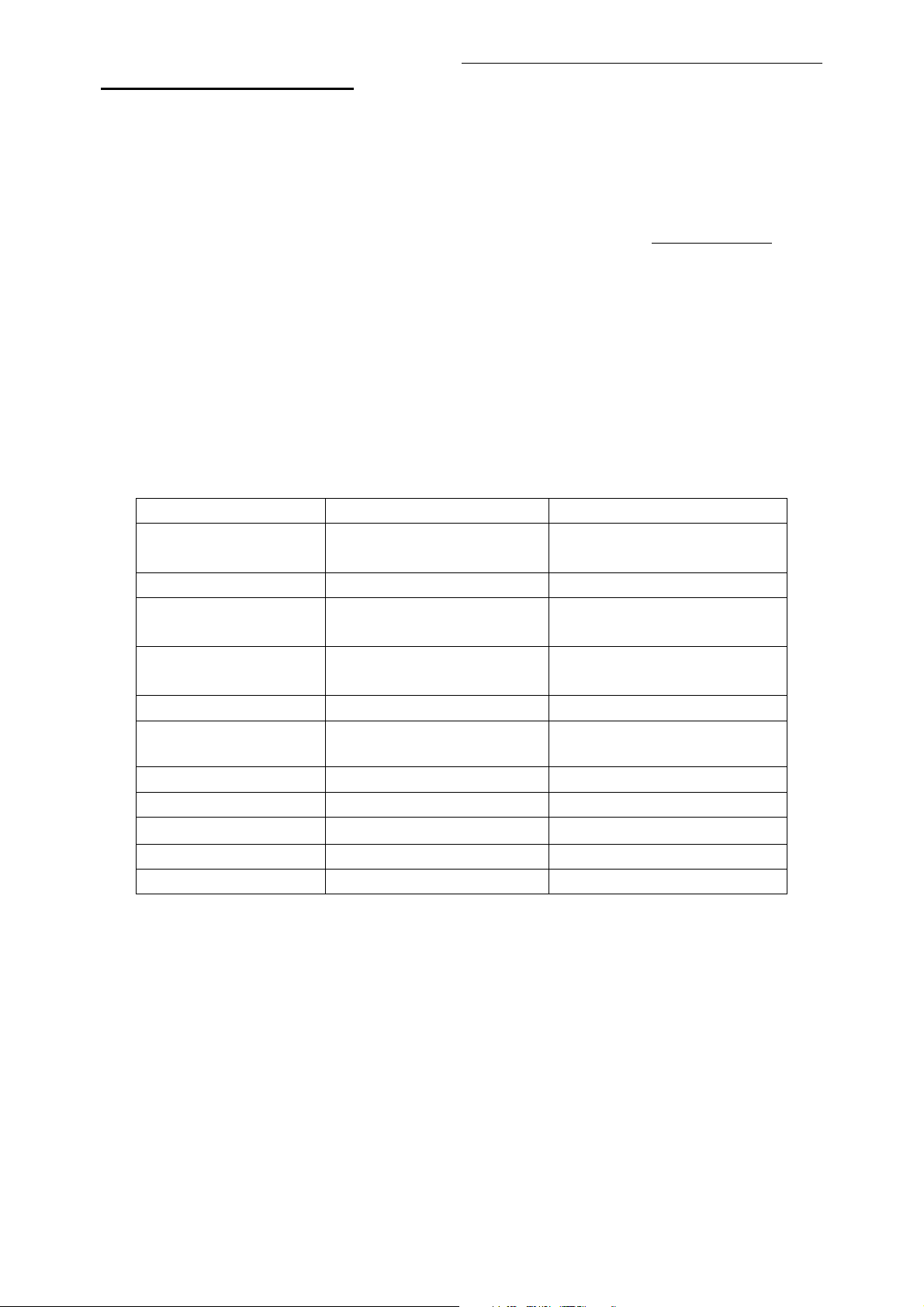
1.4 Functional Test
Once the boards (chassis, KB, IR, PSU…) and the panel are well interconnected, connect all
external generator devices to relevant inputs/outputs below according to their respective test
patterns format and check picture content and sound quality accordingly
Source Test signal (generator) Test pattern (format/image)
Analog /Digital Tuner RF cable Full Band (VHF/UHF) + CATV
Composite(CVBS) Chroma/Fluke PAL Half Color & Gray bars
VGA Chroma/QuantumData 1024x768@60Hz
Half Color & Gray bars
CMP (YPrPb) Chroma/QuantumData 1080i@60Hz
Half Color & Gray bars
HDMI DVD with HDMI compliancy Movie 720p@60Hz
Headphone RF cable First channel
:
SBTVD-T
Loud Speakers RF cable First channel
USB USB device Picture musica Video
Audio tones can be defined by the factory (ie: 1KHz & 3KHz, sweep, …).
Picture video formats can be changed by the factory according to their own standard.
1.5 DDC & EDID Test
The E-EDID data structure are according to VESA Enhanced EDID 1.3 (and EIA/CEA-861B for
HDMI).
HDMI have their own separate bin files:
For EDID check, it’s needed to check whether the correct EDID is downloaded by checking
corresponding EDID NVM Checksum or read them out to check bit by bit if it is in line with the
released EDID bin file.
Page 6 of 12
Page 14

Factory Alignment Specification of normal SIACP
1.6 HDCP Test
For HDCP compliancy, it’s needed to check whether the HDCP key has been well set.
2.FinalAssemblyAlignment
2.1 FactoryMenu
Follow the below steps to pop-up the Factory Menu in case of “FactoryKey” is disable
press RemoteControl key “MENU” to display main menu
-
- Select “Picture” and press “OK” key to enter the picture submenu
- Select “Contrast” item
press the subsequence RemoteControl keys “9”, “7”, “3” and “5”
-
Press RemoteControl key “Return” To pop-up the Factory Menu in case of “FactoryKey” is
enable.
The status of “Factory Key” can be changed in
Press RemoteControl “OK” key or “RIGHT” key to enter the submenu.
Press RemoteControl “Menu” key to go back to the root menu.
Press RemoteControl “RIGHT”or “LEFT” key to change the values.
Press RemoteControl “OK” key run the function.
Press RemoteControl “Exit” key exit the factorymenu.
Factory Menu->Hotkey
:
2.2 Entering to “P” Mode
Turned on the factory key to enter into “P” mode.The TV will display the following info in
bottom left corner in “P” mode.
-main version ***
-project ID ***
-P/PS/D ***
2.3 White Balance Alignment
Make sure that the picture mode is “vivid”, enter to “P” mode(turned on the factory key) and
switch off “Pic. Enhance” in Factory Menu-> White Balance before white balance alignment .
VGA,CMP, DTV,CVBS_PAL Color Coordinates are relative to HDMI.
CVBS_SECAM and CVBS_NTSC Color Coordinates are relative to CVBS_PAL.
Warm and Cool Color Coordinates are relatives to Normal mode.
Only HDMI(YUV 720p@60Hz) input requires color temperature adjustment.
Matrix Offsets should be set while doing alignment.
Page 7 of 12
All the Relative
Page 15

Factory Alignment Specification of normal SIACP
¡
Each panel has it’s own colour coordinates, Please refer to the following table.
㪛㫐㫅㪸㫄㫀㪺㪆㪎㪇㩼㩷㪮
Normal 0.275 0.310 0.275 0.290 0.280 0.290 0.280 0.290
Cool 0.265 0.285 0.265 0.290 0.270 0.280 0.270 0.280
Warm 0.305 0.330 0.305 0.330 0.312 0.330 0.320 0.320
L32V6200/L32E5200 L42E5200F/L42V6200F C32E320/L32P60 C42E320F/L42P60F
xyxyxyxy
Expected Targets and Tolerances
The measured parameters should be “x, y” coordinates.
The White Balance alignment should be performed using a contact less analyzer (ei: Minolta
CA-210). The analyzer may not touch the screen surface, and measurement must be performed in a
dark environment keeping the probe(s) at 90+/-2° from the panel.
The result should measure up the relevant spec.
2.4 High Pot. and Insulating Resistance Tests
At the end of the process, a High Pot. and an Insulating Resistance tests are required for
matching Safety Electrical requirements (ei: xxxx)
High Voltage Withstanding requirements
- “Voltage” Ö 3500 VAC
- “Max Leakage Current” Ö 10 mA
- “Test Time” Ö 5 sec
Insulating Resistance requirements
- “Voltage” Ö DC500V
- “Threshold Min” Ö 4M
- “Test Time” Ö
3 sec
3.Factoryde faultsettings
Do the “Reset shop” before packing.The detail of reset shop follow OOB setting.
“Factory Menu” Definition
1)ˊ Hotkey
Item Sub-item Value Note
Hotkey
2)ˊBurning Mode
Off/On
Page 8 of 12
OFFġhotkey is invalid
ON ġhotkey(Return key) is availability
Page 16
Factory Alignment Specification of normal SIACP
˄
˅
Item Sub-item Value/Sub-item Note
Burning
Mode
Off/On
Select panel On with left/right
key, Press “EXIT” key to enter
the burning mode;
Press “Menu” key on keyboard
to exit the burning mode
3)ˊ ADC
4)ˊ W
Need not to do ADC when alignment
hite Balance
Item Sub-item Value Note
White
Source HDMI,etc
Balance
Color Temperature Normal
/Warm/Cool
R Gain
G Gain
B Gain
R Offset
G Offset
B Offset
White Balance Init
Pic. Enhance On/Off
Picture related Flesh tone
Adaptive luma
control
Light sensor
Dynamic
backlight
Back light
For balance source˖
HDMI,VGA,DTV,PAL,SECAM,NTSC,Scar
t RGB,CPM, HDMI
The value of Warm and cool is the offset
of Normal mode. Cool is the preset status
R White balance
G White balance
B White balance
R Gray balance
G Gray balance
B Gray balance
Press “Right” key to initial the preset RGB
Gain/Offset value
Press “Right” key to switch off all of the
items in the feature submenu. This should
be done before white balance alignment.
If it’s off, the way to switch it on is to reset
user/shop or set on the features in
Feature sub-item manually.
Select On/Off to open/close the function
Select On/Off to open/close the function
Select On/Off to open/close the function
Select Auto/High/Mid/Low to set the
backlight control
0~100 Set the backlight
5)ˊReset Shop
Item Sub-item Value Note
Reset
Shop
Page 9 of 12
Clear date of NVM in user menu,include
the value related installation,and Clear
date of factory menu except the item of
Balance and sound ,set to default value
Page 17
Factory Alignment Specification of normal SIACP
ˊ
6)ˊ Reset ALL
Item Sub-item Value Note
Reset
ALL
7)ˊ Power Mode
Item Sub-item Value Note
Power
Mode
Boot/Standby/
Last Status
Clear NVM valuesˈ and set to default
value
Boot: Enter power on mode
Standby: Enter standby mode
Last Status: power on according to last
status
8)
USB Clone Mode
Item Sub-item Value Note
USB
Clone
Mode
USB Clone Mode All/ChannelList
/EEPROM/
User Setting
TV TO USB DO
USB TO TV DO
9)ˊ Other
Item Sub-item Value Note
Project
info
Project ID ***
Project Name ***
Panel ID ***
Panel ***
Version ***
Date ***
Time ***
MCU Version ***
RCU ***
PSU ***
Region ***
Product S/N ***
Tuner
AGC
Select to choose the things you want to
clone
Press “Right” key to copy the
data(WB,ADC,picture setting,etc) to USB
Press “Right” key to set the
data(WB,ADC,picture setting) from USB
Page 10 of 12
Page 18

Factory Alignment Specification of normal SIACP
Appendixn“HowtodownloadFLASHSW”
Prepare MTK SW tool for update.
1. Connect the PC to the serial connector on board using a
COMx).
2. Provide the a correct voltage to the board
3. Start “MTKTOOL.exe” application under MTKxx folder, and set the parameters as below
picture(notice:select MT536X chassiss):
special serial device (USB or
4. Press “Browse” button to select the co
5. Press “Upgrade” button then press “NOR” button to start downloading the SW and wait the
gauge displayed “100%” that means the SW has been successfully downloaded.
In the meanwhile, all operations such erasing flash and so… are parsed into the debug
window script.
6. Once the SW is downloaded, switch-off/on the chassis board and wait few seconds for
eeprom update.
rresponding SW bin file to upload
Appendixo“HowtoupgradeFLASHSWfromUSB”
Upgrade with loader:
1. Save the new software file(*.pkg) in the root directory of USB, and modify it’s name as
upgrade.pkg.
2. Plug in the USB when TV set is “power off” or “standby” (TV set should be on “standby” status
if using a touch sensing keyboard).
3. Press down “power” key on keyboard, power on if it is on “power off” status , release the
“power” key 2~5 second later , the LED on IR board will flash after upgrade begin, the TV set
will start up if upgrade succeed.The LED is on but no flash if upgrade fail,check the set and
Page 11 of 12
Page 19

Factory Alignment Specification of normal SIACP
try again.
Upgrade without loader(The TV set should be able to display normally):
1. Save the new software file(*.pkg) in the root directory of USB, and modify it’s name as a
software number, such as “V8-0MT1006-LF1V017.pkg”.
2. Plug in the USB.
3. Upgrade the SW follow the indication display on the screen
Appendixp“ModifypanelIDwithRC”
“Modify panel ID without panel but via a RC”
¾ 062598+MENU+xxx (xxx:Panel ID)
Page 12 of 12
Page 20

PAN_ON/OFF
L118
600R
R143
Q102
3V3SB
C
B
10K
R142
R141
10K
4K7
R140
ADIN3_SRV
LO = > POWER_ON
HI = > POWER_OFF
+5V
Back Light circuit
MAIN_POWER
MAIN_POWER
T
+24V
47K
BT3904
E
GND_P1
1
2
T
345678
ON/OFF_PWR
+5V
DIMMING
DVDD3V3
PANEL_DIM
T
PANEL_DIM
9
1112
10
T
PAN_ON/OFF
ON/OFF_PWR
STB_POWER
STB
P100
T
PAN_ON/OFF
3V3SB
R131
NC/3K3
T
T
GND_P2
T
R111
0R
3V3SB
D110
NC/LL4148
1K
R132
NC/10K
R144
STB_POWER
3V3SB
U110
STB_POWER
ON/OFF_PWR
NC/4K7
R145
R153
PANEL_DIM
600R
L121
VBR_EXT
0R
R130
NC/0R
R116
C158
2
GND
NC/RT9166-33
IN OUT
3
C147
NC/0.1U
Q103
NC/BT3904
C
B
R156
10K
NC/10K
OPWRSB
C105
NC/1U
E
C
B
Q104
4K7
R115
BL_DIMMING
C132
0.1U
1
E
BT3904
6V3
C114
6V3
C115
1U
NC/100U
NC/100U
10K
R157
STB_POWER
R152
8K2
12V
D108
LL4148
protection circuit
+5V
ON/OFF_PWR
R154
100R
Q107
E
BT3906
B
1K
C
R155
VCCK
T
VCCK
R119
15UH
L100
R118
100K
L120
12V
BT3906
Q106
E
3V3SB
B
R146
4K7
2K2
R151
LL4148
D107
TUNER_VCC
GND
C159
0.1U
16V
470U
C101
4U7
C104
20K
4K7
R120
220P
C156
0.1U
847
SS
EN
BSINSW COMP
U107
1236
0.01U
C127
0.1U
C160
16V
C121
100U
C134
2K2
R128
C128
3300P
5
FB
MP1484
GND
60R
470P
C168
PANEL_DIM
0.1U
C163
PAN_ON/OFF
C162
0.1U
ON/OFF_PWR
0.1U
C167
STB_POWER
C135
0.1U
MAIN_POWER
close to P100
12V
ADIN2_SRV
R148
4K7
C
LL4148
D105
DVDD3V3
L500
L109
RESET_24V
L111
MAIN_POWER
R147
LL4148
D106
DVDD3V3
T
NC/200R
NC/200R
200R
4K7
AVDD3V3
U104
L105
200R
GND/ADJ
OUT
4
LD1117S33
D102
LL4148
C126
1K8
R149
LL4148
D103
1
234
VIN
+5V
+5V
T
+5V
Max 5.4A 17mo
D13N03LT
RT8110B
U106
0.1U
0.1U
C138
1U
NC/470U
C118
C199
220U
DDRV
L106
10UH
35V
L102
D2B
G2
UGATE
BOOT
C109
35V
200R
5
5
R150
DVDD3V3
L107
200R
C106
6
D1B
D2A
G1
S2
3
3
GNDPHASE
2K2
L116
NC/AZ1084
U108
Z103
T
NC/10U
C117
R125
4R7
4R7
R163
7
D1A
241
S1
264
LGATE
VIN
7
L122
12V
200R
23
C165
VCC
FB
600R
VOUTVIN
8
1
8
C103
C129
0.1U
ADJ/GND
C130
0.1U
NC/100U
0.1U
16V
470U
R127
Q100
1U
C111
C145
C113
100U
6V3
C144
U102
6V3
1
3K6
C148
2U2
TUNER_VCC
GND/ADJ
4
OUT
4
VIN
LD1117S50/3V3
Z102
12V
AVDD1V2
T
330R
R101
680R
+/-1%
R126
0.015U
3300P
Vout=0.8*(680+3600)/680=5.035
L108
T
TUNER_VCC
1
2
3
T
R114
10V
R112
GND/ADJ
4
OUT
4
U105
AS1117AD
200R
C154
0.1U
C119
NC/100U
16V
C155
0.1U
C110
47U
16V
6R8
6R8
R113
NC/12R
C120
16V
NC/100U
+5V
C161
0.1U
AVDD1V2
AVDD1V2
C112
100U
6V3
120R
R100
1
2
3
VIN
0.1U
C133
R105
AVDD3V3
T
2R7
12V
200R
200R
L114
L115
C108
10U
NC/0.1U
C124
T
12V
C100
470U
1U
C140
16V
R122
15UH
L103
SR34
D100
0.1U
C143
847
SS
EN
U100
MP1593DN
BSINSW COMP
C125
0.01U
1236
C139
0.1U
L113
L112
200R
200R
MAIN_POWER
U111=13-AZ1084-ADBE1
DDRV
23
DDRV
VOUTVIN
1
ADJ/GND
NC/AZ1084
U12
AVDD3V3
2R7
R106
1
GND/ADJ
2
4
OUT
4
3
VIN
U103
NC/LD1117S33
+5V
GND
R123
110K 1%
GND
GND
R121
5
FB
GND
GND
GND
C116
NC/470U
35V
35V
C198
220U
T
AZ1117
U111
6R8
R159
6R8
R160
C171
NC/47U
12K4 1%
C142
5K6
23
C166
0.1U
C122
6V3
NC/100P
C141
POWER
C175
0.1U
GND
220U
6V3
C173
22R
R162
U109
AZ1084
GND
GND
GND
23
VOUTVIN
1
ADJ/GND
110R/1%
R161
VOUTVIN
1
ADJ/GND
C174
0.1U
16V
C172
100U
6V3
100U
0.1U
C131
GND
GND
8200P
Page 21

TU200
TU201
DEMOD BD CONNECTOR for ATSC
TUNER_VCC
TUNER_FAT-
TUNER_FAT+
L209
C211
NC/0.1U
TUNER_CLOCK
TUNER_DATA
TUNER_IF_AGC
C235
56P
NC/0.22UH
L299
C236
56P
R_AGC
TTT
T_SCL
T_SDA
T_VCC
T
120R
C205
0.01U
0.1U
C210
C201
100U
16V
RF_AGC
IF_AGC
T
C223
10K
0.047U
TUNER_FAT+
TUNER_FAT-
GND
C207
NC/0R
R207
NC/47P
C228
0.01U
NC/33P
L200
NC/0.33UH
C206
C203
NC/47P
NC/0R
0.01U
C229
R208
band filter struction follow MT5310
R204
R213
123
10K
NC1
0R
0R
NC2
L208
C202
R234
R235
NC3
TUNER_RF_AGC
600R
0.047U
IF_AGC
B+
RF-AGC
5
6
TUNER_VCC_1
C204
C209
10P
10P
FAT-_D
220P
C308
FAT+_D
SDA
T_SDA
0.22UH
L216
SCL
T_SCL
Z226
T
NC5
NC4
DIF+
DIF-
8
947
10
11
TUNER_FAT-
TUNER_FAT+
T
FAT-
T
FAT+
L206
R206
100R
220R
L207
R205
220R
100R
RF-AGC
13245
TUNER_RF_AGC
TUNER_DATA
TUNER_CLOCK
NC2
NC1ASSCL
T_SCL
AS
R209
0R/NC
AS
T
SDA
+B
6107
T1_VCC
T_SDA
L210
120R
TUNER_VCC_1
AIF
8
9
T
C212
0.1U
TUNER_IF_AGC
DIF+
IF_AGC
0R
R227
TUNER_FAT+
DIF-
11
TT
0R
R228
TUNER_FAT-
F+
F-
GND
DEMO_DATA6
DEMO_DATA4
DEMO_DATA2
DEMO_DATA0
DEMO_VALID
DEMO_SYNC
GND
OSCL0
P201
18
16
14
12
10
8
6
4
17
15
13
11
9
7
5
3
12
DEMO_DATA7
DEMO_DATA5
DEMO_DATA3
DEMO_DATA1
GND
DEMO_CLK
GND
DEMOD_RESET
OSDA0
D_CLK
T
D_VALID
T
DEMO_VALID
DEMO_SYNC
TUNER_VCC
DEMO_DATA0
R217
R216
4K7
4K7
C219
10P
R201 NC/100R
C220
10P
R203
R202
100R
100R
NC/100RR200
TUNER_SCL
TUNER_SDA
OSCL0
OSDA0
D_SYNC
T
D_FAT+
T
D_DA0
T
R221
33R
D_FAT-
T
R220
R219
R218
Z209
T
OSDA0
T
GPIO_4
33R
33R
33R
T
OSCL0
GND
D_IF_AGC
GND
DEMOD_FAT-
DEMOD_FAT+
GND
DEMOD_RST
TS_VALID_IN
TS_SYNC_IN
TS_CLK_INDEMO_CLK
Z227
T
OSCL0
OSDA0
R210
4K7
TS_D0_IN
14
12
10
8
6
4
P200
13
11
9
7
5
3
12
R215
DEMOD_RESET
0R
DEMO_POWERDOWN
C222
10P
DEMO_POWERDOWN
GND
TUNER_SCL
TUNER_SDA
NC
GND
AVDD3V3
C218
10P
D_RESET
T
C221
10P
TUNER_SCL
T
C217
TUNER_SDA
T
10P
D_POWER
Z223
T
T
GND
+5V
U200
5
1
NC/0R
R211
10K
AOSDATA1
4
C227
E
0.1U
VCC
Y
GND
Z
74LVC1G66GV
3
2
R223
A_RF_AGC
L213
L211
C309
5P6
0.12UH
0.12UH
C234
Close to tunter
GND
D_IF_AGC_1
U201
1
B2
2
GND
NC/74LVC1G3157
R222
0R
R212
0R
C224
NC/0.1U
GND
CLOSE TO MT5135
6
S
5
VCC
43
AB1
R214
0R
D_IF_AGC
NC/33P
NC/33P
C213
NC/0R
NC/0R
R231
R230
C233
C232
0.01U
0.01U
C208
C230
NC/0.01U
C231
NC/0.01U
FAT_IN-
FAT_IN+
5135_FAT-
5135_FAT+
C237
220P
FAT_C_IN-
L212
NC/0.22UH
C239
NC/220P
FAT_C_IN+
5P6
C238
220P
FAT-_D
FAT+_D
R224
180R
R226
NC/49R9
R225
180R
R233
NC/49R9
R229
NC/75R
R232
NC/49R9
R299
DEMOD_FAT-
0R
R298
DEMOD_FAT+
0R
A_IF_AGC
D_IF_AGC_1
AOSDATA1
IF_AGC
C225
NC/0.1U
+5V
C226
0.1U
C200
NC/10U
GND
GND
RF_AGC
TUNER/DEMOD BD
Page 22

HDMI1_ARC
R365
GPIO_0
0R
P304
Y/AV
PR/L
PB/R
GND
P302
RX2+
GND1
RX2-
RX1+
GND2
RX1-
RX0+
GND3
RX0-
RXC+
GND4
RXC-
NC1
NC2
DDCCLK
DDCDA
GND5
VCC
HPD
HDMI1
MT10L_SPDIF
NC/10K
R351
10K
R350
MNT-HOLE2
MNT-HOLE1
GND-1
DPOS-1
DNEG-1
VCC-1
P303
AV1 IN(side)
AV1L_IN
5
4
3
AV1R_IN
2
CVBS_1
1
AV1_GND
T
1
2
3
4
5
6
7
8
9
10
11
12
13
14
15
16
17
18
19
2
1
6
5
4
3
2
1
GND
U304
74LVC1G125GW
A
OE
Z300
T
AVDD3V3
5
VCC
GND
3
RX1B2P
RX1B2N
RX1B1P
RX1B1N
RX1B0P
RX1B0N
RX1BCLKP
HDMI1_ARC
100R
R332
DDC1BSDA
C315
NC/10P
RX1BCLKN
HDMICEC
DDC1BSCL
C313
0.1U
4
Y
CVBS_1
R308
47K
47K
R310
10K
R309
100R
R331
R352
180R
USB PORT 1
U1_POW
T
F300
AV1_L
T
T
T
AV1L_IN
AV1R_IN
GND
U1-
T
AV1_R
R338
T
C311 0.1U
HDMI_SCL
R322
4K7
4K7
R316
M_RX1_CB
M_RX1_C
46
SCL_SINK
HPD_SINK
Y1
Z1
SCL2
SDA2
B21
32548
DDC2BSDA
RX2BCLKN
DDC2BSCL
DDCCLK
HDMI3
DDC2BSCL
DDC2BSDA
M_RX1_0B
M_RX1_0
42
41
Y2
GND3
PS331
POW2
A21
B22
7
RX2B0N
RX2BCLKP
36K
R325
HDMI2_5V
RX2+
RX2-
GND2
RX0+
RX0-
GND4
NC1
GND5
HPD
M_RX1_1B
Y3Z3Z2
U300
A22
GND1
9
RX2B0P
P300
GND1
RX1+
RX1-
GND3
RXC+
RXC-
NC2
DDCDA
VCC
VCC_HDMI
VCC_HDMI
M_RX1_2B
M_RX1_1
37
38643940434445
36
Z4
VCC3
Y4
VCC1
A23
B23
121110
VCC_HDMI
RX2B1N
RX2B1P
M_RX1_2
SCL_CTL
I2C_ADDR
B24
A24
15
14
RX2B2N
RX2B2P
R326
1
2
3
4
5
6
7
8
9
10
11
12
13
14
15
16
17
18
19
333435
SDA_CTL
POWDN
REXT
GND2
VCC2
SDA1
I2C_RST
POW1
HPD1
16
HOTPLUG1
36K
HDMI1_5V
RX3B2P
RX3B2N
RX3B1P
RX3B1N
RX3B0P
RX3B0N
RX3BCLKP
R303
R301
100R
R317
100R
100R
R318
HDMI3_5V
1K
R300
C
R346
100K
Q303
10K
R302
33R
R319
470R
BT3904
OSCL0
OSDA0
E
B
U303
1
A0
2
A1
3
A2
4
GND
3V3SB
AVDD3V3
NC/4K7
R348
HOTPLUG3
1K
R349
4K7
HDMI3_EDID
H:WP,L:WRITE
8
VCC
7
WP
6
SCL
5
SDA
AT24C02
WP_3
HDMICEC
D300
LL4148
L300
200R
HDMI3_5V
R337 10K
T
T T
SCL_3
R336
R333
27K
0.1U
10U
C307
C303
H3_GND
SDA_3
0.1U
C300
T
C312 0.1U
100R
0.1U
C302
C301
0.1U
DDC3BSCL
DDC3BSDA
HDMI_CEC
VCC_HDMI
RX3BCLKN
HDMICEC
47K
47K
100R
R327
R328
DDC3BSCL
DDC3BSDA
VCC_HDMI
NC/0R
4K7
R321
R323
C306
C305
22P
22P
32
31
30
A14
29
B14
28
NC1
27
A13
26
B13
25
24
A12
23
B12
22
21
A11
20
B11
19
SCL1
18
17
R320
RX1B2P
RX1B2N
RX1B1P
RX1B1N
RX1B0P
RX1B0N
VCC_HDMI
RX1BCLKP
RX1BCLKN
DDC1BSCL
DDC1BSDA
HDMI
P301
1
RX2+
GND1
RX2-
RX1+
GND2
RX1-
RX0+
GND3
RX0-
T
C310 0.1U
GND4
NC1
DDCCLK
GND5
HPD
HDMI2
DDC1BSCL
DDC1BSDA
RXC+
RXC-
NC2
DDCDA
VCC
100K
HDMI1_5V
Q301
BT3904
R311
NC/4K7
B
R340
1K
R341
R339
HDMI1_EDID
1
2
3
4
HOTPLUG1 HOTPLUG2
4K7
H1_GND
AT24C02
VCC
SDA
WP
SCL
8
7
6
5
WP_1
H:WP,L:WRITE
HDMI1_5V
R334 10K
T
T T
SCL_1
SDA_1
U301
A0
A1
A2
GND
1K
C
E
+5V
NC/1K2
R355
C314
R354
56R
82R
R353
U1+
T
C316
F301
NC/10P
F302
F304F303
NC/10U
CVBS_1
L301
L302
R356
2R2
R357
2R2
C317
C318
0.1U
R359
75R
30R
30R
C324
470P
HDMI1_ARC
1U
5K1
R364
+5V
USB_DP1
USB_DM1
L303
60R
C319
100U
6V3
C320
R358
0.01U
100R
C321
47P
GND
R360
10K
R361
10K
C325
470P
R362
5K1
R363
CVBS1P
C322
2U2
AV1_L_IN
C323
2U2
AV1_R_IN
5K1
RX2B2P
2
3
RX2B2N
RX2B1P
4
5
RX2B1N
6
RX2B0P
7
8
RX2B0N
9
10
RX2BCLKP
11
RX2BCLKN
12
13
HDMICEC
14
15
16
17
18
19
100R
R329
DDC2BSDA
R307
47K
R305
47K
100R
R330
DDC2BSCL
R306
10K
HDMI2_5V
R304
1K
C
B
R342
100K
Q302 R347
E
BT3904
NC/4K7
HDMI_HPD1
NC/4.7K
HDMI3_5V
R324
36K
RX3B2P
NC/4K7
R344
1K
R345
R343
4K7
HDMI2_EDID
U302
8
1
VCC
A0
7
2
WP
A1
6
3
SCL
A2
5
4
SDA
GND
AT24C02
VCC_HDMI
R314
C
R315
B
NC/4K7
R312
HOTPLUG3
DDC3BSDA
DDC3BSCL
RX3BCLKN
RX3BCLKP
RX3B0N
RX3B0P
RX3B1N
RX3B1P
VCC_HDMI
RX3B2N
H:WP,L:WRITE
WP_2
NC/4K7
R313
Q300
NC/BT3904
E
C304
2U2
HDMI2_5V
R335 10K
T
T T
SCL_2
POW_SINK
49
HPD3
50
SDA3
51
SCL3
52
B31
53
A31
54
POW3
55
B32
56
A32
57
GND4
58
B33
59
A33
60
VCC4
61
B34
62
A34
63
CEXT
H2_GND
SDA_2
(9)
HDMI_SDA
47
48
SDA_SINK
HPD2
1136
HOTPLUG2
GND
Page 23

YPBPR1 IN
IF
N
P404
6
GREEN
5
4
BLUE
3
2
RED
1
P410
4
WHITE
3
2
RED
1
SPDIF OUT(OPTICAL)
C422
MT10L_SPDIF
ear Connector
R430
33R
0.1U
C480
NC/0.033U
VGA CONNECTOR
P406
16
5
15
10
4
14
9
3
13
8
2
12
7
1
11
6
17
R428
NC/100R
VSYNC_IN
GND
VGASCL_IN
BLU
HSYNC_IN
GRN
VGASDA_IN
T
Z429
GND
YUV_R
T
SPDIF
T
SPDIF_GND
VGA_RXD
RED
VGA_TXD
VGA_TXD
R482
100R
R481
100R
R483
100R
R484
C
GND
C450
1500P
C449
0.01U
C448
0.01U
C447
0.01U
C446
0.01U
YPBPR1_L_IN
YPBPR1_R_IN
U0RX
Function Select
F404
100R
F405
close to MT5310
SOY1
Y1P
COM1
PB1P
PR1P
Function Select
SCT1_FS_IN
R443
10K
F414
R412
NC/V270RA
21
GND
VGA_PLUGPWR
R444
VGASCL
100R
10P
C412
VGA_PLUGPWR
VGASDA
C413
10P
R464
SCART_FS0
R470
1K8
close to VGA connector
R421
10K
R420
10K
P1
Y/AV
PR/L
PB/R
GND
GND
P455
ONLY FOR EM MARKET
SCART IN
1
2
3
4
5
6
7
8
9
10
11
12
13
14
15
16
17
18
19
20
21
22
23
24
P403
FAST BLANKING
SCT1_FB_IN
R413
L417
GRN
60R
GND
L416
BLU
60R
L415
RED
60R
5
PR_IN_1
4
3
PB_IN_1
2
1
1
3
R
L
2
4
SCT1_AUR_OUT
SCT1_AUL_OUT
SCT1_AUR_IN
GND
MINI SCART
2010/4/10
GND
GND
GND
Y_IN_1
GND
YBRR_IN1
YBRL_IN1
SCT1_AUL_IN
SCT1_B_IN
SCT1_G_IN
SCT1_R_IN
SCT1_AV_IN
SCT1_FB_IN
SCT1_AV_OUT
SCT1_FS_IN
F410
NC/V270RA
21
R447
75R
R450
75R
R452 C420
75R
3V3SB
3V3SB
R479
R480
4K7
4K7
L409
U0RX
60R
U0TX
60R
L410
T
T
GND_YP
GND_YPA
UART OUT
1
GND_UA
2
T
3
4
GND
P402
F422F421
U0TXD
T
21
R416
V270RA
GND
U0RXD
T
U0RXD
U0TXD
21
R417
C445
V270RA
10P
C442
10P
GND
NEAR MT01B
CVBS/RGB IN
T T
NEARLY CONNECTOR NEARLY IC
SR_OUT
SL_OUT
T
SR_IN
T T
SL_IN
SCT_B
T
SCT_G
T T
SCT_R
SCT_AV_IN
T
FB
T
SCT_AV_OUT
T
FS
R471
1K
R465
75R
C417
10P
C418
10P
10P
SOY0
R454
0R
R448
68R
R449
100R
R451
68R
R453
68R
SCT1_AV_IN
R408
NC/V270RA
21
GND
SCT1_B_IN
R409
NC/V270RA
21
GND
SCT1_G_IN
R410
NC/V270RA
21
21
GND
R407
NC/V270RA
SCT1_R_IN
close to MT5310
C414
1500P
SOG
C415
0.01U
GP
C416
0.01U
VGACOM
C419
0.01U
BP
C421
0.01U
RP
F413
F412
0R
F411
F417
VSYNC_IN
R456
75R
R457
HSYNC_IN
R405
NC/V270RA
R406
NC/V270RA
100R
C427
10P
R881
0R
R4580R
R2
75R
C432
R462
10P
75R
C433
R463
75R
10P
AV IN
P499
R422
0R
F406
21
R423
0R
12
F403
C436
R455
10P
0.047U
CVBS2P
C816
0.01U
R886
100R
R459
100R
C429
100R
R3
100R
5
4
Y/AV
PR/L
3
PB/R
2
GND
1
NC/5K6
R418
GND
R419
NC/5K6
R466
R467
100R
SCT1_AUL_IN
SCT1_AUR_IN
SCT1_AV_IN
C410
10P
C411
10P
CVBS_COM
C428
0.01U
Y0P
C430
0.01U
COM0
C431
0.01U
PB0P
C434
0.01U
GND_AV
T
P498
GND
ONLY FOR EM MARKET
HSYNC
VSYNC
PR0P
AV OUT
5
4
Y/AV
PR/L
3
PB/R
2
GND
1
VGA AUDIO INPUT
P400
MNT-HOLE2
MNT-HOLE1
GND-1
DPOS-1
DNEG-1
VCC-1
P401
AUDIO INPUT
SCT1_AUL_IN
SCT1_AUR_IN
SCT1_AUL_OUT
GND_AVO
SCT1_AUR_OUT
SCT1_AV_OUT
L
R
GND
6
5
4
3
2
1
T
4
2
3
1
GND
Z430
T
F415
GND
AUDIO OUT
CVBS OUT
GND
VGA_AUDIO_L_IN
VGA_AUDIO_R_IN
Z405
T
GND
GND
C444
NC/10P
F409
CVBS_OUT
VGA_L
F428
USB PORT 0
USB_5V
T
D+
D-
T
T
F426
F420
C439
NC/10P
GND
75R
VGA_R
C426
470P
GND
SCART1L_PA
C438
470P
SCART1R_PA
C437
470P
GND
GND
T
470P
L400
60R
L414
60R
R431
10K
R432
10K
C424
L404 600R
NEARLY CONNECTORNEARLY IC
L403
1.8UH
C435
47P
470P 470P
L405
600R
C455
L402
60R
L401
60R
R469
T
F407
GND
NC/10U
R433
5K1
C400
R426
R427
C454
C425
10K
10K
C404
2U2
R434
5K1
NC/V270RA
NC/V270RA
NC/47P
R473
2R2
R474
2R2
C443
0.1U
C405
2U2
SCT1_AUL_OUT
12
R414
GND
1
R411
2
GND
R468
0R
NC/V270RA
R425
5K1
GND
L408
60R
C401
100U
6V3
SCART1_L_IN
SCART1_R_IN
F408
SCT1_AUR_OUT
F416
SCT1_AV_OUT
R415
12
C402
2U2
C403
2U2
R424
5K1
GND
USB_DP0
USB_DM0
F418
+5V
VGA_L_IN
VGA_R_IN
YPBPR/USB/SCART/SPD
GND
close to YPbPr connector
R478
0R
Y
T
T
VSYNC
F400
S_+5V
T
NC/V270RA
GND
L413
60R
PB
T
L412
60R
PR
T
L411
60R
GND
F427
GND
YBRL_IN1
YBRR_IN1
F419
GND
P405
VIN
IC
3
VCC
DRIVE
2
GND
1
1
2
P450
U0TX
GPIO_6
Z438
Z437
T
12
T
B
HSYNC
T
T
G
R
T
R401
NC/V270RA
21
21
21
R404
R400
NC/V270RA
Y_IN_1
PB_IN_1
PR_IN_1
YBRL_IN1
YBRR_IN1
YUV_L
T
+5V
R429
100R
T
C423
0.1U
VGA_SCL
T
T
T
F402
F401
TX
LED
NC/1K
D400
BAV70
L406
L407
R499
3
T
60R
60R
BLACK
R460
100R
NC/100R
NC/C143ZT
Q401
E
B
VGA_PLUGPWR
Z402
R439
18R
Y1_IN
Y1_IN
R488
C451
R475
F425
56R
GND
R438
PB1_IN
18R
R476
F424
56R
F423
GND
R477
56R
R436
18R
PR1_IN
R441
10K
R442
10K
C441
C440
470P
470P
GND
VGA_TXD
3V3SB
R445
NC/0R
+5V
B
R486
NC/10K
C
Q403
NC/C143ZT
E
GND
R487
C
R472
NC/10K
47P
C452
47P
C453
47P
R440
R437
0R
5K1
R435
NC/V270RA
NC/V270RA
PB1_IN
PR1_IN
COM1X
C408
2U2
5K1
VGA_RXD
R485
NC/100R
R446
NC/0R
R402
R403
100R
E
NC/100R
R489
NC/100R
R490
NC/100R
C407
2U2
R461
NC/C143ZT
Q402
B
VGASDA_IN
21
GND
100R
VGASCL_IN
21
Page 24

SCL0
SDA0
DDRV
DVDD3V3
R521
OSCL0
0R
R533
OSDA0
0R
C516
10P
C515
10P
GND
R507
4K7
GND
LVDS_PWR_EN
DVDD3V3
AVDD1V2
TX_AE5P
TX_AE5N
TX_AE4P
TX_AE4N
TX_AE3P
TX_AE3N
TX_AECKP
TX_AECKN
TX_AE2P
TX_AE2N
TX_AE1P
TX_AE1N
TX_AE0P
LVDS OUT
DDR3
TX_AE0N
AVDD3V3
TX_AO5P
TX_AO5N
TX_AO4P
TX_AO4N
TX_AO3P
TX_AO3N
TX_AOCKP
TX_AOCKN
TX_AO2P
TX_AO2N
TX_AO1P
TX_AO1N
TX_AO0P
TX_AO0N
VCCK
AVDD1V2
1_CKE
1_A10
1_BA1
DDRV
1_A4
1_A1
1_A6
1_A8
1_A11
1_A12
1_RAS#
1_CAS#
1_WE#
1_A0
1_A13
1_A9
1_RES#
1_A7
1_A2
1_A5
1_A3
1_BA2
1_BA0
1_CS#
1_ODT
GND
DDRV
R500
1K 1%
R501
1K 1%
GND
DDR IO POWER(close to chip)
DDRV
C504
220U
C509
6V3
C522
0.1U
4U7
3.3V IO POWER(close to chip)
DVDD3V3
C503
4U7
C551
0.1U
C552
0.1U
GND
SCL0
SDA0
TS_CLK_IN
217
216
215
OSCL2
OSDA2
DEMOD_TSVAL
DEMOD_TSCLK
JTRST_
OPWM0
VCCK7
VCC3IO_2
104
106
105
DVDD3V3
VCCK
BL_DIMMING
USB*2JTAG
R508
10K
MT10L_IF_AGC
DEMOD_RST
214
213
212
RF_AGC
DEMOD_RST
USB_2P_DP1
USB_2P_DM1
109
108
107
USB_DM1
USB_DP1
USB_DM0
MT10L_RF_AGC
AOMCLK
AOSDATA0
AOLRCK
211
210
209
IF_AGC
AOLRCK
AOMCLK
AOSDATA0
USB_2P_VRT
AVDD33_USB_2P
USB_2P_DP0
USB_2P_DM0
112
111
110
USB_VRT
USB_DP0
AVDD3V3
GND
AUDIO
MT10L_SPDIF
AOSDATA1
AOBCLK
208
207
206
AOBCK
AOSDATA1
RX_CB
AVDD33_HDMI
115
114
113
M_RX1_CB
M_RX1_C
AVDD3V3_2
R509
5K1
205
ASPDIF
VCCK11
RX_0B
RX_C
116
M_RX1_0B
R520
10K
VCCK
AR0O
AR1O
204
203
202
VCCK10
AR1_ADAC
RX_1B
RX_0
119
118
117
M_RX1_0
M_RX1_1B
M_RX1_1
HDMI*1
GND
AL1O
201
AL1_ADAC
AR0_ADAC
RX_2B
RX_1
120
M_RX1_2B
AL0O
200
199
AL0_ADAC
RX_2
122
121
M_RX1_2
AVDD1V2_1
A_IF_AGC
AVDD3V3_1
AVDD33_DAC
AIN0_L_AADC
198
197
196
AVSS33_DAC
AVDD33_DAC
AVDD33_AADC
HDMI_SDA
HDMI_CEC
AVDD12_HDMI
125
124
123
HDMI_CEC
HDMI_SDA
HDMI_SCL
GND
195
VMID_AADC
AINO_L_AADC
HDMI_HPD
HDMI_SCL
126
HDMI_HPD1
AVDD3V3
R512
47R
GPIO_6
GPIO_12
GPIO_7
GPIO_8
GPIO_4
U500
256
255
254
253
252
GPIO4
GPIO8
GPIO7
GPIO6
GPIO12
1
FSRC_WR
2
GPIO14
3
VCC3IO_1
4
AVDD12_VPLL
5
AE5P
6
AE5N
7
AE4P
8
AE4N
9
AE3P
10
AE3N
11
AECKP
12
AECKN
13
AE2P
14
AE2N
15
AE1P
16
AE1N
17
AE0P
18
AE0N
19
AVDD33_LVDSA1
20
AVDD33_LVDSA2
21
AO5P
22
AO5N
23
AO4P
24
AO4N
25
AO3P
26
AO3N
27
AOCKP
28
AOCKN
29
AO2P
30
AO2N
31
AO1P
32
AO1N
33
AO0P
34
AO0N
35
VCCK1
36
VCCK2
37
VCCK3
38
AVDD12_MEMPLL
39
AVSS12_MEMPLL
40
RODT/RCKE
41
RA8/RA10
42
RA13/RBA1
43
RA11/RA4
44
RA4/RA1
45
RA6/RA6
46
RA0/RA8
47
RA2/RA11
48
RCAS/RA12
49
RCS_/RRAS_
50
RRAS_/RCAS_
51
RA9/RWE_
52
VCC2IO_1
53
RA12/RA0
54
RA7/RA13
55
RA5/RA9
56
NC/RRESET_
57
RA3/RA7
58
RA1/RA2
59
RA10/RA5
60
RBA1/RA3
61
RBA0/RBA2
62
RBA2/RBA0
63
RWE_/RCS_
64
RCKE/RODT
VCCK4
RVREF
RDQ4/RDQ4
RDQ3/RDQ6
VCC2IO_2
656667
68
C563
0.1U
MT5310
GND
RVREF5
C558
0.1U
C518
0.1U
69707172737475767778798081828384858687888990919293949596979899
RDQ6
RDQ4
DDRV
VCCK
C519
0.1U
GPIO_3
GPIO_11
251
250
GPIO3
GPIO11
RDQ1/RDQ2
RDQ6/RDQ0
RDQ0
RDQ2
6V3
GND
GPIO_2
GPIO_10
249
248
GPIO2
GPIO10
RDQ12/RDQ11
RDQ9/RDQ9
RDQ9
RDQ11
C520
0.1U
NC/47U
GPIO_0
GPIO_1
247
246
GPIO1
GPIO0
VCC2IO_3
RDQ14/RDQ13
RDQ13
DDRV
C507
GND
VCCK
DVDD3V3
245
244
VCCK13
VCC3IO_6
RDQ11/RDQ15
RDQM1/RDQM1
RDQM1
RDQ15
AVDD33_DAC
C564
0.1U
PACLE
PAALE
POWE#
GPIO_13
243
242
241
240
PAALE
PACLE
POWE_
PGIO13
VCCK5
RDQS0/RDQS0
RDQSO_/RDQS0_
RDQM0/RDQM0
RDQM0
RDQS0#
RDQS0
VCCK
C521
0.1U
FLASH
PARB#
POCE1#
239
238
POCE1_
VCC2IO_4
RDQS1
DDRV
PDD7
POCE0#
POOE#
237
236
235
PARB_
POOE_
POCE0_
RDQS1/RDQS1
RDQS1_/RDQS1_
RDQ15/RDQ12
RDQ14
RDQ12
RDQS1#
JTCK
JTDO
PDD6
DVDD3V3
234
233
PDD7
PDD6
VCC3IO_5
RDQ8/RDQ14
VCC2IO_5
RDQ10/RDQ10
RDQ10
DDRV
R5
NC/10K
C550
0.1U
PDD4
PDD5
232
231
PDD5
PDD4
RDQ13/RDQ8
RDQ7/RDQ1
RDQ1
RDQ8
PDD2
PDD3
230
229
PDD3
RDQ0/RDQ3
RDQ3
DDRV
PDD1
228
PDD2
VCC2IO_6
RDQ7
C505
10U
CI_INT#
PDD0
227
226
PDD1
PDD0
RDQ2/RDQ7
RDQ5/RDQ5
RDQ5
DDRV
JTDI
JTMS
SPI_CLE
225
CI_INT
SPI_CLE
VCC2IO_7
RCLK0/RCLK0
RCLK0
R6
NC/10K
SPI_CLK
SPI_DATA
VCCK
224
223
222
VCCK12
SPI_CLK
SPI_DATA
RCLK0_/RCLK0_
VCCK6
JTDO
RCLK0#
JTDO
VCCK
CI_TS IN
DVDD3V3
TS_SYNC_IN
TS_D0_IN
TS_VALID_IN
221
220
219
218
VCC3IO_4
DEMOD_TSSYNC
DEMOD_TSDATA0
JTCK
JTMS
JTDI
100
101
102
103
JTRST#
JTDI
JTMS
JTCK
DDR2
GND
VCCK
core power(close to chip)
R515
10K
C560
0.047U
AIN0_R_AADC
194
193
LOUTP
AIN0_R_AADC
AVDD33_XTAL_STB
AVDD33_DEMOD
AVSS33_DEMOD
AVSS12_DEMOD
AVDD33_IFPGA
ADCINN_DEMOD
ADCIP_DEMOD
AVDD12_DEMOD
AVDD33_CVBS
AVDD12_PLL
AVDD33_VDAC
AVSS12_RGB
AVDD12_RGB
AVDD33_VGA_STB
AVDD10_LDO
AVDD33_PDM_STB
ORESET_
PWR5V
128
127
PWR5V
ORESET#
GND
CVBS0P
CVBS_COM
CVBS1P
FS_VDAC
VDAC_OUT1
VDAC_OUT2
HSYNC
VSYNC
ADIN4_SRV
ADIN3_SRV
ADIN2_SRV
ADIN1_SRV
ADIN0_SRV
VGA_SCL
VGA_SDA
OPWRSB
OPCTRL1
OPCTRL0
OPCTRL2
OPCTRL4
OPCTRL3
OPCTRL5
EPAD_GND
R522
1K
XTALO
VCCK9
VCCK8
XTALI
SY0
SC0
SY1
SC1
PR0P
PB0P
COM0
Y0P
SOY0
PR1P
PB1P
COM1
Y1P
SOY1
COM
SOG
OIRI
U0TX
U0RX
A_RF_AGC
GND
192
191
190
189
188
187
186
185
184
183
182
181
180
179
178
177
176
175
174
173
172
171
170
169
168
167
166
165
164
163
162
161
160
159
158
157
156
RP
155
154
GP
153
152
BP
151
150
149
148
147
146
145
144
143
142
141
140
139
138
137
136
135
134
133
132
131
130
129
257
MCU_RESET
T
C559
0.047U
VMID_AADC
3V3SB
OXTALI
OXTALO
AVDD3V3_5
AVDD3V3_4
FAT_INFAT_IN+
AVDD1V2_3
AVDD3V3_3
CVBS1P
CVBS_COM
SC1
SY0
SC0
CVBS2P
AVDD3V3
MONITOR_OUT
TUNER_BYPASS_OUT
AVDD1V2_2
PR0P
PB0P
COM0
Y0P
SOY0
PR1P
PB1P
COM1
Y1P
SOY1
RP
VGACOM
GP
SOG
BP
HSYNC
VSYNC
3V3SB_1
AVDD10_LDO
KEY
GND
C513
1U
AVDD1V2
VCCK
VDAC_FS
ADIN3_SRV
ADIN2_SRV
VGASCL
VGASDA
OPCTRL1
OPCTRL0
OIRI_OUT
3V3SB
OPCTRL2
C548
0.1U
GND
ADIN1_SRV
SCART_FS0
VCCK
OPWRSB
U0TX
U0RX
OPCTRL4
OPCTRL3
OPCTRL5
GND
Analog IF IN
SCART2/AV1
SCT_CVBS/AV2
GND
GND
SCART1/YPBPR2
YPBPR1/DVD
VGA
GND
C562
NC/1000P
GND
R502
560R 1%
R513
100K
C506
4U7
AVDD10_LDO
strapping
ICE mode+27M+serial boot
ROM boot+27M
ICE mode+54M+serial boot
ROM boot+54M
STRAPPING
OXTALI
TUNER_BYPASS_OUT
R514
NC/100K
AVDD3V3
AVDD3V3
C561
0.1U
GND
3V3SB
DVDD3V3
NC/1M
27P
C511
MONITOR_OUT
0R
R511
C531
0.1U
27M
R510
NC/22K
NC/22K
X500
27P
C512
GND
3V3SB
R535
C500
4U7
C532
0.1U
opctrl5
R518
R517
R523
NC/22K
OXTALO
R503
0R
CVBS_OUT
R504
NC/0R
1K
C514
4U7
GND
3V3SB
3V3SB
C502
4U7
AVDD1V2
AVDD1V2
C540
0.1U
GND
C533
0.1U
Close to pin of U17
0
0
0
0
OPCTRL5
OPCTRL4
AOSDATA1
C556
0.1U
GND
C541
0.1U
C534
0.1U
opctrl4 AOSDATA1
0
0
1
1
R505
22K
R506
22K
R519
22K
GND
AVDD3V3
AVDD1V2
3V3SB
Standby power
Close to pin of U17
3V3SB_1
C546
C547
0.1U
0.1U
AVDD1V2_1
C557
C542
0.1U
0.1U
Close to pin of U17
AVDD3V3_1
AVDD3V3_2
C538
C535
0.1U
0.1U
C543
0.1U
AVDD3V3_3
R532
R531
C536
0.1U
0R
R530
0R
0R
R528
R527
R529
0R
0R
0R
R526
0R
R525
0R
R524
0R
AVDD1V2_2
0
1
0
1
C544
0.1U
AVDD3V3_4
C537
0.1U
AVDD3V3_1
AVDD3V3_2
AVDD3V3_3
AVDD3V3_4
AVDD3V3_5
AVDD1V2_1
AVDD1V2_2
AVDD1V2_3
3V3SB_1
AVDD1V2_3
C545
0.1U
AVDD3V3_5
C539
0.1U
VCCK
C553
0.1U
C554
0.1U
220U
C510
6V3
C501
4U7
C528
0.1U
C549
0.1U
C527
0.1U
C555
0.1U
C526
0.1U
C525
0.1U
C524
0.1U
C523
0.1U
C530
C529
0.1U
0.1U
MT5310
GND
Page 25

CI_DV33
R626 R633
NC/10K
CI_CE2#
NC/10K
C622
NC/0.1U
GND
C616
NC/10P
GND
CI_DV33
NC/10K
NC/10K
R610
R604
NC/10K
NC/10K
R603
CLOSE TO MT530X
CI_SPI_CLK
CI_SPI_DATA
CI_SPI_CLE
CI_INT
R638
4K7
GND
R609
R608
R637
NC/0R
GND
C615
GND
NC/10K
NC/10K
R634
NC/0R
R635
NC/0R
R636
NC/0R
R632
NC/10K
CI_CD2#CI_CD1#
C623
NC/0.1U
R606
R607
C634 NC/10P
M_CI_INVALIDM_CI_INSYNC
NC/10P
NC/10K
CI_OUTDATA3
CI_OUTDATA5
CI_OUTDATA6
NC/10K
SPI_CLK
SPI_DATA
SPI_CLE
CI_INT#
C635
NC/10P
CHIP_CTRL
R605
TS_D0_IN
L603
NC/600R
R627
NC/10K
CI_VS1#
TS_SYNC_IN
TS_VALID_IN
C636
TS_CLK_IN
NC/10P
C603
NC/10U
S0
S1
S2
S3
GPIO_10
C605
NC/27PNC/27P
C606
NC/33R
NC/33R R629
NC/33R
NC/33R
C643 NC/10P
CI_DV33
GND
R611
CI_AV12AVDD1V2
NC/1M
VCCK
C642
C641
NC/0.1U
NC/0.1U
CI_VCC
CI_IREQ#
R646
NC/10K
CI_OUTCLK
R624
NC/10K
CLOSE TO CI CONNECTOR
S1
S0
R622NC/0R
NC/120R
CI_TS_DATAO
R612
NC/120R
NC/120R
NC/120R
NC/4K7
GND
L607
L601
L602
1
1
XXX0
0
1
CI_TS_SYNCO
CI_TS_CKO
CI_RESET#
CI_DV10
CI_AV33
CI_XTALI
CI_XTALO
CI_AV33
CI_TS_SYNCO
L608
CI_TS_VALIDO
CI_AV12
CI_TS_DATAO
CI_TS_VALIDO
CI_TS_CKO
NORMAL
SPI AS IIC
DVBS2 AS IIC
NC/27M
X600
R644
R628
R645
L600
NC/600R
S3S2
1
0
1
1
CI_SPI_CLE
CI_SPI_DATA
CI_AV33
CI_AV33
up:differential
down:signle end
6V3
CI_VCCCI_VCC
CI_SPI_CLK
CI_GPIO8
CI_GPIO9
NC/47U
C644
R625
10K
CI_WAIT#
NC/MT5135AE
NC/10K
CI_DV10
C608
10
11
12
13
14
15
16
17
18
19
20
21
22
23
24
25
26
27
28
29
30
31
32
R623
NC/1U
1
2
3
4
5
6
7
8
9
AVSS33_3
AVDD33_2
C639
NC/0.1U
CI_DV33
127
128
SPI-CLE
SPI-DATA
DVDD33_5
SPI-CLK
PVR_TS_DATA1
PVR_TS_DATA0
PVR_TS_SYNC
PVR_TS_VAL
PVR_TS_CLK
CI_TS_DATA0
CI_TS_SYNC
CI_TS_VAL
CI_TS_CLK
DVSS_1
DVDD33_1
DEMOD_TS_DATA0
DEMOD_TS_SYNC
DEMOD_TS_VAL
DEMOD_TS_CLK
MT5135_RST_B
DVDD10_1
AVDD12_1
AVDD33_1
ADIN0
AVSS33_1
TN
TP
AVDD33
AVSS33_2
XTALI
XTALO
EXT_CLKSEL
33
343638
R602
NC/10K
C610
C640
NC/0.1U
NC/0.1U
C613
NC/0.1U
GND
CI_DV10
CI_INT
CI_CD2#
CI_D2
M_CI_OUTDATA2
123
124
125
126
D2
CD2_
CI_INT
DVSS_9
IFPGA_INN
AVDD12_2
AVSS12
IFPGA_INP
35373941444648
CI_AV33
5135_FAT+
5135_FAT-
CI_AV12
CI_A2
M_CI_OUTDATA1
CI_A0
CI_D1
CI_A1
M_CI_OUTDATA0
M_CI_OUTSYNC
M_CI_OUTVALID
CI_D0
118
119
120
115
116
114
117
113
121
122
A1
A2
A0
D9
D1
D8
D0
D10
BVD2
BVD1
DVDD10_4
U600
DVSS_2
TUNER_DATA
RF_AGC
S2_TS_SYNC
S2_TS_DATA0
IF_AGC
AVDD33_3
DVDD10_2
TUNER_CLK
S2_TS_CLK
S2_TS_VAL
43
4042454749515460565861
TS1VALID
TS1SYNC
TS1CLK
TS1INDATA0
TUNER_SCL
D_RF_AGC
TUNER_SDA
D_IF_AGC
CI_DV10
112
GND
CI_REG#
111
DVSS_8
DVSS_3
50
CI_DV33
110
109
REG_
DVDD33_4
DVDD33_2
S2_TS_DATA1
52
TS1INDATA2
TS1INDATA1
CI_DV33
CI_GPIO9
CI_A4
CI_WAIT#
CI_A5
CI_RESET
CI_A6
CI_A3
M_CI_OUTCLK
102
104
105
106
107
108
103
A5
A4
A3
A6
VS2_
WAIT_
DVSS_7
CMCIA_RESET
S2_TS_DATA3
S2_TS_DATA5
S2_TS_DATA7
CD1_D4D5
S2_TS_DATA2
S2_TS_DATA4D3S2_TS_DATA6
CHIP_CTRL
5355575962
CHIP_CTRL
TS1INDATA3
TS1INDATA7
TS1INDATA5
TS1INDATA6
TS1INDATA4
CI_CD1#
CI_A12
CI_A7
M_CI_INDATA7
M_CI_INDATA6
989997
100
101
A7
A24
A12
A25
D11
D12
63
CI_D3
CI_D4
M_CI_OUTDATA4
M_CI_OUTDATA3
R618
NC/100R
C630
NC/0.1U
AVDD3V3
M_CI_INCLK
A15
DVDD33_3
DVDD10_3
64
CI_D5
READY
DVSS_6
DVSS_5
IOWR_
IORD_
DVSS_4
DVDD33
CI_DV33
A23
A16
A22
A21
WE_
A20
A14
A19
A13
A18
A17
A11
OE_
VS1_
A10
CE1_
D15
D14
D13
NC/10K
R621
NC/10K
L604
NC/600R
A8
A9
D7
D6
NC/10U
96
95
94
93
92
91
90
89
88
87
86
85
84
83
82
81
80
79
78
77
76
75
74
73
72
71
70
69
68
67
66
65
R619
C601
C600
+5V
NC/1U
CI_A14
CI_A13
CI_A8
CI_A9
CI_A11
CI_OE##
CI_VS1#
CI_A10
CI_CE1##
CI_D7
CI_D6
C624
NC/0.1U
CI_DV33
C607
NC/1U
M_CI_INDATA5
M_CI_INVALID
M_CI_INDATA4
CI_IREQ#
M_CI_INDATA3
CI_WE##
M_CI_INDATA2
M_CI_INDATA1
M_CI_INSYNC
CI_IOWR##
CI_IORD##
M_CI_OUTDATA7
M_CI_OUTDATA6
M_CI_OUTDATA5
CI_OE##
C627
NC/0.1U
C632
C631
NC/0.1U
NC/0.1U
CI_DV33
M_CI_INDATA0
CI_DV10
CI_DV33
R643
NC/0R
CI_CE1##
R642
NC/0R
NC/10P
C618
GND
R641
NC/0R
CI_WE##
C633
CLOSE TO MT5315
C617
NC/10P
GND
NC/10P
GND
M_CI_INSYNC
R600
NC/0R
U601
1
IN
2
GND
3
EN
NC/TPS2550
NC/24K
R620
C629
C628
NC/0.1U
NC/0.1U
M_CI_INVALID
M_CI_INDATA0
M_CI_INDATA1
M_CI_INDATA2
M_CI_INDATA3
M_CI_INDATA4
M_CI_INDATA5
M_CI_INDATA6
M_CI_INDATA7
M_CI_INCLK
CI_D3
CI_D4
CI_D5
CI_D6
CI_D7
CI_CE1#
CI_A10
CI_OE#
CI_A11
CI_A9
CI_A8
CI_A13
CI_A14
CI_WE#
CI_IREQ#
CI_VCC
CI_INVALID
CI_INCLK
CI_A12
CI_A7
CI_A6
CI_A5
CI_A4
CI_A3
CI_A2
CI_A1
CI_A0
CI_D0
CI_D1
CI_D2
FAULT
6
OUT
5
ILIM
4
AVDD3V3
GND
NC/22R
NC/22R
NC/22R
NC/22R
NC/22R
NC/22R
NC/22R
NC/22R
NC/22R
NC/22R
R667
NC/47R
CI_VCC
C625
NC/0.1U
T
L606
NC/60R
NC/100K
R614
CI_VCC
C604
NC/100U
6V3
C626
NC/0.1U
CLOSE TO MT5135
CI_AV33
L605
NC/600R
C602
R656
R655
R654
R653
R652
R651
R650
R649
R648
R631
C637
NC/0.1U
CI_INVALID
CI_INSYNC
CI_INDATA0
CI_INDATA1
CI_INDATA2
CI_INDATA3
CI_INDATA4
CI_INDATA5
CI_INDATA6
CI_INDATA7
NC/10U
C638
NC/0.1U
CI_INCLK CI_OUTCLK
NC/10P
C609
GND
close TO MT5315
P600
1
GND
2
3
4
5
6
7
8
9
10
11
12
13
14
15
16
17
18
19
20
21
22
23
24
25
26
27
28
29
30
31
32
33
34
35
36
37
38
39
40
41
42
43
44
45
46
47
48
49
50
51
52
53
54
55
56
57
58
59
60
61
62
63
64
65
66
67
68
GND
C611
NC/0.1U
M_CI_OUTVALID
M_CI_OUTSYNC
M_CI_OUTDATA0
M_CI_OUTDATA1
M_CI_OUTDATA2
M_CI_OUTDATA3
M_CI_OUTDATA4
M_CI_OUTDATA5
M_CI_OUTDATA6
M_CI_OUTDATA7
M_CI_OUTCLK
GND
CI_CD1#
CI_OUTDATA3
CI_OUTDATA4
CI_OUTDATA5
CI_OUTDATA6
CI_OUTDATA7
CI_CE2#
CI_VS1#
CI_IORD#
CI_IOWR#
CI_INSYNC
CI_INDATA0
CI_INDATA1
CI_INDATA2
CI_INDATA3
CI_INDATA4
CI_INDATA5
CI_INDATA6
CI_INDATA7
CI_OUTCLK
CI_RESET
CI_WAIT#
CI_REG#
CI_OUTVALID
CI_OUTSYNC
CI_OUTDATA0
CI_OUTDATA1
CI_OUTDATA2
CI_CD2#
GND
CI_VCCCI_VCC
CI_VCC
C612
NC/0.1U
C645
CI_DV33
R613
NC/10P
GND
NC/10K
NC/10K
GND
R616
NC/22R
NC/22R
NC/22R
NC/22R
NC/22R
NC/22R
NC/22R
NC/22R
NC/22R
NC/22R
NC/47R
R617
NC/100R
R657
CI_OUTVALID
R658
CI_OUTSYNC
R659
CI_OUTDATA0
R660
CI_OUTDATA1
R661
CI_OUTDATA2
R662
CI_OUTDATA3
R663
CI_OUTDATA4
R664
CI_OUTDATA5
R665
CI_OUTDATA6
R666
CI_OUTDATA7
R668
CLOSE TO PCMCIA
R639
NC/0R
NC/10P
C619
GND
R630
NC/0R
NC/10P
C620
GND
CLOSE TO MT8295
CI_GPIO8
CI_IORD##
CI_IOWR##
MT5315
Page 26

DDRV
C712
0.1U
1K/1%
1K/1%
R713
R731
C706
0.1U
DDRV
GND
Serial Flash
DVDD3V3
L700
DVDD3V3
R705
4K7
R729
NC/0R
POCE1#
R730
0R
POCE0#
U701
VDD5
VDD6
VDD7
VDD8
N3
B_A0
B_A1
B_A2
B_A3
B_A4
B_A5
B_A6
B_A7
B_A8
B_A9
B_A10
B_A11
B_A12
B_BA0 RDQM0
B_BA1
B_BA2
B_CS#
B_RAS#
C723
B_CAS#
0.1U
B_WE#
B_ODT
GND
RVREF2
C703
0.1U
B_A13
GND
C713
0.1U
H5TQ1G63BFR
GND
C714
0.1U
A0
P7
A1
P3
A2
N2
A3
P8
A4
P2
A5
R8
A6
R2
A7
T8
A8
R3
A9
L7
A10
R7
A11
N7
A12
N8
BA1
M3
BA2
L2
/CS
J3
/RAS
K3
/CAS
L3
/WE
K1
ODT
M8
VREFCA
J1
NC1
J9
NC2
L1
NC3
L9
NC4
M7
NC5
T3
NC6
T7
NC7
ZQ
VSS9
VSS10
L8
T1
T9
P9
ZQ1
240R
R732
GND
600R
VCC_FLASH
NOR_CS#
0R
PDD7
T
R709
T
F_CS
PDD7_F
B2D9G7K2K8N1N9R1R9
VDD
VDD1
VDD2
VDD3
VDD4
VSS6
VSS7
VSS8
P1
M9
VDDQ7
VDDQ8
VSSQ7
VSSQ8
VSS
VSS1
VSS2
VSS3
VSS4
VSS5
VSS11
J2
J8
F9
A9
E1
B3
G1
G9
G8
M1
R799
NC/10K
HOLD#_F
T
U700
116
HOLD
2
VCC
3
C711
0.1U
PDD7_FLASH
DU1
4
DU2
5
DU3
6
DU4
7
S
8
Q
NC/M25P64
DDRV
A1A8C1C9D2E9F1H2H9
VDDQ
VDDQ1
VDDQ2
VDDQ3
VDDQ4
VDDQ5
VDDQ6
VSSQ6
E8
VSSQ5
E2
VSSQ4
D8
VSSQ3
D1
VSSQ2
B9
VSSQ
B1
DQSU
/DQSU
/DQSL
VREFDQ
/RESET
VSSQ1
DQU0
DQU1
DQU2
DQU3
DQU4
DQU5
DQU6
DQU7
DQSL
D3
DMU
C7
B7
D7
C3
C8
C2
A7
A2
B8
A3
E7M2
DMLBA0
F3
G3
E3
DQL0
F7
DQL1
F2
DQL2
F8
DQL3
H3
DQL4
H8
DQL5
G2
DQL6
H7
DQL7
H1
J7
CK
K7
/CK
K9
CKE
T2
RDQM1
RDQS1
RDQS1#
RDQ8
RDQ9
RDQ10
RDQ11
RDQ12
RDQ13
RDQ14
RDQ15
RDQS0
RDQS0#
RDQ0
RDQ1
RDQ2
RDQ3
RDQ4
RDQ5
RDQ6
RDQ7
CLK0
CLK0#
B_CKE
DU8
DU7
DU6
DU5
VSS
B_RES#
C
D
W
RVREF1
3V3SB
F_SCL
C709
T T
S_VCC
NC/1K8
R752
F_DA0
R718
22R
22R
R716
T
C705
0.1U
RESET circuit
2.9V(12V)
10U
1K8
R744
C726
2.1V(9V)
POOE#
PDD6
IIC ADDRESS "A0"
U703
8
VCC
E0/NC
7
E1/NC
WC
6
E2/NC
SCL
5
VSS
SDA
M24C32MN
R749
R747
R742
R751
10K
E
ORESET#
10P
C727
10K
B
C
Z722
T
BT3904
Q703
R750
C
4K7
OPCTRL0
B
E
R719
4K7
BT3906
Q705
R746
100R
33K
E
BT3906
B
Q704
R743
C
10K
2.7V
C728
R748
100K
0.1U
47K
System Reset#
DVDD3V3
C704
1
2
0.1U
3
4
R781
RESET_24V
NC/4K7
R745
12V
4K7
POOE#_F
PDD6_F
T T
POOE#
15
PDD6
14
13
12
11
10
9
GND
GND
FLASH_WP#
C725
0.1U
GND
C724
0.1U
GND
DDRV
GND
DVDD3V3
R704
4K7
R733
1K/1%
R734
1K/1%
R780
NC/0R
T
FLASH_WP
GPIO_3
GPIO_11
SYSTEM EEPROM
R4
NC/33R
R710
10K
R715
10K
R707
0R
RCLK0
R706
0R
RCLK0#
R736
1_WE#
1
1_CAS#
27
1_RAS#
1_A12
45
100R
100R
100R
1_BA2
100R
1_RES#
1
1_A9
1_A13
36
1_A0
R739
1_A3
1
1_A5
1_A2
36
1_A7
R740
1_A4
1
1_BA1
1_A10
36
1_CKE
R741
1_A11
1
1_A8
1_A6
36
1_A1
NOR_CS#
PDD7_FLASH
FLASH_WP#
C
B
E
R708
100R
100R
R723
R722
R721
R720
R738
100R
100R
100R
100R
Q700
8
63
8
72
54
8
72
54
8
72
54
8
72
54
F_DA1
BT3904
B_CAS#
B_RAS#
B_A12
B_ODT1_ODT
B_CS#1_CS#
B_BA01_BA0
B_BA2
B_WE#
B_A10
B_A9
B_A11
T
B_A13
B_A0
B_A3
B_A5
B_A2
B_A7
B_A4
B_BA1
B_CKE
B_A8
B_A6
B_A1
B_RES#
CLK0
CLK0#
U702
1
CS#
2
SO/SIO1
3
WP#/SIO2
4
GND
OSCL0
OSDA0
SCLK
SI/SIO0
MX25L6445E
4K7
R712
R711
T
T
E_SCL
E_DA
VCC
SIO3
4K7
DVDD3V3
4K7
R703
VCC_FLASH
C715
0.1U
8
7
6
5
F_WP
T
C710
VCC_FLASH
10K
S_WC
T
10P
T
R717
10P
C708
0.1U 0.1U
C707
C702
NC/10U
GND
FLASH/DDR3/JTAG
C701
10U
GND
Page 27

DIGITAL TAS5707 AMP
R990
NC/0R
C8091UC851
GND
R989
AMP_VCC
NC/0R
L804
VALUE
0.1U
C805
1U
DVDD3V3
GND
MAIN_POWER
AMP_VCC
D802
LL4148
D803
LL4148
R828
20K
RESET&MUTE CIRCUIT
R830
1K
E
Q809
B
BT3906
C
R833
56K
3V3
R834
10K
C
R835
B
10K
Q807
BT3904
E
R829
15K
R851
100R
R832
56K
C804
1U
GND
GND
+5V
R819
R818
C949
R817
NC/47U
10U
16V
0.1U
C830
C944
GND
47K
47K
47K
47K
R992
R823
R816
R820
AV1_R_IN
VGA_R_IN VGA_L_IN
AIN_R0
SCART1_R_IN
YPBPR1_R_IN
C818
L808
2U2
220R
AL1O
1
2
3
4
5
6
7
89
GND
R895
10K
C819
1000P
U800
Y0B
Y2B
ZB
Y3B
Y1B
E
VEE
VSS A1
HEF4052B
R894
12K
R884
6K8
GND
510R
1K
1K
CM99
10U
16V
C820
NC/47U
C831
16
VDD
0.1U
15
Y2A
Y1A
ZA
Y0A
Y3A
A0
GND
14
13
AIN_L0
12
11
10
MUX_CTLA
MUX_CTLB
HP_12V
R924
10K
Q816
BC847C
R885
10K
2U2
C943
R898
3K3
Q815
C896
180P
C
BT3904
B
E
R897
4K7
GND
B
GND
HP_12V
R933
10K
Q818
BC847C
R899
10K
2U2
C942
R931
3K3
R927
12K
Q817
C892
L809
220R
AR1O
R928
2U2
10K
C897
180P
R926
C
BT3904
6K8
B
E
R930
C893
1000P
GND
4K7
GND
GND
R864
NC/0R
R892
NC/0R
R893
NC/0R
GND
GND
R+
T
SPK_L+
C839
R841
0.01U
3R3
R838
C838
3R3
0.01U
C842
R839
0.01U
3R3
C835
R848
0.01U
3R3
C1
NC/470P
C2
GND
R_
SPK_L-
NC/470P
NC/470P
T
R+
1
T
C3
GND
SPK_R+/SUB+
C4
R-
L-
2
L-
3
L+
4
P801
L+
T
NC/470P
GND
GND
SPK_R-/SUB-
C826
2U2
R802
SCART1L_PA
R800
56R
C801
C871
D800
NC/10V
8
VCC+
1OUT
7
2OUT
1IN-
6
2IN-
1IN+
5
2IN+
VCC-
AZ4558
R805
33K
R806
C802
33K
10U
0.1U
C868 22P
10U
C827
GND
R804
27K
470R
12V
2U2
R809
47K
GND
R801
SCART1R_PA
470R
R810
47K
GND
AVDD
13
FAULT
14
MCLK
15
OSC_RES
16
DVSSO
17
VR_DIG
18
PDN
19
LRCLK
20
SCLK
21
SDIN
22
SDA
23
SCL
24
AMP_RESET
L813
600R
0.1U
4U7
AVSS
VR_ANA
RESET
11
10
12
PLL_FLTP
PLL_FLTM
STEST
GND
AVSSNCOC_ADJ
DVDD
AR0O
GND
22K
R842
0R
R856
987654321
SSTIMER
GVDD_OUT1
BST_A
PVDD_A2
U803
TAS5707
PVDD_D1
BST_D
GVDD_OUT2
VREG
AGND
GND
DVSS
333231302928272625
0.1U
C853
C847 1U
GND
L806
220R
AL0O
L807
220R
C879 2200P
C862
PVDD_A1
OUT_A
PGND_AB2
PGND_AB1
PGND_CD2
PVDD_D2
PGND_CD1
OUT_D
363534
C8460.1U
GND
1U
C850
0.033U
OUT_B
PVDD_B2
PVDD_B1
BST_B
BST_C
PVDD_C2
PVDD_C1
OUT_C
C843 0.033U
R882
15K
R883
15K
48
47
46
45
44
43
42
41
40
39
38
37
GND
0.1U
C845
C844 0.033U
C858 0.033U
0.1U
C849
GND
AMP_VCC
C824
2U2
C825
2U2
L800
15UH
AMP_VCC
C813
220U
35V
L802
GND
L801
0.1U
C840
C807
0.47U
GND
0.1U
C837
15UH
C859
GND
0.1U
15UH
L803
15UH
AMP_VCC
C808
0.47U
AMP_VCC
C815
220U
35V
0.1U
C848
0.1U
GND
C841
SCART1 Audio Output
R803
27K
U802
R808
47K
C866
330P
R807
GND
47K
C865
330P
GND
1
2
C867
22P
3
4
GND
C869
0.1U
3V3
L810
60R
L811
R878
220R
AOMCLK
AOBCLK
AOLRCK
AOSDATA0
33R
R879
L816
220R
33R
R876
33R
R877
33R
100P
C823
22U
35V
GND
MUTE
C886
0.1U
R822
47K
3V3
R827
4K7
OPCTRL2
OPCTRL4
R824
R993
47K
R821
47K
47K
C
R844
B
4K7
E
R872
10K
B
YPBPR1_L_IN
AV1_L_IN
SCART1_L_IN
AMCLK
ABCLK
ALRCLK
ASDATA0
C881
GND
C883
C877
C882
100P
100P
100P
3V3
3V3
R854
10K
AMP_RESET
C834
1U
Q814
BT3904
GND
+5V
R873
4K7
R874
33R
MUX_CTLB
C
Q806
BT3904
E
GND
AIN_L0
GND
AIN_R0
OPCTRL3
C890
R813
470R
220P
C828
R812
470R
220P
C829
NC/10K
NC/10K
2U2
R814
C891
2U2
R815
GND
L817
120R
R869
10K
AIN0_L_AADC
FAULT
L805
200R
C811
4U7
B
AIN0_R_AADC
3V3
10K
R855
R840
NC/0R
GND
C861
R849
C860
0.1U
12K
0.1U
GND
OSDA0
R875
100R
AVSS
OSCL0
100R
R880
VR_DIG
C806
C836
4U7
0.1U
GND
+5V
R870
4K7
R871
33R
MUX_CTLA
C
Q805
BT3904
E
R845
C854
470R
0.047U
C855
4700P
C856
R846
0.047U
470R
C857
4700P
FAULT
AMCLK
R850
6K2
VR_DIG
MUTE
ALRCLK
ABCLK
ASDATA0
C873
C889
10P
10P
GND
3V3
C852
C810
GND
GND
GND
GND
R491
NC/10K
SCART1L_PA
SCART1R_PA
Q802
NC/BT3904
C
C
B
R867
NC/1K
Q808
E
C
B
NC/BT3906
R889
Q812
R888
BT3904
47K
B
NC/1K
GND
HP_12V
47K
C
E
Q801
B
NC/BT3904
E
E
R862
GND
Q813
PHONE_MUTE
E
C
B
BT3906
R890
47K
GND
PHONE_MUTE
12K
R887
12K
B
C
B
E
R923
C822
18R
R896
18R
E
BC857C
C
GND
47U16V
C821
16V 47U
R859
R858
4K7
Q819
4K7
GND
PHONE_MUTE
R866
C
E
BT3904
Q810
BT3904
Q803
B
E
C
C
E
BT3904
B
Q811
BT3904
Q800
E
C
B
R868
12K
R861
12K
NC/0.01U
C887
C885
NC/0.01U
R811
10K
0.047U
R847
10K
C884
GND GND
C880
0.047U
L814
10UH
L812
10UH
GND
C870
2200P
PHONE_R
PHONE_L
ACTIVE L
T
PHONE_L
PHONE_R
R852
Z801
T
5
4
Y/AV
PHONE_IR
PR/L
3
PB/R
2
P800
GND
R836
10K
0R
1
Z800
T
0.1U
C863
GND
3V3SB
R891
10K
GPIO_2
NEAR MT5310
C864
0.1U
HeadPhone and SCART MUTE
GND
3V3SB
R865
10K
Q804
R843
C
BT3904
1K
B
C800
2U2
E
GND
T
L818
600R
L815
600R
C872
2200P
DVDD3V3
GND
DEFAULT H
GPIO_13
headphone out
12V
C
B
E
R932
18R
R929
18R
E
B
Q820
BC857C
C
GND
HP_12V
R1
0R
HP_12V
C895
C817
NC/1U
NC/1U
GND
Page 28

OSDA0
GND
R908
NC/0R
C928
NC/10P
VBR_EXT
Z904
T
T
GPIO_12
LVDS OUT
P902
Z999
NC/0R
R912
39
37 38
35 36
33 34
31 32
29
27 28
25 26
23 24
DCR
21 22
19
17 18
15 16
13 14
11 12
9
78
R901
0R
56
3
1
T
DVDD3V3
R915
R916
NC/10K
NC/1K
R920
NC/0R
R918
NC/0R
LVDSVDD
R917
LVDS_FORMAT
R919
0R
LVDSTX_AO0P
GND
LVDSTX_AO1P
LVDSTX_AO2P
LVDSTX_AOCKP
R911
LVDSTX_AO3P
NC/0R
LVDSTX_AO4P
VBR_EXT1
Z915
T
LVDSTX_AE0P
LVDSTX_AE1P
Z916
LVDSTX_AE2P LVDSTX_AE2N
LVDSTX_AECKP
LVDSTX_AE3P
LVDSTX_AE4P
GND
R913
GPIO_8
NC/0R
NC/1K
BIT_SEL
DCR
40
LVDSTX_AOCKN
30
20
LVDSTX_AE0N
LVDSTX_AE1N
LVDSTX_AECKN
10
4
2
LVDSTX_AO0N
LVDSTX_AO1N
LVDSTX_AO2N
LVDSTX_AO3N
LVDSTX_AO4N
PANEL_DIM1
BIT_SEL
LVDSTX_AE3N
LVDSTX_AE4N
C930
0.1U
GND
GND
PANEL_DIM
T
Z902
LVDS_FORMAT
R910
NC/0R
Z903
L912
EXC24C
TX_AO0N
14
TX_AO0P
2
3
L901
EXC24C
TX_AO1N
14
TX_AO1P
2
3
OSCL0
R909
T
Z905
NC/0R
C934
T
NC/10P
GND
TX_AO2N
14
TX_AO2P
2
TX_AOCKN
14
TX_AOCKP
2
TX_AO3N
14
TX_AO3P
2
TX_AO4N
TX_AO4P
2
TX_AE0N
14
TX_AE0P
2
TX_AE1N
14
TX_AE1P
2
TX_AE2N
14
TX_AE2P
2
TX_AECKN
14
TX_AECKP
2
TX_AE3N
14
TX_AE3P
2
TX_AE4N
14
TX_AE4P
2
L902
EXC24C
3
L903
EXC24C
3
L904
EXC24C
3
L905
EXC24C
14
3
L906
EXC24C
3
L907
EXC24C
3
L911
EXC24C
3
L908
EXC24C
3
L909
EXC24C
3
L910
EXC24C
3
LVDSTX_AO0N
LVDSTX_AO0P
LVDSTX_AO1N
LVDSTX_AO1P
LVDSTX_AO2N
LVDSTX_AO2P
LVDSTX_AOCKN
LVDSTX_AOCKP
LVDSTX_AO3N
LVDSTX_AO3P
LVDSTX_AO4N
LVDSTX_AO4P
LVDSTX_AE0N
LVDSTX_AE0P
LVDSTX_AE1N
LVDSTX_AE1P
LVDSTX_AE2N
LVDSTX_AE2P
LVDSTX_AECKN
LVDSTX_AECKP
LVDSTX_AE3N
LVDSTX_AE3P
LVDSTX_AE4N
LVDSTX_AE4P
C902
C903
C922
C923
C920
C921
C918
C919
C915
C916
C926
C914
C904
C905
C912
C913
C910
C911
C908
C909
C906
C907
C924
C925
NC/10P
NC/10P
NC/10P
NC/10P
NC/10P
NC/10P
NC/10P
NC/10P
NC/10P
NC/10P
NC/10P
NC/10P
NC/10P
NC/10P
NC/10P
NC/10P
NC/10P
NC/10P
NC/10P
NC/10P
NC/10P
NC/10P
NC/10P
NC/10P
12V
L914
200R
L917
200R
LO = > LVDS POWER OFF
HI = > LVDS POWER ON
LVDS_PWR_EN
R914
10K
LVDS POWER
NC/10U
C941
16V
C932
0.1U
GND
GND
R903
C931
10K
0.1U
LVDS OUT
R905
22K
R902
0R
C
Q900
B
BT3904
E
2K2
R975
GND
C901
NC/0.1U
L915
NC/200R
L916
NC/200R
Z918
T
PMV65XP
Q901
D
S
G
C900
0.22U
LVDSVDD
R906
10K
LVDSVCC
T
GND
P900
1
2
3
4
5
6
7
GND_I
GNDGND
IR/KEY BD CONNECTOR
GND_K
KEY_POW
T
K_+5V
T
L918
1
2
3
4
C940
0.1U
C927
T
1000P
KEY
T
600R
3V3SB
F900
R900
NC/V270RA
C938
0.1U
21
GND
IR_POW
T
0.1U
C937
T
C936
1000P
LED_R
IR
T
IR
LED_R
T
PWM_LOGO&LED_B
L_SENSOR
C939
1000P
600R
L926
L920
I_5V
T
LOGO
T
T
L_SENSOR
C929
1000P
1000P
C917
C935
0.1U
3V3SB
600R
OIRI_OUT
OPCTRL1
L921
600R
NC/600R
L922
GPIO_1
600R
L925
L927
L924
+5V
600R
GPIO_7
600R
ADIN1_SRV
P901
GND
3V3SB
R921
100K
L919
600R
L923
NC/600R
R991
100R
R922
10K
+5V
OPCTRL1
KEY
C933
0.1U
LVDS
Page 29

Page 30

1ǃHave no anything, No backlight/No Video/No Audio etc...
Can not
Power On
Y
+3V3_STB(P100
Pin7) is OK?
Y
P100
PIN1,2,4=24V is
OK?(+24V)
Y
12V
POWER(L114,L1
15,12V) IS OK?
Y
N
Check AC input and
PSU
N
ON/OFF
POWER (P100
Y
Check PSU
PIN 10)is >2V?
N
Remote Power On
Y
CHECK STB LEVER
IF CHANGE(R156) ?
N
Check U100 and
other components
N
Check IR net is
OK?
N
Check IR net
around U100
Y
Check 5V(U106+Q100 OUT,L102)=5V?
Check VCCK(U107 OUT,L100)=1.1V?
Check AVDD1V2(U105 PIN2)=1.2V?
Check DVDD3V3(U104 PIN2)=3.3V?
Check AVDD3V3(U109 PIN 2)=3.3V?
Check DDRV(U111 PIN 2)=1.5V
Y
N
Check DC/DC DETECT section
1ǃCheck the RS232(P402) port information?
2ǃCheck I2C is Working normally?
3ǃCheck sys_clk(X500)=27MHz?
4ǃCheck software normally?
5ǃCheck U500 connect normally?
Page 31
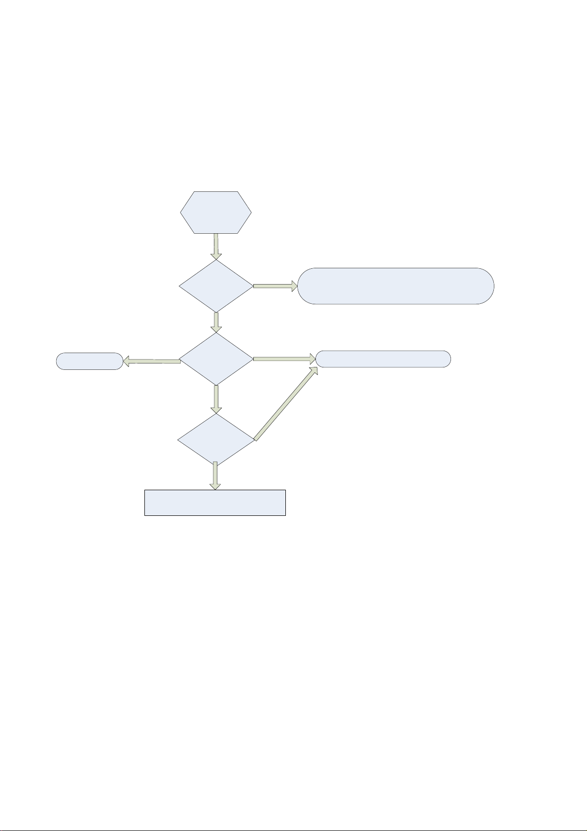
2ǃOnly Backlight, No Video
Reset the
TV set
Y
Check LVDS
cable.
LVDS
Power(P902 PIN
1) is 12V ?
Y
Y
The P902
PIN13,31 clock is
normally?
Y
Check P402
RS232
information
Y
check the setting of Panel resolution(
PC RS232 command)
No in
N
N
ormation
f
1ǃCheck the Q900 and Q901 is Working.
2ǃCheck the LVDS cable connect normally.
Check the U500 working normally.
Appendix 1:How to enter the correct screen parameter through RC?
1ǃInputĀ062598+menu+xxx(Project ID)āon RC, the machine will off and on one time, if you
input the right Project ID, there will be video display.
Page 32

3ǃPicture is normal, but speaker no Audio
Have
picture, no
audio
Y
//LI
KDYHVLJQDO"
Y
&KHFN8SLQ
ˈ
LV9"$QGSLQ
LV9"
Y
&KHFN5LILV9"
Y
I2S signal is right? And
R876\R877\R878\R879 should
be have sign at anytime
N
&KHFNWKHVSHDNHU
DQGFDEOH
&KHFNWKHDXGLR
3RZHUQHW55
N
DQGRWKHUFRPSRQHQWV
DURXQGWKH$XGLR
3RZHUQHW
N
&KHFNLIWKHPXWH
FLUFXLWKDYHDQ\
LVVXH
N
&KHFNLI
R876\R877\R878\R879
have sign at anytime
Y
Check the U700
Page 33

CHECK if the 12V
OUTPUT from U100(L114)
DC-DC CONVERTER CIRCUIT 1
N
1.CHECK if the 24V
INPUT at U100 PIN2?
Y
)$,/85(32,17
N
//LVRSHQFLUFXLW
&&VKRUWFLUFXLW
SRZHUERDUGIDLOXUH
Y
)$,/85(32,17
///LVRSHQFLUFXLW
&&&LVVKRUWFLUFXLW
,&8
2WKHU9QHW
)$,/85(32,17
CHECK if the 1.1V
OUTPUT at U107 (L100)
N
CHECK if the 12V
INPUT at U107
PIN2
N
/LVRSHQFLUFXLW
&&LVVKRUWFLUFXLW
Y
)$,/85(32,17
/LVRSHQFLUFXLW
&&&LVVKRUWFLUFXLW
,&8
2WKHU9&&.9QHW
)$,/85(32,17
CHECK if the 5V
OUTPUT at U1 PIN2,4
CHECK if the 12V
INPUT at U1 PIN3
N
55LVRSHQFLUFXLW
&&LVVKRUWFLUFXLW
Y
)$,/85(32,17
&&LVVKRUWFLUFXLW
,&8
2WKHU781(5B9QHW
Page 34

DC-DC CONVERTER CIRCUIT 2
CHECK if the 5V OUTPUT
from U106+Q100 OUT,L102
Y
CHECK if the DVDD 3V3
OUTPUT at U104 PIN2
N
1.CHECK if the 24V
INPUT at U106
PIN1+Q100 PIN 5?
N
//LVRSHQFLUFXLW
&&LVVKRUWFLUFXLW
)$,/85(32,17
SRZHUERDUGIDLOXUH
Y
)$,/85(32,17
///LVRSHQFLUFXLW
&&LVVKRUWFLUFXLW
,&8
2WKHU9QHW
)$,/85(32,17
NN
CHECK if the 5V
INPUT at U104
PIN3
&LVVKRUWFLUFXLW
Y
)$,/85(32,17
/LVRSHQFLUFXLW
5&&LVVKRUWFLUFXLW
,&8
2WKHU'9''9QHW
CHECK if the
DDRV(1V5) OUTPUT
at U111 PIN2
CHECK if the
AVDD3V3 OUTPUT
at U109 PIN2,4
Y
CHECK if the 5V
INPUT at U111 PIN3
Y
)$,/85(32,17
&&LVVKRUWFLUFXLW
,&8
2WKHU''59QHW
CHECK if the 5V
INPUT at U109 PIN3
Y
)$,/85(32,17
&&LVVKRUWFLUFXLW
,&8
2WKHU$9''9QHW
)$,/85(32,17
NN
55LVRSHQFLUFXLW
&&LVVKRUWFLUFXLW
)$,/85(32,17
NN
&LVVKRUWFLUFXLW
CHECK if the
AVDD1V2 OUTPUT
at U105 PIN2,4
CHECK if the 3.3V
INPUT at U105 PIN3
Y
)$,/85(32,17
5&&LVVKRUWFLUFXLW
,&8
2WKHU$9''9QHW
)$,/85(32,17
NN
55LVRSHQFLUFXLW
&LVVKRUWFLUFXLW
Page 35

LVDS signal output is OK, but Panel is back
Check the P100
PIN12, if is H(3.3V).
N
Check if L118,C163
Q102 and around Q102
is right
Y
U500 issue
Y
N
PSU or LVDS cable and
PANEL issue
Failure from
ADIN3_SRV to L118
Page 36

Key and IR
5&QR
IXQFWLRQ
Y
Check if the P900 PIN2 have
the RC waveform
Y
Check if the IR
net(L920,L926) and cable is
right
Y
U500 issue
.H\QR
IXQFWLRQ
Y
N
P100 PIN1 is 3.3V
Y
Check IR BOARD and RC
N
N
Failure point
Check if the P901 PIN2 value
is variational When you press
the different key button?
Y
Check if R338,L919,
R921,R922,C933 and
cable is right
Y
U500 issue
N
P901 PIN1 is 3.3V
Y
Keyboard issue
N
N
Failure point
Page 37

H4-42C129Z-AGSB0AA
N
R
R
R
R
R
R
R
R
R
R
R
R
R
L42V6200F/MT10B-LA/AUJ/WITHOUT PANEL
parent child description BOM text
H4-42C129Z-AGSB0AA 67-911720-CG01A PRI SUPPORT SIDE AV SUPPORT -- 00 00 00
H4-42C129Z-AGSB0AA 67-911120-0G001 DEC STAND CONNECTER -- 00 00 00 R=N
H4-42C129Z-AGSB0AA 66-890270-3E2 RAW HOLDER SCREW M3×3 -- 00 00 R=Y
H4-42C129Z-AGSB0AA 70-STDV62-EEM1A TV PRI ADDENDUM SHEET V6200 STAND ASSY R
H4-42C129Z-AGSB0AA 72-MT10LA-ELA1A PRI IB MT10L-LA TCL EN R=Y
H4-42C129Z-AGSB0AA 74-008010-12C RAW BAG PE 80MM×100MM (AUTO LOCK) -- 0
H4-42C129Z-AGSB0AA 66-890270-3E2 RAW HOLDER SCREW M3×3 -- 00 00 R=Y
H4-42C129Z-AGSB0AA 66-890270-2E2 RAW HOLDER SCREW M3×2 -- 00 00 R=Y
H4-42C129Z-AGSB0AA 65-Z30050-23MG NUT-HEXAGON 3MM 2.3MM JIS B0209 WHITE ZN
H4-42C129Z-AGSB0AA 65-Z30050-23MG NUT-HEXAGON 3MM 2.3MM JIS B0209 WHITE ZN
H4-42C129Z-AGSB0AA 64-B60200-105G SCREW 6MM 20MM MB-FH 53 R=Y
H4-42C129Z-AGSB0AA 64-B50120-104G SCREW 5MM 12MM 53 R=Y
H4-42C129Z-AGSB0AA 64-B40060-104G MACHINE SCREW
H4-42C129Z-AGSB0AA 64-B30060-105G SCREW 3MM 6MM 53 R=Y
H4-42C129Z-AGSB0AA 64-B30060-104G M/C SCREW B 3 X 6
H4-42C129Z-AGSB0AA 64-B30060-104G M/C SCREW B 3 X 6
H4-42C129Z-AGSB0AA 74-008010-12C RAW BAG PE 80MM×100MM (AUTO LOCK) -- 0
H4-42C129Z-AGSB0AA V6-PROJECT-ID015 SOFTWARE PROJECT ID: 15
H4-42C129Z-AGSB0AA T8-RC300EU-SKY ASS Y - SKD(REMOTE-CONTROL UNIT)ASY FOR REMOTE-CONTROL U
T8-RC300EU-SKY 76-LCDPW1-0AM RAW CARTON-BOX LCD POWER 638MM 341MM X_
T8-RC300EU-SKY 76-LCDPW4-0AA RAW CARTON-BOX LCD POWER 615MM 330MM X_7
H4-42C129Z-AGSB0AA T8-LCDPLAS-SK2 ASS'Y - SKD PACKINGASY FOR PLASTIC SMALL PA
T8-LCDPLAS-SK2 74-120120-50G EPE film FOR PLASTIC SMALL PA
T8-LCDPLAS-SK2 76-001497-0AF CARTON BOX LWH 640X460X360MM FOR PLASTIC SMALL PA
T8-LCDPLAS-SK2 76-346740-01A CARTON SHEET LWH 440X620X3MM FOR PLASTIC SMALL PA
T8-LCDPLAS-SK2 57-343330-000 PLASTIC PLATE FOR PLASTIC SMALL PA
T8-LCDPLAS-SK2 57-600960-0UI PLASTIC PLAE FOR PLASTIC SMALL PA
T8-LCDPLAS-SK2 57-327500-0UI PLASTIC PLATE FOR PLASTIC SMALL PA
T8-LCDPLAS-SK2 57-327460-0UI TV RAW FASTENER L-24 DISK -- 00 00 R=N FOR PLASTIC SMALL PA
T8-LCDPLAS-SK2 57-312490-0UIG TV RAW FASTENER(plastic sucker)70pcs 34* FOR PLASTIC SMALL PA
T8-LCDPLAS-SK2 57-605000-0UIG TV RAW FASTENER 6格吸塑盘385*73*78 -- 01 FOR PLASTIC SMALL PA
T8-LCDPLAS-SK2 74-036052-40C POLYBAG FOR PLASTIC SMALL PA
T8-LCDPLAS-SK2 57-327490-0UIG TV RAW FASTENER 12格吸塑盘252*54*30 -- 0 FOR PLASTIC SMALL PA
T8-LCDPLAS-SK2 57-408100-0HNG TV RAW FASTENER(plastic sucker)12pcs 184 FOR PLASTIC SMALL PA
H4-42C129Z-AGSB0AA T8-KEYBR01-SK2 ASS'Y-SKD PACKING(KEY BRACKET) FOR KEY BR
T8-KEYBR01-SK2 57-327460-0UIG TV RAW FASTENER(plastic sucker)24pcs 150
T8-KEYBR01-SK2 74-120120-50G EPE film
T8-KEYBR01-SK2 76-001497-0AF CARTON BOX LWH 640X460X360MM
T8-KEYBR01-SK2 76-346740-01A CARTON SHEET LWH 440X620X3MM
H4-42C129Z-AGSB0AA T8-42S12RC-SK1 ASS'Y-SKD PACKING(R CAB.) FOR R CAB
T8-42S12RC-SK1 77-130100-6WC Bubble Bag FOR F CAB.
T8-42S12RC-SK1 76-925130-0AR RAW CARTON-BOX RC 1032MM 417MM 673MM CA FOR R CAB.
T8-42S12RC-SK1 74-130100-80G Poly Bag FOR R CAB.
T8-42S12RC-SK1 76-925150-0AA RAW CARTON-BOX RC 800MM 458MM 78MM CA 00 FOR RC.
T8-42S12RC-SK1 74-113038-5PG RAW CUSHION EPE SHEET LED46P21 FC 1135M FOR TOP & BOTTOM
H4-42C129Z-AGSB0AA T8-42C12FC-SK1 ASS'Y-SKD PACKING(F CAB.) FOR F CAB
T8-42C12FC-SK1 74-120110-50QSW PLASTIC BAG
T8-42C12FC-SK1 74-130100-80G Poly Bag
T8-42C12FC-SK1 76-925140-0AF RAW CARTON-BOX FC 1043MM 425MM 685MM CA
T8-42C12FC-SK1 76-LS1201-0AA RAW CARTON TCL LED42S12 482MM 560MM 60MM
H4-42C129Z-AGSB0AA 89-BX8915-JZ0U SUNDRIES-TAPE ADHESIVE 18MMX55M -- 3M胶带,固定线材
H4-42C129Z-AGSB0AA 76-915720-0AT RAW CARTON-BOX LED42D20 1179MM 179MM 781
H4-42C129Z-AGSB0AA 75-915710-EC0 RAW POLYFOAM BOTTOM MIDDLE LCD42D20-EM H4-42C129Z-AGSB0AA 75-915700-EC0 RAW POLYFOAM BOTTOM RIGHT LCD42D20-EM --
Page 38

H4-42C129Z-AGSB0AA 75-915690-EC0 RAW POLYFOAM BOTTOM LEFT LCD42D20-EM --
K
R
A
L
K
E
A
A
A
H4-42C129Z-AGSB0AA 75-915680-EC0 RAW POLYFOAM TOP MIDDLE LCD42D20-EM -- 0
H4-42C129Z-AGSB0AA 75-915670-EC0 RAW POLYFOAM TOP RIGHT LCD42D20-EM -- 00
H4-42C129Z-AGSB0AA 75-915660-EC0 RAW POLYFOAM TOP LEFT LCD42D20-EM -- 00
H4-42C129Z-AGSB0AA 74-135105-50HEM DEC BAG -- R=N
H4-42C129Z-AGSB0AA 74-022032-5WEEM DEC BAG -- R=Y
H4-42C129Z-AGSB0AA 64-B30060-104G M/C SCREW B 3 X 6 固定电源插座支撑到屏
H4-42C129Z-AGSB0AA 51-DC0180-12R0FG POWER CORD 1800MM Y GL0804191 PA
H4-42C129Z-AGSB0AA 49-911100-GLS01C
DEC STAND GLASS -- 00 01 00 R=E
H4-42C129Z-AGSB0AA 47-PWS041-LX2 SOCKET ST N DLK CDJ-8D-VHL250
H4-42C129Z-AGSB0AA 46-LL030L-12X02G WIRE FOR POWER 300MM 12 PHD PHD 2.0MM UL FROM MB P100 TO POWE
H4-42C129Z-AGSB0AA 46-FM080L-04P01G KEY WIRE 800MM 4 A2008 A1250/1255 2.0 FROM MB P901 TO KEYP
H4-42C129Z-AGSB0AA 46-FM060L-07P01G IR WIRE 600MM 7 A200 FROM MB P900 TO IR
H4-42C129Z-AGSB0AA 46-FB500L-LGXL2G WIRE LVDS WIRE 500MM 51 FI-RE51HL PHDR-4 FROM MB P902 TO PANE
H4-42C129Z-AGSB0AA 46-CN065L-04A02G WIRE FROM MB TO SPEAKER 650/250MM 4 TJC3 FROM MB P801 TO SPEA
H4-42C129Z-AGSB0AA 46-CF040L-14V01G WIRE INVERTER CABLE 400MM 14PIN TJC3 PH FROM POWER TO INVERT
H4-42C129Z-AGSB0AA 41-UK0150-0KK02 WIRE 2.6MM 0D2.6/7.8(9/0.10BC+S25/0.10BC FOR P304 P499 P498
H4-42C129Z-AGSB0AA 41-UK0150-0KK01 WIRE 2.6MM 0D2.6/7.8(9/0.10BC+S25/0.10BC FOR P1
H4-42C129Z-AGSB0AA 41-40398H-02X WIRE 3.2MM UL#AWG/1C(7/0.12TS) 150MM FOR P455
H4-42C129Z-AGSB0AA 08-RC3000M-RM202
ASS'Y - RC300-EM/ANALOG TV
08-RC3000M-RM202AA 12-C81725-0BX TR-SMD NPN 45VV 500MA_A 100MHZ 0.25W SOT Q1
08-RC3000M-RM202AA 13-AS1228-32B IC 32FS6646 INFRARED RC IC 散装 SOP20 AS U1
08-RC3000M-RM202AA 14-IRE05B-XX1 LED 1.4V 0.1_A WHM TRANSPARENT 36 AT205B D1
08-RC3000M-RM202AA 19-AB0101-JTX RES SMD 100 OHM 1/10W 0603 R2
08-RC3000M-RM202AA 19-CD0229-JTX SMD. RES 2.2 OHM 1/4W +/-5% 1206 R1
08-RC3000M-RM202AA 25-HCL470-M1X CAP.ELE 2MM 47UF 16VV 5*7 85 \ C1
08-RC3000M-RM202AA 45-COS4M0-0Y1 RESONATOR 4MHZ 6_V 30OHM BULK X1
08-RC3000M-RM202AA 49-895610-0001E TV DEC RUBBER KEYBOARD RC300 -- 00 -- 00 FOR FRONT CAB
08-RC3000M-RM202AA 57-894200-0HA1A PAI DOOR RC300 BATTERY -- 00 -- 00 R=Y
08-RC3000M-RM202AA 57-894210-0HU1E DEC CABINET FRONT RC300 -- 00 -- 00 R=Y
08-RC3000M-RM202AA 57-894220-0HA1A PAI COVER RC300 BACK -- 00 -- 00 R=Y
08-RC3000M-RM202AA 67-X89557-0E0 TV RAW SPRING RC200 BATTERY-Z 00 00 R=Y FOR PCB
08-RC3000M-RM202AA 67-X89558-0E0 TV RAW SPRING RC200 BATTERY -F 00 00 R=Y FOR PCB
08-RC3000M-RM202AA 67-X89559-0E0 TV RAW SPRING RC200 BATTERY -ZF 00 00 R= FOR BACK CAB
08-RC3000M-RM202AA 71-REMOTE-NUL1A PRI LABEL REMOTE -- R=Y
08-RC3000M-RM202AA 74-007026-60CR POLYBAG (70MMX260MMX0.06MM)
08-RC3000M-RM202AA 40-LARC30-RMA1XG TV PCB RM BD R=Y
H4-42C129Z-AGSB0AA 08-PE461C2-PW200
08-PE461C2-PW200AA 08-PE461C2-PW300
ASS'Y - POWER BD
ASS'Y - POWER BD
08-PE461C2-PW300AA 41-WJ0125-B00 WIREBAREJUMPER12.5MM J23
08-PE461C2-PW300AA 41-WJ0125-B00 WIREBAREJUMPER12.5MM J14
08-PE461C2-PW300AA 41-WJ0125-B00 WIREBAREJUMPER12.5MM J27
08-PE461C2-PW300AA 41-WJ0125-B00 WIREBAREJUMPER12.5MM J34
08-PE461C2-PW300AA 41-WJ0130-B00 WIREBAREJUMPER13MM J36
08-PE461C2-PW300AA 41-WJ0150-B00 WIREBAREJUMPER15MM J16
08-PE461C2-PW300AA 41-WJ0150-B00 WIREBAREJUMPER15MM J8
08-PE461C2-PW300AA 41-WJ0150-B00 WIREBAREJUMPER15MM J15
08-PE461C2-PW300AA 41-WJ0175-B00 WIREBAREJUMPER17.5MM J2
08-PE461C2-PW300AA 41-WJ0175-B00 WIREBAREJUMPER17.5MM J5
08-PE461C2-PW300AA 41-WJ0175-B00 WIREBAREJUMPER17.5MM J7
08-PE461C2-PW300AA 41-WJ0175-B00 WIREBAREJUMPER17.5MM J17
08-PE461C2-PW300AA 41-WJ0175-B00 WIREBAREJUMPER17.5MM J10
08-PE461C2-PW300AA 41-WJ0060-B00 WIRE-BARE J43
08-PE461C2-PW300AA 41-WJ0075-B00 WIREBAREJUMPER7.5MM J41
08-PE461C2-PW300AA 41-WJ0075-B00 WIREBAREJUMPER7.5MM J11
08-PE461C2-PW300AA 41-WJ0075-B00 WIREBAREJUMPER7.5MM J1
08-PE461C2-PW300AA 41-WJ0095-B00 WIREBAREJUMPER9.5MM J32
08-PE461C2-PW300AA 41-WJ0095-B00 WIREBAREJUMPER9.5MM J13
08-PE461C2-PW300AA 41-WJ0095-B00 WIREBAREJUMPER9.5MM J12
08-PE461C2-PW300AA 41-WJ0100-B00 WIREBAREJUMPER10MM J25
Page 39

08-PE461C2-PW300AA 41-WJ0100-B00 WIREBAREJUMPER10MM J39
A
08-PE461C2-PW300AA 41-WJ0110-B00 WIREBAREJUMPER11MM J19
08-PE461C2-PW300AA 41-WJ0110-B00 WIREBAREJUMPER11MM J9
08-PE461C2-PW300AA 41-WJ0110-B00 WIREBAREJUMPER11MM J20
08-PE461C2-PW300AA 41-WJ0125-B00 WIREBAREJUMPER12.5MM J24
08-PE461C2-PW300AA 64-Z30080-114G Screws FOR DS3
08-PE461C2-PW300AA 64-Z30080-114G Screws FOR DS2
08-PE461C2-PW300AA 64-Z30080-114G Screws FOR QW3
08-PE461C2-PW300AA 64-Z30080-114G Screws FOR QW1
08-PE461C2-PW300AA 64-Z30100-112G MACHINE SCREW FOR BD1
08-PE461C2-PW300AA 66-20516X-1B0 RAW HOLDER FUSE -- 01 00 R=Y FOR F1
08-PE461C2-PW300AA 67-H88490-6A0 RAW HEATSINK FOR ALL 06 00 R=Y Y2
08-PE461C2-PW300AA 67-H88490-7A0 RAW HEATSINK FOR ALL 07 00 R=Y Y3
08-PE461C2-PW300AA 67-H88490-8A0 RAW HEATSINK FOR ALL 08 00 R=Y Y1
08-PE461C2-PW300AA 67-M60442-1E0 TV RAW SPRING GND-15 00 01 R=Y G2
08-PE461C2-PW300AA 67-M60442-1E0 TV RAW SPRING GND-15 00 01 R=Y G5
08-PE461C2-PW300AA 67-M60442-1E0 TV RAW SPRING GND-15 00 01 R=Y G7
08-PE461C2-PW300AA 67-M60442-1E0 TV RAW SPRING GND-15 00 01 R=Y G1
08-PE461C2-PW300AA 41-WJ0175-B00 WIREBAREJUMPER17.5MM J4
08-PE461C2-PW300AA 41-WJ0200-B00 WIREBAREJUMPER20MM J26
08-PE461C2-PW300AA 41-WJ0200-B00 WIREBAREJUMPER20MM J37
08-PE461C2-PW300AA 46-39219W-03XG PIN BASE VH-3AW CN1
08-PE461C2-PW300AA 46-40337W-14XG CONN PHD 14 2.5MM MALE WHITE R P2
08-PE461C2-PW300AA 46-40338W-12XG CONN PHD 12 2.0MM FEMALE R P1
08-PE461C2-PW300AA 50-05000D-6GS3G FUSE 5A 250V F1
08-PE461C2-PW300AA 57-893390-0UG RAW HOLDER SPACE -- 00 00 R=Y K4
08-PE461C2-PW300AA 57-893390-0UG RAW HOLDER SPACE -- 00 00 R=Y K2
08-PE461C2-PW300AA 57-893390-0UG RAW HOLDER SPACE -- 00 00 R=Y K1
08-PE461C2-PW300AA 57-893390-0UG RAW HOLDER SPACE -- 00 00 R=Y K5
08-PE461C2-PW300AA 57-893390-0UG RAW HOLDER SPACE -- 00 00 R=Y K3
08-PE461C2-PW300AA 64-Z30080-114G Screws FOR QW2
08-PE461C2-PW300AA 18-CF0334-JGXL RESISTOR RESISTOR 330KOHM 5% 1W 69058 R205
08-PE461C2-PW300AA 18-RF0108-JGXL RESISTOR RESISTOR 0.1OHM 5% 1W KN1W R309
08-PE461C2-PW300AA 22-NTC309-XX1 NTC.RES 3D2-14 RN1
08-PE461C2-PW300AA 22-VDR561-XG3 VDR 460V 2500A Y 14D561K-W RV1
08-PE461C2-PW300AA 25-GCB221-M1X CAP.ELE 5MM 220UF 16VV 6.3*11 105 \ C210
08-PE461C2-PW300AA 25-GEF471-M1X CAP.ELE 5MM 470UF 35V 10 105 CD263 C413
08-PE461C2-PW300AA 25-GNF470-M1S CAP.ELE 105DEGREE C 47UF 20% 450V 500MA CE2
08-PE461C2-PW300AA 25-GNF470-M1S CAP.ELE 105DEGREE C 47UF 20% 450V 500MA CE3
08-PE461C2-PW300AA 25-GNF470-M1S CAP.ELE 105DEGREE C 47UF 20% 450V 500MA CE1
08-PE461C2-PW300AA 25-GNF689-M1W CAP.ELE 5MM 6.8UF 450V 10*20 105 KM450V6 CE4
08-PE461C2-PW300AA 25-NEF102-M1S CAP.ELE 105DEGREE C 1000UF 20% 35V 2560M C411
08-PE461C2-PW300AA 25-NEF102-M1S CAP.ELE 105DEGREE C 1000UF 20% 35V 2560M C412
08-PE461C2-PW300AA 08-PE461C2-PW3AI
ASS'Y - POWER BD(AI PARTS)
08-PE461C2-PW3AIAA 26-AKC101-KRX CAP.CER 100P0F 1K0V - C314
08-PE461C2-PW3AIAA 26-AKC221-KRX CAP.CER 220P0F 1K0V - C405
08-PE461C2-PW3AIAA 26-AKC221-KRX CAP.CER 220P0F 1K0V - C310
08-PE461C2-PW3AIAA 26-AKC221-KRX CAP.CER 220P0F 1K0V - C201
08-PE461C2-PW3AIAA 27-MGC683-J0B FILM CAPACITOR 68NF 5MM 250V CL23B 5% C315
08-PE461C2-PW3AIAA 66-343730-0B0 HOLLOW RIVET 1.6MMX3.0MMX3.2MM FOR RV1
08-PE461C2-PW3AIAA 66-343730-0B0 HOLLOW RIVET 1.6MMX3.0MMX3.2MM FOR LF2
08-PE461C2-PW3AIAA 66-343730-0B0 HOLLOW RIVET 1.6MMX3.0MMX3.2MM FOR TS2
08-PE461C2-PW3AIAA 66-343730-0B0 HOLLOW RIVET 1.6MMX3.0MMX3.2MM FOR C101
08-PE461C2-PW3AIAA 66-343730-0B0 HOLLOW RIVET 1.6MMX3.0MMX3.2MM FOR LF3
08-PE461C2-PW3AIAA 66-343730-0B0 HOLLOW RIVET 1.6MMX3.0MMX3.2MM FOR C406
08-PE461C2-PW3AIAA 66-343730-0B0 HOLLOW RIVET 1.6MMX3.0MMX3.2MM FOR BD1
08-PE461C2-PW3AIAA 66-343740-0B0 HOLLOW RIVET (2.3MMX4.0MMX3.5MM) FOR CN1
08-PE461C2-PW3AIAA 10-0001H8-FBX DIODE 1H8 (FAST RECOVERY) D201
08-PE461C2-PW3AIAA 10-0FR104-FBX DIODE FR104 (FAST RECTIFIER) D206
08-PE461C2-PW3AIAA 10-0FR104-FBX DIODE FR104 (FAST RECTIFIER) D204
Page 40

08-PE461C2-PW3AIAA 10-0RL255-EBX D-PIN 1.1V 2_A 800V / /W DO-15 RL255 D304
A
08-PE461C2-PW3AIAA 10-0RL255-EBX D-PIN 1.1V 2_A 800V / /W DO-15 RL255 D303
08-PE461C2-PW3AIAA 10-0SR160-SBX D-PIN 0.7VV 1_A 60VV / /W DO-41 SR160 DS1
08-PE461C2-PW3AIAA 10-1N4007-EBX DIODE 1N4007 D202
08-PE461C2-PW3AIAA 10-MUR160-FBX VLTRAFAST PLASTIC REITFIER MUR160 D401
08-PE461C2-PW3AIAA 13-000TL4-31T IC-REGSPECKT TL431ACLP R=N U402
08-PE461C2-PW3AIAA 13-AZ431L-E1T IC SECOND EXPLOITATION VOLTAGE ADJUSTER U202
08-PE461C2-PW3AIAA 25-TFB220-M1X CAP.ELE 5MM 22UF 50V 6.3 * 7 105 CD70H C206
08-PE461C2-PW3AIAA 25-TFB220-M1X CAP.ELE 5MM 22UF 50V 6.3 * 7 105 CD70H C219
08-PE461C2-PW3AIAA 25-TFB220-M1X CAP.ELE 5MM 22UF 50V 6.3 * 7 105 CD70H C204
08-PE461C2-PW300AA 08-PE461C2-PW3ST
ASS'Y - POWER BD(SMT PARTS)
08-PE461C2-PW3STAA 19-CD0479-JTX SMD.RES 4.7 OHM 1/4W +/-5% R408
08-PE461C2-PW3STAA 19-CD0479-JTX SMD.RES 4.7 OHM 1/4W +/-5% R201
08-PE461C2-PW3STAA 19-CD0472-JTX SMD. RES 4.7K OHM 1/4W 5% R446
08-PE461C2-PW3STAA 19-CD0472-JTX SMD. RES 4.7K OHM 1/4W 5% R445
08-PE461C2-PW3STAA 19-CD0472-JTX SMD. RES 4.7K OHM 1/4W 5% R423
08-PE461C2-PW3STAA 19-CD0472-JTX SMD. RES 4.7K OHM 1/4W 5% R424
08-PE461C2-PW3STAA 19-CD0273-JTX SMD. RES 27K OHM 1/4W +/-5% 1206 R415
08-PE461C2-PW3STAA 19-CD0273-JTX SMD. RES 27K OHM 1/4W +/-5% 1206 R416
08-PE461C2-PW3STAA 19-CD0479-JTX SMD.RES 4.7 OHM 1/4W +/-5% R405
08-PE461C2-PW3STAA 19-CD0479-JTX SMD.RES 4.7 OHM 1/4W +/-5% R206
08-PE461C2-PW3STAA 19-CD0479-JTX SMD.RES 4.7 OHM 1/4W +/-5% R301
08-PE461C2-PW3STAA 19-CD0479-JTX SMD.RES 4.7 OHM 1/4W +/-5% R202
08-PE461C2-PW3STAA 19-CD0479-JTX SMD.RES 4.7 OHM 1/4W +/-5% R211
08-PE461C2-PW3STAA 19-CD0479-JTX SMD.RES 4.7 OHM 1/4W +/-5% R406
08-PE461C2-PW3STAA 19-CD0479-JTX SMD.RES 4.7 OHM 1/4W +/-5% R227
08-PE461C2-PW3STAA 19-CD0105-FTX SMD.RES 1M OHM 1/4W +/-1% 1206 R402
08-PE461C2-PW3STAA 19-CD0105-FTX SMD.RES 1M OHM 1/4W +/-1% 1206 R403
08-PE461C2-PW3STAA 19-CD0109-JTX SMD.RES 1 OHM 1/4W +/-5% R310
08-PE461C2-PW3STAA 19-CD0109-JTX SMD.RES 1 OHM 1/4W +/-5% R311
08-PE461C2-PW3STAA 19-CD0109-JTX SMD.RES 1 OHM 1/4W +/-5% R312
08-PE461C2-PW3STAA 19-CD0202-JTX SMD. RES 2K OHM 1/4W +/-5% R218
08-PE461C2-PW3STAA 19-CD0205-FTX SMD.RES 2M OHM 1206 +/-1% RD7
08-PE461C2-PW3STAA 19-CD0205-FTX SMD.RES 2M OHM 1206 +/-1% RD3
08-PE461C2-PW3STAA 19-CD0205-FTX SMD.RES 2M OHM 1206 +/-1% RD8
08-PE461C2-PW3STAA 19-CD0205-FTX SMD.RES 2M OHM 1206 +/-1% RD2
08-PE461C2-PW3STAA 19-CD0205-FTX SMD.RES 2M OHM 1206 +/-1% RD1
08-PE461C2-PW3STAA 19-CD0205-FTX SMD.RES 2M OHM 1206 +/-1% RD6
08-PE461C2-PW3STAA 19-CD0205-FTX SMD.RES 2M OHM 1206 +/-1% RD5
08-PE461C2-PW3STAA 19-CD0205-FTX SMD.RES 2M OHM 1206 +/-1% RD4
08-PE461C2-PW3STAA 19-CD0220-JTX SMD. RES 22 OHM 1/4W +/-5% 1206 R409
08-PE461C2-PW3STAA 19-CD0222-JTX RES.SMD 2.2K OHM 1/4W 5% R412
08-PE461C2-PW3STAA 28-BB0104-ZFX CAP.CER,SMD 100N0F 50V DCV 0805 - C215
08-PE461C2-PW3STAA 28-BB0224-KBX CAP.CER,SMD 220N0F 50V DCV 0805 - C416
08-PE461C2-PW3STAA 28-BB0224-KBX CAP.CER,SMD 220N0F 50V DCV 0805 - C415
08-PE461C2-PW3STAA 28-BB0473-KBX CAP.CER,SMD 47N0F 50.0V 0805 - C202
08-PE461C2-PW3STAA 28-BB0474-ZFX CAP.CER,SMD 470N0F 50V DCV 0805 - C302
08-PE461C2-PW3STAA 28-BD0105-KBX CAP.CER,SMD 1U0F 25V DCV 0805 - C425
08-PE461C2-PW3STAA 28-BD0105-KBX CAP.CER,SMD 1U0F 25V DCV 0805 - C308
08-PE461C2-PW3STAA 28-BD0105-KBX CAP.CER,SMD 1U0F 25V DCV 0805 - C218
08-PE461C2-PW3STAA 28-BD0105-KBX CAP.CER,SMD 1U0F 25V DCV 0805 - C309
08-PE461C2-PW3STAA 28-BD0105-KBX CAP.CER,SMD 1U0F 25V DCV 0805 - C212
08-PE461C2-PW3STAA 28-BD0105-KBX CAP.CER,SMD 1U0F 25V DCV 0805 - C421
08-PE461C2-PW3STAA 28-BD0225-ZFX CAP.CER,SMD 2U2F 25V DCV 0805 - C402
08-PE461C2-PW3STAA 28-BD0225-ZFX CAP.CER,SMD 2U2F 25V DCV 0805 - C403
08-PE461C2-PW3STAA 28-CB0105-KBX CAP.CER,SMD 1U0F 50.0V 1206 - C420
08-PE461C2-PW3STAA 28-CB0105-KBX CAP.CER,SMD 1U0F 50.0V 1206 - C414
08-PE461C2-PW3STAA 28-CB0105-KBX CAP.CER,SMD 1U0F 50.0V 1206 - C211
08-PE461C2-PW3STAA 19-CD0624-FTX SMD.RES 620k OHM 1/4W +/-1% R303
08-PE461C2-PW3STAA 19-CD0624-FTX SMD.RES 620k OHM 1/4W +/-1% R304
Page 41

08-PE461C2-PW3STAA 28-BA0475-KBX CAP.CER,SMD 4U7F 10V DCV 0805 188605656 C417
08-PE461C2-PW3STAA 28-BA0475-KBX CAP.CER,SMD 4U7F 10V DCV 0805 188605656 C418
08-PE461C2-PW3STAA 28-BA0475-KBX CAP.CER,SMD 4U7F 10V DCV 0805 188605656 C408
08-PE461C2-PW3STAA 28-BA0475-KBX CAP.CER,SMD 4U7F 10V DCV 0805 188605656 C424
08-PE461C2-PW3STAA 28-BB0101-JCX SMD CAP. 100 PF 50V C 0805 C410
08-PE461C2-PW3STAA 28-BB0102-KBX CAP.CER,SMD 1NF 50.0V 0805 - +/-10% R=Y C306
08-PE461C2-PW3STAA 28-BB0102-KBX CAP.CER,SMD 1NF 50.0V 0805 - +/-10% R=Y C409
08-PE461C2-PW3STAA 28-BB0102-KBX CAP.CER,SMD 1NF 50.0V 0805 - +/-10% R=Y C305
08-PE461C2-PW3STAA 28-BB0102-KBX CAP.CER,SMD 1NF 50.0V 0805 - +/-10% R=Y C304
08-PE461C2-PW3STAA 28-BB0102-KBX CAP.CER,SMD 1NF 50.0V 0805 - +/-10% R=Y C407
08-PE461C2-PW3STAA 28-BB0103-KBX CAP.CER,SMD 10NF 50.0V 0805 - +/-10% R=Y C217
08-PE461C2-PW3STAA 28-BB0104-KBX CAP.CER,SMD 100N0F 50V DCV 0805 - C303
08-PE461C2-PW3STAA 28-BB0104-ZFX CAP.CER,SMD 100N0F 50V DCV 0805 - C419
08-PE461C2-PW3STAA 28-BB0104-ZFX CAP.CER,SMD 100N0F 50V DCV 0805 - C401
08-PE461C2-PW3STAA 19-CD0105-FTX SMD.RES 1M OHM 1/4W +/-1% 1206 R401
08-PE461C2-PW3STAA 19-BC0100-JTX SMD. RES 10 OHM 1/8W +/-5% R417
08-PE461C2-PW3STAA 19-BC0100-JTX SMD. RES 10 OHM 1/8W +/-5% R420
08-PE461C2-PW3STAA 19-BC0101-JTX SMD.RES100 OHM 1/8W +/-5% R207
08-PE461C2-PW3STAA 19-BC0102-JTX SMD.RES 1K OHM 1/8W +/-5% R407
08-PE461C2-PW3STAA 19-BC0102-JTX SMD.RES 1K OHM 1/8W +/-5% R228
08-PE461C2-PW3STAA 19-BC0102-JTX SMD.RES 1K OHM 1/8W +/-5% R440
08-PE461C2-PW3STAA 19-BC0103-JTX SMD. RES 10K OHM 1/8W +/-5% R422
08-PE461C2-PW3STAA 19-BC0103-JTX SMD. RES 10K OHM 1/8W +/-5% R229
08-PE461C2-PW3STAA 19-BC0103-JTX SMD. RES 10K OHM 1/8W +/-5% R427
08-PE461C2-PW3STAA 19-BC0103-JTX SMD. RES 10K OHM 1/8W +/-5% R419
08-PE461C2-PW3STAA 19-BC0103-JTX SMD. RES 10K OHM 1/8W +/-5% R319
08-PE461C2-PW3STAA 19-BC0103-JTX SMD. RES 10K OHM 1/8W +/-5% R435
08-PE461C2-PW3STAA 19-BC0104-JTX SMD.RES 0805,1/8W,±5%,100KΩ R439
08-PE461C2-PW3STAA 19-BC0104-JTX SMD.RES 0805,1/8W,±5%,100KΩ R404
08-PE461C2-PW3STAA 19-BC0104-JTX SMD.RES 0805,1/8W,±5%,100KΩ R443
08-PE461C2-PW3STAA 09-0BAS21-ATX DIO SIG SM BAS21 D207
08-PE461C2-PW3STAA 09-0BAV70-ATX D,SMD 75VV 125MA_A 715MVV 4N 0.25W SOT23 D402
08-PE461C2-PW3STAA 09-0BAV70-ATX D,SMD 75VV 125MA_A 715MVV 4N 0.25W SOT23 D209
08-PE461C2-PW3STAA 09-0BAV70-ATX D,SMD 75VV 125MA_A 715MVV 4N 0.25W SOT23 D403
08-PE461C2-PW3STAA 09-0BAV70-ATX D,SMD 75VV 125MA_A 715MVV 4N 0.25W SOT23 D302
08-PE461C2-PW3STAA 09-0BAV99-ATX D,SMD 70.0V 200MI0_A 855MI0V 4N 0.25W SO D404
08-PE461C2-PW3STAA 09-52HC15-DTX D-ZENER, SMD 15V /A 0.375W BZT52HC15 D208
08-PE461C2-PW3STAA 09-52HC18-DTX D-ZENER, SMD 18V /A 0.375W BZT52HC18 D205
08-PE461C2-PW3STAA 09-55C15V-DTX SMD.DIODE BZV55-C15 D203
08-PE461C2-PW3STAA 09-55C15V-DTX SMD.DIODE BZV55-C15 D405
08-PE461C2-PW3STAA 09-55C33V-DTX SMD.DIODE BZV55-C33 D210
08-PE461C2-PW3STAA 12-BT3904-0BX TR-SMD NPN 40VV 200MA_A 300HZ 0.25W SOT2 Q401
08-PE461C2-PW3STAA 12-S4160T-0BX TR-SMD NPN 60VV 1A_A 220MHZ 0.27W SOT23 Q202
08-PE461C2-PW3STAA 13-NCP139-7AB IC PE121C0 POWER MANAGEMENT IC TAPE & RE U401
08-PE461C2-PW3STAA 13-NCP160-7BB IC PWL4222 PFC IC TAPE & REEL SO-8 NCP16 U301
08-PE461C2-PW3STAA 19-BC0000-JTX SMD.RES 0 OHM 1/8W +/-5% J21
08-PE461C2-PW3STAA 19-BC0393-FTX SMD.RES 39K OHM 1/8W +/-1% R429
08-PE461C2-PW3STAA 19-BC0393-JTX SMD.RES 39K OHM 1/8W +/-5% R326
08-PE461C2-PW3STAA 19-BC0393-JTX SMD.RES 39K OHM 1/8W +/-5% R436
08-PE461C2-PW3STAA 19-BC0470-JTX SMD.RES 0805,1/8W,±5%,47Ω R222
08-PE461C2-PW3STAA 19-BC0470-JTX SMD.RES 0805,1/8W,±5%,47Ω R318
08-PE461C2-PW3STAA 19-BC0471-FTX SMD.RES 0805,1/8W,±1%,470Ω R431
08-PE461C2-PW3STAA 19-BC0472-JTX SMD. RES 4.7K OHM 1/8W +/-5% R411
08-PE461C2-PW3STAA 19-BC0472-JTX SMD. RES 4.7K OHM 1/8W +/-5% R217
08-PE461C2-PW3STAA 19-BC0472-JTX SMD. RES 4.7K OHM 1/8W +/-5% R425
08-PE461C2-PW3STAA 19-BC0474-JTX SMD.RES 0805,1/8W,±5%,470KΩ R441
08-PE461C2-PW3STAA 19-BC0562-JTX SMD.RES 0805,1/8W,±5%,5.6KΩ R438
08-PE461C2-PW3STAA 19-BC0563-FTX SMD.RES 0805,1/8W,±1%,56KΩ R219
08-PE461C2-PW3STAA 19-BC0681-FTX SMD.RES 0805,1/8W,±1%,680Ω R307
08-PE461C2-PW3STAA 19-CD0000-JTX RES.SMD 0 OHM 1206 J3
Page 42

08-PE461C2-PW3STAA 19-CD0105-FTX SMD.RES 1M OHM 1/4W +/-1% 1206 R302
08-PE461C2-PW3STAA 19-CD0105-FTX SMD.RES 1M OHM 1/4W +/-1% 1206 R305
08-PE461C2-PW3STAA 19-BC0122-FTX SMD. RES 1.2K OHM 1/8W +/-1% R426
08-PE461C2-PW3STAA 19-BC0122-FTX SMD. RES 1.2K OHM 1/8W +/-1% R216
08-PE461C2-PW3STAA 19-BC0122-FTX SMD. RES 1.2K OHM 1/8W +/-1% R220
08-PE461C2-PW3STAA 19-BC0183-FTX SMD.RES 0805,1/8W,±1%,18KΩ R428
08-PE461C2-PW3STAA 19-BC0203-FTX SMD.RES 0805,1/8W,±1%,20KΩ R306
08-PE461C2-PW3STAA 19-BC0220-JTX SMD.RES 0805,1/8W,±5%,22Ω R317
08-PE461C2-PW3STAA 19-BC0222-FTX SMD. RES 2.2K OHM 1/8W +/-1% R430
08-PE461C2-PW3STAA 19-BC0222-FTX SMD. RES 2.2K OHM 1/8W +/-1% R442
08-PE461C2-PW3STAA 19-BC0223-FTX SMD. RES 22K OHM 1/8W +/-1% R437
08-PE461C2-PW3STAA 19-BC0303-FTX SMD.RES 0805,1/8W,±1%,30KΩ R433
08-PE461C2-PW3STAA 19-BC0330-JTX SMD.RES 0805,1/8W,±5%,33Ω R418
08-PE461C2-PW3STAA 19-BC0330-JTX SMD.RES 0805,1/8W,±5%,33Ω R421
08-PE461C2-PW3STAA 19-BC0332-JTX SMD.RES 3.3K OHM 1/8W +/-5% R323
08-PE461C2-PW3STAA 19-BC0332-JTX SMD.RES 3.3K OHM 1/8W +/-5% R432
08-PE461C2-PW3STAA 19-BC0333-FTX SMD. RES 33K OHM 1/8W +/-1% R308
08-PE461C2-PW3STAA 19-BC0333-FTX SMD. RES 33K OHM 1/8W +/-1% R210
08-PE461C2-PW3STAA 19-BC0154-JTX SMD.RES 0805,1/8W,±5%,150KΩ R209
08-PE461C2-PW3STAA 19-CD0824-FTX SMD.RES 820k OHM 1/4W +/-1% R208
08-PE461C2-PW300AA 10-20100T-SNX D-PIN 0.8V 20_A 100V 20N 16W ITO-220S MB DS2
08-PE461C2-PW300AA 10-20100T-SNX D-PIN 0.8V 20_A 100V 20N 16W ITO-220S MB DS3
08-PE461C2-PW300AA 10-MUR460-FB6 ULTRAFAST PLASTIC RECTIFIER MUR460 D301
08-PE461C2-PW300AA 10-US15KB-H7X D-PIN 1.1V 15_A 800V / /W SIP US15KB80R BD1
08-PE461C2-PW300AA 11-DF12N5-0CX MOSFET N 500V 12A 30V 0.65OHM 42W MDF12N QW2
08-PE461C2-PW300AA 11-DF12N5-0CX MOSFET N 500V 12A 30V 0.65OHM 42W MDF12N QW1
08-PE461C2-PW300AA 11-DF12N5-0CX MOSFET N 500V 12A 30V 0.65OHM 42W MDF12N QW3
08-PE461C2-PW300AA 13-TCP781-D4P OPTICOUP 80V TLP781F PC1
08-PE461C2-PW300AA 13-TCP781-D4P OPTICOUP 80V TLP781F PC2
08-PE461C2-PW300AA 13-TCP781-D4P OPTICOUP 80V TLP781F PC3
08-PE461C2-PW300AA 13-VIPER1-7LP IC-PS POWER IC VIPER17LN R=N U201
08-PE461C2-PW300AA 36-LIF197-BX0 COILS AND INDUCTORS 230UH 500V PFC INDUC LP1
08-PE461C2-PW300AA 36-LIF212-BX0 COILS AND INDUCTORS 200UH 1500V FILTER 1 LF1
08-PE461C2-PW300AA 36-TRF360-LX0 TRANSFORMER TRANSFORMER 0.0028H 3.3V 10. TS1
08-PE461C2-PW300AA 36-TRF362-BX0 TRANSFORMER LLC TRANSFORMER 24V 24V EM50 TS2
08-PE461C2-PW300AA 36-WID808-XX1 OTHER-CI 0.84UH 30% 100KHZ 20MOHM 1V 5A L401
08-PE461C2-PW300AA 40-E461C0-PWG1XG PCB PCB 245X220#MM 1PC SINGLESIDED 1.6MM PCB
08-PE461C2-PW300AA 41-WJ0060-B00 WIRE-BARE J30
08-PE461C2-PW300AA 41-WJ0060-B00 WIRE-BARE J6
08-PE461C2-PW300AA 41-WJ0060-B00 WIRE-BARE J40
08-PE461C2-PW300AA 41-WJ0060-B00 WIRE-BARE J29
08-PE461C2-PW300AA 41-WJ0060-B00 WIRE-BARE J18
08-PE461C2-PW300AA 41-WJ0060-B00 WIRE-BARE J31
08-PE461C2-PW300AA 41-WJ0060-B00 WIRE-BARE J28
08-PE461C2-PW300AA 26-APK471-KB9A CAP.CER 470PF 250V HJB471KB4B3.5W 10% B% CY3
08-PE461C2-PW300AA 26-APK471-KB9A CAP.CER 470PF 250V HJB471KB4B3.5W 10% B% CY1
08-PE461C2-PW300AA 26-APK471-KB9A CAP.CER 470PF 250V HJB471KB4B3.5W 10% B% CY2
08-PE461C2-PW300AA 26-APK471-KB9A CAP.CER 470PF 250V HJB471KB4B3.5W 10% B% CY4
08-PE461C2-PW300AA 27-AKK223-J0B FILM CAPACITOR 22NF 15MM 1000V C82(MMKP8 C406
08-PE461C2-PW300AA 27-AQK334-KV3 FILM CAPACITOR 0.33UF 15MM 275V C42(MKP6 CX2
08-PE461C2-PW300AA 27-AQK474-KV3 FILM CAPACITOR 0.47UF 15MM 275V C42 10% CX1
08-PE461C2-PW300AA 36-LIF196-JX0 COILS AND INDUCTORS 9MH 1500V LINE FILTE LF2
08-PE461C2-PW300AA 36-LIF196-JX0 COILS AND INDUCTORS 9MH 1500V LINE FILTE LF3
08-PE461C2-PW300AA 35-392170-00X FERR.COIL BF-I35050C-683 LB301
08-PE461C2-PW300AA 34-R129K2-1BX IND-F 0.0000012H 10% 7200EA 2A 0.01OHM L L201
08-PE461C2-PW300AA 27-MJK103-J0X FILM CAPACITOR 10NF 10MM 630V C21(CL21 S C404
08-PE461C2-PW300AA 27-AWK105-J0XT FILM CAPACITOR 1UF 5% 450V 0.1% C372S105 C101
08-PE461C2-PW300AA 26-APK471-KB4A CAP.CER 470PF 10% 400ACV 10%PPM 2.5% CD CY2
08-PE461C2-PW300AA 26-APK471-KB4A CAP.CER 470PF 10% 400ACV 10%PPM 2.5% CD CY4
08-PE461C2-PW300AA 26-APK471-KB4A CAP.CER 470PF 10% 400ACV 10%PPM 2.5% CD CY3
Page 43

08-PE461C2-PW300AA 26-APK471-KB4A CAP.CER 470PF 10% 400ACV 10%PPM 2.5% CD CY1
A
A
A
08-PE461C2-PW300AA 25-NCF681-M1X CAP.ELE 105DEGREE C 0.00068F 20% 16V 103 C208
08-PE461C2-PW300AA 36-LIF197-HX0 COILS AND INDUCTORS 1500V LP1
08-PE461C2-PW300AA 36-TRF360-BX0 TRANSFORMER STANDBY MODE TRANSFORMER 3.3 TS1
H4-42C129Z-AGSB0AA 08-MT10B14-MA200
08-MT10B14-MA200AA 08-MT10B14-MA300
ASS'Y - MAIN BD
ASS'Y - MAIN BD
08-MT10B14-MA300AA 46-40337W-04XG CONN TJC3 4 2.5MM FEMALE R P801
08-MT10B14-MA300AA 46-40338W-12XG CONN PHD 12 2.0MM FEMALE R P100
08-MT10B14-MA300AA 46-40338W-40XG CONN PHD 40 2.0MM FEMALE R P902
08-MT10B14-MA300AA 47-EAR031-XX0 SOCKET TWO CANNEL AUDIO R NO MSJ-1537-AG P455
08-MT10B14-MA300AA 47-EAR031-XX0 SOCKET TWO CANNEL AUDIO R NO MSJ-1537-AG P400
08-MT10B14-MA300AA 47-EAR032-XX0 AV SOCKET R NO MSJ-1637-Y-AG-PBT(B22 P499
08-MT10B14-MA300AA 47-EAR032-XX0 AV SOCKET R NO MSJ-1637-Y-AG-PBT(B22 P304
08-MT10B14-MA300AA 47-EAR032-XX0 AV SOCKET R NO MSJ-1637-Y-AG-PBT(B22 P800
08-MT10B14-MA300AA 47-EAR032-XX0 AV SOCKET R NO MSJ-1637-Y-AG-PBT(B22 P498
08-MT10B14-MA300AA 47-EAR033-XX0 MSJ-1637-G-AG-PBT P1
08-MT10B14-MA300AA 47-TEL016-XX0 SOCKET SPDIF R N OPJ85D-03BT1Y0 P405
08-MT10B14-MA300AA 47-USB002-XX0 USB SOCKET USB-1W-B P303
08-MT10B14-MA300AA 47-USB002-XX0 USB SOCKET USB-1W-B P401
08-MT10B14-MA300AA 47-VGA021-XX0 SOCKET VGA R NO LK-VGA021500-0003 P406
08-MT10B14-MA300AA 46-40336W-07XG CONN PH 7 2.0MM FEMALE R P900
08-MT10B14-MA300AA 07-457FF5-ND1G TUNER D/A NTSC 45.75MHZ F CONNECTOR SIDE TUNER
08-MT10B14-MA300AA 08-MT10B14-MA3ST
ASS'Y - MAIN BD(SMT PARTS)
08-MT10B14-MA3STAA 28-BA0475-ZFX CAP.CER,SMD 4U7F 10V DCV 0805 - C500
08-MT10B14-MA3STAA 28-BA0475-ZFX CAP.CER,SMD 4U7F 10V DCV 0805 - C501
08-MT10B14-MA3STAA 28-BA0475-ZFX CAP.CER,SMD 4U7F 10V DCV 0805 - C806
08-MT10B14-MA3STAA 28-BA0475-ZFX CAP.CER,SMD 4U7F 10V DCV 0805 - C810
08-MT10B14-MA3STAA 28-BA0475-ZFX CAP.CER,SMD 4U7F 10V DCV 0805 - C811
08-MT10B14-MA3STAA 28-BA0475-ZFX CAP.CER,SMD 4U7F 10V DCV 0805 - C505
08-MT10B14-MA3STAA 28-BA0475-ZFX CAP.CER,SMD 4U7F 10V DCV 0805 - C104
08-MT10B14-MA3STAA 28-BA0475-ZFX CAP.CER,SMD 4U7F 10V DCV 0805 - C504
08-MT10B14-MA3STAA 28-BA0475-ZFX CAP.CER,SMD 4U7F 10V DCV 0805 - C502
08-MT10B14-MA3STAA 28-BA0475-ZFX CAP.CER,SMD 4U7F 10V DCV 0805 - C503
08-MT10B14-MA3STAA 28-BA0225-ZFX SMD.CAP 10V 2.2UF +80% -20% C726
08-MT10B14-MA3STAA 28-BA0106-ZFX CAP.CER,SMD 10U0F 10V DCV 0805 - C944
08-MT10B14-MA3STAA 28-BA0106-ZFX CAP.CER,SMD 10U0F 10V DCV 0805 - CM99
08-MT10B14-MA3STAA 28-HB0100-JCX CAP.CER,SMD 10PF 50V 0402 - +/-5% R=Y C418
08-MT10B14-MA3STAA 28-HB0100-JCX CAP.CER,SMD 10PF 50V 0402 - +/-5% R=Y C442
08-MT10B14-MA3STAA 28-HB0100-JCX CAP.CER,SMD 10PF 50V 0402 - +/-5% R=Y C432
08-MT10B14-MA3STAA 28-BC0106-KBX CAP.CER,SMD 10UF 16V 0805 08053R106K160B C801
08-MT10B14-MA3STAA 28-BC0106-KBX CAP.CER,SMD 10UF 16V 0805 08053R106K160B C108
08-MT10B14-MA3STAA 28-BB0474-ZFX CAP.CER,SMD 470N0F 50V DCV 0805 - C808
08-MT10B14-MA3STAA 28-BB0474-ZFX CAP.CER,SMD 470N0F 50V DCV 0805 - C807
08-MT10B14-MA3STAA 28-BB0105-ZFX CAP.CER,SMD 1U0F 50V DCV 0805 - C804
08-MT10B14-MA3STAA 28-BB0105-ZFX CAP.CER,SMD 1U0F 50V DCV 0805 - C805
08-MT10B14-MA3STAA 28-BB0105-ZFX CAP.CER,SMD 1U0F 50V DCV 0805 - C314
08-MT10B14-MA3STAA 28-BB0105-ZFX CAP.CER,SMD 1U0F 50V DCV 0805 - C809
08-MT10B14-MA3STAA 28-BB0105-ZFX CAP.CER,SMD 1U0F 50V DCV 0805 - C109
08-MT10B14-MA3STAA 28-BA0475-ZFX CAP.CER,SMD 4U7F 10V DCV 0805 - C506
08-MT10B14-MA3STAA 28-AB0333-KBX CAP.CER,SMD 33N0F 50V DCV 0603 - C844
08-MT10B14-MA3STAA 28-AB0333-KBX CAP.CER,SMD 33N0F 50V DCV 0603 - C850
08-MT10B14-MA3STAA 28-AB0333-KBX CAP.CER,SMD 33N0F 50V DCV 0603 - C858
08-MT10B14-MA3STAA 28-AB0332-KBX CAP.CER,SMD 3N3F 50.0V 0603 - C128
08-MT10B14-MA3STAA 28-AB0332-KBX CAP.CER,SMD 3N3F 50.0V 0603 - C148
08-MT10B14-MA3STAA 28-AB0270-JCX SMD. CAP 27 PF 50V +/-5% 0603 C512
08-MT10B14-MA3STAA 28-AB0270-JCX SMD. CAP 27 PF 50V +/-5% 0603 C511
08-MT10B14-MA3STAA 28-AB0153-KBX CAP.CER,SMD 15N0F 50V DCV 0603 - C145
08-MT10B14-MA3STAA 28-AB0104-ZFX CAP.CER,SMD 100N0F 50V DCV 0603 - C126
08-MT10B14-MA3STAA 28-AB0104-ZFX CAP.CER,SMD 100N0F 50V DCV 0603 - C129
08-MT10B14-MA3STAA 28-AB0104-ZFX CAP.CER,SMD 100N0F 50V DCV 0603 - C131
Page 44

08-MT10B14-MA3STAA 28-AB0104-ZFX CAP.CER,SMD 100N0F 50V DCV 0603 - C130
08-MT10B14-MA3STAA 28-AB0104-ZFX CAP.CER,SMD 100N0F 50V DCV 0603 - C143
08-MT10B14-MA3STAA 28-BA0106-KBX CAP.CER,SMD 10U0F 10V DCV 0805 - C802
08-MT10B14-MA3STAA 28-BA0106-KBX CAP.CER,SMD 10U0F 10V DCV 0805 - C701
08-MT10B14-MA3STAA 28-BA0106-KBX CAP.CER,SMD 10U0F 10V DCV 0805 - C307
08-MT10B14-MA3STAA 28-AD0105-KBX CAP.CER,SMD 1U0F 25V DCV 0603 - C862
08-MT10B14-MA3STAA 28-AD0105-KBX CAP.CER,SMD 1U0F 25V DCV 0603 - C847
08-MT10B14-MA3STAA 28-AC0224-KBX SMD.CAP 220NF 16V +/-10% C900
08-MT10B14-MA3STAA 28-AC0105-ZFX SMD. CAP 1 UF 16VDC +80%/-20% C132
08-MT10B14-MA3STAA 28-AC0105-ZFX SMD. CAP 1 UF 16VDC +80%/-20% C103
08-MT10B14-MA3STAA 28-AC0105-ZFX SMD. CAP 1 UF 16VDC +80%/-20% C834
08-MT10B14-MA3STAA 28-AC0105-ZFX SMD. CAP 1 UF 16VDC +80%/-20% C513
08-MT10B14-MA3STAA 28-AC0105-ZFX SMD. CAP 1 UF 16VDC +80%/-20% C140
08-MT10B14-MA3STAA 28-AB0822-KBX CAP.CER,SMD 8N2F 50.0V 0603 - C141
08-MT10B14-MA3STAA 28-AB0333-KBX CAP.CER,SMD 33N0F 50V DCV 0603 - C843
08-MT10B14-MA3STAA 28-HB0103-KBX CAP.CER,SMD 10N0F 50V DCV 0402 - C205
08-MT10B14-MA3STAA 28-HB0103-KBX CAP.CER,SMD 10N0F 50V DCV 0402 - C416
08-MT10B14-MA3STAA 28-HB0103-KBX CAP.CER,SMD 10N0F 50V DCV 0402 - C320
08-MT10B14-MA3STAA 28-HB0103-KBX CAP.CER,SMD 10N0F 50V DCV 0402 - C419
08-MT10B14-MA3STAA 28-HB0102-KBX CAP.CER,SMD 1N0F 50V DCV 0402 - C940
08-MT10B14-MA3STAA 28-HB0102-KBX CAP.CER,SMD 1N0F 50V DCV 0402 - C929
08-MT10B14-MA3STAA 28-HB0102-KBX CAP.CER,SMD 1N0F 50V DCV 0402 - C936
08-MT10B14-MA3STAA 28-HB0102-KBX CAP.CER,SMD 1N0F 50V DCV 0402 - C917
08-MT10B14-MA3STAA 28-HB0102-KBX CAP.CER,SMD 1N0F 50V DCV 0402 - C939
08-MT10B14-MA3STAA 28-HB0101-JCX CAP.CER,SMD 100P0F 50V DCV 0402 - C882
08-MT10B14-MA3STAA 28-HB0101-JCX CAP.CER,SMD 100P0F 50V DCV 0402 - C881
08-MT10B14-MA3STAA 28-HB0101-JCX CAP.CER,SMD 100P0F 50V DCV 0402 - C877
08-MT10B14-MA3STAA 28-HB0101-JCX CAP.CER,SMD 100P0F 50V DCV 0402 - C883
08-MT10B14-MA3STAA 28-HB0152-KBX 0402 CHIP CAPACITORS 50VDC 1500PF +/-10% C414
08-MT10B14-MA3STAA 28-HB0152-KBX 0402 CHIP CAPACITORS 50VDC 1500PF +/-10% C450
08-MT10B14-MA3STAA 28-HB0103-KBX CAP.CER,SMD 10N0F 50V DCV 0402 - C447
08-MT10B14-MA3STAA 28-HB0103-KBX CAP.CER,SMD 10N0F 50V DCV 0402 - C449
08-MT10B14-MA3STAA 28-HB0103-KBX CAP.CER,SMD 10N0F 50V DCV 0402 - C446
08-MT10B14-MA3STAA 28-HB0103-KBX CAP.CER,SMD 10N0F 50V DCV 0402 - C448
08-MT10B14-MA3STAA 28-HB0103-KBX CAP.CER,SMD 10N0F 50V DCV 0402 - C428
08-MT10B14-MA3STAA 28-HB0103-KBX CAP.CER,SMD 10N0F 50V DCV 0402 - C415
08-MT10B14-MA3STAA 28-HB0103-KBX CAP.CER,SMD 10N0F 50V DCV 0402 - C816
08-MT10B14-MA3STAA 28-HB0103-KBX CAP.CER,SMD 10N0F 50V DCV 0402 - C430
08-MT10B14-MA3STAA 28-HB0103-KBX CAP.CER,SMD 10N0F 50V DCV 0402 - C434
08-MT10B14-MA3STAA 28-HB0103-KBX CAP.CER,SMD 10N0F 50V DCV 0402 - C431
08-MT10B14-MA3STAA 28-HB0103-KBX CAP.CER,SMD 10N0F 50V DCV 0402 - C421
08-MT10B14-MA3STAA 28-HB0100-JCX CAP.CER,SMD 10PF 50V 0402 - +/-5% R=Y C727
08-MT10B14-MA3STAA 28-HB0100-JCX CAP.CER,SMD 10PF 50V 0402 - +/-5% R=Y C515
08-MT10B14-MA3STAA 28-HB0100-JCX CAP.CER,SMD 10PF 50V 0402 - +/-5% R=Y C710
08-MT10B14-MA3STAA 28-HB0100-JCX CAP.CER,SMD 10PF 50V 0402 - +/-5% R=Y C433
08-MT10B14-MA3STAA 28-HB0100-JCX CAP.CER,SMD 10PF 50V 0402 - +/-5% R=Y C516
08-MT10B14-MA3STAA 28-HB0100-JCX CAP.CER,SMD 10PF 50V 0402 - +/-5% R=Y C429
08-MT10B14-MA3STAA 28-HB0100-JCX CAP.CER,SMD 10PF 50V 0402 - +/-5% R=Y C412
08-MT10B14-MA3STAA 28-HB0100-JCX CAP.CER,SMD 10PF 50V 0402 - +/-5% R=Y C413
08-MT10B14-MA3STAA 28-HB0100-JCX CAP.CER,SMD 10PF 50V 0402 - +/-5% R=Y C410
08-MT10B14-MA3STAA 28-HB0100-JCX CAP.CER,SMD 10PF 50V 0402 - +/-5% R=Y C411
08-MT10B14-MA3STAA 28-HB0100-JCX CAP.CER,SMD 10PF 50V 0402 - +/-5
% R=Y C420
08-MT10B14-MA3STAA 28-HB0100-JCX CAP.CER,SMD 10PF 50V 0402 - +/-5% R=Y C427
08-MT10B14-MA3STAA 28-HB0100-JCX CAP.CER,SMD 10PF 50V 0402 - +/-5% R=Y C417
08-MT10B14-MA3STAA 28-HB0100-JCX CAP.CER,SMD 10PF 50V 0402 - +/-5% R=Y C445
08-MT10B14-MA3STAA 28-HB0100-JCX CAP.CER,SMD 10PF 50V 0402 - +/-5% R=Y C222
08-MT10B14-MA3STAA 28-HB0100-JCX CAP.CER,SMD 10PF 50V 0402 - +/-5% R=Y C709
08-MT10B14-MA3STAA 28-HB0100-JCX CAP.CER,SMD 10PF 50V 0402 - +/-5% R=Y C204
08-MT10B14-MA3STAA 28-HB0100-JCX CAP.CER,SMD 10PF 50V 0402 - +/-5% R=Y C873
08-MT10B14-MA3STAA 28-HB0100-JCX CAP.CER,SMD 10PF 50V 0402 - +/-5% R=Y C914
Page 45

08-MT10B14-MA3STAA 28-HB0100-JCX CAP.CER,SMD 10PF 50V 0402 - +/-5% R=Y C889
08-MT10B14-MA3STAA 28-HB0100-JCX CAP.CER,SMD 10PF 50V 0402 - +/-5% R=Y C209
08-MT10B14-MA3STAA 28-HB0100-JCX CAP.CER,SMD 10PF 50V 0402 - +/-5% R=Y C220
08-MT10B14-MA3STAA 28-HB0100-JCX CAP.CER,SMD 10PF 50V 0402 - +/-5% R=Y C221
08-MT10B14-MA3STAA 28-HB0100-JCX CAP.CER,SMD 10PF 50V 0402 - +/-5% R=Y C218
08-MT10B14-MA3STAA 28-HB0100-JCX CAP.CER,SMD 10PF 50V 0402 - +/-5% R=Y C217
08-MT10B14-MA3STAA 28-HB0100-JCX CAP.CER,SMD 10PF 50V 0402 - +/-5% R=Y C219
08-MT10B14-MA3STAA 23-D04330-JBX NETWORK RES.33R L901
08-MT10B14-MA3STAA 23-D04330-JBX NETWORK RES.33R L902
08-MT10B14-MA3STAA 23-D04330-JBX NETWORK RES.33R L908
08-MT10B14-MA3STAA 23-D04330-JBX NETWORK RES.33R L909
08-MT10B14-MA3STAA 23-D04330-JBX NETWORK RES.33R L904
08-MT10B14-MA3STAA 23-D04330-JBX NETWORK RES.33R L903
08-MT10B14-MA3STAA 23-D04330-JBX NETWORK RES.33R L906
08-MT10B14-MA3STAA 23-D04330-JBX NETWORK RES.33R L905
08-MT10B14-MA3STAA 23-D04330-JBX NETWORK RES.33R L912
08-MT10B14-MA3STAA 22-VDR270-XX1S VDR 27V 3A N EZJZ1V270RA R417
08-MT10B14-MA3STAA 22-VDR270-XX1S VDR 27V 3A N EZJZ1V270RA R416
08-MT10B14-MA3STAA 19-GA0822-JTX R-SMD 8K2OHM 5% 1/16W 0402 - R152
08-MT10B14-MA3STAA 19-GA0750-JTX SMD. RES 75 OHM 1/16W +/-5% R463
08-MT10B14-MA3STAA 28-AA0225-ZFX CAP.CER,SMD 2U2F 10V DCV 0603 - C825
08-MT10B14-MA3STAA 28-AA0225-ZFX CAP.CER,SMD 2U2F 10V DCV 0603 - C824
08-MT10B14-MA3STAA 28-AA0225-ZFX CAP.CER,SMD 2U2F 10V DCV 0603 - C403
08-MT10B14-MA3STAA 28-AA0225-ZFX CAP.CER,SMD 2U2F 10V DCV 0603 - C826
08-MT10B14-MA3STAA 28-AA0225-ZFX CAP.CER,SMD 2U2F 10V DCV 0603 - C818
08-MT10B14-MA3STAA 23-D08101-JBX R-ARRAY 100OHM 5% 1005 1/16W 0402 R738
08-MT10B14-MA3STAA 23-D08101-JBX R-ARRAY 100OHM 5% 1005 1/16W 0402 R741
08-MT10B14-MA3STAA 23-D08101-JBX R-ARRAY 100OHM 5% 1005 1/16W 0402 R736
08-MT10B14-MA3STAA 23-D08101-JBX R-ARRAY 100OHM 5% 1005 1/16W 0402 R740
08-MT10B14-MA3STAA 23-D08101-JBX R-ARRAY 100OHM 5% 1005 1/16W 0402 R739
08-MT10B14-MA3STAA 23-D04330-JBX NETWORK RES.33R L907
08-MT10B14-MA3STAA 23-D04330-JBX NETWORK RES.33R L910
08-MT10B14-MA3STAA 23-D04330-JBX NETWORK RES.33R L911
08-MT10B14-MA3STAA 19-GA0560-JTX R-SMD 56OHM +/-5% 1/16W 0402 0402 R477
08-MT10B14-MA3STAA 19-GA0560-JTX R-SMD 56OHM +/-5% 1/16W 0402 0402 R476
08-MT10B14-MA3STAA 19-GA0512-FTX R-CHIP 5.1KOHM +/-1% 1/16W R=Y R509
08-MT10B14-MA3STAA 19-GA0473-JTX SMD.RES 47K OHM 1/16W +/-5% R748
08-MT10B14-MA3STAA 19-GA0473-JTX SMD.RES 47K OHM 1/16W +/-5% R143
08-MT10B14-MA3STAA 19-GA0473-JTX SMD.RES 47K OHM 1/16W +/-5% R890
08-MT10B14-MA3STAA 19-GA0473-JTX SMD.RES 47K OHM 1/16W +/-5% R889
08-MT10B14-MA3STAA 19-GA0473-JTX SMD.RES 47K OHM 1/16W +/-5% R888
08-MT10B14-MA3STAA 19-GA0472-JTX SMD. RES 4.7K OHM 1/16W +/-5% R147
08-MT10B14-MA3STAA 19-GA0472-JTX SMD. RES 4.7K OHM 1/16W +/-5% R479
08-MT10B14-MA3STAA 19-GA0472-JTX SMD. RES 4.7K OHM 1/16W +/-5% R217
08-MT10B14-MA3STAA 19-GA0472-JTX SMD. RES 4.7K OHM 1/16W +/-5% R216
08-MT10B14-MA3STAA 19-GA0472-JTX SMD. RES 4.7K OHM 1/16W +/-5% R210
08-MT10B14-MA3STAA 19-GA0750-JTX SMD. RES 75 OHM 1/16W +/-5% R452
08-MT10B14-MA3STAA 19-GA0750-JTX SMD. RES 75 OHM 1/16W +/-5% R456
08-MT10B14-MA3STAA 19-GA0750-JTX SMD. RES 75 OHM 1/16W +/-5% R465
08-MT10B14-MA3STAA 19-GA0750-JTX SMD. RES 75 OHM 1/16W +/-5% R469
08-MT10B14-MA3STAA 19-GA0750-JTX SMD. RES 75 OHM 1/16W +/-5% R450
08-MT10B14-MA3STAA 19-GA0750-JTX SMD. RES 75 OHM 1/16W +/-5% R359
08-MT10B14-MA3STAA 19-GA0750-JTX SMD. RES 75 OHM 1/16W +/-5% R462
08-MT10B14-MA3STAA 19-GA0750-JTX SMD. RES 75 OHM 1/16W +/-5% R2
08-MT10B14-MA3STAA 19-GA0750-JTX SMD. RES 75 OHM 1/16W +/-5% R447
08-MT10B14-MA3STAA 19-GA0680-JTX SMD.RES 68 OHM 1/16W +/-5% R448
08-MT10B14-MA3STAA 19-GA0680-JTX SMD.RES 68 OHM 1/16W +/-5% R453
08-MT10B14-MA3STAA 19-GA0680-JTX SMD.RES 68 OHM 1/16W +/-5% R451
08-MT10B14-MA3STAA 19-GA0560-JTX R-SMD 56OHM +/-5% 1/16W 0402 0402 R475
08-MT10B14-MA3STAA 28-AB0104-ZFX CAP.CER,SMD 100N0F 50V DCV 0603 - C831
Page 46

08-MT10B14-MA3STAA 28-AB0104-ZFX CAP.CER,SMD 100N0F 50V DCV 0603 - C836
08-MT10B14-MA3STAA 28-AB0104-ZFX CAP.CER,SMD 100N0F 50V DCV 0603 - C303
08-MT10B14-MA3STAA 28-AB0104-ZFX CAP.CER,SMD 100N0F 50V DCV 0603 - C300
08-MT10B14-MA3STAA 28-AB0104-ZFX CAP.CER,SMD 100N0F 50V DCV 0603 - C301
08-MT10B14-MA3STAA 28-AB0104-ZFX CAP.CER,SMD 100N0F 50V DCV 0603 - C302
08-MT10B14-MA3STAA 28-AB0104-ZFX CAP.CER,SMD 100N0F 50V DCV 0603 - C133
08-MT10B14-MA3STAA 28-AB0104-KBX CAP.CER,SMD 100NF 50.0V 0603 - +/-10% R= C845
08-MT10B14-MA3STAA 28-AB0104-KBX CAP.CER,SMD 100NF 50.0V 0603 - +/-10% R= C860
08-MT10B14-MA3STAA 28-AB0104-KBX CAP.CER,SMD 100NF 50.0V 0603 - +/-10% R= C861
08-MT10B14-MA3STAA 28-AB0104-KBX CAP.CER,SMD 100NF 50.0V 0603 - +/-10% R= C837
08-MT10B14-MA3STAA 28-AB0104-KBX CAP.CER,SMD 100NF 50.0V 0603 - +/-10% R= C853
08-MT10B14-MA3STAA 28-AB0103-KBX CAP.CER,SMD 10NF 50.0V 0603 - +/-10% R=Y C125
08-MT10B14-MA3STAA 28-AB0104-ZFX CAP.CER,SMD 100N0F 50V DCV 0603 - C848
08-MT10B14-MA3STAA 28-AB0104-ZFX CAP.CER,SMD 100N0F 50V DCV 0603 - C846
08-MT10B14-MA3STAA 28-AB0104-ZFX CAP.CER,SMD 100N0F 50V DCV 0603 - C841
08-MT10B14-MA3STAA 28-AB0104-ZFX CAP.CER,SMD 100N0F 50V DCV 0603 - C849
08-MT10B14-MA3STAA 28-AB0104-ZFX CAP.CER,SMD 100N0F 50V DCV 0603 - C859
08-MT10B14-MA3STAA 28-AB0104-ZFX CAP.CER,SMD 100N0F 50V DCV 0603 - C852
08-MT10B14-MA3STAA 28-AB0104-ZFX CAP.CER,SMD 100N0F 50V DCV 0603 - C851
08-MT10B14-MA3STAA 28-AB0104-ZFX CAP.CER,SMD 100N0F 50V DCV 0603 - C840
08-MT10B14-MA3STAA 28-AB0104-ZFX CAP.CER,SMD 100N0F 50V DCV 0603 - C135
08-MT10B14-MA3STAA 28-AB0104-ZFX CAP.CER,SMD 100N0F 50V DCV 0603 - C134
08-MT10B14-MA3STAA 28-AB0104-ZFX CAP.CER,SMD 100N0F 50V DCV 0603 - C139
08-MT10B14-MA3STAA 28-AB0104-ZFX CAP.CER,SMD 100N0F 50V DCV 0603 - C138
08-MT10B14-MA3STAA 28-AB0104-ZFX CAP.CER,SMD 100N0F 50V DCV 0603 - C830
08-MT10B14-MA3STAA 28-AA0225-ZFX CAP.CER,SMD 2U2F 10V DCV 0603 - C827
08-MT10B14-MA3STAA 28-AA0225-ZFX CAP.CER,SMD 2U2F 10V DCV 0603 - C890
08-MT10B14-MA3STAA 28-AA0225-ZFX CAP.CER,SMD 2U2F 10V DCV 0603 - C891
08-MT10B14-MA3STAA 28-AA0225-ZFX CAP.CER,SMD 2U2F 10V DCV 0603 - C144
08-MT10B14-MA3STAA 28-AA0225-ZFX CAP.CER,SMD 2U2F 10V DCV 0603 - C402
08-MT10B14-MA3STAA 28-AA0225-ZFX CAP.CER,SMD 2U2F 10V DCV 0603 - C404
08-MT10B14-MA3STAA 28-AA0225-ZFX CAP.CER,SMD 2U2F 10V DCV 0603 - C405
08-MT10B14-MA3STAA 28-AA0225-ZFX CAP.CER,SMD 2U2F 10V DCV 0603 - C407
08-MT10B14-MA3STAA 28-AA0225-ZFX CAP.CER,SMD 2U2F 10V DCV 0603 - C800
08-MT10B14-MA3STAA 28-AA0225-ZFX CAP.CER,SMD 2U2F 10V DCV 0603 - C408
08-MT10B14-MA3STAA 28-AA0225-ZFX CAP.CER,SMD 2U2F 10V DCV 0603 - C322
08-MT10B14-MA3STAA 28-AA0225-ZFX CAP.CER,SMD 2U2F 10V DCV 0603 - C323
08-MT10B14-MA3STAA 28-AA0225-ZFX CAP.CER,SMD 2U2F 10V DCV 0603 - C304
08-MT10B14-MA3STAA 28-AB0103-KBX CAP.CER,SMD 10NF 50.0V 0603 - +/-10% R=Y C127
08-MT10B14-MA3STAA 28-AB0103-KBX CAP.CER,SMD 10NF 50.0V 0603 - +/-10% R=Y C838
08-MT10B14-MA3STAA 28-AB0103-KBX CAP.CER,SMD 10NF 50.0V 0603 - +/-10% R=Y C839
08-MT10B14-MA3STAA 28-AB0103-KBX CAP.CER,SMD 10NF 50.0V 0603 - +/-10% R=Y C835
08-MT10B14-MA3STAA 28-AB0103-KBX CAP.CER,SMD 10NF 50.0V 0603 - +/-10% R=Y C232
08-MT10B14-MA3STAA 28-AB0103-KBX CAP.CER,SMD 10NF 50.0V 0603 - +/-10% R=Y C233
08-MT10B14-MA3STAA 28-AB0103-KBX CAP.CER,SMD 10NF 50.0V 0603 - +/-10% R=Y C842
08-MT10B14-MA3STAA 28-AB0102-KBX CAP.CER,SMD 1NF 50.0V 0603 - +/-10% R=Y C819
08-MT10B14-MA3STAA 28-AB0102-KBX CAP.CER,SMD 1NF 50.0V 0603 - +/-10% R=Y C893
08-MT10B14-MA3STAA 28-AA0475-KBX CAP.CER,SMD 4.7UF 10V 0603 CL10B475KP8NN C514
08-MT10B14-MA3STAA 28-AA0225-ZFX CAP.CER,SMD 2U2F 10V DCV 0603 - C942
08-MT10B14-MA3STAA 28-AA0225-ZFX CAP.CER,SMD 2U2F 10V DCV 0603 - C943
08-MT10B14-MA3STAA 28-AA0225-ZFX CAP.CER,SMD 2U2F 10V DCV 0603 - C
892
08-MT10B14-MA3STAA 28-RC0107-MAX CAP.ELE,SMD 100UF 16.0V SMD - C121
08-MT10B14-MA3STAA 28-RC0107-MAH CAP.ELE,SMD 100U0F 16V DCV SMD - C172
08-MT10B14-MA3STAA 28-RC0107-MAH CAP.ELE,SMD 100U0F 16V DCV SMD - C201
08-MT10B14-MA3STAA 28-HD0472-KBX SMD.CAP 4700 PF 25V +/-10% C857
08-MT10B14-MA3STAA 28-HD0472-KBX SMD.CAP 4700 PF 25V +/-10% C855
08-MT10B14-MA3STAA 28-HC0473-KBX CAP.CER,SMD 47NF 16V 0402 - C559
08-MT10B14-MA3STAA 28-HC0473-KBX CAP.CER,SMD 47NF 16V 0402 - C854
08-MT10B14-MA3STAA 28-HC0473-KBX CAP.CER,SMD 47NF 16V 0402 - C884
08-MT10B14-MA3STAA 28-HC0473-KBX CAP.CER,SMD 47NF 16V 0402 - C856
Page 47

08-MT10B14-MA3STAA 28-HC0473-KBX CAP.CER,SMD 47NF 16V 0402 - C880
08-MT10B14-MA3STAA 28-HC0473-KBX CAP.CER,SMD 47NF 16V 0402 - C223
08-MT10B14-MA3STAA 28-HC0473-KBX CAP.CER,SMD 47NF 16V 0402 - C560
08-MT10B14-MA3STAA 28-HC0473-KBX CAP.CER,SMD 47NF 16V 0402 - C436
08-MT10B14-MA3STAA 28-RF0107-MAL1 SMD.CAP 100UF 6.3V C112
08-MT10B14-MA3STAA 28-RF0107-MAL1 SMD.CAP 100UF 6.3V C113
08-MT10B14-MA3STAA 28-RF0107-MAL1 SMD.CAP 100UF 6.3V C401
08-MT10B14-MA3STAA 28-RF0107-MAL1 SMD.CAP 100UF 6.3V C319
08-MT10B14-MA3STAA 28-RE0227-MAH1 CAP.ELE,SMD 220UF 35V 8*10 - C199
08-MT10B14-MA3STAA 28-RE0227-MAH1 CAP.ELE,SMD 220UF 35V 8*10 - C198
08-MT10B14-MA3STAA 28-RE0226-MAX CAP.ELE,SMD 22UF 35V 6.3*5.4 - C823
08-MT10B14-MA3STAA 28-RC0477-MAH CAP.ELE,SMD 470U0F 16V DCV SMD - C100
08-MT10B14-MA3STAA 28-RC0477-MAH CAP.ELE,SMD 470U0F 16V DCV SMD - C101
08-MT10B14-MA3STAA 28-RC0477-MAH CAP.ELE,SMD 470U0F 16V DCV SMD - C117
08-MT10B14-MA3STAA 28-RC0476-MAX CAP.ELE,SMD 47U0F 16.0V SMD - C110
08-MT10B14-MA3STAA 28-RC0476-MAX CAP.ELE,SMD 47U0F 16.0V SMD - C822
08-MT10B14-MA3STAA 28-RC0476-MAX CAP.ELE,SMD 47U0F 16.0V SMD - C821
08-MT10B14-MA3STAA 28-HC0104-ZFX CAP.CER,SMD 100N0F 16V DCV 0402 - C725
08-MT10B14-MA3STAA 28-HC0104-ZFX CAP.CER,SMD 100N0F 16V DCV 0402 - C724
08-MT10B14-MA3STAA 28-HC0104-ZFX CAP.CER,SMD 100N0F 16V DCV 0402 - C886
08-MT10B14-MA3STAA 28-HC0104-ZFX CAP.CER,SMD 100N0F 16V DCV 0402 - C708
08-MT10B14-MA3STAA 28-HC0104-ZFX CAP.CER,SMD 100N0F 16V DCV 0402 - C864
08-MT10B14-MA3STAA 28-HC0104-KBX CAP.CER,SMD 100NF 16V 0402 - C546
08-MT10B14-MA3STAA 28-HC0104-KBX CAP.CER,SMD 100NF 16V 0402 - C547
08-MT10B14-MA3STAA 28-HC0104-KBX CAP.CER,SMD 100NF 16V 0402 - C545
08-MT10B14-MA3STAA 28-HC0104-KBX CAP.CER,SMD 100NF 16V 0402 - C537
08-MT10B14-MA3STAA 28-HC0104-KBX CAP.CER,SMD 100NF 16V 0402 - C536
08-MT10B14-MA3STAA 28-HC0104-KBX CAP.CER,SMD 100NF 16V 0402 - C932
08-MT10B14-MA3STAA 28-HC0104-KBX CAP.CER,SMD 100NF 16V 0402 - C933
08-MT10B14-MA3STAA 28-HC0104-KBX CAP.CER,SMD 100NF 16V 0402 - C931
08-MT10B14-MA3STAA 28-HC0473-KBX CAP.CER,SMD 47NF 16V 0402 - C202
08-MT10B14-MA3STAA 28-HC0104-ZFX CAP.CER,SMD 100N0F 16V DCV 0402 - C871
08-MT10B14-MA3STAA 28-HC0104-ZFX CAP.CER,SMD 100N0F 16V DCV 0402 - C703
08-MT10B14-MA3STAA 28-HC0104-ZFX CAP.CER,SMD 100N0F 16V DCV 0402 - C227
08-MT10B14-MA3STAA 28-HC0104-ZFX CAP.CER,SMD 100N0F 16V DCV 0402 - C707
08-MT10B14-MA3STAA 28-HC0104-ZFX CAP.CER,SMD 100N0F 16V DCV 0402 - C706
08-MT10B14-MA3STAA 28-HC0104-ZFX CAP.CER,SMD 100N0F 16V DCV 0402 - C318
08-MT10B14-MA3STAA 28-HC0104-ZFX CAP.CER,SMD 100N0F 16V DCV 0402 - C723
08-MT10B14-MA3STAA 28-HC0104-ZFX CAP.CER,SMD 100N0F 16V DCV 0402 - C226
08-MT10B14-MA3STAA 28-HC0104-ZFX CAP.CER,SMD 100N0F 16V DCV 0402 - C443
08-MT10B14-MA3STAA 28-HC0104-ZFX CAP.CER,SMD 100N0F 16V DCV 0402 - C714
08-MT10B14-MA3STAA 28-HC0104-ZFX CAP.CER,SMD 100N0F 16V DCV 0402 - C713
08-MT10B14-MA3STAA 28-HC0104-ZFX CAP.CER,SMD 100N0F 16V DCV 0402 - C712
08-MT10B14-MA3STAA 33-KLN601-NTX CHIP BEAD 600 OHM +/-25% L404
08-MT10B14-MA3STAA 33-KLN601-NTX CHIP BEAD 600 OHM +/-25% L405
08-MT10B14-MA3STAA 33-KLN601-NTX CHIP BEAD 600 OHM +/-25% L122
08-MT10B14-MA3STAA 33-KLN601-NTX CHIP BEAD 600 OHM +/-25% L208
08-MT10B14-MA3STAA 33-KLN601-NTX CHIP BEAD 600 OHM +/-25% L815
08-MT10B14-MA3STAA 33-KLN601-NTX CHIP BEAD 600 OHM +/-25% L813
08-MT10B14-MA3STAA 33-KLN601-NTX CHIP BEAD 600 OHM +/-25% L918
08-MT10B14-MA3STAA 33-KLN600-NTX FB-SMD 60OHM 0603 / L810
08-MT10B14-MA3STAA 33-KLN600-NTX FB-SMD 60OHM 0603 / L401
08-MT10B14-MA3STAA 33-KLN600-NTX FB-SMD 60OHM 0603 / L402
08-MT10B14-MA3STAA 33-KLN600-NTX FB-SMD 60OHM 0603 / L414
08-MT10B14-MA3STAA 33-KLN600-NTX FB-SMD 60OHM 0603 / L400
08-MT10B14-MA3STAA 33-KLN600-NTX FB-SMD 60OHM 0603 / L409
08-MT10B14-MA3STAA 47-HDI011-KS0 SOCKET HDMI ST N A111989-F-15-R P300
08-MT10B14-MA3STAA 47-HDI011-KS0 SOCKET HDMI ST N A111989-F-15-R P302
08-MT10B14-MA3STAA 47-HDI011-KS0 SOCKET HDMI ST N A111989-F-15-R P301
08-MT10B14-MA3STAA 33-XLL150-MTA POWER INDUCTOR SPI104LRR-150 L103
Page 48

08-MT10B14-MA3STAA 33-WLL100-MTX IND-SMD 0.0187OHM / 5.4A / SLF12575T-100 L102
08-MT10B14-MA3STAA 33-MLL150-MTA IND-SMD 15UH 20% 2.8A L800
08-MT10B14-MA3STAA 33-MLL150-MTA IND-SMD 15UH 20% 2.8A L100
08-MT10B14-MA3STAA 33-MLL150-MTA IND-SMD 15UH 20% 2.8A L802
08-MT10B14-MA3STAA 33-MLL150-MTA IND-SMD 15UH 20% 2.8A L801
08-MT10B14-MA3STAA 33-MLL150-MTA IND-SMD 15UH 20% 2.8A L803
08-MT10B14-MA3STAA 33-KLN601-NTX CHIP BEAD 600 OHM +/-25% L700
08-MT10B14-MA3STAA 33-KLN601-NTX CHIP BEAD 600 OHM +/-25% L818
08-MT10B14-MA3STAA 33-KLN601-NTX CHIP BEAD 600 OHM +/-25% L921
08-MT10B14-MA3STAA 33-KLN121-NTX CHIP BEAD 120 OHM +/-25% L817
08-MT10B14-MA3STAA 33-KLN121-NAX FB-SMD 120OHM 25% -A -OHM 1608(0603) - L209
08-MT10B14-MA3STAA 33-KLN121-NAX FB-SMD 120OHM 25% -A -OHM 1608(0603) - L210
08-MT10B14-MA3STAA 33-KLL189-KTX SMD. COIL 1.8 UH +/-10% 0603 L403
08-MT10B14-MA3STAA 33-KLL100-KTX IND-SMD 1.85OHM 30 3A 0603 / L812
08-MT10B14-MA3STAA 33-KLL100-KTX IND-SMD 1.85OHM 30 3A 0603 / L814
08-MT10B14-MA3STAA 33-ELN600-NTX SMD.CHIP BEAD 60 OHM 100MHZ L120
08-MT10B14-MA3STAA 33-ELN201-N1X FB-SMD --OHM --% 2.5A --OHM 2012(0805) L805
08-MT10B14-MA3STAA 33-ELN201-N1X FB-SMD --OHM --% 2.5A --OHM 2012(0805) L300
08-MT10B14-MA3STAA 28-RF0227-MAL SMD.CAP 220UF 6.3V C173
08-MT10B14-MA3STAA 28-RF0227-MAL SMD.CAP 220UF 6.3V C510
08-MT10B14-MA3STAA 28-RF0227-MAL SMD.CAP 220UF 6.3V C509
08-MT10B14-MA3STAA 28-RF0107-MAX SMD. CAP 100UF 6.3V +/-20% C122
08-MT10B14-MA3STAA 33-KLN600-NTX FB-SMD 60OHM 0603 / L410
08-MT10B14-MA3STAA 33-KLN330-NJX FB-SMD -OHM -% -A -OHM 1608(0603) - L303
08-MT10B14-MA3STAA 33-KLN330-NJX FB-SMD -OHM -% -A -OHM 1608(0603) - L408
08-MT10B14-MA3STAA 33-KLN300-NTX CHIP BEAD 30 OHM L302
08-MT10B14-MA3STAA 33-KLN300-NTX CHIP BEAD 30 OHM L301
08-MT10B14-MA3STAA 33-KLN221-NTX CHIP BEAD 0603 220 OHM L206
08-MT10B14-MA3STAA 33-KLN221-NTX CHIP BEAD 0603 220 OHM L806
08-MT10B14-MA3STAA 33-KLN221-NTX CHIP BEAD 0603 220 OHM L808
08-MT10B14-MA3STAA 33-KLN221-NTX CHIP BEAD 0603 220 OHM L807
08-MT10B14-MA3STAA 33-KLN221-NTX CHIP BEAD 0603 220 OHM L207
08-MT10B14-MA3STAA 33-KLN221-NTX CHIP BEAD 0603 220 OHM L816
08-MT10B14-MA3STAA 33-KLN221-NTX CHIP BEAD 0603 220 OHM L811
08-MT10B14-MA3STAA 33-KLN221-NTX CHIP BEAD 0603 220 OHM L809
08-MT10B14-MA3STAA 28-HC0104-KBX CAP.CER,SMD 100NF 16V 0402 - C155
08-MT10B14-MA3STAA 28-HC0104-KBX CAP.CER,SMD 100NF 16V 0402 - C533
08-MT10B14-MA3STAA 28-HC0104-KBX CAP.CER,SMD 100NF 16V 0402 - C423
08-MT10B14-MA3STAA 28-HC0104-KBX CAP.CER,SMD 100NF 16V 0402 - C518
08-MT10B14-MA3STAA 28-HC0104-KBX CAP.CER,SMD 100NF 16V 0402 - C312
08-MT10B14-MA3STAA 28-HC0104-KBX CAP.CER,SMD 100NF 16V 0402 - C422
08-MT10B14-MA3STAA 28-HC0104-KBX CAP.CER,SMD 100NF 16V 0402 - C519
08-MT10B14-MA3STAA 28-HB0471-KBX CAP.CER,SMD 470P0F 50V DCV 0402 - C441
08-MT10B14-MA3STAA 28-HB0471-KBX CAP.CER,SMD 470P0F 50V DCV 0402 - C440
08-MT10B14-MA3STAA 28-HB0471-KBX CAP.CER,SMD 470P0F 50V DCV 0402 - C437
08-MT10B14-MA3STAA 28-HB0471-KBX CAP.CER,SMD 470P0F 50V DCV 0402 - C438
08-MT10B14-MA3STAA 28-HB0471-KBX CAP.CER,SMD 470P0F 50V DCV 0402 - C454
08-MT10B14-MA3STAA 28-HB0471-KBX CAP.CER,SMD 470P0F 50V DCV 0402 - C455
08-MT10B14-MA3STAA 28-HC0104-KBX CAP.CER,SMD 100NF 16V 0402 - C529
08-MT10B14-MA3STAA 28-HC0104-KBX CAP.CER,SMD 100NF 16V 0402 - C174
08-MT10B14-MA3STAA 28-HC0104-KBX CAP.CER,SMD 100NF 16V 0402 - C175
08-MT10B14-MA3STAA 28-HC0104-KBX CAP.CER,SMD 100NF 16V 0402 - C166
08-MT10B14-MA3STAA 28-HC0104-KBX CAP.CER,SMD 100NF 16V 0402 - C167
08-MT10B14-MA3STAA 28-HC0104-KBX CAP.CER,SMD 100NF 16V 0402 - C210
08-MT10B14-MA3STAA 28-HC0104-KBX CAP.CER,SMD 100NF 16V 0402 - C310
08-MT10B14-MA3STAA 28-HC0104-KBX CAP.CER,SMD 100NF 16V 0402 - C311
08-MT10B14-MA3STAA 28-HC0104-KBX CAP.CER,SMD 100NF 16V 0402 - C212
08-MT10B14-MA3STAA 28-HC0104-KBX CAP.CER,SMD 100NF 16V 0402 - C313
08-MT10B14-MA3STAA 28-HC0104-KBX CAP.CER,SMD 100NF 16V 0402 - C158
08-MT10B14-MA3STAA 28-HC0104-KBX CAP.CER,SMD 100NF 16V 0402 - C159
Page 49

08-MT10B14-MA3STAA 28-HC0104-KBX CAP.CER,SMD 100NF 16V 0402 - C154
08-MT10B14-MA3STAA 28-HB0330-JCX CAP.CER,SMD 33P0F 50V DCV 0402 - C236
08-MT10B14-MA3STAA 28-HB0222-KBX CAP.CER,SMD 2N2F 50V DCV 0402 - C872
08-MT10B14-MA3STAA 28-HB0222-KBX CAP.CER,SMD 2N2F 50V DCV 0402 - C879
08-MT10B14-MA3STAA 28-HB0222-KBX CAP.CER,SMD 2N2F 50V DCV 0402 - C870
08-MT10B14-MA3STAA 28-HB0221-JCX CAP.CER,SMD 220P0F 50V DCV 0402 - C829
08-MT10B14-MA3STAA 28-HB0221-JCX CAP.CER,SMD 220P0F 50V DCV 0402 - C156
08-MT10B14-MA3STAA 28-HB0221-JCX CAP.CER,SMD 220P0F 50V DCV 0402 - C828
08-MT10B14-MA3STAA 28-HB0220-JCX CAP.CER,SMD 22P0F 50V DCV 0402 - C305
08-MT10B14-MA3STAA 28-HB0220-JCX CAP.CER,SMD 22P0F 50V DCV 0402 - C868
08-MT10B14-MA3STAA 28-HB0220-JCX CAP.CER,SMD 22P0F 50V DCV 0402 - C306
08-MT10B14-MA3STAA 28-HB0220-JCX CAP.CER,SMD 22P0F 50V DCV 0402 - C867
08-MT10B14-MA3STAA 28-HB0181-JCX CAPACITORS 0402 50V 180P ±5% C897
08-MT10B14-MA3STAA 28-HB0181-JCX CAPACITORS 0402 50V 180P ±5% C896
08-MT10B14-MA3STAA 28-HB0471-KBX CAP.CER,SMD 470P0F 50V DCV 0402 - C324
08-MT10B14-MA3STAA 28-HB0471-KBX CAP.CER,SMD 470P0F 50V DCV 0402 - C325
08-MT10B14-MA3STAA 28-HB0471-KBX CAP.CER,SMD 470P0F 50V DCV 0402 - C426
08-MT10B14-MA3STAA 28-HB0471-KBX CAP.CER,SMD 470P0F 50V DCV 0402 - C424
08-MT10B14-MA3STAA 28-HB0471-KBX CAP.CER,SMD 470P0F 50V DCV 0402 - C168
08-MT10B14-MA3STAA 28-HB0470-JCX CAP.CER,SMD 47PF 50V 0402 - C321
08-MT10B14-MA3STAA 28-HB0470-JCX CAP.CER,SMD 47PF 50V 0402 - C452
08-MT10B14-MA3STAA 28-HB0470-JCX CAP.CER,SMD 47PF 50V 0402 - C435
08-MT10B14-MA3STAA 28-HB0470-JCX CAP.CER,SMD 47PF 50V 0402 - C451
08-MT10B14-MA3STAA 28-HB0470-JCX CAP.CER,SMD 47PF 50V 0402 - C453
08-MT10B14-MA3STAA 28-HB0331-KBX SMD. CAP 330 PF 50V +/-10% 0402 C865
08-MT10B14-MA3STAA 28-HB0331-KBX SMD. CAP 330 PF 50V +/-10% 0402 C866
08-MT10B14-MA3STAA 28-HB0330-JCX CAP.CER,SMD 33P0F 50V DCV 0402 - C235
08-MT10B14-MA3STAA 28-HC0104-KBX CAP.CER,SMD 100NF 16V 0402 - C557
08-MT10B14-MA3STAA 28-HC0104-KBX CAP.CER,SMD 100NF 16V 0402 - C558
08-MT10B14-MA3STAA 28-HC0104-KBX CAP.CER,SMD 100NF 16V 0402 - C556
08-MT10B14-MA3STAA 28-HC0104-KBX CAP.CER,SMD 100NF 16V 0402 - C554
08-MT10B14-MA3STAA 28-HC0104-KBX CAP.CER,SMD 100NF 16V 0402 - C555
08-MT10B14-MA3STAA 28-HC0104-KBX CAP.CER,SMD 100NF 16V 0402 - C541
08-MT10B14-MA3STAA 28-HC0104-KBX CAP.CER,SMD 100NF 16V 0402 - C540
08-MT10B14-MA3STAA 28-HC0104-KBX CAP.CER,SMD 100NF 16V 0402 - C542
08-MT10B14-MA3STAA 28-HC0104-KBX CAP.CER,SMD 100NF 16V 0402 - C544
08-MT10B14-MA3STAA 28-HC0104-KBX CAP.CER,SMD 100NF 16V 0402 - C543
08-MT10B14-MA3STAA 28-HC0104-KBX CAP.CER,SMD 100NF 16V 0402 - C551
08-MT10B14-MA3STAA 28-HC0104-KBX CAP.CER,SMD 100NF 16V 0402 - C552
08-MT10B14-MA3STAA 28-HC0104-KBX CAP.CER,SMD 100NF 16V 0402 - C550
08-MT10B14-MA3STAA 28-HC0104-KBX CAP.CER,SMD 100NF 16V 0402 - C927
08-MT10B14-MA3STAA 28-HC0104-KBX CAP.CER,SMD 100NF 16V 0402 - C930
08-MT10B14-MA3STAA 28-HC0104-KBX CAP.CER,SMD 100NF 16V 0402 - C935
08-MT10B14-MA3STAA 28-HC0104-KBX CAP.CER,SMD 100NF 16V 0402 - C531
08-MT10B14-MA3STAA 28-HC0104-KBX CAP.CER,SMD 100NF 16V 0402 - C532
08-MT10B14-MA3STAA 28-HC0104-KBX CAP.CER,SMD 100NF 16V 0402 - C522
08-MT10B14-MA3STAA 28-HC0104-KBX CAP.CER,SMD 100NF 16V 0402 - C523
08-MT10B14-MA3STAA 28-HC0104-KBX CAP.CER,SMD 100NF 16V 0402 - C520
08-MT10B14-MA3STAA 28-HC0104-KBX CAP.CER,SMD 100NF 16V 0402 - C521
08-MT10B14-MA3STAA 28-HC0104-KBX CAP.CER,SMD 100NF 16V 0402 - C715
08-MT10B14-MA3STAA 28-HC0104-KBX CAP.CER,SMD 100NF 16V 0402 - C548
08-MT10B14-MA3STAA 28-HC0104-KBX CAP.CER,SMD 100NF 16V 0402 - C549
08-MT10B14-MA3STAA 28-HC0104-KBX CAP.CER,SMD 100NF 16V 0402 - C553
08-MT10B14-MA3STAA 28-HC0104-KBX CAP.CER,SMD 100NF 16V 0402 - C711
08-MT10B14-MA3STAA 28-HC0104-KBX CAP.CER,SMD 100NF 16V 0402 - C160
08-MT10B14-MA3STAA 28-HC0104-KBX CAP.CER,SMD 100NF 16V 0402 - C163
08-MT10B14-MA3STAA 28-HC0104-KBX CAP.CER,SMD 100NF 16V 0402 - C165
08-MT10B14-MA3STAA 28-HC0104-KBX CAP.CER,SMD 100NF 16V 0402 - C161
08-MT10B14-MA3STAA 28-HC0104-KBX CAP.CER,SMD 100NF 16V 0402 - C162
08-MT10B14-MA3STAA 28-HC0104-KBX CAP.CER,SMD 100NF 16V 0402 - C526
Page 50

08-MT10B14-MA3STAA 28-HC0104-KBX CAP.CER,SMD 100NF 16V 0402 - C527
08-MT10B14-MA3STAA 28-HC0104-KBX CAP.CER,SMD 100NF 16V 0402 - C524
08-MT10B14-MA3STAA 28-HC0104-KBX CAP.CER,SMD 100NF 16V 0402 - C525
08-MT10B14-MA3STAA 28-HC0104-KBX CAP.CER,SMD 100NF 16V 0402 - C528
08-MT10B14-MA3STAA 28-HC0104-KBX CAP.CER,SMD 100NF 16V 0402 - C534
08-MT10B14-MA3STAA 28-HC0104-KBX CAP.CER,SMD 100NF 16V 0402 - C535
08-MT10B14-MA3STAA 28-HC0104-KBX CAP.CER,SMD 100NF 16V 0402 - C538
08-MT10B14-MA3STAA 28-HC0104-KBX CAP.CER,SMD 100NF 16V 0402 - C530
08-MT10B14-MA3STAA 28-HC0104-KBX CAP.CER,SMD 100NF 16V 0402 - C937
08-MT10B14-MA3STAA 28-HC0104-KBX CAP.CER,SMD 100NF 16V 0402 - C938
08-MT10B14-MA3STAA 28-HC0104-KBX CAP.CER,SMD 100NF 16V 0402 - C539
08-MT10B14-MA3STAA 28-HC0104-KBX CAP.CER,SMD 100NF 16V 0402 - C704
08-MT10B14-MA3STAA 28-HC0104-KBX CAP.CER,SMD 100NF 16V 0402 - C564
08-MT10B14-MA3STAA 28-HC0104-KBX CAP.CER,SMD 100NF 16V 0402 - C561
08-MT10B14-MA3STAA 28-HC0104-KBX CAP.CER,SMD 100NF 16V 0402 - C563
08-MT10B14-MA3STAA 28-HC0104-KBX CAP.CER,SMD 100NF 16V 0402 - C705
08-MT10B14-MA3STAA 28-HC0104-KBX CAP.CER,SMD 100NF 16V 0402 - C869
08-MT10B14-MA3STAA 28-HC0104-KBX CAP.CER,SMD 100NF 16V 0402 - C863
08-MT10B14-MA3STAA 28-HC0104-KBX CAP.CER,SMD 100NF 16V 0402 - C728
08-MT10B14-MA3STAA 19-GA0472-JTX SMD. RES 4.7K OHM 1/16W +/-5% R349
08-MT10B14-MA3STAA 19-AB0103-JTX RES SMD 10K OHM 1/10W 0603 R420
08-MT10B14-MA3STAA 19-AB0103-JTX RES SMD 10K OHM 1/10W 0603 R442
08-MT10B14-MA3STAA 19-AB0103-JTX RES SMD 10K OHM 1/10W 0603 R895
08-MT10B14-MA3STAA 19-AB0103-JTX RES SMD 10K OHM 1/10W 0603 R924
08-MT10B14-MA3STAA 19-AB0103-JTX RES SMD 10K OHM 1/10W 0603 R854
08-MT10B14-MA3STAA 19-AB0103-JTX RES SMD 10K OHM 1/10W 0603 R855
08-MT10B14-MA3STAA 19-AB0103-JTX RES SMD 10K OHM 1/10W 0603 R835
08-MT10B14-MA3STAA 19-AB0103-JTX RES SMD 10K OHM 1/10W 0603 R906
08-MT10B14-MA3STAA 19-AB0103-JTX RES SMD 10K OHM 1/10W 0603 R432
08-MT10B14-MA3STAA 19-AB0103-JTX RES SMD 10K OHM 1/10W 0603 R426
08-MT10B14-MA3STAA 19-AB0103-JTX RES SMD 10K OHM 1/10W 0603 R427
08-MT10B14-MA3STAA 19-AB0103-JTX RES SMD 10K OHM 1/10W 0603 R421
08-MT10B14-MA3STAA 19-AB0103-JTX RES SMD 10K OHM 1/10W 0603 R309
08-MT10B14-MA3STAA 19-AB0153-JTX R-SMD 15K0OHM 5% 1/10W 0603 - R883
08-MT10B14-MA3STAA 19-AB0153-JTX R-SMD 15K0OHM 5% 1/10W 0603 - R829
08-MT10B14-MA3STAA 19-AB0153-JTX R-SMD 15K0OHM 5% 1/10W 0603 - R882
08-MT10B14-MA3STAA 19-AB0123-JTX SMD. RES 12K OHM 1/10 J 0603 R927
08-MT10B14-MA3STAA 19-AB0123-JTX SMD. RES 12K OHM 1/10 J 0603 R894
08-MT10B14-MA3STAA 19-AB0123-JTX SMD. RES 12K OHM 1/10 J 0603 R849
08-MT10B14-MA3STAA 19-AB0121-JTX SMD. RES 120 OHM 1/10 J 0603 R100
08-MT10B14-MA3STAA 19-AB0114-FTX SMD.RES 110 KOHM 1/10W +/-1% 0603 R122
08-MT10B14-MA3STAA 19-AB0111-FTX 0603 RES. SMD 110 OHM 1/16W +/-1% R161
08-MT10B14-MA3STAA 19-AB0104-JTX SMD. RES 100K OHM 1/10W 0603 R118
08-MT10B14-MA3STAA 19-AB0103-JTX RES SMD 10K OHM 1/10W 0603 R441
08-MT10B14-MA3STAA 19-AB0103-JTX RES SMD 10K OHM 1/10W 0603 R431
08-MT10B14-MA3STAA 19-AB0103-JTX RES SMD 10K OHM 1/10W 0603 R360
08-MT10B14-MA3STAA 19-AB0103-JTX RES SMD 10K OHM 1/10W 0603 R350
08-MT10B14-MA3STAA 19-AB0102-JTX RES SMD 1K OHM 1/10W 0603 R311
08-MT10B14-MA3STAA 19-AB0102-JTX RES SMD 1K OHM 1/10W 0603 R300
08-MT10B14-MA3STAA 19-AB0102-JTX RES SMD 1K OHM 1/10W 0603 R304
08-MT10B14-MA3STAA 19-AB0102-JTX RES SMD 1K OHM 1/10W 0603 R830
08-MT10B14-MA3STAA 19-AB0102-JTX RES SMD 1K OHM 1/10W 0603 R818
08-MT10B14-MA3STAA 19-AB0102-JTX RES SMD 1K OHM 1/10W 0603 L924
08-MT10B14-MA3STAA 19-AB0102-JTX RES SMD 1K OHM 1/10W 0603 R423
08-MT10B14-MA3STAA 19-AB0102-JTX RES SMD 1K OHM 1/10W 0603 R422
08-MT10B14-MA3STAA 19-AB0102-JTX RES SMD 1K OHM 1/10W 0603 R817
08-MT10B14-MA3STAA 19-AB0102-FTX RES SMD 1K OHM 1/10W +/-1% 0603 R501
08-MT10B14-MA3STAA 19-AB0102-FTX RES SMD 1K OHM 1/10W +/-1% 0603 R500
08-MT10B14-MA3STAA 19-AB0103-JTX RES SMD 10K OHM 1/10W 0603 R306
08-MT10B14-MA3STAA 19-AB0103-JTX RES SMD 10K OHM 1/10W 0603 R302
Page 51

08-MT10B14-MA3STAA 19-AB0103-JTX RES SMD 10K OHM 1/10W 0603 R933
08-MT10B14-MA3STAA 19-AB0103-JTX RES SMD 10K OHM 1/10W 0603 R928
08-MT10B14-MA3STAA 19-AB0103-JTX RES SMD 10K OHM 1/10W 0603 R847
08-MT10B14-MA3STAA 19-AB0103-JTX RES SMD 10K OHM 1/10W 0603 R903
08-MT10B14-MA3STAA 19-AB0103-JTX RES SMD 10K OHM 1/10W 0603 R899
08-MT10B14-MA3STAA 19-AB0103-JTX RES SMD 10K OHM 1/10W 0603 R885
08-MT10B14-MA3STAA 19-AB0103-JTX RES SMD 10K OHM 1/10W 0603 R361
08-MT10B14-MA3STAA 19-AB0103-JTX RES SMD 10K OHM 1/10W 0603 R836
08-MT10B14-MA3STAA 19-AB0103-JTX RES SMD 10K OHM 1/10W 0603 R811
08-MT10B14-MA3STAA 19-AB0103-JTX RES SMD 10K OHM 1/10W 0603 R834
08-MT10B14-MA3STAA 19-AB0103-JTX RES SMD 10K OHM 1/10W 0603 R914
08-MT10B14-MA3STAA 19-AB0471-JTX SMD. RES 470 OHM 1/10W +/-5% R813
08-MT10B14-MA3STAA 19-AB0471-JTX SMD. RES 470 OHM 1/10W +/-5% R846
08-MT10B14-MA3STAA 19-AB0471-JTX SMD. RES 470 OHM 1/10W +/-5% R801
08-MT10B14-MA3STAA 19-AB0471-JTX SMD. RES 470 OHM 1/10W +/-5% R845
08-MT10B14-MA3STAA 19-AB0471-JTX SMD. RES 470 OHM 1/10W +/-5% R812
08-MT10B14-MA3STAA 19-AB0471-FTX RES SMD 470 OHM 1/10W +/-1% 0603 R319
08-MT10B14-MA3STAA 19-AB0363-JTX RES. SMD 36K OHM 1/10W +/-5% R326
08-MT10B14-MA3STAA 19-AB0363-JTX RES. SMD 36K OHM 1/10W +/-5% R324
08-MT10B14-MA3STAA 19-AB0363-JTX RES. SMD 36K OHM 1/10W +/-5% R325
08-MT10B14-MA3STAA 19-AB0362-FTX R-SMD 3.6KOHM +/-1% 1/10W 0603 - R127
08-MT10B14-MA3STAA 19-AB0339-JTX RES.SMD 3.3 OHM 1/10W +/-5% R841
08-MT10B14-MA3STAA 19-AB0339-JTX RES.SMD 3.3 OHM 1/10W +/-5% R839
08-MT10B14-MA3STAA 19-AB0339-JTX RES.SMD 3.3 OHM 1/10W +/-5% R838
08-MT10B14-MA3STAA 19-AB0472-JTX RES SMD 4.7K OHM 1/10W 0603 R844
08-MT10B14-MA3STAA 19-AB0472-JTX RES SMD 4.7K OHM 1/10W 0603 R712
08-MT10B14-MA3STAA 19-AB0472-JTX RES SMD 4.7K OHM 1/10W 0603 R705
08-MT10B14-MA3STAA 19-AB0472-JTX RES SMD 4.7K OHM 1/10W 0603 R711
08-MT10B14-MA3STAA 19-AB0472-JTX RES SMD 4.7K OHM 1/10W 0603 R859
08-MT10B14-MA3STAA 19-AB0472-JTX RES SMD 4.7K OHM 1/10W 0603 R115
08-MT10B14-MA3STAA 19-AB0472-JTX RES SMD 4.7K OHM 1/10W 0603 R897
08-MT10B14-MA3STAA 19-AB0472-JTX RES SMD 4.7K OHM 1/10W 0603 R858
08-MT10B14-MA3STAA 19-AB0472-JTX RES SMD 4.7K OHM 1/10W 0603 R322
08-MT10B14-MA3STAA 19-AB0472-JTX RES SMD 4.7K OHM 1/10W 0603 R930
08-MT10B14-MA3STAA 19-AB0472-JTX RES SMD 4.7K OHM 1/10W 0603 R703
08-MT10B14-MA3STAA 19-AB0472-FTX SMD.RES 4.7K OHM 1/10W +/-1% R119
08-MT10B14-MA3STAA 19-AB0471-JTX SMD. RES 470 OHM 1/10W +/-5% R802
08-MT10B14-MA3STAA 19-AB0222-JTX RES SMD 2.2K OHM 1/10W 0603 R975
08-MT10B14-MA3STAA 19-AB0222-JTX RES SMD 2.2K OHM 1/10W 0603 R128
08-MT10B14-MA3STAA 19-AB0220-FTX R-SMD 22OHM +/-1% 1/10W 0603 - R162
08-MT10B14-MA3STAA 19-AB0203-JTX RES. SMD 20K OHM 1/10W 0603 R828
08-MT10B14-MA3STAA 19-AB0203-FTX R-SMD 20KOHM +/-1% 1/10W 0603 - R120
08-MT10B14-MA3STAA 19-AB0181-JTX SMD. RES 180 OHM 1/10W 0603 R352
08-MT10B14-MA3STAA 19-AB0180-JTX SMD. RES 18 OHM 1/10W 0603 R896
08-MT10B14-MA3STAA 19-AB0180-JTX SMD. RES 18 OHM 1/10W 0603 R438
08-MT10B14-MA3STAA 19-AB0180-JTX SMD. RES 18 OHM 1/10W 0603 R439
08-MT10B14-MA3STAA 19-AB0180-JTX SMD. RES 18 OHM 1/10W 0603 R932
08-MT10B14-MA3STAA 19-AB0180-JTX SMD. RES 18 OHM 1/10W 0603 R929
08-MT10B14-MA3STAA 19-AB0180-JTX SMD. RES 18 OHM 1/10W 0603 R923
08-MT10B14-MA3STAA 19-AB0180-JTX SMD. RES 18 OHM 1/10W 0603 R436
08-MT10B14-MA3STAA 19-AB0339-JTX RES.SMD 3.3 OHM 1/10W +/-5% R848
08-MT10B14-MA3STAA 19-AB0333-JTX RES. SMD 33K OHM 1/10W 0603 R805
08-MT10B14-MA3STAA 19-AB0333-JTX RES. SMD 33K OHM 1/10W 0603 R806
08-MT10B14-MA3STAA 19-AB0332-JTX SMD RES 3.3K OHM 1/10W 0603 R931
08-MT10B14-MA3STAA 19-AB0332-JTX SMD RES 3.3K OHM 1/10W 0603 R898
08-MT10B14-MA3STAA 19-AB0331-JTX RES. SMD 330 OHM 1/10W 0603 R101
08-MT10B14-MA3STAA 19-AB0330-JTX RES SMD 33 OHM 1/10W +/-5%0603 R430
08-MT10B14-MA3STAA 19-AB0330-JTX RES SMD 33 OHM 1/10W +/-5%0603 R320
08-MT10B14-MA3STAA 19-AB0273-JTX R-SMD 27K0OHM 5% 1/10W 0603 - R803
08-MT10B14-MA3STAA 19-AB0273-JTX R-SMD 27K0OHM 5% 1/10W 0603 - R804
Page 52

08-MT10B14-MA3STAA 19-AB0241-FTX SMD.RES 240 OHM 1/10W +/-1% R732
08-MT10B14-MA3STAA 19-AB0223-JTX SMD. RES 22K OHM 1/10W +/-5% 0603 R905
08-MT10B14-MA3STAA 19-AB0223-FTX SMD. RES 22K OHM 1/10W +/-1% R856
08-MT10B14-MA3STAA 12-BT3906-0BX TR-SMD PNP 40V 200MI0_A 250MHZ 225MI0W S Q809
08-MT10B14-MA3STAA 12-BT3906-0BX TR-SMD PNP 40V 200MI0_A 250MHZ 225MI0W S Q106
08-MT10B14-MA3STAA 12-BT3906-0BX TR-SMD PNP 40V 200MI0_A 250MHZ 225MI0W S Q107
08-MT10B14-MA3STAA 12-BT3904-0BX TR-SMD NPN 40VV 200MA_A 300HZ 0.25W SOT2 Q811
08-MT10B14-MA3STAA 12-BT3904-0BX TR-SMD NPN 40VV 200MA_A 300HZ 0.25W SOT2 Q900
08-MT10B14-MA3STAA 12-BT3904-0BX TR-SMD NPN 40VV 200MA_A 300HZ 0.25W SOT2 Q817
08-MT10B14-MA3STAA 12-BT3904-0BX TR-SMD NPN 40VV 200MA_A 300HZ 0.25W SOT2 Q812
08-MT10B14-MA3STAA 12-BT3904-0BX TR-SMD NPN 40VV 200MA_A 300HZ 0.25W SOT2 Q807
08-MT10B14-MA3STAA 12-BT3904-0BX TR-SMD NPN 40VV 200MA_A 300HZ 0.25W SOT2 Q806
08-MT10B14-MA3STAA 12-BT3904-0BX TR-SMD NPN 40VV 200MA_A 300HZ 0.25W SOT2 Q814
08-MT10B14-MA3STAA 12-BT3904-0BX TR-SMD NPN 40VV 200MA_A 300HZ 0.25W SOT2 Q810
08-MT10B14-MA3STAA 12-BT3904-0BX TR-SMD NPN 40VV 200MA_A 300HZ 0.25W SOT2 Q102
08-MT10B14-MA3STAA 12-BT3904-0BX TR-SMD NPN 40VV 200MA_A 300HZ 0.25W SOT2 Q815
08-MT10B14-MA3STAA 13-EF4052-BTB IC SWITCH IC HEF4052BT U800
08-MT10B14-MA3STAA 13-DRH51G-63BH9 IC DDR H5TQ1G63DFR-H9C U701
08-MT10B14-MA3STAA 13-AZ4558-CMB IC consist of two amplifiers SOIC-8 AZ45 U802
08-MT10B14-MA3STAA 13-AZ1084-ADBE1 IC MT01B ADJ LDO SMT DPAD AZ1084D-ADJE1 U111
08-MT10B14-MA3STAA 13-AZ1084-33B IC AZ1084S2-3.3E1 U109
08-MT10B14-MA3STAA 13-AS1117-ADB IC AS1117-ADX U105
08-MT10B14-MA3STAA 13-AS1117-50B IC 5V SOT-223 AS1117-50 CX U102
08-MT10B14-MA3STAA 13-AS1117-33B IC 3.3V SOT-223 AS1117-33 CX U104
08-MT10B14-MA3STAA 13-74LV1G-12B IC BUS BUFFER/LINE DRIVER 74LVC1G125GW+1 U304
08-MT10B14-MA3STAA 12-MV65XP-0BX MOSFET-SMD P 20V 3.9A 1.92W SOT23 PMV65X Q901
08-MT10B14-MA3STAA 12-BT3906-0BX TR-SMD PNP 40V 200MI0_A 250MHZ 225MI0W S Q705
08-MT10B14-MA3STAA 12-BT3906-0BX TR-SMD PNP 40V 200MI0_A 250MHZ 225MI0W S Q813
08-MT10B14-MA3STAA 12-BT3906-0BX TR-SMD PNP 40V 200MI0_A 250MHZ 225MI0W S Q704
08-MT10B14-MA3STAA 12-BC847C-0BX SMD.TRANSISTOR BC847C Q818
08-MT10B14-MA3STAA 12-13N03L-0BX MOSFET-SMD N 30V 10.4AA 3.57W SO8 PHKD13 Q100
08-MT10B14-MA3STAA 09-LL4148-ATX SMD. SWITCHING DIODE LL4148 D802
08-MT10B14-MA3STAA 09-LL4148-ATX SMD. SWITCHING DIODE LL4148 D107
08-MT10B14-MA3STAA 09-LL4148-ATX SMD. SWITCHING DIODE LL4148 D108
08-MT10B14-MA3STAA 09-LL4148-ATX SMD. SWITCHING DIODE LL4148 D105
08-MT10B14-MA3STAA 09-LL4148-ATX SMD. SWITCHING DIODE LL4148 D803
08-MT10B14-MA3STAA 09-LL4148-ATX SMD. SWITCHING DIODE LL4148 D300
08-MT10B14-MA3STAA 09-LL4148-ATX SMD. SWITCHING DIODE LL4148 D103
08-MT10B14-MA3STAA 09-LL4148-ATX SMD. SWITCHING DIODE LL4148 D106
08-MT10B14-MA3STAA 09-LL4148-ATX SMD. SWITCHING DIODE LL4148 D102
08-MT10B14-MA3STAA 09-0BAV70-ATX D,SMD 75VV 125MA_A 715MVV 4N 0.25W SOT23 D400
08-MT10B14-MA3STAA 09-00SR34-STX D-BR,SMD 40V 3A 0.5V DO-214AA SR34 D100
08-MT10B14-MA3STAA 12-BT3904-0BX TR-SMD NPN 40VV 200MA_A 300HZ 0.25W SOT2 Q303
08-MT10B14-MA3STAA 12-BT3904-0BX TR-SMD NPN 40VV 200MA_A 300HZ 0.25W SOT2 Q700
08-MT10B14-MA3STAA 12-BT3904-0BX TR-SMD NPN 40VV 200MA_A 300HZ 0.25W SOT2 Q302
08-MT10B14-MA3STAA 12-BT3904-0BX TR-SMD NPN 40VV 200MA_A 300HZ 0.25W SOT2 Q104
08-MT10B14-MA3STAA 12-BT3904-0BX TR-SMD NPN 40VV 200MA_A 300HZ 0.25W SOT2 Q301
08-MT10B14-MA3STAA 12-BT3904-0BX TR-SMD NPN 40VV 200MA_A 300HZ 0.25W SOT2 Q804
08-MT10B14-MA3STAA 12-BT3904-0BX TR-SMD NPN 40VV 200MA_A 300HZ 0.25W SOT2 Q805
08-MT10B14-MA3STAA 12-BT3904-0BX TR-SMD NPN 40VV 200MA_A 300HZ 0.25W SOT2 Q803
08-MT10B14-MA3STAA 12-BT3904-0BX TR-SMD NPN 40VV 200MA_A 300HZ 0.25W SOT2 Q703
08-MT10B14-MA3STAA 12-BT3904-0BX TR-SMD NPN 40VV 200MA_A 300HZ 0.25W SOT2 Q800
08-MT10B14-MA3STAA 12-BC857C-0BX TR-SMD PNP 45VV 100MA_A 100MHZ 0.25W SOT Q819
08-MT10B14-MA3STAA 12-BC857C-0BX TR-SMD PNP 45VV 100MA_A 100MHZ 0.25W SOT Q820
08-MT10B14-MA3STAA 12-BC847C-0BX SMD.TRANSISTOR BC847C Q816
08-MT10B14-MA3STAA 19-AB0000-JTX RES SMD 0 OHM 1/10W +/-5% 0603 R852
08-MT10B14-MA3STAA 19-AB0000-JTX RES SMD 0 OHM 1/10W +/-5% 0603 R1
08-MT10B14-MA3STAA 19-AB0000-JTX RES SMD 0 OHM 1/10W +/-5% 0603 R528
08-MT10B14-MA3STAA 19-AB0000-JTX RES SMD 0 OHM 1/10W +/-5% 0603 R532
08-MT10B14-MA3STAA 19-AB0000-JTX RES SMD 0 OHM 1/10W +/-5% 0603 R709
Page 53

08-MT10B14-MA3STAA 19-AB0000-JTX RES SMD 0 OHM 1/10W +/-5% 0603 L407
08-MT10B14-MA3STAA 19-AB0000-JTX RES SMD 0 OHM 1/10W +/-5% 0603 L411
08-MT10B14-MA3STAA 19-AB0000-JTX RES SMD 0 OHM 1/10W +/-5% 0603 L412
08-MT10B14-MA3STAA 19-AB0000-JTX RES SMD 0 OHM 1/10W +/-5% 0603 R901
08-MT10B14-MA3STAA 19-AB0000-JTX RES SMD 0 OHM 1/10W +/-5% 0603 R902
08-MT10B14-MA3STAA 19-AB0000-JTX RES SMD 0 OHM 1/10W +/-5% 0603 R524
08-MT10B14-MA3STAA 19-AB0000-JTX RES SMD 0 OHM 1/10W +/-5% 0603 L926
08-MT10B14-MA3STAA 19-AB0000-JTX RES SMD 0 OHM 1/10W +/-5% 0603 L416
08-MT10B14-MA3STAA 19-AB0101-JTX RES SMD 100 OHM 1/10W 0603 R318
08-MT10B14-MA3STAA 19-AB0101-JTX RES SMD 100 OHM 1/10W 0603 R202
08-MT10B14-MA3STAA 19-AB0101-JTX RES SMD 100 OHM 1/10W 0603 R203
08-MT10B14-MA3STAA 19-AB0101-JTX RES SMD 100 OHM 1/10W 0603 R461
08-MT10B14-MA3STAA 19-AB0101-JTX RES SMD 100 OHM 1/10W 0603 R443
08-MT10B14-MA3STAA 19-AB0101-JTX RES SMD 100 OHM 1/10W 0603 R429
08-MT10B14-MA3STAA 19-AB0101-JTX RES SMD 100 OHM 1/10W 0603 R317
08-MT10B14-MA3STAA 19-AB0101-JTX RES SMD 100 OHM 1/10W 0603 R851
08-MT10B14-MA3STAA 19-AB0101-JTX RES SMD 100 OHM 1/10W 0603 R991
08-MT10B14-MA3STAA 19-AB0101-JTX RES SMD 100 OHM 1/10W 0603 L920
08-MT10B14-MA3STAA 19-AB0101-JTX RES SMD 100 OHM 1/10W 0603 R444
08-MT10B14-MA3STAA 19-AB0101-JTX RES SMD 100 OHM 1/10W 0603 R460
08-MT10B14-MA3STAA 19-AB0000-JTX RES SMD 0 OHM 1/10W +/-5% 0603 R842
08-MT10B14-MA3STAA 19-AB0000-JTX RES SMD 0 OHM 1/10W +/-5% 0603 L211
08-MT10B14-MA3STAA 19-AB0000-JTX RES SMD 0 OHM 1/10W +/-5% 0603 L118
08-MT10B14-MA3STAA 19-AB0000-JTX RES SMD 0 OHM 1/10W +/-5% 0603 L417
08-MT10B14-MA3STAA 13-TAS570-70B IC MS68C digital power magnify HTQFP 48 U803
08-MT10B14-MA3STAA 13-RT8110-B0B IC MS58 DC/DC convert IC SMT tape TSOT R U106
08-MT10B14-MA3STAA 13-PS3310-00B IC MS06S HDMI SWITCH BULK TQFP64 PS331 U300
08-MT10B14-MA3STAA 13-MP1593-C2B IC-PS DC-DC U100
08-MT10B14-MA3STAA 13-MP1482-DSB IC DC RECTIFIED STEP-DOWN CONVERTER U107
08-MT10B14-MA3STAA 13-MNMT53-10BRA IC MTK CHASSIS MTK U500
08-MT10B14-MA3STAA 19-AB0000-JTX RES SMD 0 OHM 1/10W +/-5% 0603 L415
08-MT10B14-MA3STAA 19-AB0000-JTX RES SMD 0 OHM 1/10W +/-5% 0603 L413
08-MT10B14-MA3STAA 19-AB0000-JTX RES SMD 0 OHM 1/10W +/-5% 0603 R526
08-MT10B14-MA3STAA 19-AB0000-JTX RES SMD 0 OHM 1/10W +/-5% 0603 L406
08-MT10B14-MA3STAA 19-AB0000-JTX RES SMD 0 OHM 1/10W +/-5% 0603 R527
08-MT10B14-MA3STAA 19-AB0000-JTX RES SMD 0 OHM 1/10W +/-5% 0603 L121
08-MT10B14-MA3STAA 19-AB0000-JTX RES SMD 0 OHM 1/10W +/-5% 0603 L919
08-MT10B14-MA3STAA 19-AB0000-JTX RES SMD 0 OHM 1/10W +/-5% 0603 R530
08-MT10B14-MA3STAA 19-AB0000-JTX RES SMD 0 OHM 1/10W +/-5% 0603 R525
08-MT10B14-MA3STAA 19-AB0000-JTX RES SMD 0 OHM 1/10W +/-5% 0603 R531
08-MT10B14-MA3STAA 19-AB0000-JTX RES SMD 0 OHM 1/10W +/-5% 0603 R529
08-MT10B14-MA3STAA 19-AB0000-JTX RES SMD 0 OHM 1/10W +/-5% 0603 L213
08-MT10B14-MA3STAA 19-GA0103-JTX SMD. RES 10K OHM 1/16W +/-5% R710
08-MT10B14-MA3STAA 19-GA0103-JTX SMD. RES 10K OHM 1/16W +/-5% R717
08-MT10B14-MA3STAA 19-GA0103-JTX SMD. RES 10K OHM 1/16W +/-5% R742
08-MT10B14-MA3STAA 19-GA0103-JTX SMD. RES 10K OHM 1/16W +/-5% R781
08-MT10B14-MA3STAA 19-GA0103-JTX SMD. RES 10K OHM 1/16W +/-5% R144
08-MT10B14-MA3STAA 19-GA0103-JTX SMD. RES 10K OHM 1/16W +/-5% R157
08-MT10B14-MA3STAA 19-GA0103-JTX SMD. RES 10K OHM 1/16W +/-5% R142
08-MT10B14-MA3STAA 19-GA0103-JTX SMD. RES 10K OHM 1/16W +/-5% R156
08-MT10B14-MA3STAA 19-GA0103-JTX SMD. RES 10K OHM 1/16W +/-5% R337
08-MT10B14-MA3STAA 19-GA0103-JTX SMD. RES 10K OHM 1/16W +/-5% R464
08-MT10B14-MA3STAA 19-GA0103-JTX SMD. RES 10K OHM 1/16W +/-5% R335
08-MT10B14-MA3STAA 19-GA0103-JTX SMD. RES 10K OHM 1/16W +/-5% R715
08-MT10B14-MA3STAA 19-GA0103-JTX SMD. RES 10K OHM 1/16W +/-5% R334
08-MT10B14-MA3STAA 19-GA0103-JTX SMD. RES 10K OHM 1/16W +/-5% R213
08-MT10B14-MA3STAA 19-GA0103-JTX SMD. RES 10K OHM 1/16W +/-5% R515
08-MT10B14-MA3STAA 19-GA0103-JTX SMD. RES 10K OHM 1/16W +/-5% R508
08-MT10B14-MA3STAA 19-GA0103-JTX SMD. RES 10K OHM 1/16W +/-5% R625
08-MT10B14-MA3STAA 19-GA0103-JTX SMD. RES 10K OHM 1/16W +/-5% R520
Page 54

08-MT10B14-MA3STAA 19-GA0103-JTX SMD. RES 10K OHM 1/16W +/-5% R891
08-MT10B14-MA3STAA 19-GA0103-JTX SMD. RES 10K OHM 1/16W +/-5% R872
08-MT10B14-MA3STAA 19-GA0103-JTX SMD. RES 10K OHM 1/16W +/-5% R141
08-MT10B14-MA3STAA 19-GA0103-JTX SMD. RES 10K OHM 1/16W +/-5% R922
08-MT10B14-MA3STAA 19-GA0103-JTX SMD. RES 10K OHM 1/16W +/-5% R751
08-MT10B14-MA3STAA 19-GA0103-JTX SMD. RES 10K OHM 1/16W +/-5% R743
08-MT10B14-MA3STAA 19-GA0103-JTX SMD. RES 10K OHM 1/16W +/-5% R869
08-MT10B14-MA3STAA 19-GA0103-JTX SMD. RES 10K OHM 1/16W +/-5% R865
08-MT10B14-MA3STAA 19-GA0101-JTX SMD. RES 100 OHM 1/16W +/-5% R336
08-MT10B14-MA3STAA 19-GA0101-JTX SMD. RES 100 OHM 1/16W +/-5% R358
08-MT10B14-MA3STAA 19-GA0101-JTX SMD. RES 100 OHM 1/16W +/-5% R880
08-MT10B14-MA3STAA 19-GA0101-JTX SMD. RES 100 OHM 1/16W +/-5% R481
08-MT10B14-MA3STAA 19-GA0101-JTX SMD. RES 100 OHM 1/16W +/-5% R154
08-MT10B14-MA3STAA 19-GA0101-JTX SMD. RES 100 OHM 1/16W +/-5% R205
08-MT10B14-MA3STAA 19-GA0101-JTX SMD. RES 100 OHM 1/16W +/-5% R206
08-MT10B14-MA3STAA 19-GA0101-JTX SMD. RES 100 OHM 1/16W +/-5% R327
08-MT10B14-MA3STAA 19-GA0101-JTX SMD. RES 100 OHM 1/16W +/-5% R328
08-MT10B14-MA3STAA 19-GA0101-JTX SMD. RES 100 OHM 1/16W +/-5% R331
08-MT10B14-MA3STAA 19-GA0101-JTX SMD. RES 100 OHM 1/16W +/-5% R332
08-MT10B14-MA3STAA 19-GA0101-JTX SMD. RES 100 OHM 1/16W +/-5% R329
08-MT10B14-MA3STAA 19-GA0101-JTX SMD. RES 100 OHM 1/16W +/-5% R455
08-MT10B14-MA3STAA 19-GA0102-JTX SMD. RES 1K OHM 1/16W +/-5% R347
08-MT10B14-MA3STAA 19-GA0102-JTX SMD. RES 1K OHM 1/16W +/-5% R155
08-MT10B14-MA3STAA 19-GA0102-JTX SMD. RES 1K OHM 1/16W +/-5% R843
08-MT10B14-MA3STAA 19-GA0102-JTX SMD. RES 1K OHM 1/16W +/-5% R339
08-MT10B14-MA3STAA 19-GA0102-JTX SMD. RES 1K OHM 1/16W +/-5% R343
08-MT10B14-MA3STAA 19-GA0102-JTX SMD. RES 1K OHM 1/16W +/-5% R471
08-MT10B14-MA3STAA 19-GA0102-JTX SMD. RES 1K OHM 1/16W +/-5% R522
08-MT10B14-MA3STAA 19-GA0102-FTX SMD.RES 1K OHM 1/16W +/-1% R734
08-MT10B14-MA3STAA 19-GA0102-FTX SMD.RES 1K OHM 1/16W +/-1% R733
08-MT10B14-MA3STAA 19-GA0102-FTX SMD.RES 1K OHM 1/16W +/-1% R731
08-MT10B14-MA3STAA 19-GA0102-FTX SMD.RES 1K OHM 1/16W +/-1% R713
08-MT10B14-MA3STAA 19-GA0101-JTX SMD. RES 100 OHM 1/16W +/-5% R459
08-MT10B14-MA3STAA 19-GA0101-JTX SMD. RES 100 OHM 1/16W +/-5% R723
08-MT10B14-MA3STAA 19-GA0333-JTX SMD. RES 33K OHM 1/16W +/-5% R749
08-MT10B14-MA3STAA 19-GA0330-JTX SMD. RES 33 OHM 1/16W +/-5% R219
08-MT10B14-MA3STAA 19-GA0330-JTX SMD. RES 33 OHM 1/16W +/-5% R220
08-MT10B14-MA3STAA 19-GA0330-JTX SMD. RES 33 OHM 1/16W +/-5% R218
08-MT10B14-MA3STAA 19-GA0330-JTX SMD. RES 33 OHM 1/16W +/-5% R871
08-MT10B14-MA3STAA 19-GA0330-JTX SMD. RES 33 OHM 1/16W +/-5% R221
08-MT10B14-MA3STAA 19-GA0330-JTX SMD. RES 33 OHM 1/16W +/-5% R874
08-MT10B14-MA3STAA 19-GA0330-JTX SMD. RES 33 OHM 1/16W +/-5% R878
08-MT10B14-MA3STAA 19-GA0330-JTX SMD. RES 33 OHM 1/16W +/-5% R879
08-MT10B14-MA3STAA 19-GA0330-JTX SMD. RES 33 OHM 1/16W +/-5% R876
08-MT10B14-MA3STAA 19-GA0330-JTX SMD. RES 33 OHM 1/16W +/-5% R877
08-MT10B14-MA3STAA 19-GA0273-JTX R-SMD 27K0OHM 5% 1/16W 0402 - R333
08-MT10B14-MA3STAA 19-GA0229-FTX SMD.RES 2.2 OHM 1/16W +/-1% R356
08-MT10B14-MA3STAA 19-GA0472-JTX SMD. RES 4.7K OHM 1/16W +/-5% R345
08-MT10B14-MA3STAA 19-GA0472-JTX SMD. RES 4.7K OHM 1/16W +/-5% R341
08-MT10B14-MA3STAA 19-GA0472-JTX SMD. RES 4.7K OHM 1/16W +/-5% R148
08-MT10B14-MA3STAA 19-GA0472-JTX SMD. RES 4.7K OHM 1/16W +/-5% R873
08-MT10B14-MA3STAA 19-GA0472-JTX SMD. RES 4.7K OHM 1/16W +/-5% R480
08-MT10B14-MA3STAA 19-GA0472-JTX SMD. RES 4.7K OHM 1/16W +/-5% R140
08-MT10B14-MA3STAA 19-GA0472-JTX SMD. RES 4.7K OHM 1/16W +/-5% R719
08-MT10B14-MA3STAA 19-GA0472-JTX SMD. RES 4.7K OHM 1/16W +/-5% R146
08-MT10B14-MA3STAA 19-GA0472-JTX SMD. RES 4.7K OHM 1/16W +/-5% R750
08-MT10B14-MA3STAA 19-GA0472-JTX SMD. RES 4.7K OHM 1/16W +/-5% R870
08-MT10B14-MA3STAA 19-GA0472-JTX SMD. RES 4.7K OHM 1/16W +/-5% R507
08-MT10B14-MA3STAA 19-GA0472-JTX SMD. RES 4.7K OHM 1/16W +/-5% R638
08-MT10B14-MA3STAA 19-GA0470-JTX SMD.RES 47 OHM 1/16W +/-5% R512
Page 55

08-MT10B14-MA3STAA 19-GA0182-JTX SMD.RES 1800 OHM 1/16W +/-5% R744
08-MT10B14-MA3STAA 19-GA0182-JTX SMD.RES 1800 OHM 1/16W +/-5% R149
08-MT10B14-MA3STAA 19-GA0123-JTX SMD. RES 12K OHM 1/16W +/-5% R866
08-MT10B14-MA3STAA 19-GA0123-JTX SMD. RES 12K OHM 1/16W +/-5% R887
08-MT10B14-MA3STAA 19-GA0123-JTX SMD. RES 12K OHM 1/16W +/-5% R861
08-MT10B14-MA3STAA 19-GA0123-JTX SMD. RES 12K OHM 1/16W +/-5% R868
08-MT10B14-MA3STAA 19-GA0122-JTX SMD.RES 1200 OHM 1/16W +/-5% R535
08-MT10B14-MA3STAA 19-GA0104-JTX SMD. RES 100K OHM 1/16W +/-5% R342
08-MT10B14-MA3STAA 19-GA0104-JTX SMD. RES 100K OHM 1/16W +/-5% R338
08-MT10B14-MA3STAA 19-GA0104-JTX SMD. RES 100K OHM 1/16W +/-5% R921
08-MT10B14-MA3STAA 19-GA0104-JTX SMD. RES 100K OHM 1/16W +/-5% R747
08-MT10B14-MA3STAA 19-GA0104-JTX SMD. RES 100K OHM 1/16W +/-5% R513
08-MT10B14-MA3STAA 19-GA0104-JTX SMD. RES 100K OHM 1/16W +/-5% R346
08-MT10B14-MA3STAA 19-GA0229-FTX SMD.RES 2.2 OHM 1/16W +/-1% R474
08-MT10B14-MA3STAA 19-GA0229-FTX SMD.RES 2.2 OHM 1/16W +/-1% R473
08-MT10B14-MA3STAA 19-GA0229-FTX SMD.RES 2.2 OHM 1/16W +/-1% R357
08-MT10B14-MA3STAA 19-GA0223-JTX SMD. RES 22K OHM 1/16W +/-5% R506
08-MT10B14-MA3STAA 19-GA0223-JTX SMD. RES 22K OHM 1/16W +/-5% R505
08-MT10B14-MA3STAA 19-GA0223-JTX SMD. RES 22K OHM 1/16W +/-5% R519
08-MT10B14-MA3STAA 19-GA0222-JTX SMD. RES 2.2K OHM 1/16W +/-5% R151
08-MT10B14-MA3STAA 19-GA0222-JTX SMD. RES 2.2K OHM 1/16W +/-5% R150
08-MT10B14-MA3STAA 19-GA0221-JTX SMD. RES 220 OHM 1/16W +/-5% R208
08-MT10B14-MA3STAA 19-GA0221-JTX SMD. RES 220 OHM 1/16W +/-5% R207
08-MT10B14-MA3STAA 19-GA0220-JTX SMD. RES 22 OHM 1/16W +/-5% R716
08-MT10B14-MA3STAA 19-GA0220-JTX SMD. RES 22 OHM 1/16W +/-5% R718
08-MT10B14-MA3STAA 19-GA0182-JTX SMD.RES 1800 OHM 1/16W +/-5% R470
08-MT10B14-MA3STAA 19-AB0681-FTX SMD.RES 680 OHM 1/10W +/-1% R126
08-MT10B14-MA3STAA 19-AB0622-JTX SMD. RES 6.2K OHM 1/10W +/-5% 0603 R850
08-MT10B14-MA3STAA 19-AB0563-JTX SMD. RES 56K OHM 1/10W +/-5% R833
08-MT10B14-MA3STAA 19-AB0563-JTX SMD. RES 56K OHM 1/10W +/-5% R832
08-MT10B14-MA3STAA 19-AB0562-JTX SMD. RES 5.6K OHM 1/10W +/-5% 0603 R121
08-MT10B14-MA3STAA 19-AB0561-FTX SMD.RES 560 OHM 1/10W +/-1% R502
08-MT10B14-MA3STAA 19-AB0560-JTX SMD. RES 56 OHM 1/10W 0603 R354
08-MT10B14-MA3STAA 19-AB0512-JTX R-SMD 5K1OHM 5% 1/10W 0603 - R363
08-MT10B14-MA3STAA 19-AB0512-JTX R-SMD 5K1OHM 5% 1/10W 0603 - R425
08-MT10B14-MA3STAA 19-AB0512-JTX R-SMD 5K1OHM 5% 1/10W 0603 - R424
08-MT10B14-MA3STAA 19-AB0512-JTX R-SMD 5K1OHM 5% 1/10W 0603 - R435
08-MT10B14-MA3STAA 19-AB0512-JTX R-SMD 5K1OHM 5% 1/10W 0603 - R440
08-MT10B14-MA3STAA 19-AB0512-JTX R-SMD 5K1OHM 5% 1/10W 0603 - R434
08-MT10B14-MA3STAA 19-BC0000-JTX SMD.RES 0 OHM 1/8W +/-5% L105
08-MT10B14-MA3STAA 19-BC0000-JTX SMD.RES 0 OHM 1/8W +/-5% L114
08-MT10B14-MA3STAA 19-BC0000-JTX SMD.RES 0 OHM 1/8W +/-5% L106
08-MT10B14-MA3STAA 19-BC0000-JTX SMD.RES 0 OHM 1/8W +/-5% L914
08-MT10B14-MA3STAA 19-BC0000-JTX SMD.RES 0 OHM 1/8W +/-5% L917
08-MT10B14-MA3STAA 19-BC0000-JTX SMD.RES 0 OHM 1/8W +/-5% L107
08-MT10B14-MA3STAA 19-BC0000-JTX SMD.RES 0 OHM 1/8W +/-5% L111
08-MT10B14-MA3STAA 19-BC0000-JTX SMD.RES 0 OHM 1/8W +/-5% L112
08-MT10B14-MA3STAA 19-BC0000-JTX SMD.RES 0 OHM 1/8W +/-5% L108
08-MT10B14-MA3STAA 19-AB1242-FTX 0603 RES. SMD 12K4 OHM +/-1%100MI0W R=N R123
08-MT10B14-MA3STAA 19-AB0820-JTX R-SMD 82R0OHM 5% 1/10W 0603 - R353
08-MT10B14-MA3STAA 19-AB0682-JTX RES SMD 6.8K OHM 1/10W 0603 R926
08-MT10B14-MA3STAA 19-AB0682-JTX RES SMD 6.8K OHM 1/10W 0603 R884
08-MT10B14-MA3STAA 19-AB0473-JTX SMD. RES 47K OHM 1/10W 0603 R822
08-MT10B14-MA3STAA 19-AB0473-JTX SMD. RES 47K OHM 1/10W 0603 R816
08-MT10B14-MA3STAA 19-AB0473-JTX SMD. RES 47K OHM 1/10W 0603 R807
08-MT10B14-MA3STAA 19-AB0473-JTX SMD. RES 47K OHM 1/10W 0603 R305
08-MT10B14-MA3STAA 19-AB0473-JTX SMD. RES 47K OHM 1/10W 0603 R303
08-MT10B14-MA3STAA 19-AB0473-JTX SMD. RES 47K OHM 1/10W 0603 R310
08-MT10B14-MA3STAA 19-AB0473-JTX SMD. RES 47K OHM 1/10W 0603 R808
08-MT10B14-MA3STAA 19-AB0473-JTX SMD. RES 47K OHM 1/10W 0603 R810
Page 56

08-MT10B14-MA3STAA 19-AB0473-JTX SMD. RES 47K OHM 1/10W 0603 R809
08-MT10B14-MA3STAA 19-AB0472-JTX RES SMD 4.7K OHM 1/10W 0603 R704
08-MT10B14-MA3STAA 19-AB0472-JTX RES SMD 4.7K OHM 1/10W 0603 R321
08-MT10B14-MA3STAA 19-AB0472-JTX RES SMD 4.7K OHM 1/10W 0603 R316
08-MT10B14-MA3STAA 19-AB0472-JTX RES SMD 4.7K OHM 1/10W 0603 R827
08-MT10B14-MA3STAA 19-AB0512-JTX R-SMD 5K1OHM 5% 1/10W 0603 - R433
08-MT10B14-MA3STAA 19-AB0512-JTX R-SMD 5K1OHM 5% 1/10W 0603 - R362
08-MT10B14-MA3STAA 19-AB0512-JTX R-SMD 5K1OHM 5% 1/10W 0603 - R364
08-MT10B14-MA3STAA 19-AB0511-JTX R-SMD 510R0OHM 5% 1/10W 0603 - R819
08-MT10B14-MA3STAA 19-AB0473-JTX SMD. RES 47K OHM 1/10W 0603 R307
08-MT10B14-MA3STAA 19-AB0473-JTX SMD. RES 47K OHM 1/10W 0603 R993
08-MT10B14-MA3STAA 19-AB0473-JTX SMD. RES 47K OHM 1/10W 0603 R823
08-MT10B14-MA3STAA 19-AB0473-JTX SMD. RES 47K OHM 1/10W 0603 R301
08-MT10B14-MA3STAA 19-AB0473-JTX SMD. RES 47K OHM 1/10W 0603 R308
08-MT10B14-MA3STAA 19-AB0473-JTX SMD. RES 47K OHM 1/10W 0603 R824
08-MT10B14-MA3STAA 19-AB0473-JTX SMD. RES 47K OHM 1/10W 0603 R820
08-MT10B14-MA3STAA 19-AB0473-JTX SMD. RES 47K OHM 1/10W 0603 R992
08-MT10B14-MA3STAA 19-AB0473-JTX SMD. RES 47K OHM 1/10W 0603 R821
08-MT10B14-MA3STAA 19-GA0101-JTX SMD. RES 100 OHM 1/16W +/-5% R449
08-MT10B14-MA3STAA 19-GA0101-JTX SMD. RES 100 OHM 1/16W +/-5% R875
08-MT10B14-MA3STAA 19-GA0000-JTX SMD. RES 0 OHM 1/16W +/-5% R468
08-MT10B14-MA3STAA 19-GA0000-JTX SMD. RES 0 OHM 1/16W +/-5% R511
08-MT10B14-MA3STAA 19-GA0000-JTX SMD. RES 0 OHM 1/16W +/-5% R919
08-MT10B14-MA3STAA 19-GA0000-JTX SMD. RES 0 OHM 1/16W +/-5% R225
08-MT10B14-MA3STAA 19-GA0000-JTX SMD. RES 0 OHM 1/16W +/-5% R454
08-MT10B14-MA3STAA 19-GA0000-JTX SMD. RES 0 OHM 1/16W +/-5% R365
08-MT10B14-MA3STAA 19-GA0000-JTX SMD. RES 0 OHM 1/16W +/-5% R458
08-MT10B14-MA3STAA 19-GA0000-JTX SMD. RES 0 OHM 1/16W +/-5% R533
08-MT10B14-MA3STAA 19-GA0000-JTX SMD. RES 0 OHM 1/16W +/-5% R706
08-MT10B14-MA3STAA 19-GA0000-JTX SMD. RES 0 OHM 1/16W +/-5% R521
08-MT10B14-MA3STAA 19-GA0000-JTX SMD. RES 0 OHM 1/16W +/-5% R224
08-MT10B14-MA3STAA 19-GA0101-JTX SMD. RES 100 OHM 1/16W +/-5% R3
08-MT10B14-MA3STAA 19-GA0101-JTX SMD. RES 100 OHM 1/16W +/-5% R467
08-MT10B14-MA3STAA 19-GA0101-JTX SMD. RES 100 OHM 1/16W +/-5% R482
08-MT10B14-MA3STAA 19-GA0101-JTX SMD. RES 100 OHM 1/16W +/-5% R483
08-MT10B14-MA3STAA 19-GA0101-JTX SMD. RES 100 OHM 1/16W +/-5% R484
08-MT10B14-MA3STAA 19-GA0101-JTX SMD. RES 100 OHM 1/16W +/-5% R720
08-MT10B14-MA3STAA 19-GA0101-JTX SMD. RES 100 OHM 1/16W +/-5% R721
08-MT10B14-MA3STAA 19-GA0101-JTX SMD. RES 100 OHM 1/16W +/-5% R722
08-MT10B14-MA3STAA 19-GA0101-JTX SMD. RES 100 OHM 1/16W +/-5% R886
08-MT10B14-MA3STAA 19-GA0101-JTX SMD. RES 100 OHM 1/16W +/-5% R708
08-MT10B14-MA3STAA 19-GA0101-JTX SMD. RES 100 OHM 1/16W +/-5% R746
08-MT10B14-MA3STAA 19-GA0101-JTX SMD. RES 100 OHM 1/16W +/-5% R466
08-MT10B14-MA3STAA 19-GA0101-JTX SMD. RES 100 OHM 1/16W +/-5% R330
08-MT10B14-MA3STAA 19-GA0000-JTX SMD. RES 0 OHM 1/16W +/-5% R707
08-MT10B14-MA3STAA 19-GA0000-JTX SMD. RES 0 OHM 1/16W +/-5% R478
08-MT10B14-MA3STAA 19-GA0000-JTX SMD. RES 0 OHM 1/16W +/-5% R881
08-MT10B14-MA3STAA 19-GA0000-JTX SMD. RES 0 OHM 1/16W +/-5% R437
08-MT10B14-MA3STAA 19-CD0279-JTX SMD. RES 2.7 OHM 1/4W +/-5% 1206 R106
08-MT10B14-MA3STAA 19-CD0279-JTX SMD. RES 2.7 OHM 1/4W +/-5% 1206 R105
08-MT10B14-MA3STAA 19-BC0560-JTX SMD. RES 56 OHM 1/8W +/-5% R800
08-MT10B14-MA3STAA 19-BC0479-JTX SMD.RES 0805,1/8W,±5%,4.7Ω R163
08-MT10B14-MA3STAA 19-BC0479-JTX SMD.RES 0805,1/8W,±5%,4.7Ω R125
08-MT10B14-MA3STAA 19-BC0000-JTX SMD.RES 0 OHM 1/8W +/-5% R111
08-MT10B14-MA3STAA 19-BC0000-JTX SMD.RES 0 OHM 1/8W +/-5% L113
08-MT10B14-MA3STAA 19-BC0000-JTX SMD.RES 0 OHM 1/8W +/-5% L116
08-MT10B14-MA3STAA 19-BC0000-JTX SMD.RES 0 OHM 1/8W +/-5% L115
08-MT10B14-MA3STAA 19-GA0000-JTX SMD. RES 0 OHM 1/16W +/-5% R730
08-MT10B14-MA3STAA 19-GA0000-JTX SMD. RES 0 OHM 1/16W +/-5% R212
08-MT10B14-MA3STAA 19-GA0000-JTX SMD. RES 0 OHM 1/16W +/-5% R234
Page 57

08-MT10B14-MA3STAA 19-GA0000-JTX SMD. RES 0 OHM 1/16W +/-5% R299
2
0
0
0
0
A
2
A
08-MT10B14-MA3STAA 19-GA0000-JTX SMD. RES 0 OHM 1/16W +/-5% R235
08-MT10B14-MA3STAA 19-GA0000-JTX SMD. RES 0 OHM 1/16W +/-5% R215
08-MT10B14-MA3STAA 19-GA0000-JTX SMD. RES 0 OHM 1/16W +/-5% R222
08-MT10B14-MA3STAA 19-GA0000-JTX SMD. RES 0 OHM 1/16W +/-5% R503
08-MT10B14-MA3STAA 19-GA0000-JTX SMD. RES 0 OHM 1/16W +/-5% R227
08-MT10B14-MA3STAA 19-GA0000-JTX SMD. RES 0 OHM 1/16W +/-5% R228
08-MT10B14-MA3STAA 19-GA0000-JTX SMD. RES 0 OHM 1/16W +/-5% R457
08-MT10B14-MA3STAA 19-GA0000-JTX SMD. RES 0 OHM 1/16W +/-5% R214
08-MT10B14-MA3STAA 19-GA0000-JTX SMD. RES 0 OHM 1/16W +/-5% R298
08-MT10B14-MA3STAA 12-04822A-0BX MOSFET-SMD N 30V 8A 1.8V 0.018OHM 2W AO4 Q100
08-MT10B14-MA3STAA 19-AB0181-JTX SMD. RES 180 OHM 1/10W 0603 R132
08-MT10B14-MA3STAA 19-AB0122-JTX SMD. RES 1.2K OHM 1/10 J 0603 R130
08-MT10B14-MA3STAA 09-0SS34B-STX Schottky DIODE 40V 3A 0.5V SS34B D100
08-MT10B14-MA300AA 13-FHEN25-64B64 IC FLASH 64M BIT EN25Q64 U702(CPP)
08-MT10B14-MA300AA 13-M24C02-MNB IC-EEPROM M24C02-WMN6TP R=Y U301(CPB)
08-MT10B14-MA300AA 13-M24C02-MNB IC-EEPROM M24C02-WMN6TP R=Y U302(CPB)
08-MT10B14-MA300AA 13-M24C02-MNB IC-EEPROM M24C02-WMN6TP R=Y U303(CPB)
08-MT10B14-MA300AA 13-M24C32-MNB IC-EEPROM M24C32-WMN6 R=N U703(CPP)
08-MT10B14-MA300AA 46-40336W-04XG CONN PH 4 2.0MM FEMALE R P901
08-MT10B14-MA300AA 46-35199W-04XG CONN.PH-4A 4PIN PITCH=2.0MM P402
08-MT10B14-MA300AA 45-OSC27M-0Y7BB CRYSTAL 7C27000143BHAF25Q5 X500
08-MT10B14-MA300AA 40-MT10B1-MAD2XG PCB MB 195X220
08-MT10B14-MA300AA 25-BEB221-M1L CAP.ELE 5.0MM 220UF 35V 10 85 REA221M1VS C813
08-MT10B14-MA300AA 25-BEB221-M1L CAP.ELE 5.0MM 220UF 35V 10 85 REA221M1VS C815
08-MT10B14-MA300AA 35-392170-00X FERR.COIL BF-I35050C-683 L804
08-MT10B14-MA300AA 18-FF0689-JGXL RESISTOR METAL OXIDE FILM RESISTOR_ MINI R159
08-MT10B14-MA300AA 18-FF0689-JGXL RESISTOR METAL OXIDE FILM RESISTOR_ MINI R114
08-MT10B14-MA300AA 18-FF0689-JGXL RESISTOR METAL OXIDE FILM RESISTOR_ MINI R112
08-MT10B14-MA300AA 18-FF0689-JGXL RESISTOR METAL OXIDE FILM RESISTOR_ MINI R160
08-MT10B14-MA200AA 08-M10LA31-V8000
08-M10LA31-V800020 V8-0MT1006-LF1V0
08-M10LA31-V800020 V8-0MT1006-LD4V0
08-M10LA31-V800020 V8-0MT1006-LD2V0
08-M10LA31-V800020 V8-0MT1006-LD3V0
H4-42C129Z-AGSB0AA 08-42P118L-KE200
08-42P118L-KE200AA V8-23LP11-LM1V00
MT5310LA_TCL FOR U702
SOFT MT5310LA_TCL FLASH CN FOR U702
SOFT CN MT5310LA_TCL HDMI3 FOR U303 FOR U303
SOFT CN MT5310LA_TCL HDMI1 FOR U301 FOR U301
SOFT CN MT5310LA_TCL HDMI2 FOR U302 FOR U302
ASS'Y - KEY BD
SOFTWARE SOFTWARE CODE FOR U1
08-42P118L-KE200AA 46-GHSS02-04SG CONN SMT 4 1.25MM FEMALE WHITE RP1
08-42P118L-KE200AA 46-40316W-06XG CONN SMT 6 FEMALE ST R=N P2
08-42P118L-KE200AA 40-48SP11-KEA2XG TV PCB KE BD R=Y
08-42P118L-KE200AA 08-42P118L-KE2ST
ASS'Y - KEY BD(SMT PARTS)
08-42P118L-KE2STAA 28-AA0104-KBX CAP.CER,SMD 0.1UF 10V 0603 - C9
08-42P118L-KE2STAA 19-GA0510-JTX R-SMD 51R0OHM 5% 1/16W 0402 - R12
08-42P118L-KE2STAA 19-GA0510-JTX R-SMD 51R0OHM 5% 1/16W 0402 - R14
08-42P118L-KE2STAA 19-GA0510-JTX R-SMD 51R0OHM 5% 1/16W 0402 - R15
08-42P118L-KE2STAA 19-GA0510-JTX R-SMD 51R0OHM 5% 1/16W 0402 - R17
08-42P118L-KE2STAA 19-GA0510-JTX R-SMD 51R0OHM 5% 1/16W 0402 - R19
08-42P118L-KE2STAA 19-GA0510-JTX R-SMD 51R0OHM 5% 1/16W 0402 - R21
08-42P118L-KE2STAA 19-GA0510-JTX R-SMD 51R0OHM 5% 1/16W 0402 - R9
08-42P118L-KE2STAA 19-GA0472-JTX SMD. RES 4.7K OHM 1/16W +/-5% R29
08-42P118L-KE2STAA 19-GA0472-JTX SMD. RES 4.7K OHM 1/16W +/-5% R33
08-42P118L-KE2STAA 19-GA0302-JTX SMD.RES 3K OHM 1/16W +/-5% R8
08-42P118L-KE2STAA 19-GA0221-JTX SMD. RES 220 OHM 1/16W +/-5% R20
08-42P118L-KE2STAA 19-GA0221-JTX SMD. RES 220 OHM 1/16W +/-5% R28
08-42P118L-KE2STAA 19-GA0221-JTX SMD. RES 220 OHM 1/16W +/-5% R25
08-42P118L-KE2STAA 19-GA0221-JTX SMD. RES 220 OHM 1/16W +/-5% R10
08-42P118L-KE2STAA 33-KLN221-NTX CHIP BEAD 0603 220 OHM L1
08-42P118L-KE2STAA 28-HC0223-KBX CAP.CER,SMD 22N0F 16V DCV 0402 - C3
08-42P118L-KE2STAA 28-HC0223-KBX CAP.CER,SMD 22N0F 16V DCV 0402 - C4
Page 58

08-42P118L-KE2STAA 28-HC0223-KBX CAP.CER,SMD 22N0F 16V DCV 0402 - C7
A
A
08-42P118L-KE2STAA 28-HC0223-KBX CAP.CER,SMD 22N0F 16V DCV 0402 - C6
08-42P118L-KE2STAA 28-HC0223-KBX CAP.CER,SMD 22N0F 16V DCV 0402 - C2
08-42P118L-KE2STAA 28-HC0223-KBX CAP.CER,SMD 22N0F 16V DCV 0402 - C1
08-42P118L-KE2STAA 28-HC0223-KBX CAP.CER,SMD 22N0F 16V DCV 0402 - C5
08-42P118L-KE2STAA 28-HC0104-KBX CAP.CER,SMD 100NF 16V 0402 - C11
08-42P118L-KE2STAA 28-HC0104-KBX CAP.CER,SMD 100NF 16V 0402 - C13
08-42P118L-KE2STAA 28-HC0104-KBX CAP.CER,SMD 100NF 16V 0402 - C15
08-42P118L-KE2STAA 28-HC0104-KBX CAP.CER,SMD 100NF 16V 0402 - C10
08-42P118L-KE2STAA 28-AF0475-KBX SMD.CAP 4.7UF 6.3V +/-10% C14
08-42P118L-KE2STAA 28-AF0475-KBX SMD.CAP 4.7UF 6.3V +/-10% C8
08-42P118L-KE2STAA 28-AF0475-KBX SMD.CAP 4.7UF 6.3V +/-10% C12
08-42P118L-KE2STAA 19-GA0221-JTX SMD. RES 220 OHM 1/16W +/-5% R16
08-42P118L-KE2STAA 19-GA0000-JTX SMD. RES 0 OHM 1/16W +/-5% R24
08-42P118L-KE2STAA 19-GA0000-JTX SMD. RES 0 OHM 1/16W +/-5% R22
08-42P118L-KE2STAA 15-LED16W-XX1 LED-SMD R=Y D6
08-42P118L-KE2STAA 15-LED16W-XX1 LED-SMD R=Y D3
08-42P118L-KE2STAA 15-LED16W-XX1 LED-SMD R=Y D2
08-42P118L-KE2STAA 15-LED16W-XX1 LED-SMD R=Y D1
08-42P118L-KE2STAA 15-LED16W-XX1 LED-SMD R=Y D4
08-42P118L-KE2STAA 15-LED16W-XX1 LED-SMD R=Y D7
08-42P118L-KE2STAA 15-LED16W-XX1 LED-SMD R=Y D5
08-42P118L-KE2STAA 15-LED16R-XX1 LED-SMD R=Y D8
08-42P118L-KE2STAA 13-AP2121-30B IC MT62 LDO TYPE SOT-23-3 AP2121N-3.0TRE U2
08-42P118L-KE2STAA 12-BT3904-0BX TR-SMD NPN 40VV 200MA_A 300HZ 0.25W SOT2 Q2
08-42P118L-KE2STAA 12-BT3904-0BX TR-SMD NPN 40VV 200MA_A 300HZ 0.25W SOT2 Q1
08-42P118L-KE2STAA 12-BT3904-0BX TR-SMD NPN 40VV 200MA_A 300HZ 0.25W SOT2 Q3
08-42P118L-KE2STAA 19-GA0221-JTX SMD. RES 220 OHM 1/16W +/-5% R13
08-42P118L-KE2STAA 19-GA0221-JTX SMD. RES 220 OHM 1/16W +/-5% R11
08-42P118L-KE2STAA 19-GA0221-JTX SMD. RES 220 OHM 1/16W +/-5% R18
08-42P118L-KE2STAA 19-GA0103-JTX SMD. RES 10K OHM 1/16W +/-5% R23
08-42P118L-KE2STAA 19-GA0103-JTX SMD. RES 10K OHM 1/16W +/-5% R30
08-42P118L-KE2STAA 19-GA0103-JTX SMD. RES 10K OHM 1/16W +/-5% R26
08-42P118L-KE2STAA 19-GA0103-JTX SMD. RES 10K OHM 1/16W +/-5% R32
08-42P118L-KE2STAA 19-GA0102-JTX SMD. RES 1K OHM 1/16W +/-5% R7
08-42P118L-KE2STAA 19-GA0102-JTX SMD. RES 1K OHM 1/16W +/-5% R6
08-42P118L-KE2STAA 19-GA0102-JTX SMD. RES 1K OHM 1/16W +/-5% R5
08-42P118L-KE2STAA 19-GA0102-JTX SMD. RES 1K OHM 1/16W +/-5% R4
08-42P118L-KE2STAA 19-GA0102-JTX SMD. RES 1K OHM 1/16W +/-5% R3
08-42P118L-KE2STAA 19-GA0102-JTX SMD. RES 1K OHM 1/16W +/-5% R2
08-42P118L-KE2STAA 19-GA0102-JTX SMD. RES 1K OHM 1/16W +/-5% R1
08-42P118L-KE2STAA 19-GA0101-JTX SMD. RES 100 OHM 1/16W +/-5% R31
08-42P118L-KE200AA 13-ATTINY-48B IC MS06S LOW COST MCU TAPE TQFP-32 ATTIN U1(CPP)
H4-42C129Z-AGSB0AA 08-42C1202-IR300
ASS'Y - INFRARED RECEIVE BD
08-42C1202-IR300AA 02-ALS001-XX0 OCA TV522-30 AMBIENT LIGHT SENSOR AT443- G1
08-42C1202-IR300AA 02-IRR007-XX1 IR RECEIVER 38KHZ 2.7V / HRM138BB5495C G2
08-42C1202-IR300AA 08-42C1202-IR3ST
ASS'Y - INFRARED RECEIVE BD(SMT PARTS)
08-42C1202-IR3STAA 28-CC0106-ZFX CAP.CER,SMD 10U0F 16V DCV 1206 - C5
08-42C1202-IR3STAA 28-BA0106-ZFX CAP.CER,SMD 10U0F 10V DCV 0805 - C1
08-42C1202-IR3STAA 28-AB0104-ZFX CAP.CER,SMD 100N0F 50V DCV 0603 -C3
08-42C1202-IR3STAA 28-AB0104-ZFX CAP.CER,SMD 100N0F 50V DCV 0603 -C4
08-42C1202-IR3STAA 28-AB0101-JCX CAP.CER,SMD 100PF 50.0V 0603 - C2
08-42C1202-IR3STAA 19-AB0472-JTX RES SMD 4.7K OHM 1/10W 0603 R2
08-42C1202-IR3STAA 19-AB0101-JTX RES SMD 100 OHM 1/10W 0603 R1
08-42C1202-IR3STAA 19-AB0101-JTX RES SMD 100 OHM 1/10W 0603 R4
08-42C1202-IR3STAA 19-AB0000-JTX RES SMD 0 OHM 1/10W +/-5% 0603 R3
08-42C1202-IR300AA 40-42C12S-IRA2XG PCB IR BOARD 225X185
08-42C1202-IR300AA 46-GHSR01-07SG CONN SMT 7 1.25MM FEMALE WHITE ST P1
08-42C1202-IR300AA 59-924230-000 RAW BUFFER BUFFER 0 0 R=N FOR G1
Page 59

08-42C1202-IR300AA 02-GA1A2S-XX0 ASSEMBLY DETECT SURROUNDINGS LIGHT,OUTFL G1
A
A
A
H4-42C129Z-AGSB0AA 08-42C1202-FC200
ASS'Y - FRONT CABINET
08-42C1202-FC200AA 57-910250-1001B PRI DECOR BAR -- 00 00 00 R=N (前壳组件)
08-42C1202-FC200AA 67-L71622-2N0 LOGO (前壳组件)
08-42C1202-FC200AA 89-604792-JZ0 SUNDRIES-FILM SELF ADHESIVE FILM 贴前壳(前壳组件)
08-42C1202-FC200AA 89-604830-JZ0 PROTECTING LABEL 50mm 贴前壳(前壳组件)
08-42C1202-FC200AA 55-909770-1HA1A RAW FRONTPANEL FC -- 00 00 00 R=Y
H4-42C129Z-AGSB0AA 08-40AF29Z-DM200
ASS'Y - DEMO BD
08-40AF29Z-DM200AA 46-40500W-18XG CONN PHD 18 2.0MM MALE BLACK ST P901
08-40AF29Z-DM200AA 46-40500W-14XG CONN PHD 14 2.0MM MALE BLACK ST P900
08-40AF29Z-DM200AA 08-40AF29Z-DM2ST
ASS'Y - DEMO BD(SMT PARTS)
08-40AF29Z-DM2STAA 28-HC0104-KBX CAP.CER,SMD 100NF 16V 0402 - C472
08-40AF29Z-DM2STAA 28-HC0104-KBX CAP.CER,SMD 100NF 16V 0402 - C476
08-40AF29Z-DM2STAA 28-HC0104-KBX CAP.CER,SMD 100NF 16V 0402 - C458
08-40AF29Z-DM2STAA 28-HC0104-KBX CAP.CER,SMD 100NF 16V 0402 - C471
08-40AF29Z-DM2STAA 28-HC0104-KBX CAP.CER,SMD 100NF 16V 0402 - C473
08-40AF29Z-DM2STAA 28-HC0104-KBX CAP.CER,SMD 100NF 16V 0402 - C439
08-40AF29Z-DM2STAA 28-HC0104-KBX CAP.CER,SMD 100NF 16V 0402 - C426
08-40AF29Z-DM2STAA 28-HC0104-KBX CAP.CER,SMD 100NF 16V 0402 - C417
08-40AF29Z-DM2STAA 28-HC0104-KBX CAP.CER,SMD 100NF 16V 0402 - C418
08-40AF29Z-DM2STAA 28-HC0104-KBX CAP.CER,SMD 100NF 16V 0402 - C457
08-40AF29Z-DM2STAA 28-HC0104-KBX CAP.CER,SMD 100NF 16V 0402 - C459
08-40AF29Z-DM2STAA 28-HC0104-KBX CAP.CER,SMD 100NF 16V 0402 - C470
08-40AF29Z-DM2STAA 28-HC0104-KBX CAP.CER,SMD 100NF 16V 0402 - C432
08-40AF29Z-DM2STAA 28-HB0100-JCX CAP.CER,SMD 10PF 50V 0402 - +/-5% R=Y C491
08-40AF29Z-DM2STAA 28-HB0100-JCX CAP.CER,SMD 10PF 50V 0402 - +/-5% R=Y C427
08-40AF29Z-DM2STAA 28-HB0100-JCX CAP.CER,SMD 10PF 50V 0402 - +/-5% R=Y C492
08-40AF29Z-DM2STAA 28-HB0100-JCX CAP.CER,SMD 10PF 50V 0402 - +/-5% R=Y C493
08-40AF29Z-DM2STAA 28-HB0102-KBX CAP.CER,SMD 1N0F 50V DCV 0402 - C441
08-40AF29Z-DM2STAA 28-HB0180-JCX SMD.CAP 18PF 50V +/-5% C415
08-40AF29Z-DM2STAA 28-HB0180-JCX SMD.CAP 18PF 50V +/-5% C414
08-40AF29Z-DM2STAA 28-HB0390-JCX CAPACITORS 0402 50V 39P ±5% C412
08-40AF29Z-DM2STAA 28-HB0390-JCX CAPACITORS 0402 50V 39P ±5% C413
08-40AF29Z-DM2STAA 28-HC0104-KBX CAP.CER,SMD 100NF 16V 0402 - C430
08-40AF29Z-DM2STAA 28-HC0104-KBX CAP.CER,SMD 100NF 16V 0402 - C475
08-40AF29Z-DM2STAA 28-HC0104-KBX CAP.CER,SMD 100NF 16V 0402 - C229
08-40AF29Z-DM2STAA 33-KLN121-NAX FB-SMD 120OHM 25% -A -OHM 1608(0603) - L132
08-40AF29Z-DM2STAA 33-KLN121-NAX FB-SMD 120OHM 25% -A -OHM 1608(0603) - L121
08-40AF29Z-DM2STAA 33-KLN121-NAX FB-SMD 120OHM 25% -A -OHM 1608(0603) - L126
08-40AF29Z-DM2STAA 33-KLN121-NAX FB-SMD 120OHM 25% -A -OHM 1608(0603) - L41
08-40AF29Z-DM2STAA 33-KLN121-NAX FB-SMD 120OHM 25% -A -OHM 1608(0603) - L134
08-40AF29Z-DM2STAA 33-KLN121-NAX FB-SMD 120OHM 25% -A -OHM 1608(0603) - L127
08-40AF29Z-DM2STAA 33-KLN121-NAX FB-SMD 120OHM 25% -A -OHM 1608(0603) - L137
08-40AF29Z-DM2STAA 33-KLN121-NAX FB-SMD 120OHM 25% -A -OHM 1608(0603) - L117
08-40AF29Z-DM2STAA 33-KLN121-NAX FB-SMD 120OHM 25% -A -OHM 1608(0603) - L64
08-40AF29Z-DM2STAA 33-KLN121-NAX FB-SMD 120OHM 25% -A -OHM 1608(0603) - L103
08-40AF29Z-DM2STAA 33-KLN121-NAX FB-SMD 120OHM 25% -A -OHM 1608(0603) - L119
08-40AF29Z-DM2STAA 33-KLN300-NTX CHIP BEAD 30 OHM L72
08-40AF29Z-DM2STAA 33-KLN121-NAX FB-SMD 120OHM 25% -A -OHM 1608(0603) - L133
08-40AF29Z-DM2STAA 28-HC0104-KBX CAP.CER,SMD 100NF 16V 0402 - C419
08-40AF29Z-DM2STAA 28-HC0104-KBX CAP.CER,SMD 100NF 16V 0402 - C445
08-40AF29Z-DM2STAA 28-HC0104-KBX CAP.CER,SMD 100NF 16V 0402 - C434
08-40AF29Z-DM2STAA 28-RF0107-MAL1 SMD.CAP 100UF 6.3V C65
08-40AF29Z-DM2STAA 28-RF0107-MAL1 SMD.CAP 100UF 6.3V C123
08-40AF29Z-DM2STAA 28-RF0107-MAL1 SMD.CAP 100UF 6.3V C92
08-40AF29Z-DM2STAA 33-KLN121-NAX FB-SMD 120OHM 25% -A -OHM 1608(0603) - L131
08-40AF29Z-DM2STAA 33-KLN121-NAX FB-SMD 120OHM 25% -A -OHM 1608(0603) - L135
08-40AF29Z-DM2STAA 33-KLN121-NAX FB-SMD 120OHM 25% -A -OHM 1608(0603) - L71
08-40AF29Z-DM2STAA 33-KLN121-NAX FB-SMD 120OHM 25% -A -OHM 1608(0603) - L136
08-40AF29Z-DM2STAA 28-BA0475-KBX CAP.CER,SMD 4U7F 10V DCV 0805 188605656 C228
Page 60

08-40AF29Z-DM2STAA 19-AB0103-JTX RES SMD 10K OHM 1/10W 0603 R657
架
08-40AF29Z-DM2STAA 19-AB0103-JTX RES SMD 10K OHM 1/10W 0603 R648
08-40AF29Z-DM2STAA 19-AB0103-JTX RES SMD 10K OHM 1/10W 0603 R642
08-40AF29Z-DM2STAA 19-AB0103-JTX RES SMD 10K OHM 1/10W 0603 R646
08-40AF29Z-DM2STAA 19-AB0103-JTX RES SMD 10K OHM 1/10W 0603 R655
08-40AF29Z-DM2STAA 19-AB0103-JTX RES SMD 10K OHM 1/10W 0603 R643
08-40AF29Z-DM2STAA 19-AB0103-JTX RES SMD 10K OHM 1/10W 0603 R656
08-40AF29Z-DM2STAA 19-AB0103-JTX RES SMD 10K OHM 1/10W 0603 R647
08-40AF29Z-DM2STAA 19-AB0105-JTX RES SMD 1M OHM 1/10W 0603 R653
08-40AF29Z-DM2STAA 19-AB0122-JTX SMD. RES 1.2K OHM 1/10 J 0603 R654
08-40AF29Z-DM2STAA 19-AB0153-JTX R-SMD 15K0OHM 5% 1/10W 0603 - R666
08-40AF29Z-DM2STAA 19-AB0103-JTX RES SMD 10K OHM 1/10W 0603 R341
08-40AF29Z-DM2STAA 12-BT3904-0BX TR-SMD NPN 40VV 200MA_A 300HZ 0.25W SOT2 Q6
08-40AF29Z-DM2STAA 13-AS1117-ADB IC AS1117-ADX U2
08-40AF29Z-DM2STAA 13-TC9051-7FB IC MT62L-LA ISDB-T DEMOD T&R LQFP64-P-10 U15
08-40AF29Z-DM2STAA 15-LED16R-XX0 SMD.LED (0603RED) D5
08-40AF29Z-DM2STAA 19-AB0000-JTX RES SMD 0 OHM 1/10W +/-5% 0603 R636
08-40AF29Z-DM2STAA 19-AB0000-JTX RES SMD 0 OHM 1/10W +/-5% 0603 R635
08-40AF29Z-DM2STAA 19-AB0000-JTX RES SMD 0 OHM 1/10W +/-5% 0603 R325
08-40AF29Z-DM2STAA 19-AB0101-JTX RES SMD 100 OHM 1/10W 0603 R651
08-40AF29Z-DM2STAA 19-AB0101-JTX RES SMD 100 OHM 1/10W 0603 R652
08-40AF29Z-DM2STAA 19-AB0103-JTX RES SMD 10K OHM 1/10W 0603 R658
08-40AF29Z-DM2STAA 19-AB0103-JTX RES SMD 10K OHM 1/10W 0603 R659
08-40AF29Z-DM2STAA 19-AB0103-JTX RES SMD 10K OHM 1/10W 0603 R660
08-40AF29Z-DM2STAA 28-AB0104-ZFX CAP.CER,SMD 100N0F 50V DCV 0603 - C135
08-40AF29Z-DM2STAA 28-AB0104-ZFX CAP.CER,SMD 100N0F 50V DCV 0603 - C261
08-40AF29Z-DM2STAA 28-AB0150-JCX CAP.SMD 15P 50V +/-5% 0603 C167
08-40AF29Z-DM2STAA 28-AB0152-KBX CAP.CER,SMD 1N5F 50.0V 0603 - C416
08-40AF29Z-DM2STAA 28-AC0105-ZFX SMD. CAP 1 UF 16VDC +80%/-20% C433
08-40AF29Z-DM2STAA 28-AC0105-ZFX SMD. CAP 1 UF 16VDC +80%/-20% C469
08-40AF29Z-DM2STAA 28-AC0105-ZFX SMD. CAP 1 UF 16VDC +80%/-20% C444
08-40AF29Z-DM2STAA 28-AC0105-ZFX SMD. CAP 1 UF 16VDC +80%/-20% C431
08-40AF29Z-DM2STAA 28-AC0105-ZFX SMD. CAP 1 UF 16VDC +80%/-20% C437
08-40AF29Z-DM2STAA 28-AC0105-ZFX SMD. CAP 1 UF 16VDC +80%/-20% C474
08-40AF29Z-DM2STAA 28-AC0105-ZFX SMD. CAP 1 UF 16VDC +80%/-20% C429
08-40AF29Z-DM2STAA 28-BA0475-KBX CAP.CER,SMD 4U7F 10V DCV 0805 188605656 C233
08-40AF29Z-DM2STAA 28-AB0104-ZFX CAP.CER,SMD 100N0F 50V DCV 0603 - C305
08-40AF29Z-DM2STAA 19-AB0472-JTX RES SMD 4.7K OHM 1/10W 0603 R342
08-40AF29Z-DM2STAA 19-CD0121-JTX SMD. RES 120 OHM 1/4W +/-5% 1206 R91
08-40AF29Z-DM2STAA 19-GA0330-JTX SMD. RES 33 OHM 1/16W +/-5% R493
08-40AF29Z-DM2STAA 19-GA0330-JTX SMD. RES 33 OHM 1/16W +/-5% R495
08-40AF29Z-DM2STAA 19-GA0330-JTX SMD. RES 33 OHM 1/16W +/-5% R488
08-40AF29Z-DM2STAA 19-GA0330-JTX SMD. RES 33 OHM 1/16W +/-5% R494
08-40AF29Z-DM2STAA 19-GA0472-JTX SMD. RES 4.7K OHM 1/16W +/-5% R649
08-40AF29Z-DM2STAA 19-GA0472-JTX SMD. RES 4.7K OHM 1/16W +/-5% R650
08-40AF29Z-DM2STAA 28-AB0104-ZFX CAP.CER,SMD 100N0F 50V DCV 0603 - C132
08-40AF29Z-DM2STAA 28-AB0104-ZFX CAP.CER,SMD 100N0F 50V DCV 0603 - C131
08-40AF29Z-DM2STAA 28-AB0104-ZFX CAP.CER,SMD 100N0F 50V DCV 0603 - C130
08-40AF29Z-DM2STAA 28-AB0104-ZFX CAP.CER,SMD 100N0F 50V DCV 0603 - C133
08-40AF29Z-DM2STAA 13-LOAP21-20B25 IC LDO(3.3V-2.5V) BCD-AP2120N-2.5TRG1 U1
08-40AF29Z-DM2STAA 33-KLN221-NTX CHIP BEAD 0603 220 OHM L25
08-40AF29Z-DM2STAA 33-KLN221-NTX CHIP BEAD 0603 220 OHM L140
08-40AF29Z-DM2STAA 19-AB0103-JTX RES SMD 10K OHM 1/10W 0603 R638
08-40AF29Z-DM2STAA 45-OSC25M-4Y0CB CRYSTAL 25400000HZ 30PPM FUNDAMENTAL MOD X25
08-40AF29Z-DM200AA 40-MT5310-DMB2XG PCB LA DEMOD 135X176MM 10PC DOUBLESIDED
H4-42C129Z-AGSB0AA 54-808020-0U0 SPONGE BAR 贴前壳筋位上
H4-42C129Z-AGSB0AA 63-W3012T-BF5G SCREW-ST 3MM 12MM ISO 19 R=Y
H4-42C129Z-AGSB0AA 63-W3012T-BF5G SCREW-ST 3MM 12MM ISO 19 R=Y 固定后壳到电源插座支
H4-42C129Z-AGSB0AA 63-W3012T-BF5G SCREW-ST 3MM 12MM ISO 19 R=Y 固定后壳到前壳
H4-42C129Z-AGSB0AA 63-S5015T-BT4G SCREW-ST 5MM ISO R=Y
Page 61

H4-42C129Z-AGSB0AA 63-S3014T-BF4G SCREW-ST 3MM 14MM ISO R=Y 固定喇叭到前壳
R
R
R
H4-42C129Z-AGSB0AA 63-B3008T-BF4G SCREW-ST 3MM 8MM ISO R=Y 固定底座支撑到前壳
H4-42C129Z-AGSB0AA 63-B3008T-BF4G SCREW-ST 3MM 8MM ISO R=Y 固定压屏小件
H4-42C129Z-AGSB0AA 63-B3008T-BF4G SCREW-ST 3MM 8MM ISO R=Y 固定遥控小板
H4-42C129Z-AGSB0AA 62-914690-0UL6R PRI SUPPORT SOCKET -- 00 00 00 R=N
H4-42C129Z-AGSB0AA 59-894410-200 RAW CUSHION RUBBER 7.5MM 7MM X_25MM 02
H4-42C129Z-AGSB0AA 58-L42V62-JKL1A PRI OVERLAY L32V6200 R=Y
H4-42C129Z-AGSB0AA 58-893870-JKL1L PRI OVERLAY SIDE AV BOTTOM -- 00 00 00 R
H4-42C129Z-AGSB0AA 58-892580-1UH RAW INSULATOR INLAY -- 00 00 R=Y
H4-42C129Z-AGSB0AA 56-910940-0HQL1 PRI COVER STAND COVER -- 00 00 00 R=N
H4-42C129Z-AGSB0AA 56-910900-0HH5Z PRI SUPPORT STAND NECK -- 00 00 00 R=N
H4-42C129Z-AGSB0AA 56-891850-3UK01 PRI SUPPORT KEY CLUSTER -- 3UK 00 00 R=N
H4-42C129Z-AGSB0AA 54-917790-0UH TV RAW SPACER V0 SHEET -- 01 00 R=Y 贴电源板下方的屏上
H4-42C129Z-AGSB0AA 54-893840-000 TAPE-ADH RAW ADHESIVE TAPE 55258 -- R=Y 贴PCB和支架
H4-42C129Z-AGSB0AA 58-931620-JKL1B RAW OVERLAY SIDE AV -- 00 00 00 R=Y
H4-42C129Z-AGSB0AA 42-41716G-XX1GCA SPEAKER 16OHM 10W 82 230HZ RECTANGLE 31M
H4-42C129Z-AGSB0AA 55-914740-3HL6R DEC BACKCOVER 42V6300-BC -- 00 00 00 R=Y
H4-42C129Z-AGSB0AA T8-LCDPLAS-SK17 ASS'Y - SKD PACKING FOR PW BR
T8-LCDPLAS-SK17 76-346740-01A CARTON SHEET LWH 440X620X3MM FOR PLASTIC SMALL PA
T8-LCDPLAS-SK17 57-408100-0HNG TV RAW FASTENER(plastic sucker)12pcs 184 FOR PLASTIC SMALL PA
T8-LCDPLAS-SK17 76-001497-0AF CARTON BOX LWH 640X460X360MM FOR PLASTIC SMALL PA
H4-42C129Z-AGSB0AA T8-WV63BS1-SK1 ASS'Y-SKD PACKING(STAND SUPPORT) FOR STAND SUPPORT
T8-WV63BS1-SK1 74-120120-50G EPE film
T8-WV63BS1-SK1 76-054040-0AA RAW CARTON-BOX TCL LCD26F11 STAND 545MM
T8-WV63BS1-SK1 76-WV6303-0AA RAW CARTON-BOX TCL LED55V6300 BS 170MM 6
T8-WV63BS1-SK1 76-YV10BS-0AS RAW CARTON-BOX LCD24V10 560MM 445MM X_3
H4-42C129Z-AGSB0AA T8-WV63BS2-SK1 ASS'Y - SKD PACKING FOR STAND COVER
T8-WV63BS2-SK1 57-605060-0UIG TV RAW FASTENER 6格吸塑盘260*110*43 -- 0
T8-WV63BS2-SK1 74-120120-50G EPE film
T8-WV63BS2-SK1 76-001497-0AF CARTON BOX LWH 640X460X360MM
T8-WV63BS2-SK1 76-346740-01A CARTON SHEET LWH 440X620X3MM
H4-42C129Z-AGSB0AA 67-916680-1G0 RAW SUPPORT 42V6300 PANEL HOLDER -- 00 0 压上、左、右侧屏
H4-42C129Z-AGSB0AA 67-M88799-0G0 RAW SUPPORT 46P11 PANEL HOLDER -- 00 00 压下侧屏
H4-42C129Z-AGSB0AA 67-914440-2G0 RAW SUPPORT STAND -- 00 00 00 R=N
 Loading...