

Page 1

SERVICE MANUAL
ĂĂĂĂĂĂĂĂĂĂĂĂĂĂĂĂĂĂĂĂĂĂĂĂĂĂĂ
ǃ
ĂĂĂĂĂĂĂĂĂĂĂĂĂĂĂĂĂĂĂĂĂĂĂĂĂ
ǃ
ĂĂĂĂĂĂĂĂĂĂĂĂĂĂĂĂĂĂĂĂĂĂĂĂĂĂ
ǃ
ĂĂĂĂĂĂĂ Ă ĂĂĂĂĂĂĂĂĂĂĂĂ
ǃ
ĂĂĂĂĂĂĂĂĂ ĂĂĂĂĂĂĂĂĂĂĂĂ
ǃ
ĂĂĂĂĂĂĂĂĂĂĂĂĂĂĂĂĂĂĂĂ
LCD32V8SY
1ǃCaution
2
Specification
3
BOM list
4
Alignment Procedure
5
Schematic Diagram
6
Explode View Diagram
This manual is the latest at the time of printing, and does not
include the modification which may be made after the printing, by
the constant improvement of product
2
6
9
16
19
33
Page 2
RISK
OF
ELECTRI
C
SHOCK
DO
NOT
OPEN.
SCHNEIDER ELECTRONICS GMBH-GERMANY
1. CAUTION
CAUTION:
Use of controls, adjustments or procedures other than those specified herein may result in
hazardous radiation exposure.
CA UTION : TO RE DUCE THE RIS K OF
CA U T IO N
RISK
SHOCK
The lighting flash with arrowhead symbol, with an equilateral triangle is intended to
alert the user to the presence of uninsulated voltage within the products
enclosure that may be of sufficient magnitude to constitute a risk of electric shock to
the person.
The exclamation point within an equilateral triangle is intended to alert the user to the
presence of important operating and maintenance (servici ng) instructions in the
literature accompanying the appliance.
ELECTRI
NOT
OPEN.
ELECTR ICAL SHOCK, DO NOT RE MOVE
COVER (OR BACK). NO USER SER VIC EABLE
PAR TS INS IDE . RE FE R SER VIC ING T O
QUALIFIE D SERVICE PE RSONNEL.
dangerous
WARNING: TO REDUCE RISK OF FIRE OR ELECTRIC SHOCK, DO NOT
EXPOSE THIS APPLIANCE TO RAIN OR MOISTURE.
2
Page 3

SCHNEIDER ELECTRONICS GMBH-GERMANY
IMPORTANT SAFETY INSTRUCTIONS
CAUTION:
Read all of these instructions. Sa ve these instructions for later use . Follo w all Warnings and
Instructions marked on the audio equipment.
1. Read Instructions-All the safety and operating instructionsshouldbe read before the productis operated.
2. Retain Instructions- The safety and operating instructions should be retained for future reference.
3. Heed Warnings- All warnings on the productand in the operating instructions should be adhered to.
4. Follow Instructions- All operating and use instructions should be followed.
FOR YOUR PERSONAL SAFETY
1. When the power cord or plug is damaged or frayed, unplugthis television set from the wall outlet and refer servicing to
qualified service personnel.
2. Do not overload wall outlets and extension cords as this can result in fire or electric shock.
3. Do not allow anything to rest on or roll over the power cord, and do not place the TV where power cord is subject to
traffic or abuse. This may result in a shock or fire hazard.
4. Do not attempt to service this television set yourself as opening or removing covers may expose you to dangerous
voltage or other hazards. Refer all servicing to qualified service personnel.
5. Never push objects of any kind into this television set through cabinet slots as they may touch dangerous voltage
points or short out parts that could result in a fire or electric shock. Never spill liquid of any kind on the television set.
6. If the television set has been dropped or the cabinet has been damaged, unplug this television set from the wall outlet
and refer servicing to qualified service personnel.
7. If liquid has been spilled into the television set, unplug this television set from the wall outlet and refer servicing to
qualified service personnel.
8. Do not subject your television set to impact of any kind. Be particularly careful not to damage the picture tube surface.
9. Unplug this television set from the wall outlet before cleaning. Do not use liquid cleaners or aerosol cleaners. Use a
damp cloth for cleaning.
10.1. Do not place this television set on an unstable cart, stand, or table. The television set may fall, causing serious injury
to a child or an adult, and serious damage to the appliance. Use only with a cart or stand recommended by the
manufacturer, or sold with the television set. Wall or shelf mounting should follow the manufacturer s instructions, and
should use a mounting kit approved by the manufacturer.
10.2. An appliance and cart combination should be moved with care. Quick stops, excessive force, and uneven surfaces
may cause the appliance and cart combination to overturn.
3
Page 4
SCHNEIDER ELECTRONICS GMBH-GERMANY
PROTECTION AND LOCATION OF YOUR SET
11. Do not use this television set near water ... for example, near a bathtub, washbowl, kitchen sink, or laundry tub, in a
wet basement, or near a swimming pool, etc.
Never expose the set to rain or water. If the set has been exposed to rain or water, unplug the set from the wall
outlet and refer servicing to qualified service personnel.
12. Choose a place where light (artificial or sunlight) does not shine directly on the screen.
13. Avoid dusty places, since piling up of dust inside TV chassis may cause failure of the set when high humidity persists.
14. The set has slots, or openings in the cabinet for ventilation purposes, to provide reliable operation of the receiver, to
protect it from overheating. These openings must not be blocked or covered.
Never cover the slots or openings with cloth or other material.
Never block the bottom ventilation slots of the set by placing it on a bed, sofa, rug, etc.
Never place the set near or over a radiator or heat register.
Never place the set in enclosure, unless proper ventilation is provided.
a built-in
PROTECTION AND LOCATION OF YOUR SET
15.1. If an outside antenna is connected to the television set, be sure the antenna system is grounded so as to provide some
protection against voltage surges and built up static charges, Section 810 of the National Electrical Code, NFPA No.
70-1975, provides information with respect to proper grounding of the mast and supportingstructure, grounding of the
lead-in wire to an antenna discharge unit, size of grounding conductors, location of antenna discharge unit, connection
to grounding electrode, and requirements for the grounding electrode.
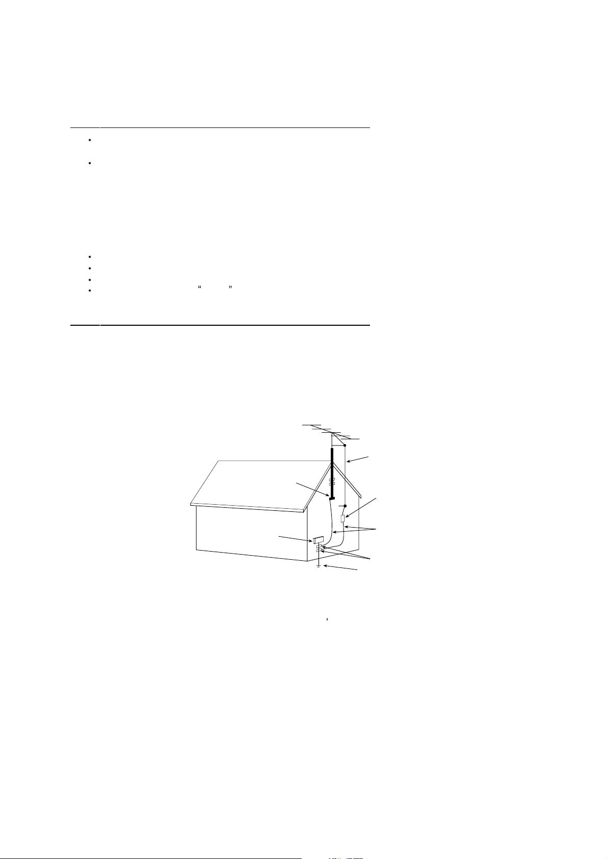
EXAMPLE OF ANTENNA GROUNDING AS PER NATIONAL ELECTRICAL CODE INSTR UCTIONS
EXAMPLE OF ANTENNA GROUNDING AS PER
NATIONAL ELECTRICAL CODE
ANTENNA
LEAD- IN WIRE
GROUND CLAMP
ELECTRIC SERVICE
EQUIPMENT
NEC-NATIONAL ELECTRICAL CODE
ANTENNA DISCHARGE
UNIT (NEC SECTION
810-20)
GROUNDING
CONDUCTORS
(NECSECTION 810-21)
GROUND CLAMPS
POWER SER VICE GROUNDING
ELECTRODE SYSTEM
(NEC ART 250. PART H)
15.2. Note to CATV system installer : (Only for the television set with CATV reception)
This reminder is provided to call the CATV system attention to Article 820-40 of the NEC that provides
installer s
guidelines for proper grounding and, in particular, specifies that the cable ground shall be connected to the grounding
system of the building, as close to the point of cable entry as practical.
16. An outside antenna system should not be located in the vicinity of overhead power lines or other electric lights or power
circuits, or where it can fall into such power lines or circuits. When installing an outside antenna system, extreme care
should be taken to keep from touching such power lines or circuits as contact with them might be fatal.
17. For added protection for this television set during a lightning storm, or when it is left unattended and unused for long
periods of time, unplug it from the wall outlet and disconnect the antenna. This will prevent damage due to lightning
and power-line surges.
4
Page 5

SCHNEIDER ELECTRONICS GMBH-GERMANY
OPERATION OF YOUR SET
18.
This television set should be operated only from the type of power source indicated on the marking label.If you are not
sure of the type of power supply at your home, consult your television dealer or local power company. For television
sets designed to operate from battery power, refer to the operating instructions.
19. If the television set does not operate normally by following the operating instructions, unplug this television set from the
wall outlet and refer servicing to qualifiedservice personnel. Adjustonly those controls that are covered in the operating
instructions as improper adjustment of other controls may result in damage and will often require extensive work by a
qualified technician to restore the television set to normal operation.
20. When going on a holiday : If your television set is to remain unused for a period of time, for instance, when you go on
a holiday, turn the television set and unplug the television set from the wall outlet.
off
IF THE SET DOES NOT OPERATE PROPERLY
21. If you are unable to restore normal operation by following the detailedprocedurein your operatinginstructions,
do not attempt any further adjustment. Unplug the set and call your dealer or service technician.
22. Whenever the television set is damaged or fails, or a distinct change in performance indicates a need for
service, unplug the set and have it checked by a professional service technician.
23. It is normal for some TV sets to make occasional snapping or popping sounds, particularly when being
turned on or off. If the snapping or popping is continuous or frequent, unplug the set and consult your
dealer or service technician.
FOR SERVICE AND MODIFICATION
24. Do not use attachments not recommendedby the television set manufacturer as they may cause hazards.
25. When replacement parts are required, be sure the service technician has used replacement parts specified
by the manufacturer that have the same characteristics as the original part. Unauthorized substitutions
may result in fire, electric shock, or other hazards.
26. Upon completion of any service or repairs to the television set, ask the ser vice technician to perform
routine safety checks to determine that the television is in safe operating condition.
5
Page 6

2. SPECIFICATION RELEASE
LCD 32V8SY
32' LCD Widescreen
HDTV Monitor
Features
Widescreen High Definition TV Monitor with 1366*768 High
Resolution Panel and Lightening Fast 16ms Response Time
Comprehensive Connectivity Package: DVI, PC D-Sub(VGA) In,
Component Video In, S-Video In, AV In (x3), Audio In for DVI
(1), Component Video (1) & PC D-Sub (3.5mm)
Exceptional Contrast and Brightness Performance
High Performance Video Processing with Advanced DeInterlacing
5-Line Digital Comb Filter(Y/C Separation with Adjustable
Vertical Peaking)
Benefits
Capable of viewing digital TV signals(480p,720p,1080i)in
720progressive lines,Lightening fast response time yields
crisp,clear,detailed images.
Connect a wide array of sources for greater utility, from VCR to
Progressive Scan DVD Player, Digital TV Tuner,Digital Cable
Box, Satellite, Game, or Personal Computer.
High contrast ratio and high brightness brings images to life with
bright,vivid color and outstanding detail.
Progressively converts incoming signals and up-converts to 768
progressive lines for improved resolution&clarity.Reverse 3:2 Pull
down keeps DVD images jitter-free.
Precision Y/C separation reduces interference generated by the
interlacing process of analog signals,resulting in clear,accurate
images with improved contrast.
SRS WOW
Standard Definition NTSC M & PAL M/N Integrated Tuner
Improves the audio experience by providing a 3-D audio image
that extend sound in both vertical and horizontal directions.
Built-in analog TV tuner receives standard over-the-air television
broadcasts and cable TV programming.
Page 7

Y
e
(
)
(
)
r
y
s
)
2. SPECIFICATION RELEASE
Technical Specifications
LCD32V8SY
PICTURE SIGNAL FORMAT CAPABILIT
Panel Size(inch) 32 Component Video Format Y,Pb/Cb,Pr/Cr: 480i,480p,720p,1080i@50Hz/60Hz
Category LCD TV DVI Video Format (720p,1080i)@50Hz/60Hz
Aspect Ratio 16:9 HDMI Video Format
Color Temperature Adjustable(Normal/Cool/Warm) PC Compatibility VGA: Up to 1280*1024 @75Hz
Backlight Adjustabl
Scaler Mode
Picture Effect 4 (Soft,Natural, Bright, Personal) S-Video Input 1
Film Mode(3:2 pull down) Yes Audio Input for S-Video Share with AV1
Picture Enhancement YPbPr Input
Comb Filter Digital 5-Line Audio Input for YPbPr
Gamma Correction Yes YCbCr Input
CCS Yes Audio Input for YCbCr
DCDI Yes VGA Input(RGB)
Blue Stretch
Black Stretch Yes DVI
Motion Compensation Yes Audio Input for DVI
DLTI Yes HDMI ˉ
DCTI Yes
Dynamic Skin Correction Yes Headphone Jack Output
DNR Yes RF Input(Antenna)
Panel Specification Scart
Panel Supplie
Viewing Technology MVA TV System
Display Resolution WXGA(1366*768) AV System
Brightness (cd/m2) 550 Channels
Contrast Ratio 800:1 Chassis Name
Response Time 16ms Market
Viewing Angle(H/V) 170°/170° Certification
Life Time 60,000hrs Power Supply
Color 16.7M Power Consumption-TV ON
SOUND Power Consumption-Standb
Speakers 2 - Side Integrated Default Color
Audio Power Output 2*8 W Front Cabinet
Sound Processing
DVSS (Dolby Virtual Surround)
AVC (Auto Volume Control) Yes Keyboard Position
BBE
SRS
Sound Control
Sound Features
Function Base Stand (mm)
V-Chip Yes - USA & Canada Net Weight (Kg)
CCD(Closed Caption) Yes Gross Weight (Kg)
Teletext
PIP/POP
Macro Vision Yes 40 feet
Calendar Yes 40 feet high
Clock/Timer
Lock Front Panel Block Operation Manual English
OSD Language English/Spanish/Portuguese/French Base Stand Included-Detachable
OSD Features Semi-transparent,Size & position adjustable Wall Mount
Card Reader
DVD Combo
USB Connection
Game
Screen Saver Yes
Demo Function
Yes TERMINALS
4:3, 14:9 Zoom, 16:9 Zoom, Cinerama, 16:9 Subtitles,
and 16:9 Widescreen.
ˉ
CMO Basic Info.
MTS stereo
ˉ
ˉ
SRS-WOW
5-Band Graphic Equalizer, 6 effects
(Stereo,Cinema,News,Surround,Custom,Concert)
Mono/Stereo
ˉ
ˉ
Timer(Sleep/Wake up/Turn off
ˉ
ˉ
ˉ
ˉ
ˉ
Audio/CVBS Inputs(Composite)
Audio Input for RGB
Audio/CVBS Outputs(Composite) 1 (R/L+CVBS) (RCA)
Rear Cabinet
Base Stand
Unpackaged Dimension for Main Body (L*H*D)
With Base Stand (mm)
Without Base Stand (mm)
Packaged Dimension (L*H*D)
Main Body (mm)
Speaker Box (mm)
Container Loading
20 feet
ACCESSORIES
Remote Control 06-015W33-A003X
Others
ˉ
3 (R/L) Audio,
3 Video:AV1,AV2,AV3
1
1 (R/L)
Share with "YPbPr"
Share with Audio Input for "YPbPr"
1 (D-Sub,15-Pin)
1
3.5mm
1(DVI-D, HDCP)
1 (R/L)
1
1 (F Type)
ˉ
NTSC M,PAL M/N
NTSC/PAL
181
PW118
EM2
CB
AC 100V-240V 50/60Hz
180W
Less than 3 W
Silver gray
Gray
Silver gray
Lower right on the front panel
980x638x300
1155x780x370
Integrated
Packaged with main body together
26 (main body with speaker,base stand)
31.5 (main body with speaker,base stand)
90
191
WMB300(optional)
Power cordˈBatteries
rear
Page 8

3. BOM LIST
PART NO. SEPC QTY LOCATION
V8-L32PS1-01D01 SOFTWARE CODE 1 U018
V8-L32PS1-01D02 SOFTWARE CODE 1 U001
V8-L32PS1-01M01 SOFTWARE CODE 1 U503
V8-L32PS1-07F01 ASS'Y - SOFTWARE 1 U020
09-0BAV70-ATX SMD DIODE BAV70 1 D514
09-55C5V1-DTX SMD.DIODE BZV55-C5V1 1 D506
09-FM5817-STX SMD.DIODE FM5817 4 D513;D510;D512;D511
09-LL4148-ATX SMD. SWITCHING DIODE LL4148 8 D505;D516;D507;D508;D509;D501;D504;D503
10-HS18VC-DBX DIODE 500MW 18HSC 1 D502
12-BT3904-0BX
12-BT3904-0BX
12-BT3906-0BX
12-C144ET-0BX SMD. TRANSISTOR PDTC144ET 2 Q509;Q510
12-D40N03-0BX MOSFSET NTD40 NO3RG 2 Q507;Q506
13-12F675-00B IC PIC12F675 1 U503
13-CS5211-G0B IC CS5211G 1 U502
13-L7809C-D2B IC L7809CD2T-TR (DDPAK) 1 U506
13-LD1117-50B 5.0V IC LD1117S50TR 1 U507
13-MSP345-0GB12 IC MSP34506-C12 1 U501
13-S35380-A0B IC S-35380A 1 U508
13-TA2024-00B IC TA2024 1 U505
13-TDA282-2DB IC E-TDA2822D013TR 1 U511
13-TV6415-DDB IC STV6415D 1 U504
19-BB0000-JTX SMD. RES 0 OHM 1/10W +/-5% 4 R503;L501;R650;R649
19-BB0000-JTX SMD. RES 0 OHM 1/10W +/-5% 8 R580;R622;R648;R618;R637;R594;R643;R579
19-BB0100-JTX RES. SMD 10 OHM 1/10W +/-5% 2 R575;R576
19-BB0101-JTX SMD. RES 100 OHM 1/10W +/-5% 7 R522;R599;R600;R641;R519;R508;R507
19-BB0102-JTX SMD. RES 1K OHM 1/10W +/-5% 2 R562;R559
19-BB0102-JTX SMD. RES 1K OHM 1/10W +/-5% 8 R558;R663;R664;R517;R516;R515;R509;R568
19-BB0102-JTX SMD. RES 1K OHM 1/10W +/-5% 8 R527;R644;R630;R631;R521;R518;R520;R645
19-BB0102-JTX SMD. RES 1K OHM 1/10W +/-5% 8 R554;R551;R550;R546;R539;R538;R535;R533
19-BB0103-JTX SMD. RES 10K OHM 1/10W +/-5% 8 R615;R598;R597;R574;R570;R544;R541;R532
19-BB0103-JTX SMD. RES 10K OHM 1/10W +/-5% 8 R510;R506;R569;R549;R632;R633;R616;R567
19-BB0103-JTX SMD. RES 10K OHM 1/10W +/-5% 1 R557
19-BB0123-FTX RES.SMD 12K 1/10W +/-1% 0805 1 R525
19-BB0151-JTX RES. SMD 150 OHM 1/10W +/-5% 2 R502;R504
19-BB0153-JTX SMD. RES 15K OHM 1/10W +/-5% 3 R584;R587;R590
19-BB0203-JTX SMD. RES 20K OHM 1/10W +/-5% 2 R571;R566
19-BB0221-JTX
19-BB0222-JTX SMD. RES 2.2K OHM 1/10W +/-5% 2 R573;R572
19-BB0223-JTX SMD. RES 22K OHM 1/10W +/-5% 8 R540;R545;R531;R548;R555;R528;R591;R529
19-BB0223-JTX SMD. RES 22K OHM 1/10W +/-5% 2 R588;R585
19-BB0302-FTX RES.SMD 3K0HM 1/10W +/-1% 1 R526
19-BB0470-JTX SMD. RES 47 OHM 1/10W +/-5% 1 R513
19-BB0473-JTX
19-BB0479-FTX SMD. RES 4.7 OHM 1/10W +/-1% 2 R636;R635
19-BB0513-JTX SMD. RES 51K OHM 1/10W +/-5% 1 R514
19-BB0680-JTX SMD. RES 68 OHM 1/10W +/-5% 0805 1 R512
19-BB0681-JTX SMD. RES 680 OHM 1/10W +/-5% 3 R586;R589;R592
19-BB0750-JTX SMD. RES 75 OHM 1/10W +/-5% 5 R583;R578;R577;R581;R582
19-BB0820-JTX RES. SMD 82 OHM 1/10W +/-5% 5 R534;R542;R543;R547;R556
19-BB0822-FTX RES.SMD 1/10W 8.2KOHM +/-1% 1 R565
19-CC0680-JTX RES. SMD 68 OHM 1/8W +/-5% 1 R617
SMD. TRANSISTOR MMBT3904LT1(NPN)
SMD. TRANSISTOR MMBT3904LT1(NPN)
SMD. TRANSISTOR MMBT3906LT1(PNP)
SMD. RES 220 OHM 1/10W +/-5% 0805
SMD. RES 47K OHM 1/10W +/-5% 0805
Q514;Q503;Q504;Q517;Q516;Q515;Q518;Q501
8
4 Q513;Q512;Q511;Q505
1 Q508
2 R501;R595
6 R536;R537;R552;R553;R560;R561
Page 9

25-BCB100-M1X CAP. ELEC 10 UF 16V +/-20% 3 C617;C606;C634
25-BCB100-M1X CAP. ELEC 10 UF 16V +/-20% 8 C527;C642;C530;C532;C533;C534;C531;C555
25-BCB100-M1X CAP. ELEC 10 UF 16V +/-20% 8 C577;C565;C558;C562;C506;C516;C529;C528
25-BCB101-M1X CAP. ELEC 100 UF 16V +/-20% 6 C632;C633;C547;C549;C636;C637
25-BCB101-M1X CAP. ELEC 100 UF 16V +/-20% 8 C560;C563;C566;C569;C571;C556;C603;C600
25-BCB220-M1X CAP. ELEC 22 UF 16V +/-20% 3 C605;C608;C602
25-BCB470-M1X CAP. ELEC 47 UF 16V +/-20% 6 C553;C598;C552;C522;C514;C505
25-BDA471-M1X CAP. ELEC 470 UF 25V +/-20% 6 C545;C546;C544;C537;C536;C535
25-BDB221-M1X CAP. ELEC 220UF 25V +/-20% 3 C580;C589;C583
25-BFB339-M1X CAP. ELEC 3.3 UF 50V +/-20% 1 C526
25-BFB479-M1X CAP. ELEC 4.7 UF 50V +/-20% 2 C519;C520
28-AB0102-KBX SMD. CAP 1000 PF 50V +/-10% B 2 C630;C631
28-BB0100-JCX SMD. CAP. 10PF 50V +/-5% 2 C609;C616
28-BB0102-KBX SMD CAP. 0.001UF 50V B 0805 4 C517;C644;C643;C518
28-BB0103-ZFX SMD CAP. 0.01 UF 50V F 0805 5 C559;C515;C513;C509;C504
28-BB0104-ZFX SMD CAP. 0.1 UF 50V +80/-20% 0805 8 C581;C579;C550;C551;C554;C604;C607;C610
28-BB0104-ZFX SMD CAP. 0.1 UF 50V +80/-20% 0805 8 C614;C618;C541;C635;C639;C638;C557;C561
28-BB0104-ZFX SMD CAP. 0.1 UF 50V +80/-20% 0805 8 C564;C662;C661;C582;C507;C525;C538;C539
28-BB0104-ZFX SMD CAP. 0.1 UF 50V +80/-20% 0805 8 C540;C542;C548;C568;C570;C572;C573;C574
28-BB0104-ZFX SMD CAP. 0.1 UF 50V +80/-20% 0805 7 C575;C601;C597;C595;C593;C588;C587
28-BB0105-ZFX SMD. CAP 1UF 50V +80%-20% 1 C594
28-BB0152-KBX SMD CAP. 0.0015UF 50V B 0805 1 C523
28-BB0224-ZFX
28-BB0224-ZFX
SMD. CAP 0.22UF 50V +80%/-20% 0805
SMD. CAP 0.22UF 50V +80%/-20% 0805
8 C503;C501;C500;C502;C584;C585;C590;C591
3 C596;C599;C625
28-BB0339-CCX SMD. CAP 3.3PF 50V +/-0.25PF 2 C511;C512
28-BB0471-JCX SMD. CAP 470PF 50V +/-5% 1 C521
28-BB0474-ZFX SMD. CAP 0.47UF 50V +80% -20% 2 C586;C592
28-BB0560-JCX SMD. CAP 56PF 50V +/-5% 2 C508;C510
28-BB0820-JCX SMD. CAP. 82PF 50V +/-5% 4 C615;C613;C612;C611
28-BC0225-ZFX SMD. CAP 2.2UF 16VDC +/-20% 2 C640;C641
28-BD0683-KBX CAP.SMD 683 25V +/-10 0805 X7R 2 C578;C576
33-ELN201-NTX CHIP BEAD 200 OHM +/-25% 4 L530;L529;L528;L527
33-ELN201-NTX CHIP BEAD 200 OHM +/-25% 8 L523;L524;L525;L526;L520;L521;L522;L531
33-GLL100-KTX SMD. COIL 10 UH +/-10% CMI3216 1 L502
33-GLL100-KTX SMD. COIL 10 UH +/-10% CMI3216 8 L503;L506;L507;L508;L513;L514;L515;L519
33-GLL220-KTX SMD.COLL 22UH +/-10% 1 L504
33-PLL100-MTX SMD COIL SPI127QR-100 1 L505
34-R100K2-10X COIL CHOKE SG9006 10UH +/-20% 4 L510;L509;L511;L512
36-371620-00X NETWORK FILTER NF0801 1 U509
40-D32V6N-MAF2X P.C.B MAIN BD 1
43-SFSS11-2DM RELAY SF-SS-112DM 1 RELA1
45-OSC18M-4Y0 CRYSTAL 18.432M 1 X501
45-OSC32K-7Y0 CRYSTAL 32.768KHZ 1 X502
46-33079W-04X PIN BASE *4 TJC3-4A 1 J507
46-33079W-09X PIN BASE *9 TJC3-9A 1 J504
46-33333W-03X PIN BASE 1 J501
46-35199W-05X CONN.PH-5A 5PIN PITCH=2.0MM 1 J502
46-35199W-06X .PH-6A 6PIN PITCH-2.0MM 1 J508
46-35199W-07X CONN.PH-7A PITCH=2.0MM 7PIN 1 J503
46-39686H-04X 4P UL2468#22 1000/800MM 1 FOR J507
46-39690W-64X CONNECTOR 64PIN 32X2 2.0X2.0 1 J505
46-CC005T-09Q HS 9P UL4007#24 50MM 1 FOR J504
46-FF010F-05001 HS 5P UL1185#26 100MM 1 FOR J502
46-FF042T-07X HS 7PIN Y0509074.3 1 FOR J503
47-RCA009-XX4 RCA SOCKET AV-3.2-3W-052 3 P501;P504;P506
47-SVI008-XX1 SOCKET DSW-506WT-L 1 P503
49-382630-BAT BATT. CR2025 1 BT1
Page 10

67-387200-3A0 HEAT SINK 1 FOR U505
71-268390-0A0AF LABEL (QC) GREEN 1
71-BAR005-XX0 LABEL BAR CODE 1
55-718510-0HA5C BASE 1
57-702250-0HD HOST FOOT PAD 6
63-B40100-AB4 S/T SCREW B 4 X 10 AB 12 base armor plate to base cover
64-B40100-102 M/C SCREW B 4 X 10 8 base armor plate to base support
64-F40200-102 MACHINE SCREW F4X20 4 base support to support linker
67-C71746-0A05C BASE SUPPORT 2
67-C71756-0A05C BASE SUPPORT COVER 2
67-M71720-0E0 SOLEPLATE 1
09-0BAV70-ATX SMD DIODE BAV70 2 D012;D004
09-0BAV99-ATX HIGH SPEED DOUBLE DIODE BAV99 4 D009;D003;D007;D006
09-0BAV99-ATX HIGH SPEED DOUBLE DIODE BAV99 8 D010;D008;D013;D011;D002;D014;D015;D016
09-0BAV99-ATX HIGH SPEED DOUBLE DIODE BAV99 8 D019;D018;D017;D020;D021;D022;D023;D024
12-BT3906-0BX
SMD. TRANSISTOR MMBT3906LT1(PNP)
3 Q008;Q005;Q006
12-C144ET-0BX SMD. TRANSISTOR PDTC144ET 3 Q003;Q007;Q002
13-0024LC-21B IC 24LC21-SOIC8(WRITE) 2 U001;U018
13-128168-A6B DDR SDRAM M13S128168A 2 U013;U012
13-63LVDM-83B IC THC63LVDM83R 1 U003
13-74AHCT-08B AND GATE 74AHCT08PW 1 U019
13-AIC108-4PB IC AIC1084PM 1 U015
13-AL008D-70BT2 FLASH 8M S29AL008D70TFI02 1 U020
13-EF4052-BTB IC HEF4052BT(D) 1 U005
13-IC1084-25B IC 2.5V 5A AIC1084-25CM 1 U016
13-IC1084-CMB IC AIC1084-33CM 3.3V (TO-263) 1 U014
13-IRF731-40B IC IRF7314 1 U004
13-LD1117-18B 1.8V REGULATOR IC LD1117S18TR 1 U006
13-LD1117-33B IC LD1117 3.3V 1 U007
13-M24C32-MNB IC SM M24C32-WMN6P(ST00) R 1 U021
13-PT7809-STB IC PT7M7809ST 1 U09
13-PW1181-0LB
DEINTERLACER AND SCALER PW118-10
1 U002
13-PW3300-10B IC PW3300-10 1 U008
13-SRV054-CTB IC SRV05-4 TCT 2 D001;D005
19-AA0152-JTX 1206 SMD.RES.1.5K OHM 1/16W 5% 2 R069;R071
19-AA0221-JTX RES. SMD 220 OHM 1/16W +/-5% 1 R216
19-AB0000-JTX RES SMD 0 OHM 1/10W +/-5% 0603 5 R091;R127;R128;R129;R088
19-AB0000-JTX RES SMD 0 OHM 1/10W +/-5% 0603 8 R067;R229;R227;R038;R209;R198;R196;R193
19-AB0000-JTX RES SMD 0 OHM 1/10W +/-5% 0603 8 R068;R070;R086;R107;R114;R125;R149;R066
19-AB0000-JTX RES SMD 0 OHM 1/10W +/-5% 0603 8 R228;R030;R028;R213;R148;R024;R063;R065
19-AB0100-JTX RES SMD 10 OHM 1/10W +/-5% 1 R221
19-AB0101-JTX RES SMD 100 OHM 1/10W 0603 1 R174
19-AB0102-JTX RES SMD 1K OHM 1/10W 0603 7 R215;R160;R102;R103;R175;R176;R092
19-AB0103-JTX RES SMD 10K OHM 1/10W 0603 8 R077;R076;R034;R027;R078;R084;R089;R130
19-AB0103-JTX RES SMD 10K OHM 1/10W 0603 6 R167;R132;R152;R153;R165;R166
19-AB0105-JTX RES SMD 1M OHM 1/10W 0603 2 R073;R218
19-AB0155-JTX
19-AB0201-JTX
19-AB0202-JTX
SMD. RES 1.5M OHM 1/10W +/-5% 0603
SMD. RES 200 OHM 1/10W +/-5% 0603
SMD. RES 2K OHM 1/10W +/-5% 0603
1 R116
1 R018
2 R163;R164
19-AB0220-JTX SMD RES 22 OHM 1/10W 0603 8 R101;R100;R015;R013;R012;R010;R009;R004
19-AB0220-JTX SMD RES 22 OHM 1/10W 0603 2 R003;R001
19-AB0222-JTX RES SMD 2.2K OHM 1/10W 0603 2 R147;R146
19-AB0223-JTX
19-AB0223-JTX
19-AB0223-JTX
19-AB0243-JTX
19-AB0271-JTX
SMD. RES 22K OHM 1/10W +/-5% 0603
SMD. RES 22K OHM 1/10W +/-5% 0603
SMD. RES 22K OHM 1/10W +/-5% 0603
SMD. RES 24K OHM 1/10W +/-5% 0603
SMD. RES 270 OHM 1/10W +/-5% 0603
5 R059;R058;R057;R056;R055
8 R060;R061;R046;R222;R223;R225;R226;R031
8 R047;R048;R049;R050;R051;R052;R053;R054
1 R137
1 R217
Page 11

19-AB0332-JTX SMD RES 3.3K OHM 1/10W 0603 6 R140;R171;R168;R150;R131;R122
19-AB0391-FTX
SMD. RES 390 OHM 1/10W +/-1% 0603
1 R112
19-AB0392-JTX SMD. RES 3.9K OHM 1/10W +/-5% 4 R135;R136;R220;R219
19-AB0470-JTX RES SMD 47 OHM 1/10W +/-5%0603 8 R138;R139;R117;R099;R087;R085;R083;R081
19-AB0470-JTX RES SMD 47 OHM 1/10W +/-5%0603 8 R075;R134;R123;R124;R121;R120;R119;R118
19-AB0470-JTX RES SMD 47 OHM 1/10W +/-5%0603 4 R151;R154;R126;R133
19-AB0472-JTX RES SMD 4.7K OHM 1/10W 0603 8 R029;R033;R093;R145;R115;R144;R007;R006
19-AB0472-JTX RES SMD 4.7K OHM 1/10W 0603 2 R008;R224
19-AB0473-JTX SMD. RES 47K OHM 1/10W 0603 7 R041;R040;R042;R043;R044;R045;R026
19-AB0682-JTX RES SMD 6.8K OHM 1/10W 0603 1 R025
19-AB0750-JTX SMD. RES 75 OHM 1/10W 0603 8 R002;R005;R011;R173;R187;C195;R190;R170
19-AB0750-JTX SMD. RES 75 OHM 1/10W 0603 5 R014;R155;R156;R157;R169
19-AB0751-FTX SMD. RES 750 OHM 1/10W +/-1% 1 R111
19-CD0000-JTX RES.SMD 0 OHM 1206 4 L027;L029;L025;R021
23-A08220-JBX NETWORK RES. 22 OHM +/-5% 4 RP025;RP026;RP027;RP028
23-A08220-JBX NETWORK RES. 22 OHM +/-5% 6 RP032;RP031;RP030;RP022;RP023;RP024
23-A08220-JBX NETWORK RES. 22 OHM +/-5% 6 RP021;RP018;RP017;RP019;RP020;RP029
23-A08470-JBX
23-A08470-JBX
23-A08470-JBX
23-A08470-JBX
CHIP ARRAY RES. 47 OHM +/-5% 0603*4
CHIP ARRAY RES. 47 OHM +/-5% 0603*4
CHIP ARRAY RES. 47 OHM +/-5% 0603*4
CHIP ARRAY RES. 47 OHM +/-5% 0603*4
6 RP039;RP038;RP037;RP036;RP035;RP003
6 RP002;RP040;RP041;RP042;RP043;RP044
6 RP045;RP046;RP047;RP009;RP007;RP001
6 RP004;RP034;RP033;RP011;RP006;RP005
28-AB0102-JCX SMD. CAP 1000PF 50V +/-5% 0603 5 C176;C184;C191;C164;C215
28-AB0103-ZFX CAP.SMD 10NF 50V +80-20% 0603 2 C018;C019
28-AB0104-ZFX CAP. SMD 0.1UF 50V +80%~-20% F 1 C216
28-AB0120-JCX SMD. CAP 12 PF 50VDC 0603 +/-5% 3 C180;C179;C178
28-AB0180-JCX SMD. CAP 18 PF 50V +/-5% 0603 8 C202;C085;C157;C158;C200;C201;C084;C083
28-AB0224-ZFX CAP.SMD 0.22UF 50V +80-20%0603 6 C196;C192;C187;C177;C174;C173
28-AB0392-KBX
SMD. CAP 3900 PF 50VDC +/-10% 0603
1 C159
28-AB0393-ZFX SMD. CAP 0.039 UF 50V +80%-20% 1 C160
28-AB0471-JCX CAP.SMD 470PF 50V +/-5% 0603 1 C214
28-AC0105-ZFX SMD. CAP 1 UF 16VDC +80%/-20% 2 C213;C217
28-AD0104-ZFX SMD CAP 0.1UF 25V +80-20% 0603 8 C095;C124;C123;C122;C121;C120;C119;C118
28-AD0104-ZFX SMD CAP 0.1UF 25V +80-20% 0603 8 C063;C064;C065;C066;C067;C032;C072;C071
28-AD0104-ZFX SMD CAP 0.1UF 25V +80-20% 0603 8 C099;C098;C097;C046;C048;C050;C096;C094
28-AD0104-ZFX SMD CAP 0.1UF 25V +80-20% 0603 8 C114;C109;C105;C104;C103;C102;C101;C100
28-AD0104-ZFX SMD CAP 0.1UF 25V +80-20% 0603 8 C022;C125;C008;C007;C006;C005;C002;C001
28-AD0104-ZFX SMD CAP 0.1UF 25V +80-20% 0603 8 C069;C070;C051;C013;C014;C015;C016;C021
28-AD0104-ZFX SMD CAP 0.1UF 25V +80-20% 0603 8 C026;C027;C028;C029;C030;C060;C061;C062
28-AD0104-ZFX SMD CAP 0.1UF 25V +80-20% 0603 8 C031;C068;C055;C056;C057;C058;C059;C025
28-AD0104-ZFX SMD CAP 0.1UF 25V +80-20% 0603 8 C140;C139;C138;C137;C136;C134;C133;C023
28-AD0104-ZFX SMD CAP 0.1UF 25V +80-20% 0603 8 C182;C181;C024;C141;C144;C145;C146;C147
28-AD0104-ZFX SMD CAP 0.1UF 25V +80-20% 0603 8 C163;C165;C171;C172;C175;C186;C185;C183
28-AD0104-ZFX SMD CAP 0.1UF 25V +80-20% 0603 8 C167;C169;C154;C155;C053;C082;C077;C156
28-AD0104-ZFX SMD CAP 0.1UF 25V +80-20% 0603 8 C078;C151;C150;C149;C052;C168;C166;C170
28-AD0104-ZFX SMD CAP 0.1UF 25V +80-20% 0603 8 C090;C089;C088;C087;C086;C081;C080;C079
28-AD0104-ZFX SMD CAP 0.1UF 25V +80-20% 0603 8 C131;C132;C054;C073;C076;C093;C092;C091
28-AD0104-ZFX SMD CAP 0.1UF 25V +80-20% 0603 8 C148;C074;C075;C126;C127;C128;C129;C130
28-RA0107-MAX SMD. CAP 100 UF 10V +/-20% 6 C152;C135;C116;C115;C111;C110
28-RC0106-MAX SMD. CAP 10 UF 16V +/-20% 8 C045;C044;C043;C042;C017;C020;C035;C036
28-RC0106-MAX SMD. CAP 10 UF 16V +/-20% 5 C037;C038;C041;C040;C039
28-RC0226-MAX SMD. CAP 22 UF 16V +/-20% 2 C033;C034
28-RC0476-MAH SMD. CAP 47 UF 16V +/-20% 2 C047;C049
28-RD0477-MAX ALUMINIUM CAP. 470 UF 25V +/-20% 2 C108;C107
33-ELN221-NTX CHIP BEAD 220 OHM +/-25% 1 L004
33-ELN301-NTX BEAD CHIP HB-1T2012-301 2012 2 R201;R202
33-GLN121-NTX CHIP BEAD 120 OHM +/-25% 5 L013;L009;L003;L002;L024
33-GLN121-NTX CHIP BEAD 120 OHM +/-25% 8 L005;L006;L007;L008;L015;L017;F001;L016
Page 12

33-GLN121-NTX CHIP BEAD 120 OHM +/-25% 7 L020A;L014A;L013A;L001A;L017A;L019;L026
33-GLN121-NTX CHIP BEAD 120 OHM +/-25% 7 L028;L001;L020;L018;L014;L016A;L018A
33-KLN121-NTX CHIP BEAD 120 OHM +/-25% 6 L023;L022;L021;L012;L011;L010
33-KLN181-NTX SMD BEAD CHIPHB 180 OHM 2 R141;R142
33-KLN601-NTX CHIP BEAD 600 OHM +/-25% 3 L032;L031;L030
40-D32V6N-DIC4X P.C.B.DIGIBOARD 1
45-OSC14M-3Y2 CRYSTAL 14.31818MHZ 1 Y001
45-OSC27M-0Y3 CRYSTAL 27MHZ 1 Y002
46-33079W-09X PIN BASE *9 TJC3-9A 1 J008
46-35199W-04X CONN.PH-4A 4PIN PITCH=2.0MM 2 J011;J009
46-35199W-07X CONN.PH-7A PITCH=2.0MM 7PIN 1 P003
46-38612W-30X PIN BASE DF14-30P(WF) 1.25PITCH 1 P002
46-39689W-64X CONNECTOR 1 J005
46-FF025F-04001 HS 4P UL1185#26 250MM 1 FOR J009
47-DVI001-XX0 DVI SOCKET DVFR283-PC0-NP 1 P001
47-EAR005-XX0 EARPHONE SOCKET CK3-3.5-3WK-E 1 J002
47-RCA009-XX4 RCA SOCKET AV-3.2-3W-052 1 J006
47-RCA123-XX0 RCA SOCKET AV-3.2-2W-G6 2 J003;J004
47-RCA125-XX1 RCA SOCKET AV-3.2-3W-051 1 J007
47-VGA004-XX0 VGA SOCKET D-SUB-15S(BLACK) 1 P004
67-387190-0A0 HEAT SINK 1 FOR U002
67-387190-1A0 HEAT SINK 2 FOR U013;FOR U012
67-H42094-0A0 HEAT SINK 1 FOR U008
71-268390-0A0AF LABEL (QC) GREEN 1
71-BAR005-XX0 LABEL BAR CODE 1
26-EBP104-ZFX CAP. CER 0.1UF 50V +80%/-20% 1 C21
40-D32V6N-EAB1X P.C.B EA BD 1
46-35199W-06X .PH-6A 6PIN PITCH-2.0MM 1 J1
47-EAR002-XX0 EARPHONE SOCKET CK3-3.5-9WK-B 1 J2
02-IRR001-XX5 IR RECEIVER MODULE AT156A 1 IR1
12-BC857C-0BX SMD.TRANSISTOR BC857C 1 Q2
14-LED05R-XX1 LED RED FB205 1 LED1
19-BB0000-JTX SMD. RES 0 OHM 1/10W +/-5% 1 R3
19-BB0102-JTX SMD. RES 1K OHM 1/10W +/-5% 2 R10;R11
19-BB0152-JTX SMD. RES 1.5K OHM 1/10W +/-5% 2 R6;R9
19-BB0221-JTX
SMD. RES 220 OHM 1/10W +/-5% 0805
2 R1;R2
19-BB0222-JTX SMD. RES 2.2K OHM 1/10W +/-5% 2 R5;R8
19-BB0512-JTX SMD. RES 5.1K OHM 1/10W +/-5% 2 R4;R7
28-BB0101-JCX SMD CAP. 100 PF 50V C 0805 4 C2;C1;C8;C7
28-BB0104-JCX SMD.CAP 0.1UF 50V +/-5% 2 C4;C6
28-BB0105-ZFX SMD. CAP 1UF 50V +80%-20% 1 C3
28-XC0106-MTX TANTALUM CAP.10 UF 16V +/-20% 1 C5
33-GLN222-NTX
CHIP BEAD MGGB3216 M222HT 1206 2.2K
1L1
40-LD32V8-IRB1X P.C.B RECEIVE BD 1
46-35135W-07X PIN BASE PH-07AW 1 P6
46-FF055F-07001 HS 7P UL1007#24 550MM 1 FROM P6 TO AN J503
48-TAC001-XX0 TACT SWITCH 6 SW1;SW5;SW4;SW6;SW2;SW3
46-39674F-30X01
46-39687H-32X 32P UL1617#18 640/600/400MM 1
46-AK076T-02F01 HS 2PIN Y0509074.1 1
HS 30#/WL1253H-30 TV1217HN0-30 220MM
1
power PCB to digital PCB/to analog PCB/inverter line
VZLWFK3&%WRSRZHU3&%OLQH
47-PWS014-XX4 FILTER SOCKET 03GEEW3E8-1(04) 1
4A-LCD32T-CM0 LCD V320B1-L01 1
54-715620-0U0 SPONGE 960X8X4 MM 0.5
54-805890-0U0 SPONGE 2 for front cabinet
54-805890-1U0 SPONGE 2 for front cabinet
55-718490-1HN9D FRONT CABINET 1
56-718160-0HA1A REAR AV BRACKET 1
Page 13

56-718290-0HA5C PUSH BUTTON 1
1
56-718330-0HC5Z LENS 1
56-718570-0HA5C POWER KNOB 1
63-B30100-AB4 S/T SCREW B 3 X 10 AB 12 FOR RCA
63-B30100-AB4 S/T SCREW B 3 X 10 AB 3 MTG FRONT CTL BD & FRONT CABINET
63-B40150-AB3 S/T SCREW B 4 X 15 AB (BLACK) 12 MTG BRACKET& FRONT CABINET
63-S30100-AB4 S/T SCREW S 3 X 10 AB 2 MTG POWER PCB& FRONT CABINET
63-S30100-AB4 S/T SCREW S 3 X 10 AB 4 MTG SPK(RIGHT)& FRONT CABINET
63-S30100-AB4 S/T SCREW S 3 X 10 AB 4 MTG SPK(LEFT)& FRONT CABINET
63-W30080-AB4 S/T SCREW W 3 X 8 AB 1 MTG LENS & FRONT CABINET
64-B30060-104 M/C SCREW B 3 X 6 2 power switch stator & hard switch
64-B30060-104 M/C SCREW B 3 X 6 2 for back AV bracket & small iron breacket(right)
64-B30080-104 M/C SCREW B 3 X 8 5 FOR SHIDLDING COVER
64-B30080-104 M/C SCREW B 3 X 8 4 MTG TUNER BOARD& BIG BRACKET
64-B30080-104 M/C SCREW B 3 X 8 4 MTG SIGHAL BOARD& BIG BRACKET
64-B30080-104 M/C SCREW B 3 X 8 1
MTG POWER BRACKET& CROSSING BRIDGE
64-B30080-104 M/C SCREW B 3 X 8 4 MTG AV BOARD& BIG BRACKET
64-B30100-303 M/C SCREW TRIANGLE B 3 X 10 4 FOR POWER SUPPLY
64-B40080-104 M/C SCREW B 4 X 8 1 MTG RIGHT SMALL BRACKET& CROSSING
64-B40080-104 M/C SCREW B 4 X 8 2 MTG BIG BRACKET& CROSSING BRIDGE
64-B40080-104 M/C SCREW B 4 X 8 2
MTG LEFT SMALL BRACKET& ALUMINUM BAR
64-B40080-104 M/C SCREW B 4 X 8 4 MTG BIG BRACKET& ALUMINUM BAR
64-B40080-104 M/C SCREW B 4 X 8 2
64-B40080-104 M/C SCREW B 4 X 8 1
MTG RIGHT SMALL BRACKET& ALUMINUM BAR
MTG LEFT SMALL BRACKET& CROSSING BRIDGE
64-B40080-104 M/C SCREW B 4 X 8 8 MTG CROSSING BRIDGE& ALUMINUM BAR
64-B40080-104 M/C SCREW B 4 X 8 10 MTG BRACKET& LCD PANEL
64-B40120-103 M/C SCREW M 4 X 12 4 MTG BRACKET& LCD PANEL
64-F30080-104 M/C SCREW F 3X8 2 MTG AV BRACKET& BIG BRACKET
64-F30080-104 M/C SCREW F 3X8 2 MTG TUNER BOARD& BIG BRACKET
64-F30080-104 M/C SCREW F 3X8 2 MTG POWER BRACKET& POWER SOCKET
64-F40080-104 M/C SCREW M 4 X 8 8
MTG SUPPORT CONNECTOR & CROSSING BRIDGE
64-Z30060-1040A MACHINE SCREW 1 for grounding screw
66-702620-0E2 SCREW POST 4 FOR DVI;FOR VGA
67-C71722-0A0 BRACKET CONNECTOR 2
67-H71718-0A0 ALUMINUM BAR 2
67-L71622-2N09A LOGO 1
67-M71719-0E0 BRACKET 1
67-M71729-0E01A TUNER BRACKET 1
67-M71730-1E0 BRACKET 1
67-M71867-1E0 BRACKET 1
67-M71868-3E0 BOARD 1
67-M71869-1E0 BRACKET(RIGHT) 1
67-M71870-0E0 TRANSOM 2
67-M80454-0E0 POWER SWICTH NIP 1
67-S71731-4E0 SCREEN COVER 1
67-X22898-0E0 SPRING - KNOB 1
81-LC32A7-PW1 32"SMPS JSK3220-007A 1
57-10654X-00F TWIST TIE NY66 6
57-29635X-00F CABLE TIES (4.8MMX160MM) 5
57-KYWCC1-0UG0
WIRE MOUNT 6
67-V330Y1-0M4 METAL TIE 3
06-011W33-A202X
REMOTE CONTROLLER RC1113326/00
1
49-267710-BAT BATT. R6P AA SUM3 5# 2
51-PC0220-0WU08 POWER CORD 1
54-LCPVC6-000 INLAY 1
70-271510-00A SERVICE CARD 1
71-270870-0A9 LABEL 2
Page 14

72-32V8SY-S139A OPERATION MANUAL 1
74-026035-6WE9B POLYBAG 1
74-110085-50G9B PALSTIC BAG 1
75-813420-CC0 POLYFOAM"UL" 1
75-813430-CC0 POLYFOAM"UR" 1
75-813440-CC0 POLYFOAM"LL" 1
75-813450-CC0 POLYFOAM"LR" 1
75-813460-CC0 POLYFOAM"LL" 1
75-813470-CC0 POLYFOAM"LR" 1
76-813480-0AT9C CARTON BOX 1
55-718080-0HA1A FRONTPANEL 2
55-718500-0HN1C REAR CABINET 1
58-32V8MP-0UI9A INLAY MODEL NO. 1
58-718040-0UI1F INLAY 1
58-718040-0UI1G INLAY 1
63-B40150-AB3 S/T SCREW B 4 X 15 AB (BLACK) 14
25-DFB229-M1X CAP. ELEC 2.2 UF 50V +/-20% BP 1
42-07808G-XX2 SPEAKER YDF78-8R2 8 OHM 10W 1
"-"to mediant speaker PIN3,"+"to mediant speaker"-"
42-G3508F-XX0 SPEAKER 8 OHM 8W 1
54-700770-000
SPEAKER AIRPROOF STRIP 6MMX1MMX2000MM
0.5
59-718520-000 SOUND BOX BAR 4 althorn to front cover
62-717900-0HA5K FRONT COVER (LEFT) 1
62-717910-0HA5K REAR CABINET(RIGHT) 1
62-717950-0HA5K ECHO CANISTER 1
62-717960-0HA5K ECHO CANISTER 1
63-B30100-AB4 S/T SCREW B 3 X 10 AB 8 aftersound canister to front cover
63-B30100-AB4 S/T SCREW B 3 X 10 AB 6
sackbut to fornt cover;sound box front cover to rear cover
63-W30100-AB4 S/T SCREW W 3 X 10 AB 2
25-DFB229-M1X CAP. ELEC 2.2 UF 50V +/-20% BP 1
42-G3508F-XX0 SPEAKER 8 OHM 8W 1
54-700770-000
SPEAKER AIRPROOF STRIP 6MMX1MMX2000MM
0.5
59-718520-000 SOUND BOX BAR 4 sound box front cover to sound box rear cover
63-W30100-AB4 S/T SCREW W 3 X 10 AB 2
40-LD32V8-SWB1X P.C.B. SWITCH BD 1
46-35184W-02X PIN BASE *2 TJC1-2A 2 P2;P1
48-POW007-XX1 POWER SWITCH 1 SW001
54-806060-0U0
⬉⑤ᓔ݇㒱㓬⠛
1 FOR PCB
07-457FF5-TB1G TUNER TMQH6-019A 1 TUN1
09-LL4148-ATX SMD. SWITCHING DIODE LL4148 1 D701
11-SC1815-YBX TRANSISTOR 2SC1815-Y (NPN) 1 Q36
12-BT3904-0BX
SMD. TRANSISTOR MMBT3904LT1(NPN)
3 Q701;Q702;Q703
13-LD1117-50B 5.0V IC LD1117S50TR 1 U702
13-MC3406-3AB IC MC34063AD (SO-8) 1 U8
19-BB0000-JTX SMD. RES 0 OHM 1/10W +/-5% 4 R720;R726;R711;R712
19-BB0101-JTX SMD. RES 100 OHM 1/10W +/-5% 1 R718
19-BB0103-JTX SMD. RES 10K OHM 1/10W +/-5% 1 R707
19-BB0104-JTX
SMD. RES 100K OHM 1/10W +/-5% 0805
2 R710;R723
19-BB0109-JTX SMD. RES 1 OHM 1/10W +/-5% 0805 2 R709;R714
19-BB0122-FTX
SMD. RES 1.2K OHM 1/10W +/-1% 0805
1 R715
19-BB0181-JTX SMD. RES 180 OHM 1/10W +/-5% 1 R704
19-BB0221-JTX
SMD. RES 220 OHM 1/10W +/-5% 0805
2 R705;R713
19-BB0223-JTX SMD. RES 22K OHM 1/10W +/-5% 3 R706;R702;R701
19-BB0303-FTX RES.SMD 30K 0HM 1/10W +/-1% 1 R716
19-BB0331-JTX
SMD. RES 330 OHM 1/10W +/-5% 0805
1 R708
19-BB0471-JTX SMD. RES 470 OHM 1/10W +/-5% 1 R703
25-BCB101-M1X CAP. ELEC 100 UF 16V +/-20% 4 C702;C710;C716;C718
25-BDB100-M1X CAP. ELEC 10 UF 25V +/-20% 1 C703
Page 15

25-BFB220-M1X CAP. ELEC 22 UF 50V +/-20% 1 C713
25-BFB470-M1X CAP. ELEC 47 UF 50V +/-20% 1 C714
28-BB0103-ZFX SMD CAP. 0.01 UF 50V F 0805 1 C707
28-BB0104-ZFX SMD CAP. 0.1 UF 50V +80/-20% 0805 7 C701;C709;C711;C712;C715;C717;C719
28-BB0334-ZFX SMD. CAP 0.33UF 50V +80%/-20% 1 C724
28-BB0470-JCX SMD CAP. 47 PF 50V C 0805 3 C722;C705;C706
28-DC0107-MTX
TANTALUM CAP. 100 UF 16VDC +/-20%
1 C708
33-ELM100-KTX SMD. COIL 10UH +/-10% 0805 1 L702
33-GLL100-KTX SMD. COIL 10 UH +/-10% CMI3216 1 L705
34-R101K2-1BX COIL CHOKE 100 UH +/-10% 2 L703;L704
34-R120J2-0EX COIL PL - 12 UH +/-5% 1 L701
34-R221J2-0EX COIL PL - 220 UH +/-5% 1 LN9
40-D32V6N-TUC2X P.C.B TUNER BD 1
46-35199W-04X CONN.PH-4A 4PIN PITCH=2.0MM 1 J702
46-35199W-05X CONN.PH-5A 5PIN PITCH=2.0MM 1 J701
71-268390-0A0AF LABEL (QC) GREEN 1
71-270870-0A9 LABEL 2
Page 16

4. ALLIGNMENT PROCEDURE
1 Scopeġ
AFC031A chassis is developed for America market which supports 1 analog RF input,1 VGA input,
1 DVI input,1 compenent input,1 Video input,1 S-Video input.
2 Alignment content and methodġ
2.1 How to enter the Factory Menu
2.1.1 press “vol-” button on the remote control to decrease volume to zero
2.1.2 press “mute” buttonēmake mute icon displays on the right screen
2.1.3 input the password “9735” in 5S,then factory appears on the left up screen
2.2 How to enter Service Menu:
2.2.1 press “vol-” button on the remote to decrease volume to zero
2.2.2 press “mute” buttonēmake mute icon displays on the right screen
2.2.3 input the password “3175” in 5S,then Service Menu appears on the center screen
3 check picture geometry in VGA source
3.1 preparation and connection
3.1.1 connnect VGA cable from Chroma2327 port to set VGA input port
3.1.2 choose the “Crosshatch” pattern and the specified timing
Remark:following timing is specified
640*480@60Hz,640*480@75Hz,800*600@60Hz,800*600@72Hz,800*600@75Hz,1024*768
@60Hz,1024*768@75Hz
3.1.3 enter the “Geometry” sub-menu,make “Auto Ajust”,the picture should display in the center of the
screen,should not have distortioncnoise,etc.
4 manual white balance alignment
4.4 VGA source
4.4.1 press “input” button to choose the VGA source
4.4.2 connect VGA cable from Chroma2327
4.4.3 in “picture” sub-menu,set “warmth” item “normal”,set “Picture Preset” item “Natural”
4.4.4 enter factory menu
4.4.5 enter “Balance” sub-menu
4.4.6 input 1024*768@75 format,11Grays pattern
4.4.7 in “Balance” sub-menu,choose “VGAcalbr”,press “ok” button to selection RGB ADC calibration
4.4.8 input white pattern
4.4.9 select R\G\B Offset & Gain calibration.Target is:(x,y)=(299,315)
4.5 TV source
4.5.1 connect video signal to the video P501 connector and Fluke5418 video connector
4.5.2 choose VID1 source
4.5.3 input white pattern
4.5.4 select R\G\B Offset & Gain calibration.Target is:(x,y)=(285,294Đ
4.6 YPbPr source
4.6.1 connect YPbPr signal to J007 connector
4.6.2 choose CMPT source
4.6.3 input the SMPTE Color Bar pattern,720p60Hz format,like the attached figure1
Page 17

4.6.4 select YUVcalbr and press ok on RC
4.6.5 input the special pattern(attached figure2),select Y/G Offset in ADCBal sub-menu calibration to j-
ust see 6 level grays
6grays
Figure2 grays pattern
4.6.6 select Y/G Gain calibration to just see 6grays,figure3.
Page 18

Figure3 grays pattern 6grays
4.6.7 input Chroma2327 30IRE gray pattern,format 720p60Hz;
4.6.8 select R/G/B Offset calibration,target is (x,y)=(285,294)
4.6.9 input 100 IRE gray pattern,selection R/G/B Gain calibration,target is (x,y,Y)=(285,294,260~280
nit)
5 in case reloading the system software,it is necessary to enter factory menu to Reset data
Page 19

GSDA
GSCL
RX2m
R002
RX1m
RX2p
75
R005
75
RX0m
RX1p
R011
75
RX0p
RXCp
R014
75
RXCm
R001 26.7
0.1uF
C002
AV33
AV33
0.1uF
C001
4
5
AV33
6
D001 srv05-4
V33SW
L001
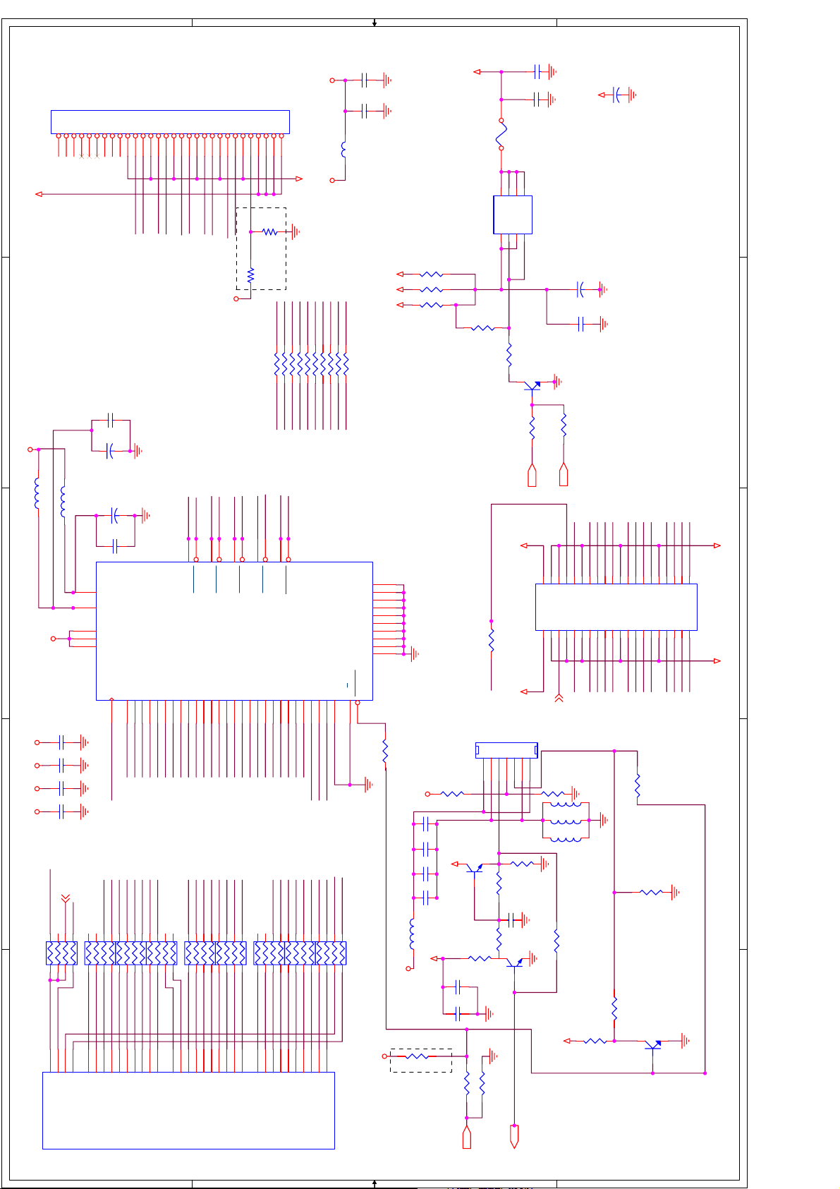
5 Schematic Diagram
AV33
R004 26.7
R003 26.7
3
2
1
FB_1K_OHM_200MA
0.1uF
C006
0.1uF
C005
TP027
VCCDVCCD
VCCD
VCCD
R007
R006
VCCD
2
2
4.75K
4.75K
3
3
TP028
R008
R009 26.7
VCCD
U001
4.75K
8
R010 26.7
VCC
D003 BAV99L
D002 BAV99L
123
VCLK
GVCK
1
1
NC1
AV33
0.1uF
C008
NC2
SCL
R013 26.7
R012 26.7
24LC21A
DATA2m
D005 srv05-4
DATA2p
3
2
1
DATA0p
DATA1m
DATA1p
DATA0m
4
5
6
4
NC3
GND
SDA
567
CLKp
R015 26.7
DO NOT STUFF
CLKm
VCCD
1
VCCSW
6FKHPHIRUGLJLWDOERDUGSDJHV
3
D004BAV70L
2
D5V
0.1uF
C007
1234567891011121314151617181920212223
33
P001
SHELL1
NC1
31
DATA2-
DATA4-
DATA2+
DATA2/4_SHLD
DATA4+
DDC_CLK
A_VSYNC
DDC_DATA
DATA1-
DATA3-
DATA1+
DATA1/3_SHLD
+5V
GND
DATA3+
DATA0-
DATA0+
H_PLUG_DET
24
CLK-
CLK+
DATA5-
DATA5+
CLK_SHLD
DATA0/5_SHLD
2526272829
A_RED
A_BLUE
A_HSYNC
A_GREEN
34
30
SHELL2
A_GND1
A_GND2
NC2
32
DVI_V
Page 20

R044
47k
of
D007BAV99L
1
AU-5V
2
3
2
D006BAV99L
3
1
1
PCR
PCL
R045
47k
C03710uf
D-L
C04010uf
D-R
1
<Variant Name>
415Monday, October 25, 2004
AU-5V
1 2
1
2
3
1 2
13
3
J002
2
D008BAV99L
3
2
1
AU-5V
D010BAV99L
3
3
2
1
AU-5VAU-5VAU-5V
HDR1
2
4
PHONEJACK STEREO
HDL1
HDL1DVIL
1
3
J004
R043
R042
47k
47k
AU-5V
AU-5V
AU-5V
AU-5V
AU-5V
AU-5V
AU-5V
AU-5V
R046
R047
R050
R051
R049
R053
R052
R048
X
Y
U005
X0X1X2X3Y0Y1Y2Y3INHAB
121415
11
22k
22k
22k
22k
22k
22k
22k
22k
10uf
12
12
10uf
12
12
15246109
10uf
12
12
12
12
4052
R055
R059
R061
R060
R058
R057
R056
R054
22k
22k
22k
22k
22k
22k
22k
22k
Confidential
2
900-0254-00 Trinity Production Reference Design A
A
Title
Size Document Number Rev
Date: Sheet
Audio Processor and Amplifiers
3
CONNECTOR COAX-J
C036
C041 10uf
C038
C039 10uf
C045 10uf
C042
C043 10uf
DVIR
DPF_L
C044 10uf
HDR1
PCR
1
1
SW1
DPF_R
SW2
4
5
DVIL
DVIR
4
D009BAV99L
3
2
D011BAV99L
3
2
1
1
DVIR HDR1
2
4
5
J003
R041
R040
47k
47k
DVIL
PCL
HDL1
DPF_L
1
AU-5V
10uf
3
C035
12
D024BAV99L
3
2
L009 25uH
VCCSW
AU-5V
AU-5V
D023BAV99L
3
2
CONNECTOR COAX-J
D D
C C
B B
A A
Page 21

of
515Monday, October 25, 2004
1
1
Confidential
0.1uF
C082
0.1uF
V33SW
V33SW
V18SW
V18SP
C081
0.1uF
C080
0.1uF
C079
0.1uF
C078
0.1uF
C077
0.1uF
C076
0.1uF
C075
M12
M11
M10
L13
K13
J13
H13
G13
F13
E13
D13
D12
D11
D10
L12
L10
J12
G12
E12
E11
G6
F5
E5
E7
J6
J5
H5
E6
E8
J2
J1
M8
M4
M5
M6
L4
L5
L6
L7
L8
E9
G8
H4
G4
M7
V33D14
V33D13
V33D12
V33D11
V33D10
V33D9
V33D8
V33D7
V33D6
V33D5
V33D4
V33D3
V33D2
V33D1
V18D9
V18D8
V18D7
V18D6
V18D5
V18D4
V18D3
V18D2
V18D1
V18SP
V18P3
V18P2
V18P1
V18A5
V18A4
V18A3
V18A2
V18A1
V33ADC8
V33ADC7
V33ADC6
V33ADC5
V33ADC4
V33ADC3
V33ADC2
V33ADC1
V33A5
V33A4
V33A3
V33A2
V33A1
PW3300 POWER
U008D
PW3300
GND44
J9
GND43
L11
GND42
K12
GND41
K11
GND40
J11
GND39
H9
GND38
H12
GND37
H11
GND36
G9
GND35
G11
GND34
F9
GND33
F11
GND32
F12
GND31
E10
GND30
K10
GND29
J10
GND28
H10
GND27
G10
GND26
F10
GND25
F8
GND24
F6
GND23
F7
GND22
J4
GND21
J3
GND20
H6
GND19
H7
GND18
H8
GND17
G5
GND16
F4
GND15
E4
GND14
M9
GND13
G7
GND12
H3
GND11
H2
GND10
H1
GND9
K4
GND8
K5
GND7
K6
GND6
L9
GND5
K7
GND4
K8
GND3
K9
GND2
J7
GND1
J8
V33ADC
L011
2
FB_1K_OHM_200MA
V33AV18A
C049
47uF_E
V33A
12
4
U007 LM1117
0.1uF
C048
0.1uF
C053
R065 825
V33ADJV18ADJ
ADJ
Vo4
Vo2
Vin
1
2
3
R064 499
0.1uF
C052
V18SW
V18SPV18P
VCCSW V33A
3
V18P
V18SP
0.1uF
C074
0.1uF
C073
0.1uF
C072
0.1uF
C071
0.1uF
C070
0.1uF
C069
0.1uF
C068
0.1uF
C067
0.1uF
C066
0.1uF
C065
0.1uF
C064
0.1uF
C063
V18A
0.1uF
C062
0.1uF
V33ADC
C061
0.1uF
C060
0.1uF
C059
0.1uF
C058
0.1uF
C057
0.1uF
C056
0.1uF
C055
0.1uF
C054
V18PV33ADC
V18A
V33A
L010
FB_1K_OHM_200MA
V18A
4
V18A
VCCSW
4
U006 LM1117
C047
12
0.1uF
C046
Vo4
L012
FB_1K_OHM_200MA
47uF_E
ADJ
1
Vo2
2
Vin
3
0.1uF
C051
R063 357
R062 825
0.1uF
C050
V33A
900-0254-00 Trinity Production Reference Design A
B
Title
Size Document Number Rev
Date: Sheet
Regulators and Capacitors for PW3200
2
3
4
5
D D
C C
B B
A A
5
Page 22

of
<Variant Name>
615Monday, October 25, 2004
1
GTXD
GRXD
A[19:1]
D[15:0]
ROMWEn
ROMOEn
1
Confidential
900-0254-00 Trinity Production Reference Design A
B
PW318 Miscellaneous IO and Circuitry
Title
Size Document Number Rev
Date: Sheet
R093
4.75K
V33
R092 1.00K
NMI1
NMI
1 4
0.1uF
C086
SW2
2 3
SW_MOM_4P
2
3
4
D7
D11
A16
ADC1
V6
R088 0
KEY2
D9D1D10
C16
ADC2
V5
C202
AFT
B15
D9
ADC3
TP004
18pF
C201
D10
D13
D14
D12
B16
D13
B14
D11
D12
D13
TDO
TMS
Y21
W21
TDI
TDO
TMS
12
JP001
PWON
18pF
R089 10.0K
V33
D15
A14
A15
A12A9B9
RD
WR
D14
D15
TCK
TDI
TRST
Y22
AA21
AA22
AB22
TRSTn
TCK
34
56
78
910
S_HDR_5X2
V33
A13
C13
CS0
ROMOE
ROMWE
JTAGSEL
TESTMODE
ADR24B
W22
AB21
ADR24B
R090 nc
NMI
B13
Y8
NMI
CS1
ANLGTST
EXTRSTEN
Y6
AB8
R091 0
DO NOT STUFF
D5
D6
D2
D3D8D4
B7A8B10
A19
A20
A21
PORTA6
PORTA7
W10
LED
PWM2
R076 10.0K
LED-OUT
D0
B17
D14
E9
D0D1D2D3D4D5D6D7D8
A22
A23
U002D
PW118
PORTB0
PORTB1
PORTB2
PORTB3
Y10
AB9
W11
AA11
AA12
TEMP
R077 10.0K
R078 10.0K
SW1
SW2
P_ON
V25
D17
C17
Misc
PORTB4
PORTB5
PORTB6
Y11
W12
R079 47
R081 47
SMXJ
DIPB/OE
LVDSON
R082
NC
R080
C200
18pF
D16
D15
PORTB7
Y12
R083 47
CONTRAL
NC
SCL
TEMP
10.0K
C14
ADC0
AA6
R086 0
KEY1
SDA
C15
AB7
A4
A3
A7
A2
A5
D12
B12
A10
C12
A6
D11
E12
C11C8A11C9C10D8D7B8C7
2
A1A2A3A4A5A6A7A8A9
RXD
TXD
XI
XO
RESET
V7
W7
Y13
AA8
U09
PT7M7809
2
1
nc
R067
2
1
V33
SW_MOM_4P
SW1
1 4
R072
2.21K
RESET
RSTn
2 3
V33
nc
3
3
R066
3
C084
1 2
Y001XTAL14.31818
R073 1.00M
DO NOT STUFF
R071 NC
R069 NC
0
0
R070
R068
4
VCCSW
IIC1
123
4
C083
V33
XTALIN
18pF
18pF
XTALOUT
R074
RXD
10.0K
W13
TXD
CON4
A14
A11A1A16
A10
A12
A10
A11
A12
A13
IRRCVR0
IRRCVR1
PORTA0
AB13
AA13Y9AB11
R075 47
SDA
TP002
IR1
C085
18pF
R174 100
B11D9A7
A14
A15
PORTA1
PORTA2
AA9
AA10
SCL
RESETn
A17
A16
A17
A18
PORTA3
PORTA4
PORTA5
AB12
AB10
MUTE
PWRON
DPWON
D10
W9
A15
A18A8A19
A13
A9
LED-OUT
R085 47
R084
TEM1
R087 47
12345
V12
IR
CON5
5
D D
C C
B B
A A
5
Page 23

46
47
45 HEADER
JP002
1
qqq
qqq1
123456789101112131415161718192021222324252627282930313233343536373839404142434445
D8D9D10
D12
D11
D13
D14
D15
SMXJ
DATACLK
IN1HS
DIPB/OE
IN1VS
D7
D6D5D4D3D2
D0
D1
Confidential
of
<Variant Name>
715Monday, October 25, 2004
1
SMXJ
R094 NC
GRXD
W3
SCL
R095 47.5
AB1
R096 47.5
R097 NC
SDA
GTXD
DIPB/OE
R098 47.5
DE_SM
VCCSW
DPF_R
DPF_R
DPF_L
DPF_L
900-0254-00 Trinity Production Reference Design A
B
PW318 Input Ports 0 and 1
Title
Size Document Number Rev
Date: Sheet
2
RP012
IN1CMP
IN1CLK
U3
R4
7
47R
1 823
DE_SM
DATACLK
IN1CST
IN1PEN
IN1VBI
Y4
AA1
6
4 5
IN1VS
IN1HS
IN1HS
IN1AHS
AB6
AB2
IN1VS
IN1FLD
Y3
R099 47.5
IN1FLD
IN1R0
AA4
Y1
IN1R1
IN1R2
W4
IN1R3
W1
AB5W2AA5
IN1R4
IN1R5
IN1R6
IN1R7
AA3
U002B
IN1R8
T3
AB4
PW118
IN1R9
V3
Input Port 1
IN1G0
R1
RP013 47R
IN1G1
IN1G2
AB3
4 5
R2
6
D1D3D0
IN1G3
IN1G4
T2
7
D2
IN1G5
T1
1 823
IN1G6
V4
4 5
D5D4D7
IN1G7
AA2
6
Y5
7
D6
IN1G8
IN1G9
U1
1 823
IN1B0
R3Y2U2
47R
RP014
RP01547R
IN1B1
1 823
D8
IN1B2
IN1B3
V1
7
D9
IN1B4
P4U4V2
6
4 5
D10
D11
IN1B5
1 823
D12
IN1B6
IN1B7
W5
7
D13
D14
P5
6
IN1B8
IN1B9
T4
4 5
D15
47R
RP016
ALTCLK
TP030
TP005
3
IN0CMP
IN0CST
2
3
K3
4
5
K2
IN0CST
IN0CMP
IN0CLK
IN0PEN
L4L5L3
IN0CLK
IN0PEN
D D
IN0VBI
IN0AHS
L1
IN0VBI
IN0AHS
IN0HS
J3
IN0HS
IN0VS
J1
IN0VS
IN0FLD
M4
IN0FLD
IN0RE[9:0]
IN0RE0
IN0RE1
A6
B6C6A5
IN0RE0
IN0RE1
IN0RE2
IN0BE[9:0]
IN0GE[9:0]
IN0RE2
IN0RE3
B5C5A4
IN0RE3
IN0RE4
IN0RE4
IN0RE5
IN0RE5
IN0RE6
IN0RE6
IN0RE7
B4
D6
IN0RE7
IN0RE8
IN0RE8
IN0RE9
C4
IN0RE9
IN0GE0
IN0GE1
A3
D5
IN0GE0
IN0GE1
IN0GE2
IN0GE3
B3
D4F5N3
IN0GE2
IN0GE3
IN0GE4
IN0GE5
IN0GE4
IN0GE5
C C
U002A
IN0GE6
IN0GE7
E6
B2
IN0GE6
IN0GE7
PW118
IN0GE8
IN0GE9
E5
D3
IN0GE8
IN0GE9
Input Port 0
IN0BE0
IN0BE1
C3C2D2E3N4
IN0BE0
IN0BE1
IN0BE2
IN0BE2
IN0BE3
IN0BE3
IN0BE4
A2E4A1
IN0BE4
IN0BE5
IN0BE5
IN0BE6
IN0BE6
IN0BE7
IN0BE7
IN0BE8
F4
B1
IN0BE8
IN0BE9
IN0BE9
G5
IN0RO0
IN0RO1
IN0RO2
C1
H4
IN0RO2
IN0RO[9:2]
IN0GO[9:2]
IN0RO3
IN0RO4
E2
P2
D1
IN0RO3
IN0RO4
IN0RO5
IN0BO[9:2]
IN0RO5
IN0RO6
G4
M2
IN0RO6
IN0RO7
B B
IN0RO7
IN0RO8
F3
M3
IN0RO8
IN0RO9
IN0RO9
H3
IN0GO0
IN0GO1
P1E1K5
N2
IN0GO2
IN0GO2
IN0GO3
IN0GO3
IN0GO4
IN0GO4
IN0GO5
F2N1F1
IN0GO5
IN0GO6
IN0GO6
IN0GO7
J4
IN0GO7
IN0GO8
IN0GO8
IN0GO9
G3
IN0GO9
IN0BO0
G2
M1
IN0BO1
IN0BO2
L2
G1
IN0BO2
IN0BO3
IN0BO3
IN0BO4
K1
H2
IN0BO4
IN0BO5
IN0BO5
IN0BO6
K4
H1
IN0BO6
IN0BO7
IN0BO7
IN0BO8
J2
P3
IN0BO8
IN0BO9
A A
4
IN0BO9
5
Page 24
LVDS Output
Connector
1234681012141618202224262830
DF14A-30P-1.25H
1
PANEL_POWER
2
V33
L002
L003
7
911131517192123252729
5
TXE2p
C018
C017
TXE0m
0.01uF
10uF_6V
TXE0p
TXE1m
TXE1p
TXE2m
TXECm
TXECp
C031
33R FB
5
D2
G2
4
3
4K7
R033
0.1uF
C030
0.1uF
SI9953ADY
Q003
DTC144EKA
1
LVDSON
LVDSON
C034
22uF/16V
PANEL_POWER
1
C033
22uF/16V
C032
0.1uF
2
NC
R035
DPWON
2
0.1uF
C022
V33ATV33
P002
L004
GND
R186
R185
NC
NC
TXE2p
TXE2m
TXECp
TXECm
TXE1mRDB5
TXE0m
TXE0p
R177 0
R178 0
R179 0
R180 0
R181 0
R182 0
R183 0
R184 0
RDB2
RDB3
RDB4 TXE1p
RDB6
RDB9
RDB8
RDB7
TXE3p
TXE3m
V33
0.1uF
C021
FB_420_OHM_200MA
V12
VCCSW
TXE3m
TXE3p
R016 0
RDG3
RDG2
R017 0
V33
B VERSION PW218 CAN DIRECTLY OUTPUT LVDS SIGNAL
R020
PANEL_POWER
F001
876
D1D1D2
S1G1S2
U004
R026
123
nc
R031 1K
Panel Power Voltage Selection
R022
nc
R021
nc
0
3
4
5
FERRITE BEAD
V33
0.1uF
C016
0.1uF
C015
0.1uF
C014
0.1uF
C013
V33 V33 V33 V33
DCLK3
DCLK1
DVS
RP001
47R
6
7
4 5
RDCLK
RDVS
V17
V19
V18
DVS
DHS
DCLK
C020
FERRITE BEAD
C019
34
44
26
9
1
DCLK1
DR3
DR2
RP002
47R
6
7
4 5
1 823
RDR1
RDR3
RDR2
RDR0
AB14
AB15
AB16
AA19
DR0
DR1
DR2
DEN
CLKIN
31
1 823
AB17
DR3
PVCC
VCC3
VCC2
VCC1
DR4
RP003
1 823
RDR4
AA14
10uF_6V
0.01uF
OVCC
TXIN0
TXIN1
5152545556
DR3
DR2
DR6
DR5
47R
6
7
RDR6
RDR5
AB18
AA15
DR4
DR5
DR6
TXIN2
DR5
DR4
DR7
DR8
RP004
4 5
4 5
RDR8
RDR7
Y14
W14
DR7
U002C
TXIN3
TXIN4
DR6
DR7
DR9
47R
6
RDR9
W20
DR8
DR9
PW118
TXIN6
DR8
7
RDG0
Display Port
TXIN5
TXIN27
23467
50
DR9
1 823
RDG1
AA16
AA17
DG0
DG1
TXE0m
TXE0p
47
48
TXOUT0
TXIN7
DG2
DG3
DG3
DG2
RP005
47R
6
4 5
RDG2
RDG3
AB19
Y15
DG2
TXE1p
45
TXOUT1
TXOUT0
TXIN8
TXIN9
TXIN12
111214
DG4
DG5
DG5
DG4
7
1 823
RDG4
RDG5
V20
V14
DG3
DG4
DG5
TXE1m
46
TXOUT1
U003
TXIN13
DG6
DG7
DG6
DG7
RP006
47R
7
1 823
RDG7
RDG6
AA18
Y16
DG6
TXE2p
41
TXOUT2
TXIN10
TXIN14
8
DG8
DG8
6
RDG8
W15
DG7
DG8
TXE3m
TXE3p
TXE2m
TXECp
37
39
42
38
TXOUT3
TXOUT2
TXOUT3
TXCOUT
DS90C385A
TXIN11
TXIN15
TXIN18
TXIN19
TXIN20
TXIN21
10
15
192022232425272830
DB2
DB4
DB3
DB6
DG9
DB5
DG9
DB3
DB2
RP007
47R
6
7
4 5
1 823
4 5
RDB1
RDB3
RDB0
RDG9
RDB2
Y17
Y18
W16
V21
AB20
DB0
DB1
DB2
DB3
DG9
TXECm
40
TXCOUT
TXIN22
16
DB7
DB8
DB4
DB5
RP009
47R
6
4 5
RDB4
RDB5
AA20
Y19
DB4
TXIN16
TXIN17
18
DB9
DHS
DB6
DB7
7
RDB6
RDB7
W17
DB5
DB6
TXIN24
TXIN25
DVS
DB8
RP011
1 823
1 823
RDB8
W18
Y20
DB7
DB8
TXIN26
DEN
DB9
47R
7
RDB9
W19
DB9
TXIN23
DHS
DEN
6
RDHS
4 5
RDEN
R_F
17
PGND2
PGND1
OGND3
OGND2
OGND1
GND5
GND4
GND3
GND2
GND1
PWRDN
32
200
R018
V33
DG9
DG8
DG7
DG6
NC
R038
3
DG5
DG4
DG3
DG2
R039
Q004
10.0K
1
DR9
DR8
DR7
DR6
MMBT3904L
2
DR5
DR4
DR3
DR2
40
39
87089-40
GND GND
3
4
5
DB7
DB5
DB3
DB9
DHS
DE
PANEL_POWER
35
33
49
43
36
53
29
21
13
5
R023
V33
C026
0.1uF
C025
0.1uF
C024
0.1uF
C023
0.1uF
L005
33R FB
VCCSW
V12
C028
0.1uF
C027
0.1uF
R019 nc
DO NOT STUFF
P003
NC
VCCSW
DEN
1234567
CONN PCB 7
1234567
Q001
NC
1
R025
6.8K
R024 0
R027 10.0K
R028 0
2 3
R030
R029
Q002
246
8
101214161820222426283032343638
135791113151719212325272931333537
J001
DB8
DB6
DVS
DCLK3
PANEL_POWER
DCLK3
R034
10.0K
L00833R FB
L00733R FB
L00633R FB
10.0K
R032
0
C029
0.1uF
4.7K
1
DTC144EKA
NC
R199
2 3
R036
VCCSW
5.1K
DB4
DB2
470R
R037
D D
C C
DPWON
B B
PWM2
A A
Page 25

A
of
<Variant Name>
915Monday, October 25, 2004
1
V25
M13S128168A
U012
1
VDD1
18
VDD2
39156155
33
VDD3
VDDQ1
VREF
VDDQ2
VDDQ3
VDDQ5
VDDQ4
CKECKCK
444546
MMD1
MMD0
245810117
DQ0
DQ1
CAS
RAS
MMD3
MMD2
DQ2
WE
212223
MMD4
DQ3
CS
24
MMD9
MMD6
MMD8
MMD7
MMD5
135456575960626365
DQ4
DQ5
DQ6
DQ7
DQ8
UDM
UDQS
LDQS
LDM
16
20
474951
MMD11
MMD15
MMD12
MMD10
MMD14
MMD13
DQ9
DQ10
DQ11
DQ12
DQ13
DQ14
DQ15
VSS1
VSS2
A0A1A2A3A4A5A6A7A8A9A11
2930313235363738394041
6648346126458
52
VSS3
VSSQ1
VSSQ2
VSSQ3
A10/AP
A12
28
42
VSSQ5
VSSQ4
BA0
BA1
DDR400_SDRAM_128M
26
27
V25
M13S128168A
U013
1
18
VDD1
VDD2
39156155
33
VDD3
VREF
VDDQ1
VDDQ2
VDDQ3
VDDQ4
444546
MMD16
VDDQ5
CKECKCK
MMD18
MMD17
245810117
DQ0
DQ1
CAS
RAS
MMD19
MMD20
DQ2
DQ4
DQ3
CS
WE
212223
24
MMD25
MMD23
MMD21
MMD22
MMD24
MMD26
135456575960626365
DQ5
DQ6
DQ7
DQ8
DQ9
UDM
UDQS
LDQS
LDM
16
20
2930313235363738394041
474951
MMD27
MMD31
MMD29
MMD28
MMD30
6648346126458
DQ13
DQ14
DQ15
VSS1
VSSQ1
A10/AP
DQ10
DQ11
DQ12
A0A1A2A3A4A5A6A7A8A9A11
VSS3
VSS2
28
52
VSSQ2
A12
42
VSSQ4
VSSQ3
BA0
26
VSSQ5
BA1
27
Confidential
DDR400_SDRAM_128M
Title
1
B
DDR SDRAM for PW218
Size Document Number Rev
Date: Sheet
2
RMA0
RMA2
RMA1
RMA3
RMA4
RMA7
RMA6RMA5
RMA8
RMA9
RMA10
RMA12
RMA11
RMA0
RMA1
RMA3
RMA2
RMA4
RMA6
RMA5
RMA7
RMA9
RMA8
RMA11
RMA10
RMA12
2
RMA[12:0]
RMCK0
RMCK1
RMDM0RMDM0
RMBK0
RMBK1
RMDM2RMDM2
RMDM3RMDM3
RMDQS3RMDQS3
RMDQS2RMDQS2
0.1uF
C089
0.1uF
C088
0.1uF
C087
MVREF
R103
1K
3
RMA[12:0]
R102 1K
3
V25
0.1uF
V25
V25
V25
V25
V25
V25
V25 V25
C097
0.1uF
C096
0.1uF
C095
0.1uF
C094
0.1uF
C093
0.1uF
C092
0.1uF
C091
0.1uF
C090
RMRASn RMRASn
RMCASn RMCASn
RMCSn RMCSn
RMWEn RMWEn
RMA9
22R
MA5
MA4
7
B19
RMA6
6
MA6
J20
MA5
RMA7
4 5
MA7
F22
MA6
MA7
RMA8
RP030
22R
6
4 5
MA9
MA8
K19
K20
MA8
RMA10
RMA11
7
MA10
A20
MA9
MA10
1 823
MA11
G21
RMA12
RP031
22R
1 823
MA12
K18
MA11
MA12
7
RMBK1
RMBK0
6
4 5
MBNK1
MBNK0
M18
H22
MBNK0
RP032
4 5
MDM2
MBNK1
22R
MDM3
E20
MDM2
6
D20
MDM3
7
1 823
MDQS2
MDQS3
A22
G19
MDQS2
MDQS3
RMDQS1 RMDQS1
4 5
MDQS1
P22
MDQS0
MDQS1
U002F
RMA0
RP026
1 823
MA0
G22
PW118
RMA1
22R
7
MA1
L20
MA0
MA1
RMA2
6
MA2
L19
MA2
RMA3
RMA4 RMA5
RP028
4 5
MA3
J21
MA3
1 823
MA4
E22
RMCKn RMCK1n
RMCKE RMCKE
RMCK RMCK0n
R101 22
MCKn
U21
MCK
U20
MCK
MCKFBK
T19
A18
MCKE
MCKFBK
RP021
1 823
MRASn
B20
RP018
22R
1823
45
6
7
R100 22
4
M22
C22
MREFIN0
MREFIN1
MCK
V22
MMD[31:0]
22R
7
MCASn
A19
MRAS
MCAS
6
MWEn
A17
4 5
MCSn
B18
MWE
Main
MCS
Memory
RMDM1 RMDM1
RP023
22R
7
1 823
MDM1
MDM0
N22
MDM0
Port
RMDQS0 RMDQS0
6
MDQS0
N21
P21
MDM1
V25
V25
V25V25
V25 V25
V25
V25
0.1uF
C105
0.1uF
C104
0.1uF
C103
0.1uF
C102
0.1uF
C101
0.1uF
C100
0.1uF
C099
0.1uF
C098
4
MD0
MD1
MD2
MD3
MD4
MD5
MD6
MD7
MD8
MD9
MD10
MD11
MD12
MD13
MD14
MD15
MD16
MD17
MD18
MD19
MD20
MD21
MD22
MD23
MD24
MD25
MD26
MD27
MD28
MD29
MD30
MD31
R19
MD3
1823
MMD3
R20
R21
MD5
MD4
RP019
22R
45
6
MMD5
MMD4
D D
R22
MD6
7
MMD6
P19
MD7
1823
MMD7
L22
MD8
RP020
4 5
MMD8
T20
T21
T22
MD0
MD1
MD2
RP017
22R
5
45
6
7
MMD1
MMD0
MMD2
N20
MD9
22R
6
MMD9
M19
MD10
7
MMD10
K22
MD11
1 823
MMD11
M20
MD13
MD12
RP022
22R
45
6
MMD12
MMD13
M21
L21
MD14
7
MMD14
K21
MD15
1823
MMD15
H20
MD16
MD17
RP024
22R
45
6
MMD17
MMD16
F21
D22
MD19
MD18
7
MMD19
MMD18
H19
1823
E21
G20
MD20
MD21
RP025
22R
45
6
MMD20
MMD21
D21
MD22
7
MMD22
C21
MD23
1823
MMD23
B21
MD24
MD25
RP027
22R
1823
7
MMD24
MMD25
F19
E19
MD26
6
MMD26
C20
MD28
MD27
RP029
45
MMD27
MMD28
45
D19
C19
MD29
22R
6
MMD29
C C
E18
MD30
7
MMD30
D18
MD31
1823
MMD31
RMDQS0
MDQS0
TP006
TP007
MD0
TP008
MD31
TP010
MMD31
TP0011
RMCK
RMA0
TP012
RMCKn
TP014
TP013
RMCASn
TP016
TP015
TP018
5
B B
A A
MMD0
TP009
Page 26

of
<Variant Name>
C135
100uF/16V
10V
C115
100uF/16V
C110
100uF/16V
1
10V
V18
10V
GND
V25
C134
C114
C109
0.1uF
0.1uF
GND
GND GND
GND
0.1uF
GND
Confidential
914Monday, October 25, 2004
1
25uH
4
TAB
U015
VIN VOUT
lt1084-1.8V
3 2
L018 25uH
1
GND/ADJ
C116
nc
R111
100uF/16V
nc
C117
R112 0
GND
L016 25uH
nc
1
C111
R106
100uF/16V
nc
C112
R107 0
4
TAB
GND/ADJ
U014
VIN VOUT
2
lt1084-3.3V
3 2
4
TAB
U016
VIN VOUT
lt1084-2.5V
3 2
L020
GND/ADJ
1
C152
nc
R113
100uF/16V
900-0254-00 Trinity Production Reference Design A
nc
C153
B
Regulators and PW318 Capacitors
Title
Size Document Number Rev
Date: Sheet
R114 0
MH4
MH8
MH7
2
MH1
GND
GND
FID4
L019
V18 V18 V18 V18 V18 V18 V18 V18 V18V33 V33 V33 V33
V33
33R FB
FID3
FID2
VIO10
VIO9
VIO8
VIO7
VIO6
VIO5
VIO4
VIO3
VIO2
VIO1
VDD9
VDD8
VDD7
VDD6
VDD5
VDD4
VDD3
VDD2
VDD1
VCC9
VCC8
VCC7
VCC6
VCC5
VCC4
VCC3
VCC2
VCC1
VAA33
VDD21
VDD20
VDD19
VDD18
VDD17
VDD16
VDD15
VDD14
VDD13
VDD12
VDD11
VDD10
VCC11
VCC10
MVAA18
DVAA18
PVAA18
FID1
Power and Ground
U002E
PW118
GND42
GND41
GND40
GND39
GND38
GND37
GND36
GND35
GND34
GND33
GND32
GND31
GND30
GND29
GND28
GND27
GND26
GND25
GND24
GND23
GND22
GND21
GND20
GND19
GND18
GND17
GND16
GND15
GND14
GND13
GND12
GND11
GND10
GND9
GND8
GND7
GND6
GND5
GND4
GND3
GND2
GND1
0.1uF
C156
0.1uF
C151
V13
0.1uF
C150
0.1uF
C149
0.1uF
C148
0.1uF
C147
0.1uF
C146
0.1uF
C145
0.1uF
C144
0.1uF
C141
FB_1K_OHM_200MA
V33 V33
V18 V25
0.1uF
C140
0.1uF
C139
0.1uF
C138
0.1uF
C137
0.1uF
C136
V18MV
L021
FB_1K_OHM_200MA
V12
V11
U17
T5
R5
J5
H5
V33AA
E8
E7
U5
U22
T18
R18
P20
P18
N18
L022
J22
J19
J18
H21
H18
G18
F20
F18
F17
E17
E15
E14
E13
C18
A21
V16
V15
V10
V9
N5
M5
L18
F6
E16
E11
E10
U19
AA7
Y7
0.1uF
V18PD
C155
0.1uF
C154
L023
FB_1K_OHM_200MA
V18
L017
L015
33R FB
V33
33R FB
VCCSW
VCCSW V33
0.1uF
V25 V25 V25 V25 V25 V25V25 V25 V25 V25 V25
C133
0.1uF
C132
0.1uF
C131
0.1uF
C130
0.1uF
C129
0.1uF
C128
0.1uF
C127
0.1uF
C126
0.1uF
C125
0.1uF
C124
0.1uF
C123
0.1uF
C122
0.1uF
C121
0.1uF
C120
0.1uF
C119
0.1uF
C118
3
C107
470UF_E
12
C108
470UF_E
12
VCCSW
V12
L014 4.7uH
L013 25uH
P_ON
123456789
123456789
Q005A
IRF7314
1
2
AV18ON
499
CONN PCB 9
V18SW
8
7
Q006
NPN
1
V33SW
Q005B
IRF7314
6
3
V33
5
4
C113
0.1uF
AV33ON
Q007
2 3
R108 10.0K
NPN
2 3
1
PWR1
4
V18V33
C106
0.1uF
R104 10.0K
R105
DO NOT STUFF
5
R109 499
R110 4.99K
V33 V33 V33 V33 V33
FID7
1
1
1
1
FID6
1
1
FID5
1
1
FID8
3
W8
W6
V8
U18
P14
P13
P12
P11
P10
P9
N19
N14
N13
N12
N11
N10
N9
M14
M13
M12
M11
M10
M9
L14
L13
L12
L11
L10
L9
K14
K13
K12
K11
K10
K9
J14
J13
J12
J11
J10
J9
B22
4
5
PWRON
D D
C C
B B
A A
Page 27

INT1
TP021
TP022
TP023
TP024
TP025
TP026
1
VCCG
TP020
TP019
of
<Variant Name>
10 14Thursday, October 28, 2004
1
R115 4.75K
R118 47
R117 47
R126 47
R119 47
R120 47
R121 47
R123 47
R124 47
R130 10.0K
MCL
B1
C10
A9C9B7C7D7A6B6C6D6
GPIO0
GPIO2
GPIO9
EXTINT
GPIO10
GPIO11
GPIO12
GPIO13
GPIO14
SA5
adra3
GPIO15
SA2
SCL
A3A2A1
B3
18pF
18pF
SCL
SYSCLKT
U008C PW3300
2
XIN
SA6
XIN
XOUT
A4
A5
adra1
adra2
XOUT
C158
Y002XTAL27.000
R116 1.50M
C157
B2
R125 0
SDA
R127 0
SDA
NC1
NC2
HDCPSCL
HDCPSDA
B5
B4
0
R128 0
R129
GSCL
GSDA
R197
R195
D4D3D2
MCL
PW3300 GPIO
RESET
D1
R132 10.0K
NC
0
adra2 adra3
R198
R196
44
38
25
13
7
1
V33SW
V33SW
0
NC
DMD[15:0]
NC
adra1
R194
0
R193
3
V33SW V33SW V33SW
DMD1
DMD2
DMD0
DMD3
235689111239404243454648
D0D1D2D3D4D5D6D7D8
VCC6
VCC5
VCC4
VCC3
VCC2
VCC1
CLK
CKE
A0A1A2A3A4A5A6A7A8A9A10
2122232427282930313220
35
34
DMA2
DMA1
DMA0
DMCLK
R9
P12
N12
P13
FSA0
FSA1
FSCLK
U008B PW3300
FSD0
FSD1
FSD2
FSD3
P5N5P6N6P7N7P8
DMD4
DMD3
DMD2
DMD1
DMD0
DMD4
DMA3
N13
FSA2
FSD4
DMD5
DMD5
DMA4
R13
FSA3
FSD5
DMD6
DMD6
DMA5
FSA4
FSD6
DMD7
DMD9
DMD10
DMD7
DMD8
D9
D10
DMA9
DMA8
DMA7
DMA6
R12
T12
R11
T11
R10
FSA5
FSA6
FSA7
FSA8
FSA9
FSD7
FSD8
FSD9
FSD10
FSD11
N8
R8T8R7T7R6T6R5
DMD11
DMD10
DMD9
DMD8
DMD11
DMD12
D11
D12
A11
19
DMA10
N11
T10
FSA10
FSA11
FSD12
FSD13
DMD13
DMD12
DMD14
DMD13
D13
U017
DMBA0
N10
FSD14
T5
DMD14
DMD15
DMD15
49
D14
D15
SDRAMX16M_TSOP50
1436171615
DMDQM
T9
P11
FSBANK0
FSBANK1
FSD15
33
DQML
DQMH
FSDQM
37
NC1
NC2
RAS
DMCASn
DMRASn
N9
P10
FSRAS
CASWECS
FSCAS
GND6
GND5
GND4
GND3
GND2
GND1
18
DMWEn
P9
FSWE
PW3300 SDRAM
Confidential
50
47
41
26
10
4
V33SW V33SW V33SW V33SW V33SW V33SW
900-0254-00 Trinity Production Reference Design A
B
ADC, PLL, Decoder, and 3D Comb Filter
Title
Size Document Number Rev
Date: Sheet
0.1uF
C171
0.1uF
C170
0.1uF
C169
0.1uF
C168
0.1uF
C167
0.1uF
C166
2
3
SDA
SCL
IN0RO[9:2]
IN0GO[9:2]
IN0BO[9:2] RESETn
IN0RE[9:0]
IN0GE[9:0]
IN0BE[9:0]
IN0PEN
IN0CLK
IN0HS
IN0AHS
IN0VS
IN0FLD
IN0VBI
ALTCLK
CVBSSOG
C164
1nF
CVBS
CVBS1
IN0RE5
IN0RE4
RP040
47R
7
1 823
DGRO4
DGRO5
J16
J15
DGRO4
DGRO5
RED2
GRN2
N1
N2
IN0RE7
IN0RE6
6
4 5
DGRO6
DGRO7
J14
K16
DGRO6
DGRO7
BLU2
SOG2
N4
N3
IN0RE9
IN0RE8
RP041
47R
7
1 823
DGRO8
DGRO9
K15
K14
DGRO8
DGRO9
RED3
P1
IN0GE0
6
4 5
DGGO0
L16
GRN3
P2
P3
IN0GE2
IN0GE1
RP042
1 823
DGGO1
DGGO2
L15
L14
DGGO0
DGGO1
BLU3
SOG3
P4
IN0GE3
IN0GE4
47R
6
7
DGGO3
DGGO4
M16
M15
DGGO2
DGGO3
RED4
R1
R2
IN0GE5
IN0GE6
RP043
4 5
1 823
DGGO5
DGGO6
M14
M13
DGGO4
DGGO5
GRN4
SOG4
R4
R3
IN0GE7
IN0GE8
47R
6
7
DGGO7
DGGO8
N16
N15
DGGO6
DGGO7
BLU4
IN0GE9
IN0BE0
IN0BE1
RP044
47R
1 823
4 5
DGBO0
DGBO1
DGGO9
N14
P16
DGBO0
DGGO8
DGGO9
HS2
VS2R2G2B2S2
T4
IN0BE2
6
7
DGBO2
P15
P14
DGBO1
DGBO2
L2
L3
IN0BE3
IN0BE4
RP045
1 823
4 5
DGBO3
DGBO4
R16
R15
DGBO3
DGBO4
M3
M2
IN0BE5
IN0BE6
47R
6
7
DGBO5
DGBO6
R14
T16
DGBO5
DGBO6
IN0BE7
IN0BE8
RP046
1 823
4 5
DGBO7
DGBO8
T15
T14
DGBO7
DGBO8
IN0BE9
47R
6
7
DGBO9
T13
DGBO9
ASPECT0
C3C4C2
4 5
R133 47.5
DGCLK1
G15
G16
DGCLK2
ASPECT1
ASPECT2
C1
RP047
4 5
R134 47.5
DGPEN
DGAHS
F16
F15
DGPEN
DGAHS
DGCLK1
REXT
47R
6
DGVS
DGHS
F14
DGHS
7
E16
1 823
R138 47.5
DGFLD
DPVBI
E15
B9D9A8B8C8
DGVS
DGVBI
DGFLD
R139 47.5
CVBSIN
ALTCLK1
A7
ALTPEN
ALTCLK1
R140 3.32K
D8
ALTVS
ALTHS
ALTAHS
ALTFLD
R141 0
0.18
R142 0
C165
123
4
CV1
CON4
PW3300 DATA PATH
4
IN0RE2
DGBE7
GRN1
SOG1
L1
IN0RE0DGRO0
RP039
BLU1
M1
47R
7
1 823
DGRO1 IN0RE1
G14
H16
DGRO0
DGRO1
HS1
T1T2T3
IN0RE3
6
4 5
DGRO2
DGRO3
H15
H14
DGRO2
DGRO3
VS1
IN0GO5
IN0RO2
IN0RO7
IN0RO5
IN0RO4
IN0RO6
IN0RO3
RP034
47R
RP033
47R
6
6
7
4 5
1 823
4 5
4
DGRE0
DGRE1
DGRE2
DGRE3
DGRE4
DGRE5
B10
A10
C11
B11
A11
C12
DGRE0
DGRE1
DGRE2
DGRE3
DGRE4
RX0P
RX1P
RX1M
RX2P
RX2M
U008A PW3300
F3
F2
E3
E2
G3
G2
IN0RO9
IN0RO8
7
DGRE6
DGRE7
B12
DGRE5
DGRE6
RX0M
1 823
A12
DGRE7
RXCP
F1
G1
IN0GO2
RP035
4 5
DGGE0
C13
DGGE0
RXCM
RTERM
E1
IN0GO4
IN0GO3
47R
6
7
DGGE1
DGGE2
DGGE3
B13
A13
DGGE1
DGGE2
IN0GO6
RP036
1 823
4 5
DGGE4
C14
B14
DGGE3
IN0GO7
IN0GO8
47R
6
7
DGGE6
DGGE5
A14
A15
DGGE4
DGGE5
IN0GO9
1 823
DGGE7
A16
DGGE6
DGGE7
IN0BO2
IN0BO3
RP037
47R
7
1 823
DGBE0
DGBE1
B16
B15
DGBE0
DGBE1
FILT
K3
IN0BO4
IN0BO5
6
4 5
DGBE2
DGBE3
C16
C15
DGBE2
DGBE3
COAST
C5
IN0BO6
IN0BO7
RP038
47R
7
1 823
DGBE4
DGBE5
D16
D15
DGBE4
DGBE5
CLAMP
D5
IN0BO8
IN0BO9
6
4 5
DGBE6
DGBE7
D14
E14
DGBE6
RED1
K2
K1
nc
R137
23.7K
REXT
ASPC0
C161
CVBS
CVBSSOG
C162 nc
PWRED4
C163
0.1uF
C160
FILT
C159
39nF
FLT1
3.9nF
RX1m
RX2p
RX0p
RX2m
RX1p
RX0m
R122 3.32K
RXCp
RXCm
5
ASPC1
R136
R135
3.92K
3.92K
5
R131 3.32K
RX2p
RX0p
RX1m
RX2m
RX1p
RX0m
RXCm
RXCp
V18P
IN0CST
IN0CMP
RAIN
GAIN
BAIN
PCSOG
HSYNC
VSYNC
HDY1
HDCR1
HDCB1
HDSOG1
2300Y
SSOG
2300C
D D
C C
B B
A A
Page 28
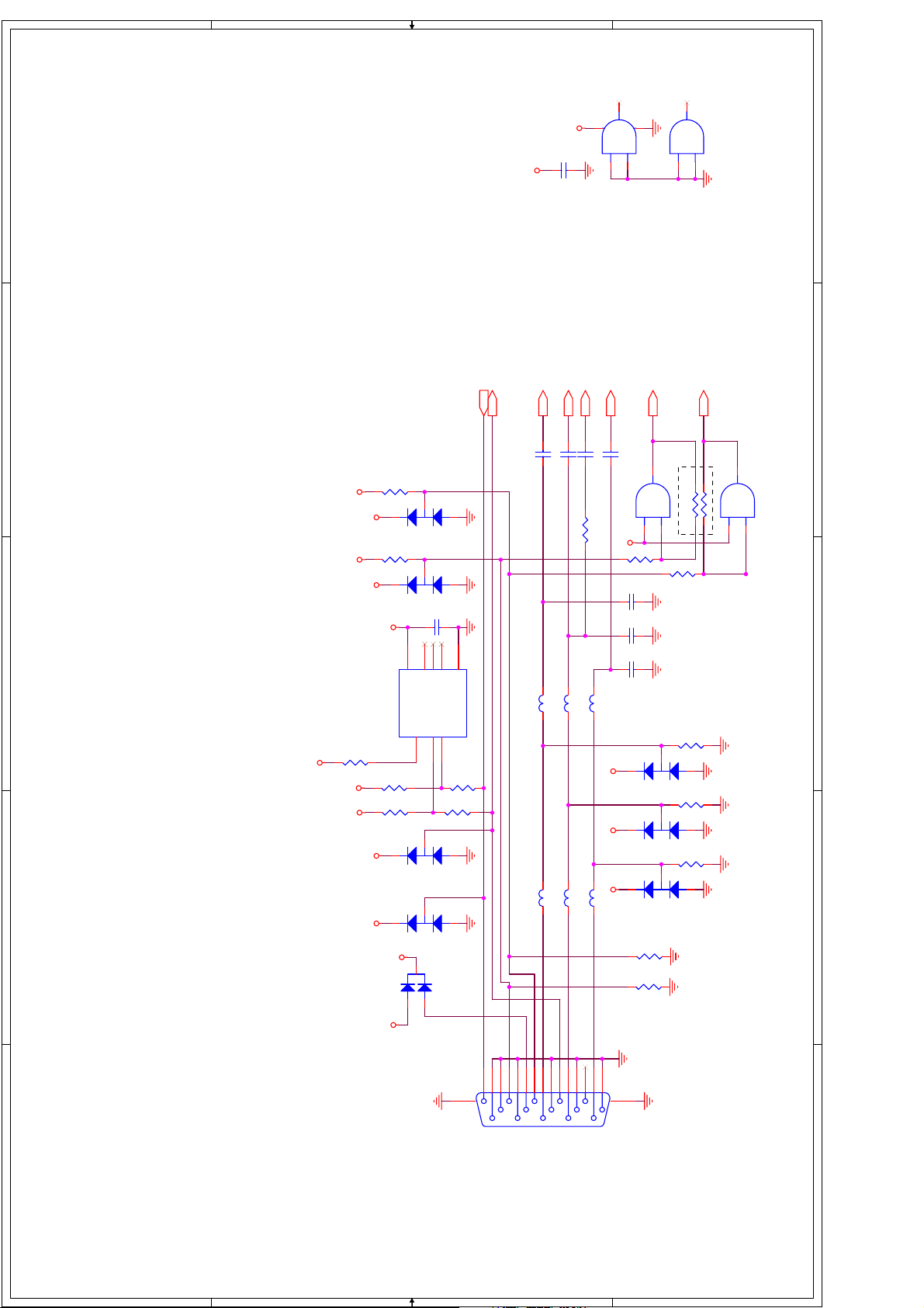
3
U019A
74ACT08A
VCCG
VCCG
0.1uF
C175
1
2
1
11
U019D
7 14
74ACT08A
13
12
of
<Variant Name>
11 14Monday, October 25, 2004
1
Confidential
900-0254-00 Trinity Production Reference Design A
B
Graphics and HDMI Input Connectors
Title
Size Document Number Rev
Date: Sheet
GTXD
GRXD
2
R147
VCCG
VCCG
2
R146
2
2.21K
D016BAV99L
3
2.21K
D015BAV99L
3
0.1uF
C172
1
1
VCCG
VCCG
BAIN
C173
0.18uF
GBLUC
VCCG
3
GVCK
R143
VCCG
4.75K
VCCG
VCCG
VCCG
4
VCCG
8
VCC
U018 24LC21A
R144
4.75K
R145
4.75K
D014BAV99L
2
D013BAV99L
2
VCCG
3
D012
1
123
VCLK
3
3
2
NC1
NC2
SCL
567
BAV70L
NC3
SDA
R149
R148
4
GND
1
1
4.75K
4.75K
L025
FB_11_OHM_500MA
FB_11_OHM_500MA
GBLUF
L024
FB_11_OHM_500MA
FB_11_OHM_500MA
GAIN
PCSOG
C176
1nF
C174
0.18uF
PCRS
GREDC
GGRNC
R150 3.32K
L027
L029
FB_11_OHM_500MA
V33ADC V33ADC C177
GGRNF
V33ADC
L028
FB_11_OHM_500MA
L026
RAIN
0.18uF
R151
47
VCCG
C180
C179
C178
2
2
2
VSYNC
8
U019C
74ACT08A
DO NOT STUFF
9
10
R154
12pF
12pF
12pF
R157
D019BAV99L
3
R156
D018BAV99L
3
R155
D017BAV99L
3
R153
10K
R152
10K
HSYNC
2
6
U019B
74ACT08A
R159 0
R158 0
4
5
47
3
75
1
75
1
75
1
4
VCCSW
GTXD
5
15
GBLU
GGRN
GRED GREDF
IVS
10
14
GRXD
IHS
G5V
1
2
3
4
8
9
13
6
7
11
12
1617
P004
5
D D
C C
B B
DB15HD_V
5
A A
Page 29
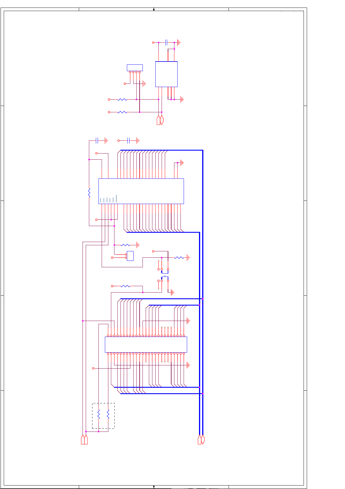
V33
0.1uF
C183
of
<Variant Name>
12 14Monday, October 25, 2004
1
123
4
JP006
HDR_4X1
V33
R164
2.00K
R163
V33 V33
0.1uF
C181
2.00K
0.1uF
C182
U021
SCL VCC
6 84123
SCL
5
SDA
SDA
7
WP
GND
NC0
NC1
NC2
24LC32A
Confidential
1
900-0254-00 Trinity Production Reference Design A
B
Debug Header, Flash, and EEPROM
Title
Size Document Number Rev
Date: Sheet
V33
2
R160 1.00K
V33V33
U020
VPP
37
13
VPP
VCC
OEWERPWPBYTE
CE
2628111214
D1D0D2D4D3D5D6D7D8
293031323334353638394041424344
D1D9D2
A0
25
47
A4
A5
A2
A1A8A3
D10D9D11
D10D3D11D4D12D5D13D6D14D7D15D8D16
A7A6A5A4A3A2A1
8
18192021222324
A7
A9
A6
A10
D12
A11
D13
D15
D14
46
27
45
GND1
GND2
Flash_8M
A18
A15
A14
A13
A12
A11
A10A9A8
A13
A12
A14
A15
A16
A17
A16
1234567
17
48
16
A18
A17
A19
2
FCEn
FWPn
R166
3
V33
V33
ICEn
4
12
JP004
10.0K
1
2
R165
10.0K
D10
D8
D4
D11
D9
34
56
78
910
11 12
13 14
15 16
D5
17 18
JP005
HDR_2X1
D7
19 20
V33
R167
10.0K
3214
SW3
5
6
SW_DPDT_SMT
A3
A12
A14
A16
A17
21 22
23 24
25 26
27 28
29 30
31 32
A7
A5D6A18
33 34
35 36
37 38
39 40
41 42
43 44
45 46
47 48
49 50
HDR_RA,25x2
3
4
Debugger Header
V33
A2
ICEWELn
A1
ICEWEHn
D12
D1
D3
D2
D0
D13
D14
D15
A15
A13
A11
A9 A10
A19
A6
A8
A4
DO NOT STUFF
R162 nc
R161 nc
5
D[15:0]
ROMOEn
ROMWEn
D D
C C
A[19:1]
B B
A A
5
Page 30

of
13 14Thursday, October 28, 2004
1
33343536373839404142434445464748495051525354555657585960616263
J005
12345678910111213141516171819202122232425262728293031
64
32
CON64
1
Confidential
900-0254-00 Trinity Production Reference Design A
B
Title
Size Document Number Rev
Date: Sheet
Video and SCART Connectors
YO13
CO13
R-OUT
L-OUT
YOUT
CVBSIN
AFT
MUTE
KEY1
KEY2
2
SSOG
3
C184
1nF
23SC
C205
12pF
2300Y
C185
0.1uF
23YLCR
C206
R189
47pF
40.2
2300C
C186
23CLCR23CR
0.1uF
C209
R192
40.2
47pF
R168 3.32K
L42
L40
560nH
C204
470pF
560nH
C208
470pF
23YR
34.8
CO13
R191
C207
R190
L41
270pF
75
23CCL
10nH
23YCL
R188
34.8
L39
C203
R187
10nH
270pF
75
4
YO13
5
D-L
D-R
L-OUT
YOUT
75
1K
R169
R175
R176
123
CONNECTOR COAX-J
456
J006
IR
CONTRAL
R-OUT
1K
RCA OUTPUT
SDA
LED-OUT
SCL
INT1
FID25
FID24
FID23
FID22
FID21
FID20
FID19
FID18
FID17
FID16
FID15
FID14
FID13
FID12
FID11
FID10
FID9
CVBSIN
2
1
1
FID42
1
1
1
1
1
1
1
1
1
1
1
1
1
1
1
1
FID41
FID40
FID39
FID38
FID37
FID36
FID35
FID34
FID33
FID32
FID31
FID30
FID29
FID28
FID27
FID26
1
1
1
3
FID57
1
1
FID56
1
1
FID55
1
1
FID54
1
1
FID53
1
1
FID52
1
1
FID51
1
1
DO NOT STUFF FOR EUROPE
4
FID50
1
1
FID49
1
1
FID48
1
1
FID47
1
1
FID46
1
1
FID45
1
1
FID44
1
FID43
1
5
D D
C C
B B
A A
Page 31

of
<Variant Name>
14 14Monday, October 25, 2004
1
1
Confidential
900-0254-00 Trinity Production Reference Design A
HDCR1
C187
0.18uF
2
HD1CRC
R170
C190
56pF
L031
470nH
C189
82pF
75
HDSOG1
C191
1nF
C192
HD1S
HD1YCHD1YF
R171 3.32K
L304
HDY1
0.18uF
470nH
C195
C194
R172
56pF
82pF
HDCB1
C196
0.18uF
B
Video Input Connectors
Title
Size Document Number Rev
Date: Sheet
2
HD1CBC
75
L037
C199
470nH
C198
R173
75
56pF
82pF
330nH
C193
L035
150pF
HD1YL
56nH
L036
HD1CRL
HD1CRF
3
L030
330nH
L032
56nH
L033
150pF
C188
2
2
2
VCCG VCCG VCCG
4
HD1CR
HD1Y
HD1CBL
HD1CBF
330nH
L038
56nH
C197
150pF
D022BAV99L
3
1
D021BAV99L
3
1
D020BAV99L
3
1
3
4
HD1CB
123
J007
456
CONNECTOR COAX-J
5
D D
C C
B B
A A
5
Page 32

YCD-R
D-L
R-OUT
L-OUT
CONTORL
MUTE
IR1
KEY1
AFT
1234596108
7
231468579
LEDIRKEY1
2314576
KEY2
181411172015131216192225272624302321282931
0
0
+12V
C-0805
C594 1uF
CPUMP
J505
33343536373839404142434445464847495051525354555657585960616263
1
+12V
+5V
J504
+5AV
J503
2
U505
+5VGEN
123456789
HEADPHONE_L
HEADPHONE_R
3
0
10u 25v
D-L
AV1-L
C636
4
100uF/10V
+5V
U511
R-OUT
Q503
+5V
Q502
R511
1K
3904
C524
1000p
0
C527
10u 25V
C528
10u 25V
0
AV3-L
C529
10u 25V
AV3-R
C530
10u 25V
C532
10u 25v
C533
10u 25v
AV1-R
C534
10u 25V
+5V
231
J508
BASS
L-OUT
4
+5V
D-R
C531
AV2-L
AV2-R
5
+9V
TV
KEY2
LED
MCSDA
MCSCL
Y-OUT
INT1
1
2
1
2
J507
J508
Y
+9V
10uH
L513
C602
22u 16v
32
64
P_ON
8MM10L
678
R2-
L2+
R2+
U509
R1+
R1-
L1+
L1- L2-
123
4 5
0.1uF
C-0805
C593
0.47uF
C-0805
C592
C590
L509 10uH
C586
R575
10
0.22uF
C-0805
0.22uF
C-0805
C584
C591
GND1
8MM10L
8MM10L
L510 10uH
L511 10uH
D512
D510
1N5817
D\4148S
GND1
0.1uF
C-0805
C595
0
32
NC
NC
VDDA
PGND1
D511
1N5817
D\4148S
C589
220u/25V
CE$8S
+
C588
0.1uF
C-0805
0
3136333435
VDD1
VDD1
OUTP1
OUTM2
OUTM1
0
R502
56
0.1uF
C601
C-0805
R586
680
Q511
2 3
BT3904
1
22K
15K
R585
R584
+
C600
100u 16v
0.1uF
C-0805
C587
0.47uF
C-0805
R576
10
0.22uF
C-0805
0.22uF
C-0805
FOR LOUNDSPEAKER
C585
GND2
1N5817
D\4148S
0
8MM10L
L512 10uH
D513
1N5817
D\4148S
GND2
GND1
C583
220u/25V
CE$8S
+
C582
0.1uF
C-0805
0 GND2
2021222324252627282930
NC
NC
VDD2
VDD2
DGND
OUTP2
PGND2
TA2024
DCAP2
DCAP1
V5D
AGND1
REF
OVERLOADB
AGND2
V5A
VP1
IN1
MUTENCVP2
IN2
BIASCAP
101112131415161718 19
20k
C575
C-0805
R565
8.2k, 1%
0
0
HEADPHONE_R
0
0.1uF
R636
C638
0
C637
100uF/10V
0
00
C633
5
100uF/10V
0
10K
R633
R1
Q504
3904
R517
1K
+9V
L504
10uH
D501
1N4148
0
C520 47u 25v
C519 47u 25v
C521
470p
0
32313029282726252321201918
CAPL-A
CAPL-M
AHVSUP
AHVSS
33
SC1-OUT-L
AGNDC
34
SC4_IN_L
35
SC4_IN_R
36
ASG
37
SC3-IN-L
38
SC3-IN-R
39
ASG
40
SC2-IN-L
41
SC2-IN-R
42
ASG
43
SC1-IN-L
44
SC1-IN-R
45
VREFTOP
46
MONO-IN
47
AVSS
48
AVSUP
ANA-IN+
ANA-IN-
ANA-IN2+
MSP34*5G
49505152535455565760616263
56P
C509 10n
C510 56P
C508
0
47U 25V
0.1uF
C-0805
R566
0
0
4.7
0
R518
1K
0
1K
R630
R516
24
22
NC
VREF1
SC2-OUT-L
DACM-SUB
SC1-OUT-R
SC2-OUT-R
IC204 DIP2 MSP34*5G
TESTEN
XTAL-IN
XTAL-OUTTPAUD-CL-OUT
NCNCNC
585964
X501
18.433M1
C512
C511
3.3P
0
0
L
1K
NC
3.3P
R567 10k
C576
R631
R
DACM-L
DACM-R
D-CTR-I/O1
D-CTR-I/O0
0
R506
2.2uF
1K
R515 1K
VREF2
ADR-SEL
10K
C-0805
17
DACA-L
DACA-R
STANDBYQ
+5V
R569
10k
C577
+
R568 1k
C630
1000p
C631
1000p
C518
1000p
C517
1000p
RESETQ
16
NC
15
NC
14
NC
13
I2S-DA-IN2
12
DVSS
11
DVSUP
10
ADR-CL
9
ADR-WS
8
ADR-DA
7
I2S-DA-IN1
6
I2S-DA-OUT
5
I2S-WS
4
I2S-CL
3
I2C-DA
2
I2C-CL
1
R507
C574
0.1uF
C573
0.1uF
C-0805
C572
0.1uF
C-0805
HEADPHONE_L
R635
4.7
0.1uF
C639
0.1uF
C635
C634
10uF/10V
2
314
TDA2822D
867
0
C632
10K
L1
R632
100uF/10V
R521
1K
+5V
3904
0
0
R520 1K
C522
47u 25v
C523 1n5
C525
100n PE
C526
3u3 25v
0
0
IC501
C507
100n PE
0
C506
10u 25v
10uH
L502
C505
C504
10n
0
D D
AGND3
20k
R571
10k
R570
C579
10uF
CE$4S
0
C-0805
2.2uF
C578
0 0
AUDIO L
AUDIO R
0
0
0
R510
10K
+5V
R509
1K
10U 25v
C516
C515
103
0
C514
47u 25v
C513
103
100
L503
10uH
R508
100
+5V
MCSDA
MCSCL
+9V
10uH
C605
L514
22u 16v
C-0805
C604
0.1uF
15K
R587
C603
C-0805
C625
0.22u
INPUT
U504
INPUT
123456789
0
C613
100P
C-0805
C500
0.22u
R577
75
V1
0
D507
1N4148
D1206
SLEEP FAULT
0.1uF
C-0805
0
+5V
L505
10uH/15m-ohm
3
Q506
NTD40N03R
SOT-23
1
MMSD4148T1
+12V
0
C C
0
Q512
BT3904
1
+
100u 16v
GROUND
DATA
0
C-0805
R579
MCSDA
0
+12A
4.7V
D506
0
470u 16v
C546
C545
470u 16v
C544
470u 16v
10uH/28m-ohm
R523
6.8K 1%
C540
D504
D503
R513
0
JP1
Y-OUT
R503
2 3
22K
R588
OUTPUT
INPUT
C596
0.22u
0
C612
100P
D\ZDS
3.6K 1%
123
104
2
47
4
C
10uH
L515
C608
22u 16v
0
R504
56
0.1u
C607
R592
680
Q513
2 3
BT3904
56
1
0
+
22K
15K
R591
R590
R589
680
C606
10u 16v
0
0
C553
C599
R582
120 OHM
47u/10V
+
R583
75
0
+9V
C1
0.22u
75
0
C598
+
47u/10V
0
C-0805
C597
0.1u
1206
+9V
121314151617181920
OUTPUT
OUTPUT
OUTPUT
OUTPUT
OUTPUT
GROUND
TEA6415C
CLOCK
INPUT
INPUT
PROG
INPUT
VCC
INPUT INPUT
10 11
C-0805
C-0805
0
C503
C-0805
C502
0.22u
R580
0.22u
C-0805
0
C-0805
C501
0.22u
R581
75
Y1
MCSCL
V3
L508
R578
75
0
V2
+12V
0
MUTE
R637
SOT-23
Q510
0
0
104
SOT-23
NTD40N03R
D502
C539
D508
1N4148
0
18V
104
C614 0.1U
POWER IN
DTC_0
R574
10K
1
DTC_0
SOT-23
BT1
2
1N4148
D1206
3
D509
Q509
2.2k
R573
C581
0.1uF
C-0805
2.2K
R572
D1206
Q508
BT3906
SOT-23
C580
220U/25V
CE$8S
+
0
+5AV
R525
R526
12K 1%
3K 1%
2K
R524
1K-1.5K
5VM
0
12
0
R598
12
R597
+5AV +5AV
SOT-23
3
C610
0.1uF
D514
BAT54C/BAV70
0
U508
S35380
10K
R615
ᅮᯊ䕀ৄ
D515
R617
1/1206
0
3.3V
D\ZDS
0
0
104
0
C542
R514
0
14
PGND
GATE_L
U502
GATE_H
BST
1234567 8
D\ZDS
0
C536
470u 16v
C535
470u 16v
0
+12A
123
J501
51K 1%
910111213
IS-
VC
IS+
VCC
CS5211
LGND
VFFB
VFB
COMP
SGND ROCS
C541
104
P_ON
R638
C543
Q507
MMSD4148T1
C615 100P
123
TV
R563
C-0805
0.1u
C618
0
+
C617
10u/16V
22K
R528
22K
R529
0
3904
Q501
1K
R512
BASS
AV3-R
AV3-L
+12V
10uH
C571
100uF/16V
L519
U506
7809
+9V
MCSDA
MCSCL
INT2
MCSCL
MCSDA
100
R599
R600 100
10K
10K
678
SCL
SDA
VDD
INT1
XOUT
XIN
VSS INT2
123
4 5
X502
32.768K
INT1
C616
C609
8pF
INT1
0
U503
+5AV
0
0
0
C570
1
I
G
2
O
3
C569
C568
ᅮᯊᓔ݇ᴎ
10K
R616
0
8pF
0
0
VSS
PC12F675
VCCIRCONTORL2
123
R519 100
L507
10uH
1206
3
O
L1117-5V
G
I
U507
1
L506
RELA1
C552
+
C551
10uH
0.1uF
100uF/16V
0.1uF
KEY1
KEY
R522 100
C611
C550
C549
2
C548
C547
LED
678
47u/10V
0.1u
0.1uF
OUT
INT1
2
4
82pF
C-0805
0.1uF
100uF/16V
100uF/16V
CONTORL
INT CONTORL1
4 5
D505
+12V
00
+9V
0
C565
+
10u/16V
C-0805
C564
0
0.1u
0
AV2-L
+5AV
R593220
Q519
R5940
3904
220
R596
220
R595
+5AV
0
INT2
0
Q520
3904
+5AV
0
R622
AV2-R
0
LED1
LED
LED0805
1
2
3
+9V
4
J506
5
0
R505
1K
Q521
3904
0
+5AV
000 0
IR
+9V
00
C558
+
10u/16V
C-0805
C557
R527
3904
Q505
1N4148
1
Jidian1
3
0.1u
C538
0
0
C537
470uF/25V
0.1u
1K
0
+9V
0
100K
R564
2
1K
C567
100u 16v
1K
R562
1K
R559
BASS
1
P508
47-RCA122-XX0
1
47-RCA013-XX2
2
R561
47K
0
Auido3
2
47K
R560
1
P507
47-RCA013-XX2
1
6FKHPHIRUDQDORJERDUG
V3
R558
1K
Q518
3904
0
AV3
R557
10K
R556
82
R555
22K
C566
100u 16v
R554
R551
0
2
1
P506
47-RCA013-XX2
1
47-RCA013-XX2
2
R553
47K
1K
1K
0
47K
2
R552
1
P505
47-RCA013-XX2
2
Auido2
0
R547
82
2
1
P503
47-SVI008-XX0
3
Auido1
0
3
AV2
0
P504
47-RCA013-XX2
4
0
0
5
V2
Q517
R550
1K
3904
R549
10K
0
C562
+
10u/16V
R548
22K
C561
0.1u
C-0805
C563
100u 16v
IR1
IR1
0
R619
1K
0
R618
5
VCC
U510
74LVC1G126
OEAGND Y
123 4
R621
10K
+5AV
R620
0
Y1C1
R546
1K
Q516
3904
0
82
R543
S-Video
0
R544
10K
22K
R545
C560
100u 16v
R540
22K
R541
10K
3904
1K
Q515
R539
R538
R535
4
5
C559
103
82
1
2
R542
0
0
1K
1
2
R537
47K
47-RCA013-XX2
1K
47K
2
R536
1
P502
47-RCA013-XX2
V1 AV1-R AV1-L
+9V
0
R501
220
5
4
AFT
3
2
1
J502
B B
+9V
C554
Q514
R533
1K
3904
0
AV1
R532
C555
+
10u/16V
C-0805
0.1u
10K
R534
82
R531
22K
C556
100u 16v
A A
0
2
1
P501
47-RCA013-XX2
Page 33

6 Explode View Diagram
 Loading...