

Page 1
Page 2
RISK
ELECTRI
SHOCK
NOT
OPEN.
SCHNEIDER ELECTRONICS GMBH-GERMANY
2
1. CAUTION
CAUTION:
Use of controls, adjustments or procedures other than those specified herein may result in
hazardous radiation exposure.
CA UTION: TO RE DU CE THE RIS K OF
CA U T IO N
RISK
OF ELECTR I
SHOCK
The lighting flash with arrowhead symbol, with an equilateral triangle is intended to
alert the user to the presence of uninsulated voltage within the products
enclosure that may be of sufficient magnitude to constitute a risk of electric shock to
the person.
The exclamation point within an equilateral triangle is intended to alert the user to the
presence of important operating and maintenance (servicing) instructions in the
literature accompanying the appliance.
DO NOT
C
OPEN.
ELECTR ICAL SHOCK , DO NOT RE MOVE
COVER (OR BACK). NO USER SERVICEABLE
PAR TS INS IDE . RE FE R SE R VIC ING TO
QUALIFIE D SERVIC E PERSONNEL.
dangerous
WARNING: TO REDUCE RISK OF FIRE OR ELECTRIC SHOCK, DO NOT
EXPOSE THIS APPLIANCE TO RAIN OR MOISTURE.
2
Page 3

SCHNEIDER ELECTRONICS GMBH-GERMANY
3
IMPORTANT SAFETY INSTRUCTIONS
CAUTION:
Read all of these instructions. Sa ve these instructions for later use . Follo w all W arnings and
Instructions marked on the audio equipment.
1. Read Instructions-All the safety and operatinginstructionsshouldbe read before the productis operated.
2. Retain Instructions- The safety and operating instructions should be retained for future reference.
3. Heed Warnings- All warnings on the product and in the operating instructions should be adhered to.
4. Follow Instructions- All operating and use instructions should be followed.
FOR YOUR PERSONAL SAFETY
1. When the power cord or plug is damaged or frayed, unplug this television set from the wall outlet and refer servicing to
qualified service personnel.
2. Do not overload wall outlets and extension cords as this can result in fire or electric shock.
3. Do not allow anything to rest on or roll over the power cord, and do not place the TV where power cord is subject to
traffic or abuse. This may result in a shock or fire hazard.
4. Do not attempt to service this television set yourself as opening or removing covers may expose you to dangerous
voltage or other hazards. Refer all servicing to qualified service personnel.
5. Never push objects of any kind into this television set through cabinet slots as they may touch dangerous voltage
points or short out parts that could result in a fire or electric shock. Never spill liquid of any kind on the television set.
6. If the television set has been dropped or the cabinet has been damaged, unplug this television set from the wall outlet
and refer servicing to qualified service personnel.
7. If liquid has been spilled into the television set, unplug this television set from the wall outlet and refer servicing to
qualified service personnel.
8. Do not subject your television set to impact of any kind. Be particularly careful not to damage the picture tube surface.
9. Unplug this television set from the wall outlet before cleaning. Do not use liquid cleaners or aerosol cleaners. Use a
damp cloth for cleaning.
10.1. Do not place this television set on an unstable cart, stand, or table. The television set may fall, causing serious injury
to a child or an adult, and serious damage to the appliance. Use only with a cart or stand recommended by the
manufacturer, or sold with the television set. Wall or shelf mounting should follow the manufacturer s instructions, and
should use a mounting kit approved by the manufacturer.
10.2. An appliance and cart combination should be moved with care. Quick stops, excessive force, and uneven surfaces
may cause the appliance and cart combination to overturn.
3
Page 4
SCHNEIDER ELECTRONICS GMBH-GERMANY
4
PROTECTION AND LOCATION OF YOUR SET
11. Do not use this television set near water ... for example, near a bathtub, washbowl, kitchen sink, or laundry tub, in a
wet basement, or near a swimming pool, etc.
Never expose the set to rain or water. If the set has been exposed to rain or water, unplug the set from the wall
outlet and refer servicing to qualified service personnel.
12. Choose a place where light (artificial or sunlight) does not shine directly on the screen.
13. Avoid dusty places, since piling up of dust inside TV chassis may cause failure of the set when high humidity persists.
14. The set has slots, or openings in the cabinet for ventilation purposes, to provide reliable operation of the receiver, to
protect it from overheating. These openings must not be blocked or covered.
Never cover the slots or openings with cloth or other material.
Never block the bottom ventilation slots of the set by placing it on a bed, sofa, rug, etc.
Never place the set near or over a radiator or heat register.
Never place the set in enclosure, unless proper ventilation is provided.
a built-in
PROTECTION AND LOCATION OF YOUR SET
15.1. If an outside antenna is connected to the television set, be sure the antenna system is grounded so as to provide some
protection against voltage surges and built up static charges, Section 810 of the National Electrical Code, NFPA No.
70-1975, provides information with respect to proper grounding of the mast and supporting structure, grounding of the
lead-in wire to an antenna discharge unit, size of grounding conductors, location of antenna discharge unit, connection
to grounding electrode, and requirements for the grounding electrode.
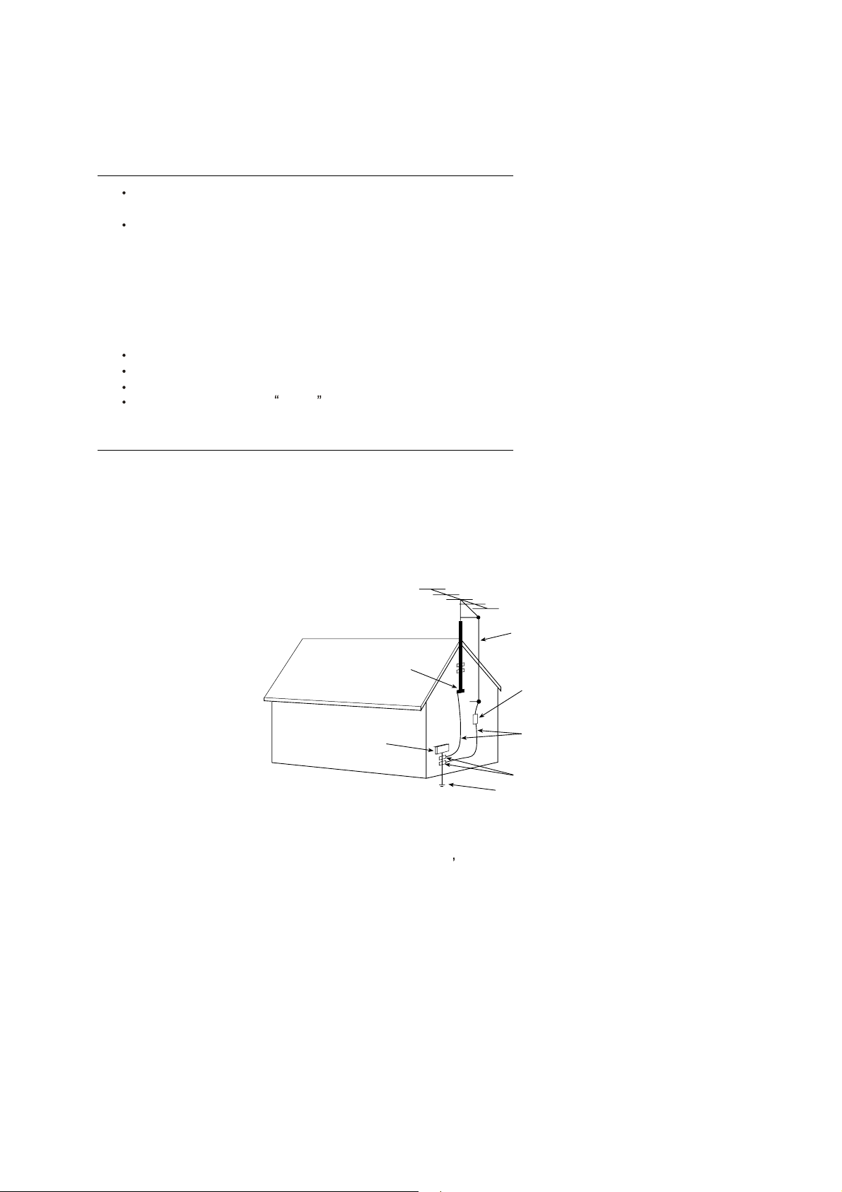
EXAMPLE OF ANTENNA GROUNDING AS PER NATIONAL ELECTRICAL CODE INSTRUCTIONS
EXAMPLE OF ANTENNA GROUNDING AS PER
NATIONAL ELECTRICALCODE
ANTENNA
LEAD- IN WIRE
GROUND CLAMP
ELECTRIC SERVICE
EQUIPMENT
NEC-NATIONAL ELECTRICALCODE
ANTENNA DISCHARGE
UNIT (NEC SECTION
810-20)
GROUNDING
CONDUCTORS
(NECSECTION 810-21)
GROUND CLAMPS
POWER SER VICE GROUNDING
ELECTRODE SYSTEM
(NEC ART 250. PART H)
15.2. Note to CATV system installer : (Only for the television set with CATV reception)
This reminder is provided to call the CATV system attention to Article 820-40 of the NEC that provides
installer s
guidelines for proper grounding and, in particular, specifies that the cable ground shall be connected to the grounding
system of the building, as close to the point of cable entry as practical.
16. An outside antenna system should not be located in the vicinity of overhead power lines or other electric lights or power
circuits, or where it can fall into such power lines or circuits. When installing an outside antenna system, extreme care
should be taken to keep from touching such power lines or circuits as contact with them might be fatal.
17. For added protection for this television set during a lightning storm, or when it is left unattended and unused for long
periods of time, unplug it from the wall outlet and disconnect the antenna. This will prevent damage due to lightning
and power-line surges.
4
Page 5

SCHNEIDER ELECTRONICS GMBH-GERMANY
5
OPERATION OF YOUR SET
18.
This television set should be operated only from the type of power source indicated on the marking label.If you are not
sure of the type of power supply at your home, consult your television dealer or local power company. For television
sets designed to operate from battery power, refer to the operating instructions.
19. If the television set does not operate normally by following the operating instructions, unplug this television set from the
wall outlet and refer servicing to qualifiedservice personnel. Adjust only those controls that are covered in the operating
instructions as improper adjustment of other controls may result in damage and will often require extensive work by a
qualified technician to restore the television set to normal operation.
20. When going on a holiday : If your television set is to remain unused for a period of time, for instance, when you go on
a holiday, turn the television set and unplug the television set from the wall outlet.
off
IF THE SET DOES NOT OPERATE PROPERLY
21. If youare unable to restorenormal operationby followingthe detailedprocedurein your operating instructions,
do not attempt any further adjustment. Unplug the set and call your dealer or service technician.
22. Whenever the television set is damaged or fails, or a distinct change in performance indicates a need for
service, unplug the set and have it checked by a professional service technician.
23. It is normal for some TV sets to make occasional snapping or popping sounds, particularly when being
turned on or off. If the snapping or popping is continuous or frequent, unplug the set and consult your
dealer or service technician.
FOR SERVICE AND MODIFICATION
24. Do not use attachments not recommendedby the television set manufacturer as they may cause hazards.
25. When replacementparts are required,be sure the service technician has used replacementparts specified
by the manufacturer that have the same characteristics as the original part. Unauthorized substitutions
may result in fire, electric shock, or other hazards.
26. Upon completion of any service or repairs to the television set, ask the ser vice technician to perform
routine safety checks to determine that the television is in safe operating condition.
5
Page 6
EM BUSINESS CENTER
r
:
A
FTV PRODUCT MANAGEMENT DEPT.
SPECIFICATION RELEASE
Version: V1.0 Issued Date: 2008.06.03
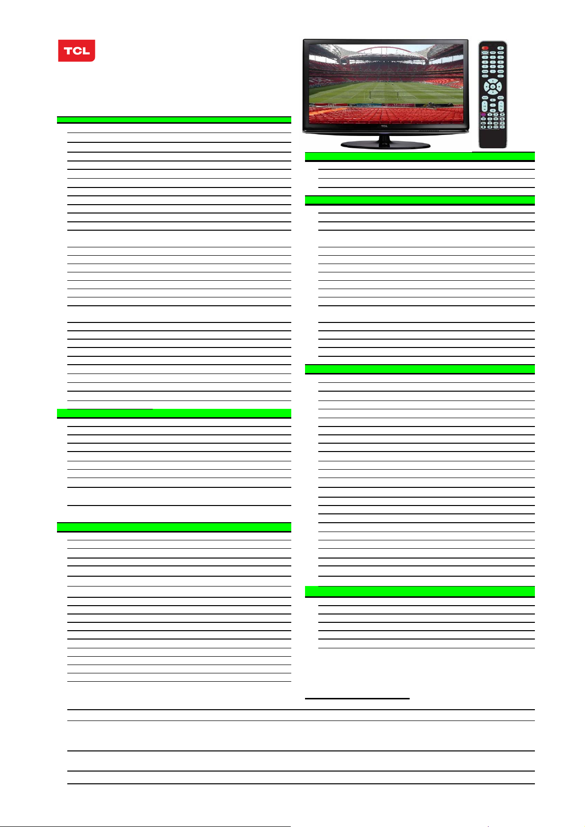
Model: L32E9A/MS91-AP
PICTURE
Panel Size (inch) 32"
Category
Aspect Ratio 16:9
Color Temperature Cool/ Normal / Warm SIGNAL FORMAT CAPABILITY
Backlight Adjustable Yes Component Video Format Y,Pb/Cb,Pr/Cr:up to 1080P(see note 3)
Scaler Mode 4:3、14:9、16:9 、FULL DVI Video Format -Picture Effect 4 picture effects preset (Standard 、Bright、Soft、User) HDMI Video Format Up to 1080P(see note3)
Film Mode (3:2 pull down) Yes PC Compatibility see note 3
Picture Enhancement TERMINALS
Comb Filter 3D
Core Technology
CCS -- Audio Input for S-Video Share with Audio for AV2
TM
DCDi
Blue Stretch Yes Audio Input for YPbPr
Black Stretch Yes YCbCr Input
Motion Compensation Yes Audio Input for YCbCr
DLTI Yes VGA Input(RGB)
DCTI Yes Audio Input for RGB
Dynamic Skin Correction Yes DVI
DNR Yes Audio Input for DVI
Other Feature
Panel Specification
Panel supplier SAMSUNG
Viewing Technology PVA Headphone Output
Display Resolution 1366×768 RF Input(Antenna)
Brightness (cd/m2) 450 USB
Contrast Ratio 2000:1 BASIC INFO.
Response Time
Viewing Angle (H/V)
Life Time 60,000hrs Channels
Color
SOUND Certification
Speakers Integrated speakers (Bottom side) Power Supply
Audio Power Output 5W*2+8W(Woofer) Power Consumption-TV on
Sound Processing NICAM B/G ,D/K,I,Stereo;A2
DVSS (Dolby Virtual Surround) -- Default Color of Front Cabinet
DDAS (Digital Dynimic Audio System)
AVC (Auto Volume Control)
BBE
SRS
Sound Features
Sound Control
FUNCTION Base Stand
V-Chip -- Net Weight (Kg)
CCD (Closed Caption) -- Gross Weight (Kg)
Teletext -- Container Loading
PIP/POP Yes see note 1 20 feet
Macro Vision TBD 40 feet
Calendar -- 40 feet high
Clock/Timers Yes ACCESSORIES
Lock Yes(Child Lock to lock keys)
OSD Language English/French/Farsi/Russian/Arabic Remote Control For TV control (with two 7# batteries)
OSD Features -- Base Stand
Card Reader -- Speaker Box
DVD Combo -- Wall Mount
USB Connection Yes. Support Mp3、JPEG see note 2 Others AC Power Cord
Game --
Screen Saver --
Demo Function --
Picture Freeze Yes
LCDTV
High-quality scaling engine&3-D video de-interlace
Edge-oriented adaptive algorithm for smooth low-angle
edges YPbPr Input
DBC(Dynamic Backlight Control)
DCC(Dynamic Contrast Control) HDMI
8ms (G to G)
178°/178°
16.7M
Yes
Yes
No
Yes
AV Stereo、AVC、NICAM、 Equalizer
Volume、 Balance、 5 Sound Mode (Standard ,
Movie,News,Music,User)
Audio/CVBS Input (Composite)
S-Video Input 1
Audio/CVBS Output (Composite) 1 (R/L+CVBS) (RCA)
SPDIF Output
TV System PAL B/G、/K、I ;SECAM B/G、D/K
AV System
Chassis
Power Consumption-Standby
Keyboard Position
Base Stand Detachable
Unpackaged Dimension for Main Body (L*H*D) (mm)
With Base Stand (mm)
Without Base Stand (mm)
Packaged Dimension (L*H*D)
Main Body (mm)
Speaker Box
Operation Manual English(Default)
Drafted by: 张勇 2008-06-03
3 R/L+3 Video: AV1、AV2 、AV3(side)
1
1
Share with "YPbPr"
Share with Audio for "YPbPr"
1 (D-Sub,15 Pins)
Share with Audio for "YPbPr"
--
--
2
1 (Optical sound out,RCA)
1 (Φ3.5mm )
1 (IEC Type)
1 Standard
PAL、NTSC
199(1~199)
MS91-AP
CB
AC 100V-240V 50/60Hz
130W
<3W
Black
Touch keyboard on the left side
Yes
796*584*231
796*534*104
915*652*260
--
Packaged with Main Body
13.3
16
188
396
440
Integrated Packaging
Integrated
Optional
pproved by:
Design and specifications are subject to change without notice! Page 1 of 1
Note:
In PIP/POP mode,all the sources are divided into two groups. Group 1 includes TV,AV1~AV3,S-Video,Group 2 includes Y,Pb,Pr,VGA,HDMI1~HDMI2. If the
Main window display one of the source in Group 1, the Sub window can only display one of the source in Group 2, vice versa. The source in different group
1. PiP POP
2. USB
3. HDMI,VGA,YPbPr format
displayed at the same time can not be supported.
The standard USB port can only be used for picture display and audio play.The file in JPEG and MP3 format can be supported.
Detail information refer to relevant file
Page 7

TCL Multimedia Technology Holdings Ltd.
R&D Center
Alignment Procedure
:
MODEL
Version 1.0
PREPARED BY : Wise Zhang DATE : 2008-5-7
L42E77F/MS91AP LCDTV
APPROVED BY: DATE:
Page 8

O
verview:
L
CDTV features by its small size, low weight, perfect display effects as well
as energy saving and low radiation. It can not only be used to receive TV program,
but also as PC monitor.
Note:
Factory Menu(FM) is designed for factory. R&D Menu (RDM) is for R&D purpose and
should not be changed in the process of production.
H
ow to access to Factory Menu?
1. Firstly, in TV mode, press MUTE button of remote control to mute the set.
Secondly, press MENU button to enter user main menu. Then choose CONTRAST item in
PICTURE menu and press 9,7,3,5 buttons in series. Factory Menu will appear in the
left top of screen.
2. Press RETURN button when FACHOTKEY is enabled (ON).
Note: After upgrading the software for the first time. Restart the set (power off
then power on) should be made to ensure the correct EEPROM data.
F
M(Factory Menu) menu
Item Default Description Status
FAC HOTKEY OFF Shortcut button to enter Factory Menu.(OFF:disable;ON:
enable),After production, the item must be disabled.
WARM UP OFF OFF:normal mode,the set will turn to standby mode
when no signal inputted
ON:Aging mode,the set will display blue screen
when no signal inputted. Usually the value should
be set to off when aging test.
ADC Calibration of ADC data OK
WHITE
BALANCE
White balance data adjustment OK
OK
OK
SHOP DO Reset the set after production to remove all unnecessary
factory debug information and the Factory Menu will can
not access for users.
NVM RESET DO Restore the system to default value. This operation
will remove the white balance data. This function
only designed for R&D.
OK
OK
Page 9
SET FAC CH DO Preset the channel list of factory to provide convenience
for production.
OK
Power on LAST STB: The set will turn to standby mode when switch on.
LAST:remember the status of last switch off.
ON: power on when switch on.
PVR UPGRADE DO OK
VERSION Display the version of software. OK
PVR VERSION OK
OK
ADC calibration:
Item Default Description Status
SOURCE Current source OK
R OFFSET 127 R offset, manually adjustable. Should not be changed
after automatic adjustment.
G OFFSET 127 G offset, manually adjustable. Should not be changed
after automatic adjustment.
OK
OK
B OFFSET 127 B offset, manually adjustable. Should not be changed
after automatic adjustment.
R GAIN 127 R gain, manually adjustable. Should not be changed after
automatic adjustment.
G GAIN 127 G gain, manually adjustable. Should not be changed after
automatic adjustment.
B GAIN 127 B gain, manually adjustable. Should not be changed after
automatic adjustment.
AUTO TUNE Before calibration, first, please input
corresponding pattern according to the
instruction at the bottom of the menu. Second,
select AUTO TUNE, Then press vol- button in remote
control to calibrate ADC automatically. The result will
be displayed.
OK
OK
OK
OK
OK
WHITE BALANCE adjustment:
Item Default Description Status
SOURCE AV1 current source. Only AV1, HDTV, VGA need be
adjusted.
OK
Page 10
COLOR TEMP NORMAL NORMAL/COOL/WARM OK
R GAIN 129 R offset, manually adjustable. Should not be changed
after automatic adjustment.
G GAIN 128 G offset, manually adjustable. Should not be changed
after automatic adjustment.
B GAIN 126 B offset, manually adjustable. Should not be changed
after automatic adjustment.
R OFFSET 126 R gain, manually adjustable. Should not be changed
after automatic adjustment.
G OFFSET 126 G gain, manually adjustable. Should not be changed
after automatic adjustment.
B OFFSET 128 B gain, manually adjustable. Should not be changed
after automatic adjustment.
H
ow to access to R&D Menu?
1. Firstly, in TV mode, press MUTE button of remote control to mute the set.
OK
OK
OK
OK
OK
OK
Secondly, press MENU button to enter user main menu. Then choose CONTRAST item in
PICTURE menu and press 1,9,5,0 buttons in series. R&D Menu will appear in the left
top of screen.
2. Press RETURN button when Design Menu->DESIGNKEY is enabled (ON).
3. Press MENU button of remote control under FM.
R&D Menu(RDM)
Item Default Description Status
DESING KEY OFF Shortcut key control switch of Design Menu
(ON: enable, OFF: disable)
FAC MENU To enter Factory Menu OK
SHOP INIT Should not be adjusted by factory. OK
OK
OTHERE Other settings. NG
SERVICER
MENU
Product information NG
Page 11
PARAM
SETTING
HOTEL MENU Hotel menu NG
Parameter settings OK
SHOP INIT Function
Item Default Description Status
VOLUME 30 Volume default value(0~100) OK
PIC MODE STANDARD Picture mode(Soft, Standard, Bright, User) OK
SOUND MODE STEREO Sound Effect(Stereo,Movie,News,Music Hall,Personal) OK
CH NUMBER 199 Channel number(0-199) OK
LANGUAGE ENGLISH Language(English/French/Farsi/Russian) OK
COLOR SYS AUTO TV Color system(AUTO, PAL, SECAM) OK
SOUND SYS D/K Sound system(D/K,B/G,I) OK
PRESET CH 1 Channel preset(0-199) OK
COLOR TEMP NORMAL Color temperature(NORMAL,WARM,COOL) OK
PARAM SETTING
Item Default Description Status
VOLUME Sound curve adjustment OK
BRIGHTNESS Luminance curve adjustment OK
CONTRAST Contrast curve adjustment OK
SATURATION Saturation curve adjustment OK
SHARPNESS Sharpness curve adjustment OK
DEBUG BOARD:
During production the Debug Board will be used to upgrading software, adjust White
Balance. The function of the board is transfer TTL Voltage to 232 Voltage. 12V DC
power supply should be provided through CON1/CON2.
Page 12

T
he steps of debug during production:
Manually adjustment of White Balance and ADC calibration:
1) ADC calibration
Input dual 16 grey scale signal 1024*768/60Hz(Chroma2225 Pattern47,Timing38 or
Chroma2327 Pattern47, Timing14) from VGA socket
Input 8 color bar with 100% saturation(2327 Pattern37, Timing33 or BSG360A Timing79,
Pattern85), PAL system from Y,Pb,Pr socket.
Enter ADC item of Factory Menu, select the source which you are going to calibrate.
Then select AUTO TUNE and press Vol- button in remote control.
Note: First confirm the input signal pattern and format are correct. After
calibration, If the grey scale can not be distinguished, calibrate again until it
is distinguished.
Color Temperature adjustment.
Before adjustment you should confirm the color analyzer has been calibrated. During
the process, only AV1 Y,Pb,Pr,VGA source should be adjusted. We recommend you use
CA210 color analyzer(0 channel),because it is more accurate.
Connection of devices:
1) connect CON3 of Debug Board to CA210(input VGA signal to CON6 when adjust VGA
source. Connect CON5 of Debug Board to the set through VGA cable. Input
corresponding pattern required, then select GAIN AUTO,press Vol+ button of
remote control.
2) Input 8 grey scale signal of 5418 from AV1/Y,Pb,Pr/VGA source. Point the optical
lens to the fourth brightest scale. Then enter Factory Menu and select WHITE
BALANCE page, select GAIN AUTO, press Vol+ button of remote control.
Note: In the process of adjustment, you can press MUTE button of remote control
to cancel.
Page 13
Z602
SAWF (Picture)
Z600
AP market use:
07-380FI5-NA7G
AP market use:
07-457FF5-NA1G
AP: 45-SAWK62-74D
LA: 45-SAWF39-530
Z601
SAWF (Sound)
AP: 45-SAWK93-52M
LA: 45-SAWF93-700
TUNER I2 C
DDC1
DDC1
U503(NC)
EDID
24C02
U507
Q501
13-0PS321-
P500
P501
DDC2
TMDS1
TMDS2
DDC2
`
U509(NC)
EDID
24C02
U305
HDCP KEY
24C02
00B
PS321 is
integrates
3-to-1
HDMI/DVI
switch
I2 C
STA333BW Power on sequence
DC Power On Sequencie MST6*19GL Power On Sequence
CH1—12V
CH2— 5VSTB
CH3— HWRESET
CH4— +5V
LC
Low Pass Filter
LC
Low Pass Filter
OUT1A
OUT1B
OUT2A
OUT2B
CH1—5VSTB
CH2— HWRESET
CH3— VCC_1.26V
13-STA333-BWB
2.1 channels high
efficiency digital
U600
AP market: 13-TDA988-TSB
TDA9886,support PAL,SECAM and
NTSC
LA market: 13-TDA988-5TBS
TDA9885,support PALand NTSC
I2C-bus controlled single and
multistandardalignment-free IF-PLL
demodulators
P300
ISP
P1
U700
`
U400
VGA DDC
24C02
ISP SW
Q400
Q401
Q402
HDMI HPD CONTROL
HDMI DDC I2C
HDMI TMDS
PLL
47-EAR005-XX0
Or 47-EAR002-XX0
PORT
VGA PORT
STA333BW
audio system
Q601
For AP market
SIF 4M5 Trap
Q605
For LA market
SIF
MONO--SET NC FOR EM
P200
P200
Side AV
Board P5
P202
P203
P204
Y/C Audio share with L1/R1
AV1 L1/R1
AV2 L2/R2
AV3 L3/R3
YPBPR L4/R4(Share with VGA)
UART (RXD TXD)
R G B HS VS
U305(NC)
EEPROM
24C64
U301
EEPROM
24C64
I2 S
RESET
U702
13-TDA130-8TB
47-USB002-XX0
PH-L/PH-R
IR
KEY
U303
13-EN25B1-6TB (EN25B16)
16Mbit serial flash memory
TV-V
USB D+/D-
45-OSC14M-3Y2
X300
14M3
HWRESET
AP market use:
13-MST6E1-9GBS1
Ordering: MST6E19GL-
LF-S1
LA market use:
13-MST6M1-9GBS1
Ordering: MST6M19GL-
LF-S1
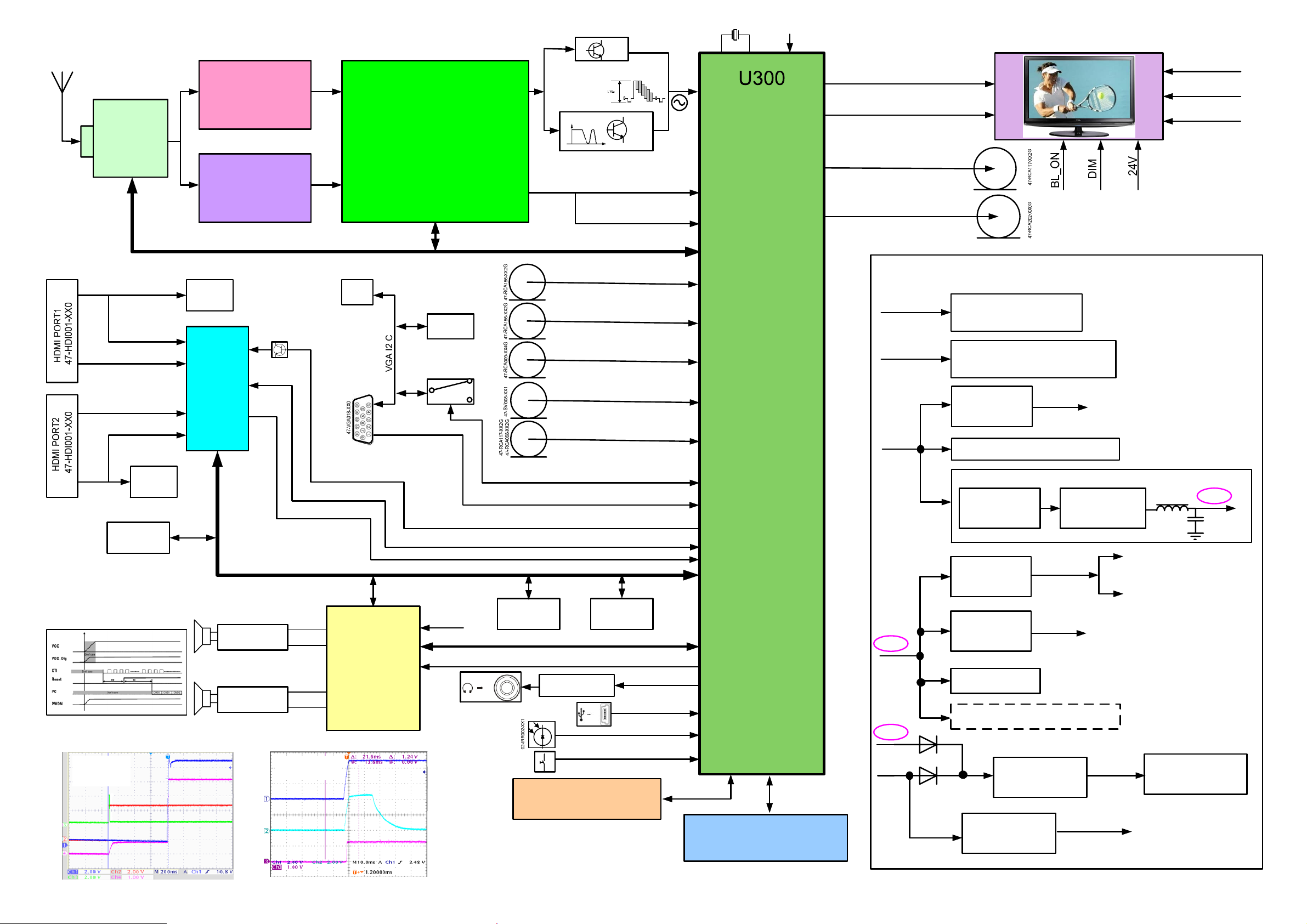
The MST6*19GL is a
high performance and
fully integrated IC for
multi-function LCD
monitor/TV with
resolutions up to full HD
(1920x1080). It is
configured with an
integrated triple-ADC/
PLL, an integrated DVI/
HDCP/HDMI receiver, a
multi-standard TV video
and audio decoder, two
video de-interlacers, two
scaling engines, the
MStarACE-3 color
engine, an on-screen
display controller, an 8-
bit MCU and a built-in
output panel interface.
By use of external frame
buffer, PIP is provided
for multimedia
applications.
Furthermore, 3-D video
decoding and processing
are fulfilled for high-
quality TV applications.
To further reduce system
costs, the MST6*19GL
also integrates intelligent
power management
control capability for
green-mode
requirements and
spread-spectrum support
for EMI management.
U301
13-281622-FTB4
HY5DU281622FTP-4
DDR,8Mx16, Max clock is 250MHz
Odd Pixel LVDS Signal
Even Pixel LVDS Signal
TV CVBS、 L/R Output
SPDIF
24V
12V(or 18V)
13-LD1117-50B
12V
For LCD Panel TCON,Use F801
13-LD1117-33B
+5V
13-LD1117-25B
For USB Module
+5V
5VSTB
D806
D805
LCD Panel
P203
P210
Power Supply Block Diagram
For Panel Inverter Board
For U700, Audio Power Supply
U601
LD0
U805
13-RT8110-00B
RT8110
U801
LD0
U802
LDO
For LCD Panel TCON,Use F800
13-IC1084-CMB
U803
DC/DC
13-MP1411-DHB
5V-IF
+3.3AVDD
2.6VM
U800
LD0
For Tuner,U600
DC/DC
U804
12-13N03L-0BX
PHKD13N03LT
AVC33,For U507
For I/O
For DDR
3.3VSTB
VCC_1.26V
For U300,Such as
AVDD_AU,AVDD_3
For U300 VDDC
12V or 5V
LVDS_SEL
RPF(CMO)
L800
+5V
C886
3,VDDP,PLL etc.
MS91-EM Chassis Block Diagram
First Issued V1.0
ZCX 2008-07-07
Page 14

L42E77F(MS91-AP)
版本:V1.0
制作日期:2008-4-17
原理图
制作:张睿 批准:
Page 15
AMP_+12V
loudspeaker circuit
NC
R742
0R
R741
0R
C716
AMP_+12V
25V
C700
25V
OUT2B
C746
C701
OUT2A
1U
220U
C717
OUT1B
0.1U
C745
220U
OUT1A
1U
C718
C715
0.1U
0.1U
R744
0R
AGND
U700
1
2
3
0.1U
4
5
6
7
8
9
10
11
12
13
14
15
16
17
18
NC
R743
0R
GND_SUB
SA
TESTMODE
VSS
VCC_REG
OUT2B
GND2
VCC2
OUT2A
OUT1B
VCC1
GND1
OUT1A
GND_REG
VDD
CONFIG
OUT3B
OUT3A
3V3
STA333BW
3V3
VDD_DIG2
GND_DIG
INT_LINE
RESET
LRCKL
BICKL
PLLGND
PLL_FILTER
PLL_VDD
POWERDN
VSS_DIG
VDD_DIG
OUT4B
OUT4A
SCL
SDA
SDI
XT1
headphone circuit
C729
L49
2U2
220R
PH-L
PH-L
AGND
C726
L50
2U2
220R
PH-R
PH-R
10K
AGND
3V3
L710
R704
36
35
I2C_SCL
34
I2C_SDA
33
32
31
30
29
28
27
26
25
24
23
22
21
20
19
AGND
10K
C730
0.1U
R711
C727
0.1U
3V3
600R
3R3
L711
600R
I2C_SCL
I2C_SDA
Single point to DGND
RESET#
R700
33R
R702
33R
L713
120R
PWDN
R703
3R3
100U
16V
R715
C710
33K
R718
10K
C728
100P
C720
0.1U
AGND
33R
C719
0.1U
R717
R707
10K
LL4148
D700
C721
1000P
25V
4U7
C744
R701
R705
33R
PLLGND
PLL_FILT
3V3
Single point to DGND
R714
33K
6
7
8
TDA1308T
R749
0R
As close as possible to the pin
3V3
AGND
C731
0.1U
R720
10K
C732
100P
45
3
2
1
U701
RESET
0.1U
C755
5V-IF
AGND
R739
100R
16V
AGND
4700P
R706
2K2
C723
120R
L712
AGND
C713
100U
AOSDATA
AOLRCLK
AOBCLK
AOMCLK
C722
680P
Single point to GND
C712
47U
C711
16V
47U
16V
R730
L701
OUT1A
R746
0R
AGND
AOSDATA
AOLRCLK
AOBCLK
AOMCLK
R1050
1R
2W
R1051
1R
AMP_12V
PH-LIN
PH-RIN
R709
R719
10K
10K
AGND
OUT1B
OUT2A
OUT2B
AMP_+12V
2W
C743
0.1U
AGND
AGND
C724
NC
2200P
R710
2K2
R708
2K2
C725
NC
2200P
AGND
2U2
C1010
C
Q980
C144ET
E
AGND
22UH
C734
330P C702
R725
22R
R747
22R
330P
C754
L700
C733
330P
R723
22R
PHONE_L
PHONE_R
2U2
C1011
Q981
B
C144ET
C739
0.1U
R728
6R8
R727
6R8
AGND
C741
L702
0.1U
22UH
22UH
C736
0.1U
R726
6R8
R724
6R8
AGND
C742
L703
0.1U
22UH
HP_DET
PHONE_L
PHONE_R
C
B
E
AMUTE1
0.22U
0.22U
0.22U
0.22U
0.47U
C740
C735
C753
0.47U
C737
C703
C738
0.47U
HP_DET
PHONE_L
PHONE_R
AGND
0R
R750 0R
R748
1000P
C748 C747
1000P/100N
PHONE_L
PHONE_R
1000P
1000P
AGND
C750
C752 C751
1000P
AGND
1000P/470N
C749
5V-IF
1
2
3
R721 0R
R745
4
5
6
R722
0R
7
P700
HP_AMUTE
NC
0R
3K3
R729
3K3
AMP_+12V
AGND
R731
3K3
R732
3K3
AMP_+12V
C708
470U
AMP_+12V
25V
25V
AGND
25V
C707
470U
25V
C705
470U
AGND
C706
470U
AGND
12V_IN
D702
LL4148
SPR+
1
R962
2
10K
SPR-
3
4
5
6
SPL-
P702
3V3
3V3
R735
330
BT3906
E
SPL+
B
Q915
30R
C4
25V
C
47U
R960
L705
AMP-MUTE
AGND
10K
+3.3VSTB
R734
2K
BT3906
B
R963
1K
C709
25V
47U
3V3
AGND
R738
4K7
R733
4K7
AMUTE1
E
HP_AMUTE
C
Q701
R736
10K
D701
LL4148
3V3
3V3
R737
10K
C
B
E
BT3904
R740
100K
AGND
PWDN
Q700
C704
10U
Page 16
12V_IN
4
4
U601
R600
15R
2W
16V
LD1117S50
C639
10U
0.1U
C648
123
16V
10U
5V-IF
C647
C646
0.1U
AGND
Pre IF amplify
Z600
AGND
D603
16V
4.7U
0.1U
C601
C621
1
AGC
2
AS
3
SCL
4
SDA
5
NC
6
BP
7
BT
8
IF1
AGND
R634
22K
33V
LL4148
12K
R628
TAGC
R626
100R
TUNER_SCL
TUNER_SDAR627 100R
100P
C636
100P
C637
AGND
10U
C638
0.1U
C635
5V-IF
L610
600R
AGND
12V_IN
R602
100R
C651
16V
10U
AGND
0.01U
1UH
L602
C652
0.01U
39R
R603
4K7
56R
R605
C653
R604
1K
0.01U
R606
1K2
C654
R608
0.82UH
680R
L603
C
Q604
B
SC3779
E
R607
56R
R609
0.01U
C624
AGND
R625
NC
R638
AGND
R610NCR611
R648
0R
L611
1UH
51R
R669
0.01U
C623
0R
312 45
5V-IF
AGND
NC
R629
R630
0R
R631
0R
NC
1UH
R632
L613
0R
NC
SIFM
SIFP
312 45
SAW-K9352M
Z603
Z604
SAW-K6274D
R633
312 45
AGND
BA982
D602
6K8
R656
2K2
C144ET
5V-IF
10K
R657
10K
R658
C
Q603
B
E
0R
NC
1UH
R637
L612
0R
NC
VIFP
VIFM
SIF_SW
AGND
AGND
5V-IF
R672
L606
2.2K
1000U
C626
4.7U
16V
0.1U
C650
AGND
oscillate frequency is about 440Khz
1000U
L607
C611
200P
0.1U
C612
132
D604
0BAV99
AGND
0.1U
C613
R635
100K
270P
C610
C
Q600
B
BC846B
L605
1000UR
4700P
C609
D600
0.01U
C614
2K2
R612
AGND
33V
33V
E
AGND
R636
47K
AGND
AGND
R1013
BA982
D601
6K8
SAW-K9352M
Z601
Z602
SAW-K6274D
312 45
AGND
10K
R613
C
Q602
C144ET
E
R645
R644
22K
22K
AGND
SIFPOUT
NC
TDA9885T
R643
0.1U
22K
C620
R661
100R
R662
100R
C625
0.1U
R663
1K
NC
C627
R664
0.1U
100R
NC
SIF_SW
R641
1.5NF
C617
R639
NC
232422
SIF1
VIF2
220NF
C616
21
VP
AFC
OP2
VPLL
OP1
FMPLL
DEEM
AFD
470NFC640
0.01UFC641
AGND
5V-IF
0.01UF
R667
5K6
SIF2
U600
VIF1
1234567
C643
390PF
C642
10K
R614
B
AGND
470NF
330R
C619
C618
16
181920
REF
VAGC
AGND
DGND
AUD CVBS
TOP
SDA
817
9
101112
1NF
C649
X600
4M
22PF
131415
NC
TAGC
SCL
SIOMAD
2K
R666
R670
0R
TAGC
R640
100K
AGND
5V-IF
L601
600R
C602
16V
47U
0.1U
C
Q601
C622
B
BT3904
E
TUNER_SCL
TUNER_SDA
SIFP
AGND
R649
75R
R647
220R
TV1-V
TV1-V
R622
0R
330P
C605
C606
R619
47R
75R
R621
330P
R620
47R
TV1-VIN+
TV1-VIN-
AGND
AGND
SIFM
R623
10K
R624
12K
560P
C604
TV1-L/RIN
AGND
Page 17
AV1-R
DVD/R
AV1-L
DVD/L
P203
9
RED
8
RED
R207
AV1-V
R241
0R
R242
0R
0R
NC
D5V0S2
D2
R243
R244
AV2-V
AV2-L
D5V0S2
D4
AV2-R
0R
D1
D5V0S1
1
3
2
D5V0S1
1
3
2
330P
C222
R208
10K
AGND
560P
C223
R211
AGND
10K
C224
R267
0R
330P
D3
C237
R271
AGND
10K
C239
R272
10K
C238
S-VIDEO
6
2
P202
5
7
1
3
4
75R
NC
R209
12K
R210
560P
12K
AGND
R265
NC
75R
R270
560P
12K
AGND
R269
560P
AGND
2
3
1
0.5Vp-p when input
R204
47R
AV1-VIN+
R206
AV1-LIN
AV1-RIN
R266
47R
R268
47R
AV2-LIN
12K
R234
0R
330P
C234
AGND
D5
D5V0S2
C235
330P
0R
R237
Note:when SCR+,SCG+,SCB+ as scart RGB
input,R339(net SC_SOG,from AV input)must
be 470ohm,R305must be NC,else SCR+,SCG+,
SCB+ as HDTV input, R305(net SC_SOG,from
HDTV input)must be 470ohm,R339 must be NC.
AV1-LIN
AV1-RIN
AV2-VIN+
AV2-LIN
AV2-RIN
AV2-RIN
R233
47R
R232
NC
75R
75R
R235
NC
47R
R236
AV2 AND AV1 CIRCUIT
AV1-VIN+
P200
9
RED
8
RED
AV2-VIN+
AV2-VIN-AV2-VIN-
WHITE
YELLOW
YELLOW
SV1-YIN
SV1-CIN
7
6
WHITE
5
4
3
2
1
SV1-YIN
CVBSOUT level is
0.5Vp-p when input
signal is 1Vp-p, so
SV1-CIN
BACKUP FOR P200 and TCL#ON is 47-RCA248-XX1G
AGND
AV1-R
AV2-R
AV1-L
AV2-L
AV1-V
AV2-V
AGND
1
2
3
4
5
6
AVOUT AND YPBPR CIRCUIT
HD1_PB1 HD1_PB1 HD1_PB1
D5V0S2
D6
1
RED
BLUE
GREEN
P2
SCART2_VOUT
SCART2_LOUT
D5V0S2
D9
SCART2_ROUT
2
D7
3
C255
47U
16V
D8
D5V0S1
1000P
C226
1
3
2
1000P
C228
D5V0S1
AGND
5V-IF
NOTE: THE IC'S CVBSOUT LEVEL IS 0.5VP-P WHEN INPUT SIGNAL IS 1VP-P, SO IT MUST MULTIPLYSIGNAL BY FOUR (GAINX 4) FOR 2VP-P OUTPUT
330R
R202
C225
0.1U
E
BT3906
B
R215
C
R200
220R
Location
Near RCA.
Location
Near RCA.
Q200
BT3904
R201
AGND
C229
C
B
E
R213
22K
75R
C227
2U2
2U2
Q203
R212
AGND
75R
100R
R214
10K
AGND
R217
100R
R216
10K
R12
470R
R247
HD1_Y HD1_YHD1_Y
R239
R238
75R
75R
68K
R203
C203
10U
C221
47P
NC
SCART2_L
SCART2_R
0R
R252
47R
PB+
R11
47R
HD1_PR1HD1_PR1HD1_PR1
R240
75R
CVBSOUT
PR+
SOY
R253
47R
PB+
PR+
SOY
Y+
Y+
Note: The IC's
Note: The IC's
CVBSOUT level is
0.5Vp-p when input
signal is 1Vp-p, so
12V_IN
SCART2_R
12V_IN
SCART2_L
47R
0R
47R
GREEN
GREEN
X 4) for 2Vp-p output
signal is 1Vp-p, so
signal by four (GAIN
R218
0R
R220
R231
R228
BT3904
BLUE
BLUE
Q202
Q201
BT3904
R230
R227
47R
AGND
R219
R222
4K7
16V
4K7
C
E
47R
AGND
16V
R229
C
B
E
R226
7
6
5
4
3
2
1
10U
R221
B
R223
8K2 47K
it must multiply
C201
10U
C232
47K
8K2
HD1_PR1
SCART2_ROUT
HD1_PB1
SCART2_LOUT
HD1_Y
SCART2_VOUT
AGND
C200
0.1U
C231
AGND
0.1U
AGND
C230
2U2
SC2-L
10K
R224
C233
2U2
10K
R225
SC2-R
SC2-L
SC2-R
AGND
Page 18
WHITE
RED
P204
VGA AUDIO IN
AV3 IN
1
2
3
4
5
6
R278
10K
3
R277
560P
2
1
AGND
2
3
D5V0S2
D10
1
10K
R280
C243
C244
AGND
560P
R279
12K
12K
PC-LIN
PC-RIN
PC-LIN
PC-RIN
P206
AV3-V
D5V0S2
D12
1
3
2
D11
D5V0S1
10K
10K
R282
R284
MUX-LIN
R281
560P
C245
AGND
560P
C246
R287
0R
AGND
C247
330P
AGND
NC
12K
R283
12K
75R
R285
47R
MUX-RIN
R286
AV3-VIN+
MUX-LIN
MUX-RIN
AV3-VIN+
AGND
Page 19
R419
VGA-VS
1
P1
16
VGA/5V
100R
R427
PROTECT
5
VGA-HS
D5V0S2
D13
3
15
10
4
14
9
3
13
8
R417
0R
B
R415
0R
G
R412
0R
R
D5V0S2
D14
1
3
2
0R
R416
0R
R400
C407
0.1U
2K2
R401
2K2
0.1U
C408
AGND
2
12
7
AGND
2
D15
D5V0S1
R425
75R
R424
75R
R423
75R
1
R428
1K
VS_RGB
R429
1K
HS_RGB
R422
10R
10R
10R
R421
R420
330R
R426
BIN+
GIN+
RIN+
SOG
5VSTB
+3.3VSTB
R403
4K7
5VSTB
R980
4K7
NC
11
6
17
R414
0R
+5V
VGA-SCL
VGA-SDA
R431
0R
D16
D5V0S2
1
AGND
AGND
VGA-SCL
R437
0R
R411
10K
E
C143ZT
R407
0R
R442 NC
Q401
B
C
R439 NC
TXD0
RXD0
TXD0
RXD0
5VSTB
P401
12
11
10
9
8
7
6
5
4
3
2
1
VGA/5V
VGA-SDA
VGA-SCL
VGA-VS
VGA-HS
D405
LL4148
D404
LL4148
VGA-DDC-5V
C409
AGND
0.1U
3
R404
R402
4K7
4K7
2
AGND
U400
1
E0/NC
2
E1/NC
3
E2/NC
4
VSS
VCC
SCL
SDA
8
7
WC
6
5
M24C02MN
R430
10K
R405
10R
R406
10R
VGA-SDA
R410
PWM0
10K
R408
1K
R409
0R
PROTECT
R432
NC
R441
C143ZT
Q402
R443 NC
NC/1K
E
B
C
C
B
E
C410
0.1U
Q400
C143ZT
0R
R438
R440
NC
2U2
RXD0
TXD0
C414
RXD0
TXD0
AGND
PROTECT
AGND
PRO
B
G
R
AGND
Page 20
C503
R508
1K
R507
1K
HPD
19
18
VCC
GND5
17
DDCDA
16
DDCCLK
15
14
NC2
NC1
13
RXC-
12
GND4
11
10
RXC+
P500
RX0-
9
8
GND3
RX0+
7
RX1-
6
GND2
5
4
RX1+
RX2-
3
GND1
2
RX2+
1
HPD
19
18
VCC
GND5
17
DDCDA
16
DDCCLK
15
NC2
14
NC1
13
RXC-
12
GND4
11
RXC+
P501
10
RX0-
9
8
GND3
RX0+
7
RX1-
6
GND2
5
RX1+
4
RX2-
3
GND1
2
RX2+
1
R2XC-
R2XC+
R2X0-
R2X0+
R2X1-
R2X1+
R2X2-
R2X2+
AGND
R3XC-
R3XC+
R3X0-
R3X0+
R3X1-
R3X1+
R3X2-
R3X2+
AGND
NC
HDMI_VCC2
2
3
D510
1
AGND
R557
1K
HPD3
NC
R558
1K
2
3
D509
1
AGND
AVCC33
+5V
HPD2
BAT54C
D503
12
DSDA_2
DSCL_2
2
3
D501
1
AGND
+5V
BAT54C
D511
12
HDMI_VCC3
DSDA_3
DSCL_3
CEC
2
3
D508
1
AGND
0.1U
C502
0.1U
AGND
3
R565
10K
AGND
CEC
HDMI5V2
R564
37K
RPWR2
DSCL_2
DSDA_2
R501
4K7
D504
RLZ5B6
PRTR5V0U4D
43
+5V+5V+5V+5V
5
6
2
1
U501
PRTR5V0U4D
43
5
6
2
1
U502
C505
0.1U
C506
0.1U
AGND
3
AGND
HDMI5V3
R555
37K
R556
10K
RPWR3
DSCL_3
DSDA_3
R554
R553
4K7
4K7
D507
RLZ5B6
D506
RLZ5B6
AGND
PRTR5V0U4D
43
5
6
2
1
U505
24C02=>EDID code must be upto 256byte space for hdmi interface
R505
NC
R502
4K7
100R
R504
100R
D505
RLZ5B6
AGND
4K7
R503
NC
NC
R2X2-R2X2+
R2X1-R2X1+
R2X0-R2X0+
R2XC-R2XC+
24C02=>EDID code must be upto 256byte space for hdmi interface
R550
NC
4K7
8
VCC
R551
100R
NC
R552
NC
100R
7
WC
6
SCL
5
SDA
R3X2-R3X2+
R3X1-R3X1+
4K7
8
VCC
7
WC
6
SCL
5
SDA
0.1U
U509
M24C02MN
R549
NC
0.1U
C501
U503
1
E0/NC
2
E1/NC
3
E2/NC
4
VSS
M24C02MN
R506
4K7
NC
AGND
AVCC33
AGND
R3X1-
R3X2-
R3X2+
R3X1+
C511
2U2
60595857565554535251504948474645444342
B33
A33
B34
A34
VCC6
GND8
CEXT
61
AVCC33
VCC/POW2
62
HPD2
63
SDA2
64
SCL2
65
GND/EDID_BRG_EN
66
GND9
67
B21
68
A21
69
VCC7
70
B22
71
A22
72
GND10
73
B23
74
A23
75
VCC8
76
B24
77
A23_1
78
GND11
79
VCC/POW1
80
HPD1
PC0/I2C_RST
SDA1
SCL1
GND
B11
A11
VCC
R545
NC
4K7
AGND
RPWR2
HPD2
DSDA_2
DSCL_2
AVCC33
R566
HDMI_VCC1
C504
1
E0/NC
2
E1/NC
3
E2/NC
4
VSS
37K
EDID_BRG_EN
R2XC-
R2XC+
R2X0-
AGND
R2X0+
R2X1-
R2X1+
R2X2-
R2X2+
RPWR1
HPD1
+5V
L501
30R
R3XC+
R3X0-
R3XC-
R3X0+
RPWR3
DSDA_3
DSCL_3
HPD3
AGND
41
OE#
B31
A31
B32
A32
HPD3
SDA3
SCL3
GND6
VCC5
GND7
B12
987654321
A12
PS321
GND1
U507
B13
VCC/POW3
NC/POW_SINK
HPD_SINK
SDA_SINK
SCL_SINK
GND/I2C_CTL_EN
GND5
Z1
Y1
VCC4
Z2
Y2
GND4
Z3
Y3
VCC3
Z4
Y4
GND3
S3/I2C_ADDR
S2/SCL_CTL
S1/SDA_CTL
A13
VCC1
B14
A14
GND2
VCC2
REXT
NC
PC1/POWDN
2019181716151413121110
R544
500R
R543
4
4
LD1117S33
U508
123
Z816
T
C508
C507
22U
0.1U
AVCC33
Z814
T
C509
C510
0.1U
47U
10V
10V
AGND
AVCC33
HOT-PLUG
HDMI-DDC-SDA
HDMI-DDC-SCL
AVCC33
AVCC33
R532
4K7
AVCC33
R536
R535
4K7
R537
4K7
4K7
R539 0R
R540 0R
R538
10K
NC
AGND
I2C_SCL
I2C_SDA
R533
R534
47K
47K
40
39
38
37
36
35
34
33
32
31
30
29
28
27
26
25
24
23
22
21
4K7
AGND
AVCC33
R541NC4K7
NC
HOT-PLUG
HDMI-DDC-SDA
HDMI-DDC-SCL
TX1CLK-
TX1CLK-
TX1CLK+
TX1CLK+
AVCC33
B1_TX0-
B1_TX0-
B1_TX0+
B1_TX0+
G1_TX1-
G1_TX1-
G1_TX1+
G1_TX1+
AVCC33
R1_TX2-
R1_TX2-
R1_TX2+
R1_TX2+
For CEC Leakage Protect
+3.3VSTB5VSTB
R511
AGND
Q503
27K
AVCC33
27K
2N7002
R512
R527
R531 NC
CEC
I2C_SCL
I2C_SDA
R510
0R
HDMI_CEC
RPWR1
NC
RPWR2
NCR528
RPWR3
NCR529
EDID_BRG_EN
NCR530
AGND
R1X1-
R1X2+
R1X2-
R1X1+
R1X0+
AGND
HDMI_VCC2
R569
0R
HDMI_VCC3
R570
0R
HDMI5V2
B203
+3.3AVDD
NC
C512
C513
0.1U
0.1U
DSDA_1
DSCL_1
HDMI5V3
C514
0.1U
R1X0-
R1XC+
R1XC-
AVCC33
HDMI_VCC1
R567
R568
4K7
4K7
DSCL_1
DSDA_1
AVCC33
C516
C517
C518
C515
0.1U
0.1U
0.1U
C519
0.1U
C520
0.1U
0.1U
P503
R1X2+
R1X2R1X1+
R1X1R1X0+
R1X0R1XC+
R1XC-
18
17
16
15
14
13
12
11
DSCL_1
10
9
DSDA_1
8
7
6
5
HPD1
4
3
HDMI_VCC1
12
AGND AGND
AVCC33
CEC
HDMI_HPDCTRL
R559
1K
R509
1K
HOT-PLUG
C
Q501
B
C144ET
E
AGND
PRTR5V0U4D
43
5
6
R3X0-R3X0+
2
1
AGND AGND AGND AGND
R3XC-R3XC+
U506
FPD DESIGN CENTER
AGND
AGND
40-LTV522-MAB4XG
TV522
2
FAMILY
29
1-14-2008_21:08
HDMI INTERFACE
30-07-2007
TIGER&MARCUS
Page 21

SV1-CIN
SV1-YIN
CAMERA/Y
AV3-VIN+
AV1-VIN+
AV2-VIN+
AV2-VINTV1-VIN+
TV1-VIN-
TXD0
RXD0
DVD/SOG
PR+
SOY
Y+
PB+
5VSTB
1
0BAV99
D206
3
2
R3102
C1
1K
E
BT3906
Q302
C
C309
R321
22K
C310
AGND
AVDD_33
TX1CLKTX1CLK+
B1_TX0B1_TX0+
G1_TX1G1_TX1+
R1_TX2R1_TX2+
R337
HDMI_HPDCTRL
390R
HDMI-DDC-SDA
HDMI-DDC-SCL
AGND
C379 0.1U
C377
0.047U
1000PC378
C376
0.047U
C375
0.047U
C374
0.1U
C373
0.1U
C941
NC/0.047U
C942
NC/0.047U
NC/1000PC372
C943
NC/0.047U
C370
0.047U
C371 1000P
C369
0.047U
C368
0.047U
CVBSOUT1
C353 2U2
C355 2U2
R388
C347 2U2
C349 2U2
C351 2U2
LINE_OUT_0L
LINE_OUT_0R
LINE_OUT_1L
LINE_OUT_1R
100R
R381
100R
R382
100R
R383
100R
R399
R37922K
22K R380
0.01U C346
0.1U
10U
C304
C337
8
AGNDAGND
7
6
54
PANEL_CH
C324
10P
SPI_CK
SPI_DI
NC
SPI_CZ
SPI_DO
PWM1PWM0=10
PWM0
PWM2
10U
16V
AGND
R322
1K
27P
CL=20pf of XTAL
X300
14M3
27P
243
244
246
247
249
250
252
253
254
255
256
2
5
VCLAMP
REFP
6
7
REFM
3
4
8
BIN1P
9
SOGIN1
10
GIN1P
11
RIN1P
12
VCOM2
14
VCOM3
13
15
16
SOGIN0
17
20
21
22
23
BIN2P
24
SOGIN2
25
GIN2P
26
RIN2P
C1
27
28
Y1
29
30
31
CVBS3
CVBS2
32
33
CVBS1
34
VCOM1
35
CVBS0
36
VCOM0
38
39
68
AUVREF
67
AUVRADP
66
AGND
70
AUL0
2U2C354
71
AUR0
72
AUL1
2U2C356
73
AUR1
0.1UC352
74
AUCOM
75
AUL2
2U2C348
76
AUR2
77
AUL3
2U2C350
78
AUR3
79
AUMONO
80
81
82
83
84
DAC_OUT_0L
85
DAC_OUT_0R
86
DAC_OUT_1L
87
DAC_OUT_1R
57
VIFP
VIFM
56
SIFM
55
54
SIFP
63
MSTAGC
60
TAFC
51
VR12
50
0.1U
10U
C303
C336
180
181
182
183
KEY0
KEY1
R3116
1
100R
2
3
45
Not 5V-tolerant
R364
33K
R348
0.1U
10K
C333
R323
1M
RXCKN
RXCKP
RX0N
RX0P
RX1N
RX1P
RX2N
RX2P
HPLUG
DDCD_SDA
DDCD_SCK
REXT
VCLAMP
REFP
REFM
HSYNC1
VSYNC1
BIN1P
SOGIN1
GIN1P
RIN1P
VCOM2
VCOM3
BIN0P
GIN0P
SOGIN0
RIN0P
HSYNC0
VSYNC0
VSYNC2
BIN2P
SOGIN2
GIN2P
RIN2P
C1
Y1
C0
Y0
CVBS3
CVBS2
CVBS1
VCOM1
CVBS0
VCOM0
CVBSOUT1
CVBSOUT0
AUVAG
AUVRP
AUVRM
LINE_IN_0L
LINE_IN_0R
LINE_IN_1L
LINE_IN_1R
AUCOM
LINE_IN_2L
LINE_IN_2R
LINE_IN_3L
LINE_IN_3R
LINE_IN_MONO
LINE_OUT_3L
LINE_OUT_3R
LINE_OUT_2L
LINE_OUT_2R
LINE_OUT_1L
LINE_OUT_1R
LINE_OUT_0L
LINE_OUT_0R
VIFP
VIFM
SIFM
SIFP
TAGC
TAFC
VR12
VR27
DDCR_SDA
DDCR_SCL
DDCA_SDA
DDCA_SCL
SAR0
SAR1
175
174
8
7
6
SPI_CZ
SPI_DO
WP_FLASH
Z815
T
VDDC
AVDD_AU
AVDD_33
1000P
C311
VDDP
+2.6MVDD
AVDD_MPLL
AVDD_MEMPLL
AVDD_TAGC
AVDD_RXS
AVDD_RXV
AVDD_USB2
AGND
2453718
64
69
207
47
46
XIN
XOUT
HWRESET
AVDD_AU
AVDD_AU1
AVDD_33
AVDD_33_1GND_RXS
AVDD_33_2
VDDC4
209
173
10998242
222
236
VDDC
VDDP
VDDP1
VDDC1
VDDC2
VDDC3
143
138
132
127
111
149
154
AVDD_MI5
AVDD_MI6
AVDD_MI
AVDD_MI1
AVDD_MI2
AVDD_MI3
AVDD_MI4
12848525961
AVDD_MIPLL
202
195
186
166
96
VDDP2
VDDP3
VDDP4
VDDP5
VDDP6
AVDD_MPLL
AVDD_RXS
AVDD_TAGC
162
AVDD_RXV
U300
MST6M19GL
PWM3
GND
GND1
GND_VIFPLL
SAR3
176
177
+3.3VSTB
PWM0
PWM1
185
178
179
193
170
171
SCZ
SDO
F25L008A
0R
IR_SYNC
R365
HOLD
PWM0
VDD
194
PWM2
PWM1
Not 5V-tolerant
8
7
SPI_CK
6
SK
SPI_DI
5
SI
168
169
SCK
SDI
U303
1
CE
2
SO
3
WP
4
VSS
PWM2
IRIN
SPI_SCK
SPI_SDI
SPI_SCZ
SPI_SDO
SAR2
GND2
GND_RXV
GND_TAGC
GND14
1
40
65
97
535862
49
Only 129 Pin can used for
HDMI CEC funciton control.
0.1U
10U
C334
C3
AGND
GND3
GND12
110
AGND
+3.3VSTB
R304
GND4
GND13
13519172
126
2K7
GND7
GND5
GND8
GND15
GND6
146
208
223
167
5VSTB
RDZ
GND9
GND10
GND11
WRZ
AD[3]
GND16
GNDPAD
ALE
102
105
248
251
165
237
257
104
103
129
R367
R366100R
100R
SPDIF-OUT
SPDIF
TUNER_SCL
TUNER_SDA
TUNER_SDA
TUNER_SCL
HDMI_CEC
R946
R303
R306
R305
2K7
R308
R307
4K7
2K7
4K7
2K7
TUNER_SCL
TUNER_SDA
GPIOL[4]
GPIOR[0]
45
100R
4K7
I2C_SCL
I2C_SDA
DI[4]
DI[6]
DI[5]
ICLK
DI[0]
DI[1]
DI[2]
DI[3]
197
198
199
200
201
203
204
205
206
AIWS
AISCK
AISD
AUMUTE
AUMCK
AUSD0
AUSCK
AUWS
R335
R340
0R
R341
0R
TXD1
RXD1
R1
AVDD_33
R319
10K
HDMI-DDC-SDA
HDMI-DDC-SCL
HDMI_HPDCTRL
HS_RGB
VS_RGB
BIN+
GIN+
RIN+
DVD/U
DVD/U
DVD/Y
DVD/Y
DVD/SOG
DVD/V
PR+
SOY
Y+
PB+
SV1-CIN
SV1-YIN
CAMERA/Y
AV3-VIN+
AV1-VIN+
AV2-VIN+
AV2-VINTV1-VIN+
TV1-VIN-
SC1-L
SC1-R
SC2-L
SC2-R
AMP-L
AMP-R
PH-L
PH-R
C339 2200P
AGND
5V-IF
+3.3VSTB
VIFP
SIFP
SIFM
TAGC
4K7
4K7
R338
TXD0
RXD0
1
2
RXD
3
TXD
4
P300
AGND
TXD
1
100K
HDMI_HPDCTRL
TX1CLKTX1CLK+
B1_TX0B1_TX0+
G1_TX1G1_TX1+
R1_TX2R1_TX2+
HDMI-DDC-SDA
HDMI-DDC-SCL
HDMI_HPDCTRL
HS_RGB HS_RGB
VS_RGB
BIN+
SOG
SOG
GIN+
RIN+
DVD/V
SV1-CIN
SV1-YIN
CAMERA/Y
AV3-VIN+
AGND
AV2-VIN+
AV2-VINTV1-VIN+
TV1-VIN-
CVBSOUT
4U7
C305
C3661UC367
AGND
R37522K
R37322K
2200P
22K R374
C340
C341 2200P
R3721K
VIFP
SIFP
SIFM
TAGC
R339
I2C_SDA
I2C_SCL
+3.3VSTB
NC
SENSOR
4K7
R396
5VSTB
R313
4K7
R311
RXD0
100R
100R
R312
D5V0S2
D409
3
4K7
C2
2U2
TX1CLKTX1CLK+
B1_TX0B1_TX0+
G1_TX1G1_TX1+
R1_TX2R1_TX2+
C381 0.1U
AGND
C357
C358
C939
C940
C359
C360
AV1-VIN+
C361
C362
C363
C364
CVBSOUT
PC-LIN
0.1U
PC-RIN
AV2-LIN
10U
C365
AGND
AV2-RIN
AV1-LIN
AV1-RIN
MUX-LIN
MUX-RIN
TV1-L/RIN
R37722K
2200P
C3430.01U
C342
22K R376
R3714K7
0R
NC
4U7
0.1U
C335
C338
1
2
3
R433
4K7
Not 5V-tolerant
NC
10P
NC
4K7
R397
NC
Mode
AGND
+3.3VSTB
R314
4K7
R302R300
TXD0
RXD
2
R320
0.1UC380
0.047U
0.047U
0.047U
0.047U
0.047U
0.047U
0.047U
0.047U
0.047U
0.047U
R384
R385
R386
R387
AUOUS
0.01UC344
R1001
NC
R3117
100R
C390
NC10K
10K
R301
AGND AGND
B
AGND
0.1U
C382
NC
VS_RGB
BIN+
SOG
GIN+
RIN+
AGND
DVD/U
DVD/Y
DVD/SOG
DVD/V
PB+
SOY
Y+
PR+
CVBSOUT
PC-LIN
PC-RIN
AV2-LIN
AV2-RIN
0R
AV1-LIN
AV1-RIN
MUX-LIN
MUX-RIN
TV1-L/RIN
100R
100R
100R
100R
C3450.01U
22K R378
TAGC
AGND
Selection
R398
1K
Not 5V-tolerant
PWM0
PWM1
NC
10K
AVDD_USB
DI[7]
VBUS
187
196
GPIOT[0]
GPIOL[0]
414243
USB1_DM
188
USB_DM
USB_VBUS
GPIOL[1]
GPIOL[2]
RESET
5V-IF
+3.3VSTB
USB1_DP
189
44
Not 5V-tolerant
0R
0R
0R
INT
USB1_CID
OTG_OC_DET
Not 5V-tolerant
191
184
190
INT
USB_DP
USB_CID
GPIOB[0]
GPIOB[1]
USB20_DP
USB20_DM
USB20_REXT
GPIOE[0]
GPIOE[1]
GPIOE[2]
GPIOE[3]
LVB0M
LVB0P
LVB1M
LVB1P
LVB2M
LVB2P
LVBCKM
LVBCKP
LVB3M
LVB3P
LVB4M
LVB4P
LVA0M
LVA0P
LVA1M
LVA1P
LVA2M
LVA2P
LVACKM
LVACKP
LVA3M
LVA3P
LVA4P
MVREF
MCLKE
MCLKZ
DQS[1]
MDATA[15]
MDATA[14]
MDATA[13]
MDATA[12]
MDATA[11]
MDATA[10]
MDATA[9]
MDATA[8]
MDATA[7]
MDATA[6]
MDATA[5]
MDATA[4]
MDATA[3]
MDATA[2]
MDATA[1]
MDATA[0]
DQS[0]
MADR[0]
MADR[1]
MADR[2]
MADR[3]
MADR[4]
MADR[5]
MADR[6]
MADR[7]
MADR[8]
MADR[9]
MADR[10]
MADR[11]
BADR[0]
BADR[1]
AD[1]
AD[2]
AD[0]/DI7
GPIOD[7]/DI6
GPIOD[6]/DI5
GPIOD[5]/DI4
GPIOD[4]/DI3
GPIOD[3]/DI2
GPIOD[2]/DI1
GPIOD[1]/DI0
GPIOD[0]/ICLK
GPIOL[3]
R947
R324
R325
R3260R0R
R327
R328
R331
15K
AGND
Not 5V-tolerant
192
164
163
161
241
240
239
238
235
234
233
232
231
230
229
228
227
226
225
224
221
220
219
218
217
216
215
214
213
212
211
LA4M
210
160
159
158
MCLK
157
156
DQM1
155
153
152
151
150
148
147
145
144
142
141
140
139
137
136
134
133
131
130
DQM0
125
124
123
122
121
120
119
118
117
116
115
114
113
WEZ
112
CASZ
108
RASZ
107
106
100
101
99
95
94
93
92
91
90
89
88
5V-IF
4K7
not 5v-tolerant
AGND
SPDIF OUT:C13=0,R213=0,R488=NC;SPDIF RCA OUT AS BLOW
C522
SPDIF-OUT
R562
100R
0.01U
R563
220R
SPDIF-RCA
P210
2
1
D17
22P
D5V0S1
C521
ESD-CAP
C385
R330
USB2_OC_DET
USB2_D+
USB2_D-
DQM1
MDQS1
FORWARD
REV
CECT
910R
R345
MVREF
C384
100K
MDATA15
MDATA14
MDATA13
MDATA12
MDATA11
MDATA10
MDATA9
MDATA8
MDATA7
MDATA6
MDATA5
MDATA4
MDATA3
MDATA2
MDATA1
MDATA0
MDQS0
DQM0
MADR0
MADR1
MADR2
MADR3
MADR4
MADR5
MADR6
MADR7
MADR8
MADR9
MADR10
MADR11
MWEZ
MCASZ
MRASZ
BA0
BA1
ESD-CAP
Only 196 PIN can
USB1_DUSB1_D+
OTG_HOST_DET
OTG_HOST_DET
R329
51K
AGND
100K
AGND
MCLKE
MCLK
MCLKZ
100R R360
R361
100R
100R R363
22R R369
R561
100R
R22
100R
54
72
1368
R3104
100R
SIF_SW
TXD1
RXD1
used for ON USB.
+5V_USB1
USB OTG
Interface
1U
C312
+5V_USB1
Only 184 PIN
can used for
10U
C300
+5V_USB2
51K
R346
R347
C301
10U
R520
100R
100R
R521
RXO0RXO0+
RXO1RXO1+
RXO2RXO2+
RXOCRXOC+
RXO3RXO3+
RXO4RXO4+
RXE0RXE0+
RXE1RXE1+
RXE2RXE2+
RXECRXEC+
RXE3RXE3+
RXE4RXE4+
UDQM
DQS1
DQS0
R362100R
LDQM
R36822R
R37022R
+3.3VSTB
R560
4K7
ATV_RESET#
WP_EEP2
AOSDATA
AOBCLK
AOLRCLK
AOMCLK
SIF_SW
WEZ
CASZ
RASZ
AOSDATA
AOBCLK
AOLRCLK
AOMCLK
Interface
AGND
10P
C386
+2.6V_DMQ
R315
10K
R317
10K
P304
11
USB2_D+
9
USB2_D-
7
5
3
12
2
10P
C389
VDDC
R522
100R
1
36
AGND
R523
100R
Not 5V-tolerant
CTRL-1
CTRL-2
R3110
33R
8
72
MCLK+
54
3
45
1
27
45
FSVREF
NC
0.1U
R318
1000P
C307
10K
C319
AGND AGND
12
OTG_HOST_DET
10
USB1_D+
8
USB1_D-
6
4
CKE
AGND
R3106
MCLK-
100R
8
1
DATA15
DATA14
7
6
1
2
3
1
R3108
2
3
45
1
R3109
2
3
1
R3111
36
1
R3112
27
45
1
R3113
36
1
36
R3115
100R
2
DATA13
DATA12
8
DATA11
7
DATA10
6
DATA9
54
DATA8
8
DATA0
100R
DATA1
7
DATA2
6
DATA3
8
DATA4
100R
DATA5
7
DATA6
6
DATA7
54
8
AR0
22R
AR1
72
AR2
AR3
54
8
AR4
22R
AR5
AR6
63
AR7
8
AR8
22R
AR9
72
AR10
R3114
AR11
54
100R
8
72
54
8
HP_DET
AMP-MUTE
WP_EEP
63
WP_KEY
+2.6MVDD
R316
10K
MVREF
NC
0.1U
1000P
C325
C308
C320
+5V_USB1
+5V_USB2
FOR compatibility
R3107
100R
ON_PANEL
ON_PANEL
PW_CTL
PW_CTL
ON_PBACK
ON_PBACK
LED
+2.6V_DMC
0.1U
0.1U
C326
C327
AGNDAGND
HP_DET
AMP-MUTE
0.1U
AGND
AGND
VCC_PANEL
0.1U
C383
PANEL_CH
+3.3VSTB
R334
4K7
U301
1
E0/NC
2
E1/NC
3
E2/NC
4
VSS
M24C64
4K7
R336
8
VCC
7
WC
6
SCL
SDA
100R
5
100R R332
47P C314
47P C313
+3.3VSTB
R23
4K7
U305
1
E0/NC
2
E1/NC
3
E2/NC
4
VSS
M24C64
NC
4K7
R27
NC
8
VCC
7
WC
6
SCL
5
SDA
100R
NC
100R R29
47P C7
47P C8
R28
NC
NC
1
WP_EEP
C315
0.1U
R333
I2C_SCL
I2C_SDA
AGND
R310
100R
AGND
1
C6
0.1U
NC
I2C_SCL
I2C_SDA
WP_EEP2
AGND
R309
100R
AGND
TUNER_SCL
TUNER_SDA
U302
1
E0/NC
2
E1/NC
3
E2/NC
4
VSS
M24C04MN
100R
NC
NC
8
VCC
7
WC
6
SCL
5
SDA
R389
I2C_SCL
I2C_SDA
R390100R
AGND
NC
C306
16V
10U
12
3
4
5
6
7
AGND
11
13
15
17
19
21
23
25
27
29 30
31
33
35
37
39
AGND
+3.3VSTB
R2
100K
R4
C5
100K
0.1U
AGND
8
9
P302
RXE4-RXE4+
10
RXE3-RXE3+
12
RXEC-RXEC+
14
RXE2-RXE2+
16
RXE1-RXE1+
18
RXE0-RXE0+
20
22
24
26
RXO4-RXO4+
28
RXO3-RXO3+
RXOC-RXOC+
32
RXO2-RXO2+
34
RXO1-RXO1+
36
RXO0-RXO0+
38
40
+3.3AVDD
NC
R391
0R
0R
R392
AGND
0R
R393
NC
FOR U12,+2.6V_DMQ,+2.6V_DMC must be 2.6V
0R
0R
0R
NC
R394
R931
NC
R930
NC
+3.3AVDD
AGND
+3.3VSTB
R7
1K
R3
0R
J1
1
2
J2
1
1
R6
200R
FOR U47,+2.6V_DMQ,+2.6V_DMC must be 3.3V
2
220R
J3
2
AGND
R8
3K3
R9
3K3
R5
R10
3K3
0.1U
0.1U
C328
AGND
C329
+2.6V_DMQ
0.1U
C330
IR_SYNC
SENSOR
R359
4K7
LED
KEY0
KEY1
0.1U
C331
KEY0
KEY1
IR_SYNC
5VSTB
5VSTB
R351
R350
4K7
4K7
R349
C
4K7
Q300
B
C144ET
E
10P
C323
R357
100R
DATA7
DATA6
DATA5
DATA4
DATA3
DATA2
DATA1
DATA0
DQS0
LDQM
WEZ
CASZ
RASZ
BA0
BA1
AR10
AR0
AR1
AR2
AR3
0.1U
C332
AGND
AGND
+3.3VSTB
4K7 R342
0.1U
C318
R344
I2C_SCL
100R
I2C_SDA
R343100R
WP_KEY
C316 47P
AGND
47P
C317
AGND
R356
10R
R354
10R
C321
NC
NC
100P
C322
100P
R358
100R
U304HY5DU281622ETP
1
MVDD
2
DQ0
3
VDDQ
4
DQ1
5
DQ2
6
VSSQ
7
DQ3
8
DQ4
9
VDDQ1
10
DQ5
11
DQ6
12
VSSQ1
13 54
DQ7 DQ8
14
NC
15
VDDQ2
16 51
LDQS UDQS
17
NC1
18
MVDD1
19
NC2
20 47
LDM UDM
21
WE
22
CAS
23
RAS
24
CS
25
NC3
26
BA0
27
BA1
28
A10/AP
29
A0
30
A1
31
A2
32 35
A3 A4
33
MVDD2
VSSQ3
VDDQ4
VSSQ2
VDDQ3
VSSQ4
VSS2
DQ15
DQ14
DQ13
DQ12
DQ11
DQ10
DQ9
NC5
NC6
VREF
VSS1
CLK
CLK
CKE
NC4
NC7
A11
A9
A8
A7
A6
A5
VSS
1
2
3
4
5
P305
+3.3VSTB
R352
8K2
R353
8K2
R355
10R
IR-IN
NC
5VSTB
10P
C391
5VSTB
KEY0-IN
KEY1-IN
SENSOR
LED-R
P303
1
2
3
4
5
6
7
8
9
10
AGND
+2.6V_DMQ+2.6V_DMC
66
DATA8
65
64
DATA9
63
DATA10
62
61
DATA11
60
DATA12
59
58
DATA13
57
DATA14
56
55
DATA15
53
52
DQS1
50
FSVREF
49
48
UDQM
R395
MCLK-
46
150R
MCLK+
45
CKE
44
43
42
AR11
41
AR9
40
AR8
39
AR7
38
AR6
37
AR5
36
AR4
34
AGND
Page 22

C883
220U 16V
Z801
C824
0.1U
U800
AIC1084
ADJ/GND
4
C809
1
200R
0.1U
4
U802
2
3
R803
C806
22U
0.1U
10V
C897
T
Z805
C807
47U
10V
4
1
0.1U
C861
4
U801
2
3
C805
22U
10V
C860
0.1U
T
Z803
C804
47U
10V
+5V
L802
L921
30R
30R
LD1117S25
Z804
T
R804
220R
LD1117S33
Z800
TT
23
VOUTVIN
1
C800
100U10V
+3.3VSTB
C825
0.1U
L818
120R
C822
10U
C826
0.1U
C827
0.1U
C828
0.1U
C829
0.1U
VDDP
C830
0.1U
C831
0.1U
L920
30R
T
Z802
L816
120R
C838
10U
AGND
C835
0.1U
AVDD_33
C836
0.1U
262mA
C837
0.1U
AGND
L817
120R
C823
AGND
2U2
AGND
AVDD_MPLL
C832
0.1U
C833
0.1U
10mA
C834
0.1U
L814
L813
L815
120R
120R
120R
AVDD_MEMPLL
10U
C858
AGND
AVDD_AU
10U
C854
AGND
AGND
AVDD_USB2
10U
C850
AGND
C859
0.1U
C855
C853
0.1U
0.1U
C849
0.1U
Panel power supply
F800
L812
L811
120R
120R
L810
120R
AVDD_TAGC
10U
C856
AGND
AVDD_RXS
10U
C852
AGND
AVDD_RXV
10U
C848
AGND
C857
0.1U
C851
0.1U
0.1U
C847
L803
30R
L808
C815
120R
0.1U
C814
1U
C818
AGND
C813
0.1U
+2.6V_DMC
0.1U
C820
+2.6MVDD
0.1U
AGND
AGND
C812
30mA
0.1U
C816
L809
0.1U
120R
C811
C819
6800P
+2.6V_DMQ
1U
C810
AGND
6800P
0.1U
C821
C817
6800P
L819
VCC_1.26V
120R
C846
10U
C841
0.1U
C842
0.1U
AGND
C843
0.1U
VDDC
1.32V>VDDC>1.26V,VDDV>1.26V more better
C844
C845
0.1U
0.1U
+5V
ON_PANEL
1
1
backup to prevent rush current
R851
10K
2
2
backup for SP8J3
10K
2007-01-10
F801
R805
R807
22K
BT3904
Q805
1
2
3
4
A04411
8
7
6
5
VCC_PANEL
10U
C801
R806
0R
C
Q800
B
E
C802
10U
NC
AGND
E
2006-10-08
Hengtao Hiu
13
Page 23
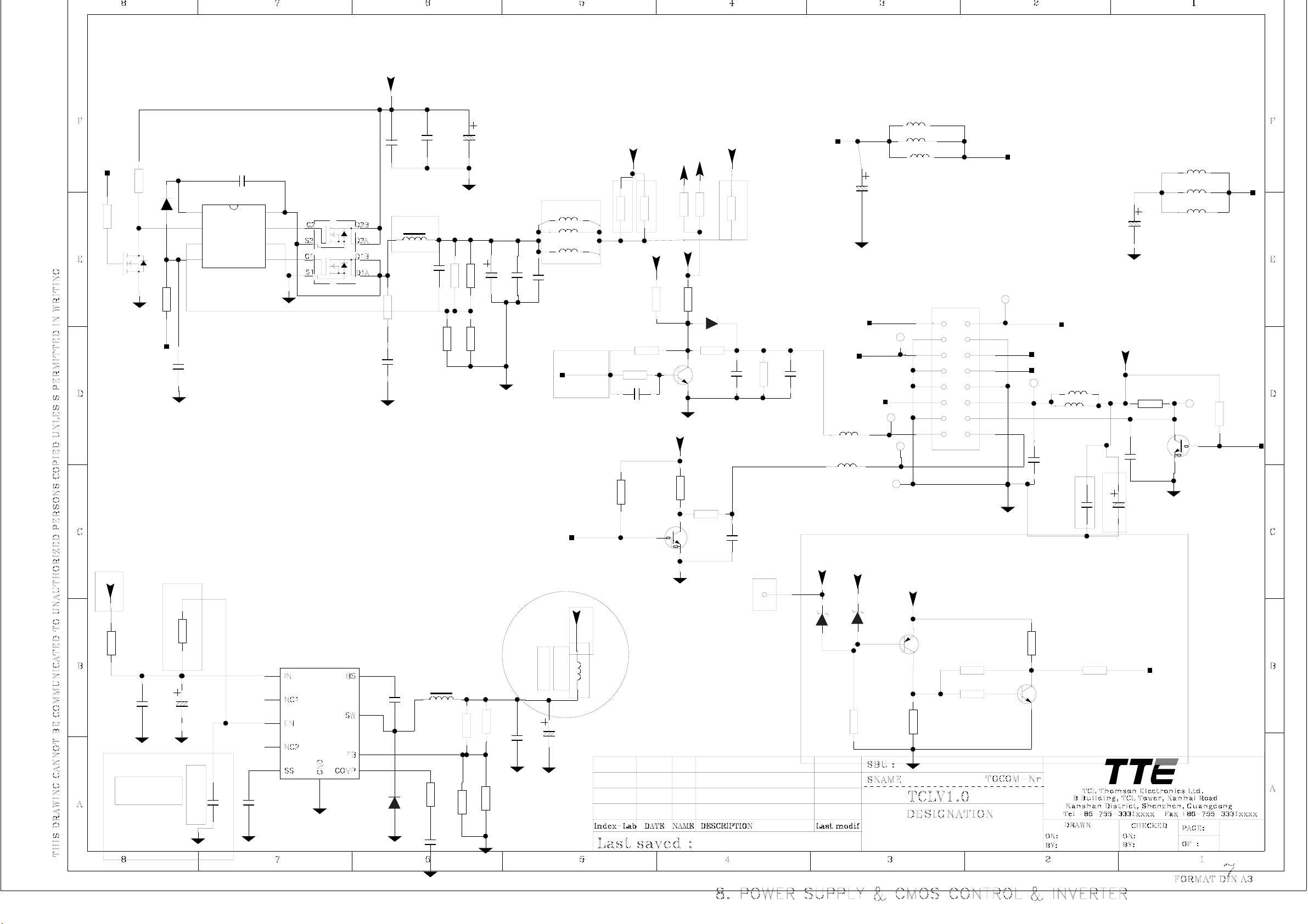
12V_IN
PW_CTL
5VSTB
NC/0R
R841
R824
NC/0R
AGND
R842
20K
Q804
2N7002
5VSTB
C881
0.1U
NC
C894
0.1U
D803
LL4148
U805
1
BOOT
2
DRIVE
36
FB GND
4
VCC
PHASE
UGATE
LGATE
8
7
5
RT8110
R843
10R
AGND
C895
1U
AGND
If want 1.26V,must adjust R&C
R830
10K
U803
4
1
9
3
10
C879
0.01U
NC
AGND
AGNDAGND
C808
NC/330U
16V
AGND
0.1U
C880
NC
about 1mm
PHKD13N03LT
4
3
2
1
5
6
7
8
U804
Backup for +5VUSB,
2
5
7
8
6
NC/MP1411
AGND
NC/SR23
C891
D801
1000P
AGND
AGND
L800
R846
10R
0.01U
C885
15UH
NC
NC
C882
NC
NC
0.1U
C888
4U7
0.01U
R847
L807
NC/10UH
3900P
AGND
C890
100K
10K
R831
NC/10K
NC
C878
NC
16V
R848
R837
NC
220U
AGND
R845
100K
NC
R844
220R
NC
R838
NC?2K26
AGND
C893
NC
1K2
NC
C886
330U
10V
AGND
R836
10K
NC
AGND
R833
NC/2K26
10U
C877
0.1U
C889
NC
L821
L820
AGND
L822
30R
30R
30R
C865
0.1U
PWM1
C887
NC/330U
10V
ON_PBACK
VCC_1.26V
L830
30R
10K
R834
+5V
0.27R
NC
R814
4K7
C896
0.47U
R811R810
0.27R
+3.3AVDD
10K
R818
R829
/NC1K
L805
30R
L806
30R
L804
30R
Backup for disturb
12V
30R
L831
L832
AMP_12V +18V
C899
220U
25V
L833
30R
30R
R849
0R
+5V_USB1
R850
+5V
+5V/DVD
+5V_USB2
0R
R839
12V_IN
C262
220U
25V
0R
AGND
AGND
Z808
10K
D802
R819
LL4148
R813
10K
C
Q802
B
BT3904
E
AGND
+5V
10K
R835
R817
100R
C
Q801
B
C144ET
E
AGND
C876
1U
0.1U
C870
R840
/NC
10K
A78
C898
1
10U
D805
24V_IN
8V2
L825
120R
L826
120R
NC
D804
R857
12V_IN
4K7
8V2
12V
Z811
DIM
+18V
Z813
Z812
T
5VST
T
T
Z806
T
+3.3VSTB
B
R856
12
3
5
7
9
11
13
15
P803
BL_ON
E
BT3906
Q806
C
0R
4K7
R854
R855
20K
T
+18V
4
12V
6
12V
8
10
5VST
12
14
T
P_ON
Z807
L823
30R
L824
30R
16
1U
C873
AGND
R853
10K
C
Q807
B
BT3904
E
4K7
0.1U
R858
C875
5VSTB
C871
47U
INT
0.1U
16V
R822
C874
4K7
Q803
AGND
Z809
T
C
B
E
R823
10K
PW_CTL
AGND
E
2007-01-10
2006-10-08
Hengtao Hiu
13
Page 24

SC1-L
SC1-R
5V-IF
100U
16V
AGND
R455
C276
33K
R456
33K
C277
L210
220R
C279
L211
2U2
220R
R458
2U2
10K
C278
0.1U
AGND
R459
10K
C280
0.1U
C281
AGND
6
7
8
100P
R460
10K
U702
TDA1308T
R454
100R
C274
100U
16V
C275
0.1U
R457
10K
C282
100P
AGND
45
3
2
1
C272
47U
AGND
16V
47U
C273
16V
R452
R453
10K
10K
AGND
AGND
C270
NC
2200P
R450
2K2
PVR-L
PVR-R
R451
C271
2K2
2200P
NC
AGND
68K
R449
C268
10U
CVBSOUT1
B
R448
C269
22K
47P
NC
DVD/SOG
DVD/Y
DVD/U
DVD/V
5V-IF
330R
0.1U
R446
E
BT3906
B
C
Q208
Q207
C
BT3904
R445
E
220R
R447
75R
AGND
R294
NC/470R
R295
NC/47R
C267
C266
47U
16V
AGND
75R
R444
For PVR(NC)
FOR DVD-COMB OR PVR
R291
NC/0R
R292
NC/47R
R293
NC/47R
R289
R290R288
NC/75R
NC/75R
PVR-CVBS
NC/75R
AGND
NC/560P
L201
500R
Y
U
V
C263
C264
NC/560P
C265
NC/560P
5VSTB
IR_SYNC
R296
4K7
C
Q204
B
BT3904
E
R297
4K7
DVD/R
L202
500R
DVD/L
L203
500R
Y
L204
500R
U
L205
500R
V
12V_IN
+5V/DVD
TXD1
RXD1
100P
C261
NC/0R
R298
R299
NC/0R
SPDIF
AUDIO-R
AGND
AUDIO-L
Y/G
U/B
V/R
AGND
L206
30R
L207
500R
AGND
PVR-CVBS
PVR-L
PVR-R
CTRL-2
ATV_RESET#
AGND
12V-DVD
+5V/DVD
TXD1-1
RXD1-1
1
2
3
4
5
6
7
8
9
10
11
12
13
P207
1
2
3
4
5
6
7
IR
8
9
10
11
12
P208
5V-IF
L212
30R
R463
4K7
R461
4K7
FORWARD
REV REV_T
CECT C_CECT
12V_IN
R462
4K7
R464
4K7
R465
4K7
4K7
R466
AGND
for camera
AGND
P209
3 CVBS
2
GND
1
12V
R273
CAMERA/Y
1
2
3
4
5
6
P211
47R
CTRL-1
R275
1K
L209
500R
L208
330P
NC
C259
75R
AGND
12V_IN
R248
R250
D18
D5V0S1
Q205
D
S
G
ML6401
R249
4K7
4K7
C
Q206
B
BT3904
E
AGND
30R
DVD-COMB/CAMERA
Page 25

Page 26

Power Logic Sequence
P803
+18v 1 2 +18v for Audio
Power Supply Unit
GND 3 4 GND
inverter 24v
+5V_USB1/2
12V 5 6 12V
GND 7 8 12V
GND 9 10 GND
5VST 11 12 5VST 5VSTB
GND 13 14 P-ON
DIM
15 16 BL-ON U803 1.26V
CPU/DECODER/SCA
U805/U804 +5V/DVD
+5V
U800
PW_CTL
U300
NNER
ON_Panel vcc_panel
+3.3VSTB
on-pback
ADPP/AVDD/VDD-MPLL
U801 3.3V AVDD
U802
2.6V VM
Panel
Page 27

YN
check 3 control
voltages(power-
on/off,panel-on/off,on-
pback,) if OK,
NY N
No Working
LED if Lighting
check 5vstb voltage
if OK
check
relevant
circuitry
check working conditions of U300 if OK
I2C BUS
wokring if
OK
U301/U302/U305 power
supply and SCL/SDA
Power supply if
OK
Fig1. No Working
Check the relevant
circuitry,e.g.power
supply B.D
crystal/Reset
circuitry working if
OK
Page 28

Check
relevant
signal
channel
Defect Picture
Check LVDS
interface
assembly if OK
check if all
signal resources
have defect
picture
all signal channel defect
Replace the LVDS line, if the
defect picture still have
Y
replace the panel
or U300
Fig2. Defect Picture
Page 29

AV input if have picture
NY
check P302 if assemble
regular
YYN
No Picture
Test waveform of
Pin54/55 of U300 if
have regular signal
input
check Q805 Vcc-panel
power supply and
relevant if regular
YYN
Check P803's Pin16
BL_ON if high level,
over 3V is regular.
NN
check Q801 and U300's
working conditions if
regular.
Y
Replace U300
Replace
U300
check waveform of
pin1/2 of U600 if
regular
check
waveform
of Z600's
Pin8 if
regular
replace Tuner Z600
Replace
U600
Fig3. No Picutre
Page 30

Picture Good,but No Sound
increase the volume and press the
mute key on remote control
test waveform of Pin27/28/29/30 of
U700 if OK
YN
Test waveform of
Pin6/9/10/11 of u700 if
OK
YN YN
Check the
speakers
if 3.3V/12V no voltage
or low voltage,check
relevant circuitry
Fig4.Picture OK, but No Sound
Check the power supply
voltage of U700 and mute
control circuitry if
regular
Check voltage of Pin23 of
U700 and Q700/Q701 and
relevant mute circuitry
test waveform of
Pin54/Pin55 of U300 if
regular
Replace
U300
check the pin23/24
of U600 input if
normal
NY
check
Z600/Z601
replace
U600
Page 31

1. check the inverter voltage 24V if supply for Panel,also view the panel if
have backlight. If have backlight,it shows that have inverter voltage supply.
2. Check if have voltage of Vcc-panel for CMO panel. LG-PHILIPS L32OW 12V. Some
other small size panel is 3.3V.
3.Test waveform of LVDS if OK, LVDS OK but no display, replace the panel.
attention: Do no remove off the LVDS connector when the TV working or contact
U300 only time,to avoid shock U300.
Page 32

Page 33

Page 34

Page 35

Page 36

Page 37

Page 38

Page 39

Mstar Confidential
for TCL
Internal Use Only
Attention Please: Under the technology license agreement between MStar and Dolby/SRS/BBE, MStar is obliged not to
provide samples that incorporate Dolby/SRS/BBE technology to any third party who is not a qualified licensee of
Dolby/SRS/BBE respectively.
UXGA/WSXGA+ LCD TV Controller with VIF
Preliminary Data Sheet Version 0.1
MST6M19GL
FEATURES
Ÿ Single display LCD TV controller with PC &
multimedia display functions
Ÿ Input supports up to SXGA & 1080P
Ÿ Panel supports up to UXGA(1600x1200) /
WSXGA+(1680x1050)
Ÿ TV decoder with 3-D comb filter
Ÿ Multi-standard TV sound demodulator and
decoder
Ÿ 10-bit triple-ADC for TV and RGB/YPbPr
Ÿ 10-bit video data processing
Ÿ Integrated DVI/HDCP/HDMI compliant
receiver
Ÿ High-quality scaling engine & 3-D video
de-interlacer
Ÿ MStarACE-3 picture/color processing engine
Ÿ Embedded On-Screen Display (OSD) controller
engine
Ÿ Built-in MCU supports PWM & GPIO
Ÿ Built-in dual-link 8/10-bit LVDS transmitter
Ÿ 5-volt tolerant inputs
Ÿ Low EMI and power saving features
Ÿ 256-pin LQFP
n NTSC/PAL/SECAM Video Decoder
Ÿ Supports NTSC M, NTSC-J, NTSC-4.43, PAL
(B,D,G,H,M,N,I,Nc), and SECAM
Ÿ Automatic TV standard detection
Ÿ Motion adaptive 3-D comb filter for NTSC/PAL
Ÿ 8 configurable CVBS & Y/C S-video inputs
Ÿ Supports Closed-caption, and V-chip
Ÿ Macrovision detection
Ÿ CVBS video output
n Video IF for Multi-Standard Analog TV
Ÿ Digital low IF architecture
Ÿ Stepped-gain PGA with 26 dB tuning range
and 1 dB tuning resolution
Ÿ Maximum IF analog gain of 37 dB in additional
to digital gain
Ÿ Programmable TOP to accommodate different
tuner gain to optimize noise and linearity
performance
n Multi-Standard TV Sound Decoder
Ÿ Supports BTSC/A2/EIA-J demodulation and
decoding
Ÿ FM stereo & SAP demodulation
Ÿ L/Rx4, mono, and SIFx2 audio input
Ÿ L/Rx3 loudspeaker and line output
Ÿ Supports sub-woofer output
Ÿ Built-in audio output DAC’s
Ÿ Audio processing for loudspeaker channel,
including volume, balance, mute, tone, EQ,
and virtual stereo/surround
Ÿ Optional advanced surround available
(Dolby1, SRS2, BBE3… etc)
n Digital Audio Interface
Ÿ I2S digital audio input & output
Ÿ S/PDIF digital audio input & output
Ÿ HDMI audio channel processing capability
Ÿ Programmable delay for audio/video
synchronization
n Analog RGB Compliant Input Ports
Ÿ Three analog ports support up to 150MHz
Ÿ Fast blanking and function selection switch
support full SCART functions
Ÿ Supports HDTV RGB/YPbPr/YCbCr up to 1080P
Ÿ Supports Composite Sync and SOG
(Sync-on-Green) separator
Ÿ Automatic color calibration
n DVI/HDCP/HDMI Compliant Input Port
Ÿ Supports TMDS clock up to 225MHz @ 1080P
60Hz with 12-bit deep-color resolution
Ÿ Single link on-chip DVI 1.0 compliant receiver
Ÿ High-bandwidth Digital Content Protection
(HDCP) 1.1 compliant receiver
1
Trademark of Dolby Laboratories
2
Trademark of SRS Labs, Inc.
3
Registered trademark of BBE Sound, Inc.
Note
Version 0.1 - 1 - 8/20/2007
Copyright © 2007 MStar Semiconductor, Inc. All rights reserved.
Page 40

Mstar Confidential
for TCL
Internal Use Only
Ÿ High Definition Multimedia Interface (HDMI)
1.3 compliant receiver with CEC support
Ÿ Long-cable tolerant robust receiving
Ÿ Support HDTV up to 1080P
n Auto-Configuration/Auto-Detection
Ÿ Auto input signal format and mode detection
Ÿ Auto-tuning function including phasing,
positioning, offset, gain, and jitter detection
Ÿ Sync detection for H/V Sync
n Digital Video Input
Ÿ One 4:2:2 ITU-R BT.656 8-bit digital video
input port
n High-Performance Scaling Engines
Ÿ Fully programmable shrink/zoom capabilities
Ÿ Nonlinear video scaling supports various
modes including Panorama
n Video Processing & Conversion
Ÿ 3-D motion adaptive video de-interlacer
Ÿ Edge-oriented adaptive algorithm for smooth
low-angle edges
Ÿ Automatic 3:2 pull-down & 2:2 pull-down
detection and recovery
Ÿ MStar 3rd Generation Advanced Color Engine
(MStarACE-3) automatic picture enhancement
gives:
Ÿ Brilliant and fresh color
Ÿ Intensified contrast and details
Ÿ Vivid skin tone
Ÿ Sharp edge
Ÿ Enhanced depth of field perception
Ÿ Accurate and independent color control
Ÿ sRGB compliance allows end-user to
experience the same colors as viewed on CRTs
and other displays
Ÿ Programmable 12-bit RGB gamma CLUT
Ÿ 3-D video noise reduction
Ÿ Frame rate conversion
n On-Screen OSD Controller
Ÿ 16/256 color palette
Ÿ 256/512 1-bit/pixel font
Ÿ 128/256 4-bit/pixel font
Ÿ Supports texture function
Ÿ Supports 4K attribute/code
Ÿ Horizontal and vertical stretch of OSD menus
Ÿ Pattern generator for production test
Ÿ Supports OSD MUX and alpha blending
Ÿ Supports blinking and scrolling for closed
n LVDS/TTL Panel Interface
Ÿ Supports 8/10-bit dual link LVDS up to
Ÿ Supports 8-bit single TTL panel
Ÿ Supports 2 data output formats: Thine & TI
Ÿ Compatible with TIA/EIA
Ÿ With 6/8 bits options
Ÿ Reduced swing for LVDS for low EMI
Ÿ Supports flexible spread spectrum frequency
n Integrated Micro Controller
Ÿ Embedded 8032 micro controller
Ÿ Configurable PWM’s and GPIO’s
Ÿ Low-speed ADC inputs for system control
Ÿ SPI bus for external flash
Ÿ Supports external MCU option controlled
n External Connection/Component
Ÿ SD/MMC/MS/MSPro card reader interface to
Ÿ Two USB controllers (1.1 OTG and 2.0 host)
Ÿ 16-bit data bus for external frame buffer (SDR
Ÿ All system clocks synthesized from a single
Note: Please see Ordering Guide for details on advanced
surround.
UXGA/WSXGA+ LCD TV Controller with VIF
capability
caption applications
UXGA(1600x1200) / WSXGA+(1680x1050)
data mappings
with 360Hz~11.8MHz and up to 25%
modulation
through 4-wire double-data-rate direct MCU
bus or 8-bit direct MCU bus
support JPEG playback
with the flexibility for connecting external
storage devices or PictBridge
or DDR DRAM)
external clock
MST6M19GL
Preliminary Data Sheet Version 0.1
Version 0.1 - 2 - 8/20/2007
Copyright © 2007 MStar Semiconductor, Inc. All rights reserved.
Page 41

Mstar Confidential
for TCL
Internal Use Only
GENERAL DESCRIPTION
The MST6M19GL is a high performance and fully integrated IC for multi-function LCD monitor/TV with
resolutions up to UXGA(1600x1200) / WSXGA+(1680x1050). It is configured with an integrated
triple-ADC/PLL, an integrated DVI/HDCP/HDMI receiver, a multi-standard TV video and audio decoder, a video
de-interlacer, a scaling engine, the MStarACE-3 color engine, an on-screen display controller, an 8-bit MCU and
a built-in output panel interface. By use of external frame buffer, 3-D video decoding and processing are
fulfilled for high-quality TV applications. To further reduce system costs, the MST6M19GL also integrates
intelligent power management control capability for green-mode requirements and spread-spectrum support for
EMI management.
UXGA/WSXGA+ LCD TV Controller with VIF
Preliminary Data Sheet Version 0.1
MST6M19GL
Version 0.1 - 3 - 8/20/2007
Copyright © 2007 MStar Semiconductor, Inc. All rights reserved.
Page 42

Mstar Confidential
for TCL
Internal Use Only
PIN DIAGRAM (MST6M19GL)
MST6M19GL
UXGA/WSXGA+ LCD TV Controller with VIF
Preliminary Data Sheet Version 0.1
GND
REXT
HSYNC1
VSYNC1
VCLAMP
REFP
REFM
BIN1P
SOGIN1
GIN1P
RIN1P
VCOM2
BIN0P
VCOM3
GIN0P
SOGIN0
RIN0P
AVDD_33
GND
HSYNC0
VSYNC0
VSYNC2
BIN2P
SOGIN2
GIN2P
RIN2P
CVBS3
CVBS2
CVBS1
VCOM1
CVBS0
VCOM0
AVDD_33
CVBSOUT1
CVBSOUT0
GND
GPIOL[0]
GPIOL[1]
GPIOL[2]
GPIOL[3]
GPIOL[4]
XOUT
XIN
AVDD_MPLL
GND_VIFPLL
VR27
VR12
AVDD_RXS
GND_RXS
SIFP
SIFM
VIFM
VIFP
GND_RXV
AVDD_RXV
TAFC
AVDD_TAGC
GND_TAGC
TAGC
AVDD_AU
GND
VDDP
LVB0M
LVB0P
LVB1M
LVB1P
LVB2M
LVB2P
233
88
GPIOD[0]
232
231
899192
90
GPIOD[1]
GPIOD[2]
LVBCKM
230
229
GPIOD[3]
GPIOD[4]
GPIOE[2]
GPIOE[0]
GPIOE[1]
DDCD_SCL
DDCD_SDA
HPLUG
RX2P
RX2N
GND
RX0P
RX0N
AVDD_33
RXCKN
RX1N
RX1P
GND
256
255
254
253
252
250
251
249
1
2
3
4
5
6
7
8
9
10
11
12
13
14
15
16
17
18
19
20
21
22
23
24
25
26
27
C1
28
Y1
29
C0
30
Y0
31
32
33
34
35
36
37
38
39
40
41
42
43
44
45
46
47
48
49
50
51
52
53
54
55
56
57
58
59
60
61
62
63
64
Pin 1
6566676869
GND
AUVRP
AUVRM
71
70
72
AUVAG
AVDD_AU
LINE_IN_0L
LINE_IN_1L
LINE_IN_0R
RXCKP
244
248
73
243
246
247
245
77
78
75
74
76
AUCOM
LINE_IN_3L
LINE_IN_2L
LINE_IN_1R
LINE_IN_2R
LINE_IN_3R
GPIOE[3]
VDDC
240
239
236
238
237
85
838486
LINE_OUT_1L
LINE_OUT_2R
LINE_OUT_1R
234
235
87
LINE_OUT_0L
LINE_OUT_0R
242
241
81
82
79
80
LINE_OUT_3L
LINE_OUT_2L
LINE_OUT_3R
LINE_IN_MONO
LVB4P
LVBCKP
LVB3M
LVB3P
LVB4M
GND
VDDP
LVA0M
LVA0P
LVA1M
LVA1P
LVA2M
LVA2P
LVACKM
LVACKP
LVA3M
LVA3P
LVA4M
227
225
223
221
218
216
228
226
224
222
220
219
MST6M19GL
XXXXXXXX
XXXXX
94
96
98
93
95
97
99
100
101
102
GND
VDDP
VDDC
AD[0]
AD[1]
AD[2]
GPIOD[5]
GPIOD[7]
GPIOD[6]
AD[3]
214
217
215
213
212
211
103
105
107
104
106
108
109
110
ALE
RDZ
WRZ
GND
RASZ
VDDC
BADR[1]
BADR[0]
DI[7]
DI[6]
DI[5]
DI[4]
VDDP
DI[3]
DI[2]
DI[1]
DI[0]
VDDP
PWM2
PWM3
ICLK
LVA4P
VDDC
GND
HWRESET
210
209
207
206
205
208
204
203
202
201
111
112
114
115
116
113
117
118
119
120
WEZ
CASZ
MADR[9]
MADR[8]
MADR[7]
MADR[6]
AVDD_MI
MADR[11]
MADR[10]
MADR[5]
GPIOT[0]
200
198
196
199
121
122
194
197
195
193
192
GPIOB[1]
191
GPIOB[0]
190
USB_CID
189
USB_DP
188
USB_DM
187
USB_VBUS
186
VDDP
185
IRIN
184
INT
183
DDCA_SCL
182
DDCA_SDA
181
DDCR_SCL
180
DDCR_SDA
179
PWM1
178
PWM0
177
SAR3
176
SAR2
175
SAR1
174
SAR0
173
VDDC
172
GND
171
SPI_SDO
170
SPI_SCZ
169
SPI_SDI
168
SPI_SCK
167
GND
166
VDDP
165
GND
164
USB20_DP
163
USB20_DM
162
AVDD_USB
161
USB20_REXT
160
MVREF
159
MCLKE
158
MCLK
157
MCLKZ
156
DQM1
155
DQS1
154
AVDD_MI
153
MDATA[15]
152
MDATA[14]
151
MDATA[13]
150
MDATA[12]
149
AVDD_MI
148
MDATA[11]
147
MDATA[10]
146
GND
145
MDATA[9]
144
MDATA[8]
143
AVDD_MI
142
MDATA[7]
141
MDATA[6]
140
MDATA[5]
139
MDATA[4]
138
AVDD_MI
137
MDATA[3]
136
MDATA[2]
135
GND
134
MDATA[1]
133
MDATA[0]
132
AVDD_MI
131
DQS0
130
DQM0
129
GPIOR[0]
123
125
127
124
126
128
GND
MADR[4]
MADR[1]
MADR[3]
MADR[2]
MADR[0]
AVDD_MI
AVDD_MIPLL
Version 0.1 - 4 - 8/20/2007
Copyright © 2007 MStar Semiconductor, Inc. All rights reserved.
Page 43

08-PW37C03-PWYA
H3-HE9AN5B-YM0A L32E9A/MS91-AP/SS5
ASS PART NO. SEPC LOCATION
08-PW37C03-PWYA 10-0001H8-FBX DIODE 1H8 (FAST RECOVERY) DB1
08-PW37C03-PWYA 10-0FR104-FBX DIODE FR104 (FAST RECTIFIER) DB3;DB2
08-PW37C03-PWYA 10-0RL255-EBX
08-PW37C03-PWYA 10-1N4007-EBX DIODE IN4007 DB7
08-PW37C03-PWYA 13-000TL4-31T IC-REGSPECKT TL431ACLP R=N IC7;IC8;IC9
08-PW37C03-PWYA 18-CD0102-JNX RES. C.F. 1K OHM 1/4W +/-5% RF10
08-PW37C03-PWYA 18-CD0684-JNX
08-PW37C03-PWYA 18-DB0474-FNX
08-PW37C03-PWYA 18-KE0106-JN3
08-PW37C03-PWYA 18-KE0684-JNX
08-PW37C03-PWYA 25-GFB220-M1X
08-PW37C03-PWYA 35-LB1011-0IX FERR BEAD BF-I40110Z-719 L3
08-PW37C03-PWYA 40-5PL37C-PWC1XG TV PCB PW BD R=Y
08-PW37C03-PWYA 41-WJ0050-B00
08-PW37C03-PWYA 41-WJ0060-B00 WIRE-BARE JW1
08-PW37C03-PWYA 41-WJ0075-B00 WIREBAREJUMPER7.5MM J9;J16
08-PW37C03-PWYA 41-WJ0080-B00 WIREBAREJUMPER8MM J18
08-PW37C03-PWYA 41-WJ0100-B00 WIREBAREJUMPER10MM J5;J13
08-PW37C03-PWYA 41-WJ0135-B00 WIREBAREJUMPER13.5MM J23
08-PW37C03-PWYA 41-WJ0140-B00 WIREBAREJUMPER14MM J11
08-PW37C03-PWYA 41-WJ0150-B00 WIREBAREJUMPER15MM J7;J8;J1;J15
08-PW37C03-PWYA 41-WJ0165-B00 WIREBAREJUMPER16.5MM J24
08-PW37C03-PWYA 41-WJ0175-B00 WIREBAREJUMPER17.5MM L2;J2;J3
08-PW37C03-PWYA 66-343730-0B0
08-PW37C03-PWYA 66-343740-0B0
08-PW37C03-PWYA 10-865C08-S7X D-SCH 80V 20A DS2;DS1
08-PW37C03-PWYA 10-BYV296-F7X
08-PW37C03-PWYA 10-P6KE6V-8AX TVS DIODE P6KE6.8A DB4
08-PW37C03-PWYA 10-RS605M-H7X D-BR 600V 6A BD1
08-PW37C03-PWYA 10-SR3100-S0X RECTIFYING TUBE SR3100 DB11
08-PW37C03-PWYA 10-YG865C-S7X DIODE YG865C06R DS4
08-PW37C03-PWYA 11-SK3561-0CX MOSFET 500V 8A QW10;QW9
08-PW37C03-PWYA 11-SK3568-0CX TRANSISTOR 2SK3568 QF6;QF5
08-PW37C03-PWYA 13-PS2561-WFP
08-PW37C03-PWYA 13-VIPER2-2AP IC VIPER22ADIP-E IC1
TV EQU - ASS Y - POWER
BD(PWL37C03A) R=N
DIODE RL255 OR RL206(POWER
RECTIFIER)
RES. C.F. 680K OHM 1/4W +/5%
RES. M.F. 470K OHM 1/6W +/1%
RES. GLASS GLAZE 10M OHM
1/2W +/-5%
RES.GLASS GLAZE 680K 1/2W
+/-5%
CAP.ELEC 22UF/50V
RGA220M1HTA-0511
TCL41-WJ0050-B00= WIRE BARE
JUMPER 5MM R
HOLLOW RIVET
1.6MMX3.0MMX3.2MM
HOLLOW RIVET
(2.3MMX4.0MMX3.5MM)
DIODE 9A 600V FORPFC BYV29600
TCL13-PS2561-WFP=
PHOTOCOUPLER PS2561L1-
D3;D1
RW13
RF12
R2;R1
R5
CB6;CB5;CB12;C11;
C10
J4;J10
FOR L1;FOR T1
FOR C5;FOR P1
D2
IC10;IC5;IC6
Page 44

08-PW37C03-PWYA 18-DF0224-JGX1
08-PW37C03-PWYA 18-NH0108-JLX RES.C.C NKN3W +/-5% 0R1 M15 RF23
08-PW37C03-PWYA 18-P40804-00Y R-WIRE 5MOHM +/-10% 0W RS4;RS6
08-PW37C03-PWYA 22-NTC309-XX1 NTC.RES 3D2-14 TH1
08-PW37C03-PWYA 22-VDR561-XG2
08-PW37C03-PWYA 25-GCA102-M1X
08-PW37C03-PWYA 25-GEA102-M1X CAP. ELEC 1000UF 35V +/-20% CS1;CS2
08-PW37C03-PWYA 25-GEA471-M1X CAP. ELEC 470 UF 35V +/-20% CS3
08-PW37C03-PWYA 25-GNJ151-M1X
08-PW37C03-PWYA 25-KNA220-M1X CAP.ELEC 450V 22UF CB1
08-PW37C03-PWYA 25-NCA102-M1X
08-PW37C03-PWYA 26-AIL103-MEX CAP.CER 10NF 500V +/-20% CB13
08-PW37C03-PWYA 26-AKL103-MFX CAP. CER 10 NF 1KVDC +/-20% CB2
08-PW37C03-PWYA 26-AKM101-KRX CAP.CER 100PF 1KV +/-10% CB3
08-PW37C03-PWYA 26-AKM221-KRX CAP. CER 220 PF 1KV +/-10% CW7
08-PW37C03-PWYA 26-AMM221-KRX CAP.CER 220PF 2KV +/-10% CF11
08-PW37C03-PWYA 26-APK102-ME3
08-PW37C03-PWYA 26-APK471-KB4
08-PW37C03-PWYA 27-AKQ333-J0B CAP.PP 33N/1KV+/_5% CW6
08-PW37C03-PWYA 27-AQQ474-KV3 FILM CAP. 0.47UF 275VAC CX2
08-PW37C03-PWYA 27-AQQ684-KV6 CFS 0.68UF 275V X2 CX1
08-PW37C03-PWYA 27-AWQ474-J0X CAP.PP 470NF 450V +/-5% C3;C4
08-PW37C03-PWYA 27-MHW104-K0X
08-PW37C03-PWYA 35-FB1690-304 MAGNETIC CORE
08-PW37C03-PWYA 36-LIF152-XX0 PFC COIL. JLC3574 L1
08-PW37C03-PWYA 36-LIF153-XX0 LINE FILTER LGH-(9X2)MH LF3;LF2
08-PW37C03-PWYA 36-TRF301-LX0
08-PW37C03-PWYA 36-TRF315-LX0 TRANSFORMER CONV BCK-35-499D T1
08-PW37C03-PWYA 36-WID229-XX0 COIL WIDTH LC-2R2-TCL LB1
08-PW37C03-PWYA 36-WID249-XX0 COIL WIDTH 2.4UH FLC0514 LS2
08-PW37C03-PWYA 36-WID629-XX0 COIL WIDTH LC-6R2-TCL LS3
08-PW37C03-PWYA 46-35087W-01XG PIN BASE *1 187 H06;H05;H07
08-PW37C03-PWYA 46-38604W-16XG PIN BASE TU2005WNR-2X8 P4
08-PW37C03-PWYA 46-38604W-28XG CONN EH 28 2.54MM FEMALE R P5
08-PW37C03-PWYA 46-39219W-03XG PIN BASE VH-3AW P1
08-PW37C03-PWYA 50-05000D-6GS3G FUSE 5A 250V F1
08-PW37C03-PWYA 64-B30080-104G M/C SCREW B 3 X 8
METAL FILM FIXED RESISTOR
1WS 220KΩ
VARISTOR RESISTANCE
14D561K-M
CAP. ELEC 1000 UF 16V +/-20%
105
CAP. ELEC 150UF 450V +/-20%
(30X30)
CE 105 HIGH RIPPLE & LR
0.001F 16V
CAP. CER 1000PF 400VAC+/-20%
E
TCL26-APK471-KB4= CAP. CER
470 PF 250VAC
CAP. M.P.E 0.1 UF 400V +/10%
TRANSFORMER CONV. BCK-25002T
RB3
VR1
CS7;CS6;CB8;CS5
C5
CB7
CY4
CY1;CY2;CY3
CF10
FOR D2 正负极;FOR
QF5 D极;FOR QF6 D
极
T2
FOR QW10;FOR
BD1;FOR QW9;FOR
DS4
Page 45

FOR D2;FOR
08-PW37C03-PWYA 64-B30080-104G M/C SCREW B 3 X 8
08-PW37C03-PWYA 64-Z30080-112G MACHINE SCREW FOR HS
08-PW37C03-PWYA 66-20516X-0B0 FUSE HOLDER FOR F1
08-PW37C03-PWYA 67-H83829-0A0 RAW HEATSINK -- 00 00 R=Y FOR DS4
08-PW37C03-PWYA 67-H83829-1A0 RAW HEATSINK -- 01 00 R=Y
08-PW37C03-PWYA 67-H83829-2A0 RAW HEATSINK -- 02 00 R=Y FOR DS1 & DS2
08-PW37C03-PWYA 67-H83829-3A0 RAW HEATSINK -- 03 00 R=Y FOR QW9 & QW10
08-PW37C03-PWYA 67-H83829-4A0 RAW HEATSINK -- 04 00 R=Y FOR BD1
08-PW37C03-PWYA 67-M60442-0E0 METAL PART H04;H03;H02;H01
08-PW37C03-PWYA 71-268390-0A0AF LABEL (QC) GREEN
08-PW37C03-PWYA 71-PHIBAR-NUL1A TV PRI LABEL BARCODE -- R=Y
08-PW37C03-PWYA 09-55C13V-DTX SMD.DIODE 13V Z1;ZS4;DB8
08-PW37C03-PWYA 09-55C27V-DTX SMD.DIODE 27V/SOD80 ZS5
08-PW37C03-PWYA 09-55C33V-DTX SMD.DIODE BZV55-C33 DB10
08-PW37C03-PWYA 09-GLZ20B-DTX SMD Diode GLZ20B DB5
08-PW37C03-PWYA 09-LL4148-ATX SMD. SWITCHING DIODE LL4148
08-PW37C03-PWYA 09-LL4148-ATX SMD. SWITCHING DIODE LL4148 DW4;DW3;DW6
08-PW37C03-PWYA 09-MBRX14-STX DIODE MBRX140 D4
08-PW37C03-PWYA 12-2N7002-0BX SMD TRANSISTOR 2N7002 Q1
08-PW37C03-PWYA 12-BT3904-0BX
08-PW37C03-PWYA 12-BT3906-0BX
08-PW37C03-PWYA 12-S4160T-0BX SMD.TRANSISTOR PBSS4160T Q12;QF3
08-PW37C03-PWYA 12-S5160T-0BX SMD.TRANSISTOR PBSS5160T Q11;QF4
08-PW37C03-PWYA 13-0L6563-00B IC L6563 IC2
08-PW37C03-PWYA 13-0LM393-M0B IC LM393M IC4
08-PW37C03-PWYA 13-L6599D-00B IC L6599D IC3
08-PW37C03-PWYA 19-AB0102-FTX
08-PW37C03-PWYA 19-AB0102-JTX RES SMD 1K OHM 1/10W 0603
08-PW37C03-PWYA 19-AB0103-JTX RES SMD 10K OHM 1/10W 0603 RS18;RS17
08-PW37C03-PWYA 19-AB0105-JTX RES SMD 1M OHM 1/10W 0603 RS8
08-PW37C03-PWYA 19-AB0106-JTX
08-PW37C03-PWYA 19-AB0163-FTX
08-PW37C03-PWYA 19-AB0202-FTX
08-PW37C03-PWYA 19-AB0202-JTX
08-PW37C03-PWYA 19-AB0203-FTX
08-PW37C03-PWYA 19-AB0222-JTX RES SMD 2.2K OHM 1/10W 0603 RS21;RS22
SMD. TRANSISTOR
MMBT3904LT1(NPN)
SMD. TRANSISTOR
MMBT3906LT1(PNP)
RES SMD 1K OHM 1/10W +/-1%
0603
SMD. RES 10M OHM 1/10W +/-5%
0603
SMD.RES 16K OHM 1/6W +/-1%
0603
SMD. RES 2K OHM 1/10W +/-1%
0603
SMD. RES 2K OHM 1/10W +/-5%
0603
0603 RES. SMD 20K OHM 1/16W
+/-1%
DS1;FOR DS2;FOR
QF5;FOR QF6
FOR QF5 & QF6 &
D2
DB9;DS9;DS8;DS7;D
S11;DF5;DF4;DS10;
DW7
QS2;QS3
QS4;QS1
RB11;RB10
RS2;RS10;RB8;RS34
;RS29;RS35;RS20
RS36
RS12
RS14
RS16
RS25;RS26
Page 46

08-PW37C03-PWYA 19-AB0333-FTX
08-PW37C03-PWYA 19-AB0333-JTX RES. SMD 33K OHM 1/10W 0603 RB9
08-PW37C03-PWYA 19-AB0391-JTX SMD RES 390 OHM 1/10W 0603 RS23;RS28
08-PW37C03-PWYA 19-AB0472-JTX RES SMD 4.7K OHM 1/10W 0603 RS1;RS19
08-PW37C03-PWYA 19-AB0621-FTX SMD.RES 620 OHM +/-1% 1/10W RS24
08-PW37C03-PWYA 19-BC0000-JTX SMD.RES 0 OHM 1/8W +/-5% RS33
08-PW37C03-PWYA 19-BC0101-JTX SMD.RES100 OHM 1/8W +/-5% RB7;RW11
08-PW37C03-PWYA 19-BC0102-JTX SMD.RES 1K OHM 1/8W +/-5% R18;RS15
08-PW37C03-PWYA 19-BC0103-FTX SMD.RES 10K OHM 1/8W +/-1% RF6
08-PW37C03-PWYA 19-BC0103-JTX SMD. RES 10K OHM 1/8W +/-5% RS11
08-PW37C03-PWYA 19-BC0123-JTX SMD.RES 12K OHM 1/8W +/-5% RF9
08-PW37C03-PWYA 19-BC0202-JTX SMD.RES 2K OHM 1/8W +/-5% RW10
08-PW37C03-PWYA 19-BC0225-JTX SMD.RES 2.2M OHM 1/8W +/-5% RW14
08-PW37C03-PWYA 19-BC0241-JTX SMD.RES 240 OHM 1/8W +/-5% RW15
08-PW37C03-PWYA 19-BC0331-JTX SMD.RES 330 OHM 1/8W +/-5% RW18
08-PW37C03-PWYA 19-BC0332-JTX SMD.RES 3.3K OHM 1/8W +/-5% RW12
08-PW37C03-PWYA 19-BC0393-FTX SMD.RES 39K OHM 1/8W +/-1% RF3
08-PW37C03-PWYA 19-BC0393-JTX SMD.RES 39K OHM 1/8W +/-5% RF8
08-PW37C03-PWYA 19-BC0394-JTX SMD.RES 390K OHM 1/8W +/-5% RF7
08-PW37C03-PWYA 19-BC0472-JTX
08-PW37C03-PWYA 19-BC0621-FTX SMD.RES 620 OHM 1/8W +/-1% RS27
08-PW37C03-PWYA 19-BC0822-FTX SMD.RES 8.2K OHM 1/8W +/-1% RW7
08-PW37C03-PWYA 19-BC0912-FTX
08-PW37C03-PWYA 19-BC1272-FTX
08-PW37C03-PWYA 19-CD0000-JTX RES.SMD 0 OHM 1206 RF24;RF25
08-PW37C03-PWYA 19-CD0100-JTX RES. MELF 10 OHM 1/4W +/-5% RF18
08-PW37C03-PWYA 19-CD0103-JTX
08-PW37C03-PWYA 19-CD0105-FTX
08-PW37C03-PWYA 19-CD0123-JTX SMD.RES 12K OHM 1/4W +/-5% RW5
08-PW37C03-PWYA 19-CD0152-JTX
08-PW37C03-PWYA 19-CD0153-JTX
08-PW37C03-PWYA 19-CD0279-JTX
08-PW37C03-PWYA 19-CD0330-JTX SMD. RES 33 OHM 1/4W +/-5% RF19;RF20;RW1;RW2
08-PW37C03-PWYA 19-CD0331-JTX SMD. RES 330 OHM 1/4W +/-5% RB6
08-PW37C03-PWYA 19-CD0470-JTX SMD. RES 47 OHM 1/4W 5% RB17;RB4
08-PW37C03-PWYA 19-CD0472-JTX SMD. RES 4.7K OHM 1/4W 5%
08-PW37C03-PWYA 19-CD0473-JTX SMD. RES 47K OHM 1/4W 5% RB16;RB15
08-PW37C03-PWYA 19-CD0479-JTX SMD.RES 4.7 OHM 1/4W +/-5% RF17
08-PW37C03-PWYA 19-CD0514-FTX SMD.RES 510K OHM 1/4W +/-1% RF11;RF30;RF29
SMD. RES 33K OHM 1/10W +/-1%
0603
SMD. RES 4.7K OHM 1/8W +/5%
SMD.RES 0805,1/8W,±1%,9.1K
Ω
SMD.RES 12.7K OHM 1/8W +/1%
SMD. RES 10KOHM 1/4W +/-5%
1206
SMD.RES 1M OHM 1/4W +/-1%
1206
SMD. RES 1500 OHM 1/4W +/-5%
1206
SMD. RES 15 KOHM 1/4W +/-5%
1206
SMD. RES 2.7 OHM 1/4W +/-5%
1206
RS13
R17;R16
RF16
RF13;RW9
RW3;RF22;RW4;RF21
RF1;RF32;RF31;RF2
7;RF26;RF5;RF4;RF
2
RS5;RS7
RW16
RB5;RB2;RB13;RB1;
R7;R15
RS3;RS9;R14;RS31;
RS30
Page 47

08-PW37C03-PWYA 19-CD0564-FTX 1206 REC 560K OHM 1/4W +/-1% RW6
08-PW37C03-PWYA 19-CD0684-FTX SMD.RES 680K OHM 1/4W +/-1% RW17
08-PW37C03-PWYA 19-CD0824-FTX SMD.RES 820k OHM 1/4W +/-1% RF28;RF15;RF14
08-PW37C03-PWYA 28-AB0104-KBX
08-PW37C03-PWYA 28-AB0104-ZFX
08-PW37C03-PWYA 28-AB0104-ZFX
08-PW37C03-PWYA 28-BA0475-KBX
08-PW37C03-PWYA 28-BB0103-KBX
08-PW37C03-PWYA 28-BB0104-KBX
08-PW37C03-PWYA 28-BB0104-ZFX
08-PW37C03-PWYA 28-BB0105-ZFX SMD. CAP 1UF 50V +80%-20% CS23;CS24
08-PW37C03-PWYA 28-BB0471-JCX SMD. CAP 470PF 50V +/-5% CW23
08-PW37C03-PWYA 28-BB0473-KBX CAP.SMD 0.047UF 50V B +/-10% CB4
08-PW37C03-PWYA 28-BB0681-JCX SMD CAP 680PF 50V +/-5% 0805 CF4
08-PW37C03-PWYA 28-BC0474-KBX
08-PW37C03-PWYA 28-BD0105-KBX SMD.CAP. 25V 1UF +/-10% CF8
08-PW37C03-PWYA 28-BD0105-ZFX SMD CAP 1UF 25V +80-20% CF5;CF1;CW3;CF6
T8-HE9AN5B-LE1 18-CB0472-JNX
T8-HE9AN5B-LE1 18-CB0560-JNX RES. C.F. 56 OHM 1/6W +/-5% R364
T8-HE9AN5B-LE1 40-LM46E9-LEA1XG TV PCB LE BD R=Y
T8-HE9AN5B-LE1 41-WJ0050-B00
T8-HE9AN5B-MA1 25-BBB470-M1X CAP. ELEC 47 UF 10V +/-20% C804;C807
T8-HE9AN5B-MA1 25-BCB100-M1X CAP. ELEC 10 UF 16V +/-20%
T8-HE9AN5B-MA1 25-BCB101-M1X CAP. ELEC 100 UF 16V +/-20% C710;C713;C800
T8-HE9AN5B-MA1 25-BCB220-M1X CAP. ELEC 22 UF 16V +/-20% C806;C805
T8-HE9AN5B-MA1 25-BCB221-M1X CAP. ELEC 220 UF 16V +/-20% C883;C893
T8-HE9AN5B-MA1 25-BCB331-M1X CAP. ELEC 330 UF 16V +/-20% C886;C887;C808
T8-HE9AN5B-MA1 25-BCB470-M1X CAP. ELEC 47 UF 16V +/-20%
T8-HE9AN5B-MA1 25-BDB221-M1X CAP. ELEC 220UF 25V +/-20%
T8-HE9AN5B-MA1 25-BDB470-M1X CAP. ELEC 47 UF 25V +/-20% C709
T8-HE9AN5B-MA1 25-BDB471-M1X CAP. ELEC 470 UF 25V +/-20%
T8-HE9AN5B-MA1 25-BFB479-M1X CAP. ELEC 4.7 UF 50V +/-20% C744
T8-HE9AN5B-MA1 34-R102K2-0EX
SMD. CAP 50VDC 0.1UF +/-10%06CS13;CS14;CS10;CS
22;CS9
CAP. SMD 0.1UF 50V +80%~-20%
F
CAP. SMD 0.1UF 50V +80%~-20%
F
SMD.CAP 4.7UF +/-10%10V
(188605656)
SMD. CAP 10NF 50V +/-10%
0805
SMD. CAP 0.1UF 50VDC +/-10%
0805
SMD CAP. 0.1 UF 50V +80/-20%
0805
SMD. CAP 470 NF 16VDC +/-10%
0805
CARBON RES. C.F. 4.7K OHM
1/6W +/-5%
TCL41-WJ0050-B00= WIRE BARE
JUMPER 5MM R
COIL CHOKE 1000UH/+/-10%
EL0606RA-102K-P
CS16;CS21;CS20;CS
15;CS12;CS11;CS19
;CS18
CS17
CW21
CW20;CF9;CF2
CW4;CW5;CW22;CF7;
CB9;CW9
CS8;CB10;CS4;CB11
CF3
R375
J301
C1;C200;C201;C306
;C638;C639;C647
C712;C711;C871;C6
02;C255;C626;C601
C899;C262;C701;C7
00
C708;C707;C706;C7
05
L606;L607
Page 48

T8-HE9AN5B-IR1 02-IRR002-XX1
T8-HE9AN5B-IR1 25-HCB101-M1X CAP. ELEC 100 UF 16V +/-20% C118
T8-HE9AN5B-IR1 46-35135W-03XG PIN BASE PH-03AW P1
T8-HE9AN5B-IR1 59-829580-000 RUBBER PAD FOR U29
T8-HE9AN5B-LE1 11-SA1015-YBX TRANSISTOR ST2SA1015Y (PNP) Q301
T8-HE9AN5B-LE1 46-35135W-04XG PIN BASE PH-04AW P302
T8-HE9AN5B-LE1 46-38604W-12XG PIN BASE TU2005WNR-2X6 P301
T8-HE9AN5B-MA1 07-380FI5-NA7G
T8-HE9AN5B-MA1 18-FG0150-JHX RES. M.O. 15 OHM 2W +/-5% R600
T8-HE9AN5B-MA1 18-RG0109-JHX
T8-HE9AN5B-MA1 18-RG0278-JHX
T8-HE9AN5B-MA1 45-OSC14M-3Y2 CRYSTAL 14.31818MHZ X300
T8-HE9AN5B-MA1 45-OSC4M0-0N1 CRYSTAL 4MHZ X600
T8-HE9AN5B-MA1 45-SAWK62-74D SAW FILTER K6274D Z602
T8-HE9AN5B-MA1 45-SAWK93-52M SAW FILTER K9352M Z601
T8-HE9AN5B-MA1 46-33079W-06XG PIN BASE *6 TJC3-6A P702
T8-HE9AN5B-MA1 46-35014H-02XG JUMPER WIRE CAP F801
T8-HE9AN5B-MA1 46-35017W-02XG PIN BASE 1*2 PITCH=2.54MM F800;F801
T8-HE9AN5B-MA1 46-35199W-06XG .PH-6A 6PIN PITCH-2.0MM P206
T8-HE9AN5B-MA1 46-35199W-07XG CONN.PH-7A PITCH=2.0MM 7PIN P700
T8-HE9AN5B-MA1 46-35199W-10XG
T8-HE9AN5B-MA1 46-38605W-12XG PIN BASE TU2005WNV-2X6 P304
T8-HE9AN5B-MA1 46-38605W-16XG PIN BASE TU2005WNV-2X8 P803
T8-HE9AN5B-MA1 46-38605W-40XG PIN BASE TU2005WNV-2X20 P302
T8-HE9AN5B-MA1 47-RCA068-XX2G AV SOCKET AV-3.2-2WB-09 P204
T8-HE9AN5B-MA1 47-RCA117-XX2G
T8-HE9AN5B-MA1 47-RCA156-XX2G SOCKET-RCA 2 RD-WH-YE R P200
T8-HE9AN5B-MA1 47-RCA202-XX0G SOCKET RCA AV-3.2-1WB41 P210
T8-HE9AN5B-MA1 47-SVI008-XX1 SOCKET DSW-506WT-L P202
T8-HE9AN5B-MA1 47-VGA018-XX0 SOCKET-VGA 15 R FEMALE P1
T8-HE9AN5B-MA1 67-387190-0A0 HEAT SINK FOR U300
T8-HE9AN5B-MA1 67-S84390-2E0
T8-HE9AN5B-MA1 67-T21456-090 HEAT SINK FOR U800
T8-HE9AN5B-MA1 71-268390-0A0AF LABEL (QC) GREEN
T8-LE9BS5B-SI1 25-BCB101-M1X CAP. ELEC 100 UF 16V +/-20% C190
T8-LE9BS5B-SI1 46-35199W-03XG PIN BASE *3 PITCH=2.0MM P4
T8-LE9BS5B-SI1 46-35199W-05XG CONN.PH-5A 5PIN PITCH=2.0MM J902
T8-LE9BS5B-SI1 46-38605W-06XG 6PIN BASE P1
T8-LE9BS5B-SI1 47-EAR005-XX0
T8-LE9BS5B-SI1 47-RCA009-XX4G AV SOCKET P5
T8-LE9BS5B-SI1 47-USB002-XX0 USB SOCKET USB-1W-B P3
TCL02-IRR002-XX1= IR
RECEIVER MODULE FPS
TUNER TCL F07WP-3DR-E D% PAL
38MHZ
RES. WIRE ROUND 1 OHM 2W +/5%
RES. WIRE ROUND 0.27 OHM 2W
+/-5%
CONN. PH-10 10PIN
PITCH=2.0MM
SOCKET-RCA 6 GN-BL-RD-YW-WHRD R
TV RAW SHIELDING -- -- 02 00
00 R=Y
EARPHONE SOCKET CK3-3.5-3WKE
U29
Z600
R1050;R1051
R811;R810
P303(NEAR PIN1
INSERT)
P203
FOR U300
P2
Page 49

T8-LE9BS5B-SI1 56-841040-0HN1A
T8-LE9BS5B-SI1 58-842490-CUI1B
H3-HE9AN5B-YM0A 09-00SR23-STX SMD.DIODE 30V/2A SR23 SMT SPARE
H3-HE9AN5B-YM0A 09-0BA982-ATX SMD.DIODE BA982-GS08 SMT SPARE
H3-HE9AN5B-YM0A 09-0BAV99-ATX
H3-HE9AN5B-YM0A 09-4148WS-ATX SMD. DIODE 1N4148WS SMT SPARE
H3-HE9AN5B-YM0A 09-55C33V-DTX SMD.DIODE BZV55-C33 SMT SPARE
H3-HE9AN5B-YM0A 09-D5V0S1-BAB SMD.DOIDE PESD5V0S1BA SMT SPARE
H3-HE9AN5B-YM0A 09-D5V0S2-BTB SMD.DOIDE PESD5V0S2BT SMT SPARE
H3-HE9AN5B-YM0A 09-LL4148-ATX SMD. SWITCHING DIODE LL4148 SMT SPARE
H3-HE9AN5B-YM0A 09-RLZ5B6-DTX SMD DIODE RLZ5.6BTE11 SMT SPARE
H3-HE9AN5B-YM0A 09-STZ6V2-NTX SMD.DIODE STZ6.2N SMT SPARE
H3-HE9AN5B-YM0A 12-13N03L-0BX SMD.TRANSISTOR PHKD13N03LT SMT SPARE
H3-HE9AN5B-YM0A 12-2N7002-0BX SMD TRANSISTOR 2N7002 SMT SPARE
H3-HE9AN5B-YM0A 12-A04411-0BX PCHANNEL MOSFET A04411 SMT SPARE
H3-HE9AN5B-YM0A 12-BC846B-0BX TRANSISTOR BC846B SMT SPARE
H3-HE9AN5B-YM0A 12-BT3904-0BX
H3-HE9AN5B-YM0A 12-BT3906-0BX
H3-HE9AN5B-YM0A 12-C143ZT-0BX TRA SIG SM PDTC143ZT SMT SPARE
H3-HE9AN5B-YM0A 12-C144ET-0BX SMD. TRANSISTOR PDTC144ET SMT SPARE
H3-HE9AN5B-YM0A 19-AB0000-JTX
H3-HE9AN5B-YM0A 19-AB0100-JTX RES SMD 10 OHM 1/10W +/-5% SMT SPARE
H3-HE9AN5B-YM0A 19-AB0101-JTX RES SMD 100 OHM 1/10W 0603 SMT SPARE
H3-HE9AN5B-YM0A 19-AB0102-JTX RES SMD 1K OHM 1/10W 0603 SMT SPARE
H3-HE9AN5B-YM0A 19-AB0103-FTX
H3-HE9AN5B-YM0A 19-AB0103-JTX RES SMD 10K OHM 1/10W 0603 SMT SPARE
H3-HE9AN5B-YM0A 19-AB0104-JTX SMD. RES 100K OHM 1/10W 0603 SMT SPARE
H3-HE9AN5B-YM0A 19-AB0105-JTX RES SMD 1M OHM 1/10W 0603 SMT SPARE
H3-HE9AN5B-YM0A 19-AB0121-JTX SMD. RES 120 OHM 1/10 J 0603 SMT SPARE
H3-HE9AN5B-YM0A 19-AB0123-FTX
H3-HE9AN5B-YM0A 19-AB0123-JTX SMD. RES 12K OHM 1/10 J 0603 SMT SPARE
H3-HE9AN5B-YM0A 19-AB0151-FTX
H3-HE9AN5B-YM0A 19-AB0182-FTX SMD.RES 1.8K OHM 1/10W +/-1% SMT SPARE
H3-HE9AN5B-YM0A 19-AB0201-JTX
H3-HE9AN5B-YM0A 19-AB0202-JTX
H3-HE9AN5B-YM0A 19-AB0203-JTX RES. SMD 20K OHM 1/10W 0603 SMT SPARE
H3-HE9AN5B-YM0A 19-AB0220-JTX SMD RES 22 OHM 1/10W 0603 SMT SPARE
H3-HE9AN5B-YM0A 19-AB0221-JTX RES SMD 220 OHM 1/10W 0603 SMT SPARE
H3-HE9AN5B-YM0A 19-AB0222-JTX RES SMD 2.2K OHM 1/10W 0603 SMT SPARE
TV DEC SUPPORT SIDE AV -- 00
00 00 R=N
TV PRI OVERLAY PLATE MODEL
NO 00 R=Y
HIGH SPEED DOUBLE DIODE
BAV99
SMD. TRANSISTOR
MMBT3904LT1(NPN)
SMD. TRANSISTOR
MMBT3906LT1(PNP)
RES SMD 0 OHM 1/10W +/-5%
0603
RES SMD 10K OHM 1/10W +/-1%
0603
SMD. RES 12K OHM 1/10W +/-1%
0603
SMD. RES 150 OHM 1/10W +/1% 0603
SMD. RES 200 OHM 1/10W +/-5%
0603
SMD. RES 2K OHM 1/10W +/-5%
0603
SMT SPARE
SMT SPARE
SMT SPARE
SMT SPARE
SMT SPARE
SMT SPARE
SMT SPARE
SMT SPARE
SMT SPARE
Page 50

H3-HE9AN5B-YM0A 19-AB0223-JTX
H3-HE9AN5B-YM0A 19-AB0271-JTX
H3-HE9AN5B-YM0A 19-AB0272-JTX RES SMD 2.7K OHM 1/10W 0603 SMT SPARE
H3-HE9AN5B-YM0A 19-AB0273-FTX
H3-HE9AN5B-YM0A 19-AB0303-JTX RES SMD 30K OHM 1/10W 0603 SMT SPARE
H3-HE9AN5B-YM0A 19-AB0330-JTX
H3-HE9AN5B-YM0A 19-AB0331-JTX RES. SMD 330 OHM 1/10W 0603 SMT SPARE
H3-HE9AN5B-YM0A 19-AB0332-JTX SMD RES 3.3K OHM 1/10W 0603 SMT SPARE
H3-HE9AN5B-YM0A 19-AB0333-JTX RES. SMD 33K OHM 1/10W 0603 SMT SPARE
H3-HE9AN5B-YM0A 19-AB0334-JTX
H3-HE9AN5B-YM0A 19-AB0339-JTX RES.SMD 3.3 OHM 1/10W +/-5% SMT SPARE
H3-HE9AN5B-YM0A 19-AB0363-JTX RES. SMD 36K OHM 1/10W +/-5% SMT SPARE
H3-HE9AN5B-YM0A 19-AB0391-FTX
H3-HE9AN5B-YM0A 19-AB0392-FTX
H3-HE9AN5B-YM0A 19-AB0470-JTX
H3-HE9AN5B-YM0A 19-AB0471-JTX SMD. RES 470 OHM 1/10W +/-5% SMT SPARE
H3-HE9AN5B-YM0A 19-AB0472-FTX SMD.RES 4.7K OHM 1/10W +/-1% SMT SPARE
H3-HE9AN5B-YM0A 19-AB0472-JTX RES SMD 4.7K OHM 1/10W 0603 SMT SPARE
H3-HE9AN5B-YM0A 19-AB0473-JTX SMD. RES 47K OHM 1/10W 0603 SMT SPARE
H3-HE9AN5B-YM0A 19-AB0513-JTX SMD. RES 51K OHM 1/10W +/-5% SMT SPARE
H3-HE9AN5B-YM0A 19-AB0562-JTX
H3-HE9AN5B-YM0A 19-AB0682-JTX RES SMD 6.8K OHM 1/10W 0603 SMT SPARE
H3-HE9AN5B-YM0A 19-AB0683-JTX RES SMD 68K OHM 1/10W 0603 SMT SPARE
H3-HE9AN5B-YM0A 19-AB0750-JTX SMD. RES 75 OHM 1/10W 0603 SMT SPARE
H3-HE9AN5B-YM0A 19-AB0821-FTX
H3-HE9AN5B-YM0A 19-AB0822-JTX
H3-HE9AN5B-YM0A 19-AB0911-JTX SMD RES. 910 OHM 1/10W +/-5% SMT SPARE
H3-HE9AN5B-YM0A 19-AB4990-FTX
H3-HE9AN5B-YM0A 19-CD0220-JTX
H3-HE9AN5B-YM0A 19-CD0689-JTX SMD. RES 6.8OHM 1/4W 5% SMT SPARE
H3-HE9AN5B-YM0A 19-GA0000-JTX SMD. RES 0 OHM 1/16W +/-5% SMT SPARE
H3-HE9AN5B-YM0A 19-GA0102-JTX SMD. RES 1K OHM 1/16W +/-5% SMT SPARE
H3-HE9AN5B-YM0A 19-GA0104-JTX
H3-HE9AN5B-YM0A 19-GA0223-JTX SMD. RES 22K OHM 1/16W +/-5% SMT SPARE
H3-HE9AN5B-YM0A 19-GA0472-JTX
SMD. RES 22K OHM 1/10W +/-5%
0603
SMD. RES 270 OHM 1/10W +/-5%
0603
RES.SMD 27K OHM 1/10W +/-1%
0603
RES SMD 33 OHM 1/10W +/5%0603
RES SMD 330K OHM 1/10W +/-5%
0603
SMD. RES 390 OHM 1/10W +/1% 0603
SMD. RES 3.9K OHM 1/10W +/1%
RES SMD 47 OHM 1/10W +/5%0603
SMD. RES 5.6K OHM 1/10W +/5% 0603
SMD. RES 820 OHM 1/10W +/-1%
0603
SMD. RES 8.2K OHM 1/10W +/5% 0603
SMD. RES 499 OHM 1/10W +/-1%
0603
SMD. RES 22 OHM 1/4W +/-5%
1206
SMD. RES 100K OHM 1/16W +/5%
SMD. RES 4.7K OHM 1/16W +/5%
SMT SPARE
SMT SPARE
SMT SPARE
SMT SPARE
SMT SPARE
SMT SPARE
SMT SPARE
SMT SPARE
SMT SPARE
SMT SPARE
SMT SPARE
SMT SPARE
SMT SPARE
SMT SPARE
SMT SPARE
Page 51

H3-HE9AN5B-YM0A 23-A08101-JBX NETWORK RES. 100 OHM +/-5% SMT SPARE
H3-HE9AN5B-YM0A 23-A08220-JBX NETWORK RES. 22 OHM +/-5% SMT SPARE
H3-HE9AN5B-YM0A 23-A08330-JBX NETWORK RES. 33 OHM +/-5% SMT SPARE
H3-HE9AN5B-YM0A 28-AA0225-ZFX SMD CAP 2.2UF/10V/+80/-20% SMT SPARE
H3-HE9AN5B-YM0A 28-AB0100-JCX SMD. CAP 10 PF 50VDC +/-5% SMT SPARE
H3-HE9AN5B-YM0A 28-AB0101-JCX SMD. CAP 100 PF 50VDC +/-5% SMT SPARE
H3-HE9AN5B-YM0A 28-AB0102-KBX
H3-HE9AN5B-YM0A 28-AB0103-KBX
H3-HE9AN5B-YM0A 28-AB0104-KBX
H3-HE9AN5B-YM0A 28-AB0104-ZFX
H3-HE9AN5B-YM0A 28-AB0152-KBX
H3-HE9AN5B-YM0A 28-AB0201-JCX CAP.SMD 200PF 50V +/-5% 0603 SMT SPARE
H3-HE9AN5B-YM0A 28-AB0220-JCX CAP. SMD 22PF 50V +/-5% C SMT SPARE
H3-HE9AN5B-YM0A 28-AB0221-JCX
H3-HE9AN5B-YM0A 28-AB0222-KBX
H3-HE9AN5B-YM0A 28-AB0224-ZFX
H3-HE9AN5B-YM0A 28-AB0271-JCX SMD. CAP 270 PF 50V +/-5% C SMT SPARE
H3-HE9AN5B-YM0A 28-AB0331-JCX
H3-HE9AN5B-YM0A 28-AB0391-JCX CAP.SMD 390P 50V +/-5% 0603 SMT SPARE
H3-HE9AN5B-YM0A 28-AB0392-KBX
H3-HE9AN5B-YM0A 28-AB0470-JCX CAP.SMD 47PF 50V +/-5% 0603 SMT SPARE
H3-HE9AN5B-YM0A 28-AB0472-KBX
H3-HE9AN5B-YM0A 28-AB0473-KBX
H3-HE9AN5B-YM0A 28-AB0562-KBX SMD. CAP 5600 PF 50V +/-10% SMT SPARE
H3-HE9AN5B-YM0A 28-AB0681-KBX SMD. CAP 680PF 50VDC +/-10% SMT SPARE
H3-HE9AN5B-YM0A 28-AB0682-KBX SMD. CAP 6800PF 50VDC +/-10% SMT SPARE
H3-HE9AN5B-YM0A 28-AC0104-KBX
H3-HE9AN5B-YM0A 28-AC0104-ZFX
H3-HE9AN5B-YM0A 28-AC0105-ZFX
H3-HE9AN5B-YM0A 28-AC0225-KBX
H3-HE9AN5B-YM0A 28-AC0474-KBX SMD.CAP 0.47UF 16V +/-10% SMT SPARE
H3-HE9AN5B-YM0A 28-AD0474-ZFX
H3-HE9AN5B-YM0A 28-AF0475-KBX SMD.CAP 4.7UF 6.3V +/-10% SMT SPARE
SMD. CAP 1000 PF 50V +/-10%
B
SMD. CAP 0.01 UF 50V +/-10%
0603
SMD. CAP 50VDC 0.1UF +/-10%
06
CAP. SMD 0.1UF 50V +80%~-20%
F
SMD. CAP 1500 PF 50V +/-10%
B
CAP.SMD 220PF 50V C 0603 +/5%
CAP.SMD 2200PF 50V +/-10%
0603
CAP.SMD 0.22UF 50V +8020%0603
SMD. CAP 330 PF 50V +/-5%
0603
SMD. CAP 3900 PF 50VDC +/10% 0603
CAP.SMD 4700PF 50V +/-10%
0603
SMD CAP 0.047UF 50V +/10%0603
CAP. M.PE 100NF 16V +/-10%
20947390
SMD. CAP 16VDC/100NF/+80%/20%
SMD. CAP 1 UF 16VDC +80%/20%
SMD.CAP 2.2UF +/-10% 16V SP
(188605643)
SMD. CAP 0.47 UF 25V +80/20%
SMT SPARE
SMT SPARE
SMT SPARE
SMT SPARE
SMT SPARE
SMT SPARE
SMT SPARE
SMT SPARE
SMT SPARE
SMT SPARE
SMT SPARE
SMT SPARE
SMT SPARE
SMT SPARE
SMT SPARE
SMT SPARE
SMT SPARE
Page 52

H3-HE9AN5B-YM0A 28-BA0106-ZFX SMD. CAP 10UF 10V +80% -20% SMT SPARE
H3-HE9AN5B-YM0A 28-BA0225-ZFX SMD.CAP 10V 2.2UF +80% -20% SMT SPARE
H3-HE9AN5B-YM0A 28-BB0104-KBX
H3-HE9AN5B-YM0A 28-BB0474-ZFX
H3-HE9AN5B-YM0A 28-BC0105-ZF4
H3-HE9AN5B-YM0A 28-BC0475-ZFX
H3-HE9AN5B-YM0A 28-BF0106-KBX SMD. CAP 10UF/6.3V/+/-10% SMT SPARE
H3-HE9AN5B-YM0A 28-HB0100-JCX
H3-HE9AN5B-YM0A 28-HC0104-ZFX SMD.CAP 100NF 16V +80% -20% SMT SPARE
H3-HE9AN5B-YM0A 33-ELE900-NTX SMD.COIL ACM2012H-900-2P SMT SPARE
H3-HE9AN5B-YM0A 33-ELN102-NTX SMD.COLL CBG201209U 102B SMT SPARE
H3-HE9AN5B-YM0A 33-ELN121-NTX SMD.COLL SMT SPARE
H3-HE9AN5B-YM0A 33-ELN300-NTX CHIP BEAD 30 OHM +/-25% SMT SPARE
H3-HE9AN5B-YM0A 33-GLN300-NTX CHIP BEAD 30 OHM +/-25% SMT SPARE
H3-HE9AN5B-YM0A 33-GLN501-NTA
H3-HE9AN5B-YM0A 33-GLN601-NTX CHIP BEAD 600 OHM +/-25% SMT SPARE
H3-HE9AN5B-YM0A 33-KLN121-NTX CHIP BEAD 120 OHM +/-25% SMT SPARE
H3-HE9AN5B-YM0A 33-KLN221-NTX CHIP BEAD 0603 220 OHM SMT SPARE
H3-HE9AN5B-YM0A 33-KLN300-NTX CHIP BEAD 30 OHM SMT SPARE
H3-HE9AN5B-YM0A 33-KLN601-NTX CHIP BEAD 600 OHM +/-25% SMT SPARE
H3-HE9AN5B-YM0A 33-PLL150-MBX SMD.COLL L1207-150 SMT SPARE
H3-HE9AN5B-YM0A 33-YLL100-MTX SMD.COIL 10uH NR8040T100M SMT SPARE
H3-HE9AN5B-YM0A 33-YLL220-MTX COIL. 22U NR8040T220M SMT SPARE
T8-HE9AN5B-IR1 28-AB0104-ZFX
T8-HE9AN5B-IR1 40-LM46E9-IRB1XG TV PCB IR BD R=Y
T8-HE9AN5B-KE1 09-4148WS-ATX SMD. DIODE 1N4148WS
T8-HE9AN5B-KE1 13-C21434-LFB IC CAPSENSE IC U801
T8-HE9AN5B-KE1 15-LED32R-XX0 LED-SMD 2V 0.08A
T8-HE9AN5B-KE1 15-LED32R-XX0 LED-SMD 2V 0.08A LED803
T8-HE9AN5B-KE1 19-AB0000-JTX
T8-HE9AN5B-KE1 19-AB0103-JTX RES SMD 10K OHM 1/10W 0603 R829
T8-HE9AN5B-KE1 19-AB0182-FTX SMD.RES 1.8K OHM 1/10W +/-1% R836;R833
T8-HE9AN5B-KE1 19-AB0201-JTX
T8-HE9AN5B-KE1 19-AB0392-FTX
T8-HE9AN5B-KE1 28-AB0562-KBX SMD. CAP 5600 PF 50V +/-10% C1
T8-HE9AN5B-KE1 28-AC0104-KBX
T8-HE9AN5B-KE1 28-AC0474-KBX SMD.CAP 0.47UF 16V +/-10% C802
SMD. CAP 0.1UF 50VDC +/-10%
0805
SMD. CAP 0.47UF 50V +80% 20%
SMD. CAP 1 UF 16VDC +80/-20%
0805
SMD. CAP. 4.7 UF 16V +80/20%
SMD. CAP 10 PF 50V +/-5%
0402
CHIP BEAD 1206 500OHMA
100MHZ 189144016
CAP. SMD 0.1UF 50V +80%~-20%
F
RES SMD 0 OHM 1/10W +/-5%
0603
SMD. RES 200 OHM 1/10W +/-5%
0603
SMD. RES 3.9K OHM 1/10W +/1%
CAP. M.PE 100NF 16V +/-10%
20947390
SMT SPARE
SMT SPARE
SMT SPARE
SMT SPARE
SMT SPARE
SMT SPARE
C253;C254
D806;D805;D804;D8
03;D802;D801
LED804;LED805;LED
806;LED807;LED808
R832;R835
R822;R824;R825;R8
26;R827;R828
R837;R834
C803
Page 53

T8-HE9AN5B-KE1 28-BA0225-ZFX SMD.CAP 10V 2.2UF +80% -20% C805
T8-HE9AN5B-KE1 33-KLN121-NTX CHIP BEAD 120 OHM +/-25% FB801
T8-HE9AN5B-KE1 40-M46K73-KEE2XG TV PCB KE BD R=Y
T8-HE9AN5B-KE1 46-40300W-06XG CONN SMT 6 FEMALE R P801
T8-HE9AN5B-MA1 09-00SR23-STX SMD.DIODE 30V/2A SR23 D801
T8-HE9AN5B-MA1 09-0BA982-ATX SMD.DIODE BA982-GS08 D601
T8-HE9AN5B-MA1 09-0BAV99-ATX
T8-HE9AN5B-MA1 09-55C33V-DTX SMD.DIODE BZV55-C33 D600
T8-HE9AN5B-MA1 09-D5V0S1-BAB SMD.DOIDE PESD5V0S1BA
T8-HE9AN5B-MA1 09-D5V0S2-BTB SMD.DOIDE PESD5V0S2BT
T8-HE9AN5B-MA1 09-LL4148-ATX SMD. SWITCHING DIODE LL4148
T8-HE9AN5B-MA1 09-RLZ5B6-DTX SMD DIODE RLZ5.6BTE11
T8-HE9AN5B-MA1 09-STZ6V2-NTX SMD.DIODE STZ6.2N D509;D510
T8-HE9AN5B-MA1 12-13N03L-0BX SMD.TRANSISTOR PHKD13N03LT U804
T8-HE9AN5B-MA1 12-2N7002-0BX SMD TRANSISTOR 2N7002 Q401;Q402
T8-HE9AN5B-MA1 12-A04411-0BX PCHANNEL MOSFET A04411 Q805
T8-HE9AN5B-MA1 12-BC846B-0BX TRANSISTOR BC846B Q600
T8-HE9AN5B-MA1 12-BT3904-0BX
T8-HE9AN5B-MA1 12-BT3906-0BX
T8-HE9AN5B-MA1 12-C143ZT-0BX TRA SIG SM PDTC143ZT Q400
T8-HE9AN5B-MA1 12-C144ET-0BX SMD. TRANSISTOR PDTC144ET
T8-HE9AN5B-MA1 13-0PS321-00B IC 3 TO 1 HDMI SWITCH U507
T8-HE9AN5B-MA1 13-281622-FTB4 DDR HY5DU281622FTP-4 U304
T8-HE9AN5B-MA1 13-IC1084-CMB
T8-HE9AN5B-MA1 13-LD1117-25B
T8-HE9AN5B-MA1 13-LD1117-33B
T8-HE9AN5B-MA1 13-LD1117-50B
T8-HE9AN5B-MA1 13-M24C64-W6B IC-EEPROM M24C64-WMN6T R=Y U301
T8-HE9AN5B-MA1 13-MP1411-DHB IC MP1411DH-LF-Z U803
T8-HE9AN5B-MA1 13-MST6E1-9GBS1 IC DECODER,SCALER,PIP,SRS等 U300
T8-HE9AN5B-MA1 13-RT8110-00B
T8-HE9AN5B-MA1 13-STA333-BWB IC STA333BW U700
T8-HE9AN5B-MA1 13-TDA130-8TB IC TDA1308T/N2 U701
T8-HE9AN5B-MA1 13-TDA988-5TBS IC(NTSC/PAL) TDA9885 TS U600
HIGH SPEED DOUBLE DIODE
BAV99
SMD. TRANSISTOR
MMBT3904LT1(NPN)
SMD. TRANSISTOR
MMBT3906LT1(PNP)
IC AIC1084-33CM 3.3V (TO-
263)
IC-REGPOSFXD LD1117S25TR LOW
VOLTAGE DRO
IC-REGPOSFXD LD1117S33TR
SOT223 NORMAL R
IC-REGPOSFXD LD1117S50C
NORMAL R=Y
IC 12V TO 5V CONVERTER
RT8110
D206;D604
D7;D1;D11;D8;D3;D
17;D15
D6;D14;D16;D4;D40
9;D5;D13;D12;D10;
D2;D9
D603;D700;D702;D8
02;D803;D703;D404
;D405
D506;D507;D504;D5
05
Q800;Q700;Q601;Q2
02;Q201;Q200
Q302;Q203;Q701
Q803;Q501;Q602;Q8
01;Q802;Q300
U800
U802
U801
U601
U805
Page 54

T8-HE9AN5B-MA1 13-TR5V0U-4DB IC-PROTECT PRTR5VOU4D R=Y
T8-HE9AN5B-MA1 19-AB0000-JTX
T8-HE9AN5B-MA1 19-AB0000-JTX
T8-HE9AN5B-MA1 19-AB0000-JTX
T8-HE9AN5B-MA1 19-AB0000-JTX
T8-HE9AN5B-MA1 19-AB0000-JTX
T8-HE9AN5B-MA1 19-AB0000-JTX
T8-HE9AN5B-MA1 19-AB0000-JTX
T8-HE9AN5B-MA1 19-AB0100-JTX RES SMD 10 OHM 1/10W +/-5%
T8-HE9AN5B-MA1 19-AB0100-JTX RES SMD 10 OHM 1/10W +/-5% R355;R354
T8-HE9AN5B-MA1 19-AB0101-JTX RES SMD 100 OHM 1/10W 0603
T8-HE9AN5B-MA1 19-AB0101-JTX RES SMD 100 OHM 1/10W 0603
T8-HE9AN5B-MA1 19-AB0101-JTX RES SMD 100 OHM 1/10W 0603
T8-HE9AN5B-MA1 19-AB0101-JTX RES SMD 100 OHM 1/10W 0603
T8-HE9AN5B-MA1 19-AB0102-JTX RES SMD 1K OHM 1/10W 0603
T8-HE9AN5B-MA1 19-AB0102-JTX RES SMD 1K OHM 1/10W 0603
T8-HE9AN5B-MA1 19-AB0103-FTX
T8-HE9AN5B-MA1 19-AB0103-JTX RES SMD 10K OHM 1/10W 0603 R319;R348
T8-HE9AN5B-MA1 19-AB0103-JTX RES SMD 10K OHM 1/10W 0603
RES SMD 0 OHM 1/10W +/-5%
0603
RES SMD 0 OHM 1/10W +/-5%
0603
RES SMD 0 OHM 1/10W +/-5%
0603
RES SMD 0 OHM 1/10W +/-5%
0603
RES SMD 0 OHM 1/10W +/-5%
0603
RES SMD 0 OHM 1/10W +/-5%
0603
RES SMD 0 OHM 1/10W +/-5%
0603
RES SMD 10K OHM 1/10W +/-1%
0603
U506;U505;U502;U5
01
R312;R880;R440;R2
84;R432;R287;R670
;R663
R648;R639;R622;R6
11;R748;R570;R804
;R749
R744;R741;R282;R1
8;R439;R416;R415;
R414
R412;R409;R407;R3
96;R388;R365;R431
;R231
R218;R207;R311;R3
91;R746;R14;R16;R
672
R417;R267;R247;R2
43;R241;R237;R234
;R419
R850;R722;R569;R7
21;R824
R420;R406;R405;R8
46;R843;R422;R421
;R356
R662;R562;R626;R6
27;R363
R520;R366;R367;R3
82;R381;R817;R739
;R664
R362;R361;R333;R3
60;R344;R343;R387
;R399
R383;R386;R215;R3
10;R22;R217;R661;
R332
R372;R398;R963;R8
13;R818;R428;R429
;R508
R509;R835;R559;R5
57
R316;R315;R317;R3
18
R522;R430;R719;R7
36;R737;R805;R411
;R410
Page 55

R216;R718;R565;R2
T8-HE9AN5B-MA1 19-AB0103-JTX RES SMD 10K OHM 1/10W 0603
T8-HE9AN5B-MA1 19-AB0103-JTX RES SMD 10K OHM 1/10W 0603
T8-HE9AN5B-MA1 19-AB0103-JTX RES SMD 10K OHM 1/10W 0603
T8-HE9AN5B-MA1 19-AB0104-JTX SMD. RES 100K OHM 1/10W 0603
T8-HE9AN5B-MA1 19-AB0105-JTX RES SMD 1M OHM 1/10W 0603 R323;R707
T8-HE9AN5B-MA1 19-AB0121-JTX SMD. RES 120 OHM 1/10 J 0603 R710;R708
T8-HE9AN5B-MA1 19-AB0123-FTX
T8-HE9AN5B-MA1 19-AB0123-JTX SMD. RES 12K OHM 1/10 J 0603
T8-HE9AN5B-MA1 19-AB0151-FTX
T8-HE9AN5B-MA1 19-AB0202-JTX
T8-HE9AN5B-MA1 19-AB0203-JTX RES. SMD 20K OHM 1/10W 0603 R842
T8-HE9AN5B-MA1 19-AB0220-JTX SMD RES 22 OHM 1/10W 0603 R370;R369;R368
T8-HE9AN5B-MA1 19-AB0221-JTX RES SMD 220 OHM 1/10W 0603 R647;R563
T8-HE9AN5B-MA1 19-AB0222-JTX RES SMD 2.2K OHM 1/10W 0603
T8-HE9AN5B-MA1 19-AB0223-JTX
T8-HE9AN5B-MA1 19-AB0223-JTX
T8-HE9AN5B-MA1 19-AB0271-JTX
T8-HE9AN5B-MA1 19-AB0272-JTX RES SMD 2.7K OHM 1/10W 0603
T8-HE9AN5B-MA1 19-AB0273-FTX
T8-HE9AN5B-MA1 19-AB0303-JTX RES SMD 30K OHM 1/10W 0603 R213
T8-HE9AN5B-MA1 19-AB0330-JTX
T8-HE9AN5B-MA1 19-AB0331-JTX RES. SMD 330 OHM 1/10W 0603 R202;R426;R641
T8-HE9AN5B-MA1 19-AB0332-JTX SMD RES 3.3K OHM 1/10W 0603
T8-HE9AN5B-MA1 19-AB0333-JTX RES. SMD 33K OHM 1/10W 0603 R364;R714;R715
T8-HE9AN5B-MA1 19-AB0334-JTX
T8-HE9AN5B-MA1 19-AB0339-JTX RES.SMD 3.3 OHM 1/10W +/-5% R703;R704
T8-HE9AN5B-MA1 19-AB0363-JTX RES. SMD 36K OHM 1/10W +/-5% R555;R564
SMD. RES 12K OHM 1/10W +/-1%
0603
SMD. RES 150 OHM 1/10W +/1% 0603
SMD. RES 2K OHM 1/10W +/-5%
0603
SMD. RES 22K OHM 1/10W +/-5%
0603
SMD. RES 22K OHM 1/10W +/-5%
0603
SMD. RES 270 OHM 1/10W +/-5%
0603
RES.SMD 27K OHM 1/10W +/-1%
0603
RES SMD 33 OHM 1/10W +/5%0603
RES SMD 330K OHM 1/10W +/-5%
0603
71;R720;R717;R823
;R556
R278;R208;R211;R2
14;R272;R834;R225
;R224
R711;R709;R614;R6
13;R851;R300;R280
;R831
R635;R740;R347;R6
40
R836
R209;R210;R269;R2
70;R277;R279;R628
;R645
R395
R734
R706;R666;R612;R4
00;R401
R634;R380;R375
R376;R377;R378;R6
43;R644;R379;R374
;R373
R200
R304;R305;R306;R3
07
R833
R701;R702;R705;R7
00
R731;R730;R729;R7
32
R807
Page 56

T8-HE9AN5B-MA1 19-AB0391-FTX
T8-HE9AN5B-MA1 19-AB0470-JTX
T8-HE9AN5B-MA1 19-AB0470-JTX
T8-HE9AN5B-MA1 19-AB0471-JTX SMD. RES 470 OHM 1/10W +/-5% R12
T8-HE9AN5B-MA1 19-AB0472-FTX SMD.RES 4.7K OHM 1/10W +/-1% R845
T8-HE9AN5B-MA1 19-AB0472-JTX RES SMD 4.7K OHM 1/10W 0603
T8-HE9AN5B-MA1 19-AB0472-JTX RES SMD 4.7K OHM 1/10W 0603
T8-HE9AN5B-MA1 19-AB0472-JTX RES SMD 4.7K OHM 1/10W 0603
T8-HE9AN5B-MA1 19-AB0473-JTX SMD. RES 47K OHM 1/10W 0603 R501
T8-HE9AN5B-MA1 19-AB0473-JTX SMD. RES 47K OHM 1/10W 0603
T8-HE9AN5B-MA1 19-AB0513-JTX SMD. RES 51K OHM 1/10W +/-5% R346
T8-HE9AN5B-MA1 19-AB0562-JTX
T8-HE9AN5B-MA1 19-AB0682-JTX RES SMD 6.8K OHM 1/10W 0603 R1013
T8-HE9AN5B-MA1 19-AB0683-JTX RES SMD 68K OHM 1/10W 0603 R203;R806
T8-HE9AN5B-MA1 19-AB0750-JTX SMD. RES 75 OHM 1/10W 0603
T8-HE9AN5B-MA1 19-AB0750-JTX SMD. RES 75 OHM 1/10W 0603
T8-HE9AN5B-MA1 19-AB0821-FTX
T8-HE9AN5B-MA1 19-AB0822-JTX
T8-HE9AN5B-MA1 19-AB0911-JTX SMD RES. 910 OHM 1/10W +/-5% R345
T8-HE9AN5B-MA1 19-AB4990-FTX
T8-HE9AN5B-MA1 19-CD0220-JTX
T8-HE9AN5B-MA1 19-CD0689-JTX SMD. RES 6.8OHM 1/4W 5% R727;R728
T8-HE9AN5B-MA1 19-GA0000-JTX SMD. RES 0 OHM 1/16W +/-5% R540;R539
T8-HE9AN5B-MA1 19-GA0102-JTX SMD. RES 1K OHM 1/16W +/-5% R322
T8-HE9AN5B-MA1 19-GA0104-JTX
T8-HE9AN5B-MA1 19-GA0223-JTX SMD. RES 22K OHM 1/16W +/-5% R321
T8-HE9AN5B-MA1 19-GA0472-JTX
SMD. RES 390 OHM 1/10W +/1% 0603
RES SMD 47 OHM 1/10W +/5%0603
RES SMD 47 OHM 1/10W +/5%0603
SMD. RES 5.6K OHM 1/10W +/5% 0603
SMD. RES 820 OHM 1/10W +/-1%
0603
SMD. RES 8.2K OHM 1/10W +/5% 0603
SMD. RES 499 OHM 1/10W +/-1%
0603
SMD. RES 22 OHM 1/4W +/-5%
1206
SMD. RES 100K OHM 1/16W +/5%
SMD. RES 4.7K OHM 1/16W +/5%
R337
R268;R286;R619;R6
20;R266;R11;R233
R228;R227;R222;R2
20;R253;R252;R236
;R204
R822;R341;R404;R9
80;R230;R371;R359
;R351
R350;R219;R303;R3
08;R946;R402;R334
;R336
R338;R530;R532;R8
14;R339;R349;R342
R229;R221;R534;R6
36;R554;R553;R533
;R502
R667
R425;R621;R649;R2
40;R424;R423;R285
R265;R239;R238;R2
35;R232;R212;R206
;R201
R844
R353;R352;R226;R2
23
R544
R725;R747;R723
R1
R537;R320
Page 57

R3104;R3117;R3116
T8-HE9AN5B-MA1 23-A08101-JBX NETWORK RES. 100 OHM +/-5%
T8-HE9AN5B-MA1 23-A08101-JBX NETWORK RES. 100 OHM +/-5% R3109;R3108;R3107
T8-HE9AN5B-MA1 23-A08220-JBX NETWORK RES. 22 OHM +/-5% R3113;R3112;R3111
T8-HE9AN5B-MA1 23-A08330-JBX NETWORK RES. 33 OHM +/-5% R3110
T8-HE9AN5B-MA1 28-AA0225-ZFX SMD CAP 2.2UF/10V/+80/-20% C2;C414;C511
T8-HE9AN5B-MA1 28-AB0100-JCX SMD. CAP 10 PF 50VDC +/-5% C323;C324
T8-HE9AN5B-MA1 28-AB0101-JCX SMD. CAP 100 PF 50VDC +/-5%
T8-HE9AN5B-MA1 28-AB0102-KBX
T8-HE9AN5B-MA1 28-AB0102-KBX
T8-HE9AN5B-MA1 28-AB0102-KBX
T8-HE9AN5B-MA1 28-AB0103-KBX
T8-HE9AN5B-MA1 28-AB0103-KBX
T8-HE9AN5B-MA1 28-AB0104-KBX
T8-HE9AN5B-MA1 28-AB0104-KBX
T8-HE9AN5B-MA1 28-AB0104-ZFX
T8-HE9AN5B-MA1 28-AB0104-ZFX
T8-HE9AN5B-MA1 28-AB0104-ZFX
T8-HE9AN5B-MA1 28-AB0104-ZFX
T8-HE9AN5B-MA1 28-AB0104-ZFX
T8-HE9AN5B-MA1 28-AB0104-ZFX
T8-HE9AN5B-MA1 28-AB0104-ZFX
SMD. CAP 1000 PF 50V +/-10%
B
SMD. CAP 1000 PF 50V +/-10%
B
SMD. CAP 1000 PF 50V +/-10%
B
SMD. CAP 0.01 UF 50V +/-10%
0603
SMD. CAP 0.01 UF 50V +/-10%
0603
SMD. CAP 50VDC 0.1UF +/-10%
06
SMD. CAP 50VDC 0.1UF +/-10%06C410;C894;C755;C7
CAP. SMD 0.1UF 50V +80%~-20%
F
CAP. SMD 0.1UF 50V +80%~-20%
F
CAP. SMD 0.1UF 50V +80%~-20%
F
CAP. SMD 0.1UF 50V +80%~-20%
F
CAP. SMD 0.1UF 50V +80%~-20%
F
CAP. SMD 0.1UF 50V +80%~-20%
F
CAP. SMD 0.1UF 50V +80%~-20%
F
;R3115;R3106;R311
4
C636;C637;C728;C7
32
C752;C751
C371;C749;C750;C3
19;C320;C321;C322
;C891
C748;C226;C228;C3
11;C747;C721;C649
;C378
C623;C641;C643;C6
14;C522;C346;C343
;C879
C882;C888;C345;C3
44
C715;C650;C627;C7
16;C625;C719;C739
;C720
41
C409;C519;C380;C3
81;C613;C383;C813
;C812
C308;C315;C379;C3
52;C365;C373;C814
;C374
C730;C731;C743;C8
09;C620;C504;C512
;C307
C875;C513;C621;C6
22;C635;C612;C520
;C727
C328;C327;C337;C3
18;C325;C326;C815
;C816
C225;C231;C232;C3
31;C334;C335;C336
;C329
C718;C717;C648;C6
46;C332;C333;C407
;C501
Page 58

T8-HE9AN5B-MA1 28-AB0152-KBX
T8-HE9AN5B-MA1 28-AB0201-JCX CAP.SMD 200PF 50V +/-5% 0603 C611
T8-HE9AN5B-MA1 28-AB0220-JCX CAP. SMD 22PF 50V +/-5% C C606;C618;C521
T8-HE9AN5B-MA1 28-AB0220-JCX CAP. SMD 22PF 50V +/-5% C
T8-HE9AN5B-MA1 28-AB0221-JCX
T8-HE9AN5B-MA1 28-AB0222-KBX
T8-HE9AN5B-MA1 28-AB0224-ZFX
T8-HE9AN5B-MA1 28-AB0271-JCX SMD. CAP 270 PF 50V +/-5% C C610
T8-HE9AN5B-MA1 28-AB0331-JCX
T8-HE9AN5B-MA1 28-AB0391-JCX CAP.SMD 390P 50V +/-5% 0603 C642
T8-HE9AN5B-MA1 28-AB0392-KBX
T8-HE9AN5B-MA1 28-AB0470-JCX CAP.SMD 47PF 50V +/-5% 0603
T8-HE9AN5B-MA1 28-AB0472-KBX
T8-HE9AN5B-MA1 28-AB0473-KBX
T8-HE9AN5B-MA1 28-AB0473-KBX
T8-HE9AN5B-MA1 28-AB0681-KBX SMD. CAP 680PF 50VDC +/-10% C722
T8-HE9AN5B-MA1 28-AB0682-KBX SMD. CAP 6800PF 50VDC +/-10% C811;C810;C817
T8-HE9AN5B-MA1 28-AC0104-ZFX
T8-HE9AN5B-MA1 28-AC0104-ZFX
T8-HE9AN5B-MA1 28-AC0104-ZFX
T8-HE9AN5B-MA1 28-AC0104-ZFX
T8-HE9AN5B-MA1 28-AC0105-ZFX
T8-HE9AN5B-MA1 28-AC0225-KBX
T8-HE9AN5B-MA1 28-AC0225-KBX
SMD. CAP 1500 PF 50V +/-10%
B
CAP.SMD 220PF 50V C 0603 +/5%
CAP.SMD 2200PF 50V +/-10%
0603
CAP.SMD 0.22UF 50V +8020%0603
SMD. CAP 330 PF 50V +/-5%
0603
SMD. CAP 3900 PF 50VDC +/10% 0603
CAP.SMD 4700PF 50V +/-10%
0603
SMD CAP 0.047UF 50V +/10%0603
SMD CAP 0.047UF 50V +/10%0603
SMD. CAP 16VDC/100NF/+80%/20%
SMD. CAP 16VDC/100NF/+80%/20%
SMD. CAP 16VDC/100NF/+80%/20%
SMD. CAP 16VDC/100NF/+80%/20%
SMD. CAP 1 UF 16VDC +80%/20%
SMD.CAP 2.2UF +/-10% 16V SP
(188605643)
SMD.CAP 2.2UF +/-10% 16V SP
(188605643)
C617
C310;C309;C222;C2
47;C237;C235;C234
;C605
C246;C245;C238;C2
39;C243;C244;C224
;C223
C340;C342;C341;C7
25;C724;C339
C735;C740;C616
C733;C754;C734
C878
C314;C313;C316;C3
17;C7
C723;C609
C375;C370;C369;C3
68;C357;C358;C359
;C939
C364;C363;C362;C3
61;C360;C940;C376
;C377
C824;C821;C820;C8
47;C833;C834;C835
;C843
C844;C874;C877;C8
81;C885;C897;C857
;C855
C853;C859;C860;C8
61;C826;C825;C836
;C865
C870;C873;C845;C8
49;C831;C832;C851
C819;C818;C366;C8
98
C347;C227;C348;C8
23;C726;C356;C729
C355;C354;C353;C2
30;C233;C350;C229
;C349
Page 59

T8-HE9AN5B-MA1 28-AC0474-KBX SMD.CAP 0.47UF 16V +/-10% C896
T8-HE9AN5B-MA1 28-AD0474-ZFX
T8-HE9AN5B-MA1 28-AF0475-KBX SMD.CAP 4.7UF 6.3V +/-10% C338;C367
T8-HE9AN5B-MA1 28-BA0106-ZFX SMD. CAP 10UF 10V +80% -20%
T8-HE9AN5B-MA1 28-BA0106-ZFX SMD. CAP 10UF 10V +80% -20%
T8-HE9AN5B-MA1 28-BB0104-KBX
T8-HE9AN5B-MA1 28-BB0474-ZFX
T8-HE9AN5B-MA1 28-BC0105-ZF4
T8-HE9AN5B-MA1 28-BC0475-ZFX
T8-HE9AN5B-MA1 28-BF0106-KBX SMD. CAP 10UF/6.3V/+/-10% C203
T8-HE9AN5B-MA1 28-HB0100-JCX
T8-HE9AN5B-MA1 28-HB0100-JCX
T8-HE9AN5B-MA1 28-HB0100-JCX
T8-HE9AN5B-MA1 28-HC0104-ZFX SMD.CAP 100NF 16V +80% -20%
T8-HE9AN5B-MA1 28-HC0104-ZFX SMD.CAP 100NF 16V +80% -20%
T8-HE9AN5B-MA1 33-ELE900-NTX SMD.COIL ACM2012H-900-2P
T8-HE9AN5B-MA1 33-ELE900-NTX SMD.COIL ACM2012H-900-2P L20;L21
T8-HE9AN5B-MA1 33-ELN102-NTX SMD.COLL CBG201209U 102B L605
T8-HE9AN5B-MA1 33-ELN121-NTX SMD.COLL
T8-HE9AN5B-MA1 33-ELN121-NTX SMD.COLL
T8-HE9AN5B-MA1 33-ELN300-NTX CHIP BEAD 30 OHM +/-25% L820;L821;L822
T8-HE9AN5B-MA1 33-GLN300-NTX CHIP BEAD 30 OHM +/-25%
T8-HE9AN5B-MA1 33-GLN501-NTA
T8-HE9AN5B-MA1 33-GLN601-NTX CHIP BEAD 600 OHM +/-25% L610;L601
T8-HE9AN5B-MA1 33-KLN121-NTX CHIP BEAD 120 OHM +/-25%
T8-HE9AN5B-MA1 33-KLN221-NTX CHIP BEAD 0603 220 OHM B203;L49;L50
SMD. CAP 0.47 UF 25V +80/20%
SMD. CAP 0.1UF 50VDC +/-10%
0805
SMD. CAP 0.47UF 50V +80% 20%
SMD. CAP 1 UF 16VDC +80/-20%
0805
SMD. CAP. 4.7 UF 16V +80/20%
SMD. CAP 10 PF 50V +/-5%
0402
SMD. CAP 10 PF 50V +/-5%
0402
SMD. CAP 10 PF 50V +/-5%
0402
CHIP BEAD 1206 500OHMA
100MHZ 189144016
C640
C303;C848;C304;C3
05;C846;C301;C822
;C858
C850;C838;C852;C8
89;C854;C856;C3
C704
C702;C703;C753
C801;C895
C890
C19;C20;C21;C22;C
23;C24;C25
C34;C11;C386;C389
;C12;C15;C16;C17;
C18
C13;C14;C26;C27;C
28;C29;C30;C31;C3
2;C33
C382;C518;C515;C5
14;C516;C517;C837
;C827
C828;C830;C842;C8
29;C841
L11;L12;L13;L14;L
15;L16;L17;L18;L2
2;L19
L810;L811;L817;L8
12;L819;L814;L815
;L818
L808;L809;L816;L8
13
L920;L803;L802;L7
05
L804;L831;L832;L8
05;L833;L806
L712;L713;L825;L8
26
Page 60

T8-HE9AN5B-MA1 33-KLN300-NTX CHIP BEAD 30 OHM L824;L830;L823
T8-HE9AN5B-MA1 33-KLN601-NTX CHIP BEAD 600 OHM +/-25% L710;L711
T8-HE9AN5B-MA1 33-PLL150-MBX SMD.COLL L1207-150 L800
T8-HE9AN5B-MA1 33-YLL100-MTX SMD.COIL 10uH NR8040T100M L807
T8-HE9AN5B-MA1 33-YLL220-MTX COIL. 22U NR8040T220M
T8-HE9AN5B-MA1 40-02MS91-MAD2XG TV PCB MA BD R=Y
T8-HE9AN5B-MA1 47-HDI001-XX0 SMD HDMI SOCKET 1747981-1 P500;P501
T8-HE9AN5B-MA1 71-PHIBAR-NUL1A TV PRI LABEL BARCODE -- R=Y
T8-LE9BS5B-SI1 09-D5V0S1-BAB SMD.DOIDE PESD5V0S1BA D46
T8-LE9BS5B-SI1 13-TR5V0U-4DB IC-PROTECT PRTR5VOU4D R=Y U901
T8-LE9BS5B-SI1 19-AB0000-JTX
T8-LE9BS5B-SI1 19-AB0103-JTX RES SMD 10K OHM 1/10W 0603 R370;R369
T8-LE9BS5B-SI1 19-AB0123-JTX SMD. RES 12K OHM 1/10 J 0603 R189;R197
T8-LE9BS5B-SI1 22-PTC068-XX1S PPTC(SMD) KMC 5S200 R101
T8-LE9BS5B-SI1 22-VDR270-XX1
T8-LE9BS5B-SI1 28-AB0102-KBX
T8-LE9BS5B-SI1 28-AB0104-ZFX
T8-LE9BS5B-SI1 40-MS91E9-SIB1XG TV PCB SI BD R=Y
H3-HE9AN5B-YM0A 08-PW37C03-PWYA
H3-HE9AN5B-YM0A 4A-LCD32T-SS5
H3-HE9AN5B-YM0A 75-864270-EC0
H3-HE9AN5B-YM0A 75-864280-EC0
H3-HE9AN5B-YM0A 75-864290-EC0
H3-HE9AN5B-YM0A 75-864300-EC0
H3-HE9AN5B-YM0A 76-864310-0AT3E
T8-HE9AN5B-FC2 54-3M5526-JZ0
T8-HE9AN5B-FC2 54-701940-00X FELT TAPE 870MMX20MMX0.3MM
T8-HE9AN5B-FC2 54-808030-0U0 SPONGE BAR
T8-HE9AN5B-FC2 54-808050-0U0 SPONGE BAR
T8-HE9AN5B-FC2 55-839260-3CQ3A
RES SMD 0 OHM 1/10W +/-5%
0603
SMD VARISTOR RES.
EZJZ1V270RA
SMD. CAP 1000 PF 50V +/-10%
B
CAP. SMD 0.1UF 50V +80%~-20%
F
TV EQU - ASS Y - POWER
BD(PWL37C03A) R=N
DISPLAY LCD PANEL-LTA320AP02 32INCH
TV RAW POLYFOAM LL -- 00 00
R=N
TV RAW POLYFOAM LR -- 00 00
R=N
TV RAW POLYFOAM UL -- 00 00
R=N
TV RAW POLYFOAM UR -- 00 00
R=N
PRI CARTON-BOX - PAPER 00
00 00 R=Y
TAPE-ADH ADHESIVE TAPE 55256
0.128MM 12M
PRI FRONTPANEL L32E9A -- 02
9F 00 R=N
L700;L701;L702;L7
03
R186;L61
R104;R105
C193;C189
C191
PRODUCTION SPARE
PRODUCTION SPARE
PRODUCTION SPARE
PRODUCTION SPARE
PRODUCTION SPARE
MTG SENSOR BOARD
& FRONT CABINET
MTG TO L & R & T
OF THE
CIRCUMSCRIBE
ON FRONT CCOVER
L*R
MTG TO DOWN OF
THE FC
CIRCUMSCRIBE
Page 61

T8-HE9AN5B-FC2 56-839280-0HA9A
T8-HE9AN5B-FC2 56-841110-1HH1A
T8-HE9AN5B-FC2 57-842400-1UM
T8-HE9AN5B-FC2 62-840780-0HN1A
T8-HE9AN5B-FC2 63-B30100-AB3G
T8-HE9AN5B-FC2 63-P30100-AB3G SCREW-ST 3MM 10MM R=Y
T8-HE9AN5B-FC2 63-S40150-AB3G S/T SCREW S 4 X 15 AB
T8-HE9AN5B-FC2 65-E42070-13EG WASHER 4.2MM 7.0MM 1.3MM R=Y
T8-HE9AN5B-FC2 71-THOMSN-SCR3C
T8-HE9AN5B-PA8 49-R03P80-BAT BATTERY 1.5V
T8-HE9AN5B-PA8 51-DC0180-0CR0FG
T8-HE9AN5B-PA8 54-LCPVC6-000 INLAY
T8-HE9AN5B-PA8 70-271510-00A SERVICE CARD
T8-HE9AN5B-PA8 70-THOMYM-WAR9A
T8-HE9AN5B-PA8 71-BAR006-0A9 TV PRI LABEL E001 -- R=N
T8-HE9AN5B-PA8 71-ELK900-031G3
T8-HE9AN5B-PA8 72-HE9A5B-E003E TV IB L32E9A/MS91 TCL R=Y
T8-HE9AN5B-PA8 74-026035-6WEEM DEC BAG 260X350MM R=N
T8-HE9AN5B-PA8 74-106072-3WDEM
T8-HE9AN5B-PA8 75-864270-EC0
T8-HE9AN5B-PA8 75-864280-EC0
T8-HE9AN5B-PA8 75-864290-EC0
T8-HE9AN5B-PA8 75-864300-EC0
T8-HE9AN5B-PA8 76-864310-0AT3E
T8-HE9AN5B-PA8 89-26772S-JZ001 SUNDRIES-TAPE ADHESIVE
T8-HE9AN5B-PA8 89-26772S-JZ002 SUNDRIES-TAPE ADHESIVE
T8-HE9AN5B-PB4 54-205140-000 SPACER CRT MOUNTING T=2MM
T8-HE9AN5B-PB4 54-701940-00X FELT TAPE 870MMX20MMX0.3MM
T8-HE9AN5B-PB4 54-808030-0U0 SPONGE BAR
TV DEC DECOR SHEET Q0001 00
9A 00 R=N
TV DEC LENS IR L32E9A/MS91 -
- 01 1A 00 R
TV RAW DECOR FLARING BAR -01 00 00 R=N
TV PAI BRACKET LIGHT BAR
BRACKET -- 02 0
SCREW-ST 3MM 10MM JIS B 1122
12 0 0 R=Y
TV PRI LABEL L46E9A WHITE &
BLACK R=N
POWER CORD 1800MM LP21&H03VVH2-F 2C 6
TV PRI GUIDE SHEET TX81 A5
R=N
TV PRI LABEL L32E9A WHITE &
BLACK R=N
PRI BAG -- RED 186C 01 00
00 R=N
TV RAW POLYFOAM LL -- 00 00
R=N
TV RAW POLYFOAM LR -- 00 00
R=N
TV RAW POLYFOAM UL -- 00 00
R=N
TV RAW POLYFOAM UR -- 00 00
R=N
PRI CARTON-BOX - PAPER 00
00 00 R=Y
MTG TO FRONT
CABINET
MTG LENS & FRONT
CABINET
MTG LENS & IR
BOARD
MTG SPEAKER &
FRONT CABINET
MTG TO SPEAKER
COLUMN
ELK900031G-0001
TO 0120
MTG TO TOP RIGHT
PANEL
STICK ON PANEL
LEFT&RIGHT STEEL
STICK ON PANEL
UNDER STEEL
Page 62

T8-HE9AN5B-PB4 59-377680-000 RUBBER PAD (22X22X5MM)
T8-HE9AN5B-PB4 62-839360-0HGG
T8-HE9AN5B-PB4 62-839370-0HGG
T8-HE9AN5B-PB4 64-B40120-304G SCREW B4X12
T8-HE9AN5B-PB4 64-B40160-102G SCREW 4MM 16MM ISO 53 R=Y
T8-HE9AN5B-PB4 67-M83938-0G0
T8-HE9AN5B-PB4 67-M83939-0G0
T8-HE9AN5B-PB4 67-M83942-3E4
T8-HE9AN5B-RC5 46-40299H-01XG WIRE UL1617#18 250MM 1 从电源板到主板
T8-HE9AN5B-RC5 46-FL050T-28B01G
T8-HE9AN5B-RC5 46-LL070T-12X02G WIRE UL2725 700MM 12
T8-HE9AN5B-RC5 54-114000-00X
T8-HE9AN5B-RC5 54-701940-00X FELT TAPE 870MMX20MMX0.3MM
T8-HE9AN5B-RC5 54-EM2030-0U2
T8-HE9AN5B-RC5 54-EM2520-0U2
T8-HE9AN5B-RC5 54-EM2545-0U2
T8-HE9AN5B-RC5 55-839270-0CL1A
T8-HE9AN5B-RC5 56-839290-0HN1A
T8-HE9AN5B-RC5 56-839300-0HN1A
T8-HE9AN5B-RC5 57-80794X-0UG UNI-TIE
T8-HE9AN5B-RC5 57-KYCL01-0HF UNI-TIE
T8-HE9AN5B-RC5 57-KYCL01-0HF UNI-TIE FOR INVERTER LINE
T8-HE9AN5B-RC5 58-845120-0UI1C
T8-HE9AN5B-RC5 58-HE9AMP-JKL3D
T8-HE9AN5B-RC5 62-839350-0HG1A
T8-HE9AN5B-RC5 62-842830-0UNG
TV RAW SUPPORT PANEL L -- 00
00 00 R=Y
TV RAW SUPPORT PANEL
SUPPORTER R -- 01 0
TV RAW SUPPORT PANEL
SUPPORTER FRAME L TV RAW SUPPORT PANEL
SUPPORTER FRAME R TV RAW SUPPORT PANEL GIRDER
-- 03 00 00
WIRE UL1007#26 A2006-28Y/PH14 500MM 28
TV RAW FELT PAPER
150MMX19MMX0.3MM BK 01
FOAM-CONDUCTIVE -- 80DB 800
R=Y
TAPE-ADH FOIL ALUMINUM FOIL
-- R=Y
FOAM-CONDUCTIVE -- 80DB 800
R=Y
TV DEC BACKCOVER L32E9 -- 00
1A 00 R=Y
TV DEC LENS L32E9A/MS91 -R=Y
TV PRI COVER STANDING HOLE
COVER -- 00 0
TV PRI OVERLAY PLATE MODEL
NO R=N
TV PRI OVERLAY MODEL NO. -00 R=N
TV PAI HOLDER VESA BOSS -00 00 R=N
TV RAW COVER BOSS -- 00 00
00 R=Y
MTG TO TOP LEFT
PANEL
MTG SUPPORTER FOR
PANEL&SUPPORTER
GIRDER
MTG SUPPORTER FOR
PANEL & PANEL
MTG TO BELOW OF
THE CIRCUMSCRIBE
MTG AV BRACKET &
REAR CABINET
FOR POWER BRACKET
FOR AV SOCKET
FOR SHIELD BOX
FOR SIDE AV
LINE;FOR AC LINE
FOR SIDE AV AND
HEADPHONE LINE
MTG TO REAR
CABINET
MTG TO REAR
CABINET
Page 63

T8-HE9AN5B-RC5 63-B30100-AB3G
T8-HE9AN5B-RC5 63-B30100-AB3G
T8-HE9AN5B-RC5 63-B30120-AB3G SCREW-ST 3MM 12MM ISO R=Y
T8-HE9AN5B-RC5 63-B30150-AB4G SCREW-ST 3MM 15MM ISO 53 R=Y
T8-HE9AN5B-RC5 63-B40150-AB3G SCREW-ST 4MM 15MM ISO 62 R=Y
T8-HE9AN5B-RC5 63-S40150-AB3G S/T SCREW S 4 X 15 AB
T8-HE9AN5B-RC5 63-T40160-BF3G SCREW-ST 4MM 16MM ISO 69 R=Y
T8-HE9AN5B-RC5 63-W40100-AB3G MACHINE SCREW
T8-HE9AN5B-RC5 67-M84557-1G0
T8-HE9AN5B-RC5 89-SN5055-JZ1
H3-HE9AN5B-YM0A 67-L80629-1N81A LOGO PRODUCTION SPARE
T6-019W49-AAA1X 06-019W49-A001X RCT PHILIPS
T8-HE9AN5B-FC2 54-3MDS15-JZ1
T8-HE9AN5B-FC2 67-L80629-1N81A LOGO
T8-HE9AN5B-FC2 89-604792-JZ3
T8-HE9AN5B-FC2 89-604810-JZ0 PROTECTING LABEL 60mm
T8-HE9AN5B-RC5 54-857740-0U0
T8-HE9AN5B-RC5 63-B30100-AB3G
T8-HE9AN5B-RC5 66-702620-0E2G SCREW POST FOR VGA SOCKET
T8-32E9EM-BS3 54-3M4941-JZA ADHESIVE TAPE 13MMX1.1MMX20M
T8-32E9EM-BS3 54-854980-004
T8-32E9EM-BS3 54-854980-104
T8-32E9EM-BS3 55-839680-0CQ9A PAI FRONTPANEL -- Q8257 R=N
T8-32E9EM-BS3 56-839670-0CQ1A
T8-32E9EM-BS3 59-842480-001
SCREW-ST 3MM 10MM JIS B 1122
12 0 0 R=Y
SCREW-ST 3MM 10MM JIS B 1122
12 0 0 R=Y
TV RAW HOLDER POWER -- 01 00
R=Y
SUNDRIES * OTHER SUNDRIES
(SOLID)
TAPE-ADH ADHESIVE TAPE
3MDS15P 0.4MM 6MM
SUNDRIES-FILM SELF ADHESIVE
FILM
SPONGE -- 315.9MM X_6MM
20MM R=Y
SCREW-ST 3MM 10MM JIS B 1122
12 0 0 R=Y
TV RAW CUSHION PVC FOR STAND
00 00 00 R=
TV RAW CUSHION PVC FOR STAND
01 00 00 R=
TV DEC SUPPORT STANDING NECK
-- 00 00 R=
TV RAW CUSHION FOOT 01 00 00
R=N
MTG CHASSIS &
REAR CABINET
MTG SENSOR PCB &
REAR CABINET
MTG AC POWER
SOCKET & REAR
CABINET
MTG POWER PCB
BRACKET & REAR
CABINET
MTG FRONT CABINET
& REAR CABINET
MTG WOOFER BOX &
REAR CABINET
MTG FC & RC IN
THE RC BENEATH
MTG SIDE AV
BRACKET & REAR
CABINET
FOR POWER BOARD
FOR LIGHT LINE
MTG DECOR SHEET &
FRONT CABINET
MTG TO FRONT
CABINET
MTG TO FRONT
CABINET
FOR AV SOCKET
MTG TO AV BRACKET
MTG STANDING
SUPPORTER &
STANDING
MTG TO STANDING
SUPPORTER
Page 64

T8-32E9EM-BS3 62-865420-0HPG
T8-32E9EM-BS3 62-865430-0HPG
T8-32E9EM-BS3 64-B50080-102G MACHINE SCREW
T8-32E9EM-BS3 64-H80150-102G MACHINE SCREW H 8 X 15
T8-32E9EM-BS3 64-Z80250-103G SCREW 8MM 25MM MB-FH 53 R=Y
T8-32E9EM-BS3 67-C84165-0A0
T8-32E9EM-BS3 67-C84192-0A0
T8-32E9EM-BS3 67-C84193-0A0
T8-32E9EM-BS3 67-M85024-0G0
T8-32E9EM-BS3 74-004006-12C
T8-32E9EM-BS3 74-013026-60C
T8-32E9EM-BS3 74-014016-20H RAW BAG -- -- 00 00 00 R=Y
T8-32E9EM-BS3 74-032065-20HEM DEC BAG 320X650MM R=Y
T8-HE9AN5B-FC2 42-51304D-XX0G SPEAKER 4OHM 5W 170HZ
T8-HE9AN5B-FC2 46-SV015T-02H01G
T8-HE9AN5B-FC2 46-SV015T-02H02G
T8-HE9AN5B-FC2 54-114000-00X
T8-HE9AN5B-FC2 62-839310-0HN
T8-HE9AN5B-RC5 35-FB1329-009 FC 125OHM R=Y FOR SPEAKER LINE
T8-HE9AN5B-RC5 42-07008F-XX1G SPEAKER 8W 80HZ R=Y
T8-HE9AN5B-RC5 46-BB350B-SS4H1G WIRE N 350MM 40
T8-HE9AN5B-RC5 46-CV060T-06A01G WIRE TJC3 600/400MM 2 主板P702到喇叭
T8-HE9AN5B-RC5 46-FF065T-07M05G WIRE UL2547#26 650MM 7
T8-HE9AN5B-RC5 46-FF070T-06X01G HS 6PIN TCL1403
T8-HE9AN5B-RC5 46-FL060T-12X02G
T8-HE9AN5B-RC5 46-KQ030F-02E01G HS Y0510026.2
TV RAW STAND WASHER TOP -00 00 00 R=Y
TV RAW STAND WASHER DOWN -00 00 00 R=Y
TV RAW HINGE STAND -- 00 00
R=N
TV RAW SUPPORT STANDING
FIXATION HALF AX
TV RAW SUPPORT STANDING
FIXATION HALF AX
TV RAW STAND BASE SUPPORT -00 00 00 R=
RAW BAG 60X40X0.08MM -- 00
00 00 R=Y
RAW BAG 130X260X0.06MM -00 00 00 R=Y
WIRE UL2468#22 SMR-2Y 150MM
2
WIRE UL2468#22 SMP-2Y 150MM
2
TV RAW FELT PAPER
150MMX19MMX0.3MM BK 01
TV RAW BRACKET SPEAKER -- 00
00 00 R=N
WIRE UL2547#28/UL2584#28
A2006H00-2*6P/A
STAND SUP & STAN
FIXATION HALF
AXLE1/2
STAND
FIXATHALFAXLE
1FIXAT HALF AXLE
2
STANDING & REAR
CABINET
PACK 4 SCREWS(M5)
& 1 SCREWS (M8)
PACK STANDING
NECK
PACK STANDING &
STANDING
SUPPORTER
PACK STAND AXLE
ASS
右喇叭线
左喇叭线
MTG TO SPEAKER
BRACKET
从主板P700到耳机
板P4
主板P303到转接板
和按键板遥控板
从电源开关到电源
板
Page 65

T8-HE9AN5B-RC5 46-LL035T-16B02G WIRE N 350MM 16 电源到主板P803
T8-HE9AN5B-RC5 46-SV040T-02A01G
T8-HE9AN5B-RC5 47-PWS034-DX5 SOCKET-SF 电源线卡座 ST MALE
T8-HE9AN5B-RC5 48-POW016-XX0G POWER SWITCH PS8-12-C-045
T8-HE9AN5B-RC5 54-700770-000
T8-HE9AN5B-RC5 54-703410-000
T8-HE9AN5B-RC5 57-00CM20-0UG
T8-HE9AN5B-RC5 57-29635X-00F CABLE TIES (4.8MMX160MM)
T8-HE9AN5B-RC5 59-842690-000
T8-HE9AN5B-RC5 62-839320-0HN
T8-HE9AN5B-RC5 62-839340-0HN
T8-HE9AN5B-RC5 63-W30120-AB3G S/T SCREW W 3 X 12 AB
T8-HE9AN5B-RC5 63-W30120-AB3G S/T SCREW W 3 X 12 AB
H3-HE9AN5B-YM0A
H3-HE9AN5B-YM0A
T8-HE9AN5B-MA1 13-EN25F1-61B
T8-HE9AN5B-MA1 13-M24C02-MNB IC-EEPROM M24C02-WMN6TP R=Y U400(CP)
T8-HE9AN5B-MA1 13-M24C04-MNB 4K E2PROM M24C04-WMN6TG U302(CP)
V8-9P42CM3LD1V001
V8-MS91L14LF1V001
WIRE UL1007#22 SMP-2Y L=400
400MM 2
SPEAKER AIRPROOF STRIP
6MMX1MMX2000MM
BLACK SPONGE
(154MMX15MMX2MM)
TV RAW HOLDER FASTENER -- 00
00 R=Y
TV RAW CUSHION SOUND BOX
RUBBER 00 00 R=
TV RAW COVER WOOFER BOX -01 00 00 R=N
TV RAW COVER WOOFER COVER -01 00 00 R=
SOFTWARE CODE FOR U400
SOFTWARE SOFTWARE CODE FOR U303
IC 2M BYTE SERIAL FLASH
MEMORY
重低音喇叭线
MTG TO REAR
CABINET
FOR FERRITE CORE
OF SPEAKER
FOR FERRITE CORE
OF SPEAKER
MTG TO WOOFER
COVER
MTG TO REAR
CABINET
MTG TO WOOFER
COVER
MTG WOOFER BOX &
WOOFER COVER
MTG SPEAKER &
WOOFER BOX
U303(CP)
 Loading...