

Page 1
TCL LCD32B67
S
S
E
E
R
R
VII
V
C
C
E
E
M
M
A
A
N
N
U
U
A
A
L
L
LCD TV MONITOR
LCD32B67 SERIES
THESE DOCUMENTS ARE FOR REPAIR SERVICE INFORMATION ONLY. EVERY REASONABLE EFFORT HAS
BEEN MADE TO ENSURE THE ACCURACY OF THIS MANUAL; WE CANNOT GUARANTEE THE ACCURACY OF
THIS INFORMATION AFTER THE DATE OF PUBLICATION AND DISCLAIMS RELIABILITY FOR CHANGES,
ERRORS OR OMISSIONS.
MANUFACTURE DATA :NOV.- 04-2005
Page 2
TCL LCD32B67
Revision List
Revision Date Modification TPV Model
A00 NOV.- 04-2005 First version release; EJF5MSNDC2TLTM
1
Page 3

TCL LCD32B67
TABLE OF CONTENTS
1. SPECIFICATIONS FOR LCD TV...........................................................…………...………….. 2-9
1-1 GENERAL SPECIFICATIONS …................................................…………....……………….. 2-9
1-2 LCD TV DESCRIPTION ..................................................…………...……………………….. 9
2. PRECAUTION AND NOTICES .................................................……………..………………… 10
2-1 ASSEMBLY PRECAUTION ..........................................................…………..………………. 10
2-2 OPERATIONG PRECAUTION .....................................................…………..………………. 10
2-3 STORAGE PRECAUTION …........................................................…………..………………. 10
2-4 HIGH VOLTAGE WARNING .......................................................…………...……………….. 10
3. INPUT/OUTPUT SPECIFICATION..............................………………......................………….. 11-12
3-1 CONNECTOR DESCRIPTION……………………………………………………………………. 11
3-2 FACTORY PRESET DISPLAY MODES………………..…..……………………………………. 12
4. ADJUSTMENT.........................................................................……………...……….…………. 13
4-1 ADJUSTMENT CONTROL FUNCTION..............................................………...……………. 13
4-2 ADJUSTMENTS METHOD .............................................................…………...……………. 13
4-3 FRONT PANEL CONTROL KNOBS ................................................…………..……………. 13
5. REPAIR FLOW CHART................................................................………….....……………….. 14-17
6. WHITE-BALANCE, LUMINANCE ADJUSTMENT……………………………………..………… 18-19
7. MECHANICAL INSTRUCTIONS…………………………………………………………………… 20-24
8. SOFTWARE FLOW CHART………………………………………………………..….………… 24-26
9. PARTS LISTING OF CABINET(BOM)…………………………………………..…….………….. 27-54
10. PCB LAYOUT..………………………………………..........................……………...…………… 55-60
10-1 MAIN BOARD PCB LAYOUT.………………………………………………………………….. 55
10-2 IO/TUNER BOARD……………………………………………………………………………… 57
10-3 ADAPTER BOARD PCB LAYOUT……………………………………………………………… 58
10-4 KEY BOARD PCB LAYOUT……………………………………………………………………. 60
10-5 IR BOARD……………………………………………………………………………………….. 60
10-6 PHONE JACK BOARD…………………………………………………………………………. 60
11. BLOCK DIAGRAM ........................................................………………………….……………… 61
11-1 MAIN BOARD BLOCK DIAGRAM……………………………………………………………… 61
11-2 MECHANICAL OF CABINET FRONT DIS-ASSEMBLY…………………………………… 62
12. SCHEMATIC DIAGRAM……………………………………………………………………………. 63
12-1 MAIN BOARD…………………………………………………………………………………….. 63
12-2 ADAPTER BOARD………………………………………………………………………………. 73
12-3 IO/TUNER BOARD………………………………………………………………………………. 75
2
Page 4
TCL LCD32B67
1. SPECIFICATIONS FOR LCD TV
1-1 GENERAL SPECIFICATIONS
Items
LCD Panel
TV Function
Video Inputs
Screen Size 32” TFT-LCD Panel (CMO)
Resolution 1366×768 (60Hz)
TV Tuning System PAL B/G、D/K、I、NTSC M,SECOM
Sound System NICAM 、A2、BTSC
AV1 RCA ×1 Audio L/R×1
AV2
Component Y,Pb/Cb,Pr/Cr x 1
RF
HDMI
Signal Input Digital:DVI
Signal Input Analog: D-Sub 15 pin (detachable cable)
PnP compatibility DDC 2B
Specification
RCA ×1
S-Video×1
RF×1
HDMI×1
PC Input
Input frequency Analog: FH: 31.5KHz to 48KHz FV: 60Hz to 75Hz
Recommended 1366 x 768 (60Hz)
Input Audio Headphone Mini-jack for stereo (3.5ø)
Video Output Output TV/AV1/AV2 Video output (RCA)
Audio L/R×1 (Share)
Audio L/R ×1
Speaker (built-in): Two 10 watt speakers
Audio Output Audio Output: L / R
Headphone Mini-jack for stereo (3.5ø)
Line Output (RCA L/R)
Other Function PIP
OSD language Simplified Chinese / English
Table Stand Included
Power
Environment
VGA/DVI support
form
Power Supply AC100V~240V, 50/60Hz
Power Consumption <140 W
Temperature
Storing temperature
Operating Humidity
720 x 400 (70Hz)
640 x 480 (60/75Hz)
800 x 600 (60/75Hz)
1024 x 768 (60Hz)
1280 x 720(60Hz)
0 °C ~ + 40 °C
- 25 °C ~ + 60 °C
10% to 85% non-condensing
Dimension W x H x D (with chassis and cabinet) 696 x 443 x 250 (mm)
Weight (net) Kg (w/o Accessories) 17Kg
Accessories
Remote Controller, Batteries (AAA×2), AC Power Cord, D-sub Signal Cable,
Audio Cable, User’s Manual
3
Page 5
TCL LCD32B67
TO USE THE MENUS
1. Press the MENU button repeatedly to display each menu
2. Use the cursor up/down to select a menu item or adjust the setting of Menu item.
3. Use the cursor left/right to enter a submenu or enable the function.
4. Press the MENU button to exit the menu.
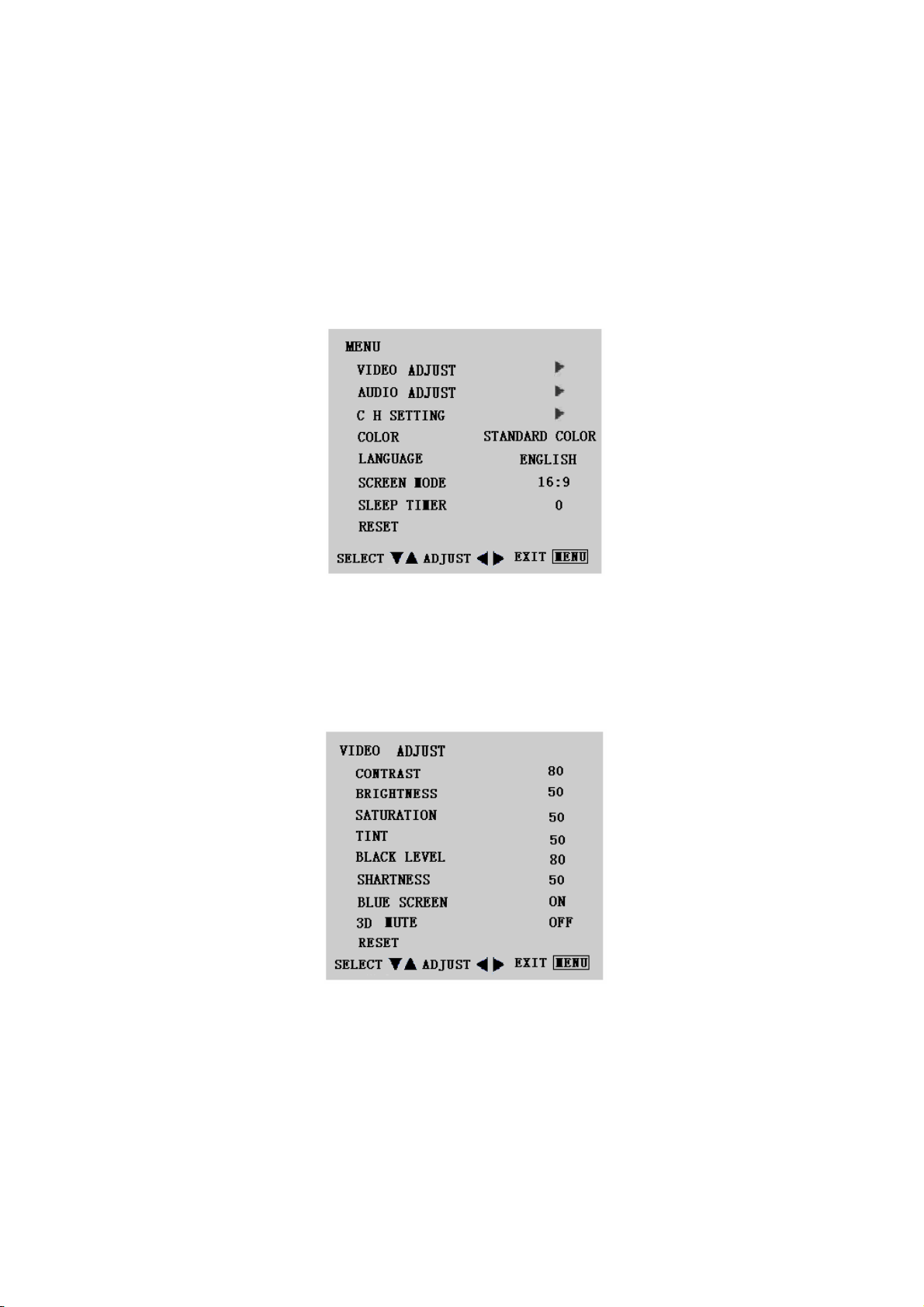
MAIN MENU
Press the MENU button into the main OSD (On Screen Display). Adjust item include VIDEO ADJUST, AUDIO
ADJUST, CH SETTING, COLOR, LANGUAGE, SCREEN MODE, SLEEP TIMER, RESET.
Video Adjust
1: Contrast, Brightness and Saturation are adjusted from 0 to 100.
2: TINT User can adjust the favorable tint while the TV system is NTSC,PAL system can’t support.The adjustment
range is 0 to 100.
3: Black Level is adjusted from 0 to 100.
4: Sharpness is adjusted from -5 to+5.
You can adjust picture contrast, brightness, saturation, tint, black level and sharpness to the levels you prefer.
5: Blue Screen for when no video input screen will be blue or blank. If it’s ON, the screen will be in blue. If it’s OFF,
the screen will be blank. Preset is ON.
6: 3D Mute When the signal is not well,user can start up the function.
7. Reset is set up to default value.
4
Page 6
TCL LCD32B67
When adjust any item sub-OSD will show up like this.
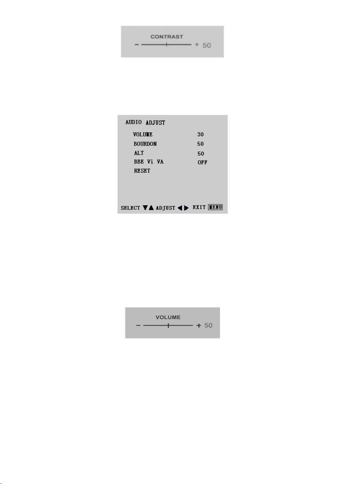
Audio Adjust
1. Volume is adjusted from 0 to 100.
2. Bourdon is is adjusted from 0 to 100.
3. Alt is adjusted from 0 to 100.
4. BBE Vi VA ON or OFF is for your alternative (when BBE is started , BOURDON and ALT can’t be adjusted).
5. RESET is set up to default value.
You can adjust picture Volume, Bass and Treble to the levels you prefer.
When adjust any item sub-OSD will show up like this.
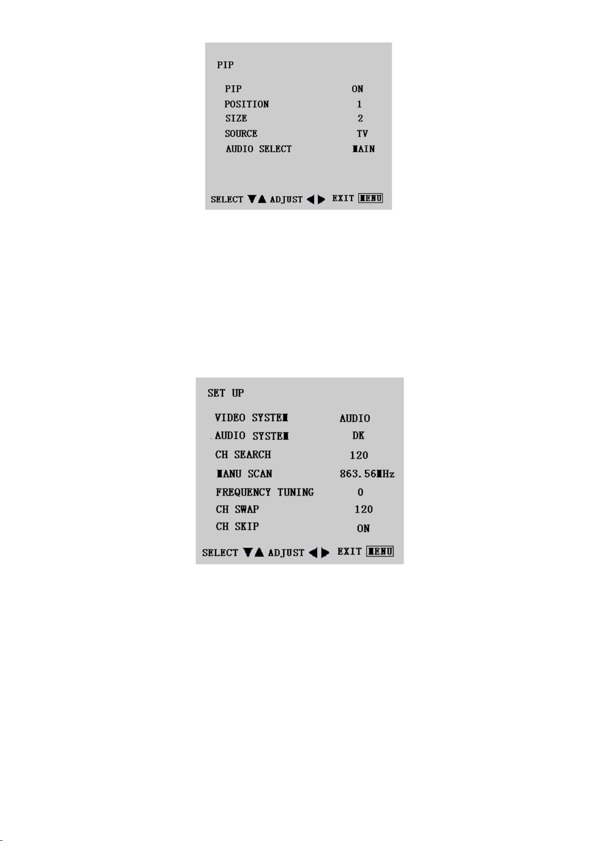
PIP
1. PIP function is turn on /off small picture
2. Position is move for small picture
3. SIZE big picture or small picture,which is for your choice
4. Source is choose from TV /AV1/AV2/S VIDEO
5. Audio select is choose from MAIN/SUB
5
Page 7
TCL LCD32B67
Sleep Timer is for set a time period after which the TV should switch itself to standby. The counter runs from 30 > 60
> 90 > 120 minutes.
The timer begins to count down from the number of minutes selected after the display has disappeared.
Note: To view the remaining time, press the SLEEP button once. To cancel the sleep time, repeatedly press the
SLEEP button until--- APPEARS. If you turn the TV off after setting the sleep time, the setting will be erased. Set it
again.
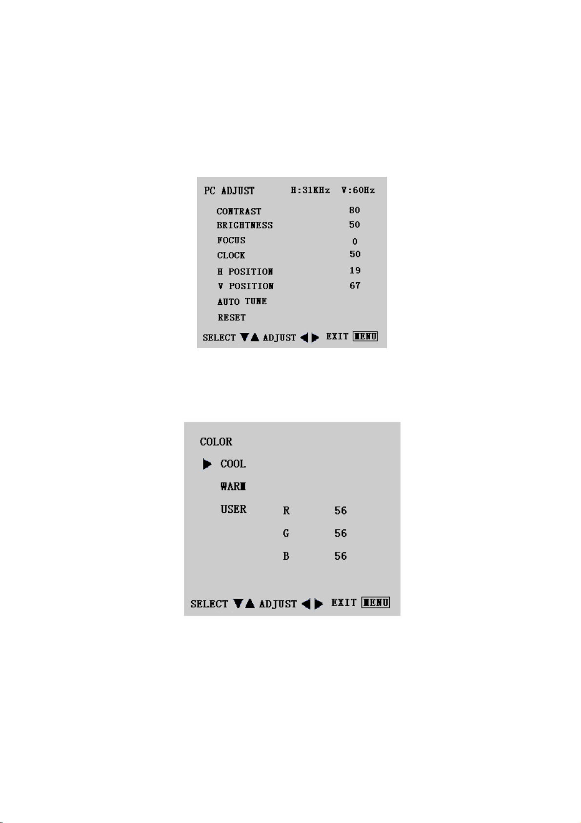
Set up
1. Video System is used for TV broadcasting system,AUTO/NTSC/PAL.
2. Audio System is used for the TV broadcasting audio system, DK system is widely used in China mainland.
3. CH SEARCH Is used for search all the TV programs and memorized them into the interior stock.
There are 120 channels in total for TV.If the remote control is pressed beyond 120 channels,the channel
will be returned back to the previous one automatically.
4.
Manu Scan for search TV Program channel by channel.
After scan a new program, press MENU key, it will be automatically saved in the last channel.
5.
Frequency tuning Tuning of the frequency for the channel so as to get the better effect.
6. CH SWAP save the location of current channel and destination channel for each other .
6
Page 8
TCL LCD32B67
7. CH SKIP if the setting is ON,the channel is shielded. Pressing the figure key will be entered
into;otherwise,pressing the program key(up and down) is useless.If the channel is to be resumed, it must be
set OFF.
PC Adjust
1. Auto tune is the function auto-sizing for VGA input.
2. Contrast, Brightness, Focus, Clock, H Position, V Position and Color are the functions for PC adjustment.
Color
for you can adjust the color temperature you prefer.
7
Page 9
TCL LCD32B67
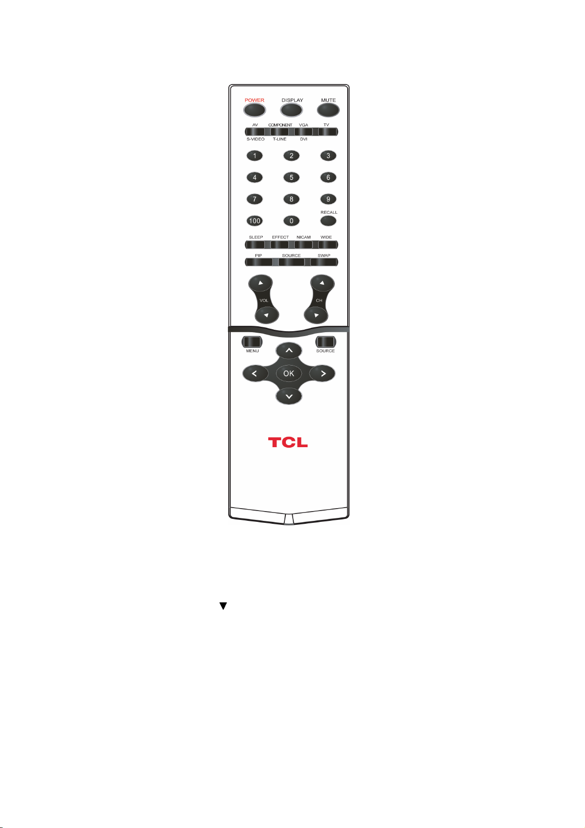
USE THE REMOTE CONTROL
POWER
Press to turn on/off the TV.
The TV is never completely
powered off unless it is
physically unplugged or or
turn off the power switch on
the side.
Video/S-Video
Select your input source to
VIDEO or S-VIDEO
Component/T-LINE
Select your input source to
Component or T-LINE
VGA/DVI
Select your input source to
VGA or DVI
.
TV
Select your input source to
TV
0~9/100 Digit buttons
To select a TV channel
SLEEP
With this key you can set a
time period after which the
TV should switch itself to
standby. Press the key
repeatedly to select the
number of minutes. The
counter runs from
0,15,30,45,60,90,120
minutes. The timer begins
to count down from the
number of minutes
selected after the display
has disappeared.
PIP
Select PIP on/off to display
PC and other sources at
the same time((This
function will be in effect
only during the VGA and
DVI input stage).
VOL
Press ▲or▼ to adjust the
volume.
CH
Press ▲ or ▼ to browse
through the TV channels
which are not erased.
MENU
Press repeatedly to display OSD menu.
SOURCE
Press this button to display selected source, press ▲
button to select.
OK
Press the button to confirm selection.
MENU Left/Right button
use this button to confirm selection or adjust the desired
parameter; otherwise, to increase/decrease the volume.
Menu Up/Down button
When in menu mode, use this button to select to the
up/down; otherwise, to change TV channels
DISPLAY
(1) Display Channel number
when use RF input.
(2) Display input source
when use other input
except TV RF input.
MUTE
Temporarily interrupt the
sound or restore it.
RECALL
To display the previously
selected TV channel.
EFFECT
You can choose your prefer
mode of User 、 STEREO 、
CINEMA、NEWS、DDAS、BBE
ViVA
NICAM
To select Mono /Stereo/Sound
A /Sound B/Sound AB from
TV RF input.
WIDE
Includes 3 modes: Press
repeatedly to select
4:3 /16:9 /
16:9 non-Linear
SWAP
Not support.
8
Page 10

TCL LCD32B67
1. Input Source Select:
Press repeatedly Source button to select TV, AV1, AV2, S-VIDEO, COMPONENT or PC mode.
2. Input Video Signal:
S-Video level 0.7Vpp: NTSC / PAL / SECAM
Composite Video level 0.7Vpp: NTSC / PAL / SECAM
Video signal termination impedance 75 Ohm
3. Scanning Frequencies:
Horizontal: 31.5 KHz ~ 48.36 KHz
Vertical: 60 Hz ~75 Hz
4. PC factory Preset Timing: 7
Follow VESA standard timing.
Input signal tolerance : H tolerance ± 1 K, V tolerance ±1 Hz
5. Power Source:
Switching Mode Power Supply
AC 100 ~ 240 V ± 5%, 50/60 ± 3Hz Universal Type
6. Operating Temperature: + 0°C ~ + 40°C
Storage Temperature: - 25°C ~ + 60°C
7.
Humidity:
Operating: 10% ± 85% RH
Storage : 5% ~ 85% RH
8. Weight for packed: 20.5 Kg
9. External Connection:
RF Input Connector, 15Pin D-type Connector, 24Pin DVI Connector , AC power-Cord
10. View Angle: 176°(Horizontal) / 176°(Vertical)
12. Plug and Play: VESA DDC2B
13. Power saving: VESA DPMS
1-2 LCD TV DESCRIPTION
The LCD TV will contain a main board (include audio), a switching power board, an IR board, a function
keyboard, a DPF Board and an Ear phone board. The main board and power board will house the flat panel to
control logic I2C bus, DDC, brightness control logic for LCD panel, DC-DC conversion to supply the
appropriate power to the whole board and transmitting TTL level signals into LCD Module to drive the LCD
display circuit.
The inverter board will drive the sixteen CCFLs (Cold Cathode Fluorescent Tube).The switching power
board will provides the power ON/OFF to control the TV and control LED indicator for DPMS.
The function keyboard and Remote Control will provide the OSD control signal to the Main Board.
9
Page 11

TCL LCD32B67
2. PRECAUTIONS AND NOTICES
2-1 ASSEMBLY PRECAUTION
Please do not press or scratch LCD panel surface with anything hard. And do not soil LCD panel surface by touching
with bare hands (Polarize film, surface of LCD panel is easy to be flawed)
In the LCD panel, the gap between two glass plates is kept perfectly even to maintain display characteristic and
reliability. If this panel is subject to hard pressing, the following occurs :
(a) Uniform color
(b) Orientation of liquid crystal becomes disorder
Please wipe out LCD panel surface with absorbent cotton or soft cloth in case of it being soiled.
Please wipe out drops of adhesive like saliva and water in LCD panel surface immediately.
They might damage to cause panel surface variation and color change.
Do not apply any strong mechanical shock to the LCD panel.
2-2 OPERATING PRECAUTION
Please be sure to unplug the power cord before remove the back-cover. (be sure the power is turn-off)
Please do not change variable resistance settings in MAIN-BOARD; they are adjusted to the most suitable value. If
they are changed, it might happen LUMINANCE does not satisfy the white balance spec.
Please consider that LCD backlight takes longer time to become stable of radiation characteristic in low temperature
than in room temperature.
Please pay attention to displaying the same pattern for very long-time. Image might stick on LCD.
2-3 STORAGE PRECAUTION
When you store LCD for a long time, it is recommended to keep the temperature between 0°C -40°C without the
exposure of sunlight and to keep the humidity less than 85% RH.
Please do not leave the LCD in the environment of high humidity and high temperature such as 60°C, 85%RH.
Please do not leave the LCD in the environment of low temperature; below -25°C.
2-4 HIGH VOLTAGE WARNING
The high voltage was only generated by INVERTER module on Power Board, if carelessly contacted the transformer
on this module, can cause a serious shock. (the lamp voltage after stable around 600V, with lamp current around 8mA,
and the lamp starting voltage was around 1500V, at Ta=25°C)
10
Page 12
TCL LCD32B67
3. INPUT/OUTPUT SPECIFICATION
3-1 CONNECTOR DESCRIPTION
1. This procedure gives you instructions for installing and using the LCD TV display.
the display on the desired operation and plug the power cord into a convenient AC outlet. Three-wire power cord
must be shielded and is provided as a safety precaution as it connects the chassis and cabinet to the electrical
conduct ground. If the AC outlet in your location does not have provisions for the grounded type plug, the installer
should attach the proper adapter to ensure a safe ground potential.
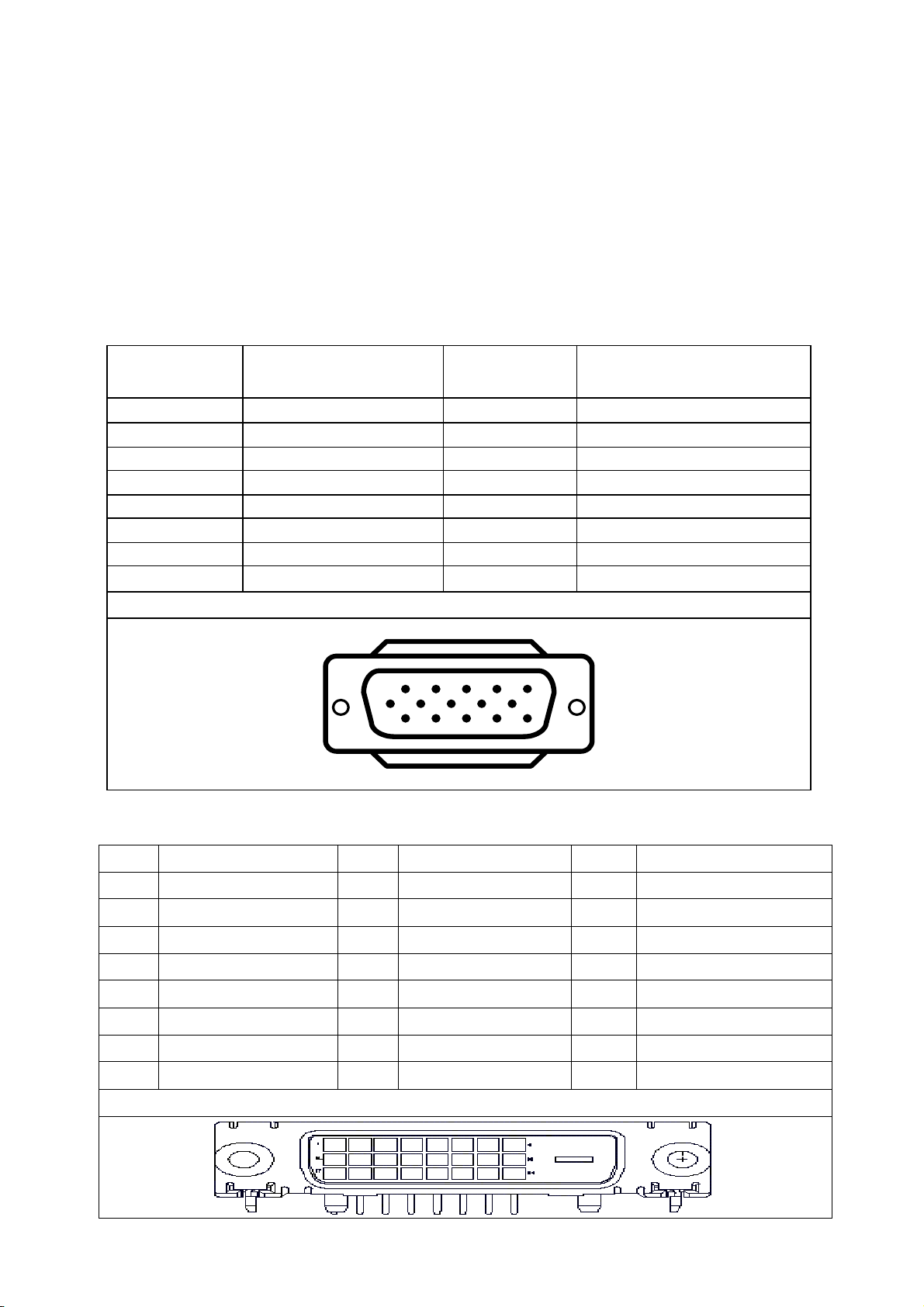
2. Connect the 15-pin color display shielded signal cable to your signal system device and lock both screws on the
connector to ensure firm grounding. The connector information is as follow:
D-SUB CONNECTOR
PIN NO. DESCRIPTION PIN NO. DESCRIPTION
1 Red Video 9 5V
2 Green Video 10 Sync Ground
3 Blue Video 11 Not Used
4 Not Used 12 Serial Data for DDC
5 Ground 13 H-Sync.
6 Red Ground 14 V-Sync.
7 Green Ground 15 Serial Clock for DDC
8 Blue Ground
15 - Pin Color Display Signal Cable
DVI CONNECTOR
Pin Meaning Pin Meaning Pin Meaning
1. TMDS Data 2- 9. TMDS Data1- 17. TMDS Data 0-
2. TMDS Data 2+ 10. TMDS Data1+ 18. TMDS Data 0+
3. TMDS Data 2 Shield 11. TMDS Data 1 Shield 19. TMDS Data 0 Shield
4. No Connect 12. No connect 20. No connect
5. No Connect 13. No connect 21. No connect
6. DDC clock 14. No connect 22. TMDS Colck Shield
7. DDC Data 15. Ground 23. TMDS Clock +
8. No Connect 16. Hot Plug Detect 24. TMDS Clock -
1
6
11 15
24 - Pin DVI Layout
5
10
3. S-Video ( Y /C ): TV rear side : 4 pin Mini-DIN female
11
Page 13
TCL LCD32B67
Component Video: TV rear side : RCA female ( Red / Blue / Green )
TV: TV rear side : IEC type female
AV1,AV2 : TV rear side : RCA female (Yellow )
Audio: TV rear side : RCA female (Red / White )
PC Input audio: 3.5mm Stereo female
Headphone 3.5mm female
HDMI TV rear side
RF TV rear side
Audio Input for AV1,AV2,S-Video, Component Video : RCA female ( Red / White )
Audio line Out ( to another speaker ) : RCA female ( Red / White )
4. Apply power to the display by turning the power switch to the "ON" position and allow about ten seconds for Panel
warm-up. The Power-On indicator lights "GREEN" when the display is on.
5. With proper signals feed to the display, a pattern or data should appear on the screen, adjust the brightness and
contrast to the most pleasing display, or press auto-adju to get the best picture-quality.
6. This TV (with PC function) has power saving function following the VESA DPMS. Be sure to connect the signal
cable to the PC.
7. If your TV requires service, it must be returned with the power cord.
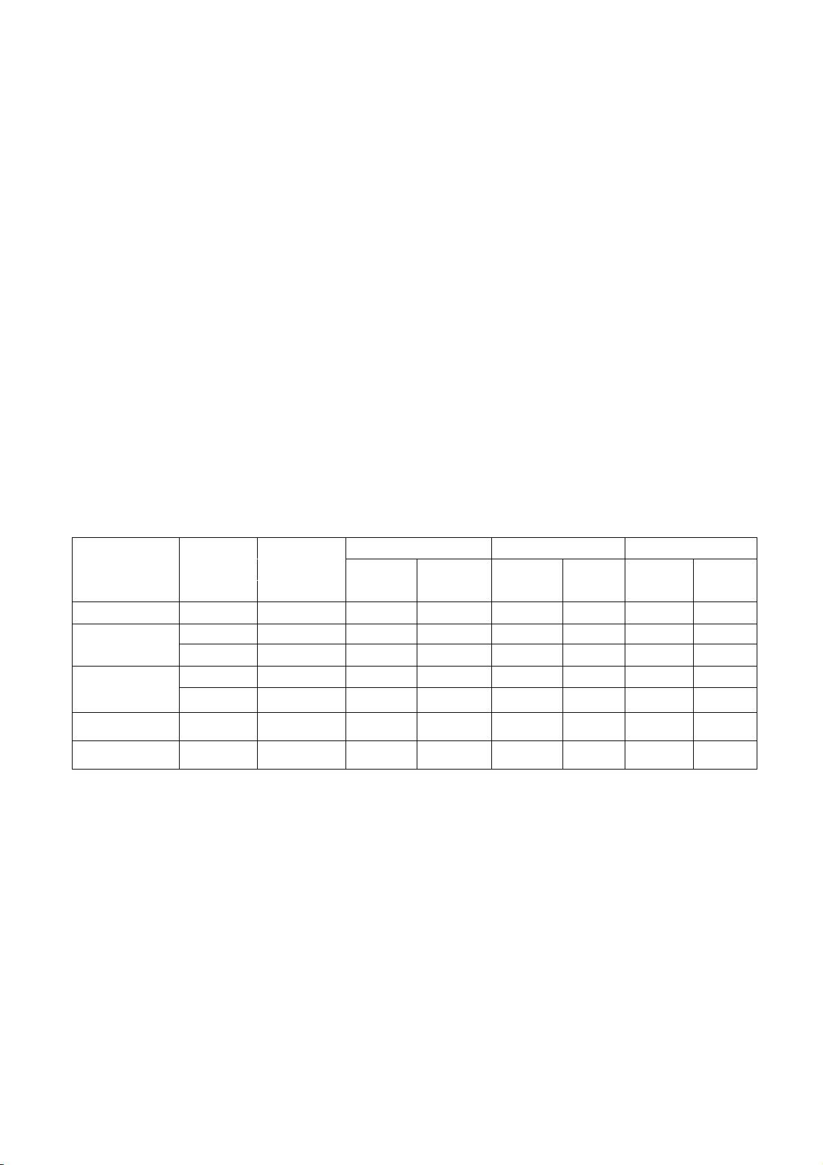
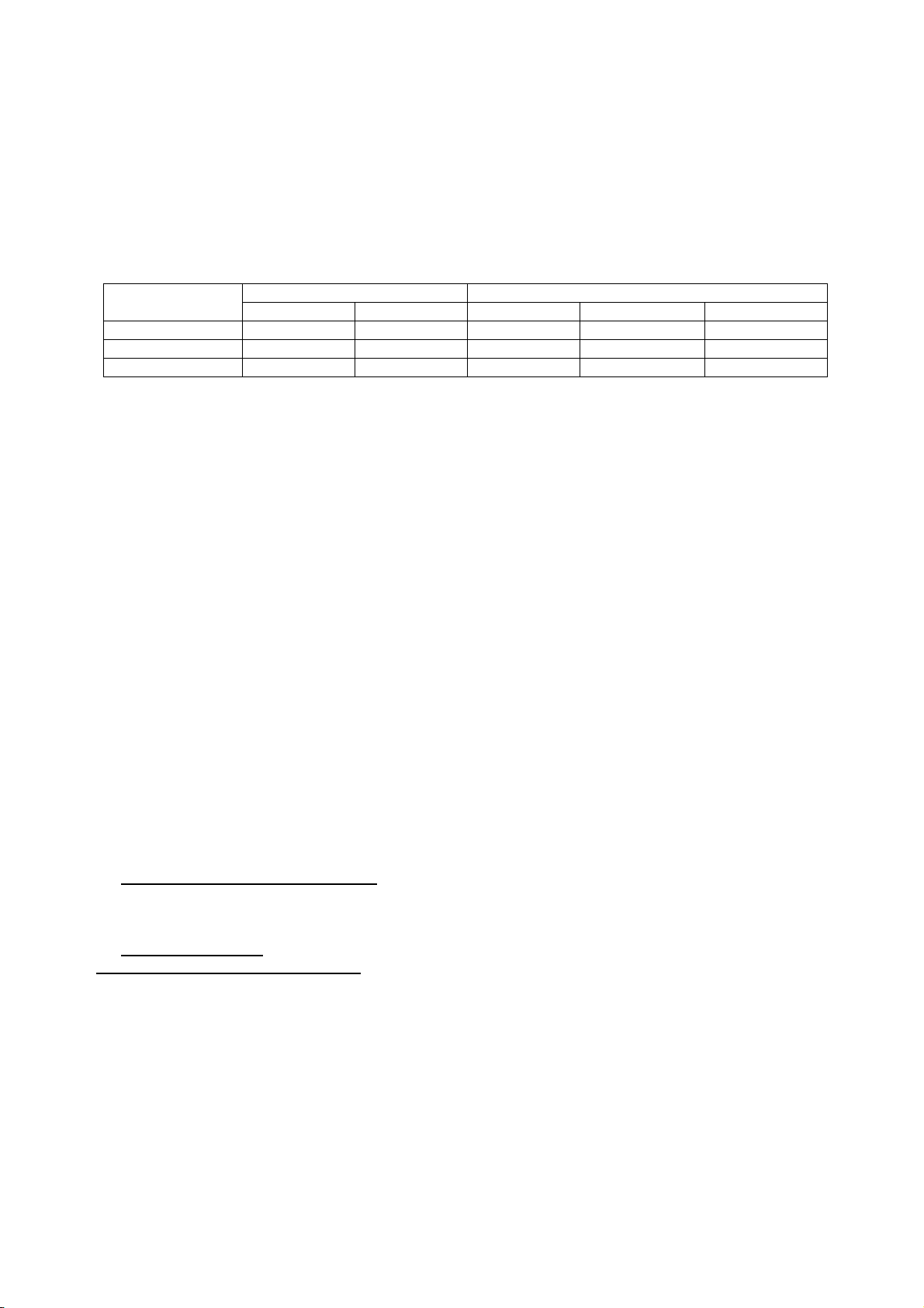
3-2 FACTORY PRESET DISPLAY MODES
Analog RGB Signal Timing
Vertical Horizontal Sync Polarity Presence Screen Mode
Dots × Lines
720 × 400
640 × 480
800 x 600
Frequency Frequency Horizontal Vertical Horizontal Vertical Normal FULL
(Hz) (kHz) (4:3) (16:9)
70.1 31.5 NEG POS YES YES YES NO
59.9 31.5 NEG NEG YES YES YES NO
75.0 37.5 NEG NEG YES YES YES NO
60.0 37.9 POS POS YES YES YES NO
75.0 46.87 POS POS YES YES YES NO
1024 x 768 60.0 48.36 NEG NEG YES YES YES NO
1280 x 720 60.0 44.77 NEG NEG YES YES NO YES
12
Page 14
TCL LCD32B67
4. ADJUSTMENT
4-1 ADJUSTMENT CONTROL FUNCTION
Adjustments items as below:
4-1.1 Power On / Off.
4-1.2 PC
Auto adjustment for Brightness, Contrast , Pixel Clock Frequency, Focus,
Picture H / V Position and Color Temperature.
Recall Cool, Warn and User color adjust for Color Temperature.
4-1.3 PIP
Position Select, Video source select, Audio main/sub Select.
4-1.4 TV
Channel Up / Down, Channel Search, Volume Bass / Treble adjusts.
Blue screen / Language / System / CH swap /Manual scan / CH Del Add
Reset.
4-1.5 Video
Brightness and Contrast adjust, Saturation adjust,
Sharpness and Black level adjust, Reset
4-2 ADJUSTMENT METHOD
Press MENU key to show OSD window or exit, Up / Down key to done the function selection,
And + / - key to done the adjustment.
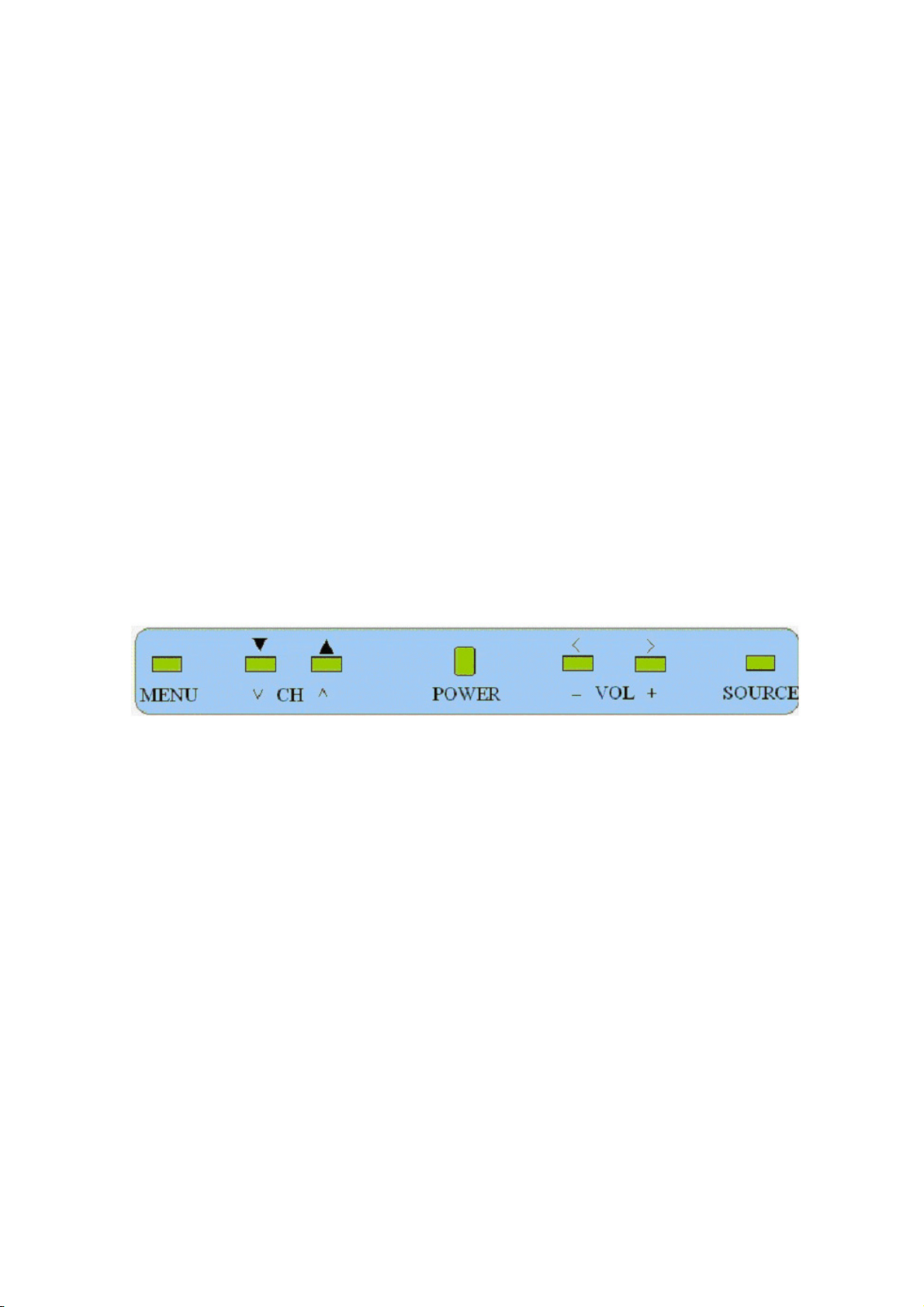
FRONT PANEL CONTROL KNOBS
Power Key:This switch shall be visible and accessible on the down right side of front PC frame. Soft Power Switch
(TURN ON SYSTEM) and one push of Soft-Power Switch shall turn on the system.
Power Indicator LED: This LED will illuminate “Green” light when the product is ON and “Orange” light when the
product in stand-by mode.
MENU Key:This switch shall be visible and accessible on the left side of VOL - switches. Once pressed, this key
shall bring up the corresponding OSD menu(s) based on the selected input source.
CH +/-:These two switches shall be visible and accessible on the bottom of front panel control keys. While TV is
selected as input source, activation of these keys will cycle through all available TV channels. While OSD
menu is up, activation of these keys will highlight each available adjustment. The activation time for this
switch includes Press and Hold should be less than half second.
VOL +/-:These two switches shall be visible and accessible on the bottom of front panel control keys. Activation will
increase /decrease loudness of the audio output. In addition, while OSD menu is up, activation of these
keys will regulate a pre-selected adjustment. The activation time for this switch includes Press and Hold
should be less than half second.Source Key:Press to select your input source.
Headphone: This connector is designed purpose to use headphone. Once the headphone connected, then the
speakers will auto mute on audio output.
SOURCE: This switch shall be visible and accessible on the right side of VOL + switches. Once pressed, this key
show the source can select.
13
Page 15
TCL LCD32B67
A
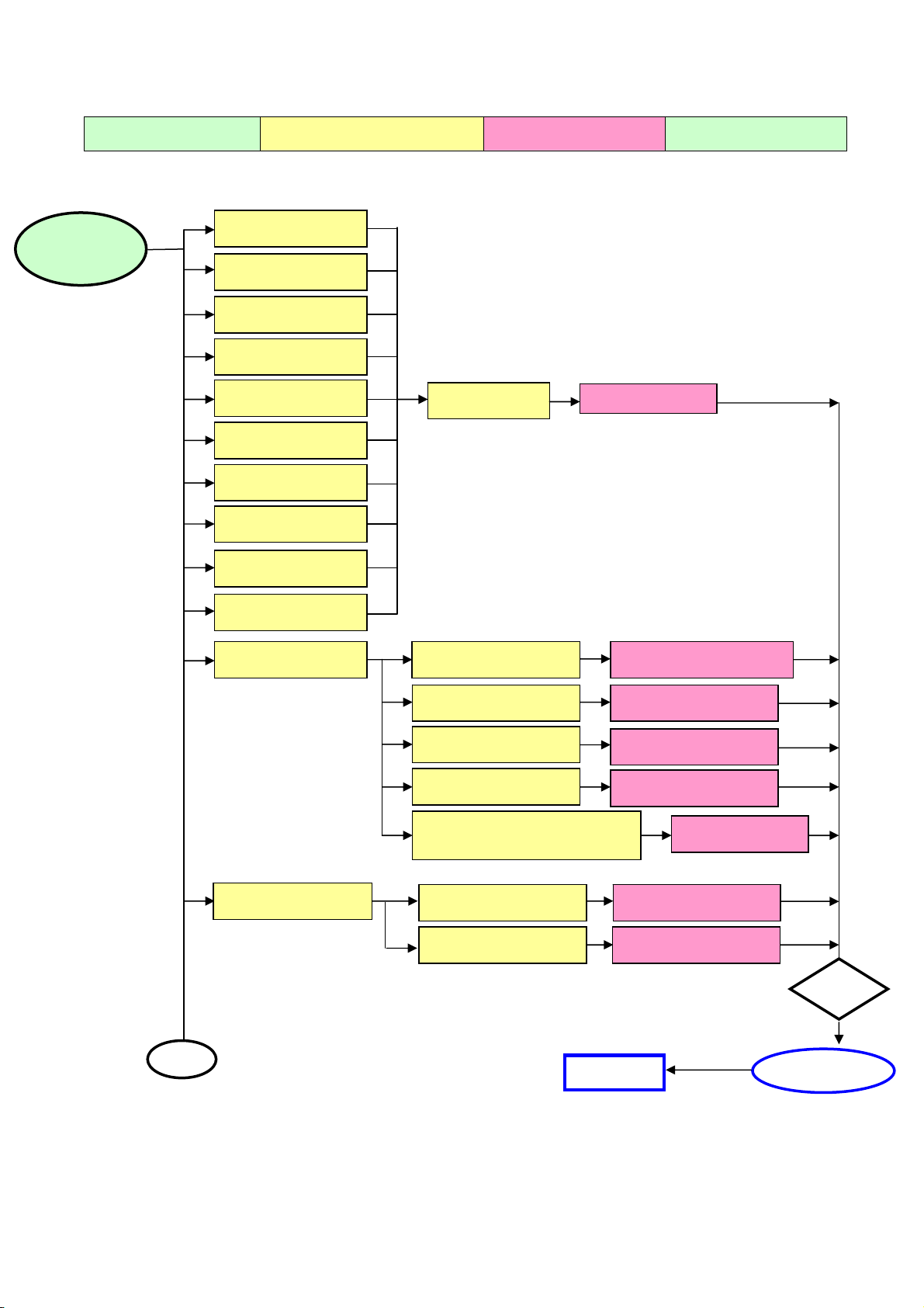
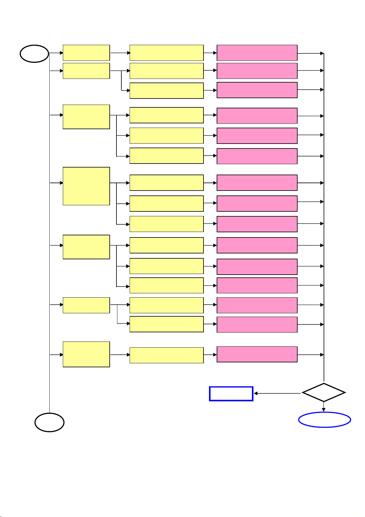
5. REPAIR FLOW CHART
Defect Mode Failure Analysis Repair Testing
Abnormal
Display
Missing Line
Bright Dot
Dark Dot
Light Leakage
Mura
Image Sticking
Dot Defect
Brightness Spot
Dot Defect
Particle
No display Check Power Board
Check Panel
Panel Change
Change Power Board
Check Main board
Check Panel
Check Keyboard
Check Line Connected
Power board and Minored
Noise
Check Main board
Check Panel
Change Main board
Change Panel
Change Keyboard
Change Main board
Change Panel
Next Step
Change Wires
Test
NG
Completed
14
Page 16
TCL LCD32B67
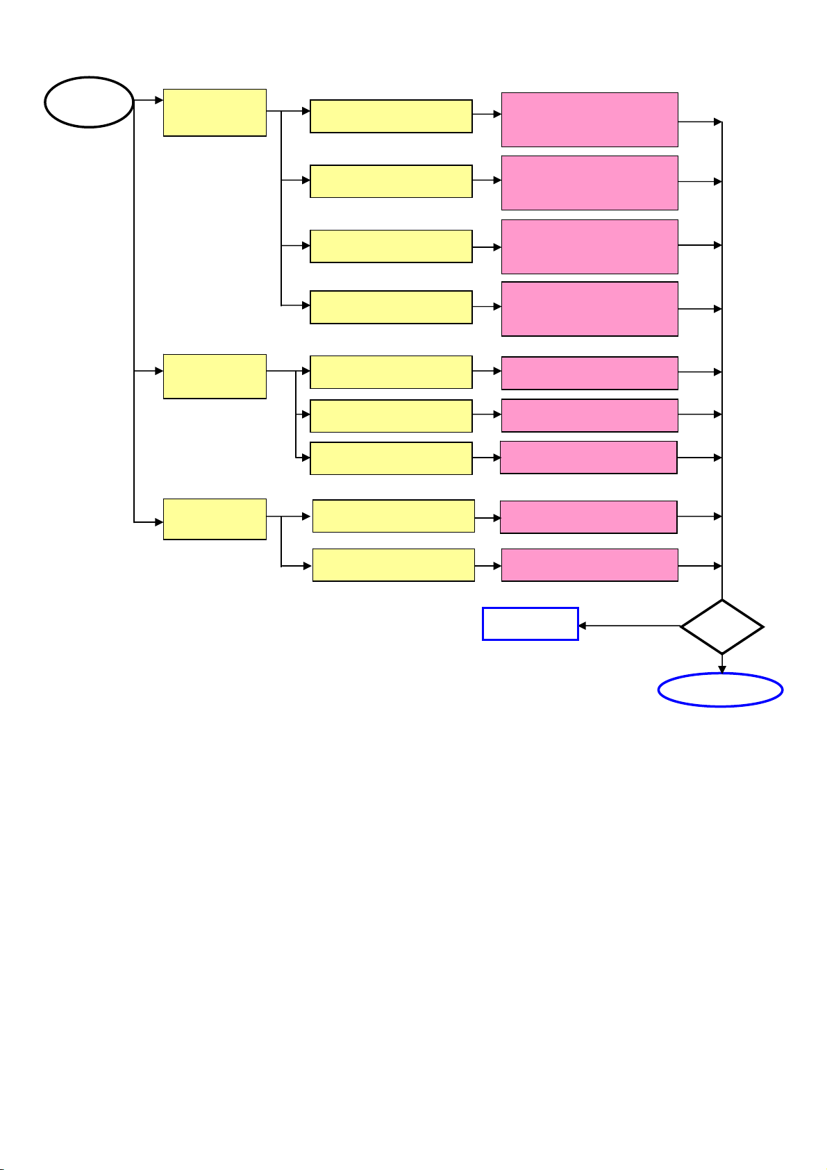
A
A
Noise Check Single Cable Change Single Cable
Flicker Check Main board Change Main board
Change Panel
Change Main board
Change Panel
Change LVDS Cable
Change Panel
Abnormal
Gray
R\G\B
Display
Abnormal
Check Panel
Check Main board
Check Panel
Check LVD Cable
Check Single Cable Change Single Cable
Check Main board Change Main board
Check Panel
Monitor
Shut Down
No signal Check Single Cable Change Single Cable
Power on
Display
bnormal
Check Power board Change Power board
Check Main board
Check Keyboard Change Keyboard
Check Main board
Check Main board
Change Main board
Change Main board
Change Main board
NEXT STEP
Test
A
15
Complete
Page 17
TCL LCD32B67
A
LED Display
Abnormal
Abnormal
Keyboard
LED Off
LED Dark
LED Abnormal
LED Flicker
Check Wires
Check Main board
Check Keyboard
Change Keyboard or
Main board or wire
Change Keyboard or
Main board
Change Keyboard or
Main board or wire
Change Keyboard or
Main board or wire
Change Wires
Change Main board
Change Keyboard
Abnormal
OSD
Check Main board
Check LVDS Wire
Change Main board
Change LVDS Wire
Next step
Test
COMPLETE
16
Page 18
TCL LCD32B67
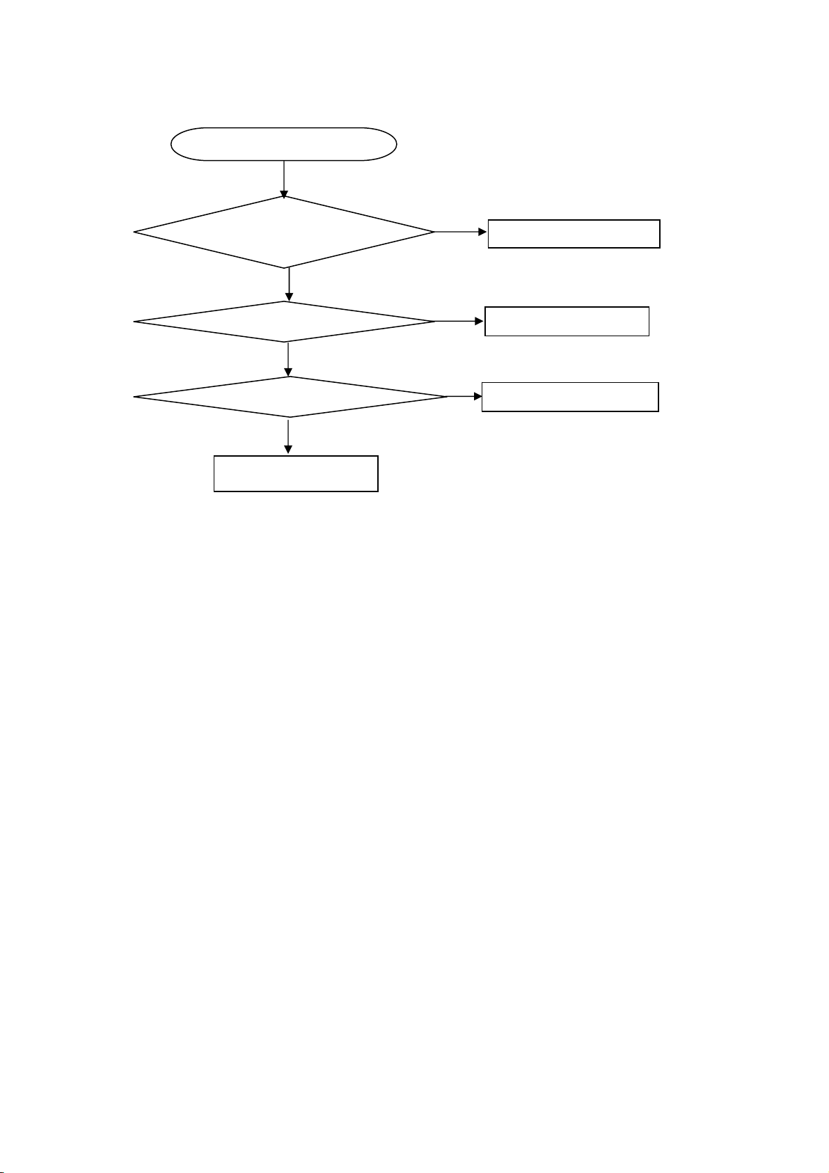
Key Board
OSD is unstable or not working
N
Is Key Pad Board connecting normally?
Y
Connect Key Pad Board
Is Button Switch normally?
Y
Is Key Pad Board Normally?
Y
Check Main Board
N
N
Replace Button Switch
Replace Key Pad Board
17
Page 19
TCL LCD32B67
6. WHITE-BALANCE, LUMINANCE ADJUSTMENT
Approximately 30 minutes should be allowed for warm up before proceeding white balance
adjustment.
Before started adjust white balance ,please setting the Chroma-7120 MEM. Channel 1 to 9300 color, MEM.
channel 2 to 6500 color, MEM. channel 3 to 11000 color,and MEM. channel 4 to 9300 color, ( our 9300 parameter
is x = 283 ± 20, y = 297 ± 20, Y = 350 ± 7 cd/m
11000 parameter is x = 274 ± 20, y = 286 ± 20, Y = 460 ± 7 cd/m2 ;9300 parameter is x = 283 ± 20, y = 297 ± 20, Y =
460 ± 7 cd/m
2
;7000 parameter is x = 305 ± 20, y = 320 ± 20, Y = 460 ± 7 cd/m2 )
Color Temp.
X 0.283 0.313 0.274 0.283 0.305
Y 0.297 0.329 0.286 0.297 0.320
Y 350 350 460 460 460
PC Mode AV Mode
9300 6500 11000 9300 7000
How to setting MEM.channel you can reference to Chroma-7120 user guide or simple use “ SC” key and “ NEXT” key
to modify x,y,Y value and use “ID” key to modify the TEXT description
Following is the procedure to do white-balance adjust
․Press Number key 100 Æ 9 Æ 9 Æ 9 will into the factory mode, and press Menu key the OSD will show menu and a
word F at Right top of Menu.
․In the factory mode select MORE function will into Bias and Gain adjustment.
1. ADC Adjustment:
AL Æ Auto level adjust.
RG, GG, BG Æ R, G, B Gain adjust.
RB, GB, BB Æ R, G, B Bias adjust.
2. SCALER Adjustment:
CO, BR Æ Contrast and Brightness adjust.
RG, GG, BG Æ R, G, B Gain adjust.
RB, GB, BB Æ R, G, B Bias adjust.
S9, S6, ST , SH Æ Save 9300, 6500, 9300 color temperature.
R9, R6, RT , RHÆ Recall 9300, 6500, 9300 color temperature.
BI Æ Setup Burn-in mode ON / OFF .
ISP ÆSet ISP ON/OFF .
PP Æ Set PIP ON/OFF .
WH Æ Set Wireless Headphone ON/OFF .
SR Æ Set SRS ON/OFF.
CC Æ Set Close Caption ON/OFF.
VC Æ Set V Chip ON/OFF.
EX Æ Exit MORE function to factory mode menu.
II. Bias (Low luminance) adjustment :
1. Press “ AUTO” button ,
2. Set the contrast on OSD window to the value=51 , color (user )R,G,B set to “50”
3. adjust the brightness on OSD until chroma 7120 measurement reach the value Y>390 cd/m
III. Gain adjustment :
A. Adjust 9300 color-temperature :
1. Set the Contrast of OSD function to 45 and Adjust Brightness to chroma-7120 Y>390 cd/m
2. Switch the chroma-7120 to RGB-mode (with press “MODE” button )
3. Switch the MEM.channel to Channel 01 ( with up or down arrow on chroma-7120 )
4. The lcd-indicator on chroma-7120 will show x = 283 ± 20, y = 297 ±20, Y = 350 ± 7 cd/m
5. Adjust the Color(user)Mode: RED on OSD window, until chroma 7120 indicator reached the value R=100
6. Adjust the Color (user) Mode: GREEN on OSD window, until chroma-7120 indicator reached the value
G=100
7. Adjust the Color (user) Mode: BLUE on OSD window, until chroma-7120 indicator reached the value B=100
8. Repeat above procedure (Item 5,6,7) until chroma-7120 RGB value meet the tolerance =100±2
9. switch the chroma-7120 to xyY mode With press “MODE” button
10. Press Color (9300) on OSD window to save the adjustment result
2
; 6500 parameter is x = 313 ± 20, y = 329 ± 20, Y = 350± 7 cd/m
2
2
2
2 ;
18
Page 20

TCL LCD32B67
B. Adjust 6500 color-temperature :
1. Set the Contrast of OSD function to 45 and Adjust Brightness to chroma-7120 Y>390 cd/m
2. Switch the chroma-7120 to RGB-mode (with press “MODE” button )
3. switch the MEM.channel to Channel 02 ( with up or down arrow on chroma-7120 )
4. The lcd-indicator on chroma-7120 will show x = 313 ± 20 y = 329 ± 20, Y = 350 ± 7 cd/m
5. Adjust the Color(user)Mode: RED on OSD window, until chroma 7120 indicator reached the value R=100
6. Adjust the Color(user)Mode: GREEN on OSD window, until chroma-7120 indicator reached the value G=100
7. Adjust the Color(user)Mode: BLUE on OSD window, until chroma-7120 indicator reached the value B=100
8. Repeat above procedure ( item 5,6,7) until chroma-7120 RGB value meet the tolerance =100 ± 2
9. switch the chroma-7120 to xyY mode With press “MODE” button
10. Press Color(6500) on OSD window to save the adjustment result
C. Adjust 11000 color-temperature:
1. Set the Contrast of OSD function to 45 and Adjust Brightness to chroma-7120 Y>390 cd/m
2. Switch the chroma-7120 to AV-mode (with press “MODE” button )
3. Switch the MEM.channel to Channel 03 ( with up or down arrow on chroma-7120 )
4. The lcd-indicator on chroma-7120 will show x = 274± 20, y = 286 ± 20, Y = 460 ± 7 cd/m
5. Adjust the Color(user)Mode: RED on OSD window, until chroma 7120 indicator reached the value R=100
6. Adjust the Color(user)Mode: GREEN on OSD window, until chroma-7120 indicator reached the value G=100
7. Adjust the Color(user)Mode: BLUE on OSD window, until chroma-7120 indicator reached the value B=100
8. Repeat above procedure ( item 5,6,7) until chroma-7120 RGB value meet the tolerance =100 ± 2
9. Switch the chroma-7120 to xyY mode With press “MODE” button
10. Press Color (11000) on OSD window to save the adjustment result
D. Adjust 9300 color-temperature:
1. Set the Contrast of OSD function to 45 and Adjust Brightness to chroma-7120 Y>390 cd/m
2. Switch the chroma-7120 to AV-mode (with press “MODE” button )
3. Switch the MEM.channel to Channel 04 ( with up or down arrow on chroma-7120 )
4. The lcd-indicator on chroma-7120 will show x = 283 ± 20, y = 297 ± 20, Y = 460 ± 7 cd/m
5. Adjust the Color(user)Mode: RED on OSD window, until chroma 7120 indicator reached the value R=100
6. Adjust the Color(user)Mode: GREEN on OSD window, until chroma-7120 indicator reached the value G=100
7. Adjust the Color(user)Mode: BLUE on OSD window, until chroma-7120 indicator reached the value B=100
8. Repeat above procedure ( item 5,6,7) until chroma-7120 RGB value meet the tolerance =100 ± 2
9. Switch the chroma-7120 to xyY mode With press “MODE” button
10. Press Color (9300) on OSD window to save the adjustment result
E. Adjust 7000 color-temperature:
1. Set the Contrast of OSD function to 45 and Adjust Brightness to chroma-7120 Y>470 cd/m
2. Switch the chroma-7120 to AV-mode (with press “MODE” button )
3. Switch the MEM.channel to Channel 05 ( with up or down arrow on chroma-7120 )
4. The lcd-indicator on chroma-7120 will show x = 305 ± 20, y = 320 ± 20, Y = 460 ± 7 cd/m
5. Adjust the Color(user)Mode: RED on OSD window, until chroma 7120 indicator reached the value R=100
6. Adjust the Color(user)Mode: GREEN on OSD window, until chroma-7120 indicator reached the value G=100
7. Adjust the Color(user)Mode: BLUE on OSD window, until chroma-7120 indicator reached the value B=100
8. Repeat above procedure ( item 5,6,7) until chroma-7120 RGB value meet the tolerance =100 ± 2
9. Switch the chroma-7120 to xyY mode With press “MODE” button
10. Press Color (7000) on OSD window to save the adjustment result
Turn the POWER-button off to on to quit from factory mode ( in USER-mode, the OSD window location was
placed at middle of screen)
2
2
2
2
2
2
2
2
19
Page 21
TCL LCD32B67
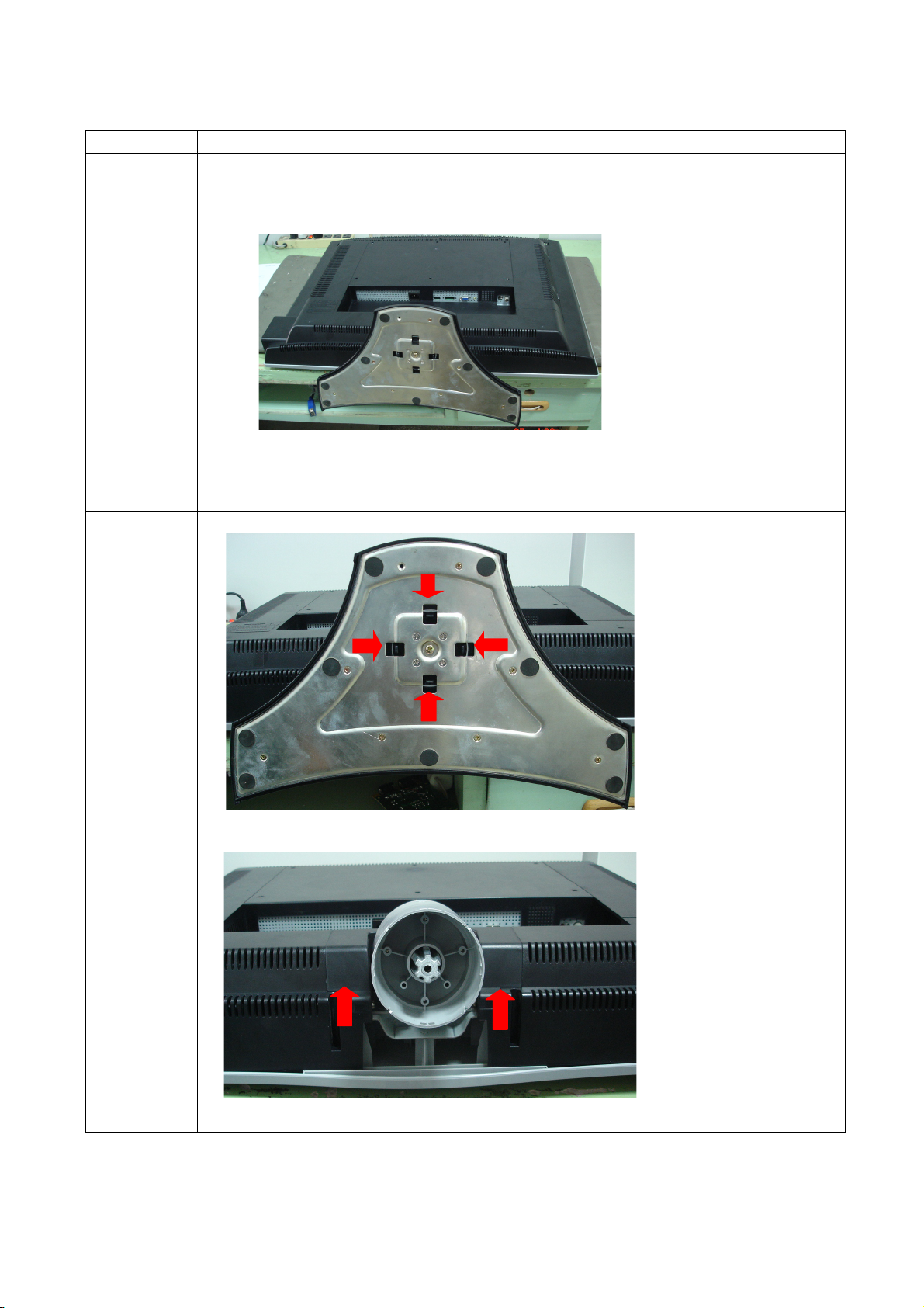
7. MECHANICAL INSTRUCTIONS
Step Figure Description
Lay the LCD-TV on a
Preparation
flat, soft and clean
surface.
Remove
the base
Remove
the hinge
cover
Push the clip for base
as the arrowheads.
Remove the hinge
cover as the
arrowheads and the
position by hand.
20
Page 22
TCL LCD32B67
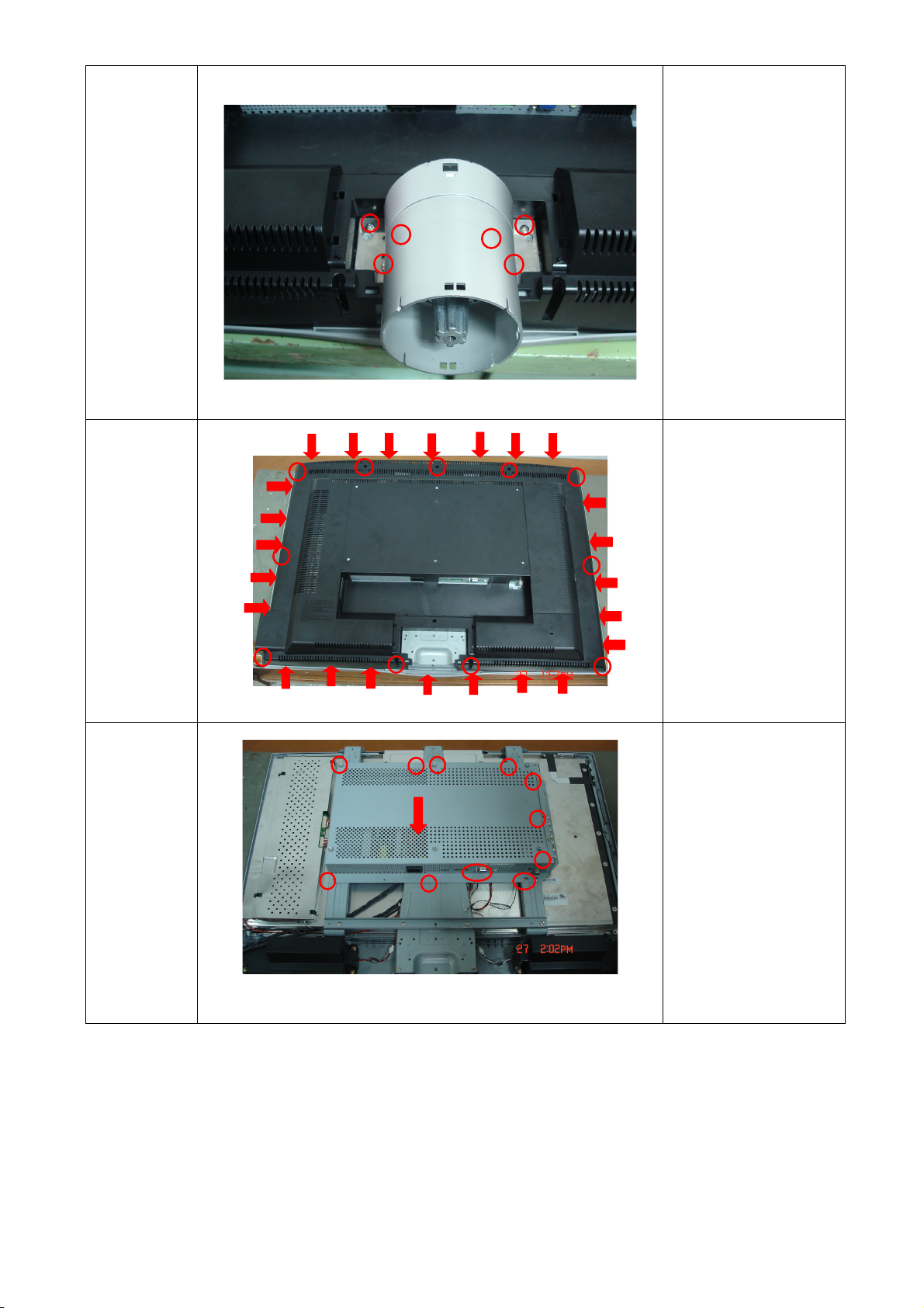
Remove
the stand
Remove
the back
cover
Remove the four
screws to remove
stand.
1. Remove the five
screws.
2. Remove the back
cover as the
arrowheads.
Remarks:
The arrowheads is the
position of the clips.
Remove
the shield
1. Remove the
thirteen screws
2. Push the shield as
the arrowhead
direction.
21
Page 23
TCL LCD32B67
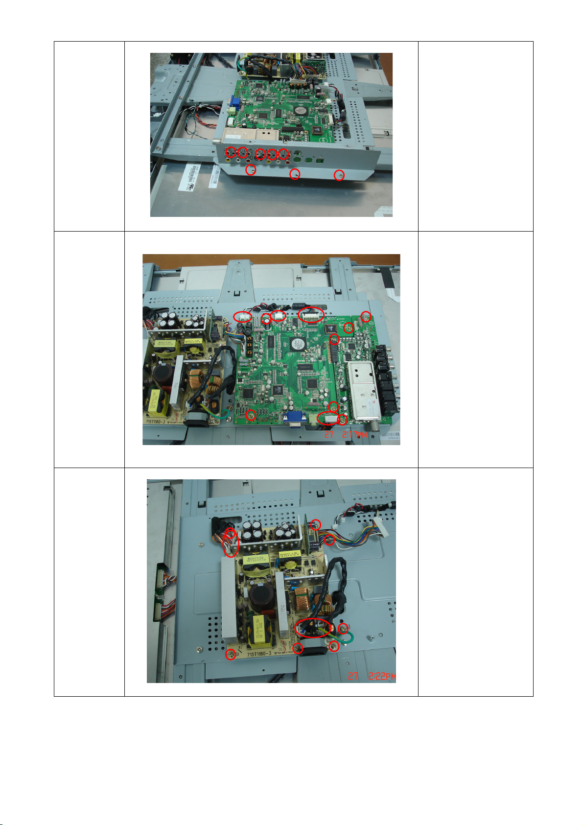
Remove
the tuner
cover
Remove
main and
tuner board
Remove the eight
screws
1. Remove the seven
screws
2. Disconnect the
connector
Remove
the power
board
1.Remove the seven
screws
2.Disconnect the
connector
22
Page 24
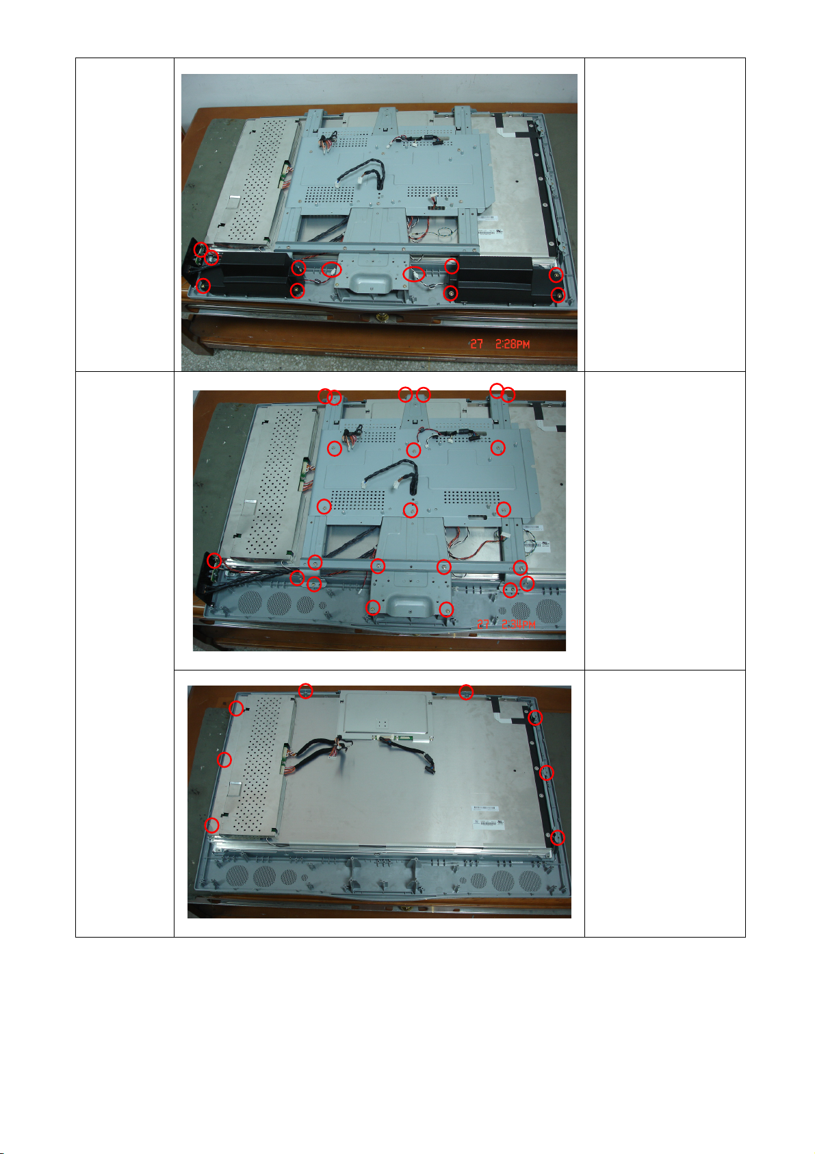
TCL LCD32B67
1. Remove the total
eight screws and
the two connectors
Remove
the
speakers
to remove speakers
2. Remove the three
screws to remove
key board
Remove
the iron
piece and
the AC
switch
Remove
the bezel
Remove the total
twenty-three screws to
remove the iron piece
and AC switch
Remove the eight
screws
23
Page 25

TCL LCD32B67
The end
Remark:
(PLS be careful, not to
scart the panel )
8. SOFTWARE FLOW CHART
24
Page 26

TCL LCD32B67
25
Page 27

TCL LCD32B67
26
Page 28

TCL LCD32B67
9. PARTS LIST OF CABINET
EJF5MSNDC2TLTM BOM
Location Part Number Description Quantity Unit
45T 76 28V19 PE BAG FOR SPK-LINK-MET 1 PCS
M1T 330 4128 SCREW 1 PCS
M1T 330 4128 SCREW 4 PCS
M1T 940 6120 SCREW 3 PCS
M1T 940 6120 SCREW 6 PCS
Q1T 340 10128 SCREW 1 PCS
ADPF24180A5 A/D+D/D POWER 1 PCS
CBPFJF5DMSTLT CONVESIN BOARD 1 PCS
TUPFFA3 TUNER BOARD 1 PCS
1T6020 1 SCREW-SPE CIAL 1 PCS
11TP004 1 CLIP WIRE DIA 10.9 2 PCS
15T5908 2 BRACKET 1 PCS
15T6189 1 CMO'PANEL SHIELD 1 PCS
15T8214 1 BKT MAIN 1 PCS
15T8215 1 BKT LSIDE 1 PCS
15T8216 1 BKT R SIDE 1 PCS
15T8217 1 BKT LONG 1 PCS
15T8220 1 BKT HOLD PANEL 1 PCS
15T8221 1 BKT HOLD PANEL 2 PCS
15T8221 2 BKT HOLD PANEL 4 PCS
15T8223 6 BKT CONNECTOR 1 PCS
15T8270 2 BKT-PCB-SUPPORT-1 1 PCS
34T1661 GM L COVER CABLE 1 PCS
34T1665 GM L COVER HINGE 1 PCS
34T1666 GM L COVER HINGE BOTTOM 1 PCS
44T3A08 1 EPS 1 PCS
44T3A08 2 EPS 1 PCS
44T3A08 3 EPS 1 PCS
44T3A08 4 EPS 1 PCS
44T3A08624 1A CARTON 1 PCS
45T 99606 2 PE BAG FOR MONITOR 1 PCS
45T 99609 2 EPE COVER 1 PCS
45T 99609 5 EPE COVER FOR BASE 1 PCS
45T 99626 2 PE BAG FOR MONITOR 1 PCS
50T 500 1 CABLE TIE 1 PCS
52T 1186 SMALL TAPE 10 CM
52T 1211 A ADHESIVE TYPE 2 PCS
85T 717 2 SHELD MAIN-2 1 PCS
89T 173 56 5 AUDIO CABLE 1 PCS
89T1738GAA D1 SIGNAL CABLE 1 PCS
89T414A18N YH POWER CABLE 1 PCS
92VB1JX1A21GM PEONY A1KALINE LR6(5#)E 2 PCS
95T8014 2 11 HARNESS 1 PCS
95T8014 3 16 HARNESS 1 PCS
95T8014 10 11 WIRE HARNESS 1 PCS
95T8014 12 13 WIRE HARNESS 1 PCS
95T8018 30 79 HARNESS 1 PCS
98TR7SW4NCTLF REMOTE CONTROL 1 PCS
27
Page 29

TCL LCD32B67
M1T 330 4128 SCREW 8 PCS
M1T 340 6 47 SCREW 6 PCS
M1T 940 6120 SCREW 6 PCS
M1T 940 6120 SCREW 7 PCS
M1T 940 6120 SCREW 6 PCS
M1T 940 6120 SCREW 4 PCS
M1T1140 6128 SCREW 4X6 1 PCS
M1T1730 6128 SCREW M3X6 12 PCS
Q1T 330 6128 SCREW 1 PCS
Q1T 340 10 47 SCREW 8 PCS
Q1T 340 10128 SCREW 1 PCS
Q1T 340 10128 SCREW 6 PCS
Q1T 340 10128 SCREW 9 PCS
Q1T 340 10128 SCREW 1 PCS
Q1T 930 6128 SCREW T3X6 2 PCS
705LJF5FB34007 BACK COVER ASS'Y 1 PCS
750VVMN0 B1 21 CMO 32" C3 PANEL 1 PCS
E095A 95T8014 5545 D HARNESS 1 PCS
E095B 95T8014 8576 D HARNESS 1 PCS
ADPF24180A5
AD24180A5SMT A/D+D/D POWER 1 PCS
DCPF1205A3 DC TO DC BOARD 1 PCS
40T 45762420A S/N LABEL 1 PCS
705L F94 56 01 IC981 ASS'Y 1 PCS
705L F94 57 02 Q942/Q943/D927/D928 ASS 1 PCS
705L F94 57 04 Q901/Q941/D902 ASS'Y 1 PCS
705L F94 87 01 CN901 ASS'Y 1 PCS
705L F94 93 01 BD901 ASS'Y 1 PCS
C901 63T 10722410S 0.22UF 250VAC ARCO 1 PCS
C903 65T306M1022BM Y1.CAP.001UF 250VAC MUR 1 PCS
C904 65T306M1022BM Y1.CAP.001UF 250VAC MUR 1 PCS
C905 63T213J105GFA MPF CAP 1 PCS
C907 67T 40K18116K 105C EC SHAP-IN 1 PCS
C915 65T306M1022BM Y1.CAP.001UF 250VAC MUR 1 PCS
C921 65T 1M103 3T6921 0.01uf 20% 1000V Y5V 1 PCS
C922 65T 1K222 2A6213 0.0022UF/1KV 1 PCS
C926 64T400K473 57 MPF CAP 1 PCS
C930 67T215L102 6N KY35VB1000M-L 5*25MM 1 PCS
C931 67T215L221 6N KY35VB220M-L 8*15MM 1 PCS
C932 67T215L1024NL KY25VB1000M-L 10*25MM 1 PCS
C933 67T215L1024NL KY25VB1000M-L 10*25MM 1 PCS
C934 67T215L221 4R LOWE.S.R 220UFM 25V 1 PCS
C942 65T 1K222 2A6213 0.0022UF/1KV 1 PCS
C948 67T215L102 6N KY35VB1000M-L 5*25MM 1 PCS
C949 67T215L102 6N KY35VB1000M-L 5*25MM 1 PCS
C950 67T215L102 6N KY35VB1000M-L 5*25MM 1 PCS
C951 67T215L102 6N KY35VB1000M-L 5*25MM 1 PCS
C955 67T215L471 6N KY35VB470M-L 10*20MM 1 PCS
C970 65T306M2222BP Y1.CAP.0022UF 250V AC 1 PCS
CN903 33T8029 3A WAFER 2P 3.96MM 1 PCS
CN904 33T8029 3A WAFER 2P 3.96MM 1 PCS
CN921 95T8013 12633 HARNESS 1 PCS
28
Page 30

TCL LCD32B67
CN951 33T3802 10 PLUG 1 PCS
CN952 33T3802 12 WAFER PH-12 1 PCS
D920 93T1100 1052T DIODE 1 PCS
D921 93T1100 1052T DIODE 1 PCS
D922 93V1020 752T UF4003 DO-41 1 PCS
D941 93T1100 1052T DIODE 1 PCS
D942 93T1100 1052T DIODE 1 PCS
D943 93V1020 752T UF4003 DO-41 1 PCS
IC922 56T 139 3A PC123Y22FZOF 1 PCS
IC924 56T 139 3A PC123Y22FZOF 1 PCS
IC925 56T 139 3A PC123Y22FZOF 1 PCS
IC942 56T 139 3A PC123Y22FZOF 1 PCS
L901 73L 253156 LG CHOKE COIL 1 PCS
L902 73L 253156 LG CHOKE COIL 1 PCS
L903 73T 174 68 L LINE FILTER 1 PCS
L904 73L 174 49 LG LINE FILTER 1 PCS
L905 73L 174 52LSG CHOKE COIL 1 PCS
L906 73L 174 44 TG CHOKE COIL 1 PCS
L922 73T 253155 L CHOKE 1 PCS
L923 73T 253155 L CHOKE 1 PCS
L952 73L 174 47LSG LINE FILTER 1 PCS
L953 73L 174 46LSG FILTER 1 PCS
R905 61T153M27858G6267 0.27 OHM 5% 3W 1 PCS
R919 61T153M27858G6267 0.27 OHM 5% 3W 1 PCS
R921 61T152M10458G6267 100K OHM 5% 2W 1 PCS
R945 61T153M47358G6267 47K OHM 5% 3W 1 PCS
R950 61T 20K398GB1 CEMENTR 0.39 OHM +-10% 1 PCS
RJ905 95T 90 26 WIRE HARNESS 1 PCS
T921 80LL26T 3 TG XFMR 1 PCS
T951 80LL26T 2 TG X'FMR 1 PCS
AD24180A5AI A/D+D/D POWER 1 PCS
C910 65T0805104 32 CHIP 0.1U 50V X7R 1 PCS
C911 65T0805102 32 CHIP 1000P 50VX7R 0805 1 PCS
C912 65T0805474 22 CHIP 0.47UF 25V X7R 1 PCS
C913 65T0805103 32 10NF/50V/0805/X7R 1 PCS
C914 65T0805104 32 CHIP 0.1U 50V X7R 1 PCS
C920 65T0805104 32 CHIP 0.1U 50V X7R 1 PCS
C924 65T0805104 32 CHIP 0.1U 50V X7R 1 PCS
C927 65T0805102 32 CHIP 1000P 50VX7R 0805 1 PCS
C935 65T0805104 32 CHIP 0.1U 50V X7R 1 PCS
C936 65T0805103 32 10NF/50V/0805/X7R 1 PCS
C937 65T0805104 32 CHIP 0.1U 50V X7R 1 PCS
C938 65T0805104 32 CHIP 0.1U 50V X7R 1 PCS
C939 65T0805104 32 CHIP 0.1U 50V X7R 1 PCS
C946 65T0805471 31 CHIP 470PF 50V NPO 1 PCS
C953 65T0805104 32 CHIP 0.1U 50V X7R 1 PCS
C956 65T0805104 32 CHIP 0.1U 50V X7R 1 PCS
C958 65T0805471 31 CHIP 470PF 50V NPO 1 PCS
C959 65T0805334 22 0.33UF+-10% 25V X7R 080 1 PCS
C964 65T1206103B2M6784 CHIP 0.01UF 630V X7R 1 PCS
C965 65T0805104 32 CHIP 0.1U 50V X7R 1 PCS
D901 93T3060 10 3A 600V 1 PCS
29
Page 31

TCL LCD32B67
D904 93T 6432V LL4148-GSO8 SMD BY VISH 1 PCS
D905 93T 6432V LL4148-GSO8 SMD BY VISH 1 PCS
D906 93T 6432V LL4148-GSO8 SMD BY VISH 1 PCS
D907 93T 6432V LL4148-GSO8 SMD BY VISH 1 PCS
D923 93T 6432V LL4148-GSO8 SMD BY VISH 1 PCS
D924 93T 6432V LL4148-GSO8 SMD BY VISH 1 PCS
D925 93T 6432V LL4148-GSO8 SMD BY VISH 1 PCS
D926 93T 6432V LL4148-GSO8 SMD BY VISH 1 PCS
D929 93T 6432V LL4148-GSO8 SMD BY VISH 1 PCS
D944 93T 6432V LL4148-GSO8 SMD BY VISH 1 PCS
D945 93T 6432V LL4148-GSO8 SMD BY VISH 1 PCS
D946 93T 6432V LL4148-GSO8 SMD BY VISH 1 PCS
D947 93T 6432V LL4148-GSO8 SMD BY VISH 1 PCS
D949 93T 6432V LL4148-GSO8 SMD BY VISH 1 PCS
D950 93T 6432V LL4148-GSO8 SMD BY VISH 1 PCS
IC901 56V 538 8 TDA4863-2G SO-8 1 PCS
IC941 56T 379 38 L6565D SO-8 1 PCS
Q922 57T 417 4 CHIP PMBS3904 BY PHILIP 1 PCS
Q924 57T 760 5 DTC144WKA BY FOHM SMT 1 PCS
R901 61V1206684 CHIP 680K OHM 1/8W 1 PCS
R902 61V1206684 CHIP 680K OHM 1/8W 1 PCS
R903 61V0805683 CHIPR 68K OHM+-5% 1/8W 1 PCS
R904 61V0805470 CHIP 47 OHM 1/10W 1 PCS
R906 61V1206624 CHIP 620K 5% 1/4W 1 PCS
R907 61V1206624 CHIP 620K 5% 1/4W 1 PCS
R908 61V1206000 CHIP 0 OHM 1/8W 1 PCS
R909 61V0805103 CHIP 10K OHM 1/10W 1 PCS
R910 61V0805103 CHIP 10K OHM 1/10W 1 PCS
R911 61V1206330 3F 330K OHM 1/4W 1% 1 PCS
R912 61V1206330 3F 330K OHM 1/4W 1% 1 PCS
R913 61V1206330 3F 330K OHM 1/4W 1% 1 PCS
R914 61V0805191 2F 19.1K OHM 1/8W 1% 1 PCS
R915 61V1206472 CHIP 4.7KOHM 5% 1/4W 1 PCS
R916 61V1206332 CHIP 3.3KOHM 1/8W 5% 1 PCS
R917 61V1206332 CHIP 3.3KOHM 1/8W 5% 1 PCS
R920 61V0805100 2F CHIP 10K OHM 1/8W 1% 1 PCS
R922 61V0805000 CHIP 0OHM 1/10W 1 PCS
R923 61V1206100 4F 1M OHM 1/4W 1% 1 PCS
R924 61V1206100 4F 1M OHM 1/4W 1% 1 PCS
R925 61V0805689 CHIP 6.8OHM 5% 1/8W 1 PCS
R926 61V1206205 CHIP 2M OHM 5% 1/4W 1 PCS
R927 61V1206205 CHIP 2M OHM 5% 1/4W 1 PCS
R928 61V1206562 CHIP 5.6K OHM 1/4W 1 PCS
R929 61V1206330 CHIP 33 OHM 5% 1/4W 1 PCS
R930 61V0805280 3F CHIP 280K OHM 1/10W 1 PCS
R931 61V0805102 CHIPR 1K OHM +-5% 1/8W 1 PCS
R932 61V0805510 2F CHIP 51K OHM 1/10W 1 PCS
R933 61V0805471 CHIPR 470 OHM+-5% 1/8W 1 PCS
R934 61V0805102 CHIPR 1K OHM +-5% 1/8W 1 PCS
R935 61V0805472 CHIRP 4.7K OHM +-5% 1/8 1 PCS
R936 61V0805220 CHIP 22 OHM 5% 0805 1/8 1 PCS
R940 61V0805100 2F CHIP 10K OHM 1/8W 1% 1 PCS
30
Page 32

TCL LCD32B67
R944 61V0805000 CHIP 0OHM 1/10W 1 PCS
R946 61V1206330 CHIP 33 OHM 5% 1/4W 1 PCS
R947 61V0805000 CHIP 0OHM 1/10W 1 PCS
R948 61V0805330 CHIP 33 OHM 5% 1/10W 1 PCS
R949 61V0805273 CHIP 27KOHM 5% 0805 1/8 1 PCS
R951 61V0805242 CHIP 2.4KOHM 1% 1/8W 1 PCS
R952 61V0805682 CHIP 6.8KOHM 5% 0805 1/ 1 PCS
R953 61V0805563 CHIP 56K OHM 1/8W 1 PCS
R954 61V0805100 CHIP 10OHM 1/10W 1 PCS
R955 61V0805100 CHIP 10OHM 1/10W 1 PCS
R957 61V0805200 9F CHIP 20 OHM 1/10W 1% 1 PCS
R958 61V0805202 CHIP 2KOHM 1/8W 1 PCS
R959 61V0805115 2F CHIP 11.5K OHM 1/10W 1% 1 PCS
R960 61V0805133 CHIPR 13KOHM +-5% 1/8W 1 PCS
R961 61V0805152 CHIPR 1.5K OHM +-5% 1/8 1 PCS
R962 61V1206102 CHIP 1K OHM 5% 1/4W 1 PCS
R964 61V0805104 CHIPR 100K OHM+-5% 1/8W 1 PCS
R965 61V0805103 CHIP 10K OHM 1/10W 1 PCS
R967 61V0805222 CHIP 2.2KOHM 5% 0805 1/ 1 PCS
R968 61V1206101 CHIP 100 OHM 5% 1/4W 1 PCS
R973 61V1206470 CHIP 47OHM 5% 1/4W 1 PCS
R974 61V1206330 CHIP 33 OHM 5% 1/4W 1 PCS
R983 61V1206100 3F CHIP 100K OHM +-1% 1/4W 1 PCS
RJ901 61V1206000 CHIP 0 OHM 1/8W 1 PCS
RJ903 61V1206000 CHIP 0 OHM 1/8W 1 PCS
ZD921 93T 39S 10 T RLZ6.8B LLDS 1 PCS
ZD931 93T 39S 38 T PTZ 9.1B 1 PCS
ZD942 93T 39S 33 T PTZ 13B 1 PCS
ZD943 93T 39S 24 T RLZ 5.6B LLDS 1 PCS
ZD944 93T 39S 15 T RLZ15B 1 PCS
ZD945 93T 39S 41 T RLZ24B LLDS 1 PCS
ZD946 93T 39S 42 T RLZ27B LLDS 1 PCS
715T1180 3 PCB 1 PCS
C908 65T517M103 3T 0.01UF 20% 500V Y5P 1 PCS
C909 67T 2151007NT 10UF 50V NCC 5*11MM 1 PCS
C923 67T 2151007NT 10UF 50V NCC 5*11MM 1 PCS
C925 67T 2154707NT 47UF 50V NCC 5*11MM 1 PCS
C941 65T 1M103 3T6921 0.01uf 20% 1000V Y5V 1 PCS
C944 67T 2154707NT 47UF 50V NCC 5*11MM 1 PCS
C945 67T 2154707NT 47UF 50V NCC 5*11MM 1 PCS
C957 67T 2151007NT 10UF 50V NCC 5*11MM 1 PCS
CN901 6V 31500 EYELET 2 PCS
F901 84V 55 4 FUSE 1 PCS
IC923 56T 158 10 T IC 1 PCS
IC943 56T 158 10 T IC 1 PCS
L904 6V 31502 1.5MM RIVET 4 PCS
L906 6V 31502 1.5MM RIVET 4 PCS
L921 71T 55 23 S FERRITE BEAD K-TYPE 1 PCS
L951 71T 55 23 S FERRITE BEAD K-TYPE 1 PCS
NR901 6V 31502 1.5MM RIVET 2 PCS
NR902 6V 31502 1.5MM RIVET 2 PCS
Q926 57T 566 1 2N5060RLRAG 1 PCS
31
Page 33

TCL LCD32B67
Q945 57T 419501 T KTC945P 1 PCS
Q946 57T 420501 T KTA733P 1 PCS
Q947 57T 419501 T KTC945P 1 PCS
Q948 57T 420501 T KTA733P 1 PCS
R937 61T 60168152T 680 OHM +-2% 1/6W 1 PCS
R938 61T 17247152T 470OHM 5% 1/4W 1 PCS
R966 61T 60110252T 1K OHM +-2% 1/6W 1 PCS
T921 6V 31502 1.5MM RIVET 4 PCS
T951 6V 31502 1.5MM RIVET 4 PCS
DCPF1205A3
DC1205A3SMT DC TO DC BOARD FOR SMT 1 PCS
C801 67T215V221 4K EC 220F 25V 1 PCS
C806 67T215L471 2K LOW ESR 470UF 10V 1 PCS
C807 67T215L471 2K LOW ESR 470UF 10V 1 PCS
CN801 33T800913Z H PIN HEADER 1*13 R/A 1 PCS
715V1278 3 PCB 1 PCS
C802 65T0805105 22 CHIP 1UF 25V X7R 0805 1 PCS
C803 65T0603102 32 CHIP 1000PF 50V X7R 1 PCS
C804 65T0603102 32 CHIP 1000PF 50V X7R 1 PCS
C805 65T0603471 31 CHIP 470PF 50V NPO 1 PCS
C808 65T0805102 32 CHIP 1000P 50VX7R 0805 1 PCS
C809 65T0603104 32 CHIP 0.1UF 50V X7R 1 PCS
C810 65T0805102 32 CHIP 1000P 50VX7R 0805 1 PCS
D801 93T8004 2 8A 40V 1 PCS
IC801 56T 133 32 NS LM3485 1 PCS
L801 73T M5822020T 22UH +-20% 1 PCS
Q801 57T 763 3 AO4411L SO-8 BY AOS SMT 1 PCS
R801 61V0603360 2F chip 36k ohm 1/10w 1% 1 PCS
R802 61V0603620 2F CHIP 62K OHM 1/16W 1% 1 PCS
R803 61V0603200 2F CHIP 20K OHM 1/16W 1% 1 PCS
R804 61V1206220 CHIP 22OHM 5% 1/8W 1 PCS
90V 427 1 HEAT SINK 1 PCS
M1V1730 8128 SCREW M3x8 1 PCS
IC981 56T 379 40 TOP246YN T0-220-7C 1 PCS
5T 42 1 CUSHION 2 PCS
12T 372 1 MICA 2 PCS
90V 428 1 HEAT SINK 1 PCS
M1V1730 10128 SCREW M3x10 4 PCS
D927 93T 60239 FME-210B T0-220 1 PCS
D928 93T 60247 FME-220A 1 PCS
Q942 57T 600 45 IRF3415 T0-220AB 1 PCS
Q943 57T 600 45 IRF3415 T0-220AB 1 PCS
12T 372 2 MICA 1 PCS
90V 426 5 HEAT SINK 1 PCS
M1V1730 8128 SCREW M3x8 3 PCS
D902 93T 220 23 FMX-G26S 1 PCS
Q901 57T 667 19 2SK3523-01R 1 PCS
Q941 57T 667 21 STP10NK70ZFP 1 PCS
95T 900 42 WIRE HARNESS 1 PCS
96T 29 4 SHRINK TUBE UL/CSA 3 PCS
CN901 87T 501 19 RF AC INLET RIGHT ANGLE 1 PCS
90V 425 1 HEAT SINK 1 PCS
32
Page 34

TCL LCD32B67
M1V1730 10128 SCREW M3x10 1 PCS
BD901 93T 50460 18 D10XB60 1 PCS
SMTFJF5DMSTLJ MAIN BOARD 1 PCS
40T 457624 1B CPU LABEL 1 PCS
40T 45762412B CBPC LABEL 1 PCS
44T3231508512 CHIELD D-SUB 1 PCS
85T 583510 GASKET 1 PCS
90V6068 2 HEAT SINK 1 PCS
C507 67T215C102 4K LOW ESR DC 1000UF 25V 1 PCS
CN200 33T801736A H PIN HEADER 36P 2.0MM 1 PCS
CN201 88T 30214K PHONE JACK 1 PCS
CN202 33T3802 8H WAFER 8P RIGHT ANGLE PI 1 PCS
CN401 88T 35315F HA D-SU13 15PIN 1 PCS
CN500 33T3802 2H WAFER 2P RIGHT ANGLE 1 PCS
CN501 33T3802 5H WAFER 5P RIGHT ANELE PI 1 PCS
CN502 33T3802 3H WAFER 3P RIGHT ANGLE 1 PCS
CN503 33T802724D H 24PIN 1 PCS
J200 33V3278 12 12P PLUG B12B-XHA/JS B1 1 PCS
L503 73T 253158 L CHOKE COIL 1 PCS
L504 73T 253158 L CHOKE COIL 1 PCS
L505 73T 253158 L CHOKE COIL 1 PCS
L506 73T 253158 L CHOKE COIL 1 PCS
L516 73V 253137 ER CHOKE COIL 1 PCS
L524 73V 253137 ER CHOKE COIL 1 PCS
L525 73V 253137 ER CHOKE COIL 1 PCS
P401 88T 35424F H DVID CONN.24P FEMALE 1 PCS
R221 61T153M689 59 6.8 OHM 5% 3W 1 PCS
R466 61T153M689 59 6.8 OHM 5% 3W 1 PCS
R542 61T 208829 64 8.2 OHM 5% 1W 1 PCS
R543 61T 208829 64 8.2 OHM 5% 1W 1 PCS
R553 61T153M109 59 MOFR 1 OHM +-5% 3W 1 PCS
R554 61T153M109 59 MOFR 1 OHM +-5% 3W 1 PCS
U300 56T1133 52TC4 A29L040-70 V1.0 1 PCS
X200 93T 2253B CRYSTAL 1 PCS
X300 93T 2251B J NXS12.000AC30F-BT-2 1 PCS
X301 93T 22 61 J CRYSTAL 32.768 KHZ 3*9 1 PCS
X400 93T 2279B 28.32MHZ/14PF/49US 1 PCS
SMTFJF5DMSTLJ
715V1562 G MAIN BOARD PCB 1 PCS
C200 65T0603104 12 CHIP 0.1UF 50V X7R 1 PCS
C201 65T0603561 31 CHIP 560PF 50V NPO 1 PCS
C202 65T0603561 31 CHIP 560PF 50V NPO 1 PCS
C203 65T0603101 31 CHIP 100PF 50V NPO 1 PCS
C204 65T0603104 12 CHIP 0.1UF 50V X7R 1 PCS
C205 65T0603104 12 CHIP 0.1UF 50V X7R 1 PCS
C206 67T 312100 3 SMD EC 10UF 16V 85C B 1 PCS
C207 67T 312100 3 SMD EC 10UF 16V 85C B 1 PCS
C208 65T0603104 12 CHIP 0.1UF 50V X7R 1 PCS
C210 67T 312470 3 SMD EC 47UF 16V 85C D 1 PCS
C212 67T 312470 3 SMD EC 47UF 16V 85C D 1 PCS
C214 67T 312470 3 SMD EC 47UF 16V 85C D 1 PCS
C215 65T0603101 31 CHIP 100PF 50V NPO 1 PCS
33
Page 35

TCL LCD32B67
C216 67T 312220 3 SMD EC 22UF 16V 85C 1 PCS
C217 65T0603104 12 CHIP 0.1UF 50V X7R 1 PCS
C218 65T0603101 31 CHIP 100PF 50V NPO 1 PCS
C219 65T0603101 31 CHIP 100PF 50V NPO 1 PCS
C220 65T0603104 12 CHIP 0.1UF 50V X7R 1 PCS
C221 67T 312101 3 SMD EC 100UF 16V 85C D 1 PCS
C222 65T0603104 12 CHIP 0.1UF 50V X7R 1 PCS
C223 65T0603104 12 CHIP 0.1UF 50V X7R 1 PCS
C224 65T0603330 31 CHIP 33PF 50V NPO 1 PCS
C225 65T0603330 31 CHIP 33PF 50V NPO 1 PCS
C226 67T 312470 3 SMD EC 47UF 16V 85C D 1 PCS
C227 65T0603104 12 CHIP 0.1UF 50V X7R 1 PCS
C229 67T 312220 3 SMD EC 22UF 16V 85C 1 PCS
C231 65T0603221 31 CHIP 220PF 50V NPO 1 PCS
C232 67T 312220 3 SMD EC 22UF 16V 85C 1 PCS
C233 65T0603569 31 CHIP 5.6PF 50V NPO 1 PCS
C234 65T0603104 32 CHIP 0.1UF 50V X7R 1 PCS
C235 65T0603221 31 CHIP 220PF 50V NPO 1 PCS
C236 65T0603221 31 CHIP 220PF 50V NPO 1 PCS
C237 65T0603104 32 CHIP 0.1UF 50V X7R 1 PCS
C238 65T0603569 31 CHIP 5.6PF 50V NPO 1 PCS
C239 65T0603104 32 CHIP 0.1UF 50V X7R 1 PCS
C240 65T0603104 32 CHIP 0.1UF 50V X7R 1 PCS
C241 65T0603221 31 CHIP 220PF 50V NPO 1 PCS
C242 65T0603221 31 CHIP 220PF 50V NPO 1 PCS
C244 67T 312470 3 SMD EC 47UF 16V 85C D 1 PCS
C245 67T 312470 3 SMD EC 47UF 16V 85C D 1 PCS
C246 65T0603220 32 CHIP 22PF 50V X7R 1 PCS
C247 65T0603101 31 CHIP 100PF 50V NPO 1 PCS
C249 65T0603104 32 CHIP 0.1UF 50V X7R 1 PCS
C250 65T0603104 32 CHIP 0.1UF 50V X7R 1 PCS
C251 65T0603104 32 CHIP 0.1UF 50V X7R 1 PCS
C253 65T0603104 32 CHIP 0.1UF 50V X7R 1 PCS
C254 65T0603104 32 CHIP 0.1UF 50V X7R 1 PCS
C255 65T0603101 31 CHIP 100PF 50V NPO 1 PCS
C259 65T0603101 31 CHIP 100PF 50V NPO 1 PCS
C261 65T0603104 32 CHIP 0.1UF 50V X7R 1 PCS
C262 65T0603104 32 CHIP 0.1UF 50V X7R 1 PCS
C263 65T0603104 32 CHIP 0.1UF 50V X7R 1 PCS
C264 67T 312220 3 SMD EC 22UF 16V 85C 1 PCS
C265 67T 312220 3 SMD EC 22UF 16V 85C 1 PCS
C266 65T0603104 32 CHIP 0.1UF 50V X7R 1 PCS
C267 65T0603104 32 CHIP 0.1UF 50V X7R 1 PCS
C268 65T0603104 32 CHIP 0.1UF 50V X7R 1 PCS
C269 65T0603104 32 CHIP 0.1UF 50V X7R 1 PCS
C270 65T0603104 32 CHIP 0.1UF 50V X7R 1 PCS
C271 65T0603104 32 CHIP 0.1UF 50V X7R 1 PCS
C272 65T0603104 32 CHIP 0.1UF 50V X7R 1 PCS
C273 65T0603104 32 CHIP 0.1UF 50V X7R 1 PCS
C274 65T0603104 32 CHIP 0.1UF 50V X7R 1 PCS
C275 65T0603104 32 CHIP 0.1UF 50V X7R 1 PCS
C276 65T0603104 32 CHIP 0.1UF 50V X7R 1 PCS
34
Page 36

TCL LCD32B67
C277 65T0603104 32 CHIP 0.1UF 50V X7R 1 PCS
C278 65T0603104 32 CHIP 0.1UF 50V X7R 1 PCS
C279 65T0603104 32 CHIP 0.1UF 50V X7R 1 PCS
C280 65T0603104 32 CHIP 0.1UF 50V X7R 1 PCS
C281 65T0603104 32 CHIP 0.1UF 50V X7R 1 PCS
C282 65T0603104 32 CHIP 0.1UF 50V X7R 1 PCS
C283 65T0603104 32 CHIP 0.1UF 50V X7R 1 PCS
C284 65T0603104 32 CHIP 0.1UF 50V X7R 1 PCS
C285 65T0603104 32 CHIP 0.1UF 50V X7R 1 PCS
C286 65T0603104 32 CHIP 0.1UF 50V X7R 1 PCS
C287 65T0603104 32 CHIP 0.1UF 50V X7R 1 PCS
C288 65T0603104 32 CHIP 0.1UF 50V X7R 1 PCS
C289 65T0603104 32 CHIP 0.1UF 50V X7R 1 PCS
C290 65T0603102 31 CHIP 1000PF 50V NPO 1 PCS
C300 65T0603104 12 CHIP 0.1UF 50V X7R 1 PCS
C301 67T 312100 3 SMD EC 10UF 16V 85C B 1 PCS
C302 65T0603220 32 CHIP 22PF 50V X7R 1 PCS
C303 65T0603150 31 CHIP 15PF 50V NPO 1 PCS
C304 65T0603150 31 CHIP 15PF 50V NPO 1 PCS
C305 65T0603104 32 CHIP 0.1UF 50V X7R 1 PCS
C306 67T 312101 3 SMD EC 100UF 16V 85C D 1 PCS
C307 65T0603271 31 CHIP 270PF 50V NPO 1 PCS
C308 65T0603104 32 CHIP 0.1UF 50V X7R 1 PCS
C309 65T0603270 31 CHIP 27PF 50V NPO 1 PCS
C310 65T0603270 31 CHIP 27PF 50V NPO 1 PCS
C311 67T 312109 3 SMD EC 1UF 16V 85C 1 PCS
C312 65T0603104 12 CHIP 0.1UF 50V X7R 1 PCS
C313 65T0603104 12 CHIP 0.1UF 50V X7R 1 PCS
C314 65T0603104 12 CHIP 0.1UF 50V X7R 1 PCS
C315 65T0603104 12 CHIP 0.1UF 50V X7R 1 PCS
C316 65T0603104 12 CHIP 0.1UF 50V X7R 1 PCS
C317 65T0603104 12 CHIP 0.1UF 50V X7R 1 PCS
C318 65T0603104 12 CHIP 0.1UF 50V X7R 1 PCS
C319 65T0603104 12 CHIP 0.1UF 50V X7R 1 PCS
C320 65T0603104 12 CHIP 0.1UF 50V X7R 1 PCS
C321 65T0603104 12 CHIP 0.1UF 50V X7R 1 PCS
C322 65T0603104 12 CHIP 0.1UF 50V X7R 1 PCS
C323 65T0603104 12 CHIP 0.1UF 50V X7R 1 PCS
C324 65T0603104 12 CHIP 0.1UF 50V X7R 1 PCS
C325 65T0603104 12 CHIP 0.1UF 50V X7R 1 PCS
C326 65T0603220 31 CHIP 22PF 50V NPO 1 PCS
C327 65T0603220 31 CHIP 22PF 50V NPO 1 PCS
C328 65T0603220 31 CHIP 22PF 50V NPO 1 PCS
C329 65T0603220 31 CHIP 22PF 50V NPO 1 PCS
C330 65T0603104 12 CHIP 0.1UF 50V X7R 1 PCS
C331 65T0603104 12 CHIP 0.1UF 50V X7R 1 PCS
C332 65T0603104 12 CHIP 0.1UF 50V X7R 1 PCS
C333 65T0603104 12 CHIP 0.1UF 50V X7R 1 PCS
C334 67T 312100 3 SMD EC 10UF 16V 85C B 1 PCS
C335 65T0603104 12 CHIP 0.1UF 50V X7R 1 PCS
C336 65T0603104 12 CHIP 0.1UF 50V X7R 1 PCS
C337 65T0603104 12 CHIP 0.1UF 50V X7R 1 PCS
35
Page 37

TCL LCD32B67
C338 65T0603104 12 CHIP 0.1UF 50V X7R 1 PCS
C340 65T0603104 12 CHIP 0.1UF 50V X7R 1 PCS
C341 65T0603104 12 CHIP 0.1UF 50V X7R 1 PCS
C342 65T0603104 12 CHIP 0.1UF 50V X7R 1 PCS
C343 65T0603104 12 CHIP 0.1UF 50V X7R 1 PCS
C344 65T0603104 12 CHIP 0.1UF 50V X7R 1 PCS
C345 65T0603104 12 CHIP 0.1UF 50V X7R 1 PCS
C346 65T0603104 12 CHIP 0.1UF 50V X7R 1 PCS
C347 65T0603104 12 CHIP 0.1UF 50V X7R 1 PCS
C348 65T0603104 12 CHIP 0.1UF 50V X7R 1 PCS
C349 65T0603104 12 CHIP 0.1UF 50V X7R 1 PCS
C350 65T0603104 12 CHIP 0.1UF 50V X7R 1 PCS
C351 65T0603104 12 CHIP 0.1UF 50V X7R 1 PCS
C352 65T0603104 12 CHIP 0.1UF 50V X7R 1 PCS
C353 65T0603104 12 CHIP 0.1UF 50V X7R 1 PCS
C354 65T0603104 12 CHIP 0.1UF 50V X7R 1 PCS
C355 65T0603104 12 CHIP 0.1UF 50V X7R 1 PCS
C356 65T0603104 12 CHIP 0.1UF 50V X7R 1 PCS
C357 65T0603104 12 CHIP 0.1UF 50V X7R 1 PCS
C358 65T0603104 12 CHIP 0.1UF 50V X7R 1 PCS
C359 65T0603104 12 CHIP 0.1UF 50V X7R 1 PCS
C360 65T0603104 12 CHIP 0.1UF 50V X7R 1 PCS
C361 65T0603104 12 CHIP 0.1UF 50V X7R 1 PCS
C362 65T0603104 12 CHIP 0.1UF 50V X7R 1 PCS
C363 67T 312100 3 SMD EC 10UF 16V 85C B 1 PCS
C364 67T 312100 3 SMD EC 10UF 16V 85C B 1 PCS
C365 65T0603104 12 CHIP 0.1UF 50V X7R 1 PCS
C366 65T0603104 12 CHIP 0.1UF 50V X7R 1 PCS
C367 65T0603104 12 CHIP 0.1UF 50V X7R 1 PCS
C368 65T0603104 12 CHIP 0.1UF 50V X7R 1 PCS
C369 67T 312100 3 SMD EC 10UF 16V 85C B 1 PCS
C370 67T 312100 3 SMD EC 10UF 16V 85C B 1 PCS
C371 65T0603104 12 CHIP 0.1UF 50V X7R 1 PCS
C372 65T0603104 12 CHIP 0.1UF 50V X7R 1 PCS
C373 65T0603104 12 CHIP 0.1UF 50V X7R 1 PCS
C374 65T0603104 12 CHIP 0.1UF 50V X7R 1 PCS
C375 65T0603104 12 CHIP 0.1UF 50V X7R 1 PCS
C376 65T0603104 12 CHIP 0.1UF 50V X7R 1 PCS
C377 65T0603104 12 CHIP 0.1UF 50V X7R 1 PCS
C378 65T0603104 12 CHIP 0.1UF 50V X7R 1 PCS
C379 65T0603104 12 CHIP 0.1UF 50V X7R 1 PCS
C380 65T0603104 12 CHIP 0.1UF 50V X7R 1 PCS
C381 65T0603104 12 CHIP 0.1UF 50V X7R 1 PCS
C382 65T0603104 12 CHIP 0.1UF 50V X7R 1 PCS
C383 65T0603104 12 CHIP 0.1UF 50V X7R 1 PCS
C384 65T0603104 12 CHIP 0.1UF 50V X7R 1 PCS
C385 65T0603104 12 CHIP 0.1UF 50V X7R 1 PCS
C386 67T 312100 3 SMD EC 10UF 16V 85C B 1 PCS
C387 67T 312100 3 SMD EC 10UF 16V 85C B 1 PCS
C388 65T0603104 12 CHIP 0.1UF 50V X7R 1 PCS
C389 65T0603104 12 CHIP 0.1UF 50V X7R 1 PCS
C390 65T0603104 12 CHIP 0.1UF 50V X7R 1 PCS
36
Page 38

TCL LCD32B67
C391 65T0603104 12 CHIP 0.1UF 50V X7R 1 PCS
C392 67T 312100 3 SMD EC 10UF 16V 85C B 1 PCS
C393 67T 312100 3 SMD EC 10UF 16V 85C B 1 PCS
C394 65T0603104 12 CHIP 0.1UF 50V X7R 1 PCS
C395 65T0603683 12 CHIP 0.68UF 16V X7R 1 PCS
C400 65T0603102 31 CHIP 1000PF 50V NPO 1 PCS
C4001 65T0603103 32 CHIP 0.01UF 50V X7R 1 PCS
C4002 67T 312100 3 SMD EC 10UF 16V 85C B 1 PCS
C4003 67T 312100 3 SMD EC 10UF 16V 85C B 1 PCS
C4004 67T 312100 3 SMD EC 10UF 16V 85C B 1 PCS
C4005 65T0603104 12 CHIP 0.1UF 50V X7R 1 PCS
C4006 67T 312100 3 SMD EC 10UF 16V 85C B 1 PCS
C4007 65T0603104 12 CHIP 0.1UF 50V X7R 1 PCS
C4008 67T 312100 3 SMD EC 10UF 16V 85C B 1 PCS
C4009 67T 312220 3 SMD EC 22UF 16V 85C 1 PCS
C401 65T0603473 32 CHIP 0.047UF 50V X7R 1 PCS
C4010 67T 312100 3 SMD EC 10UF 16V 85C B 1 PCS
C4011 65T0603104 32 CHIP 0.1UF 50V X7R 1 PCS
C4012 65T0603104 32 CHIP 0.1UF 50V X7R 1 PCS
C4013 65T0603104 32 CHIP 0.1UF 50V X7R 1 PCS
C4014 65T0603104 32 CHIP 0.1UF 50V X7R 1 PCS
C4015 65T0603104 32 CHIP 0.1UF 50V X7R 1 PCS
C4016 65T0603104 32 CHIP 0.1UF 50V X7R 1 PCS
C4017 65T0603104 32 CHIP 0.1UF 50V X7R 1 PCS
C4018 65T0603104 32 CHIP 0.1UF 50V X7R 1 PCS
C4019 65T0603103 32 CHIP 0.01UF 50V X7R 1 PCS
C402 65T0603473 32 CHIP 0.047UF 50V X7R 1 PCS
C4020 65T0603104 12 CHIP 0.1UF 50V X7R 1 PCS
C4021 65T0603104 12 CHIP 0.1UF 50V X7R 1 PCS
C4022 65T0603104 12 CHIP 0.1UF 50V X7R 1 PCS
C403 65T0603104 12 CHIP 0.1UF 50V X7R 1 PCS
C404 65T0603102 31 CHIP 1000PF 50V NPO 1 PCS
C405 65T0603473 32 CHIP 0.047UF 50V X7R 1 PCS
C406 65T0603823 32 CHIP 0.047UF 50V X7R 1 PCS
C407 65T0805822 31 CHIP 8.2NF 50V NPO 0805 1 PCS
C408 65T0603104 12 CHIP 0.1UF 50V X7R 1 PCS
C409 65T0603104 12 CHIP 0.1UF 50V X7R 1 PCS
C410 65T0603330 31 CHIP 33PF 50V NPO 1 PCS
C411 65T0603220 32 CHIP 22PF 50V X7R 1 PCS
C413 65T0603101 31 CHIP 100PF 50V NPO 1 PCS
C414 65T0603101 31 CHIP 100PF 50V NPO 1 PCS
C415 65T0603104 12 CHIP 0.1UF 50V X7R 1 PCS
C416 67T 312101 3 SMD EC 100UF 16V 85C D 1 PCS
C417 65T0603104 32 CHIP 0.1UF 50V X7R 1 PCS
C418 65T0603104 32 CHIP 0.1UF 50V X7R 1 PCS
C419 65T0603104 32 CHIP 0.1UF 50V X7R 1 PCS
C420 65T0603104 32 CHIP 0.1UF 50V X7R 1 PCS
C421 65T0603104 32 CHIP 0.1UF 50V X7R 1 PCS
C422 65T0603104 32 CHIP 0.1UF 50V X7R 1 PCS
C423 65T0603104 32 CHIP 0.1UF 50V X7R 1 PCS
C424 65T0603104 32 CHIP 0.1UF 50V X7R 1 PCS
C425 65T0603104 32 CHIP 0.1UF 50V X7R 1 PCS
37
Page 39

TCL LCD32B67
C426 65T0603104 32 CHIP 0.1UF 50V X7R 1 PCS
C427 65T0603104 32 CHIP 0.1UF 50V X7R 1 PCS
C428 65T0603104 12 CHIP 0.1UF 50V X7R 1 PCS
C429 65T0603104 12 CHIP 0.1UF 50V X7R 1 PCS
C430 67T 312101 3 SMD EC 100UF 16V 85C D 1 PCS
C431 67T 312101 3 SMD EC 100UF 16V 85C D 1 PCS
C432 65T0603104 32 CHIP 0.1UF 50V X7R 1 PCS
C433 65T0603104 32 CHIP 0.1UF 50V X7R 1 PCS
C434 65T0603104 32 CHIP 0.1UF 50V X7R 1 PCS
C435 65T0603104 32 CHIP 0.1UF 50V X7R 1 PCS
C436 65T0603104 32 CHIP 0.1UF 50V X7R 1 PCS
C437 65T0603104 32 CHIP 0.1UF 50V X7R 1 PCS
C438 65T0603104 32 CHIP 0.1UF 50V X7R 1 PCS
C439 65T0603104 32 CHIP 0.1UF 50V X7R 1 PCS
C440 65T0603104 32 CHIP 0.1UF 50V X7R 1 PCS
C441 65T0603104 32 CHIP 0.1UF 50V X7R 1 PCS
C442 65T0603104 32 CHIP 0.1UF 50V X7R 1 PCS
C443 67T 312100 3 SMD EC 10UF 16V 85C B 1 PCS
C444 65T0603104 12 CHIP 0.1UF 50V X7R 1 PCS
C445 67T 312100 3 SMD EC 10UF 16V 85C B 1 PCS
C446 65T0603104 12 CHIP 0.1UF 50V X7R 1 PCS
C447 65T0603104 12 CHIP 0.1UF 50V X7R 1 PCS
C448 67T 312100 3 SMD EC 10UF 16V 85C B 1 PCS
C449 65T0603104 32 CHIP 0.1UF 50V X7R 1 PCS
C450 65T0603104 32 CHIP 0.1UF 50V X7R 1 PCS
C451 65T0603104 32 CHIP 0.1UF 50V X7R 1 PCS
C452 65T0603104 32 CHIP 0.1UF 50V X7R 1 PCS
C453 65T0603104 32 CHIP 0.1UF 50V X7R 1 PCS
C454 65T0603103 32 CHIP 0.01UF 50V X7R 1 PCS
C455 65T0603103 32 CHIP 0.01UF 50V X7R 1 PCS
C456 65T0603103 32 CHIP 0.01UF 50V X7R 1 PCS
C457 65T0603103 32 CHIP 0.01UF 50V X7R 1 PCS
C458 65T0603103 32 CHIP 0.01UF 50V X7R 1 PCS
C459 65T0603103 32 CHIP 0.01UF 50V X7R 1 PCS
C460 65T0603103 32 CHIP 0.01UF 50V X7R 1 PCS
C461 65T0603101 31 CHIP 100PF 50V NPO 1 PCS
C462 65T0603101 31 CHIP 100PF 50V NPO 1 PCS
C463 65T0603220 32 CHIP 22PF 50V X7R 1 PCS
C464 65T0603104 12 CHIP 0.1UF 50V X7R 1 PCS
C465 67T 312100 3 SMD EC 10UF 16V 85C B 1 PCS
C466 65T0603104 32 CHIP 0.1UF 50V X7R 1 PCS
C467 65T0603104 32 CHIP 0.1UF 50V X7R 1 PCS
C468 65T0603103 32 CHIP 0.01UF 50V X7R 1 PCS
C469 65T0603103 32 CHIP 0.01UF 50V X7R 1 PCS
C470 65T0603103 32 CHIP 0.01UF 50V X7R 1 PCS
C471 65T0603103 32 CHIP 0.01UF 50V X7R 1 PCS
C472 67T 312100 3 SMD EC 10UF 16V 85C B 1 PCS
C473 65T0603104 12 CHIP 0.1UF 50V X7R 1 PCS
C474 65T0603104 32 CHIP 0.1UF 50V X7R 1 PCS
C475 65T0603103 32 CHIP 0.01UF 50V X7R 1 PCS
C476 65T0603104 32 CHIP 0.1UF 50V X7R 1 PCS
C477 65T0603103 32 CHIP 0.01UF 50V X7R 1 PCS
38
Page 40

TCL LCD32B67
C478 65T0603103 32 CHIP 0.01UF 50V X7R 1 PCS
C479 65T0603105 17 CHIP 1UF 16V Y5V 1 PCS
C480 65T0603104 32 CHIP 0.1UF 50V X7R 1 PCS
C481 65T0603103 32 CHIP 0.01UF 50V X7R 1 PCS
C482 65T0603105 17 CHIP 1UF 16V Y5V 1 PCS
C483 65T0603104 32 CHIP 0.1UF 50V X7R 1 PCS
C484 65T0603103 32 CHIP 0.01UF 50V X7R 1 PCS
C485 65T0603104 32 CHIP 0.1UF 50V X7R 1 PCS
C486 67T 312100 3 SMD EC 10UF 16V 85C B 1 PCS
C487 67T 312100 3 SMD EC 10UF 16V 85C B 1 PCS
C488 65T0603180 31 CHIP 18PF 50V NPO 1 PCS
C489 65T0603180 31 CHIP 18PF 50V NPO 1 PCS
C490 67T 312100 3 SMD EC 10UF 16V 85C B 1 PCS
C491 65T0603104 32 CHIP 0.1UF 50V X7R 1 PCS
C492 65T0603104 32 CHIP 0.1UF 50V X7R 1 PCS
C493 65T0603104 32 CHIP 0.1UF 50V X7R 1 PCS
C494 65T0603104 32 CHIP 0.1UF 50V X7R 1 PCS
C495 65T0603103 32 CHIP 0.01UF 50V X7R 1 PCS
C496 65T0603103 32 CHIP 0.01UF 50V X7R 1 PCS
C497 65T0603103 32 CHIP 0.01UF 50V X7R 1 PCS
C498 65T0603103 32 CHIP 0.01UF 50V X7R 1 PCS
C499 65T0603103 32 CHIP 0.01UF 50V X7R 1 PCS
C500 65T0603102 32 CHIP 1000PF 50V X7R 1 PCS
C501 65T0805475 A5 CHIP 4.7UF 10V X5R 1 PCS
C502 65T0805475 A5 CHIP 4.7UF 10V X5R 1 PCS
C503 65T0603104 12 CHIP 0.1UF 50V X7R 1 PCS
C504 65T0603104 12 CHIP 0.1UF 50V X7R 1 PCS
C505 65T0603104 12 CHIP 0.1UF 50V X7R 1 PCS
C506 65T0603104 12 CHIP 0.1UF 50V X7R 1 PCS
C508 65T0603332 32 CHIP 3300PF 50V X7R 1 PCS
C509 65T0603332 32 CHIP 3300PF 50V X7R 1 PCS
C510 65T0603333 32 CHIP 0.033UF 50V X7R 1 PCS
C511 65T0603333 32 CHIP 0.033UF 50V X7R 1 PCS
C512 65T0805475 A5 CHIP 4.7UF 10V X5R 1 PCS
C513 65T0805475 A5 CHIP 4.7UF 10V X5R 1 PCS
C514 65T0805105 37 CHIP 1UF 50V Y5V 1 PCS
C515 65T0603474 17 CHIP 0.47UF 16V Y5V 1 PCS
C516 65T0603472 32 CHIP 4700PF 50V X7R 1 PCS
C517 65T0603472 32 CHIP 4700PF 50V X7R 1 PCS
C518 65T0603101 32 CHIP 100PF 50V X7R 1 PCS
C519 65T0603474 17 CHIP 0.47UF 16V Y5V 1 PCS
C520 65T0805103 22 CHIP 0.01UF 25V X7R 080 1 PCS
C521 65T0603104 32 CHIP 0.1UF 50V X7R 1 PCS
C522 65T0603104 32 CHIP 0.1UF 50V X7R 1 PCS
C523 65T0805104 22 0.1UF +-10% 25V X7R 080 1 PCS
C524 65T0805475 A5 CHIP 4.7UF 10V X5R 1 PCS
C525 65T0805475 A5 CHIP 4.7UF 10V X5R 1 PCS
C526 65T0805103 22 CHIP 0.01UF 25V X7R 080 1 PCS
C527 65T0805225 12 CHIP 2.2UF 16V X7R 0805 1 PCS
C528 65T0603104 32 CHIP 0.1UF 50V X7R 1 PCS
C529 65T0603101 32 CHIP 100PF 50V X7R 1 PCS
C530 65T0603474 17 CHIP 0.47UF 16V Y5V 1 PCS
39
Page 41

TCL LCD32B67
C531 65T0603104 32 CHIP 0.1UF 50V X7R 1 PCS
C532 65T0805475 A5 CHIP 4.7UF 10V X5R 1 PCS
C533 65T0603474 17 CHIP 0.47UF 16V Y5V 1 PCS
C534 65T0805475 A5 CHIP 4.7UF 10V X5R 1 PCS
C535 65T0805475 A5 CHIP 4.7UF 10V X5R 1 PCS
C536 65T0805103 22 CHIP 0.01UF 25V X7R 080 1 PCS
C537 65T0805475 A5 CHIP 4.7UF 10V X5R 1 PCS
C538 65T0805475 A5 CHIP 4.7UF 10V X5R 1 PCS
C539 65T0805104 22 0.1UF +-10% 25V X7R 080 1 PCS
C540 65T0805103 22 CHIP 0.01UF 25V X7R 080 1 PCS
C541 65T0603474 17 CHIP 0.47UF 16V Y5V 1 PCS
C542 65T0603474 17 CHIP 0.47UF 16V Y5V 1 PCS
C543 65T0603104 22 CHIP 0.1UF 25V 1 PCS
C544 65T0603104 32 CHIP 0.1UF 50V X7R 1 PCS
C545 67T 312100 3 SMD EC 10UF 16V 85C B 1 PCS
C546 67T 312100 3 SMD EC 10UF 16V 85C B 1 PCS
C547 67T 312100 3 SMD EC 10UF 16V 85C B 1 PCS
C548 65T0603104 12 CHIP 0.1UF 50V X7R 1 PCS
C549 65T0603104 12 CHIP 0.1UF 50V X7R 1 PCS
C550 67T 312470 3 SMD EC 47UF 16V 85C D 1 PCS
C551 65T0603102 32 CHIP 1000PF 50V X7R 1 PCS
C552 67T 312470 3 SMD EC 47UF 16V 85C D 1 PCS
C553 67T 312470 3 SMD EC 47UF 16V 85C D 1 PCS
C554 67T 312100 3 SMD EC 10UF 16V 85C B 1 PCS
C555 65T0603471 32 CHIP 470PF 50V NPO 1 PCS
C556 65T0603471 32 CHIP 470PF 50V NPO 1 PCS
C557 65T0603471 32 CHIP 470PF 50V NPO 1 PCS
C558 65T0603471 32 CHIP 470PF 50V NPO 1 PCS
C559 65T0603104 12 CHIP 0.1UF 50V X7R 1 PCS
C560 65T0603104 12 CHIP 0.1UF 50V X7R 1 PCS
C561 65T0603104 12 CHIP 0.1UF 50V X7R 1 PCS
C562 65T0603104 12 CHIP 0.1UF 50V X7R 1 PCS
C563 65T0603104 12 CHIP 0.1UF 50V X7R 1 PCS
C564 67T 312100 3 SMD EC 10UF 16V 85C B 1 PCS
C565 67T 312100 3 SMD EC 10UF 16V 85C B 1 PCS
C566 65T0603104 12 CHIP 0.1UF 50V X7R 1 PCS
C567 65T0603104 12 CHIP 0.1UF 50V X7R 1 PCS
C568 65T0603104 12 CHIP 0.1UF 50V X7R 1 PCS
C569 67T 312100 3 SMD EC 10UF 16V 85C B 1 PCS
C570 67T 312100 3 SMD EC 10UF 16V 85C B 1 PCS
C571 65T0603104 12 CHIP 0.1UF 50V X7R 1 PCS
C572 65T0603104 12 CHIP 0.1UF 50V X7R 1 PCS
C573 67T 312470 3 SMD EC 47UF 16V 85C D 1 PCS
C574 67T 312100 3 SMD EC 10UF 16V 85C B 1 PCS
C575 65T0603104 12 CHIP 0.1UF 50V X7R 1 PCS
C576 67T 312100 3 SMD EC 10UF 16V 85C B 1 PCS
C577 65T0603104 12 CHIP 0.1UF 50V X7R 1 PCS
C578 67T 312101 3 SMD EC 100UF 16V 85C D 1 PCS
C579 67T 312100 3 SMD EC 10UF 16V 85C B 1 PCS
C580 65T0603104 12 CHIP 0.1UF 50V X7R 1 PCS
C581 67T 312470 3 SMD EC 47UF 16V 85C D 1 PCS
C582 65T0603104 12 CHIP 0.1UF 50V X7R 1 PCS
40
Page 42

TCL LCD32B67
C583 65T0603104 12 CHIP 0.1UF 50V X7R 1 PCS
C584 67T 312100 3 SMD EC 10UF 16V 85C B 1 PCS
C585 67T 312470 3 SMD EC 47UF 16V 85C D 1 PCS
C586 65T0603104 12 CHIP 0.1UF 50V X7R 1 PCS
C587 65T0603104 12 CHIP 0.1UF 50V X7R 1 PCS
C588 67T 312100 3 SMD EC 10UF 16V 85C B 1 PCS
C589 65T0603104 12 CHIP 0.1UF 50V X7R 1 PCS
C590 65T0603104 12 CHIP 0.1UF 50V X7R 1 PCS
C591 65T0603104 12 CHIP 0.1UF 50V X7R 1 PCS
C592 65T0603103 32 CHIP 0.01UF 50V X7R 1 PCS
C593 65T0603103 32 CHIP 0.01UF 50V X7R 1 PCS
C594 65T0603103 32 CHIP 0.01UF 50V X7R 1 PCS
C595 65T0603103 32 CHIP 0.01UF 50V X7R 1 PCS
CP500 65T600M471 8T CHIP ARRAY 470PF 8P 1 PCS
D400 93T 64 42 P BAV70 1 PCS
D401 93T 6433P BAV99 1 PCS
D402 93T 6433P BAV99 1 PCS
D403 93T 6433P BAV99 1 PCS
D404 93T 6432V LL4148-GSO8 SMD BY VISH 1 PCS
D405 93T 6432V LL4148-GSO8 SMD BY VISH 1 PCS
D406 93T 6433P BAV99 1 PCS
D407 93T 6433P BAV99 1 PCS
D408 93T 6433P BAV99 1 PCS
D409 93T 6433P BAV99 1 PCS
D410 93T 6433P BAV99 1 PCS
D411 93T 6433P BAV99 1 PCS
D412 93T 6433P BAV99 1 PCS
D413 93T 6433P BAV99 1 PCS
D414 93T 64 42 P BAV70 1 PCS
D500 93T 64 42 P BAV70 1 PCS
D501 93T 6433P BAV99 1 PCS
D502 93T 6433P BAV99 1 PCS
L201 71T 56U601 BEAD 600 OHM 1 PCS
L202 71T 56Z601 CHIP BEAD 600 OHM 1 PCS
L203 71T 56Z601 CHIP BEAD 600 OHM 1 PCS
L204 61V0805000 CHIP 0OHM 1/10W 1 PCS
L205 71T 56U601 BEAD 600 OHM 1 PCS
L206 71T 56U601 BEAD 600 OHM 1 PCS
L207 71T 56U601 BEAD 600 OHM 1 PCS
L208 71T 56U601 BEAD 600 OHM 1 PCS
L209 71T 56U601 BEAD 600 OHM 1 PCS
L210 73T 6318910K CHIP INDUCTOR 1.8UH 1 PCS
L211 73T 6333910K CHIP INDUCTOR 3.3UH 1 PCS
L212 71T 56Z601 CHIP BEAD 600 OHM 1 PCS
L213 71T 56U601 BEAD 600 OHM 1 PCS
L218 71T 56U601 BEAD 600 OHM 1 PCS
L219 71T 56U601 BEAD 600 OHM 1 PCS
L220 71T 56U601 BEAD 600 OHM 1 PCS
L300 61V0805000 CHIP 0OHM 1/10W 1 PCS
L304 71T 56U601 BEAD 600 OHM 1 PCS
L305 71T 56U601 BEAD 600 OHM 1 PCS
L306 71T 56U601 BEAD 600 OHM 1 PCS
41
Page 43

TCL LCD32B67
L307 71T 56U601 BEAD 600 OHM 1 PCS
L308 71T 56U601 BEAD 600 OHM 1 PCS
L309 71T 56U601 BEAD 600 OHM 1 PCS
L310 71T 56U601 BEAD 600 OHM 1 PCS
L311 71T 56U601 BEAD 600 OHM 1 PCS
L400 71T 56G301 EA CHIP BEAD 300 OHM 0805 1 PCS
L401 71T 59C600 CHIP BEAD 1 PCS
L402 71T 59C600 CHIP BEAD 1 PCS
L403 71T 59C600 CHIP BEAD 1 PCS
L404 71T 56U601 BEAD 600 OHM 1 PCS
L406 71T 56U601 BEAD 600 OHM 1 PCS
L407 71T 57G601 BEAD 1206 600 OHM 1 PCS
L408 71T 56B221 CHIP BEAD 220 OHM 1 PCS
L409 71T 56B221 CHIP BEAD 220 OHM 1 PCS
L410 71T 56B221 CHIP BEAD 220 OHM 1 PCS
L411 71T 56B221 CHIP BEAD 220 OHM 1 PCS
L412 71T 56G301 EA CHIP BEAD 300 OHM 0805 1 PCS
L413 73T253S 6 K CHOKE COIL 1 PCS
L414 73T253S 6 K CHOKE COIL 1 PCS
L415 73T253S 6 K CHOKE COIL 1 PCS
L416 73T253S 6 K CHOKE COIL 1 PCS
L500 61V0805000 CHIP 0OHM 1/10W 1 PCS
L501 71T 56G301 EA CHIP BEAD 300 OHM 0805 1 PCS
L502 71T 56G301 EA CHIP BEAD 300 OHM 0805 1 PCS
L507 71T 56U601 BEAD 600 OHM 1 PCS
L508 71T 56G301 EA CHIP BEAD 300 OHM 0805 1 PCS
L509 71T 56G301 EA CHIP BEAD 300 OHM 0805 1 PCS
L510 71T 56G301 EA CHIP BEAD 300 OHM 0805 1 PCS
L511 71T 56G301 EA CHIP BEAD 300 OHM 0805 1 PCS
L512 71T 57G601 BEAD 1206 600 OHM 1 PCS
L513 71T 56U601 BEAD 600 OHM 1 PCS
L514 71T 56U601 BEAD 600 OHM 1 PCS
L515 71T 56G301 EA CHIP BEAD 300 OHM 0805 1 PCS
L517 71T 57G601 BEAD 1206 600 OHM 1 PCS
L518 71T 57G601 BEAD 1206 600 OHM 1 PCS
L519 71T 57G601 BEAD 1206 600 OHM 1 PCS
L520 71T 57G601 BEAD 1206 600 OHM 1 PCS
L522 71T 57G601 BEAD 1206 600 OHM 1 PCS
LP200 71T 57G601 EB CHIP BEAD 1 PCS
LP500 71T 57G601 EB CHIP BEAD 1 PCS
P400 88T 340 19 H HDMI HEADER 1 PCS
Q200 57T 417 4 CHIP PMBS3904 BY PHILIP 1 PCS
Q300 57T 763 2 A04403L 1 PCS
Q301 57T 417 4 CHIP PMBS3904 BY PHILIP 1 PCS
Q404 57T 600 54 BSNZO 1 PCS
Q500 57T 763 1 A03401L SOT23 BY AOS 1 PCS
Q501 57T 417 4 CHIP PMBS3904 BY PHILIP 1 PCS
Q502 57T 763 2 A04403L 1 PCS
Q503 57T 417 4 CHIP PMBS3904 BY PHILIP 1 PCS
Q504 57T 417 4 CHIP PMBS3904 BY PHILIP 1 PCS
Q505 57T 763 2 A04403L 1 PCS
Q506 57T 417 4 CHIP PMBS3904 BY PHILIP 1 PCS
42
Page 44

TCL LCD32B67
Q507 57T 417 6 PMBS3906/PHILIPS-SMT 1 PCS
R200 71T 59B121 K CHIP BEAD 1 PCS
R201 61V0603473 CHIP 47K OHM 1/16W 1 PCS
R202 61V0603473 CHIP 47K OHM 1/16W 1 PCS
R203 61V0603103 CHIPR 10K OHM+-5% 1/10W 1 PCS
R204 61V0603102 CHIPR 1K OHM+-5% 1/10W 1 PCS
R205 61V0603000 CHIPR 0OHM +-5% 1/10W 1 PCS
R212 61V0603100 CHIP 10 OHM 1/16W 1 PCS
R213 61V0603100 CHIP 10 OHM 1/16W 1 PCS
R214 61V0603100 CHIP 10 OHM 1/16W 1 PCS
R215 61V0603473 CHIP 47K OHM 1/16W 1 PCS
R216 61V0603473 CHIP 47K OHM 1/16W 1 PCS
R217 61V0603473 CHIP 47K OHM 1/16W 1 PCS
R218 61V0603473 CHIP 47K OHM 1/16W 1 PCS
R219 61V0603473 CHIP 47K OHM 1/16W 1 PCS
R220 61V0603473 CHIP 47K OHM 1/16W 1 PCS
R222 61V0603123 CHIP 12K OHM 1/16W 1 PCS
R223 61V0603220 CHIPR 22 OHM+-5% 1/10W 1 PCS
R224 71T 59B121 K CHIP BEAD 1 PCS
R225 61V0603104 CHIPR 100K OHM+-5% 1/10 1 PCS
R226 71T 59B121 K CHIP BEAD 1 PCS
R227 71T 59B121 K CHIP BEAD 1 PCS
R228 61V0603102 CHIPR 1K OHM+-5% 1/10W 1 PCS
R229 61V0603223 CHIP 22KOHM 1/16W 1 PCS
R230 61V0603750 9F 75 OHM 1% 1/10W 1 PCS
R231 61V0603151 CHIP 150 OHM 1/16W 1 PCS
R232 61V0603750 9F 75 OHM 1% 1/10W 1 PCS
R233 61V0603101 CHIPR 100 OHM+-5% 1/10W 1 PCS
R235 61V0603101 CHIPR 100 OHM+-5% 1/10W 1 PCS
R236 61V0603000 CHIPR 0OHM +-5% 1/10W 1 PCS
R237 61V0603750 9F 75 OHM 1% 1/10W 1 PCS
R240 61V0603000 CHIPR 0OHM +-5% 1/10W 1 PCS
R241 61V0603750 9F 75 OHM 1% 1/10W 1 PCS
R242 61V0603330 CHIP 33 OH 1/16W 1 PCS
R243 61V0603000 CHIPR 0OHM +-5% 1/10W 1 PCS
R245 61V0603330 CHIP 33 OH 1/16W 1 PCS
R246 61V0603750 9F 75 OHM 1% 1/10W 1 PCS
R247 61V0603000 CHIPR 0OHM +-5% 1/10W 1 PCS
R252 61V0603330 CHIP 33 OH 1/16W 1 PCS
R256 61V0603000 CHIPR 0OHM +-5% 1/10W 1 PCS
R257 61V0603000 CHIPR 0OHM +-5% 1/10W 1 PCS
R258 61V0603000 CHIPR 0OHM +-5% 1/10W 1 PCS
R259 61V0603000 CHIPR 0OHM +-5% 1/10W 1 PCS
R260 61V0603000 CHIPR 0OHM +-5% 1/10W 1 PCS
R261 61V0603000 CHIPR 0OHM +-5% 1/10W 1 PCS
R262 61V0603000 CHIPR 0OHM +-5% 1/10W 1 PCS
R300 61V0603101 CHIPR 100 OHM+-5% 1/10W 1 PCS
R301 61V0603102 CHIPR 1K OHM+-5% 1/10W 1 PCS
R302 61V0603101 CHIPR 100 OHM+-5% 1/10W 1 PCS
R303 61V0603472 CHIP 1.7K OHM 1/16W 1 PCS
R304 61V0603330 CHIP 33 OH 1/16W 1 PCS
R306 61V0603000 CHIPR 0OHM +-5% 1/10W 1 PCS
43
Page 45

TCL LCD32B67
R307 61T0603000 CHIP 0OHM 1/16W 1 PCS
R308 61T0603100 CHIP 10OHM 1/16W 1 PCS
R309 61T0603000 CHIP 0OHM 1/16W 1 PCS
R310 61V0603511 CHIP 510 OHM 1/16W 1 PCS
R311 61V0603101 CHIPR 100 OHM+-5% 1/10W 1 PCS
R312 61V0603000 CHIPR 0OHM +-5% 1/10W 1 PCS
R313 61V0603101 CHIPR 100 OHM+-5% 1/10W 1 PCS
R315 61V0603101 CHIPR 100 OHM+-5% 1/10W 1 PCS
R316 61V0603101 CHIPR 100 OHM+-5% 1/10W 1 PCS
R318 61V0603101 CHIPR 100 OHM+-5% 1/10W 1 PCS
R319 61V0603105 CHIP 1MOHM 1/16W 1 PCS
R320 61V0603000 CHIPR 0OHM +-5% 1/10W 1 PCS
R321 61V0603103 CHIPR 10K OHM+-5% 1/10W 1 PCS
R322 61V0603103 CHIPR 10K OHM+-5% 1/10W 1 PCS
R323 61V0603103 CHIPR 10K OHM+-5% 1/10W 1 PCS
R324 61V0603103 CHIPR 10K OHM+-5% 1/10W 1 PCS
R326 61V0603103 CHIPR 10K OHM+-5% 1/10W 1 PCS
R327 61V0603103 CHIPR 10K OHM+-5% 1/10W 1 PCS
R329 61V0603104 CHIPR 100K OHM+-5% 1/10 1 PCS
R330 61V0603104 CHIPR 100K OHM+-5% 1/10 1 PCS
R331 61V0603104 CHIPR 100K OHM+-5% 1/10 1 PCS
R332 61V0603104 CHIPR 100K OHM+-5% 1/10 1 PCS
R333 61V0603104 CHIPR 100K OHM+-5% 1/10 1 PCS
R334 61V0603104 CHIPR 100K OHM+-5% 1/10 1 PCS
R335 61V0603472 CHIP 1.7K OHM 1/16W 1 PCS
R336 61V0603472 CHIP 1.7K OHM 1/16W 1 PCS
R337 61V0603220 CHIPR 22 OHM+-5% 1/10W 1 PCS
R338 61V0603220 CHIPR 22 OHM+-5% 1/10W 1 PCS
R339 61V0603220 CHIPR 22 OHM+-5% 1/10W 1 PCS
R340 61V0603220 CHIPR 22 OHM+-5% 1/10W 1 PCS
R341 61V0603750 CHIP 75OHM 1/16W 1 PCS
R342 61V0603220 CHIPR 22 OHM+-5% 1/10W 1 PCS
R343 61V0603220 CHIPR 22 OHM+-5% 1/10W 1 PCS
R344 61V0603750 CHIP 75OHM 1/16W 1 PCS
R345 61V0603220 CHIPR 22 OHM+-5% 1/10W 1 PCS
R346 61V0603220 CHIPR 22 OHM+-5% 1/10W 1 PCS
R347 61V0603104 CHIPR 100K OHM+-5% 1/10 1 PCS
R348 61V0603104 CHIPR 100K OHM+-5% 1/10 1 PCS
R350 61V0603104 CHIPR 100K OHM+-5% 1/10 1 PCS
R351 71T 56K121 M CHIP BEAD 1 PCS
R352 61V0603101 CHIPR 100 OHM+-5% 1/10W 1 PCS
R353 61V0603104 CHIPR 100K OHM+-5% 1/10 1 PCS
R354 61V0603104 CHIPR 100K OHM+-5% 1/10 1 PCS
R355 61V0603101 CHIPR 100 OHM+-5% 1/10W 1 PCS
R356 61V0603101 CHIPR 100 OHM+-5% 1/10W 1 PCS
R357 61V0603101 CHIPR 100 OHM+-5% 1/10W 1 PCS
R358 61V0603913 CHIP 91K OHM 1/16W 1 PCS
R359 61V0603152 CHIP 1.5 OHM 1/16W 1 PCS
R361 61V0603913 CHIP 91K OHM 1/16W 1 PCS
R364 61V0603912 CHIP 9.1K OHM 1/16W 1 PCS
R365 61V0603101 CHIPR 100 OHM+-5% 1/10W 1 PCS
R366 61V0603101 CHIPR 100 OHM+-5% 1/10W 1 PCS
44
Page 46

TCL LCD32B67
R367 61V0603101 CHIPR 100 OHM+-5% 1/10W 1 PCS
R369 61V0603102 CHIPR 1K OHM+-5% 1/10W 1 PCS
R372 61V0603101 CHIPR 100 OHM+-5% 1/10W 1 PCS
R374 61V0603101 CHIPR 100 OHM+-5% 1/10W 1 PCS
R376 61V0603101 CHIPR 100 OHM+-5% 1/10W 1 PCS
R377 61V0603101 CHIPR 100 OHM+-5% 1/10W 1 PCS
R379 61V0603104 CHIPR 100K OHM+-5% 1/10 1 PCS
R400 61V0603000 CHIPR 0OHM +-5% 1/10W 1 PCS
R401 61V0603472 CHIP 1.7K OHM 1/16W 1 PCS
R402 61V0603472 CHIP 1.7K OHM 1/16W 1 PCS
R403 61V0603101 CHIPR 100 OHM+-5% 1/10W 1 PCS
R404 61V0603101 CHIPR 100 OHM+-5% 1/10W 1 PCS
R405 61V0603101 CHIPR 100 OHM+-5% 1/10W 1 PCS
R406 61V0603272 CHIP 2.7KOHM 1/16W 1 PCS
R407 61V0603220 CHIPR 22 OHM+-5% 1/10W 1 PCS
R408 61V0603220 CHIPR 22 OHM+-5% 1/10W 1 PCS
R409 61V0603750 9F 75 OHM 1% 1/10W 1 PCS
R410 61V0603750 9F 75 OHM 1% 1/10W 1 PCS
R411 61V0603750 9F 75 OHM 1% 1/10W 1 PCS
R412 61V0603680 CHIP 68 OHM 1/16W 1 PCS
R415 61V0603101 CHIPR 100 OHM+-5% 1/10W 1 PCS
R417 61V0603511 CHIP 510 OHM 1/16W 1 PCS
R418 61V0603101 CHIPR 100 OHM+-5% 1/10W 1 PCS
R421 61V0603101 CHIPR 100 OHM+-5% 1/10W 1 PCS
R422 61V0603101 CHIPR 100 OHM+-5% 1/10W 1 PCS
R423 61V0603472 CHIP 1.7K OHM 1/16W 1 PCS
R424 61V0603472 CHIP 1.7K OHM 1/16W 1 PCS
R425 61V0603000 CHIPR 0OHM +-5% 1/10W 1 PCS
R432 61V0603000 CHIPR 0OHM +-5% 1/10W 1 PCS
R439 61V0603473 CHIP 47K OHM 1/16W 1 PCS
R440 61V0603102 CHIPR 1K OHM+-5% 1/10W 1 PCS
R441 61V0603101 CHIPR 100 OHM+-5% 1/10W 1 PCS
R442 61V0603101 CHIPR 100 OHM+-5% 1/10W 1 PCS
R444 61V0603101 CHIPR 100 OHM+-5% 1/10W 1 PCS
R445 61V0603101 CHIPR 100 OHM+-5% 1/10W 1 PCS
R446 61V0603474 CHIP 470K OHM 1/6W 1 PCS
R447 61V0603474 CHIP 470K OHM 1/6W 1 PCS
R450 61V0603472 CHIP 1.7K OHM 1/16W 1 PCS
R452 61V0603330 CHIP 33 OH 1/16W 1 PCS
R453 61V0603472 CHIP 1.7K OHM 1/16W 1 PCS
R454 61V0603105 CHIP 1MOHM 1/16W 1 PCS
R455 61V0603103 CHIPR 10K OHM+-5% 1/10W 1 PCS
R456 61V0603103 CHIPR 10K OHM+-5% 1/10W 1 PCS
R457 61V0603103 CHIPR 10K OHM+-5% 1/10W 1 PCS
R458 61V0603103 CHIPR 10K OHM+-5% 1/10W 1 PCS
R459 61V0603101 CHIPR 100 OHM+-5% 1/10W 1 PCS
R460 61V0603101 CHIPR 100 OHM+-5% 1/10W 1 PCS
R461 61V0603472 CHIP 1.7K OHM 1/16W 1 PCS
R462 61V0603472 CHIP 1.7K OHM 1/16W 1 PCS
R463 61V0603472 CHIP 1.7K OHM 1/16W 1 PCS
R464 61V0603472 CHIP 1.7K OHM 1/16W 1 PCS
R465 61V0603472 CHIP 1.7K OHM 1/16W 1 PCS
45
Page 47

TCL LCD32B67
R467 61V0603000 CHIPR 0OHM +-5% 1/10W 1 PCS
R474 61V0603470 CHIP 47OHM 1/16W 1% 1 PCS
R475 61V0603470 CHIP 47OHM 1/16W 1% 1 PCS
R476 61V0603470 CHIP 47OHM 1/16W 1% 1 PCS
R500 61V0805000 CHIP 0OHM 1/10W 1 PCS
R501 61V0805000 CHIP 0OHM 1/10W 1 PCS
R502 61V0805000 CHIP 0OHM 1/10W 1 PCS
R504 61V0603103 CHIPR 10K OHM+-5% 1/10W 1 PCS
R506 61V0603102 CHIPR 1K OHM+-5% 1/10W 1 PCS
R508 61V0603102 CHIPR 1K OHM+-5% 1/10W 1 PCS
R509 61V0603101 CHIPR 100 OHM+-5% 1/10W 1 PCS
R510 61V0603101 CHIPR 100 OHM+-5% 1/10W 1 PCS
R511 61V0603101 CHIPR 100 OHM+-5% 1/10W 1 PCS
R512 61V0603103 CHIPR 10K OHM+-5% 1/10W 1 PCS
R513 61V0603120 0F CHIP 120OHM 0603 1% 1 PCS
R514 61V1206620 0F CHIP 620OHM 1/8W 1% 1 PCS
R515 61V0603000 CHIPR 0OHM +-5% 1/10W 1 PCS
R516 61V0603392 CHIP 3.9K OHM 1/10W 1 PCS
R517 61V0603000 CHIPR 0OHM +-5% 1/10W 1 PCS
R518 61V0603392 CHIP 3.9K OHM 1/10W 1 PCS
R519 61V0603392 CHIP 3.9K OHM 1/10W 1 PCS
R520 61V0603103 CHIPR 10K OHM+-5% 1/10W 1 PCS
R521 61V0603103 CHIPR 10K OHM+-5% 1/10W 1 PCS
R522 61V0603392 CHIP 3.9K OHM 1/10W 1 PCS
R523 61V0603392 CHIP 3.9K OHM 1/10W 1 PCS
R524 61V0603392 CHIP 3.9K OHM 1/10W 1 PCS
R526 61V0603000 CHIPR 0OHM +-5% 1/10W 1 PCS
R527 61V0603000 CHIPR 0OHM +-5% 1/10W 1 PCS
R529 61V0603000 CHIPR 0OHM +-5% 1/10W 1 PCS
R530 61V0603000 CHIPR 0OHM +-5% 1/10W 1 PCS
R531 61V0603103 CHIPR 10K OHM+-5% 1/10W 1 PCS
R532 61V0603473 CHIP 47K OHM 1/16W 1 PCS
R533 61V0603223 CHIP 22KOHM 1/16W 1 PCS
R534 61V0603302 CHIP 3KOHM 1/16W 1 PCS
R535 61V0805000 CHIP 0OHM 1/10W 1 PCS
R536 61V0805000 CHIP 0OHM 1/10W 1 PCS
R537 61V0805000 CHIP 0OHM 1/10W 1 PCS
R538 61V0805000 CHIP 0OHM 1/10W 1 PCS
R539 61V0805000 CHIP 0OHM 1/10W 1 PCS
R540 61V0805000 CHIP 0OHM 1/10W 1 PCS
R541 61V0805000 CHIP 0OHM 1/10W 1 PCS
R544 61V0603473 CHIP 47K OHM 1/16W 1 PCS
R545 61V0603223 CHIP 22KOHM 1/16W 1 PCS
R546 61V0603223 CHIP 22KOHM 1/16W 1 PCS
R547 61V0603473 CHIP 47K OHM 1/16W 1 PCS
R548 61V0603223 CHIP 22KOHM 1/16W 1 PCS
R549 61V0603101 CHIPR 100 OHM+-5% 1/10W 1 PCS
R550 61V0603101 CHIPR 100 OHM+-5% 1/10W 1 PCS
R551 61V0603101 CHIPR 100 OHM+-5% 1/10W 1 PCS
R552 61V0603101 CHIPR 100 OHM+-5% 1/10W 1 PCS
R556 61V0603103 CHIPR 10K OHM+-5% 1/10W 1 PCS
R557 61V0603104 CHIPR 100K OHM+-5% 1/10 1 PCS
46
Page 48

TCL LCD32B67
R559 61V0603510 1F CHIP 5.1KOHM 1% 1/10W 1 PCS
R560 61V0603820 1F RES 8K2 1/10W 1% SMT 06 1 PCS
R561 61V0603000 CHIPR 0OHM +-5% 1/10W 1 PCS
R562 61V0603000 CHIPR 0OHM +-5% 1/10W 1 PCS
R563 61V0603222 CHIPR 2.2K OHM+-5% 1/10 1 PCS
R564 61V0603222 CHIPR 2.2K OHM+-5% 1/10 1 PCS
R565 61V0603472 CHIP 1.7K OHM 1/16W 1 PCS
RN202 61V 125330 8 CHIP ARRAY 100 OHM 1/16 1 PCS
RN203 61V 125330 8 CHIP ARRAY 100 OHM 1/16 1 PCS
RN204 61V 125330 8 CHIP ARRAY 100 OHM 1/16 1 PCS
RN205 61V 125330 8 CHIP ARRAY 100 OHM 1/16 1 PCS
RN206 61V 125220 8 CHIP ARRAY 22 OHM 1/16W 1 PCS
RN207 61V 125220 8 CHIP ARRAY 22 OHM 1/16W 1 PCS
RN208 61V 125220 8 CHIP ARRAY 22 OHM 1/16W 1 PCS
RN209 61V 125220 8 CHIP ARRAY 22 OHM 1/16W 1 PCS
RN210 61V 125220 8 CHIP ARRAY 22 OHM 1/16W 1 PCS
RN211 61V 125220 8 CHIP ARRAY 22 OHM 1/16W 1 PCS
RN212 61V 125220 8 CHIP ARRAY 22 OHM 1/16W 1 PCS
RN213 61V 125220 8 CHIP ARRAY 22 OHM 1/16W 1 PCS
RN214 61V 125220 8 CHIP ARRAY 22 OHM 1/16W 1 PCS
RN301 61V 125220 8 CHIP ARRAY 22 OHM 1/16W 1 PCS
RN302 61V 125220 8 CHIP ARRAY 22 OHM 1/16W 1 PCS
RN303 61V 125220 8 CHIP ARRAY 22 OHM 1/16W 1 PCS
RN304 61V 125220 8 CHIP ARRAY 22 OHM 1/16W 1 PCS
RN305 61V 125220 8 CHIP ARRAY 22 OHM 1/16W 1 PCS
RN306 61V 125220 8 CHIP ARRAY 22 OHM 1/16W 1 PCS
RN307 61V 125220 8 CHIP ARRAY 22 OHM 1/16W 1 PCS
RN308 61V 125220 8 CHIP ARRAY 22 OHM 1/16W 1 PCS
RN312 61V 125220 8 CHIP ARRAY 22 OHM 1/16W 1 PCS
RN313 61V 125220 8 CHIP ARRAY 22 OHM 1/16W 1 PCS
RN314 61V 125220 8 CHIP ARRAY 22 OHM 1/16W 1 PCS
RN315 61V 125220 8 CHIP ARRAY 22 OHM 1/16W 1 PCS
RN316 61V 125220 8 CHIP ARRAY 22 OHM 1/16W 1 PCS
RN317 61V 125220 8 CHIP ARRAY 22 OHM 1/16W 1 PCS
RN400 61V 125101 8 CHIP ARRAY 100OHM 1/15W 1 PCS
RN401 61V 125101 8 CHIP ARRAY 100OHM 1/15W 1 PCS
RN402 61V 125101 8 CHIP ARRAY 100OHM 1/15W 1 PCS
RN403 61V 125101 8 CHIP ARRAY 100OHM 1/15W 1 PCS
RN404 61V 125101 8 CHIP ARRAY 100OHM 1/15W 1 PCS
RN405 61V 125101 8 CHIP ARRAY 100OHM 1/15W 1 PCS
RP400 61V 125470 8 CHIP ARRAY 47 OHM 1/16W 1 PCS
RP402 61V 125470 8 CHIP ARRAY 47 OHM 1/16W 1 PCS
RP403 61V 125470 8 CHIP ARRAY 47 OHM 1/16W 1 PCS
RP404 61V 125470 8 CHIP ARRAY 47 OHM 1/16W 1 PCS
RP405 61V 125470 8 CHIP ARRAY 47 OHM 1/16W 1 PCS
RP406 61V 125470 8 CHIP ARRAY 47 OHM 1/16W 1 PCS
RP407 61V 125470 8 CHIP ARRAY 47 OHM 1/16W 1 PCS
U200 56T 563 31 AZ1117D-1.8E1 TO-252 1 PCS
U201 56T 585 9 ANACHIP 1 PCS
U202 56T 634 2 PI5V330Q QSOP-16 BY PE 1 PCS
U203 56T 575 6 TLP5160PNP TQFP-128 1 PCS
U204 56T 615 8B IS42S16400B-7T TSOPII-5 1 PCS
47
Page 49

TCL LCD32B67
U300 87T 202 32 NY IC SOCKET 32PIN PLCC 1 PCS
U301 56T 562 87 SPV302A PBGA-388 SUNPLU 1 PCS
U303 56T 615 8B IS42S16400B-7T TSOPII-5 1 PCS
U304 56T 657 3 P2781AF-08SR 1 PCS
U306 56T1133 56 M24C16-WMN6TP 1 PCS
U307 56T 634 2 PI5V330Q QSOP-16 BY PE 1 PCS
U308 56T 652 1 PCA9554PW TSSOP-16 PHIL 1 PCS
U400 56T 567 9 AD9882AKSTZ-100 1 PCS
U401 56T1133 34 M24C02-WMN6TP 1 PCS
U402 56T1133 34 M24C02-WMN6TP 1 PCS
U404 56T 585 4A AP1117E33LA 1 PCS
U405 56T1133 34 M24C02-WMN6TP 1 PCS
U406 56T 642600 SII9011CLU 1 PCS
U407 56T 585 4A AP1117E33LA 1 PCS
U408 56T 638601 CS4344-CZZ 1 PCS
U409 56T 563 31 AZ1117D-1.8E1 TO-252 1 PCS
U410 56T 662 3 CM2021-00TR TSSOP-38 1 PCS
U500 56T 585 4A AP1117E33LA 1 PCS
U501 56T 628 4 NJW1147M-PF 1 PCS
U502 56T 535 8 MAX9704 1 PCS
U503 56T 133 30AAC AZ1117H-1.8-E1 1 PCS
U504 56T 616 3 PT2308S SO-8 PTC 1 PCS
U505 56T 561 8 THC63LVDM83R 1 PCS
U506 56T 585 4A AP1117E33LA 1 PCS
U507 56T 585 4A AP1117E33LA 1 PCS
U508 56T 563 44 AME8815BEGT 250Z SOP-22 1 PCS
ZD400 93T 39147 TZMC 5V6 1 PCS
ZD401 93T 39147 TZMC 5V6 1 PCS
ZD402 93T 39147 TZMC 5V6 1 PCS
ZD403 93T 39147 TZMC 5V6 1 PCS
TUPFFA3
SMTTUPFFA3 TUNER BOARD 1 PCS
C113 67T 309101 7 100UF +-20% 50V 1 PCS
CN101 88T 78 1315T NO APP 1 PCS
J100 33T802436C H HEADER FEMALE 36P 2.0MM 1 PCS
J101 88T 78 13 3C AV-S-01-W 1 PCS
J102 88T 78 13 1C RCA JACK 1 PCS
J103 88T 78 1316C RCA JACK2*3 R/BLU/G+Y/W 1 PCS
L104 73T 259 4 CHOKE COIL 1 PCS
R100 61T 20062952T 6.2 OHM 1% 1/4W 1 PCS
R114 61T153M390 59 39 OHM 5% 3W 1 PCS
R159 61T153M390 59 39 OHM 5% 3W 1 PCS
TU100 94VNPALALL C TDQ-6B7-FM2W-B TUNER 1 PCS
X600 93T 2268B J 18.432MHZ 1 PCS
715V1570 G PCB 1 PCS
C100 65T0603152 31 CHIP 1500PF 50V NPO 1 PCS
C101 67T 312100 3 SMD EC 10UF 16V 85C B 1 PCS
C102 67T 312100 3 SMD EC 10UF 16V 85C B 1 PCS
C103 65T0603104 32 CHIP 0.1UF 50V X7R 1 PCS
C104 67T 312100 7 SMD EC 10UF 50L 85C 1 PCS
C105 65T0603104 32 CHIP 0.1UF 50V X7R 1 PCS
C106 67V311F221 2 SMD EC 220UF 10V 105C 1 PCS
48
Page 50

TCL LCD32B67
C107 67V311F221 2 SMD EC 220UF 10V 105C 1 PCS
C108 65T0603104 12 CHIP 0.1UF 50V X7R 1 PCS
C109 65T0603104 12 CHIP 0.1UF 50V X7R 1 PCS
C110 65T0603101 32 CHIP 100PF 50V X7R 1 PCS
C111 65T0603101 32 CHIP 100PF 50V X7R 1 PCS
C112 65T0603101 32 CHIP 100PF 50V X7R 1 PCS
C114 67T 312101 3 SMD EC 100UF 16V 85C D 1 PCS
C115 67T 312101 3 SMD EC 100UF 16V 85C D 1 PCS
C116 65T0603104 12 CHIP 0.1UF 50V X7R 1 PCS
C117 65T0603104 12 CHIP 0.1UF 50V X7R 1 PCS
C118 67T 312101 3 SMD EC 100UF 16V 85C D 1 PCS
C119 65T0603104 12 CHIP 0.1UF 50V X7R 1 PCS
C120 67T 312100 3 SMD EC 10UF 16V 85C B 1 PCS
C121 67T 312100 3 SMD EC 10UF 16V 85C B 1 PCS
C122 67T 312100 3 SMD EC 10UF 16V 85C B 1 PCS
C123 67T 312100 3 SMD EC 10UF 16V 85C B 1 PCS
C124 65T0603104 32 CHIP 0.1UF 50V X7R 1 PCS
C125 65T0603471 32 CHIP 470PF 50V NPO 1 PCS
C126 67T 312471 3 SMD EC 470UF 16V 85C 1 PCS
C128 65T0603680 32 CHIP 68PF 50V X7R 1 PCS
C131 65T0603471 32 CHIP 470PF 50V NPO 1 PCS
C132 65T0603680 32 CHIP 68PF 50V X7R 1 PCS
C133 65T0603680 32 CHIP 68PF 50V X7R 1 PCS
C134 67T 312100 3 SMD EC 10UF 16V 85C B 1 PCS
C135 65T0603471 32 CHIP 470PF 50V NPO 1 PCS
C136 67T 312100 3 SMD EC 10UF 16V 85C B 1 PCS
C137 65T0603680 32 CHIP 68PF 50V X7R 1 PCS
C138 65T0603471 32 CHIP 470PF 50V NPO 1 PCS
C139 65T0603471 32 CHIP 470PF 50V NPO 1 PCS
C140 65T0603680 32 CHIP 68PF 50V X7R 1 PCS
C141 65T0603680 32 CHIP 68PF 50V X7R 1 PCS
C142 65T0603680 32 CHIP 68PF 50V X7R 1 PCS
C143 65T0603680 32 CHIP 68PF 50V X7R 1 PCS
C144 67T 312100 3 SMD EC 10UF 16V 85C B 1 PCS
C145 67T 312100 3 SMD EC 10UF 16V 85C B 1 PCS
C146 67T 312100 3 SMD EC 10UF 16V 85C B 1 PCS
C147 67T 312100 3 SMD EC 10UF 16V 85C B 1 PCS
C148 67T 312100 3 SMD EC 10UF 16V 85C B 1 PCS
C149 67T 312100 3 SMD EC 10UF 16V 85C B 1 PCS
C150 65T0603220 32 CHIP 22PF 50V X7R 1 PCS
C151 65T0603220 32 CHIP 22PF 50V X7R 1 PCS
C152 65T0603220 32 CHIP 22PF 50V X7R 1 PCS
C153 65T0603220 32 CHIP 22PF 50V X7R 1 PCS
C156 65T0603220 32 CHIP 22PF 50V X7R 1 PCS
C157 65T0603220 32 CHIP 22PF 50V X7R 1 PCS
C158 65T0603220 32 CHIP 22PF 50V X7R 1 PCS
C162 67T 312100 3 SMD EC 10UF 16V 85C B 1 PCS
C163 65T0603104 32 CHIP 0.1UF 50V X7R 1 PCS
C600 65T0603152 31 CHIP 1500PF 50V NPO 1 PCS
C601 65T0603101 31 CHIP 100PF 50V NPO 1 PCS
C602 67T 312100 3 SMD EC 10UF 16V 85C B 1 PCS
C603 67T 312100 3 SMD EC 10UF 16V 85C B 1 PCS
49
Page 51

TCL LCD32B67
C604 65T0603104 12 CHIP 0.1UF 50V X7R 1 PCS
C605 65T0603104 12 CHIP 0.1UF 50V X7R 1 PCS
C606 65T0603220 31 CHIP 22PF 50V NPO 1 PCS
C607 65T0603220 31 CHIP 22PF 50V NPO 1 PCS
C608 65T0603560 31 CHIP 56PF 50V NPO 1 PCS
C609 65T0603560 31 CHIP 56PF 50V NPO 1 PCS
C610 67T 312101 3 SMD EC 100UF 16V 85C D 1 PCS
C611 65T0603471 31 CHIP 470PF 50V NPO 1 PCS
C612 65T0603104 32 CHIP 0.1UF 50V X7R 1 PCS
C613 67T 312100 3 SMD EC 10UF 16V 85C B 1 PCS
C614 67T 312109 3 SMD EC 1UF 16V 85C 1 PCS
C615 67T 312109 3 SMD EC 1UF 16V 85C 1 PCS
C616 67T 312109 3 SMD EC 1UF 16V 85C 1 PCS
C617 67T 312109 3 SMD EC 1UF 16V 85C 1 PCS
C618 67T 312100 3 SMD EC 10UF 16V 85C B 1 PCS
C619 67T 312109 3 SMD EC 1UF 16V 85C 1 PCS
C620 65T0603104 32 CHIP 0.1UF 50V X7R 1 PCS
C621 65T0603104 32 CHIP 0.1UF 50V X7R 1 PCS
C622 65T0603471 31 CHIP 470PF 50V NPO 1 PCS
C623 67T 312109 3 SMD EC 1UF 16V 85C 1 PCS
C624 65T0603331 32 CHIP 330PF 50V X7R 1 PCS
C625 65T0603331 32 CHIP 330PF 50V X7R 1 PCS
C626 65T0603331 32 CHIP 330PF 50V X7R 1 PCS
C627 65T0603331 32 CHIP 330PF 50V X7R 1 PCS
C628 65T0603104 32 CHIP 0.1UF 50V X7R 1 PCS
C629 67T 312220 3 SMD EC 22UF 16V 85C 1 PCS
C630 67T 312339 3T CHIP EC 3.3UF 16V 85C 1 PCS
C631 65T0603331 32 CHIP 330PF 50V X7R 1 PCS
C632 65T0603331 32 CHIP 330PF 50V X7R 1 PCS
C633 67T 312100 3 SMD EC 10UF 16V 85C B 1 PCS
C634 67T 312100 3 SMD EC 10UF 16V 85C B 1 PCS
C635 65T0603152 31 CHIP 1500PF 50V NPO 1 PCS
C636 65T0603471 31 CHIP 470PF 50V NPO 1 PCS
C637 67T 312100 3 SMD EC 10UF 16V 85C B 1 PCS
C638 67T 312100 3 SMD EC 10UF 16V 85C B 1 PCS
C639 67T 312100 3 SMD EC 10UF 16V 85C B 1 PCS
C640 65T0603102 31 CHIP 1000PF 50V NPO 1 PCS
C641 65T0603102 31 CHIP 1000PF 50V NPO 1 PCS
C642 65T0603102 31 CHIP 1000PF 50V NPO 1 PCS
C643 67T 312470 3 SMD EC 47UF 16V 85C D 1 PCS
C644 65T0603102 31 CHIP 1000PF 50V NPO 1 PCS
C645 65T0603102 31 CHIP 1000PF 50V NPO 1 PCS
C646 65T0603560 31 CHIP 56PF 50V NPO 1 PCS
D100 93T 6432V LL4148-GSO8 SMD BY VISH 1 PCS
D101 93T 6432V LL4148-GSO8 SMD BY VISH 1 PCS
L100 71T 59B121 BEAD 0603 120 OHM 1 PCS
L101 71T 59B601 EA CHIP BEAD 600OHM 0603 T 1 PCS
L102 71T 59B601 EA CHIP BEAD 600OHM 0603 T 1 PCS
L105 73V 62181 CHIP INDUCTOR 189UH KC 1 PCS
L106 71T 59B601 EA CHIP BEAD 600OHM 0603 T 1 PCS
L107 71T 56Z601 CHIP BEAD 600 OHM 1 PCS
L108 71T 59B121 BEAD 0603 120 OHM 1 PCS
50
Page 52

TCL LCD32B67
L111 71T 56U601 BEAD 600 OHM 1 PCS
L112 71T 59B121 BEAD 0603 120 OHM 1 PCS
L113 71T 59B121 BEAD 0603 120 OHM 1 PCS
L114 71T 59B601 EA CHIP BEAD 600OHM 0603 T 1 PCS
L115 71T 56Z601 CHIP BEAD 600 OHM 1 PCS
L116 71T 59B121 BEAD 0603 120 OHM 1 PCS
L117 71T 56Z601 CHIP BEAD 600 OHM 1 PCS
L118 71T 59B121 BEAD 0603 120 OHM 1 PCS
L119 71T 59B121 BEAD 0603 120 OHM 1 PCS
L120 71T 59B121 BEAD 0603 120 OHM 1 PCS
L121 71T 59B601 EA CHIP BEAD 600OHM 0603 T 1 PCS
L122 71T 59B601 EA CHIP BEAD 600OHM 0603 T 1 PCS
L123 71T 59B601 EA CHIP BEAD 600OHM 0603 T 1 PCS
L124 71T 59B601 EA CHIP BEAD 600OHM 0603 T 1 PCS
L600 71T 56U601 BEAD 600 OHM 1 PCS
L601 71T 59B601 EA CHIP BEAD 600OHM 0603 T 1 PCS
L602 71T 59B601 EA CHIP BEAD 600OHM 0603 T 1 PCS
L603 71T 59B601 EA CHIP BEAD 600OHM 0603 T 1 PCS
Q100 57T 600 54 BSNZO 1 PCS
Q101 57T 417 4 CHIP PMBS3904 BY PHILIP 1 PCS
Q102 57T 600 54 BSNZO 1 PCS
Q103 57T 417 4 CHIP PMBS3904 BY PHILIP 1 PCS
Q105 57T 417 4 CHIP PMBS3904 BY PHILIP 1 PCS
Q109 57T 417 4 CHIP PMBS3904 BY PHILIP 1 PCS
Q110 57T 417 4 CHIP PMBS3904 BY PHILIP 1 PCS
R101 61V0603103 CHIPR 10K OHM+-5% 1/10W 1 PCS
R102 61V0603000 CHIPR 0OHM +-5% 1/10W 1 PCS
R103 61V0603472 CHIP 1.7K OHM 1/16W 1 PCS
R104 61V0603472 CHIP 1.7K OHM 1/16W 1 PCS
R105 61V0603103 CHIPR 10K OHM+-5% 1/10W 1 PCS
R106 61V0603101 CHIPR 100 OHM+-5% 1/10W 1 PCS
R107 61V0603101 CHIPR 100 OHM+-5% 1/10W 1 PCS
R108 61V0603103 CHIPR 10K OHM+-5% 1/10W 1 PCS
R110 61V0603103 CHIPR 10K OHM+-5% 1/10W 1 PCS
R111 61V0603101 CHIPR 100 OHM+-5% 1/10W 1 PCS
R112 61V0603820 CHIPR 820HM+-5% 1/10W 1 PCS
R113 61V0603181 CHIP 180OHM 1/16W 1 PCS
R116 61V0603470 2F CHIP 47K OHM 1/16W 1 PCS
R117 61V0603150 0F CHIP 150 OHM 1/16W 1% 1 PCS
R118 61V0603180 1F CHIP 1.8K OHM 1/16W 1% 1 PCS
R123 61V0603103 CHIPR 10K OHM+-5% 1/10W 1 PCS
R124 61V0603750 9F 75 OHM 1% 1/10W 1 PCS
R126 61V0603104 CHIPR 100K OHM+-5% 1/10 1 PCS
R131 61V0603103 CHIPR 10K OHM+-5% 1/10W 1 PCS
R132 61V0805000 CHIP 0OHM 1/10W 1 PCS
R133 61V0603103 CHIPR 10K OHM+-5% 1/10W 1 PCS
R134 61V0603102 CHIPR 1K OHM+-5% 1/10W 1 PCS
R137 61V0603750 9F 75 OHM 1% 1/10W 1 PCS
R138 61V0603750 9F 75 OHM 1% 1/10W 1 PCS
R139 61V0603103 CHIPR 10K OHM+-5% 1/10W 1 PCS
R140 61V0603101 CHIPR 100 OHM+-5% 1/10W 1 PCS
R141 61V0603101 CHIPR 100 OHM+-5% 1/10W 1 PCS
51
Page 53

TCL LCD32B67
R142 61V0603101 CHIPR 100 OHM+-5% 1/10W 1 PCS
R144 61V0603101 CHIPR 100 OHM+-5% 1/10W 1 PCS
R145 61V0603101 CHIPR 100 OHM+-5% 1/10W 1 PCS
R146 61V0603101 CHIPR 100 OHM+-5% 1/10W 1 PCS
R147 61V0603101 CHIPR 100 OHM+-5% 1/10W 1 PCS
R148 61V0603103 CHIPR 10K OHM+-5% 1/10W 1 PCS
R152 61V0603103 CHIPR 10K OHM+-5% 1/10W 1 PCS
R153 61V0805000 CHIP 0OHM 1/10W 1 PCS
R154 61V0805000 CHIP 0OHM 1/10W 1 PCS
R155 61V0603750 9F 75 OHM 1% 1/10W 1 PCS
R156 61V0603750 9F 75 OHM 1% 1/10W 1 PCS
R602 61V0603120 0F CHIP 120OHM 0603 1% 1 PCS
R603 61V0603102 CHIPR 1K OHM+-5% 1/10W 1 PCS
R604 61V1206620 0F CHIP 620OHM 1/8W 1% 1 PCS
R608 61V0603471 CHIPR 470 OHM+-5% 1/10W 1 PCS
R609 61V0603101 CHIPR 100 OHM+-5% 1/10W 1 PCS
R610 61V0603471 CHIPR 470 OHM+-5% 1/10W 1 PCS
R611 61V0603101 CHIPR 100 OHM+-5% 1/10W 1 PCS
R612 61V0603471 CHIPR 470 OHM+-5% 1/10W 1 PCS
R613 61V0603471 CHIPR 470 OHM+-5% 1/10W 1 PCS
R614 61V0603472 CHIP 1.7K OHM 1/16W 1 PCS
R615 61V0603471 CHIPR 470 OHM+-5% 1/10W 1 PCS
R617 61V0603471 CHIPR 470 OHM+-5% 1/10W 1 PCS
R619 61V0603101 CHIPR 100 OHM+-5% 1/10W 1 PCS
R620 61V0603101 CHIPR 100 OHM+-5% 1/10W 1 PCS
R621 61V0603101 CHIPR 100 OHM+-5% 1/10W 1 PCS
RN100 61V 125473 8 CHIP ARRAY 47K OHM 1/16 1 PCS
RN101 61V 125473 8 CHIP ARRAY 47K OHM 1/16 1 PCS
RN102 61V 125473 8 CHIP ARRAY 47K OHM 1/16 1 PCS
RN103 61V 125473 8 CHIP ARRAY 47K OHM 1/16 1 PCS
U100 56T 614 1 74HC4052D 1 PCS
U101 56T 585 4A AP1117E33LA 1 PCS
U102 56T 379 36 MC34063A 1 PCS
U103 56T 13334AAAC AZ1117S-5.0TRE1 3PIN 1 PCS
U104 56T 625 1 NJM-2244M-TE1/JRC 1 PCS
U105 56T 652 1 PCA9554PW TSSOP-16 PHIL 1 PCS
U600 56T 133 30AAC AZ1117H-1.8-E1 1 PCS
U601 56T 593504 MSP3450G-QI-B8-V3 1 PCS
HJPFA60A7 HEADPHONE JACK BOARD 1 PCS
IRPFF60A1 IR BOARD 1 PCS
KEPFF60KA3 KEY BOARD 1 PCS
11T 176 1 RL CABLE MOUNT FTC4 1 PCS
12T6107 1 rubber foot 9 PCS
15T6184 1 Kensington lock 1 PCS
15T8224 1 BASE PLATE 1 PCS
15T8225 1 BKT KEY PAD 1 PCS
15T8242 1 BKT CARD READER 1 PCS
20T 031 1 HINGE BKT 1 PCS
33T4823 RG L ID1 FUN KEY 1 PCS
33T4828 ED C REMOTE LENS 1 PCS
33T4829 2 X LCD TV IR BOARD 1 PCS
33T4832 RG L CLIP CABLE 1 PCS
52
Page 54

TCL LCD32B67
33T6301B14 2C PC PLATE ON TOP 1 PCS
34T1659ARG 1L BEZEL 1 PCS
34T1660 GM 2L REAR COVER 1 PCS
34T1662 GM L BASE 1 PCS
34T1663 RG L BASE COSMETIC 1 PCS
34T1664 RG L STAND BTM 1 PCS
37T 546 1 HINGE 1 PCS
44T3121510506 SPONGE 1 PCS
44T3231 21 2 EVA WASHER 4 PCS
77T 306 23 CH RICJER SWITCH RF-1003 1 PCS
78T 447 2 L 4.0 OHM SPEAKER 1 PCS
78T 447 2 R 4.0 OHM SPEAKER 1 PCS
95T8021 3 14 HARNESS 1 PCS
95T8021 3506 HARNESS 1 PCS
M1T 140 10120 SCREW M4X10 4 PCS
M1T 330 4128 SCREW 3 PCS
M1T 330 4128 SCREW 2 PCS
Q1T 140 10128 SCREW 8 PCS
Q1T 140 10128 SCREW 4 PCS
Q1T 330 6120 SCREW 2 PCS
Q1T 330 6120 SCREW 1 PCS
Q1T 330 6120 SCREW 2 PCS
Q1T1040 6128 SCREW 4 PCS
Q1T1040 10128 SCREW 8 PCS
W33T4854 RG L STAND MID 1 PCS
W33T4855 RG L STAND TOP 1 PCS
W33T6381BGM 2L LOVER 1 PCS
HJPFA60A7
SMTHJPFA60A7 TUNER BOARD SMT 1 PCS
CN1 33T3802 5H WAFER 5P RIGHT ANELE PI 1 PCS
GND 95T 900 53 HARNESS 95MM 1 PCS
J1 88T 30230C PHONE JACK 1 PCS
715T1290 1 5 PCB FOR HJPF 1 PCS
C1 65T0603471 31 CHIP 470PF 50V NPO 1 PCS
C2 65T0603471 31 CHIP 470PF 50V NPO 1 PCS
C3 65T0603472 32 CHIP 4700PF 50V X7R 1 PCS
FB1 71T 56U601 BEAD 600 OHM 1 PCS
FB2 71T 56U601 BEAD 600 OHM 1 PCS
FB3 71T 56U601 BEAD 600 OHM 1 PCS
IRPFF60A1
SMTIRPFF60A1 TUNER BOARD SMT 1 PCS
95T 900 53 HARNESS 95MM 1 PCS
CN2 33T3802 4 WAFER PH-4 1 PCS
U4 56T 627 5 TSOP4833 1 PCS
715T1453 1 I PCB FOR IRPF 1 PCS
C39 65T0603104 32 CHIP 0.1UF 50V X7R 1 PCS
C40 65T0805475 A5 CHIP 4.7UF 10V X5R 1 PCS
C41 65T0603104 32 CHIP 0.1UF 50V X7R 1 PCS
C42 65T0603104 32 CHIP 0.1UF 50V X7R 1 PCS
C43 65T0603102 32 CHIP 1000PF 50V X7R 1 PCS
D6 81T 14 15 KB KAA-3528CGKSYKC-01-AOC 1 PCS
FB6 71T 59B601 EA CHIP BEAD 600OHM 0603 T 1 PCS
53
Page 55

TCL LCD32B67
FB7 71T 59B601 EA CHIP BEAD 600OHM 0603 T 1 PCS
FB8 71T 59B601 EA CHIP BEAD 600OHM 0603 T 1 PCS
Q6 57T 417 6 PMBS3906/PHILIPS-SMT 1 PCS
R43 61V0603101 CHIPR 100 OHM+-5% 1/10W 1 PCS
R44 61V1206152 CHIP 1.5KOHM 5% 1/8W 1 PCS
R45 61V0603103 CHIPR 10K OHM+-5% 1/10W 1 PCS
R46 61V1206102 CHIP 1K OHM 5% 1/4W 1 PCS
KEPFF60KA3
SMTKEPFF60KA3 KEY BOARD 1 PCS
715T1623 1 KEY BOARD PCB 1 PCS
C1 65T0603104 32 CHIP 0.1UF 50V X7R 1 PCS
C2 65T0603104 32 CHIP 0.1UF 50V X7R 1 PCS
CN1 33T8032 4C WAFER 1.25MM SMT 4P 1 PCS
D1 93T 6433P BAV99 1 PCS
L1 71V 56G151 AC CHIP BEAD 150OHM 1 PCS
L2 71V 56G151 AC CHIP BEAD 150OHM 1 PCS
R1 61V0603220 1F 2.2K OHM 1% 1/10W 1 PCS
R2 61V0603000 CHIPR 0OHM +-5% 1/10W 1 PCS
R3 61V0603220 0F 220 OHM +-1% 1/10W 1 PCS
R4 61V0603560 0F RES 560R 1/10W 1% SMT 0 1 PCS
R5 61V0603911 CHIP 910 OHM 1/10W 1 PCS
R6 61V0603130 1F CHIPR 1.3KOHM +-1% 1/10 1 PCS
R7 61V0603200 1F CHIP 2KOHM 1% 1/10W 1 PCS
R8 61V0603300 1F CHIP 3KOHM 1/16W 1% 1 PCS
S1 77V 604 2 TO CHIP TACT SW BY TOUKE T 1 PCS
S2 77V 604 2 TO CHIP TACT SW BY TOUKE T 1 PCS
S3 77V 604 2 TO CHIP TACT SW BY TOUKE T 1 PCS
S4 77V 604 2 TO CHIP TACT SW BY TOUKE T 1 PCS
S5 77V 604 2 TO CHIP TACT SW BY TOUKE T 1 PCS
S6 77V 604 2 TO CHIP TACT SW BY TOUKE T 1 PCS
S7 77V 604 2 TO CHIP TACT SW BY TOUKE T 1 PCS
54
Page 56

TCL LCD32B67
10. PCB LAYOUT
10-1. MAIN BOARD PCB LAYOUT
55
Page 57

TCL LCD32B67
10-2 IO/TUNER BOARD
56
Page 58

TCL LCD32B67
57
Page 59

TCL LCD32B67
10-3. ADAPTER BOARD PCB LAYOUT
58
Page 60

TCL LCD32B67
715V1278 - 3
59
Page 61

TCL LCD32B67
10-4 KEY BOARD PCB LAYOUT
10-5 IR BOARD LAYOUT
10-6 PHONE JACK BOARD LAYOUT
60
Page 62

TCL LCD32B67
11.BLOCK DIAGRAM
11-1 MAIN BOARD BLOCK DIAGRAM
61
Page 63

TCL LCD32B67
11-2. MECHANICAL OF CABINET FRONT DIS-ASSEMBLY
62
Page 64

TCL LCD32B67
12. SCHEMATIC DIAGRAM
12-1 MAIN BOARD
KEY_AD3
3.3VM
5V
AGND
600 OHM(8P4R)
LP200
10K 1/16W
R203
8
7
6
Remote3
5VP
C290 100pF
1
2
3
45
AGND
L201
C203100pF
600 OHM
C2040.1uF
1
2
3
4
5
6
7
8
C2000.1uF
C2050.1uF
CN202
CONN
CN201
PC_AUDIO
0 OHM
L204
1
2
3
4
5
AGND
C201
560pF
47K 1/16W
C202
560pF
R201
R202
L202
600 OHM
L203
600 OHM
47K 1/16W
PC_R
PC_L
TX3,6
RX3,6
SDA2,3,4,6,7,8
SCL2,3,4,6,7,8
480i_PB2
SVIDEO_C2
480i_PR2
480i_Y2
SVIDEO_Y2
CVBS_SEL_I2
Remote
480i_PB
480i_PR
480i_Y
8V
AGND
C206
10uF/16V
CN200
36
34
32
30
28
26
24
22
20
18
16
14
12
10
8
6
4
2
CONN
U201
3 2
VI VO
+
12V
C207
10uF/16V
PC_R
PC_L
AGND
5V_SW
+
S/PDIF 7
L_OUT 8
R_OUT 8
VIDEO_OUT 2
R205
0 1/16W
C208
0.1uF
HDMI_R 7
HDMI_L 7
5V_SW
35
33
31
29
27
25
23
21
19
17
15
13
11
9
7
5
3
1
GND
1
5V_SW
+
C217
C216
0.1uF
22uF/16V
VGA_R6
VGA_G6
VGA_B6
Ri
480i_PR
Gi
480i_Y
Bi
480i_PB
AGND
R256 0 1/16W
R257 0 1/16W
R258 0 1/16W
C210 47uF/16V
C214 47uF/16V
+
+
C212 47uF/16V
+
VGA_VS6
C215 100pF
C218 100pF
C219 100pF
R215 47K 1/16W
R217 47K 1/16W
R219 47K 1/16W
U202 PI5V330Q
16
2
S1A
3
S2A
VCC
5
S1B
6
S2B
11
S1C
10
S2C
14
S1D
13
S2D
GND
8
R216 47K 1/16W
R218 47K 1/16W
R220 47K 1/16W
AGND
1
4
7
9
12
15
ADC_SEL 3
R212 10 1/16W
R213 10 1/16W
R214 10 1/16W
5V_SW
Ro
Go
Bo
VSEL_R 6
VSEL_G 6
VSEL_B 6
VGA_VS_2 6
IN
DA
DB
DC
DD
EN
AGND
63
5V
INV_ENABLE4
R204
1K 1/16W
BL_ADJ3
+20VP
12VP
+5VP
L205
L206
AGND
J200
1
2
3
4
5
6
7
600 OHM
600 OHM
8
9
10
11
12
CONN
AOC (Top Victory) Electronics Co., Ltd.
Title
Size Document Number Rev
B
Thursday, July 21, 2005
Date: Sheet of
I/O
TV3265W-2C
1
E
10
Page 65

TCL LCD32B67
CVBS_SEL_I1
3.3VS
A3.3V_1
C270
1
28
SVIDEO_C1
SVIDEO_Y1
480i_Y1
480i_PB1
480i_PR1
L218 600 OHM
L219 600 OHM
L220 600 OHM
25
2
C271
0.1uF
AGND
26
126
5V
R221
6.8 3W
C220
0.1uF/16V
AGND
C235
R236
0 1/16W
AGND
R240
0 1/16W
R243
0 1/16W
125
C272
0.1uF
0.1uF
27
128
C230
NC
220pF
C241
220pF
+
C264 22uF/16V
DGND
C228 NC
C233 5.6pF
C238 5.6pF
C247
C255
A3.3V
U200
AZ1117D-1.8
TO-252
R262 0 1/16W
L210
1.8uH
L211
3.3uH
R259 0 1/16W
100pF
R260 0 1/16W
100pF
100pF
C259
D3.3V
SD3.3V
+
C265 22uF/16V
C236
220pF
C248
R261 0 1/16W
INPUT
C231
220pF
R233
C242
220pF
D3.3V
37
C273
0.1uF
38
+
AGND
ADJ/GND
C260
AGND
R232
75 1/16W
AGND
R237
75 1/16W
57
C274
0.1uF
58
AGND
R230
75 1/16W
100 1/16W
NC
R241
75 1/16W
NC
AGND
75
AGND
R246
75 1/16W
74
C275
0.1uF
93
A1.8V
DGND
C221
100uF/16V
A3.3V
AGND
92
C276
0.1uF
123
OUTPUT
NC
C256
C222
0.1uF/16V
AGND
L209 600 OHM
L213 600 OHM
AGND
AGND
SCL1,3,4,6,7,8
SDA1,3,4,6,7,8
105
C277
0.1uF
AGND
AGND
A1.8V_1
C245
+
47uF/16V
AGND
C250 0.1uF
C251 0.1uF
0.1uF
C253
C254 0.1uF
AGND
R242
R245
VD_RST3
A1.8V_1
11
C278
0.1uF
12
A1.8V
A3.3V_1
C232
+
22uF/16V
AGND
C234 0.1uF
C2370.1uF
0.1uF
C240 0.1uF
C249
0.1uF
A3.3V_1
33 1/16W
33 1/16W
D1.8V
13
C279
0.1uF
AGND
14
15106
C239
AGND
16
C280
C2870.1uF
C2880.1uF
C2890.1uF
ACTIVE LOW
0.1uF
AGND
L208 600 OHM
ANALOG_OUT
1
A33GND
2
A33VDD
3
VI_1
4
VI_2
5
VI_3
6
NC
7
VI_4
8
VI_5
9
VI_6
10
NC
11
A18VDD
12
A18GND
13
A18VDD
14
A18GND
15
A18GND
16
A18VDD
17
VI_7
18
VI_8
19
VI_9
20
NC
21
VI_10
22
VI_11
23
VI_12
24
NC
25
A33VDD
26
A33GND
27
A33GND
28
A33GND
29
D18DGND
30
SCL
31
SDA
32
INTREQ
TVP5160PNP
DGND
R252 33 1/16W
R247
0 1/16W
AGND
RN202 33 1/16W
1
8
2
7
3
6
4
5
1
8
2
7
3
6
4
5
RN203 33 1/16W
C_8/GPIO/DB
C_9/GPIO/FSO
CLK
DQM
TCLKR
TD8
TD9
TD10
TD11
TD12
TD13
TD14
TD15
D1.8V
98
10099101
Y_0
D18DVDD
D18DGND
GLCO/GPIO/I2CA0
GPIO/I2CA1
A11A9A8
TA11
TA8
TA9
RN208 22 1/16W
5
6
7
8
RN209 22 1/16W
5
6
7
8
TD0
8
TD1
7
TD2
6
TD3
5
97
Y_1
V33IOGND
V33IOVDD
D18DGND
D18DVDD
DATACLK
V33IOGND
V33IOVDD
D18DGND
D18DVDD
A7
TA7
RN214
22 1/16W
Y_2
Y_3
Y_4
Y_5
Y_6
Y_7
Y_8
Y_9
A3
A2
A1
A0
A10
BA1
BA0
RAS#
CAS#
WE#
A4
A5
A6
4
3
2
1
4
3
2
1
C225
33pF
C224
33pF
R225
100K 1/16W
X200
14.318MHz
121
XTAL1
XTAL2
DGND
R224 0 1/16W
R226 0 1/16W
118
119
120
FSS
D18DGND
VS/VBLK/GPIO
U203
R227 0 1/16W
R200 0 1/16W
112
113
114
115
116
117
FID/GPIO
C_1/GPIO
C_0/GPIO
D18DGND
AVID/GPIO
HS/CS/GPIO
TVP5160PNP
D1.8V
111
DGND
D3.3V
102
103
104
106
105
107
108
109
110
C_5/GPIO
C_4/GPIO
C_3/GPIO
C_2/GPIO
D18DVDD
V33IOVDD
V33IOGND
C_7/GPIO/DG
C_6/GPIO/DR
C227
C226
+
47uF/16V
0.1uF/16V
12265123
124
126
125
127
128
A33VDD
A33GND
A33GND
ANALOG_OUT
PLL18VDD
PLL18GND
128P-TQFP
56G 575 6
D18DVDD
D18DGND
33
34
DGND
D1.8V
D0D1D2D3D4D5D6D7D18DVDD
V33IOVDD
V33IOGND
PWDN
RESET#
373835
36
39404142434445464748495051525354555657586061626364
TD0
TD3
TD2
TD1
TD4
DGND
D3.3V
85
47
65
99
33
C281
C283
C282
0.1uF
0.1uF
0.1uF
29
48
34
111
C285
C286
C284
0.1uF
0.1uF
0.1uF
120
DGND
86
112
100
66
D18DGND
D15
D14
D13
D12
D11
D10D9D8
TD6
TD5
TD7
TD14
TD15
D1.8V
TA7
TA8
TA9
TA11
TRAS
TBA0
TBA1
TCS
TDQM
TCLKR
TWE
TCAS
TD9
TD12
TD13
TD11
TD10
RN210
22 1/16W
TAR7
4
5
TAR8
3
6
TAR9
2
7
TAR11
1
8
RN213
1
8
2
7
3
6
4
5
22 1/16W
RN212
22 1/16W
4
5
3
6
2
7
1
8
TD8
TRAS_1
TBA0_1
TBA1_1
TCS_1
TDQM_1
TCLKR_1
TWE_1
TCAS_1
V33IOVDD
V33IOGND
59
TDQM
DGND
VD_Field 4
VD_VREF 4
96
95
94
93
92
91
90
89
88
87
86
85
84
83
82
81
80
79
78
77
76
75
74
73
72
71
70
69
68
67
66
TDR8
TDR9
TDR10
TDR11
TDR12
TDR13
TDR14
TDR15
TDR0
1
TDR1
2
3
TDR2
TDR3
4
C0
C1
C2
C3
C4
C5
C6
C7
VD_VS 4
VD_HS 4
R228
1K 1/16W
DGND
DGND
D3.3V
D1.8V
R235 100 1/16W
TCS
TA3
TA2
TA1
TA0
TA10
TBA1
D3.3V
TBA0
TRAS
TCAS
TWE
TA4
TA5
TA6
D1.8V
DGND
C[0..7] 4
CLOSE TO IC
ANALOG_OUT
33 1/16W
RN204
1
2
3
4
1
2
3
4
RN205 33 1/16W
DGND
A3.3V
DGND
DGND
TAR0
TAR1
TAR2
TAR3
TAR4
TAR5
TAR6
TAR7
TAR8 TDR8
TAR9
TAR10
TAR11
TBA1_1
TBA0_1
TCLKR_1
TCAS_1
TRAS_1
SD3.3V
TDQM_1
TWE_1
TCS_1
SD3.3V
SD3.3V
RN211
8
TD4
TD5
7
TD6
6
TD7
5
22 1/16W
5V_SW
22uF/16V
+
8
7
6
5
8
7
6
5
NC
R238
DGND
NC
R239
U204 IS42S16400B-7T
23
A0
24
A1
25
A2
26
A3
29
A4
30
A5
31
A6
32
A7
33
A8
34
A9
22
A10
35
A11
21
BS1/A12
20
BS0/BA
36
NC
38
CLK
17
CAS
18
RAS
37
CKE
39
DQMU
15
DQML
16
WE
19
CS
1
VCC
14
VCC
27
VCC
3
VCCQ
9
VCCQ
43
VCCQ
49 6
VCCQ VSSQ
TDR4
1
TDR5
2
TDR6
3
TDR7
4
C229
Y0
Y1
Y2
Y3
Y4
Y5
Y6
Y7
C246
22pF
DQ0
DQ1
DQ2
DQ3
DQ4
DQ5
DQ6
DQ7
DQ8
DQ9
DQ10
DQ11
DQ12
DQ13
DQ14
DQ15
GND
GND
GND
VSSQ
VSSQ
VSSQ
L207 600 OHM
R222
12K 1/16W
R229
22K 1/16W
VD_CLK 4
2
4
5
7
8
10
11
13
42
44
45
47
48
50
51
53
28
41
54
52
46
12
TDR0
TDR1
TDR2
TDR3
TDR4
TDR5
TDR6
TDR7
TDR9
TDR10
TDR11
TDR12
TDR13
TDR14
TDR15
Q200
AGND
Y[0..7] 4
A1.8V
TA0
TA1
TA2
TA3
TA10
TA4
TA5
TA6
R223
AGND
22 1/16W
PMBS3904
R231
150 1/16W
DGND
DGND
SD3.3V
8
7
6
5
5
6
7
8
SD3.3V
DGND
C223
RN206
RN207
0.1uF/16V
L212
600 OHM
DGND
3
C266
0.1uF
VIDEO_OUT 1
22 1/16W
1
2
3
4
22 1/16W
4
3
2
1
1
9
AOC (Top Victory) Electronics Co., Ltd.
Title
VIDEO DECODER
Size Document Number Rev
C
Thursday, July 21, 2005
Date: Sheet of
TV3265W-2C
D1.8V
C244
+
47uF/16V
DGND
TAR0
TAR1
TAR2
TAR3
TAR10
TAR4
TAR5
TAR6
27
14
C262
C263
C261
0.1uF
0.1uF
0.1uF
43
49
C267
C269
C268
0.1uF
0.1uF
0.1uF
E
10
2
64
Page 66

TCL LCD32B67
3.3VM
C301
+
10uF/16V
R303
4.7K 1/16W
R305
NC
C303
15pF
C304
15pF
1
2
3
4 5
R309
R307
0 1/16W
0 1/16W
C307
270pF
X300
12MHz
R319
1M 1/16W
C310
27pF
3.3VM
R323 10K 1/16W
R324 10K 1/16W
R326 10K 1/16W
R327 10K 1/16W
R328 NC
Note: for ISP function
Internal ROM: CPUP16 pull LOW
External ROM: CPUP16 pull HIGH
WP
R380
NC
Remote1
KEY_AD1
TP301
X301
32.768KHZ
3.3VM
U304
XIN
VDD
XOUT
FS0
FS1
ModOut
LF VSS
P2781A-08SR
R310 510 1/16W
NC
R314
R317
NC
C309
27pF
U306 M24C16-MN6T
1
A0
2
A1
3
A2
7
WP
R302 100 1/16W
R304
33 1/16W
R306
0 1/16W
C305
0.1uF
8
7
6
C308
0.1uF
12V
VCC
SDA
SCL
GND
4
1K 1/16W
R301
5V
CPUP12
WP
SCL
SDA
CPUP15
CPUP32
VD_RST
PANPWR_ON
CPUP10
CPUP17
8
5
6
C325
0.1uF
C302
22pF
XTALIRTC
R308
10 1/16W
XTALI
XTALO
TESTMODE
R320
0 1/16W
PANPWR_ON
L301 NC
NC
4.7K 1/16W
75 1/16W
75 1/16W
U301B SPV301A
F3
HWRST
AC21
EXTMCLK
A5
EXTDCLK
E2
EOSDCLK
T2
IRRECV
C5
ADC0
D5
ADC1
C2
USB-DP
D2
USB-DM
Misc
D3
XTALIRTC
E3
XTALORTC
E1
XTALI
F2
XTALO
T1
TESTMODE
R321
10K 1/16W
1
L302
L303
NC
L300
300 OHM
R325 NC
R329 100K 1/16W
R330 100K 1/16W
R331 100K 1/16W
R332 100K 1/16W
R333 100K 1/16W
R334 100K 1/16W
R341
R344
3.3VM
R335
R336
4.7K 1/16W
J3
P00
H1
P01
L3
P02
J1
P03
K3
P04
J2
P05
K2
P06
K1
P07
L2
P20
L1
P21
M1
P22
M3
P23
M2
P24
N1
P25
N2
P26
N3
P27
AE3
ROMA0
AC7
ROMA1
AD5
ROMA2
AD7
ROMA3
AF3
ROMA4
AD6
ROMA5
AE4
ROMA6
AF4
ROMA7
AE5
ROMA16
AF5
ROMA17
AE6
ROMA18
AF6
ROMWRnn
H4
P10
F1
P11
G3
P12
G2
P13
J4
P14
G1
P15
H3
P16
H2
P17
P1
P30-RXD
P2
P31-TXD
P3
P32-INT0nn
P4
P33
R1
P34-T0
R2
P35-T1
R3
P36-WRnn
R4
P37-RDnn
F4
ALE_SCL
G4
PSEN_SDA
32
Q301
PMBS3904
R322
10K 1/16W
SDA 1,2,4,6,7,8
SCL 1,2,4,6,7,8
CPUP00
CPUP01
CPUP02
CPUP03
CPUP04
CPUP05
CPUP06
CPUP07
CPUP20
CPUP21
CPUP22
CPUP23
CPUP24
CPUP25
CPUP26
CPUP27
ROMA0
ROMA1
ROMA2
ROMA3
ROMA4
ROMA5
ROMA6
ROMA7
CPUA16
CPUA17
CPUA18
ROMWRZ
CPUP10
VD_RST
CPUP12
PANPWR_ON
R311 100 1/16W
CPUP15
WP
ISP 6
R3120 1/16W
R313 100 1/16W
R315 100 1/16W
CPUP32
R316 100 1/16W
SCL
SDA
R318 100 1/16W
R381 NC 1/16W
R382 NC 1/16W
TP303
PSENZ
R379 100K 1/16W
1
2
3
4
C395
0.068uF/16V
MUTE 8
VD_RST 2
INV 4
CPUP17
Q300
S1
D1
S1
D1
S1
D1
G1
D1
AO4403
ROMA7
ROMA6
ROMA5
ROMA4
ROMA3
ROMA2
ROMA1
ROMA0
CPUP00
ADC_SEL 1
CLOCK_SW 4
RX 1,6
TX 1,6
PWR_ON 10
SCL 1,2,4,6,7,8
SDA 1,2,4,6,7,8
LVDS_EN 9
HDMI_INT 4,7
HDMI_SCDT 4,7
8
7
6
5
C311
+
1uF/16V
CPUP24
5
A7
6
A6
7
A5
8
A4
9
A3
10
A2
11
A1
12
A0
13
IO0
14151617181920
CPUP01
CPUP27
A12
IO1
CPUP02
3.3VM
L
CPUA16
CPUA18
A16
A15
IO2
GND
CPUP03
BL_ADJ 1
PAN_PWR
L
H
CPUA17
ROMWRZ
512KB
3031321234
WE
A17
A18
VCC
A14
A13
A11
A10
IO7
IO3
IO4
IO5
IO6
CPUP06
CPUP04
CPUP05
A8
A9
OE
CE
U301D SPV301A
C306
+
100uF/16V
U300 A29L040L-70
CPUP26
29
CPUP25
28
CPUP20
27
CPUP21
26
CPUP23
25
PSENZ
24
CPUP22
23
22
21
CPUP07
Code Flash
SDRAM Port
MA10
MA11
MA12
MA13
MA14
DQM0L
DQM0H
DQM1L
DQM1H
MD10
MD11
MD12
MD13
MD14
MD15
MD16
MD17
MD18
MD19
MD20
MD21
MD22
MD23
MD24
MD25
MD26
MD27
MD28
MD29
MD30
MD31
WEnn
SDCLK
RASnn
CASnn
MA0
L26
MA0
MA1
L25
MA1
MA2
L24
MA2
K26
MA3
MA4
K25
MA4
MA5
K24
MA5
J26
MA6
MA6
MA7
J25
MA7
H26
MA8
MA8
MA9
H25
MA9
MA10
J24
J23
MA11
MA12
G26
H24
MA13
H23
MA14
DQML0
N24
DQMH0
M26
DQML1
M25
DQMH1
M24
MD0
AF25
MD0
MD1
AC22
MD1
MD2
AD23
MD2
AF26
MD3
MD3
AE24
MD4
MD4
MD5
AC23
MD5
AD24
MD6
AE25
MD7
AB24
MD8
AC25
MD9
AD26
AA24
AB25
AC26
AB26
Y24
W23
AA25
AA26
Y25
W24
Y26
W25
V24
W26
V25
U24
V26
U25
U26
T24
T25
AC24
AB23
AD25
AE26
MD6
MD7
MD8
MD9
MD10
MD11
MD12
MD13
MD14
MD15
MD16
MD17
MD18
MD19
MD20
MD21
MD22
MD23
MD24
MD25
MD26
MD27
MD28
MD29
MD30
MD31
WENN
SDCLK
RASNN
CASNN
3.3VM
DQML0
DQMH0
DQML1
DQMH1
CS
3.3VM
3.3VM
3.3VM
3.3VM
1
C313
C312
0.1uF
0.1uF
R337 22 1/16W
MDQML0
R339 22 1/16W
MDQMH0
R342 22 1/16W
MDQML1
R345 22 1/16W
MDQMH1
MCSNN
14
MAR0
MAR1
MAR2
MAR3
MAR4
MAR5
MAR6
MAR7
MAR8
MAR9
MAR10
MAR11
MAR13
MAR14
MAR12
SDCLKR
MCASNN
MRASNN
CKER
MDQMH0
MDQML0
MWENN
MCSNN
MAR0
MAR1
MAR2
MAR3
MAR4
MAR5
MAR6
MAR7
MAR8
MAR9
MAR10
MAR11
MAR13
MAR14
MAR12
SDCLKR
MCASNN
MRASNN
CKER
MDQMH1
MDQML1
MWENN
MCSNN
27
C314
0.1uF
3.3VM
U303 IS42S16400B-7T
23
24
25
26
29
30
31
32
33
34
22
35
21
20
36
38
17
18
37
39
15
16
19
1
14
27
3
9
43
49 6
U305 NC
23
24
25
26
29
30
31
32
33
34
22
35
21
20
36
38
17
18
37
39
15
16
19
1
14
27
3
9
43
49 6
SDCLK
CASNN
RASNN
WENN
CKE
A0
DQ0
A1
DQ1
A2
DQ2
A3
DQ3
DQ4
A4
DQ5
A5
DQ6
A6
DQ7
A7
DQ8
A8
DQ9
A9
DQ10
A10
DQ11
A11
DQ12
BS1/A12
DQ13
BS0/BA
DQ14
NC
CLK
DQ15
CAS
RAS
CKE
DQMU
DQML
WE
CS
GND
VCC
GND
VCC
GND
VCC
VCCQ
VSSQ
VCCQ
VSSQ
VCCQ
VSSQ
VCCQ VSSQ
A0
DQ0
A1
DQ1
A2
DQ2
A3
DQ3
DQ4
A4
DQ5
A5
DQ6
A6
DQ7
A7
DQ8
A8
DQ9
A9
DQ10
A10
DQ11
A11
DQ12
BS1/A12
DQ13
BS0/BA
DQ14
NC
CLK
DQ15
CAS
RAS
CKE
DQMU
DQML
WE
CS
GND
VCC
GND
VCC
VCC
GND
VCCQ
VSSQ
VCCQ
VSSQ
VCCQ
VSSQ
VCCQ VSSQ
3
C315
0.1uF
R338 22 1/16W
R340 22 1/16W
R343 22 1/16W
R346 22 1/16W
CKER
2
4
5
7
8
10
11
13
42
44
45
47
48
50
51
53
28
41
54
52
46
12
2
4
5
7
8
10
11
13
42
44
45
47
48
50
51
53
28
41
54
52
46
12
9
C316
0.1uF
SDCLKR
MCASNN
MRASNN
MWENN
C317
0.1uF
MD0
5
MD1
6
MDR0
MDR1MA3
MDR2
MDR3
MDR4
MDR5
MDR6
MDR7
MDR8
MDR9
MDR10
MDR11
MDR12
MDR13
MDR14
MDR15
MDR16
MDR17
MDR18
MDR19
MDR20
MDR21
MDR22
MDR23
MDR24
MDR25
MDR26
MDR27
MDR28
MDR29
MDR30
MDR31
43
49
C300
C291
0.1uF
0.1uF
3.3VM
3.3VM
AOC (Top Victory) Electronics Co., Ltd.
Title
Size Document Number Rev
A3
Thursday, July 21, 2005
Date: Sheet of
MD2
7
MD3
8
MD4
5
MD5
6
MD6
7
MD7
8
MD8
5
MD9
6
7
MD10
MD11
8
5
MD12
MD13
6
MD14
7
MD15
8
MA0
5
MA1
6
MA2
7
MA3
8
MA4
5
MA5
6
MA6
7
MA7
8
MA8
5
MA9
6
MA10
7
MA11
8
5
MA12
MA13
6
MA14
7
8
MD16
8
7
MD17
MD18
6
MD19
5
8
MD20
7
MD21
6
MD22
5
MD23
5
MD24
6
MD25
MD26
7
8
MD27
5
MD28
6
MD29
7
MD30
MD31
8
C319
0.1uF
3.3VM
27
C320
0.1uF
1
14
C318
0.1uF
SPV301 (MCU & SDRAM)
TV3265W-2C
RN301
RN302
RN303
RN304
RN305
RN306
RN307
RN308
RN300
RN309
RN310
RN311
3
22 1/16W
4
3
2
1
22 1/16W
4
3
2
1
22 1/16W
4
3
2
1
22 1/16W
4
3
2
1
22 1/16W
4
3
2
1
22 1/16W
4
3
2
1
22 1/16W
4
3
2
1
22 1/16W
4
3
2
1
1
2
3
4
1
2
3
4
4
3
2
1
4
3
2
1
C321
0.1uF
MDR0
MDR1
MDR2
MDR3
MDR4
MDR5
MDR6
MDR7
MDR8
MDR9
MDR10
MDR11
MDR12
MDR13
MDR14
MDR15
MAR0
MAR1
MAR2
MAR3
MAR4
MAR5
MAR6
MAR7
MAR8
MAR9
MAR10
MAR11
MAR12
MAR13
MAR14
NC
MDR16
MDR17
MDR18
MDR19
NC
MDR20
MDR21
MDR22
MDR23
NC
MDR24
MDR25
MDR26
MDR27
NC
MDR28
MDR29
MDR30
MDR31
43
49
9
C322
C323
C324
0.1uF
0.1uF
0.1uF
E
10
3
65
Page 67

TCL LCD32B67
CLK_ADC
AD_CLK
HS_ADC
AD_HS
VS_ADC
AD_VS
AD_SOG6
TP304 TP
VVS
VCLKB
VFIELD
VHS
TP305 TP
TP306 TP
R349 NC
ROUT0
ROUT1
ROUT2
ROUT3
ROUT4
ROUT5
ROUT6
ROUT7
GOUT0
GOUT1
GOUT2
GOUT3
GOUT4
GOUT5
GOUT6
GOUT7
BOUT0
BOUT1
BOUT2
BOUT3
BOUT4
BOUT5
BOUT6
BOUT7
C0
C1
C2
C3
C4
C5
C6
C7
Y0
Y1
Y2
Y3
Y4
Y5
Y6
Y7
PB16
VHREF
VDEN
U308 PCA9554D
1
A0
2
A1
3
A2
4
I/O0
5
I/O1
6
I/O2
7
I/O3
8 9
VSS I/O4
ROUT[0..7]6,7
GOUT[0..7]6,7
BOUT[0..7]6,7
C[0..7]2
Y[0..7]2
VD_VS2
VD_CLK2
VD_VREF2
VD_Field2
VD_HS2
R365 100 1/16 W
R366 100 1/16 W
R367 100 1/16 W
R368 NC
R371 NC
R373 NC
R375 NC
AGND
U301A
D20 B23
CLKA CHS
B24
C22
C21
F26
G25
G24
F25
E26
G23
F24
E25
D26
F23
E24
D25
C26
E23
D24
C25
B26
D23
B25
A26
D22
C24
D21
C23
C14
A13
B13
C13
A12
B12
C12
A11
B11
C11
A10
B10
C10
T26
R25
R24
R26
P24
P25
P26
N26
N25
VDD
SDA
SCL
INT
I/O7
I/O6
I/O5
HSA
VSA
PCHS_SOG
DATA_PA0
DATA_PA1
DATA_PA2
DATA_PA3
DATA_PA4
DATA_PA5
DATA_PA6
DATA_PA7
DATA_PA8
DATA_PA9
DATA_PA10
DATA_PA11
DATA_PA12
DATA_PA13
DATA_PA14
DATA_PA15
DATA_PA16
DATA_PA17
DATA_PA18
DATA_PA19
DATA_PA20
DATA_PA21
DATA_PA22
DATA_PA23
DATA_PB0
DATA_PB1
DATA_PB2
DATA_PB3
DATA_PB4
DATA_PB5
DATA_PB6
DATA_PB7
DATA_PB8
DATA_PB9
DATA_PB10
DATA_PB11
DATA_PB12
A9
DATA_PB13
B9
DATA_PB14
C9
DATA_PB15
A8
DATA_PB16
B8
DATA_PB17
C8
DATA_PB18
A7
DATA_PB19
B7
DATA_PB20
A6
DATA_PB21
D8
DATA_PB22
C7
DATA_PB23
CLKC_CPV
DATA_PC0_CPH
DATA_PC1_STH1
DATA_PC2_RLS
DATA_PC3_LP
DATA_PC4_POL
DATA_PC5_SHC
DATA_PC6_INV1
DATA_PC7_INV2
SPV301A
16
15
14
13
12
11
10
CVS_COAST
C338 0.1uF
AGND
1K 1/16W
R372 100 1/16 W
R374 100 1/16W
R376 100 1/16W
R377 100 1/16 W
CLAMP
R369
A25
A24
R347 100K 1/16W
R348
R350
R353100K 1/16W
R354100K 1/16W
DACV3
DACV3
3.3VS_1
SDA 1,2,3,6,7,8
SCL 1,2,3,6,7,8
50/60_SW 9
HDMI_SCDT 3,7
HDMI_RESET 7
HDMI_INT 3,7
100K 1/16W
100K 1/16W
3.3VM
91K 1/16W
C330
0.1uF
C331
0.1uF
C332
0.1uF
91K 1/16W
C333
0.1uF
C336
0.1uF
C337
0.1uF
R358
R359
1.5K 1/16W
R361
R364
9.1K 1/16W
RSET
C327
RN31222 1/16W
RN31322 1/16W
RN31422 1/16W
RN31522 1/16W
RN31622 1/16W
RN31722 1/16W
R370
NC
Q302
NC
R352
100 1/16W
P_VS
P_HS
P_DATAEN
AD_CLK_1
AD_HS_1
AD_VS_1
C326
22pF
R0
R1
R2
R3
R4
R5
R6
R7
B0
B1
B2
B3
B4
B5
B6
B7
G0
G1
G2
G3
G4
G5
G6
G7
+
R351
U301C SPV301A
Display Port
CBU
CBL
VREF
AD10
AD13
AC13
AF12
AF11
AE9
CBU
CBL
AD9
RSET
AF8
VREF
VMCBU
VMCBL
VMRSET
VMREF
INV3
CLK1
CLK2
VSOUT
HSOUT
DEN
VOUT0
VOUT1
VOUT2
VOUT3
VOUT4
VOUT5
VOUT6
VOUT7
VOUT8
VOUT9
VOUT10
VOUT11
VOUT12
VOUT13
VOUT14
VOUT15
VOUT16
VOUT17
VOUT18
VOUT19
VOUT20
VOUT21
VOUT22
VOUT23
VOUT24
VOUT25
VOUT26
VOUT27
VOUT28
VOUT29
VOUT30
VOUT31
VOUT32
VOUT33
VOUT34
VOUT35
VOUT36
VOUT37
VOUT38
VOUT39
VOUT40
VOUT41
VOUT42
VOUT43
VOUT44
VOUT45
VOUT46
VOUT47
AROUT
AGOUT
ABOUT
SVMOUT
Y4
AA4
AD2
AD1
AC4
U1
T3
U2
U3
V1
V2
V3
W1
Y1
W2
W3
W4
Y2
Y3
AA1
AA2
AA3
AB1
AB2
AB3
AB4
AC1
AC2
AC3
AE1
AD3
AE2
AC5
AF1
AD4
AC6
AF2
AD18
AF19
AE19
AF20
AD19
AE20
AF21
AD20
AE21
AF22
AD21
AE22
AF23
AF24
AD22
AE23
AF7
AF9
AF10
AE13
120 OHM
PCK1
PVSOUT
R355 100 1/16W
PHSOUT
R357 100 1/16W
PDENOUT
4
3
2
1
4
3
2
1
TP307 TP
TROUT
TP308 TP
TGOUT
TBOUT
TP309 TP
R300 100 1/16 W
R378 NC
R356 100 1/16 W
5
6
7
8
5
6
7
8
4
5
3
6
2
7
1
8
4
5
3
6
2
7
1
8
4
5
3
6
2
7
1
8
4
5
3
6
2
7
1
8
3.3VM
32
1
C328
22pF
22pF
R360 NC
R362 NC
R363 NC
NC
C339
C329
22pF
P_CLK
G[0..7] 9
R[0..7] 9
CLK_ADC
HS_ADC
VS_ADC
AD_CLK_16
AD_CLK_27
AD_HS_16
AD_HS_27
AD_VS_16
AD_VS_27
INV_ENABLE 1
P_CLK 9
P_VS 9
P_HS 9
P_DATAEN 9
B[0..7] 9
PI5V330Q
11
10
14
13
3.3VDD
C335
C334
0.1uF
+
10uF/16V
16
U307
2
S1A
3
S2A
5
S1B
6
S2B
S1C
S2C
S1D
S2D
1
IN
VCC
CLK_ADC
4
DA
7
DB
9
DC
12
DD
15
EN
Low : PC
High : HDMI
GND
8
HS_ADC
VS_ADC
AD_CLK
AD_HS
AD_VS
CLOCK_SW 3
AOC (Top Victory) Electronics Co., Ltd.
Title
SPV301 (Video in / panel out)
Size Document Number Rev
A3
Thursday, July 21, 2005
Date: Sheet of
TV3265W-2C
4
E
10
66
Page 68

TCL LCD32B67
2.5V
2.5V
3.3VM
3.3VM
600 OHM
600 OHM
L308
600 OHM
L310
600 OHM
L304
L306
UPLLVDD
MPLLVDD
ADCV3
+
DACV3
+
+
C363
10uF/16V
C369
+
10uF/16V
C386
10uF/16V
C392
10uF/16V
2.5V
2.5V
3.3VM
3.3VM
L305
600 OHM
L307
600 OHM
L309
600 OHM
L311
600 OHM
OPLLVDD
DPLLVDD
VMV3
USBVDD3
+
C364
10uF/16V
+
10uF/16V
+
10uF/16V
+
10uF/16V
C370
C387
C393
UPLLVDD
MPLLVDD
OPLLVDD
DPLLVDD
A4
AF13
D7
B5
C342 0.1uF
C346 0.1uF
C350
0.1uF
C354 0.1uF
2.5V
AF13
AF14
AC11
AC15
AC16
AC17
AC12
AC8
D10
D11
D17
D18
D19
K23
U23
V23
D16
D15
M11
M16
N11
N16
P11
P16
R11
R16
R13
R14
R15
A4
C6
D7
B6
B5
D6
D9
K4
L4
L23
T23
U4
V4
T4
L12
L13
L14
L15
L16
T11
T12
T13
T14
T15
T16
L11
U301F SPV301A
UPLLVDD25
UPLLVSS25
MPLLVDD25
MPLLVSS25
OPLLVDD25
OPLLVSS25
DPLLVDD25
DPLLVSS25
Power and Ground
DVDD25_1
DVDD25_2
DVDD25_3
DVDD25_4
DVDD25_5
DVDD25_6
DVDD25_7
DVDD25_8
DVDD25_9
DVDD25_10
DVDD25_11
DVDD25_12
DVDD25_13
DVDD25_14
DVDD25_15
DVDD25_16
DVDD25_17
DVDD25_18
DVDD25_19
DVDD25_20
DVSS25_1
DVSS25_2
DVSS25_3
DVSS25_TB1
DVSS25_TB2
DVSS25_TB3
DVSS25_TB4
DVSS25_TB5
DVSS25_TB6
DVSS25_TB7
DVSS25_TB8
DVSS25_TB9
DVSS25_TB10
DVSS25_TB11
DVSS25_TB12
DVSS25_TB13
DVSS25_TB14
DVSS25_TB15
DVSS25_TB16
DVSS25_TB17
DVSS25_TB18
DVSS25_TB19
DVSS25_TB20
DVSS25_TB21
DVSS25_TB22
DVSS25_TB23
DVSS25_TB24
ADCVDD33
ADCVSS33
RVDD33
RVSS33
UVDD33
UVSS33
AVDD33_1
AVDD33_2
AVDD33_3
AVDD33_4
AVSS33_1
AVSS33_2
AVSS33_3
AVSS33_4
DVDD33_1
DVDD33_2
DVDD33_3
DVDD33_4
DVDD33_5
DVDD33_6
DVDD33_7
DVDD33_8
DVDD33_9
DVDD33_10
DVDD33_11
DVDD33_12
DVDD33_13
DVDD33_14
DVDD33_15
DVDD33_16
DVSS33_1
DVSS33_2
DVSS33_3
DVSS33_4
DVSS33_5
DVSS33_6
DVSS33_7
DVSS33_TB1
DVSS33_TB2
DVSS33_TB3
DVSS33_TB4
DVSS33_TB5
DVSS33_TB6
DVSS33_TB7
DVSS33_TB8
DVSS33_TB9
DVSS33_TB10
DVSS33_TB11
DVSS33_TB12
DVSS33_TB13
B4
A3
C4
B3
E4
D1
AE7
AD8
AE8
AD12
AE10
AD11
AE11
AE12
AA23
AC9
AC10
AC18
AC19
AC20
D12
D13
D14
M4
M23
N4
N23
P23
R23
Y23
A1
A2
B1
B2
C1
C3
D4
M12
M13
M14
M15
N12
N13
N14
N15
P12
P13
P14
P15
R12
C345 0.1uF
C349 0.1uF
C353
B4
C4
E4
SW_DACV3
AD12
0.1uF
ADCV3
3.3VM
USBVDD3
DACV3
3.3VM
C371
0.1uF
VMV3
3.3VM
C340 0.1uF
C343 0.1uF
C347 0.1uF
C351 0.1uF
C355 0.1uF
C357 0.1uF
C359 0.1uF
C361 0.1uF
2.5V
C365 0.1uF
C367 0.1uF
C372 0.1uF
C374 0.1uF
C376 0.1uF
C378 0.1uF
C380 0.1uF
C382 0.1uF
C384 0.1uF
C388 0.1uF
Title
SPV301 POWER&GND
Size Document Number Rev
B
TV3265W-2C
Date: Sheet
U301.AA23
U301.AC9
U301.AC10
U301.AC18
U301.AC19
U301.AC20
U301.D12
U301.D13
U301.AC8
U301.AC11
U301.AC15
U301.AC16
U301.AC17
U301.D9
U301.D10
U301.D11
U301.D17
U301.V4
2.5V
3.3VM
DACV3
C341 0.1uF
C344 0.1uF
C348 0.1uF
C352 0.1uF
C356 0.1uF
C358 0.1uF
C360 0.1uF
C362 0.1uF
C366 0.1uF
C368 0.1uF
C373 0.1uF
C375 0.1uF
C377 0.1uF
C379 0.1uF
C381 0.1uF
C383 0.1uF
C385 0.1uF
C389 0.1uF
C390 0.1uF
C391 0.1uF
C394 0.1uF
510Thursday, July 21, 2005
U301.D14
U301.M4
U301.M23
U301.N4
U301.N23
U301.P23
U301.R23
U301.Y23
U301.D18
U301.D19
U301.K4
U301.K23
U301.L4
U301.L23
U301.T23
U301.U4
U301.U23
U301.V23
U301.AE7
U301.AE8
U301.AD8
of
E
67
Page 69

TCL LCD32B67
3.3V_AD
10208390100
VDD
VDD
VDD
VDD
Rin
Gin
SOGIN
Bin
FILT
MIDBYPASS
REFBYPASS
HSYNC
VSYNC
RX1+
RX1-
RX0+
RX0-
RXC+
RXC-
RX2+
RX2-
R_Term
CTL0
CTL1
CTL2
CTL3
SDA
SCL
A0
DVI_SCL
DVI_SDA
3.3VDD
3.3V_AD
3.3VDD
VDD
AD9882AKST
GND
GND
GND
GND
GND
GND
GND
11121263134374045475051555760626668717584
AGND
27
C417
0.1uF
10
20
C432
C433
0.1uF
0.1uF
L407
PLL_3.3V
600 OHM
+
C445
10uF/16V
272930435658616367
0.1uF
D406
BAV99
ZD401
MLL752A
2
0 1/16W
AGND
3
RXC-
NC
NC
NC
VSSSDA
NC 1/16W
1
6
2
7
3
8
4
9
5
10
D405
MLL4148
1
1
2
3
45
R413
2
D409
BAV99
AGND
AGND
5VP
TX
0 1/16W
AGND
C428
0.1uF
5VP
3
RX2+
D401
BAV99
RED
GREEN
BLUE
TX 1,3
NC 1/16W
NC 1/16W
R436
R419
DDC_CLK
DDC_DATA
R425
1
2
D410
BAV99
SCL 1,2,3,4,7,8
SDA 1,2,3,4,7,8
1
2
3
L403
60 OHM
NC 1/16W
R433
R435
NC
R423
4.7K 1/16W
HDCP_SCL
HDCP_SDA
R434
0 1/16W
AGND
1
3
RX1-
2
D402
BAV99
VGA_VS_1
VGA_VS 1
VGA_HS_1
DVI_VCC
R424
8
4.7K 1/16W
7
6
3.3VDD
R4314.7K 1/16W
R4304.7K 1/16W
2
D411
BAV99
3
RX1+
3
60 OHM
BLUE_1
ISP 3
VCC
VCLK
SCL
U401
M24C02
1
R401 4.7K 1/16W
4.7K 1/16W
R402
TX
TX 1,3
RX
RX 1,3
CN400
2
1
4
3
6
5
8
7
CONN
GREEN_1
DB15
AGND
CN401
VGA_SCL
VGA_VS
5V
R465
4.7K 1/16W
VGA_SCL
VGA_SDA
3
RXC+
11
12
13
14
15
ZD402
MLL752A
ZD403
MLL752A
1
VGA_VS
VGA_HS
D404
MLL4148
8
7
6
D408
BAV99
U402
M24C02
2
VCC
VCLK
SCL
1716
3
RX2-
RX
RX1,3
VGA_HS
VGA_SDA
AGND
ZD400
MLL752A
AGND
R464
4.7K 1/16W
R432
2
1
D407
BAV99
1
8
7
6
L402
NC
NC
NC
VSSSDA
VCC
VCLK
SCL
U403
M24C04
2
D412
BAV99
5VP
D403
BAV99
R467
0 1/16W
AGND
AGND
C403
0.1uF
1
2
AGND
NC 1/16W
3
L401
R409
75 1/16W
AGND
C415
0.1uF
1
2
3
45
AGND
1
NC
2
NC
3
NC
45
VSSSDA
AGND
1
2
D413
BAV99
3
RX0-
60 OHM
R410
75 1/16W
C429
0.1uF
3
RX0+
R416
1
RED_1
R411
75 1/16W
DATA2/4_SHLD
DDC_CLK
DDC_DATA
A_VSYNC
DATA1/3_SHLD
H_PLUG_DET
DATA0/5_SHLD
CLK_SHLD
A_GREEN
A_HSYNC
JACK
AGND
VGA_R 1
VGA_G 1
VGA_B 1
VGA_VS_21
P401
GND
DATA2-
DATA2+
DATA4-
DATA4+
DATA1-
DATA1+
DATA3-
DATA3+
+5V
GND
DATA0-
DATA0+
DATA5-
DATA5+
CLK+
CLK-
A_RED
A_BLUE
A_GND1
A_GND2
GND
R471
NC
R472
NC
R473
NC
VSEL_R1
VSEL_G1
VSEL_B1
PLL_3.3V
VGA_HS
VGA_VS_2
22 1/16W
3.3VA
R461
4.7K 1/16W
SDA1,2,3,4,7,8
SCL1,2,3,4,7,8
31
RX2-
1
RX2+
2
3
4
5
DDC_CLK
6
DDC_DATA
7
VGA_VS_1
8
RX1-
9
RX1+
10
11
12
13
14
15
16
17
RX0RX0+
18
19
20
21
22
RXC+
23
RXC-
24
RED_1
C1
GREEN_1
C2
BLUE_1
C3
VGA_HS_1
C4
C5
30
32
AGND
100 1/16W
100 1/16W
R405
100 1/16W
R406 2.7K 1/16W
C406
0.082uF
C407
0.0082uF
AGND
R407 22 1/16W
R408
C410
33pF
AGND
R462
4.7K 1/16W
3.3VDD
Q400
3
1
Q401 BSN20
3
2
5V
1
2
D400
BAV70
3
3.3VM
5VP
+
C443
10uF/16V
R403
R404
R417 500 1/16W
AGND
R421 100 1/16W
R422 100 1/16W
1
C4022
0.1uF
3.3VA
C400
0.001uF
BSN20
2
C404
0.1uF/16V
C4021
0.1uF
AGND
C444
0.1uF
0.001uF
C405
0.047uF
C408
U400
70
C401
0.047uF
C402
65
0.047uF
64
59
48
74
73
C409
0.1uF/16V
79
80
36
RX1+
RX1-
35
RX0+
33
RX0-
32
RXC+
41
42
RXC-
39
RX2+
RX2-
38
28
22
23
24
25
78
77
76
AGND
100 1/16W
R426
R427 100 1/16W
R429
R428
4.7K 1/16W
4.7K 1/16W
DVI_VCC
L404
600 OHM
L405NC
L406
600 OHM
U404
3 2
VI VO
1
GND
AGND
3.3VDD
VDVDVDVDVDVDVDVDVD
GND
GND
GND
GND
GND
GND
GND
GND
29
30
C418
C419
0.1uF
0.1uF
3.3V_AD
83
90
C435
C434
0.1uF
0.1uF
AGND
C446
PLL_3.3V
444649
52
69
72
VD
VD
PVD
PVD
PVD
PVD
AGND
C414
100pF
72
PLL_3.3V
46
ROUT[0..7] 4,7
GOUT[0..7] 4,7
BOUT[0..7] 4,7
AD_CLK_1 4
AD_HS_1 4
AD_VS_1 4
AD_SOG 4
+
C416
100uF/16V
49
52
C442
C441
0.1uF
0.1uF
92
RN400
93
94
95
96
97
98
99
2
3
4
5
6
7
8
9
12
13
14
15
16
17
18
19
85
86
88
87
89
54
53
82
81
C430
100 1/16W
RN401
100 1/16W
RN402
100 1/16W
RN403
100 1/16W
RN404
100 1/16W
RN405
100 1/16W
R414
NC
R415
100 1/16W
R418
100 1/16W
R420
NC
DVI_SDA
DVI_SCL
HDCP_SDA
HDCP_SCL
61
C423
0.1uF
R412
68 1/16W
C424
0.1uF
AGND
C431
100uF/16V
63
8
7
6
5
8
7
6
5
8
7
6
5
8
7
6
5
8
7
6
5
8
7
6
5
3.3VDD
R7
R6
R5
R4
R3
R2
R1
R0
G7
G6
G5
G4
G3
G2
G1
G0
B7
B6
B5
B4
B3
B2
B1
B0
DATACK
DE
HSOUT
VSOUT
SOGOUT
DDCSDA
DDCSCL
MDA
MCL
GND
GND
GND
GND
GND
GND
GND
91
56
C437
0.1uF
C421
0.1uF
C422
0.1uF
58
100uF/16V
+
C436
0.1uF
C420
0.1uF
100
ROUT7
1
ROUT6
2
ROUT5
3
ROUT4
4
ROUT3
1
ROUT2
2
ROUT1
3
ROUT0
4
GOUT7
1
GOUT6
2
GOUT5
3
GOUT4
4
GOUT3
1
GOUT2
2
GOUT1
3
GOUT0
4
BOUT7
1
2
BOUT6
3
BOUT5
BOUT4
4
BOUT3
1
2
BOUT2
BOUT1
3
BOUT0
4
C411 22pF
C412
C413
NC
100pF
AGND
6743
69
C425
C426
0.1uF
C439
0.1uF
C427
0.1uF
44
C440
0.1uF
AGND
0.1uF
C438
+
0.1uF
AOC (Top Victory) Electronics Co., Ltd.
Title
Size Document Number Rev
Date: Sheet
AD9882A
TV3265W-2C
Thursday, July 21, 2005
6
E
of
10
68
Page 70

TCL LCD32B67
5V
P400
AGND
21
23
22
20
AGND
HDMI_SDA
HDMI_SCL
10uF/16V
HDMI_V_SMT
SHELL2
SHELL4
SHELL3
SHELL1
AGND
10uF/16V
+
C4008
C486
IIS_DATA
IIS_SCK
IIS_WS
MCLK
AGND
HP DET
DDC DATA
DDC CLK
CE Remote
CK Shield
D0 Shield
D1 Shield
D2 Shield
5V
+
C4007
0.1uF
+5V
GND
NC
CK-
CK+
D0-
D0+
D1-
D1+
D2-
D2+
19
+5V
18
17
16
15
14
13
12
11
10
9
8
7
6
5
4
3
2
1
AGND
U410B CM2021-00TR
HPDET_INHPDET_OUT
3 2
VI VO
GND
AIC1117-33CY
1
AGND
U408
1
SDIN
2
DEM/SCLK
3
LRCK
4
MCLK
5 6
VQ FILT+
1K 1/16W
SDA_INSDA_OUT
SCL_INSCL_OUT
CEC_INCEC_OUT
CS4344
AOUTR
R440
HDMI_SDA
HDMI_RXC-
HDMI_RXC+
HDMI_RX0-
HDMI_RX0+
HDMI_RX1-
HDMI_RX1+
HDMI_RX2-
HDMI_RX2+
U407
VA
GND
AOUTL
HDMI_SCL
1920
1821
1722
1623
300 OHM
10
9
8
7
D414
1
2
BAV70
R443 NC
4
3
L412
C487
10uF/16V
+
C4002
C4003 10uF/16V
+
C4006
10uF/16V
AGND
3
1
L413
L
2
HDMI_RX2-_1
HDMI_RX2+_1
HD3.3V
R447
470K 1/16W
+
AGND
10uF/16V
+
1
4
L414
2
3
HDMI_RX1+_1
R446
470K 1/16W
HDMI_DSDA
HDMI_DSCL
HD3.3V
R457 10K 1/16W
HDMI_L 1
R45810K 1/16W
L
HDMI_RX1-_1
HDMI_R 1
4
3
HDMI_RX0+_1
0.1uF
AGND
1
2
C4005
1
4
L416
L415
L
2
3
HDMI_RXC+_1
HDMI_RX0-_1
HD3.3V
AGND
I2C Device Address Select
AGND
+
C4004
10uF/16V
C447 0.1uF
U405 M24C02
8
R439
R463
7
47K 1/16W
6
4.7K 1/16W
R400 0 1/16W
+5V
1
L
HDMI_RXC-_1
HD3.3V
C473
0.1uF
HD3.3V
R449 NC
R450 4.7K 1/16W
LOW:0x6A
High:0x62
U410A CM2021-00TR
5V
TMDS_D2+_4
TMDS_D2-_33
TMDS_D1+_7
TMDS_D1-_30
TMDS_D2+_35
TMDS_D2-_6
TMDS_D1+_32
TMDS_D1-_9
4
3373010271324
35632929122615581114252831
HD3.3V
L408 220 OHM
C464
0.1uF
10uF/16V
220 OHM
L409
HD1.8V
AGND
220 OHM
L410
L411
220 OHM
CI2CA
5V_SW
L400
300 OHM
1
NC
VCC
2
NC
VCLK
3
NC
SCL
45
VSSSDA
TMDS_D0+_10
TMDS_D0-_27
TMDS_CK+_13
TMDS_D0+_29
TMDS_D0-_12
TMDS_CK+_26
TMDS_CK-_15
+
C465
AGND
CLOSED TO DVCC
C477
C476
0.01uF
0.1uF
AGND
C480
C479
0.1uF
1uF
AGND
HD3.3V
2
38
NC
3.3V
TMDS_CK-_24
TMDS_GND
TMDS_GND
TMDS_GND
TMDS_GND
TMDS_GND
TMDS_GND
TMDS_GND
34
AGND
CLOSED TO AVCC
C4012
C466
C467
0.1uF
0.1uF
0.1uF
C472
10uF/16V
C478
0.01uF
CLOSED TO XTALVCC
C482
C481
0.01uF
1uF
AGND
S/PDIF1
IIS_DATA
IIS_WS
IIS_SCK
MCLK
LAYOUT: Place XTAL
circuit as compact
and close to chip
as possible
5V
R466
6.8 3W
HDMI_SCDT3,4
HDMI_RESET4
37
TMDS_BYP
GND
GND
TMDS_GND
3
36
C4013
0.1uF
+
C483
0.1uF
+5V
HDMI_INT3,4
AGND
C474
0.1uF
HD3.3V
C4020
0.1uF
AGND
C468
0.01uF
PVCC
0.01uF
C4009
22uF/16V
C484
XTALVCC
1
2
3
4
RP407
HDMI_DSDA
HDMI_DSCL
C469
0.01uF
C475
0.01uF
1
+
AGND
HD3.3V
R437
NC
R444 100 1/16W
R445 100 1/16W
HDMI_RXC-_1
HDMI_RXC+_1
HDMI_RX0-_1
HDMI_RX0+_1
HDMI_RX1-_1
HDMI_RX1+_1
HDMI_RX2-_1
HDMI_RX2+_1
AVCC
C471
C470
0.01uF
0.01uF
CLOSED TO PVCC
HD1.8V
C485
0.1uF
CLOSED TO REGVCC
R448 NC
R451
NC
8
7
6
5
47
C488 18pF
R454
1M 1/16W
C489 18pF
AGND
2
Q404
BSN20
3
U409
INPUT
AZ1117D-1.8
69
R441 100 1/16W
R442 100 1/16W
48
50
51
54
55
58
59
62
63
49
53
57
61
52
56
60
64
47
46
66
82
65
83
86
87
45
38
67
70
71
72
73
74
75
76
79
R452 33
X400
28.322MHz
R456
10K 1/16W
AGND
123
AGND
OUTPUT
ADJ/GND
ANTSTO
RXCRXC+
RX0RX0+
RX1RX1+
RX2RX2+
AVCC
AVCC
AVCC
AVCC
AGND
AGND
AGND
AGND
PVCC
PGND
DVCC
DVCC2
DGND
DGND2
XTALVCC
REGVCC
VPP
CI2CA
MUTE
SPDIF
SD3
SD2
SD1
SD0
WS
SCK
MCLK
R455
10K 1/16W
C4010
10uF/16V
42
41
DSCL
XTALOUT
84
85
+
DSDA
XTALIN
89
RESET#
HD1.8V
AGND
90
PWR5V
4412243681
C4011
0.1uF
HD3.3V
+
C448
10uF/16V
AGND
91
7193168779810761830697897
INT
SCDT
OVCC
OVCC
OVCC
OVCC
U406
SiI 9011
VCC
VCC
VCC
VCC
VCC
VCC
112
12513253780
+
C490
10uF
AGND
OVCC
GND
C491
0.1uF
AGND
OVCC
GND
AGND
OVCC
GND
HD1.8V
CLOSED TO OVCC
C449
C451
C450
0.1uF
0.1uF
0.1uF
1271128
106
120
118
OGND
GND
OGND
OGND
43
OGND
NC
C493
0.1uF
OGND
4.7K 1/16W
AGND
OGND
DE
OGND
VSYNC
TEST
CSCL
88
40
39
R453
C494
0.1uF
OVCC
GND
OGND
GND
113
126
C492
0.1uF
C452
0.1uF
119
HSYNC
CSDA
ODCK
0.1uF
C4014
C453
0.1uF
R474 47 1/16W
R475 47 1/16W
R476 47 1/16W
35
QO0
34
QO1
33
QO2
32
QO3
29
QO4
28
QO5
27
QO6
26
QO7
23
QO8
22
QO9
21
QO10
20
QO11
17
QO12
16
QO13
15
QO14
14
QO15
11
QO16
10
QO17
9
QO18
8
QO19
5
QO20
4
QO21
3
QO22
2
QO23
124
QE0
123
QE1
122
QE2
121
QE3
117
QE4
116
QE5
115
QE6
114
QE7
111
QE8
110
QE9
109
QE10
108
QE11
105
QE12
104
QE13
103
QE14
102
QE15
101
QE16
100
QE17
99
QE18
96
QE19
95
QE20
94
QE21
93
QE22
92
QE23
R459 100 1/16W
C4015
0.1uF
C4016
C4017
0.1uF
0.1uF
R460 100 1/16W
C495
C496
0.01uF
0.01uF
C4018
0.1uF
1
2
3
4
1
2
3
4
1
2
3
4
1
2
3
4
1
2
3
4
1
2
3
4
0.01uF
C454
0.01uF
C462
C461
100pF
AGND
C497
0.01uF
C456
C455
0.01uF
0.01uF
AD_VS_2 4
AD_HS_2 4
AD_CLK_2 4
C463
22pF
100pF
BOUT0
RP402
8
7
BOUT1
47
BOUT2
6
5
BOUT3
RP403
8
BOUT4
BOUT5
7
47
BOUT6
6
BOUT7
5
GOUT0
RP404
8
GOUT1
7
47
GOUT2
6
GOUT3
5
GOUT4
RP405
8
GOUT5
7
47
GOUT6
6
GOUT7
5
ROUT0
RP406
8
ROUT1
47
7
ROUT2
6
ROUT3
5
ROUT4
RP400
8
ROUT5
7
47
ROUT6
6
ROUT7
5
SDA 1,2,3,4,6,8
SCL 1,2,3,4,6,8
C498
C499
C4001
0.01uF
0.01uF
0.01uF
C4019
C460
C458
C457
C459
0.01uF
0.01uF
0.01uF
0.01uF
BOUT[0..7] 4,6
GOUT[0..7] 4,6
ROUT[0..7] 4,6
AOC (Top Victory) Electronics Co., Ltd.
Title
SIL_9011
Size Document Number Rev
C
Thursday, July 21, 2005
Date: Sheet of
TV3265W-2C
7
E
10
Page 71

TCL LCD32B67
R505
NC
C519
0.47uF/16V
R507
0 1/16W
C533 0.47uF/16V
C541
C542
120 1/16W
AGND
2.4 3W
2.4 3W
L507
600 OHM
R513
R514
620 1/8W
10
INL+
9
INL-
19
FS1
20
FS2
16
INR+
15
INR-
11
/SHDN
17
G1
18
G2
12
SS
14
REG
13
AGND
0.1uF
R515
0 1/16W
R517
0 1/16W
C555
470pF
AUDIO_GND
C5030.1uF
123
PGND
8V
C549
AGND
PGND
U502MAX9704
+
10uF/16V
C556
470pF
C547
AGND
R565
4.7K 1/16W
C515
0.47uF/16V
R510
U503
3 2
VI VO
C548
1
L510 300 OHM
L511 300 OHM
R553
R554
0.47uF/16V
0.47uF/16V
GND
L508 300 OHM
L509 300 OHM
20VP
U501
1
INa
2
BBE1a
3
BBE2a
4
BBEOUTa
5
TONE INa
6
TONE-Ha
7
TONE-La
8
OUTa
9
AGC
10
SS-FIL
11
CVB
12
CVA
13
SDA
14
SCL
15 16
GND VCC
C551
R516
3.9K 1/16W
R524
+
C554
10uF/16V
INb
BBE1b
BBE2b
BBEOUTb
TONE INb
TONE-Hb
TONE-Lb
OUTb
SR-FIL
VREF
CTH
CTL
AUX0
AUX1
NJW1147
U504 PT2308S
1 8
OUT1 VDD
2 7
IN1- OUT2
3 6
IN1+ IN2-
4 5
GND IN2+
R523
3.9K 1/16W
SDA1,2,3,4,6,7
SCL1,2,3,4,6,7
C501 4.7uF/16V 0805
C508 0.0033uF
C510 0.033uF
C512 4.7uF/16V 0805
C516 0.0047uF
C521 0.1uF
C524 4.7uF/16V 0805
C527 2.2uF/16V 0805
C531 0.1uF
C534 4.7uF/16V 0805
C537 4.7uF/16V 0805
R509 100
R511 100
0.001uF
R518
3.9K 1/16W
R522
3.9K 1/16W
3.9K 1/16W
R_OUT1
30
29
28
27
26
25
24
23
22
21
20
19
18
17
C544
0.1uF
MUTE3
C502 4.7uF/16V 0805
C509 0.0033uF
C511 0.033uF
C513 4.7uF/16V 0805
C517 0.0047uF
C522 0.1uF
C525 4.7uF/16V 0805
C528 0.1uF
C532 4.7uF/16V 0805
C535 4.7uF/16V 0805
C538 4.7uF/16V 0805
8V
C545
+
10uF/16V
5V_SW
C550 47uF/16V
C552
R519
C5000.001uF
3.9K
+
C553
47uF/16V
+
+
R558
R512
47uF/16V
10K 1/16W
R520
Earphone_Det
L_OUT 1
8V
R559
5.1K 1/16W
R560
8.2K 1/16W
NC
10K 1/16W
EAR_R
EAR_L
10K 1/16W
R521
EAR_L_1
EAR_R_1
D500
1
2
BAV70
R561
100 1/16W
R562
100 1/16W
D502
BAV99
R508
1K
PMBS3906
R557
100K 1/16W
AGND
2
2
R506
3
R563
1.1K 1/16W
1K
R564
1.1K 1/16W
Q507
1
3 2
C546
10uF
1
D501
BAV99
3
EAR_R_1
EAR_L_1
3
1
1
C518
100pF
100pF
R504
10K 1/16W
C529
C530
0.47uF/16V
100 1/16W
32
Q501
PMBS3904
12V
+
0.1uF
AGND
Audio_L+
Audio_L-
Audio_R+
Audio_R-
VDD
C557
470pF
4
VDD
AGND
35
C504 0.1uF
212223
VDD
VDD
Heatsink
34
C558
470pF
L501 300 OHM
L502 300 OHM
C505
0.1uF
24
PGND
PGND
CHOLDNC
OUTL+
OUTL+
OUTLOUTL-
OUTROUTR-
OUTR+
OUTR+
C1P
C1N
Heatsink
33
AUDIO_GND
5V_SW
3
2
1
2
1
0 1/10W
CP500
470pF
R501
0 1/10W
R502
0 1/10W
R503
Audio_L+
0.01uF
C592
C523
0.1uF/25V
Audio_L-
Audio_R-
0.01uF
C594
C539
0.1uF/25V
Audio_R+
C595
0.01uF
45
3
2
1
678
Earphone Jack
0 OHM
123
4 5
AGND
C506
0.1uF
C514 1uF/25V
78
32
L503 15uH
31
30
29
L504 15uH
26
25
L505 15uH
28
27
L506 15uH
6
5
EAR_R
EAR_L
Earphone_Det
R556 10K 1/16W
CN502
CONN
CN500
CONN
+
C507
1000uF/25V
C543
0.1uF/25V
AUDIO_GND
C520
0.01uF/25V
0.01uF/25V
C526
C536
0.01uF/25V
0.01uF/25V
C540
LP500
600 OHM(8P4R)
6
7
8
AOC (Top Victory) Electronics Co., Ltd.
Title
Amplifier
Size Document Number Rev
Custom
Date: Sheet
Thursday, July 21, 2005
TV3265W-2C
AGND
0.01uF
C593
100 1/16W
CN501
CONN
5
4
3
2
1
L500
100 1/16W
R552
8
100 1/16W
R549
R550
R551
100 1/16W
of
E
10
70
Page 72

TCL LCD32B67
3.3VM
L512
600 OHM
C560
C559
0.1uF
P_CLK4
R[0..7]4
G[0..7]4
B[0..7]4
P_HS4
P_VS4
P_DATAEN4
3.3VM
LVDS_EN3
R528 NC
R529 0 1/16W
R530
0 1/16W
0.1uF
C561
0.1uF
R0
R1
R2
R3
R4
R5
R6
R7
G0
G1
G2
G4
G5
G6
G7
B0
B1
B2
B3
B4
B5
B6
B7
R531
10K 1/16W
R526
0 1/16W
31
CLK IN
51
TA0
52
TA1
54
TA2
55
TA3
56
TA4
3
TA5
50
TD0
2
TD1
4
TA6
6
TB0
7
TB1
11
TB2
12
TB3
14
TB4
8
TD2
10
TD3
15
TB5
19
TB6
20
TC0
22
TC1
23
TC2
24
TC3
16
TD4
18
TD5
27
TC4
28
TC5
30
TC6
25
TD6
17
R/F
32
PDWN
NC
R525
19263444
RS
VCC
U505
GND
GND
GND
513212953
VCC
GND
GND
364349
C562
0.1uF
PLL VCC
LVDS VCC
48
TA-
47
TA+
46
TB-
45
TB+
42
TC-
41
TC+
38
TD-
37
TD+
40
TCLK-
39
TCLK+
PLLGND
PLL GND
LVDS GND
LVDS GND
LVDS GND
33
35
600 OHM
600 OHM
C563
0.1uF
TXA0p
TXA0m
TXA1p
TXA1mG3
TXA2p
TXA2m
TXA3p
TXA3m
TXACKp
TXACKm
L513
L514
3.3VM
+
C564
10uF/16V
PAN_PWR
Short
each pair length are same
3.3VM
L515
300 OHM
10uF/16V
C565
R555
50/60_SW4
+
NC
C566
0.1uF
ODSEL1
ODSEL2
R527
0 1/16W
CN503
1
2
3
4
5
6
7
8
9
10
11
12
13
14
15
16
17
18
19
20
21
22
23
24
CONN
AOC (Top Victory) Electronics Co., Ltd.
Title
Size Document Number Rev
B
Date: Sheet
71
LVDS
Thursday, July 21, 2005
TV3265W-2C
E
9
of
10
Page 73

TCL LCD32B67
+5VP
45
L516
L
13
AGND
C567
0.1uF
AGND
R532
47K 1/16W
R533
PWR_ON3
22K 1/16W
12VP
10uF/16V
R545
22K 1/16W
C588
PMBS3904
PMBS3904
AGND
Q504
32
1
Q503
AGND
13
L524
45
L
+
32
1
1
2
3
4
C572
0.1uF
AGND
R544
47K 1/16W
C589
0.1uF
Q502
S1
S1
S1
G1
AO4403
47uF/16V
5VP
+12VP
C573
AGND
Q500
AO3401
5VP
D1
D1
D1
D1
+
+
C578
100uF/16V
12V
8
7
6
5
C587
0.1uF
AGND
5V
AGND
8.2 1W
8.2 1W
5V
5VP
R534
3K 1/16W
R542
R543
+
C569
10uF/16V
+
C574
10uF/16V
+
C579
10uF/16V
+
C584
10uF/16V
5VP : From Power Supply 5V
12VP : From Power Supply12V
5V : For SW
3.3VS_1
U500
3 2
VI VO
C568
0.1uF
U506
3 2
VI VO
C575
0.1uF
U507
3 2
VI VO
C580
0.1uF
U508
3 2
VI VO
C583
0.1uF
AGND
GND
1
AGND
GND
1
AGND
GND
1
AGND
GND
1
20VP:For Audio Amp Max9704
AGND
3.3VS: For Video Decoder TVP5160
3.3VA : For ADC AD9882A
L517
600 OHM
L518
600 OHM
C570
10uF/16V
L519
600 OHM
C576
10uF/16V
L520
600 OHM
C581
47uF/16V
NC
L521
L522
600 OHM
C585
47uF/16V
L523
NC
3.3VS
+
+
+
+
3.3VA
3.3VM
2.5V
C577
0.1uF
C582
0.1uF
C586
0.1uF
C571
0.1uF
PWR_ON3
+20VP
45
L525
L
13
AGND
20VP
8
D1
7
D1
6
D1
5
D1
AGNDAGND
22K 1/16W
R546
22K 1/16W
R547
47K 1/16W
1
Q506
PMBS3904
C590
0.1uF
AGND
Q505
1
S1
2
S1
3
S1
4
32
C591
0.1uF
G1
AO4403
3.3VM : For Scaler spv301
2.5V : For Scaler spv301
12V : For tuner boost
R535 0 1/10W
R500 0 1/10W
R536 0 1/10W
R537 0 1/10W
R538 0 1/10W
R539 0 1/10W
R540 0 1/10W
R541 0 1/10W
AGND
AOC (Top Victory) Electronics Co., Ltd.
Title
Size Document Number Rev
A4
Thursday, July 21, 2005
Date: Sheet of
POWER
TV3265W-2C
10
10
R548
E
72
Page 74

TCL LCD32B67
12-2 ADAPTER BOARD
C970
0.0022uF/250V
C915
0.0022uF/250V
D901
ML35
NR901
54
ZCDCS
C912
0.47uF/25V
R929
33 1/8W
ZD902
RLZ20B
D948
MLL4148
NR902
5A/3
5A/3
t
t
C964
+
1
R905
0.27 3W
C929
N.C
C907
180uF/420V
23
Q901
IRFP460A(TO-3P)
R919
0.27 3W
R940
10K 1/10W
C926
0.047uF/400V
L921
BEAD
IC98123
X
TOP246Y
SCF
415
L
R923
1M 1/8W
R924
1M 1/8W
D
0.01U 630V
R914
18K 1/10W
D905
MLL4148
7
C924
0.1uF
D906
MLL4148
C906
N.C
D904
MLL4148
R933
470 1/10W
C927
1000PF
R956
N.C
C928
N.C
R926
C921
2M 1/8W
0.1uF/500V
R927
2M 1/8W
R928
5.6K 1/8W
R982
R911
NC
330K 1/8W
R981
R912
NC
330K 1/8W
C952
R913
NC
330K 1/8W
C920
0.1uF
R921
C922
100K 2W
2200PF 1KV
D921
BA159
D920
BA159
D922
R922
UF4003
0 1/10W
+
C923
50V_10uF
R925
6.8 1/10W
ZD921
+
C925
50V_47uF
6.8V
Q926
BT169
R967
2.2K
D902
L906
FMX-G26S
PFC CHOKE
510
R974
33 1/8W
+
C909
50V_10uF
C913
0.01U
R903
68K 1/10W
81267
867
GD
VCC
IC901 TDA4863-2G
COMP
INV
213
R910
10K 1/10W
R946
33 1/8W
R936
22 1/10W
GND
MULT
C911
0.001uF
R904
47 1/10W
C905
R906
1.0uF/450V
620K 1/8W
R907
BD901
D10XB60
L904
C904
470PF/250V
R901
680K 1/8W
L903
C919
470PF
L905
620K 1/8W
R908
0 1/8W
3
C910
0.1uF
R909
10K 1/10W
L901
180 uH
CN904
3
2
1
CONN
4
1
-+
2
RV901
Varistor
2 3
1 4
C903
470PF/250V
C902
0.47uF/250V
R902
680K 1/8W
2 3
1 4
C918
470PF
2 3
1 4
C901
0.22uF/250V
L902
180 uH
F901
5A_250V
CN903
3
2
1
CONN
CN901
SOCKET
1 2
3
R964
100K 1/10W
T921
PQ2625/ Lp=635UH
1 11
3
5
4
IC922
PC123FY2 4P
43
R968
100
IC925
PC123
43
C953
0.01U
+
C945
47uF50V
12
12
12
7
8
9
10
C937
0.1uF/25V
IC923
KA431
L951
BEAD
C908
0.01uF/500V
D907
MLL4148
867
GD
VCC
GND
IC941 L6565(DIP-8)
COMP
INV
VFF
213
C946
470PF
R953
56K 1/10W
C938
0.1uF
D927
10A/150V
1
3
D928
20A/100V
1
3
R934
1K 1/10W
R935
4.7K 1/10W
R973
47
C942
2200PF/1KV(RR)
+
R948
33 1/10W
D944
MLL4148
54
ZCDCS
2
2
R931
1K 1/10W
R947
0 1/10W
C944
47uF50V
Q922
3904
C943
NC
R938
470 1/4W
0.01uF/50V
12
C936
+
1000uF/25V
C932
R945
47K 3W
D941
BA159
D942
BA159
Q941
STP10N70ZFP
R950
0.36 2W
R952
6.8K 1/10W
J932
N.C
D943
UF4003
R949
27K 1/10W
C941
0.01uF/500V
L922
3.5UH
+
C930
1000uF/35V
L923
3.5uH
+
C933
1000uF/25V
ZD941
N.C
R951
2.4K 1/10W
+
+
T951
PQ3225/Lp=390uH
6
5
4
1
2
POWER X'FMR
IC942
PC123FY2 4P
43
43
C931
220uF/35V
C934
220uF/25V
7
10
8
11
9
12
R962
1K 1/8W
12
R965
10K 1/10W
IC943
KA431
12
IC924
PC123FY2 4P
Q924
DTC144WKA
R932
51K 1/10W 1%
R920
10K 1/10W 1%
Q942
IRFB3415
Q943
IRFB3415
R963
N.C
1 3
C959
0.33uF
R937
680 1/8W
R966
1K 1/10W
C939
0.1uF
R930
280K 1/10W 1%
L952
sence choke
2 4
MLL4148
R954
10 1/10W
R955
10 1/10W
R915
4.7K 1/8W
C914
0.1uF
D946
D947
MLL4148
+
1000uF/35V
P1-1
P2-1
+
+
C949
C948
1000uF/35V
Q947
2SC945P
Q948
2SA733P
C958
470pF
ZD931
9.1B
ZD945
ZD944
24V
15V
D926
D925
MLL4148
MLL4148
C950
1000uF/35V
+
1000uF/35V
R959
11.5K 1/10W
C951
Q945
2SC945P
R957
20 1/10W
D950
MLL4148
Q946
2SA733P
ZD946
27V
D945
MLL4148
+
ZD942
13V
C957
10uF
2K 1/10W
1 2
D949
MLL4148
R958
RJ905
L953
8m
P1-1
P2-1
R960
13K 1/10W
R961
1.5K 1/10W
FOR BACKLIGHT 24V/5A
common choke
13
24
+
C955
470uF/35V
R975
1K 1/16W
3
Vip
IC927
Vss
FP130
2
C956
0.1uF
R976
1K 1/16W
4
Vin
15
outVcc
R916
3.3K 1/8W
1
2
3
4
5
6
7
8
9
10
11
12
13
R979
1K 1/16W
R978
24K 1/16W
CN931
CONN
R917
3.3K 1/8W
20V/1.2A
12V/1.5A
5V/3.2A
R977
10K 1/16W
Q923
2SC945P
CN951
1
2
3
4
5
6
7
R918
8
9
N.C
10
10P/2.0mm
CN952
1
2
3
4
5
6
7
8
9
10
11
12
12P/2.0mm
CN921
1
2
3
4
5
6
7
8
9
10
11
12
12P/2.0mm
Title
ADPF24180A2
Size Document Number Rev
<Doc> A
Custom
Date: Sheet
of
12Tuesday, March 29, 2005
73
Page 75

TCL LCD32B67
R804
22 1/4W
C810
1000PF
L801
22uH
R802
62K 1/16W
R803
20K 1/16W
C804
1000PF
C805
470P
+
C806
470uF/10V
+
CN801
Q801
AO4411
1
2
C802
1uF/25V
R801
C801
+
220uF/25V
1
2
3
4
5
6
7
8
9
10
11
12
13
36K 1/16W
C803
1000PF
3
4
8
7
6
5
IC801
LM3485
S1
S1
S1
G1
VIN
PGATE
PWGND
ADJ
D1
D1
D1
D1
8
7
6
5
AGND
ISENSE
N.C
D801
SSM54
4
FB
3
2
1
D802
SSM54
C807
470uF/10V
C808
1000PF
CONN
5V/2.5A
Title
DCPF1205A1
Size Document Number Rev
<Doc> <RevCode>
B
22Tuesday, March 29, 2005
Date: Sheet
of
74
Page 76

TCL LCD32B67
12-3 IO/TUNER BOARD
7 8
2 3
1 4
5 6
C135
470pF
AGND
2 3
C143
R153
0 1/10W
68pF
AGND
J101 JACK
5 6
switch
8 914
7
5
6
7
8
47K 1/16W
9
J102
JACK
L120 120 OHM
RN100
4
3
2
1
8V
LL4148-GS08
5
6
7
8
RN103
47K 1/16W
D100
470pF
AGND
4
3
2
1
C138
R155
75 1/16W
R132
AGND
0 1/10W
AGND
C139
470pF
CH_SEL1
CH_SEL2
+
C162
10uF/16V
600 OHM
600 OHM
AV1_R1
AV2_R1
COMP_AR1
I_DVD_AR1
AV1_L1
AV2_L1
COMP_AL1
I_DVD_AL1
C163
0.1uF
AGND
L115
L117
AV_1 2
12
14
15
11
1
5
2
4
10
9
6
7
16
PMBS3904
AGND
U100 74HC4052D
X0
X1
X2
X3
Y0
Y1
Y2
Y3
A
B
EN
VEE
VDD
GND
8
MODE_13
MUTE_LINE2
MODE_23
C134
10uF/16V
+
+
C136
Q109
R15210K 1/16W
13
X
3
Y
Q110
PMBS3904
AGND
MUTE_LINE
A_1_R 4
A_1_L 4
10uF/16V
10K 1/16W
COMP_R1
COMP_Y1
COMP_PB1
COMP_PR1
AGND
AV_22
R151
R149NC
NC
AV_2
C152
C150
C151
22pF
22pF
22pF
AGND
U100
CH_SEL2
CH_SEL1
0 AV1
0
1
1
SVIDEO_C
SVIDEO_Y
L116 120 OHM
L100 120 OHM
120 OHM
L118
C140
68pF
R150NC
AGND
L119 120 OHM
R156 75 1/16W
L121600 OHM
L122600 OHM
L123600 OHM
L124600 OHM
22pF
A_I
AV2
COMP
DVD
COMP_R1
COMP_L1
C153
0
1
0
1
COMP_L1
R137
75 1/16W
L114 600 OHM
C141
68pF
C142
68pF
AGND
AV2_L
AV2_R
AV1_R
AV1_L
L113
R138
75 1/16W
5
2 4
1
AGND
C144 10uF/16V
C145 10uF/16V
C146 10uF/16V
C147 10uF/16V
AGND
L112
6
120 OHM
AGND
7 9
+
+
600 OHM
120 OHM
C132
68pF
10
15
12 1438
13
11
+
+
C148 10uF/16V
C149 10uF/16V
L111
C131
470pF
C137
68pF
AGND
J103
JACK
AV2_R_S
AV2_L_S
AV_2_S
47K 1/16W
+
+
5
6
7
8
47K 1/16W
0 1/10W
5
6
7
8
RN102
C133
68pF
AGND
R154
RN101
AGND
4
3
2
1
4
3
2
1
MUTE_LINE
LINE_O_L 4
LINE_O_R 4
R148
COMP_PB1
COMP_PR1
COMP_Y1
CVBS_SEL_12
R139 10K 1/16W
R140 100 1/16W
R141 100 1/16W
R145 100 1/16W
AGND
R131 10K 1/16W
R133 10K 1/16W
U105 PCA9554PW
1
A0
2
MUTE_LINE
SDA3
SCL3
C156
22pF
A1
3
A2
4
I/O0
5
I/O1
6
I/O2
7
I/O3
8 9
VSS I/O4
SVIDEO_C
SVIDEO_Y
C157
C158
22pF
22pF
AGND
AOC (Top Victory) Electronics Co., Ltd.
Title
Size Document Number Rev
A3
Tuesday, May 24, 2005
Date: Sheet of
16
VDD
15
SDA
14
SCL
13
INT
12
I/O7
11
I/O6
10
I/O5
AV2_L_S
AV2_R_S
J100
36
34
32
30
28
26
24
22
20
18
16
14
12
10
8
6
4
2
CONN
I/O
TV3265W-2C
R142 100 1/16W
R144 100 1/16W
100 1/16W
R146
R147 100 1/16W
AV_2_S
AGND
35
33
31
29
27
25
23
21
19
17
15
13
11
9
7
5
3
1
AGND
R134
1K 1/16W
5V_SW
SDA_1 3,4
SCL_1 3,4
CH_SEL4 2
CH_SEL3 2
CH_SEL2
CH_SEL1
CN104
1
2
3
4
5
6
CONN
12V_T
S/PDIF 2
L_OUT 4
R_OUT 4
HDMI_R 4
HDMI_L 4
PC_R 4
PC_L 4
VIDEO_OUT 2
1
5V_SW
4
B
75
Page 77

TCL LCD32B67
10uF/16V
C120
C121
C122
10uF/16V
+
10uF/16V
+
+
10uF/16V
C123
Tuner_out3
AV_11
AV_21
5V_SW
CH_SEL31
CH_SEL41
U104
SW1
0
1
X
L107
600 OHM
SUBWOOFER_OUT4
SW2
0
0
1
CVBS_SEL_I
AV1
AV2
TUNER
U104 NJM2244
1
VIN1
VIN2
VIN3
SW1
SW2
V+
VOUT
GND
8
3
5
2
4
6
+
AGND
C124
0.1uF
7
CVBS_SEL_1
CVBS_SEL_1 1
MUTE_LINE1
CN102
NC
OPTICAL
5 6
4
AGND
CN103
NC
COAXIAL
C128
68pF
CN101
JACK
L108
120 OHM
2
1
AGND
R126
100K 1/16W
AGND
AGND
L110 NC
C130NC
C126
+
470uF/16V
S/PDIF 1
Title
Size Document Number Rev
Date: Sheet
R124
75 1/16W
VIDEO_OUT 1
AOC(TOP VICTORY) Electronics CO., Ltd
VIDEO & AUDIO SELECT
A4
TV3265W-2C
B
of
24Tuesday, May 24, 2005
R123
10K 1/16W
5V_SW
C164
NC
1
2
3
AGND
L109 NC
C129NC
AGND
Q105
PMBS3904
AGND
S/PDIF 1
470pF
C125
76
Page 78

TCL LCD32B67
ANT IN
NC
1
C104
+
C105
C106220uF/10V
+
10uF/50V
0.1uF
AGND
AGND
L105
180uH
TU100
16
TH1
15
TH2
14
TH3
13
TH4
ADD
S0
S1
+32V
VRF SUPPLY
4
3
R1020 1/16W
C1080.1uF/16V
AGND
L101
600 OHM
LL4148-GS08
D101
+
C113
100uF
AGND
5
6
C111
100pF
AGND
C100
0.0015uF
R116 47K 1/16W
SCL
SDA
728
R107 100 1/16W
R106 100 1/16W
U102
1
SWC
2
SWE
3 6
TCAP VCC
4
GND
MC34063
SIF
9
10
C110
100pF
AGND
L104 200uH
DC
PK
COMP
150 1/16W
VIF SUPPLY
VEDIO
11
8
7
5
R117
AGND
NC
12
220uF/10V
0.1uF/16V
L102
R113
180 1/16W
R118
1.8K 1/16W
AGND
R101
10K 1/16W
AGND
AGND
R108
10K 1/16W
10K 1/16W
Q104
PMBS3904
R112
220 1/16W
R110
10K 1/16W
R105
R111 100 1/16W
C107
+
C109
AGND
600 OHM
R109
0 1/16W
R100
6.2 1/4W
C119
0.1uF/16V
AGND
AGND
Q101
PMBS3904
Q103
PMBS3904
AGND
L103 600 OHM
L106
600 OHM
+
C118
100uF/16V
R114
39 3W
R159
39 3W
SYSTEM
12V_T
M
B/G
D/K
AGND
I
C112
100pF
+
C114
S0 (PIN5)
LOW
HIGH
LOW
HIGH
C116
100uF/16V
4.7K 1/16W
3
2
0.1uF/16V
S1(PIN6)
LOW
HIGH
HIGH
LOW
R104
Q100
BSN20
1
U103
3 2
VI VO
1
AGND
U101
3 2
VI VO
+
C101
R103
4.7K 1/16W
10uF/16V
3
Q102
BSN20
1
2
5VT
GND
+
C115
C117
100uF/16V
0.1uF/16V
C103
GND
1
AGND
AOC (Top Victory) Electronics Co., Ltd.
Title
Size Document Number Rev
A3
Date: Sheet
Tuesday, May 24, 2005
TUNER
TV3265W-2C
C102
0.1uF
SCL 1
SDA 1
MODE_1 1
MODE_2 1
SDA_1 1,4
SCL_1 1,4
SIF_IN 4
Tuner_out 2
3
+
10uF/16V
B
4
of
77
Page 79

TCL LCD32B67
12V_T
R606 NC
R607 NC
C601 100pF
5VT
L602
600 OHM
1K 1/16W
AGND
R603
AGND
C606
22pF
18.432MHz
X600
C607
22pF
56pF
C608
56pF
C646
C609
56pF
C610
100uF/16V
5VT
L601
600 OHM
+
C611
470pF
C600
0.0015uF
C602
10uF
SIF_IN3
U600
3 2
VI VO
+
AGND
C604
0.1uF
GND
1
AGND
L600
600 OHM
R602
120 1/16W
R604
620 1/8W
C605
0.1uF
8V
AGND
+
C603
10uF/16V
AGND
5VT
4.7K 1/16W
+
SUBWOOFER_OUT2
C618
10uF/16V
R614
C629
22uF/16V
470 1/16W
470 1/16W
C627
330pF
470 1/16W
470 1/16W
470 1/16W
R617 470 1/16 W
R608
R610
R612
R613
R615
Audio decoder
TV3265W-2C
A_1_R 1
A_1_L 1
PC_R 1
PC_L 1
HDMI_R 1
HDMI_L 1
4
B
4
TESTEN
XTAL_IN
ANA_IN2+
VREF1
SC1_OUT_R
SC1_OUT_L
495051525354555657585960616263
ANA_IN-
ANA_IN1+
MON_IN
VREFTOP
SC1_IN_R
SC1_IN_L
SC2_IN_R
SC2_IN_L
SC3_IN_R
SC3_IN_L
SC4_IN_R
SC4_IN_L
AGNDC
CAPL_A
AHVSUP
32
C639
10uF/16V
C645
0.001uF
AVSUP
AVSS
ASG
ASG
ASG
AHVSS
CAPL_M
C633
10uF/16V
+
100 1/16W
100 1/16W
+
R619
R620
48
47
46
45
44
43
42
41
40
39
38
37
36
35
34
33
C635
0.0015uF
C612
0.1uF
+
C619 1uF/16V
+
C623
C628
C630
3.3uF/16V
C636
470pF
C613
AGND
+
10uF/16V
1uF/16V
0.1uF
+
AGND
C634
+
10uF/16V
600 OHM
LINE_O_L 1
LINE_O_R 1
L603
+
C614
1uF/16V
+
C615
1uF/16V
+
C616
1uF/16V
+
C617
1uF/16V
C626
C625
C624
330pF
330pF
330pF
AGND
C631
C632
330pF
330pF
8V
AGND
AOC (Top Victory) Electronics Co., Ltd.
Title
Size Document Number Rev
A4
Tuesday, May 24, 2005
Date: Sheet of
64
TP
NC
NC
R609
R_OUT1
L_OUT1
+
0.0015uF
100 1/16W
100 1/16W
C620
AGND
R611
C622
C621
470pF
220pF
C637 10uF/16V
C638 10uF/16V
R621
100 1/16W
+
SCL_11,3
SDA_11,3
+
1
2
3
4
5
6
7
8
9
10
11
12
13
14
15
16
C640
0.001uF
C643 47uF/16V
NC
SCL
SDA
I2S_CL
I2S_WS
I2S_DA_OUT
I2S_DA_IN1
ADR_DA
ADR_WS
ADR_CL
DVSUP
DVSS
I2S_DA_IN2
NC
NC
NC
RESET
+
ADR_SEL
STANDBYQ
D_CTR_I/OUT1
D_CTR_I/OUT0
MSP3450
DACA_R
DACA_L
VREF2
DACM_R
DACM_LNCDACM_SUBNCSC2_OUT_R
171819202122232425262728293031
C641
C642
0.001uF
AGND
XTAL_OUT
AUD_CL_OUT
U601
SC2_OUT_L
AGND
0.001uF
C644
0.001uF
AGND
78
 Loading...