

Page 1
TCL LA560A-1
SERVICE MANUAL
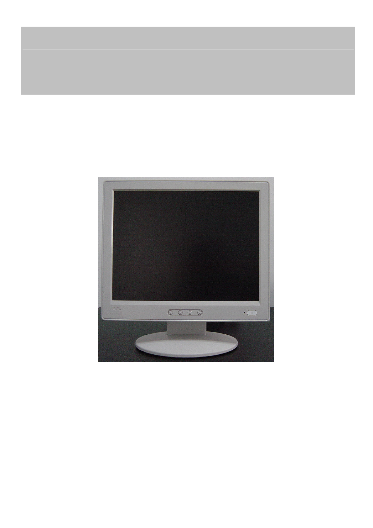
TCL MONITOR
LA560A-1
THESE DOCUMENTS ARE FOR REPAIR SERVICE INFORMATION ONLY.EVERY REASONABLE EFFORT
HAS BEEN MADE TO ENSURE THE ACCURACY OF THIS MANUAL; WE CANNOT GUARANTEE THE ACCURACY
OFTHIS INFORMATION AFTER THE DATE OF PUBLICATION AND DISCLAIMS RELIABILITY FOR CHANGES,
ERRORS OR OMISSIONS.
MANUFACTURE DATA :Mar-30-2005
Page 1 of 47
Page 2

TCL LA560A-1
Table Contents
TABLE CONTENTS......................................................................................................................................................... 2
REVISION LIST ............................................................................................................................................................... 4
1. MONITOR SPECIFICATIONS ..................................................................................................................................... 5
2. LCD MONITOR DESCRIPTION .................................................................................................................................. 6
3. OPERATING INSTRUCTIONS .................................................................................................................................... 7
3.1 GENERAL INSTRUCTIONS................................................................................................................................... 7
3.2 CONTROL BUTTON............................................................................................................................................... 7
3.3 ADJUSTING THE PICTURE................................................................................................................................... 7
4. INPUT/OUTPUT SPECFICATION ............................................................................................................................... 9
4.1 INPUT SIGNAL CONNECTOR ............................................................................................................................... 9
4.2 FACTORY PRESET DISPLAY MODES: ............................................................................................................ 10
4.3 POWER SUPPLY FEATURES ................................................................................................................................. 10
4.4 PANEL SPECIFICATION ...................................................................................................................................... 10
4.4.1 General Description ....................................................................................................................................... 10
4.4.2 DISPLAYS CHARACTERISTICS....................................................................................................................11
4.4.3 OPTICAL CHARACTERISTICS......................................................................................................................11
4.4.4 Backlight unit.................................................................................................................................................. 12
5. BLOCK DIAGRAM .................................................................................................................................................... 13
5.1 SOFTWARE FLOW CHART ................................................................................................................................. 13
5.2 MONITOR EXPLODED VIEWING ...................................................................................................................... 14
5.3 ELECTRICAL BLOCK DIAGRAM....................................................................................................................... 145
5.3.1 SCALAR BOARD BLOCK DIAGRAM............................................................................................................ 15
5.3.2 INVERTER/POWER BOARD BLOCK DIAGRAM ......................................................................................... 16
6.SCHEMATIC ............................................................................................................................................................... 18
6.1 MAIN BOARD ....................................................................................................................................................... 18
6.2 POWER BOARD................................................................................................................................................... 24
7. PCB LAYOUT ............................................................................................................................................................ 26
7.1 MAIN BOARD ....................................................................................................................................................... 26
7.2 POWER BOARD ....................................................................................................................................................... 26
8. MAINTAINABILITY.................................................................................................................................................... 27
8.1 EQUIPMENT AND TOOLS REQUIREMENT........................................................................................................ 27
8.2 TROUBLE SHOOTING......................................................................................................................................... 28
8.2.1 MAIN BOARD ................................................................................................................................................ 29
8.2.2 KEYPAD BOARD........................................................................................................................................... 31
8.2.3 POWER/INVERTER BOARD ........................................................................................................................ 32
Page 2 of 47
Page 3

TCL LA560A-1
9 WHITE-BALANCE, LUMINANCE ADJUSTMENT .................................................................................................... 34
10. EDID CONTENT ...................................................................................................................................................... 35
11. BOM LIST ................................................................................................................................................................ 36
Page 3 of 47
Page 4

Revision List
Revision Date Change Description
TCL LA560A-1
Page 4 of 47
Page 5
1. MONITOR SPECIFICATIONS
Monitor Modes TCL LA560A-1
Type 15.0”TFT
MAX DISPLAY AREA 304.128mm×228.096mm(W×H)
MAX RESOLUTION 1024×768(W×H)
DOT PITCH 0.099mm×0.297mm(W×H)
PIXEL PITCH 0.297mm×0.297mm(W×H)
COLOUR 16,777,216 (6Bit)
TCL LA560A-1
VIEWING ANGLE
CONTRAST
BRIGHTNESS 250cd/m
RESPONSE TIEM 25ms
HORIZONTAL FREQUENCY
VERTICAL FREQUENCY
INPUT SIGNAL
Signal Standard VESA DPMS
Drug & play VESA DDC2B
Picture control OSD
Power Consumption
Power AC220V
Weight 3kg
Dimension
Operating temperature
Max 25W(in save modes less than 3W)
356mm×150mm×355mm(W×D×H)
UP/ DOWN 40°/ 60°
LEFT/ RIGHT 60°/ 60°
RBG ANALOG(D-sub15)
400:1
2
30~60kHz
55~75 Hz
5℃~35℃
Operating humidity
Storing temperature
Storing humidity
10%~85%
-20℃~60℃
5%~85%
Page 5 of 47
Page 6
TCL LA560A-1
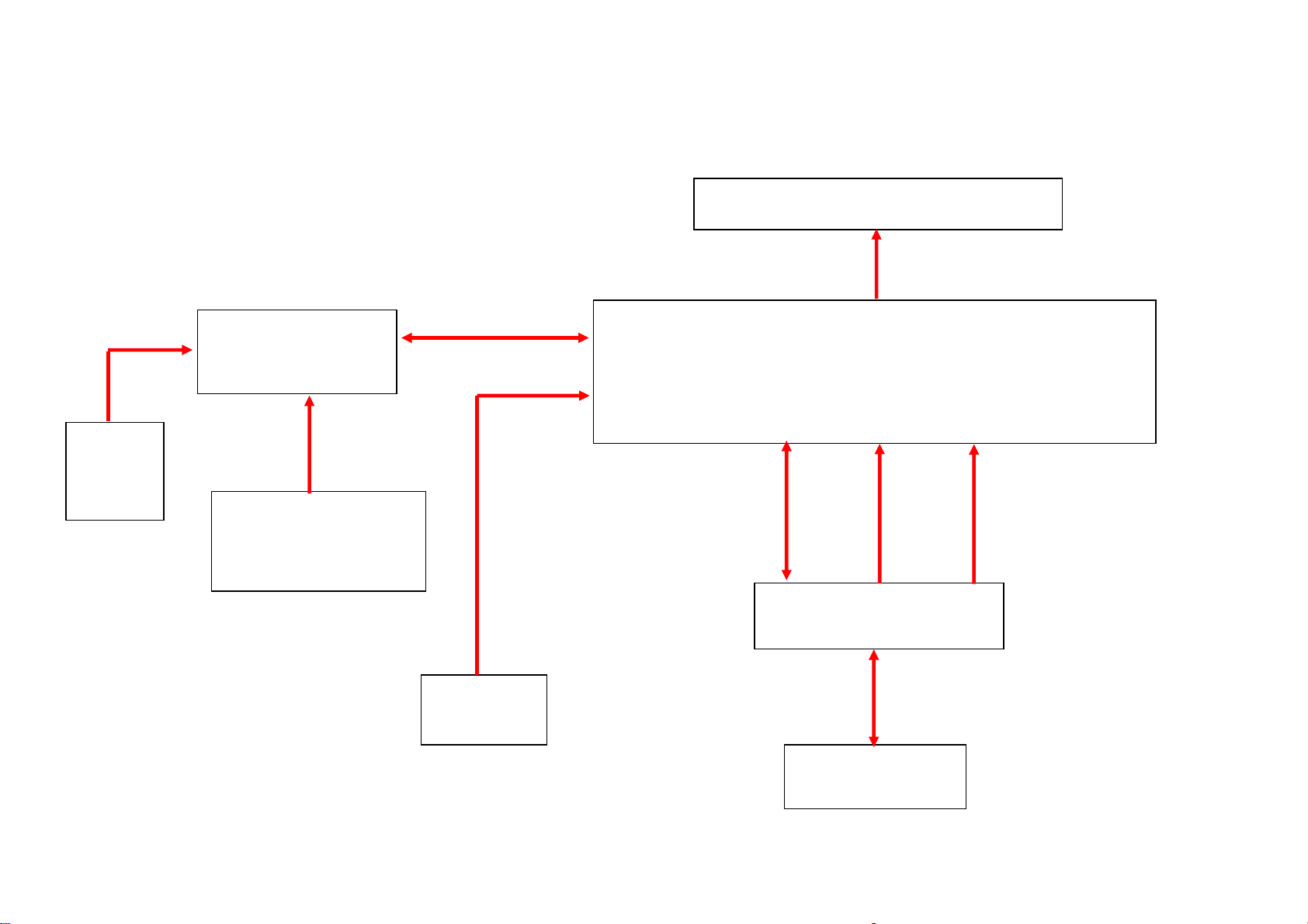
2. LCD MONITOR DESCRIPTION
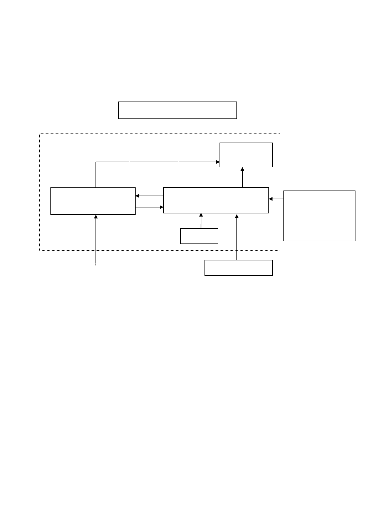
The LCD MONITOR will contain a main board, a power board and a keypad board which house the flat panel control
logic, brightness control logic and DDC.
The power board will provide AC to DC Inverter voltage to drive the backlight of panel and the main board chips each
voltage.
PWPC Board
(Include Adapter, Inverter)
AC-IN
100V-240V
Monitor Block Diagram
CCFL Drive.
Keyboard
Flat Panel and
CCFL backlight
Main Board
HOST Computer
RS232 Connector
For white balance
adjustment in factory
mode
Video signal, DDC
Page 6 of 47
Page 7
TCL LA560A-1
3. OPERATING INSTRUCTIONS
3.1 GENERAL INSTRUCTIONS
Press the power button to turn the monitor on or off. The other control buttons are located at the front of the monitor. By
changing these settings, the picture can be adjusted to your personal preferences.
The power cord should be connected.
-
Connect the video cable from the monitor to the video card.
-
Press the power button to turn on the monitor, the power indicator will light up.
-
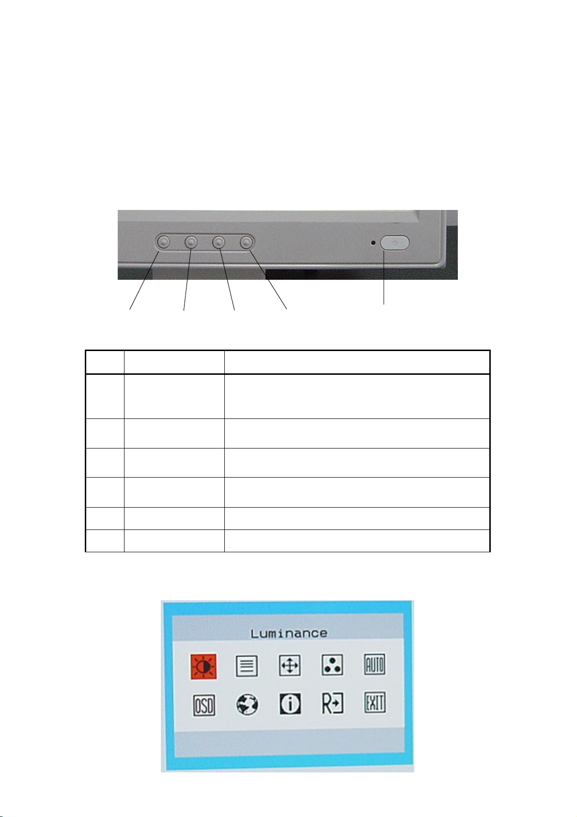
3.2 CONTROL BUTTON
①
②
③
④
⑤
Item Description
① AUTO/EXIT
②
③
④ MENU
⑤ ・LED Indication ・indicate the condition of power
⑥ ・Power ・Turn the monitor ON or OFF
・Brightness
・<
・Contrast
・>
3.3 ADJUSTING THE PICTURE
・Auto configuration (contains CLOCK,PHASE,H
POSITION,V POSITION)
・Exit OSD or back to previous menu
・Hot key to Brightness Adjust
Move the cursor to left
・
・Hot key to Contrast Adjust
Move the cursor to right
・
・Enter the OSD main menu
・Select Function or select Sub menu
or Decrease value
or Increase value
Page 7 of 47
Page 8
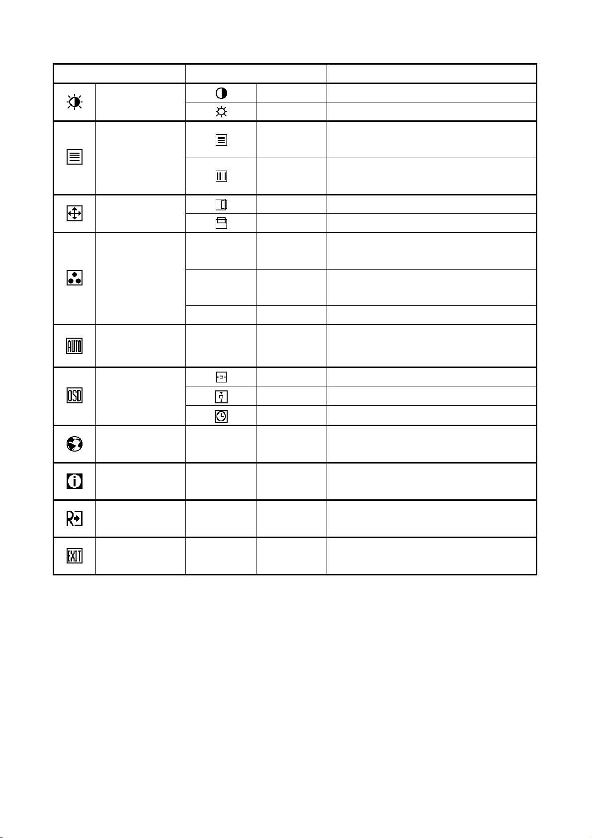
The description for control function:
Item Sub items Description
TCL LA560A-1
Luminance
Image Setup
Image Position
Color Temp
Auto Config N/A Auto Config
OSD Setup
Contrast
Brightness
Adjust the screen Contrast。
Adjust the screen Brightness。
Adjust Picture Phase to reduce
Focus
Horizontal-Line noise
Adjust picture Clock to reduce Vertical-Line
Clock
noise
H. Position Adjust the horizontal position of the picture
V. Position Adjust the vertical position of the picture
Recall Warm Color Temperature from
N/A Warm
EEPROM
Recall Cool Color Temperature from
N/A Cool
EEPROM
N/A User Red Gain from Digital-register.
Auto configuration contains Clock、Focus、
H. Position、V. Position
H. Position Adjust the horizontal position of the OSD.
V. Position Adjust the vertical position of the OSD.
OSD Timeout Adjust the OSD timeout.
Language N/A Language OSD language selection
Show the resolution, H/V frequency and input
Information N/A Information
port of current input timing.
Reset N/A Reset Reset to the factory preset mode
Exit N/A Exit Set and save and then quit the OSD
Page 8 of 47
Page 9
4. INPUT/OUTPUT SPECFICATION
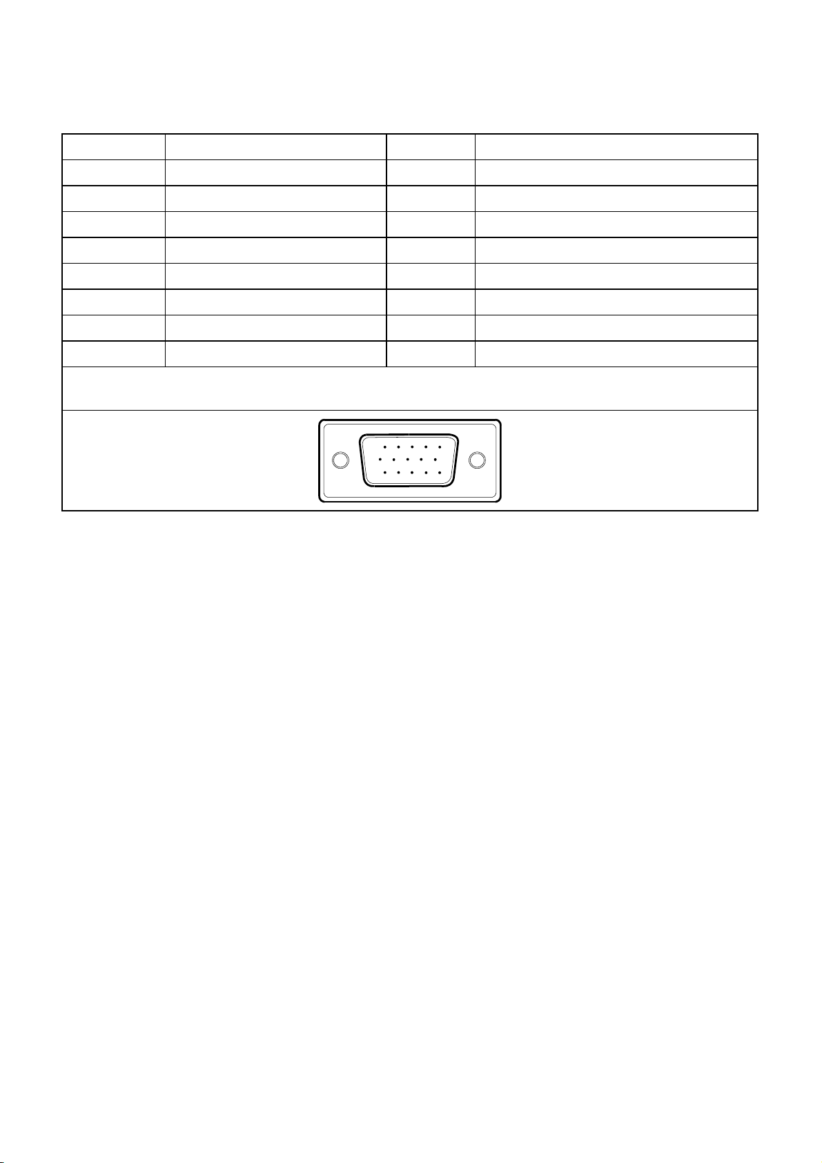
4.1 INPUT SIGNAL CONNECTOR
PIN NO. DESCRIPTION PI N NO. DESCRIPTION
1. Red Video 9. +5 v
2. Green Video 10. Logic Ground
3. Blue Video 11. RS-232 RX
4. RS-232 TX 12. DDC-Serial Data
5. DDC-Return 13. H-Sync.
6. Red Ground 14. V-Sync.
7. Green Ground 15. DDC-Serial Clock
8. Blue Ground
VGA Connector layout
15
6
11 15
10
TCL LA560A-1
Page 9 of 47
Page 10
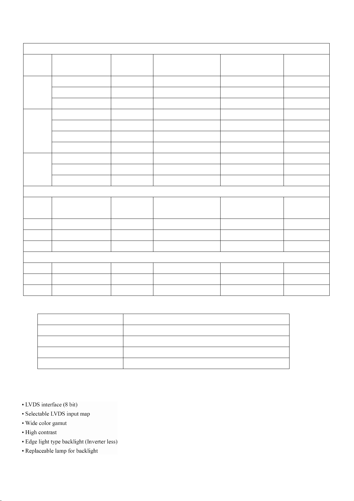
4.2 FACTORY PRESET DISPLAY MODES:
VESA MODES
TCL LA560A-1
Mode Resolution Total
640x480@60Hz 800 x 525 31.469 59.940 25.175
VGA
SVGA
XGA
Mode Resolution Total
DOS 720x400@70Hz 900 x 449 31.469 70.087 28.322
640x480@72Hz 832 x 520 37.861 72.809 31.500
640x480@75Hz 840 x 500 37.500 75.00 31.500
800x600@56Hz 1024 x 625 35.156 56.250 36.000
800x600@60Hz 1056 x 628 37.879 60.317 40.000
800x600@72Hz 1040 x 666 48.077 72.188 50.000
800x600@75Hz 1056x625 46.875 75.000 49.500
1024x768@60Hz 1344x806 48.363 60.004 65.000
1024x768@70Hz 1328x806 56.476 70.069 75.000
1024x768@75Hz 1312x800 60.023 75.029 78.750
Horizontal Frequency
+/- 0.5kHz
IBM MODES
Horizontal Frequency
+/- 0.5kHz
Vertical Frequency
+/- 1 Hz
Vertical Frequency
+/- 1 Hz
Nominal Pixel
Clock (MHz)
Nominal Pixel
Clock (MHz)
DOS 640x350@70Hz 800 x 449 31.469 70.087 25.175
XGA 1024x768@72Hz 1304x798 57.515 72.100 75.000
MAC MODES
VGA 640x480@67Hz 864x525 35.000 66.667 30.240
SVGA 832x624@75Hz 1152x667 49.725 74.551 57.2832
XGA 1024x768@75Hz 1328x804 60.241 74.927 80.000
4.3 POWER SUPPLY Features
A/C Line voltage range : 100 V ~ 240 V
A/C Line frequency range
Current : 0.6A max. at 100V , 0.35A max. at 240 V <0.3A
Peak surge current : < 55A peak at 240 VAC and cold starting
Leakage current : < 3.5mA
: 50 ± 3Hz, 60 ± 3Hz
4.4 PANEL SPECIFICATION
4.4.1 General Description
Page 10 of 47
Page 11
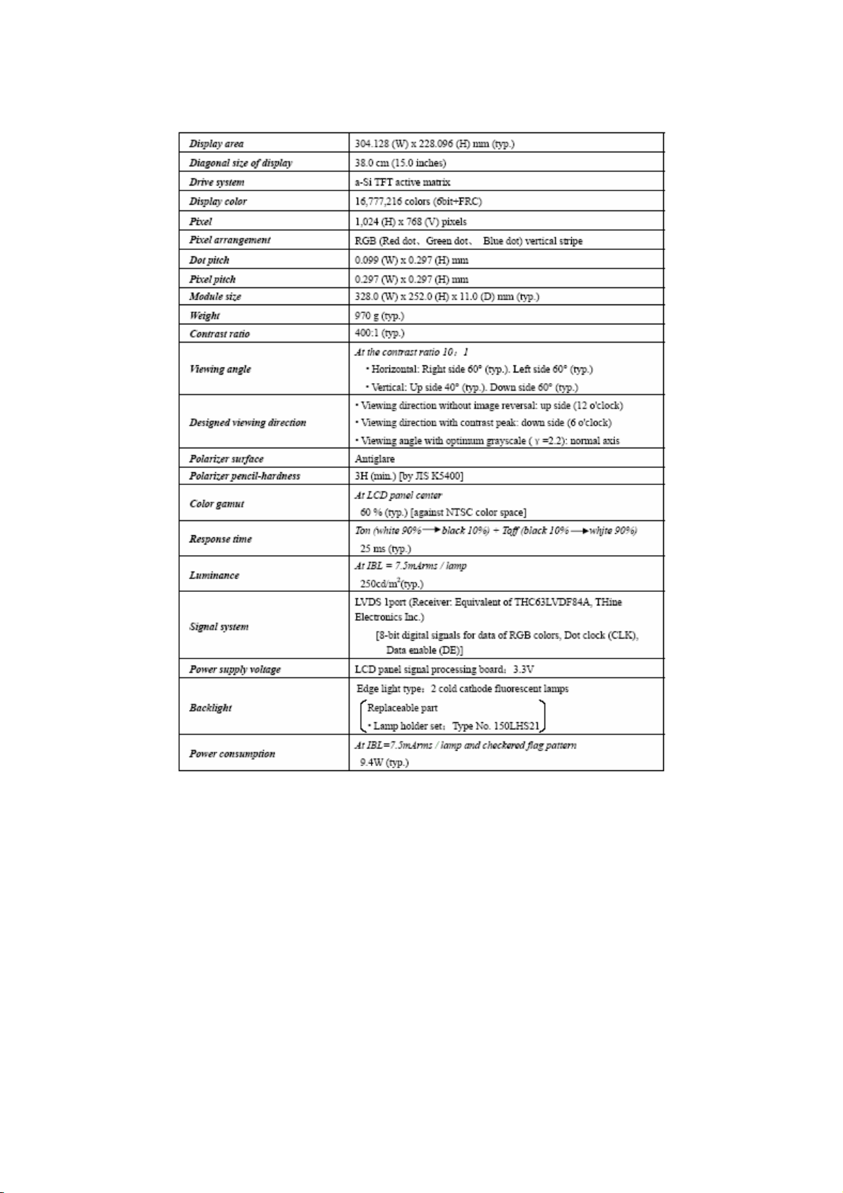
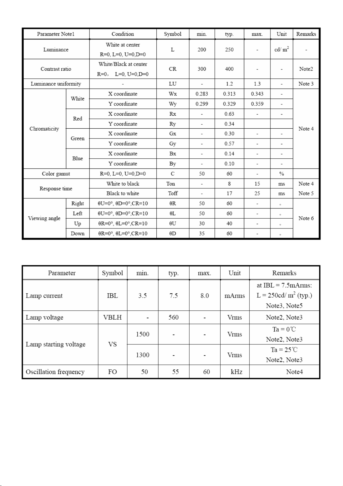
4.4.2 DISPLAYS CHARACTERISTICS
The following items are characteristics summary on the table under 25 ℃ condition:
TCL LA560A-1
4.4.3 OPTICAL CHARACTERISTICS
The optical characteristics are measured under the conditions as follows: Ta=25℃, Vcc=3.3V, IBL=7.5mArms/lamp,
Display mode: XGA, Horizontal cycle=48.363KHz, Vertical cycle=60.000Hz.
Page 11 of 47
Page 12
TCL LA560A-1
4.4.4 Backlight unit
Page 12 of 47
Page 13
5. BLOCK DIAGRAM
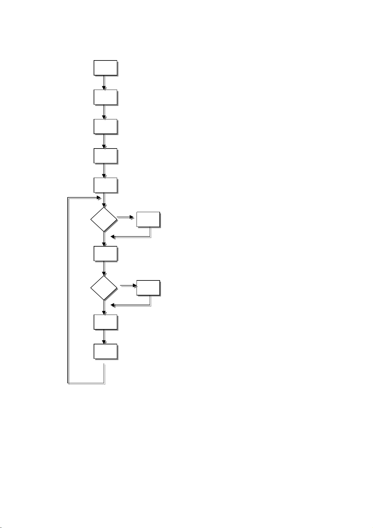
5.1 SOFTWARE FLOW CHART
TCL LA560A-1
N
(1)
(2)
(3)
(4)
(5)
(6)
Y
(7)
1) Initialize MCU settings, including I/O, Timer,
ISR and Serial Port settings.
2) Read EEPROM content to recover monitor
settings, including brightness, contrast, color
temperature and OSD position etc.
3) Initialize system variable, including system
flag, OSD timeout counter, burin mode
status… etc.
4) Initialize OSD menu variable for user operation
5) Initialize device on the board, now only MST
scalar chip will be initialized
6) Check if system is in power off status from first
AC power up. If yes, then go to 7, else go to 8.
7) If yes, system will be forced to enter power off
status Mode detection
8) Check if input timing has been changed, if yes
N
(8)
(9)
(11)
(12)
Y
(10)
then go to 10, else go to 11
9) Setup MST scalar for display according input
timing
10) OSD handler for OSD operation.
11) Debug handler, only debug only
Page 13 of 47
Page 14
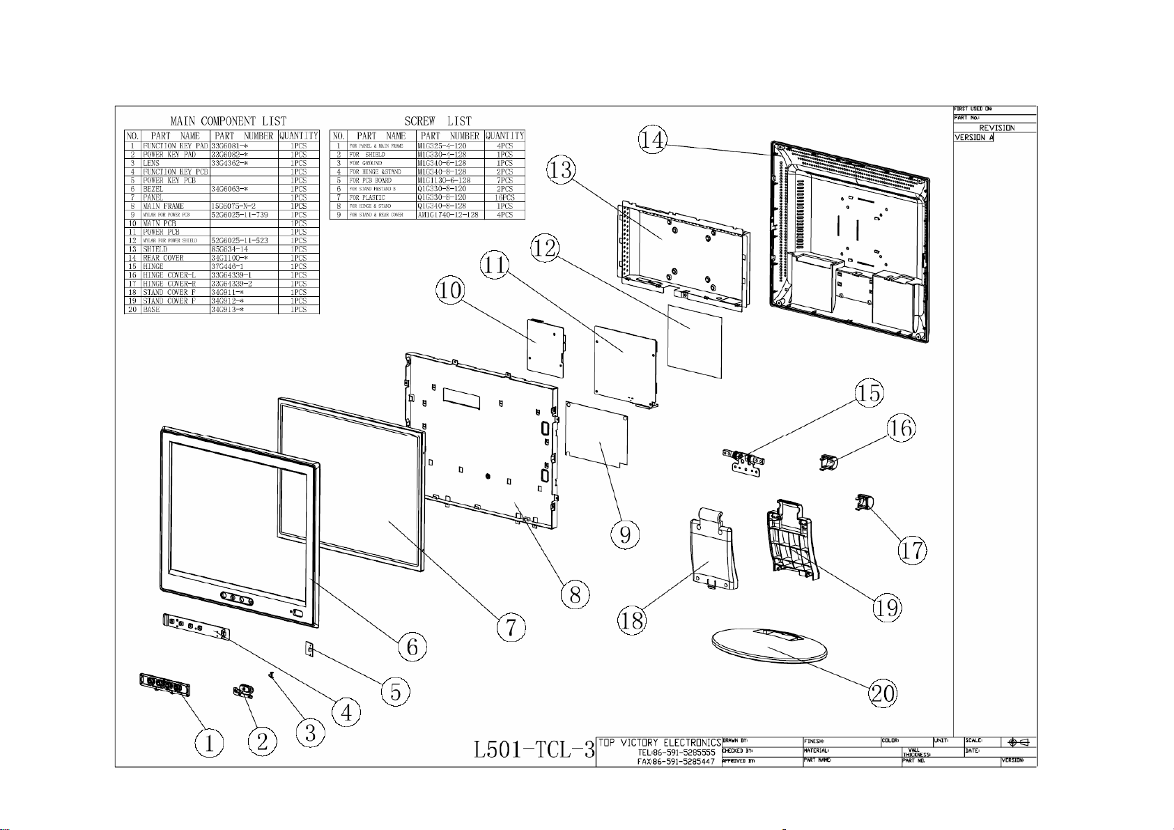
5.2 Monitor Exploded Viewing
BU1527
Page 14 of 47
Page 15
5.3 ELECTRICAL BLOCK DIAGRAM
5.3.1 SCALAR BOARD BLOCK DIAGRAM
BU1527
Crystal
24MHz
MCU
W78E65P-40
OSD Control Interface
(Keypad)
LCD Interface (LVDS)
Scalar
TSU16AK-LF
(Include ADC,OSD)
RXD
TXD
D-Sub Connector
RGB
Crystal
14.31818 MHz
EEPROM
Page 15 of 47
DB15_SDA
DB15_SCL
Page 16

Page 17

5.3.2 INVERTER/POWER BOARD BLOCK DIAGRAM
Inverter Block Diagram
TCL LA560A-1
Page 17 of 47
Page 18

TCL LA560A-1
Power Block Diagram
Page 18 of 47
Page 19

6. SCHEMATIC
6.1 MAIN BOARD
TCL LA560A-1
B2
VCPU
VAA4
VCC5V
VAA3
VAA2
VCC12V
VCC12V
VCC3.3
VCC2.5
VAA1
VCC5V
VCPU
B1
TXD
RXD
DDC_DAT
ST_DET1 HSYNC
ST_DET2
3.INPUT
B3
ST_DET2
ST_DET1
DDC_CLK
DDC_DAT
RXD
TXD
VCC5V
VCC12V
VCPU
onPANEL_5V/3.3V
onBACKLITE
6.MCU
B4
onBACKLITE
onPanel_5V/3.3V
VCPU
VCC12V
VCC3.3
AdjBACKLITE
VCC2.5
VAA1
VAA2
VAA3
VAA4
VCC5V
GNDR
GNDG
SOGDDC_CLK
GNDB
VSYNC
CLK+
CLK-
CSZ
SCL
SDA
HWRESET
AD0
AD1
AD2
AD3
Volume
VLCD
RIN
GIN
BIN
INT
RIN
GNDR
GIN
GNDG
SOG
BIN
GNDB
HSYNC
VSYNC
VCC2.5
VCC3.3
R+
R-
G+
G-
B+
B-
R+
RG+
GB+
BCLK+
CLK-
CSZ
SCL
SDA
HWRESET
INT
AD0
AD1
AD2
AD3
Volume
VAA1
VAA2
VAA4
PA[0..9]
PB[0..9]
VCC2.5
VAA3
VCC3.3
PA[0..9]
PB[0..9]
VAA1
VAA2
B5
PA[0..9]
PB[0..9]
VAA3
VAA4
VLCD
VLCD
5.PANEL INTERFACE
VLCD
AdjBACKLITE
4.SCALER
2.POWER
Page 19 of 47
Page 20

TCL LA560A-1
VCC5V
GND
GND
VCC12V
GND
VCC5V
GND
VCC12V
C205
0.1uF
VCC12V 6
VCC5V+
VCC5V
VCC5V 3,4,6
VCPU
VCPU 6
C201
0.1uF
CN201
ON_OFF
CONN
VCC5V
2
4
6
8
10
12
R203
1K 1/16W
DIM
VCC12V
GND
VCC5V
GND
C202
220uF/25V
R201 4.7K 1/16W
D201 SS14
FB201
600 OHM
+
C203
0.1uF
C204
+
220uF/25V
1
3
5
7
9
11
R202
10K 1/16W
32
Q201
PMBS3904
R212 4.7K 1/16W
1
C
BE
onBACKLITE 6
Brightness
AdjBACKLITE4
R205 4.7K 1/16W
32
Q202
1
PMBS3904
C206
1uF/25V
VCC5V+
R204
10K 1/16W
C
BE
C214
0.1uF
VCC5V+
TO-263
U202
AIC1084-33M
3
VIN
1
ADJ
D202
GS1D
C210
0.1uF
VOUT
SOT-252
U201
RT9164
3 2
VI VO
2
C215
47uF/16V
VCC2.5
VCC2.5 4
+
C211
GND
1
+
47uF/16V
VCC3.3
C216
0.1uF
C212
0.1uF
VCC3.3 4
VAA1
VAA1 4
VAA2
VAA2 4
VAA3
VAA3 4
VAA4
VAA4 4
NEW
Circuit
C207
0.1uF
VCC5V
R208
10K 1/16W
R215
32
Q204
1
PMBS3904
100K 1/16W
VCC5V
R206
10K 1/16W
onPanel_5V/3.3V6
R207
4.7K 1/16W
R214 delete
R216
4.7K 1/16W
VLCD
Q203
AO3401
C217
0.068uF
+
C208
100uF/16V
Page 20 of 47
VLCD 5
VCC5V
0 1/16W
R211
10K 1/16W
R209
VCC3.3
VCC12V
R210
R213
NC
NC
Page 21

D323
D322
TZMC5V6-GS08
TZMC5V6-GS08
TCL LA560A-1
CN301
DB15
11
12
13
14
15
HSI
VSI
1
6
2
7
3
8
4
PC5V
9
5
10
VGA_CON
RXD 6
TXD 6
3
D301
BAV99
2
FB304 150 OHM
R312 100 1/16W
3
1
2
D302
BAV99
1
FB301 0 1/16W
FB302 0 1/16W
FB303 0 1/16W
3
D303
BAV99
1
2
75 1/16W
VCC5V
R325
C301
NC
R326
75 1/16W
C302
NC
R327
75 1/16W
C303
NC
R301 100 1/16W
R302 100 1/16W
R303 100 1/16W
R304 470 1/16W
R305 100 1/16W
R306 100 1/16W
R307 100 1/16W
VCC5V
R308
10K 1/16W
R309 100 1/16W
R310 1K 1/16W
R311 1K 1/16W
C304 0.047uF
C305 0.047uF
C306 0.047uF
C307 0.001uF
C308 0.047uF
C309 0.047uF
C310 0.047uF
ST_DET1 6
HSYNC 4
VSYNC 4
RIN 4
GIN 4
BIN 4
SOG 4
GNDR 4
GNDG 4
GNDB 4
VCC5V
3
PC5V
2
D304
BAV70
CN302
RGB GND
HSYNC
VSYNC
SYNC GND
DDC SCL
DDC SDA
1/3shield
2/4shield
0/5shield
clk shield
DAT0+
DAT0-
DAT1+
DAT1-
DAT2+
DAT2-
DAT3+
DAT3-
DAT4+
DAT4-
DAT5+
DAT5-
JACK
D319
TZMC5V6-GS08
25
R
26
G
27
B
29
28
8
15
6
7
14
+5V
16
HPD
11
3
19
22
18
17
10
9
2
1
13
12
5
4
21
20
23
clk+
24
clk-
VCC5V
D320
TZMC5V6-GS08
D321
TZMC5V6-GS08
CLK_DDC2
DAT_DDC2
3
2
D306
BAV99
1
3
2
D318
TZMC5V6-GS08
D314
LL5232B 5.6V 5%
D307
BAV99
2
1
R319 100 1/16W
R320 100 1/16W
D315
LL5232B 5.6V 5%
3
D308
BAV99
1
2
C312
220pF
R322 100 1/16W
3
D312
BAV99
2
1
3
D313
BAV99
D317
TZMC5V6-GS08
1
ST_DET2 6
B+ 4
B- 4
G+ 4
G- 4
R+ 4
R- 4
CLK+ 4
CLK- 4
R315 100 1/16W
R316 100 1/16W
DDC_DAT6
DDC_CLK6
R317
10K 1/16W
R323
10K 1/16W
R318
10K 1/16W
VCC5V
R324
10K 1/16W
1
U301
8
7
6
DVI5V
2
3
1
8
7
6
VCC
WP
SCL
GNDSDA
M24C02WMN6
D305
BAV70
U302
VCC
WP
SCL
M24C02WMN6
A0
A1
A2
A0
A1
A2
GNDSDA
C313
0.1uF
1
2
3
45
C315
1
0.1uF
2
3
45
C311
33pF
2
DVI5V
3
R314
10K 1/16W
R321
10K 1/16W
C314
0.1uF
D311
BAV99
1
R313
2.2K 1/16W
CLK_DDC
DAT_DDC
D316
LL5232B 5.6V 5%
3
D309
BAV99
2
3
D310
BAV99
1
1
2
Page 21 of 47
Page 22

TCL LA560A-1
VDVI
RIN3
GNDR3
GIN3
GNDG3
SOG3
BIN3
GNDB3
HSYNC3
VSYNC3
R+3
R-3
G+3
G-3
B+3
B-3
CLK+3
CLK-3
R403 390 1/16W
CSZ6
SCL6
SDA6
HWRESET6
AdjBACKLITE2
Volume6
C402 22pF
14.318MHz
C403 22pF
C404 0.1uF
VCC3.3
VCC3.32
VDPLL
VDVI
VAD
VPLL
55
35
4535111218494
65
U401
AVDD
AVDD
63
RIN0
62
RIN0M
60
GIN0
59
GIN0M
61
SOGIN0
58
BIN0
57
BIN0M
37
HSYNC0
38
VSYNC0
29
DDC1_CLK/GPO8
28
DDC1_DAT/GPO7
40
R+
41
R-
43
G+
44
G-
46
B+
47
B-
49
CK+
50
CK-
52
66
67
69
71
70
32
72
73
74
33
34
REXT
REFP
REFM
CSZ
SCL
SDA
HWRESETZ
INT
PWM0
PWM1
XIN
XOUT
BYPASS
AVSS_LPLL
AVSS
68
C401
0.1uF
INT6
X401
56
AVSS
64
AVSS
AVDD_MPLL
AVSS_MPLL
36254
AVDD_DVI
AVDD_DVI
AVSS_PLL
104
53
VDDP
VDDP
VDDP
VDDP
AVDD_PLL
MST8031/8131
AVSS_DVI
GNDP
GNDP
AVSS_DVI
AVSS_DVI
39
4210208595
48
114
126188797117
VDDP
VDDP
VDDP
GNDP
GNDP
GNDP
GNDP
115
105
VDDVPO
VDDC
VDDC
VDDC
VDDC
LVA3P
LVA3M
LVACKP
LVACKM
LVA2P
LVA2M
LVA1P
LVA1M
LVA0P
LVA0M
NC/LVB3P
NC/LVB3M
NC/LVBCKP
NC/LVBCKM
NC/LVB2P
NC/LVB2M
NC/LVB1P
NC/LVB1M
NC/LVB0P
NC/LVB0M
ADO/NC
AD1/NC
AD2/NC
AD3/NC
BUS TYPE/NC
GNDP
GNDC
GNDC
1271986
96
GNDC
116
GNDC
PA0
102
PA1
103
PA2
106
PA3
107
PA4
108
PA5
109
PA6
110
PA7
111
PA8
112
PA9
113
PB0
118
PB1
119
PB2
120
PB3
121
PB4
122
PB5
123
PB6
124
PB7
125
PB8
128
PB9
1
VCC5V
R407
10K 1/16W
30
77
78
31
6
R405
10K 1/16W
10K 1/16W
Direct Bus
3-WIRE
R404
R406
10K 1/16W
R401
NC
4.7K
PA[0..9]
PB[0..9]
FB401
600 OHM
C405
10uF/16V
AD0 6
AD1 6
AD2 6
AD3 6
R402
4.7K
NC
VPO
+
PA[0..9] 5
PB[0..9] 5
C406
0.1uF
VCC3.3
C408
C407
0.1uF
0.1uF
R402
100 1/16W
R401
NC
C409
0.1uF
C410
0.1uF
C411
0.1uF
VCC2.52
C412
C413
0.1uF
0.1uF
VAA12
VAA22
VAA32
VAA42
Title
Size Document Number Rev
B
Date: Sheet
MST8031/ MST8131 for AOC
SCALER
VCC2.5
VAA1
VAA2
VAA3
VAA4
FB402
600 OHM
C414
10uF/16V
FB403
600 OHM
10uF/16V
FB404
600 OHM
10uF/16V
FB405
600 OHM
10uF/16V
FB406
600 OHM
10uF/16V
C419
C422
C424
C427
VDD
+
VAD
VPLL
VDVI
VDPLL
46Wednesday, April 14, 2004
+
+
+
+
C415
0.1uF
C420
0.1uF
C423
0.1uF
C425
0.1uF
C428
0.1uF
of
C416
0.1uF
C421
0.1uF
C426
0.1uF
C417
0.1uF
C418
0.1uF
D
Page 22 of 47
Page 23

TCL LA560A-1
PA[0..9]4
PB[0..9]4
PA[0..9]
PB[0..9]
PA0
PA1
PA2
PA3
PA4
PA5
PA6
PA7
PA8
PA9
PB0
PB1
PB2
PB3
LVA3P
LVA3M
LVACKP
LVACKM
LVA2P
LVA2M
LVA1P
LVA1M
LVA0P
LVA0M
LVB3P
LVB3M
LVBCKP
LVBCKM
LVB0M
LVB1M
LVB2M
LVBCKM
LVB3M
LVA0M
LVA1M
LVA2M
LVACKM
LVA3M
RXO0RXO1RXO2RXOCRXO3RXE0RXE1RXE2RXECRXE3-
11
13
15
17
19
21
23
1
3
5
7
9
CN503
2
4
6
8
10
12
14
16
18
20
22
24
RXO0+
RXO1+
RXO2+
RXOC+
RXO3+
RXE0+
RXE1+
RXE2+
RXEC+
RXE3+
LVB0P
LVB1P
LVB2P
LVBCKP
LVB3P
LVA0P
LVA1P
LVA2P
LVACKP
LVA3P
PB4
PB5
PB6
PB7
PB8
PB9
LVB2P
LVB2M
LVB1P
LVB1M
LVB0P
LVB0M
C509
+
22uF/16V
CONN
C510
0.1uF
VLCD
VLCD 2
C511
0.1uF
R502
0 1/16W
Page 23 of 47
Page 24

OUT-L+
OUT-L-
11
13
1
3
5
7
9
CN601
CON14A
VCPU
U603 MAX810STR (NC)
Reset
Circuit
2
4
6
8
10
OUT-R+
12
OUT-R-
14
RSTVCC
GND
1
C605
0.1uF
23
U602
1
A0
2
A1
3
A2
4 5
GND SDA
AT24C16N-10SC-2.7
FB601 600 OHM
FB602 600 OHM
C613
0.1uF
FB603
600 OHM
100pF
C617
VCC
WP
SCL
VCC5V
VCC12V
C612
0.1uF
8
7
6
VCPU2
LL4148-GS08
VCPU
R638 NC
VCC12V 2
VCC5V 2,3,4
R627 10K 1/16W
R626 10K 1/16W
VCC5V
R640
NC
R625 10K 1/16W
C611
1uF/25V
R603
D601
10K 1/16W
R604 10K 1/16W
R605 10K 1/16W
R639 100 1/16W
VCC5V
R643
NC
Q604
32
NC
1
LED_G
AUTO
RIGHT
POWER
C602 22pF
+
C603
10uF/16V
C604 22pF
INT4
R608 100 1/16W
R609 100 1/16W
R615 10K 1/16W
R614 10K 1/16W
Standby
ST_DET13
ST_DET23
R641 NC
R642 0 1/16W
R616
4.7K 1/16W
R620 470 1/16W
R622 470 1/16W
R624 470 1/16W
10K 1/16W
X601
20MHz
Mute
Volume 4
VCPU
1
C606
0.001uF
R617
470 1/16W
Q601
PMBS3906
3 2
C608
0.001uF
R601
R602
10K 1/16W
35
21
20
10
12
14
15
33
32
VCPU
R632
NC
DVI-DSUB SELECT
LED_GRN
C610
0.001uF
U601
EA/VP
XTAL1
XTAL2
RESET
P4.3
INT0/P3.2
INT1/P3.3
ALE/P
PSEN
2
P1.0
3
P1.1
4
P1.2
5
P1.3
6
P1.4
7
P1.5
8
P1.6
9
P1.7
8051-PLCC
R631
NC
OUT-L+
OUT-L-
C601
0.1uF
R630 NC
R633 NC
VCPU
22 44
P3.6/WR
P3.7/RD
P3.1/TXD
P3.0/RXD
VSS VCC
CN602
1
3
5
7
9
11
13
15
10K 1/16W
P0.0
P0.1
P0.2
P0.3
P0.4
P0.5
P0.6
P0.7
P2.0
P2.1
P2.2
P2.3
P2.4
P2.5
P2.6
P2.7
T0/P3.4
T1/P3.5
C614
NC
CON16A
RN601
876
123
43
42
41
40
39
38
37
36
24
25
26
27
28
29
30
31
16
17
18
19
13
11
DVI-DSUB SELECT
Mute_key
C615
NC
LED_BLUE
2
LED_ORANGE
4
6
8
10
12
14
16
5
876
5
RN602
10K 1/16W
4
123
4
R606 10K 1/16W
R607 10K 1/16W
R610 NC
R611 NC
R634 100 1/16W
R635 100 1/16W
VCPU
Mute_key
OUT-R+
OUT-R-
CN603
1
2
3
4
R637 10K 1/16W
POWER
ENTER
RIGHT
LEFT
AUTO
LED_B
LED_O
LED_G
C616
1uF/25V
R636 0 1/16W
R613
R612
10K 1/16W
NC
VCPU
R628
0 1/16W
Q603
PMBS3906
3 2
C607
0.001uF
C618
0.1uF
1
R629
4.7K 1/16W
R621 470 1/16W
R623 470 1/16W
C609
0.001uF
VCPU
ENTER
LEFT
HWRESET 4
onPANEL_5V/3.3V 2
onBACKLITE 2
CSZ 4
SCL 4
SDA 4
AD0 4
AD1 4
AD2 4
AD3 4
DDC_DAT 3
DDC_CLK 3
TXD 3
RXD 3
VCPU
LED_B
R618
470 1/16W
Q602
PMBS3906
3 2
TCL LA560A-1
1
R619
4.7K 1/16W
LED_O
Page 24 of 47
Page 25

6.2 POWER BOARD
+12V
+
NO/OFF
DIM
+
C201
470uF/16V
R201
37.5K
C207
33uF/50V
R207
NC
C203
1uF/25V
C202
0.1uF/25V
Q201
DTC144WKA
R210
12K 1/16W
R205
47K
C205
0.1uF/25V
15
16
SCP
REF
CTRT1IN+
1234567
TCL LA560A-1
TP3
HVL
TP1
HVO
Q203 SI4431DY-T1
1
2
3
R212
4
R214
2.2K 1/16W
C225
Q202
DTA144WKA
R208
4.7K 1/16W
C209
1uF/25V
11
12
13
14
2IN-
2IN+
2FBK
2DTC
1IN-
1FBK
1DTC
1uF/25V
10
2OUT
1OUT
C204
0.1uF
U201
GND Vcc
TL1451
8 9
R219
1K 1/16W
R218
100 1/16W
3.9K 1/16W
Q205
MPS3904
Q207
MPS3906
R216
220 1/16W
8
7
6
5
C211
1uF/25V
L201
L
D201
SM240A
D203
RLZ11B
R220
15K
R222
12K 1/16W
R240
51K 1/16W
C221
0.47uF/25V
R224
1K 1/16W
Q209
2SC5706
1
R225
1K 1/16W
C213
.15uF/160V
23
D207
1N4148
R238
12K 1/16W
R226
1K 1/16W
Q210
23
2SC5706
C219
1uF/25V
1
R227
1K 1/16W
910 1/16W
R236
620 1/10W
PT201
5 9
3,4
2
6
POWER X'FMR
R234
71
1
39pF/3KV
39pF/3KV
C215
C216
R232
1K 1/16W
is power GND
1
C226
39pF/3KV
C227
39pF/3KV
L202
1 4
2 3
TRANSFORMER
D209
1N4148
TP4
HVL
1
CN201
1
2
CONN
CN202
1
2
CONN
D205
1N4148
C208
330pF
R204
10K 1/16W
is signal GND
Page 25 of 47
Page 26

TCL LA560A-1
1
C904 0.47uF/250V
R901
1M 1/16W
C901
0.001uF/160V
SOCKET
4
BD901
2KBP06M
3
-+
2
2
3
L902
L
1
4
R902
1M 1/16W
NR901
NTCR
t
F901
FUSE
C902
0.001uF/160V
3
12
CN901
1
2
D906
1N4148
CN902
NC
D904
1N4148
D905
1N4148
SW_ON/OFF
GND
ZD905
RLZ20B
C905
+
100uF/450V
R909
4.7K 1/16W
ZD901
RLZ20B
R912
100 1/16W
C908
0.1uF
R916
24K 1/10W
R913
NC
R906
1M 1/4W
R907
1M 1/4W
IC901
SG6841
R915
10K 1/16W
72
8
4
SG6841
56
13
R914
NC
Q901
2PA733P
C910
0.1uF
1 2
C911
0.001uF
C909
0.1uF
R911
4.7K 1/16W
R904
1M 1/4W
R905
1M 1/4W
R917
JUMPER
C912
NC
R910
4.7K 1/16W
Q902
2PC945P
C906
0.0015uF/2KV
D902
PS102R
+
C907
22uF/50V
R918
20K 1/4W
R920
47 1/2W
T901
1
O
9
R903
100K 2W
D901
FR107
3
5
R908
10 1/16W
Q903
2SK2996
R919
0.39 2W
D903
1N4148
FB901
BEAD
O
6
POWER X'FMR
C913
0.0047uF/250V
43
IC903
HTL431
O
7,8
7,8
10,11
12
R922
47 1/4W
IC902
PC123FY2 4P
C936
0.1uF
PHONEJACK
C920
D910 31DQ10
C921
0.001uF/500V
D912
31DQ06
R930
470 1/4W
R931
1K 1/16W
R929
0 1/16W
CN301
1
4
3
2
5
0.001uF/500V
C935
0.01uF
+
C922
1000uF/16V
+
C925
1000uF/16V
ZD902
HZ12B2
R927
1K 1/10W
R928
1K 1/10W
L903
L904
ZD903
HZ5C1
+
+
R924
11K 1/10W
R926
24K 1/10W
C924
470uF/16V
C926
470uF/16V
R925
18K 1/10W
F902
FUSE
ZD904
SML4737A/1
FB902
BEAD
C928
0.1uF
C927
0.1uF
FB903
BEAD
TO INVERTER
CN102
12
11
10
9
8
7
6
5
4
3
2
1
CONN
CN302
3
2
1
CONN
12V
GND
GND
GND
5V
5VA
DIM
ON/OFF
INR
GND
INL
Page 26 of 47
Page 27

7. PCB LAYOUT
7.1 MAIN BOARD
TCL LA560A-1
7.2 Power Board
Page 27 of 47
Page 28

8. MAINTAINABILITY
8.1 EQUIPMENT AND TOOLS REQUIREMENT
1、Voltmeter.
2.、Oscilloscope.
3、Pattern Generator.
4、DDC Tool with a IBM Compatible Computer.
5、Alignment Tool
6、LCD Color Analyzer.
7、Service Manual.
8、User Manual
TCL LA560A-1
Page 28 of 47
Page 29

7.2 TROUBLE SHOOTING
7.2.1 MAIN BOARD
No power
TCL LA560A-1
Please reinsert and make sure
the AC of 100-240V is normal
Measure U201 PIN2=2.5V
U202 PIN2=3.3V
X401 and X601 oscillate
waveforms are normal
No power
Press power key and look
if the picture is normal
NG
NG
OK
NG
OK
Reinsert or check
the power section
Check Correspondent
component.
OK
Replace U601
NG
Replace U401
NG
Replace X401, X601
Page 29 of 47
Page 30

No picture (LED orange)
TCL LA560A-1
No picture
The button if under
OK
Measure U202 PIN2=3.3V
U201 PIN2=2.5V
OK
X401 oscillate
waveform is normal
OK
Replace U401
NG
NG
NG
X601 oscillate
waveform is normal
OK
Replace U601
Check Correspondent
component
Check Correspondent
component
NG
Check
Correspondent
component.
Page 30 of 47
Page 31

White screen
TCL LA560A-1
White screen
Measure Q204 base
is high level?
Check Correspondent
component
OK
NG
Check Q203 is broken or
CN503 solder?
NG
OK
Replace PANEL
Measure U202 PIN2=3.3V
U201 PIN2=2.5V
NG
OK
Check Correspondent
component
X401 oscillate
waveform is normal
OK
NG
Check Correspondent
component
Replace U401
Page 31 of 47
Page 32

7.2.2 KEYPAD BOARD
TCL LA560A-1
OSD is unstable or not working
Is Key Pad Board connecting
normally?
Y
Is Button Switch normally?
Y
Is Key Pad Board Normally?
Y
Check Main Board
N
N
N
Connect Key Pad
Replace Button Switch
Replace Key Pad
Page 32 of 47
Page 33

7.2.3 POWER/INVERTER BOARD
1.) No power
Check CN902 pin2, 4 = 12V
TCL LA560A-1
Check AC line volt 110V or 220V
Check the voltage of C905(+)
Check start voltage for the pin3 of IC901
NG
OK
OK
OK
NG
NG
NG
Check AC input
Check bridge rectified circuit and F901 circut
Check R906,R907 and Change IC901
Check the auxiliary voltage is bigger than
10V and smaller than 20V
NG
OK
Check IC901 pin8 PWM wave
NG
OK
Check Q901, R914,T901,D910,D911,ZD902
1) Check IC901
2) Check ZD901,Q902, Q903…OVP circuit
Check IC901
Page 33 of 47
Page 34

2.) No Backlight
TCL LA560A-1
Check C201 (+) =12V
NG OK
Change F902
Check ON/OFF signal
NG
OK
Check main board
Check U201 pin9=12V
OK
NG
Change Q201 or Q202
Check the pin1 of U201 have sawtooth wave
Change U201
Check D201/D202 have the output of square wave at short time
NG
Check Q205/Q207/Q203/D201
OK
Check the resonant wave of pin2 & pin5 for PT201/PT202
OK
NG
Check Q209/Q210/C213
Check the output of PT201
OK
NG
Change PT201
Check connecter & lamp
Page 34 of 47
Page 35

TCL LA560A-1
9 white-Balance, Luminance adjustment
Approximately 30 minutes should be allowed for warm up before proceeding White-Balance adjustment.
1. How to do the Chroma-7120 MEM. Channel setting
A. Reference to chroma 7120 user guide
B. Use “ SC” key and “ NEXT” key to modify XyY value and use “ID” key to modify the
TEXT description Following is the procedure to do white-balance adjust
2. Setting the color temp. you want
A. MEM.CHANNEL 3 (7800 color):
7800 color temp. parameter is x = 296 ±25, y = 311 ±25
B. MEM.CHANNEL 4 (6500 color):
6500 color temp. parameter is x = 313±25, y = 329 ±25.
3. Into factory mode of LA560A-1
Press MENU button during 2 seconds along with press Power button will activate the factory mode, then MCU will do
,
AUTO LEVEL automatically. Meanwhile press MENU the OSD screen will be located at LEFT TOP OF PANEL.
4. Bias adjustment:
Set the Contrast
to 50; Adjust the Brightness to 80.
5. Gain adjustment:
Move cursor to “-F-” and press MENU key
A. Adjust C2 (7800) color-temperature
1. Switch the Chroma-7120 to RGB-Mode (with press “MODE” button)
2. Switch the MEM. Channel to Channel 3 (with up or down arrow on chroma 7120)
3. The LCD-indicator on chroma 7120 will show x = 296 ±25, y = 311 ±25, Y = 200 ±10 cd/m
2
4. Adjust the RED of color1 on factory window until chroma 7120 indicator reached the value R=100
5. Adjust the GREEN of color1 on factory window until chroma 7120 indicator reached the value G=100
6. Adjust the BLUE of color1 on factory window until chroma 7120 indicator reached the value B=100
7. Repeat above procedure (item 4,5,6) until chroma 7120 RGB value meet the tolerance =100±2
B. Adjust C1 (6500) color-temperature
1. Switch the chroma-7120 to RGB-Mode (with press “MODE” button)
2. Switch the MEM.channel to Channel 4(with up or down arrow on chroma 7120)
3. The LCD-indicator on chroma 7120 will show x = 313 ±25, y = 329 ±25, Y = 200 ±10 cd/m
2
4. Adjust the RED of color3 on factory window until chroma 7120 indicator reached the value R=100
5. Adjust the GREEN of color3 on factory window until chroma 7120 indicator reachedthe value G=100
6. Adjust the BLUE of color3 on factory window until chroma 7120 indicator reached the value B=100
7. Repeat above procedure (item 4,5,6) until chroma 7120 RGB value meet the tolerance =100±2
C. Turn the Power-button off to quit from factory mode.
Page 35 of 47
Page 36

TCL LA560A-1
10. EDID CONTENT
ANALOG (D-SUB) INPUTS
00 01 02 03 04 05 06 07 08 09 10 11 12 13 14 15
0 00 FF FF FF FF FF FF 00 50 6C 62 C5 34 35 36 33
16 10 0F 01 03 68 1E 17 82 2A 36 4D 9F 57 4C 95 25
32 1C 4D 54 AF CE 00 61 40 61 4F 45 40 45 4F 31 40
48 31 4F 01 01 01 01 64 19 00 40 41 00 26 30 18 88
64 36 00 30 E4 10 00 00 18 00 00 00 FF 00 31 33 32
80 36 35 34 38 37 39 30 31 32 0A 00 00 00 FD 00 37
96 4B 1E 3F 08 00 0A 20 20 20 20 20 20 00 00 00 FC
112 00 54 46 54 31 35 36 30 50 53 0A 20 20 20 00 7D
Page 36 of 47
Page 37

11. BOM LIST
T562KVXMDTTEN
Location Part Numver Description Quantity Unit
CBPC562KVXTN CONVERSION BOARD 1 PCS
KEPC562KT2 KEY BOARD 1 PCS
PWPC5215A1E9C POWER BOARD 1 PCS
S95G801820536 LCDS ASS'Y 1 PCS
15G5908 2 BRACKET 1 PCS
15G6075 N 2 MAIN FRAME 1 PCS
33G4362 1 LENS 1 PCS
33G6081 Y L KEY PAD 1 PCS
33G6082 Y L POWER KEY 1 PCS
34G6063 Y L BEZEL 1 PCS
40G 150654 1 ID LABEL 1 PCS
TCL LA560A-1
40G 457654 4A TCL LABEL 1 PCS
40G 58160213A S/N LABEL 4 PCS
40G 58162435A LABEL 1 PCS
40G 581654 3A CARTON LABEL 2 PCS
44G3231 12500 EVA WASHER 1 PCS
44G3231 15528 EVA WASHER 1 PCS
44G3562624 1A CARTON 1 PCS
44G3565 1 EPS 1 PCS
44G3565 2 EPS 1 PCS
45G 76 28 RN PE BAG FO MANUAL/BASE 2 PCS
45G 88607 PE BAG FOR MONITOR 1 PCS
45G 88618 20 OUT PE BAG 1 PCS
50G 600 2 HANDLE1 1 PCS
50G 600 3 HANDLE2 1 PCS
52G 1185 MIDDLE TAPE FOR CARTON 12 CM
52G 1186 SMALL TAPE 8 CM
52G 1207 A ALUMINIUM TAPE 2 PCS
52G 1208 A ALUMINIUM TAPE 1 PCS
52G6025 11523 INSULATE SHEET 1 PCS
52G6025 11739 MYLAR 1 PCS
85G 634 14 SHIELD 1 PCS
89G1735GAA D1 SIGNAL CABLE 1 PCS
89G414A15N IS POWER CORD 1 PCS
Page 37 of 47
Page 38

TCL LA560A-1
M1G 325 4120 SCREW M2.5X4 4 PCS
M1G 330 4128 SCREW M3X4 1 PCS
M1G 340 6128 SCREW 1 PCS
M1G1130 6128 SCREW 7 PCS
Q1G 330 8120 SCREW 3X8mm 16 PCS
705L562KB34375 LCD BACK COVER ASS'Y 1 PCS
750LLD502TB SVA NEC PANEL 1 PCS
CBPC562KVXTN
AIC562KVXTN MAIN BOARD 1 PCS
40G 45762412B CBPC LABEL 1 PCS
C202 67L215B221 4H LOW ESR 220UF 25V 8*11 1 PCS
C204 67L215B221 4H LOW ESR 220UF 25V 8*11 1 PCS
C208 67L305V100 3 10UF +-20% 16V 105 1 PCS
C211 67L305V470 3 47UF +-20% 16V 1 PCS
C215 67L305V470 3 47UF +-20% 16V 1 PCS
C405 67L305V100 3 10UF +-20% 16V 105 1 PCS
C414 67L305V100 3 10UF +-20% 16V 105 1 PCS
C419 67L305V100 3 10UF +-20% 16V 105 1 PCS
C422 67L305V100 3 10UF +-20% 16V 105 1 PCS
C424 67L305V100 3 10UF +-20% 16V 105 1 PCS
C427 67L305V100 3 10UF +-20% 16V 105 1 PCS
C509 67L305V220 3 22UF 16V 1 PCS
CN201 33G8027 12 WAFER 2*6P 2.0MM R/A 1 PCS
CN301 88G 35315F HS D-SUB 15P 1 PCS
CN503 33L8027 14 H WAFER 14P 2.0MM DIP DUA 1 PCS
CN602 33G8027 16 WAFER 16PIN 2.0mm DIP 1 PCS
X401 93G 22 53 J 14.31818MHZ/32PF/49US 1 PCS
X601 93G 22 55 J 20MHz/20PF/49US 1 PCS
40G 457624 1B LABEL-CPU 1 PCS
715L1237 1 3 MAIN BOARD 1 PCS
C201 65G0603104 32 CHIP 0.1UF 50V X7R 1 PCS
C203 65G0603104 32 CHIP 0.1UF 50V X7R 1 PCS
C205 65G0603104 32 CHIP 0.1UF 50V X7R 1 PCS
C206 65G0805105 22 CHIP 1UF 25V X7R 0805 1 PCS
C207 65G0603104 32 CHIP 0.1UF 50V X7R 1 PCS
C210 65G0603104 32 CHIP 0.1UF 50V X7R 1 PCS
C212 65G0603104 32 CHIP 0.1UF 50V X7R 1 PCS
C214 65G0603104 32 CHIP 0.1UF 50V X7R 1 PCS
Page 38 of 47
Page 39

C216 65G0603104 32 CHIP 0.1UF 50V X7R 1 PCS
C217 65G0603683 32 CHIP 0.068UF 50L X7R 1 PCS
C304 65G0603473 32 CHIP 0.047UF 50V X7R 1 PCS
C305 65G0603473 32 CHIP 0.047UF 50V X7R 1 PCS
C306 65G0603473 32 CHIP 0.047UF 50V X7R 1 PCS
C307 65G0603102 32 1000PF +-10% 50V X7R 1 PCS
C308 65G0603473 32 CHIP 0.047UF 50V X7R 1 PCS
C309 65G0603473 32 CHIP 0.047UF 50V X7R 1 PCS
C310 65G0603473 32 CHIP 0.047UF 50V X7R 1 PCS
C311 65G0603330 31 CER1 0603 NP0 50V 33P P 1 PCS
C312 65G0603221 31 CER1 0603 NP0 50V 220P 1 PCS
C313 65G0603104 32 CHIP 0.1UF 50V X7R 1 PCS
C401 65G0603104 32 CHIP 0.1UF 50V X7R 1 PCS
C402 65G0603220 31 CER1 0603 NP0 50V 22P P 1 PCS
TCL LA560A-1
C403 65G0603220 31 CER1 0603 NP0 50V 22P P 1 PCS
C404 65G0603104 32 CHIP 0.1UF 50V X7R 1 PCS
C406 65G0603104 32 CHIP 0.1UF 50V X7R 1 PCS
C407 65G0603104 32 CHIP 0.1UF 50V X7R 1 PCS
C408 65G0603104 32 CHIP 0.1UF 50V X7R 1 PCS
C409 65G0603104 32 CHIP 0.1UF 50V X7R 1 PCS
C410 65G0603104 32 CHIP 0.1UF 50V X7R 1 PCS
C411 65G0603104 32 CHIP 0.1UF 50V X7R 1 PCS
C412 65G0603104 32 CHIP 0.1UF 50V X7R 1 PCS
C413 65G0603104 32 CHIP 0.1UF 50V X7R 1 PCS
C415 65G0603104 32 CHIP 0.1UF 50V X7R 1 PCS
C416 65G0603104 32 CHIP 0.1UF 50V X7R 1 PCS
C417 65G0603104 32 CHIP 0.1UF 50V X7R 1 PCS
C418 65G0603104 32 CHIP 0.1UF 50V X7R 1 PCS
C420 65G0603104 32 CHIP 0.1UF 50V X7R 1 PCS
C421 65G0603104 32 CHIP 0.1UF 50V X7R 1 PCS
C423 65G0603104 32 CHIP 0.1UF 50V X7R 1 PCS
C425 65G0603104 32 CHIP 0.1UF 50V X7R 1 PCS
C426 65G0603104 32 CHIP 0.1UF 50V X7R 1 PCS
C428 65G0603104 32 CHIP 0.1UF 50V X7R 1 PCS
C510 65G0603104 32 CHIP 0.1UF 50V X7R 1 PCS
C511 65G0603104 32 CHIP 0.1UF 50V X7R 1 PCS
C601 65G0603104 32 CHIP 0.1UF 50V X7R 1 PCS
C602 65G0603220 31 CER1 0603 NP0 50V 22P P 1 PCS
Page 39 of 47
Page 40

C604 65G0603220 31 CER1 0603 NP0 50V 22P P 1 PCS
C605 65G0603224 32 CHIP 0.22UF 50V X7R 1 PCS
C606 65G0603102 32 1000PF +-10% 50V X7R 1 PCS
C607 65G0603102 32 1000PF +-10% 50V X7R 1 PCS
C608 65G0603102 32 1000PF +-10% 50V X7R 1 PCS
C609 65G0603102 32 1000PF +-10% 50V X7R 1 PCS
C610 65G0603102 32 1000PF +-10% 50V X7R 1 PCS
C618 65G0603104 32 CHIP 0.1UF 50V X7R 1 PCS
D201 93G1004 3 SS14 1 PCS
D202 93G1020 1 S GS1D 1 PCS
D301 93G 6433P BAV99 1 PCS
D302 93G 6433P BAV99 1 PCS
D303 93G 6433P BAV99 1 PCS
D304 93G 64 42 P BAV70 SOT-23 1 PCS
TCL LA560A-1
D317 93G 39147 TZMC5V6 1 PCS
D318 93G 39147 TZMC5V6 1 PCS
D319 93G 39147 TZMC5V6 1 PCS
D320 93G 39147 TZMC5V6 1 PCS
D321 93G 39147 TZMC5V6 1 PCS
D322 93G 39147 TZMC5V6 1 PCS
D323 93G 39147 TZMC5V6 1 PCS
FB201 71G 56Z601 CHIP BEAD 600 OHM 0805 1 PCS
FB301 61L0603000 RST SM 0603 JUMP MAX 0R 1 PCS
FB302 61L0603000 RST SM 0603 JUMP MAX 0R 1 PCS
FB303 61L0603000 RST SM 0603 JUMP MAX 0R 1 PCS
FB304 71G 56G151 A TB160808G151 1 PCS
FB401 71G 56Z601 CHIP BEAD 600 OHM 0805 1 PCS
FB402 71G 56Z601 CHIP BEAD 600 OHM 0805 1 PCS
FB403 71G 56Z601 CHIP BEAD 600 OHM 0805 1 PCS
FB404 71G 56Z601 CHIP BEAD 600 OHM 0805 1 PCS
FB405 71G 56Z601 CHIP BEAD 600 OHM 0805 1 PCS
FB406 71G 56Z601 CHIP BEAD 600 OHM 0805 1 PCS
Q201 57G 417 4 PMBS3904/PHILIPS-SMT(04 1 PCS
Q202 57G 417 4 PMBS3904/PHILIPS-SMT(04 1 PCS
Q203 57G 763 1 A03401 SOT23 BY AOS(A1) 1 PCS
Q204 57G 417 4 PMBS3904/PHILIPS-SMT(04 1 PCS
Q601 57G 417 6 PMBS3906/PHILIPS-SMT(06 1 PCS
Q602 57G 417 6 PMBS3906/PHILIPS-SMT(06 1 PCS
Page 40 of 47
Page 41

Q603 57G 417 6 PMBS3906/PHILIPS-SMT(06 1 PCS
R201 61L0603472 RST SM 0603 RC0603 4K7 1 PCS
R202 61L0603103 RST SM 0603 RC0603 10K 1 PCS
R203 61L0603102 RST SM 0603 RC0603 1K P 1 PCS
R204 61L0603103 RST SM 0603 RC0603 10K 1 PCS
R205 61L0603472 RST SM 0603 RC0603 4K7 1 PCS
R206 61L0603103 RST SM 0603 RC0603 10K 1 PCS
R207 61L0603472 RST SM 0603 RC0603 4K7 1 PCS
R208 61L0603103 RST SM 0603 RC0603 10K 1 PCS
R210 61L0603000 RST SM 0603 JUMP MAX 0R 1 PCS
R211 61L0603103 RST SM 0603 RC0603 10K 1 PCS
R212 61L0603472 RST SM 0603 RC0603 4K7 1 PCS
R215 61L0603104 RST SM 0603 RC0603 100K 1 PCS
R301 61L0603101 RST SM 0603 RC0603 100R 1 PCS
TCL LA560A-1
R302 61L0603101 RST SM 0603 RC0603 100R 1 PCS
R303 61L0603101 RST SM 0603 RC0603 100R 1 PCS
R304 61L0603471 CHIPR 470 OHM+-5% 1/10W 1 PCS
R305 61L0603101 RST SM 0603 RC0603 100R 1 PCS
R306 61L0603101 RST SM 0603 RC0603 100R 1 PCS
R307 61L0603101 RST SM 0603 RC0603 100R 1 PCS
R308 61L0603103 RST SM 0603 RC0603 10K 1 PCS
R309 61L0603101 RST SM 0603 RC0603 100R 1 PCS
R310 61L0603102 RST SM 0603 RC0603 1K P 1 PCS
R311 61L0603102 RST SM 0603 RC0603 1K P 1 PCS
R312 61L0603101 RST SM 0603 RC0603 100R 1 PCS
R313 61L0603222 RST SM 0603 RC0603 2K2 1 PCS
R314 61L0603103 RST SM 0603 RC0603 10K 1 PCS
R315 61L0603101 RST SM 0603 RC0603 100R 1 PCS
R316 61L0603101 RST SM 0603 RC0603 100R 1 PCS
R317 61L0603103 RST SM 0603 RC0603 10K 1 PCS
R318 61L0603103 RST SM 0603 RC0603 10K 1 PCS
R321 61L0603103 RST SM 0603 RC0603 10K 1 PCS
R322 61L0603101 RST SM 0603 RC0603 100R 1 PCS
R325 61L0603750 RST SM 0603 RC22H 75R P 1 PCS
R326 61L0603750 RST SM 0603 RC22H 75R P 1 PCS
R327 61L0603750 RST SM 0603 RC22H 75R P 1 PCS
R402 61L0603101 RST SM 0603 RC0603 100R 1 PCS
R403 61L0603390 0F CHIP 390 OHM 1/10W 1% 1 PCS
Page 41 of 47
Page 42

R404 61L0603103 RST SM 0603 RC0603 10K 1 PCS
R405 61L0603103 RST SM 0603 RC0603 10K 1 PCS
R406 61L0603103 RST SM 0603 RC0603 10K 1 PCS
R407 61L0603103 RST SM 0603 RC0603 10K 1 PCS
R502 61L0603000 RST SM 0603 JUMP MAX 0R 1 PCS
R601 61L0603103 RST SM 0603 RC0603 10K 1 PCS
R602 61L0603103 RST SM 0603 RC0603 10K 1 PCS
R604 61L0603103 RST SM 0603 RC0603 10K 1 PCS
R605 61L0603103 RST SM 0603 RC0603 10K 1 PCS
R606 61L0603103 RST SM 0603 RC0603 10K 1 PCS
R607 61L0603103 RST SM 0603 RC0603 10K 1 PCS
R608 61L0603101 RST SM 0603 RC0603 100R 1 PCS
R609 61L0603101 RST SM 0603 RC0603 100R 1 PCS
R613 61L0603103 RST SM 0603 RC0603 10K 1 PCS
TCL LA560A-1
R616 61L0603472 RST SM 0603 RC0603 4K7 1 PCS
R617 61L0603121 CHIPR 120 OHM 1/10W 1 PCS
R618 61L0603121 CHIPR 120 OHM 1/10W 1 PCS
R619 61L0603472 RST SM 0603 RC0603 4K7 1 PCS
R620 61L0603471 CHIPR 470 OHM+-5% 1/10W 1 PCS
R621 61L0603471 CHIPR 470 OHM+-5% 1/10W 1 PCS
R622 61L0603471 CHIPR 470 OHM+-5% 1/10W 1 PCS
R623 61L0603471 CHIPR 470 OHM+-5% 1/10W 1 PCS
R624 61L0603102 RST SM 0603 RC0603 1K P 1 PCS
R634 61L0603101 RST SM 0603 RC0603 100R 1 PCS
R635 61L0603101 RST SM 0603 RC0603 100R 1 PCS
R636 61L0603000 RST SM 0603 JUMP MAX 0R 1 PCS
R639 61L0603101 RST SM 0603 RC0603 100R 1 PCS
RN601 61L 125472 8 CHIP AR 8P4R 4.7K OHM+- 1 PCS
RN602 61L 125472 8 CHIP AR 8P4R 4.7K OHM+- 1 PCS
U201 56G 585 7 RT9164-25PL 1 PCS
U202 56G 563 7 AIC1084-33PM 1 PCS
U301 56G1133 34 M24C02-WMN6TP 1 PCS
U401 56L 562 57 MST8011B PQFP-128 1 PCS
U601 56L1125137EA4 W78E65 1 PCS
U602 56L1133516 M24C16-WMN6T 1 PCS
U603 56L 643 5A MAX810STR SOT-23 1 PCS
KEPC562KT2
AIK562KT2SMT KEY BOARD FOR SMT 1 PCS
Page 42 of 47
Page 43

TCL LA560A-1
DP103 81G 12 1 GP GP32032ME 1 PCS
JP101 95G8014 16526 WIRE HARNESS 1 PCS
JP102 33G3802 5H WAFER 5P RIGHT ANELE PI 1 PCS
JP103 95G8014 5506 HARNESS 1 PCS
SW101 77G 600 1GCJ TACT SWITCH TSPB-2 1 PCS
SW102 77G 600 1GCJ TACT SWITCH TSPB-2 1 PCS
SW103 77G 600 1GCJ TACT SWITCH TSPB-2 1 PCS
SW104 77G 600 1GCJ TACT SWITCH TSPB-2 1 PCS
SW105 77G 600 1GCJ TACT SWITCH TSPB-2 1 PCS
AIK562KT2 KEY BOARD 1 PCS
Q101 57G 417 4 PMBS3904/PHILIPS-SMT(04 1 PCS
Q102 57G 417 4 PMBS3904/PHILIPS-SMT(04 1 PCS
715L1235 1 PCB 1 PCS
R108 61G 60222152T CFR 220OHM +-5% 1/6W 1 PCS
PWPC5215A1E9C
PW5215A1E9SMT POWER BOARD 1 PCS
40G 45762412B CBPC LABEL 1.03 PCS
705L 560 57 24 Q903 ASS'Y 1 PCS
705L 780 57 02 CN901 ASS'Y 1 PCS
BD901 93G 50460502 KBP206G 1 PCS
C215 65L 3J2206ET 22PF 5% 3KV TDK 1 PCS
C216 65L 3J2206ET 22PF 5% 3KV TDK 1 PCS
C901 65L305M1022E3 1000PF +-20% 400VAC BY 1 PCS
C902 65L305M1022E3 1000PF +-20% 400VAC BY 1 PCS
C904 63L107K474 US 0.47UF +-10% 275VAC 1 PCS
C905 67L305S10115K 100UF +-20% 450V 1 PCS
C906 65G 2K152 5E6921 1500 PF 10% 2KV Y5P 1 PCS
C913 65G306M4722B2 Y1 4700PF +-20% 250VAC 1 PCS
C922 67L215C102 3H EC LESR 1000UF16V HERME 1 PCS
C925 67L215C102 3H EC LESR 1000UF16V HERME 1 PCS
CN102 95G8021 12512 WIRE HARNESS 1 PCS
CN201 33G8020 2D AC CONN.2P R/A DIP BY ACES 1 PCS
CN202 33G8020 2D AC CONN.2P R/A DIP BY ACES 1 PCS
D910 93G3010 1 31DQ10FC 1 PCS
D912 93G3006 1 31DQ06FC 1 PCS
F901 84G 7H200 SL 250V/2A LIHEL FUSE 1 PCS
IC901 56G 379 32 SG6841DZ DIP-8 1 PCS
IC902 56G 139 3A PC123Y22 1 PCS
Page 43 of 47
Page 44

L201 73G 253139 HA CHOKE COIL 1 PCS
L202 73G 174 30YSA FILTER 1 PCS
L903 73G 253 91 L CHOKE BY LI TA 1 PCS
L904 73G 253 91 L CHOKE BY LI TA 1 PCS
NR901 61G 58080 WT 8 OHM NCT 1 PCS
Q209 57G 761 6 2SC5706-P-E 1 PCS
Q210 57G 761 6 2SC5706-P-E 1 PCS
R903 61G152M104 64 100KOHM 5% 2W 1 PCS
R919 61G 2J398 64 0.39 OHM 5% 2W 1 PCS
T901 80LL17T 2 NG TRANSFORMER 1 PCS
PWPC5215A1E9AI POWER BOARD 1 PCS
C202 65G0805104 22 0.1UF +-10% 25V X7R 080 1 PCS
C203 65G0805105 27 CHIP 1UF Y5V 0805 1 PCS
C205 65G0805104 22 0.1UF +-10% 25V X7R 080 1 PCS
TCL LA560A-1
C208 65G0805331 31 CHIP 330pF 50V NPO 1 PCS
C209 65G0805105 27 CHIP 1UF Y5V 0805 1 PCS
C211 65G0805105 27 CHIP 1UF Y5V 0805 1 PCS
C219 65G0805105 27 CHIP 1UF Y5V 0805 1 PCS
C221 65G0805474 27 CHIP 0.47UF 25V Y5V 1 PCS
C225 65G0805105 27 CHIP 1UF Y5V 0805 1 PCS
C910 65G0603104 37 CHIP 0.1UF 50V/Y5V 1 PCS
C927 65G0603104 37 CHIP 0.1UF 50V/Y5V 1 PCS
C928 65G0603104 37 CHIP 0.1UF 50V/Y5V 1 PCS
D201 93G2004 2A SM240A DO-214AC 1 PCS
D203 93G 39S 3 T BZT52-C11 1 PCS
Q201 57G 760 5B PDTC144WK SOT346 1 PCS
Q202 57G 760 4B PDTA144WK SOT346 1 PCS
Q203 57G 763 3B AM9435P.T1-PF SO-8 1 PCS
R204 61L0603103 RST SM 0603 RC0603 10K 1 PCS
R208 61L0603000 RST SM 0603 JUMP MAX 0R 1 PCS
R210 61L0603183 CHIP 18K OHM 1/10W 1 PCS
R212 61L0603392 CHIP 3.9K OHM 1/10W 1 PCS
R214 61L0603222 RST SM 0603 RC0603 2K2 1 PCS
R216 61L0603221 RST SM 0603 RC0603 220R 1 PCS
R218 61L0603101 RST SM 0603 RC0603 100R 1 PCS
R219 61L1206102 CHIP 1K OHM 5% 1/4W 1 PCS
R222 61L0603123 CHIP 12K OHM 1/10W 1 PCS
R224 61L1206152 CHIPR 1.5K OHM+-5%1/4W 1 PCS
Page 44 of 47
Page 45

TCL LA560A-1
R225 61L1206152 CHIPR 1.5K OHM+-5%1/4W 1 PCS
R226 61L1206152 CHIPR 1.5K OHM+-5%1/4W 1 PCS
R227 61L1206152 CHIPR 1.5K OHM+-5%1/4W 1 PCS
R232 61L1206102 CHIP 1K OHM 5% 1/4W 1 PCS
R234 61L0603681 CHIP 680 OHM 1/10W 1 PCS
R236 61L0603471 CHIPR 470 OHM+-5% 1/10W 1 PCS
R238 61L0603123 CHIP 12K OHM 1/10W 1 PCS
R240 61L0603513 CHIP 51K OHM 1/10W 1 PCS
R901 61L1206105 CHIP 1MOHM 5% 1/4W 1 PCS
R902 61L1206105 CHIP 1MOHM 5% 1/4W 1 PCS
R904 61L1206105 CHIP 1MOHM 5% 1/4W 1 PCS
R905 61L1206105 CHIP 1MOHM 5% 1/4W 1 PCS
R906 61L1206684 CHIPR 680K OHM+-5% 1/4W 1 PCS
R907 61L1206684 CHIPR 680K OHM+-5% 1/4W 1 PCS
R909 61L1206472 CHIP 4.7KOHM 5% 1/4W 1 PCS
R910 61L1206472 CHIP 4.7KOHM 5% 1/4W 1 PCS
R911 61L1206472 CHIP 4.7KOHM 5% 1/4W 1 PCS
R912 61L1206101 CHIP 100 OHM 5% 1/4W 1 PCS
R915 61L1206103 CHIP 10KOHM 5% 1/4W 1 PCS
R916 61L0805240 2F CHIP 24KOHM 1% 1/8W 1 PCS
R925 61L0805261 1F CHIP 2.61KOHM 1/8W 1% 1 PCS
R926 61L0805240 1F CHIPR 2.4KOHM +-1% 1/8W 1 PCS
R928 61L0805102 CHIPR 1K OHM +-5% 1/8W 1 PCS
R929 61L0603000 RST SM 0603 JUMP MAX 0R 1 PCS
R931 61L0603102 RST SM 0603 RC0603 1K P 1 PCS
U201 56L 608 1 TL1451ACD 1 PCS
ZD901 93G 39S 23 T GLZ22B 1 PCS
ZD904 93G 39S 19 T PTZ7.5B 1 PCS
715L1034 3 PCB VER:C 1 PCS
C201 67L215C1514HT LOW ESR 150UF 25V 8*7MM 1 PCS
C204 64L700J1040AT 0.1UF 50V PEN 1 PCS
C905 6G 31502 1.5MM RIVET 2 PCS
C908 65G 450104 7T 0.1UF +80-20% 50V Y5V 1 PCS
C909 64L700J1040AT 0.1UF 50V PEN 1 PCS
C911 64L700J1020AT 1000PF 50V PEN 1 PCS
C920 65L517K102 5T6213 1000PF 10% Y5P 500V 1 PCS
C921 65L517K102 5T6213 1000PF 10% Y5P 500V 1 PCS
C924 67L215B4713HT 470UF 16V LTR471M1CF11V 1 PCS
Page 45 of 47
Page 46

C926 67L215B4713HT 470UF 16V LTR471M1CF11V 1 PCS
C936 64L700J1040AT 0.1UF 50V PEN 1 PCS
D205 93G 64 1152T 1N4148 1 PCS
D207 93G 64 1152T 1N4148 1 PCS
D209 93G 64 1152T 1N4148 1 PCS
D901 93G 6026W52T FR107 1 PCS
D902 93G 6038T52T FR103 1 PCS
D903 93G 64 1152T 1N4148 1 PCS
FB901 71G 55 29 FERRITE BEAD 1 PCS
FB903 71G 55 19 T FERRITE BEAD D9X3. 5X0. 1 PCS
IC903 56G 158 4 T A H431BA 1 PCS
L902 6G 31502 1.5MM RIVET 4 PCS
PT201 6G 31502 1.5MM RIVET 2 PCS
Q205 57G 417 3 T MPS3904 1 PCS
TCL LA560A-1
Q207 57G 414 2 MPS3906 1 PCS
Q901 57G 420 PP T 2PA733P 1 PCS
Q902 57G 419 PP T 2PC945P 1 PCS
R201 61G 60275352T 75KOHM 5%1/6W 1 PCS
R205 61G 60247352T 47KOHM 5% 1/6W 1 PCS
R220 61G 60215352T 15KOHM 5% 1/6W 1 PCS
R908 61G 17268952T 6.8OHM 5% 1/4W 1 PCS
R917 61G 17210052T 100HM 5% 1/4W 1 PCS
R918 61G 17210352T CFR 10KOHM +-5% 1/4W 1 PCS
R920 61G 20747052T 47 OHM 1/2W 1 PCS
R922 61G 20747052T 47 OHM 1/2W 1 PCS
R930 61G 17210152T 100 OHM 5% 1/4W 1 PCS
T901 6G 31502 1.5MM RIVET 4 PCS
90G 411501 HEAT SINK 1 PCS
M1G17306.5128 SCREW 1 PCS
Q903 57G 724 4A STP9NK60ZEP 1 PCS
95G205S354022 HARNESS 1 PCS
96G 29 6 SHRINK TUBE UL/CSA 20 MM
CN901 87G 501 12 CJ AC SOCKET 1 PCS
33F 206 14 DF11-14DS-2C 1 PCS
33F206T 24 DF11-2428SCF 14 PCS
33F303SM24H20 P240420 1 PCS
33F303STM24T2 2404PS-2 14 PCS
15G5786 1 VRSA BRACKET 1 PCS
Page 46 of 47
Page 47

TCL LA560A-1
33G4339 Y 1L HINGE COVER (L) 1 PCS
33G4339 Y 2L HINGE COVER (R) 1 PCS
34G 911 Y L STAND COVER F 1 PCS
34G 912 Y L STAND COVER B 1 PCS
34G 913 Y L BASE 1 PCS
34G1100 YA8L BACK COVER 1 PCS
37G 446 1 LCD HINGE (L501-C) 1 PCS
M1G 340 8128 SCREW 2 PCS
Q1G 330 8120 SCREW 3X8mm 2 PCS
Q1G 340 8128 SCREW 4X8mm 1 PCS
AM1G1740 12128 SCREW 4 PCS
Page 47 of 47
 Loading...